

Page 1

Interlogix Simon XTi Image Sensor Installation Guide - ADC-IS-300-LP
https://answers.alarm.com/Installation_and_Troubleshooting/Image_Sensor/Interlogix_Simon_XTi_Image_Sensor/Interlogix_Simon_XTi_Image_Sensor_Installation_Guide_-_ADC-IS-300-LP
Updated: Tue, 17 Apr 2018 13:48:15 GMT
PRODUCT SUMMARY & TECHNICAL SPECIFICATIONS
The Image Sensor is a pet immune PIR (passive infrared) motion detector with a built-in camera designed to capture
images during alarm or non-alarm events when motion is detected.
Product Features:
• Communicates wirelessly to the security control panel
• 35 foot detection range with a 90 degree horizontal FOV
• Configurable PIR sensitivity and pet immunity settings
• Image: VGA 640x480 pixels
• Color Images (except in night vision)
• Night vision image capture with infrared flash (black & white)
• Tamper detection, walk test mode, supervision
• All systems can support up to three Image Sensors
• UL 639 certified
Technical Specifications:
• Alarm.com Model Number: ADC-IS-300-LP
• Interlogix Part Numbers:
• Power Source: Recommended 2 AA 1.5v Energizer Ultimate Lithium Batteries.
• Batteries: Refer to the Batteries section for details
1
Page 2

• Operating Temperature Range: 60° to 80°F
https://answers.alarm.com/Installation_and_Troubleshooting/Image_Sensor/Interlogix_Simon_XTi_Image_Sensor/Interlogix_Simon_XTi_Image_Sensor_Installation_Guide_-_ADC-IS-300-LP
Updated: Tue, 17 Apr 2018 13:48:15 GMT
• Weight: 3.1 oz. (with batteries and without mounting accessories)
• Dimensions: 3.1’’ h x 1.8’’ w x 2.3’’ d
• Supervisory Interval: 100 minutes (sensor), 3 hours (alarm hardwire)
• Wireless Signal Range: Greater than 400 ft open air
• Color: White
• Recommended Mounting Height and Angle: Refer to the Recommended Install Height and Angle Table
• Motion Profiles & Sensor Range: Refer to the PIR Sensitivity Settings Table
HARDWARE COMPATIBILITY REQUIREMENTS – By Panel
Panel Panel Version Module Firmware Extra Hardware Other
Simon XT V1.3+ Firmware 146+
Simon XTi V1.0+ Firmware 151+
Concord 4.0+
CDMA – v177+
HSPA – v183+
Requires Image
Sensor
Daughterboard for
modules with
firmware 185 or
lower. Compatible
with all
daughterboard
versions.
Requires
daughterboard with
v104.0+
Daughterboard will
take one zone
No
All Image Sensors
must be enrolled in
same partition.
OTHER FEATURE COMPATIBILITY
Two-Way Voice Compatibility - Images cannot be transmitted while a Two-Way Voice call is in session. When the
Image Sensor is installed on a system with Two-Way Voice over the cellular network, image transmission during an
alarm may be interrupted by the two-way session. The image transmission resumes once the call has terminated.
Simon XT 2WTTS Compatibility - When using a Two Way Talking Touchscreen with the Simon XT panel, Image
Sensor activity during alarms is reported or visible on the touchscreen. When alarms are tripped on an enrolled Image
Sensor, the alarms are reported and displayed on the 2WTTS through the sensor 39 hardwire zone. Periodic activations
on hardwire zone 39 will appear on the touchscreen as a result of the hardwire supervisions.
PET IMMUNITY SETTINGS
Two parts to making the Image Sensor pet immune:
1. Set PIR sensitivity settings to “low”,
2. Mount set at a height of 6 ft, and install the sensor with the 6 degree mounting angle.
2
Page 3
BATTERIES
https://answers.alarm.com/Installation_and_Troubleshooting/Image_Sensor/Interlogix_Simon_XTi_Image_Sensor/Interlogix_Simon_XTi_Image_Sensor_Installation_Guide_-_ADC-IS-300-LP
Updated: Tue, 17 Apr 2018 13:48:15 GMT
Battery type: The Image Sensor uses 2 AA 1.5v Energizer Ultimate Lithium batteries (UL compliant).
Expected Battery Life: Approximately 4 years with lithium batteries.
Voltage Thresholds: With lithium batteries, low battery alerts are issued at 3.05V. The sensor cannot operate when the
voltage reads below 2.30V.
Low Battery Notification: Panel will display a low battery alert for the sensor and/or notifications are issued via the
Alarm.com platform if the customer has subscribed to this notification type.
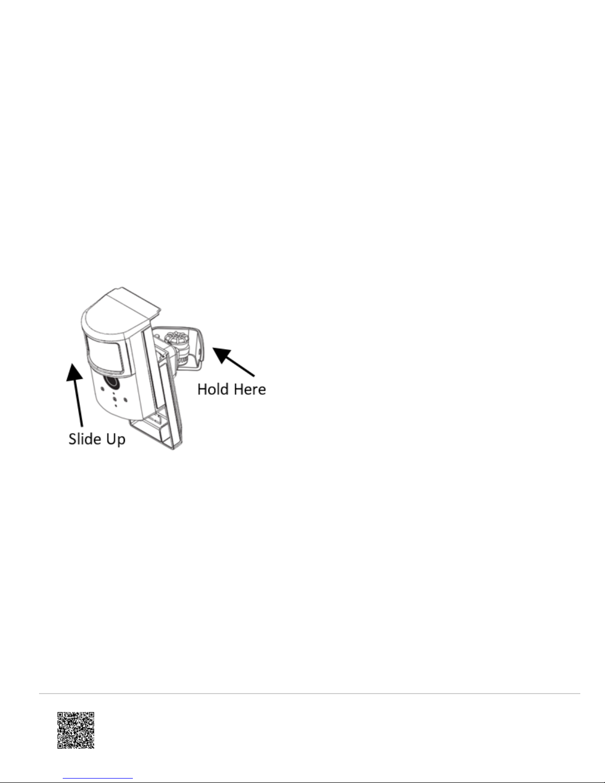
Replacing batteries: To replace the sensor batteries, slide the front of the sensor up off the sensor-back. Dispose of
used batteries per the battery manufacturer instructions and following local regulations.
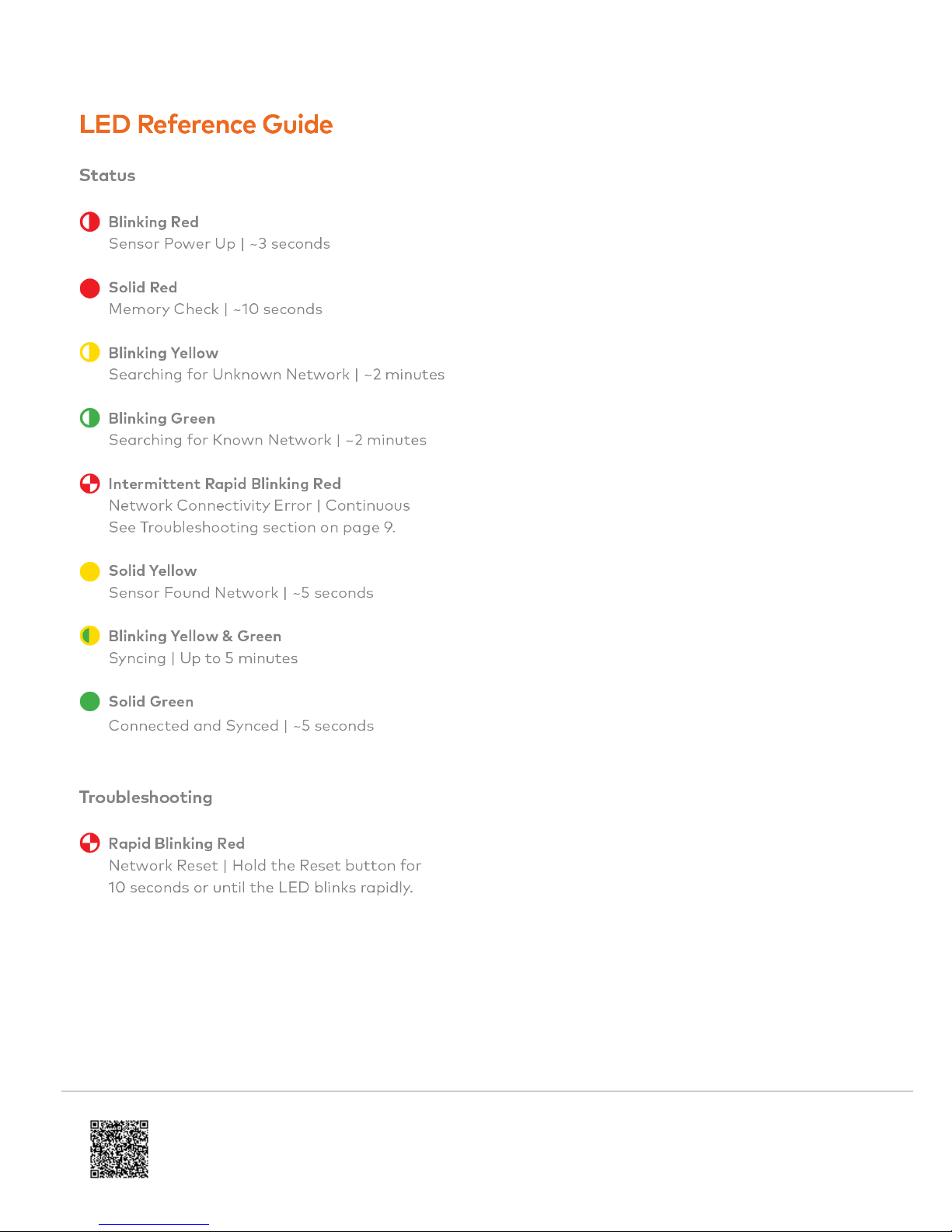
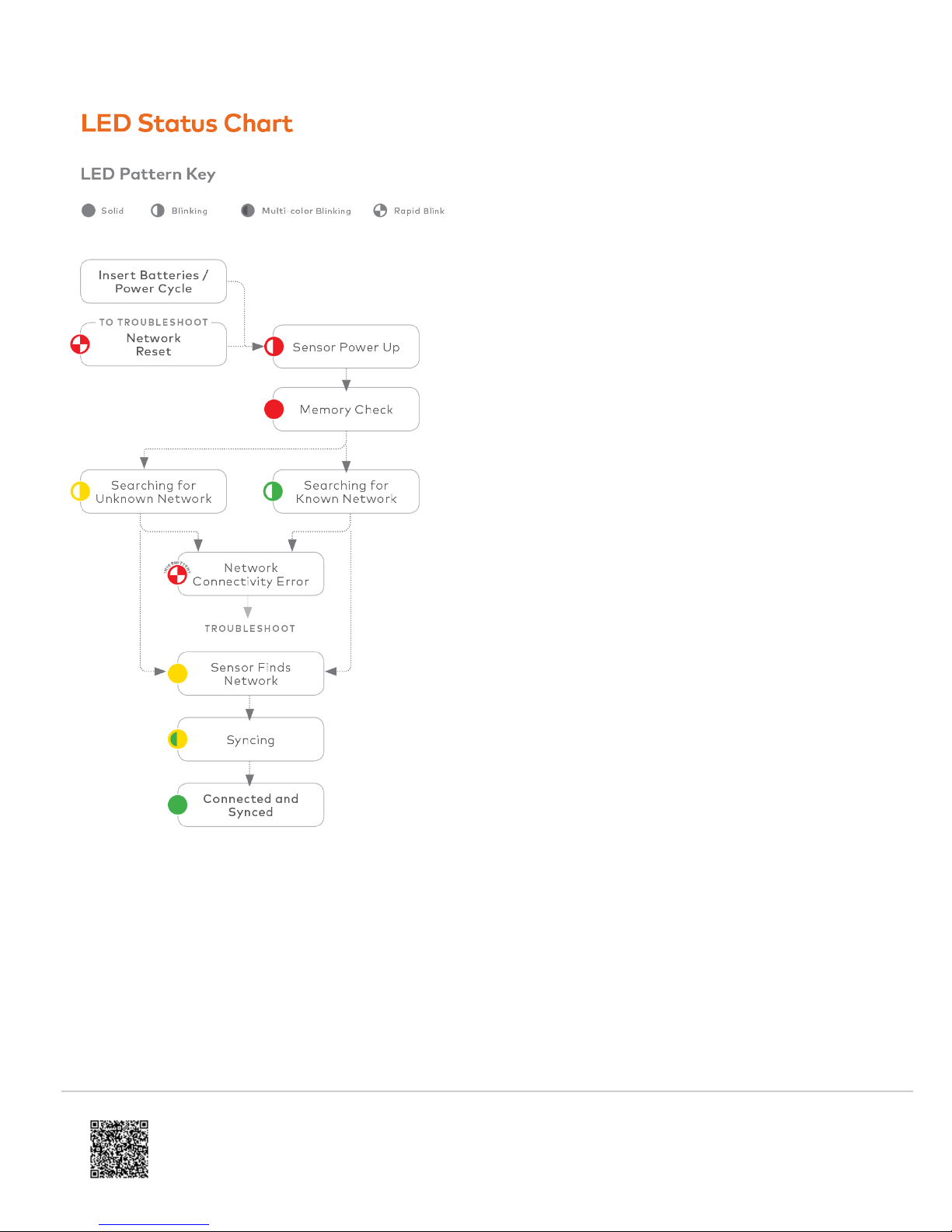
CAMERA LED REFERENCE CHART
Camera LED Chart: Refer to this chart to understand the camera LED patterns.
3
Page 4
https://answers.alarm.com/Installation_and_Troubleshooting/Image_Sensor/Interlogix_Simon_XTi_Image_Sensor/Interlogix_Simon_XTi_Image_Sensor_Installation_Guide_-_ADC-IS-300-LP
Updated: Tue, 17 Apr 2018 13:48:15 GMT
4
Page 5
RESETTING THE IMAGE SENSOR
https://answers.alarm.com/Installation_and_Troubleshooting/Image_Sensor/Interlogix_Simon_XTi_Image_Sensor/Interlogix_Simon_XTi_Image_Sensor_Installation_Guide_-_ADC-IS-300-LP
Updated: Tue, 17 Apr 2018 13:48:15 GMT
There are two ways to reset the Image Sensor:
• Power Cycle – Power Cycle can be done by one of two ways: (1) Take out and reinsert batteries or (2) press and
release the sensor reset button. Only initiate a power cycle if the LED has not been active in the last 10 seconds.
After a power cycle, the Image Sensor will enter sensor power up state followed by the memory check state.
• Network Reset - An Image Sensor must be network reset when it has been previously enrolled on a different panel.
The Image Sensor will indicate that it is enrolled on a panel by blinking green after the memory check. In order to
perform a network reset, press and hold the reset button for a full 10 seconds or until the red LED flashes rapidly.
Release as sobon as you see the rapidly flashing red LED. A successful network reset will result in the LED blinking
5
Page 6

yellow after the memory check (solid red LED).
https://answers.alarm.com/Installation_and_Troubleshooting/Image_Sensor/Interlogix_Simon_XTi_Image_Sensor/Interlogix_Simon_XTi_Image_Sensor_Installation_Guide_-_ADC-IS-300-LP
Updated: Tue, 17 Apr 2018 13:48:15 GMT
A network reset will only work if the Image Sensor is not actively communicating with a network. If the Image
Sensor is within range of the original panel, it is required that the Image Sensor first be deleted from the panel it
was previously learned into before being able to perform a network reset on the Image Sensor. See instructions on
how to properly delete the Image Sensor from the panel. After releasing the reset button, the Image Sensor will
enter sensor power-up mode (blinking red LED) followed by memory check (solid red LED) followed by either a
blinking green or blinking yellow light. See Camera LED Reference Chart for the full list of status indicators and
expected behaviors.
PIR ACTIVATION & TEST MODE
By default, the image sensor LED does not illuminate when activated by motion unless the sensor is in test mode. The
LED can be enabled by tampering the device, via the Alarm.com Dealer Website, or on the panel for each Image Sensor
on a customer’s account. The Image Sensor must have successfully completed the enrollment process with a panel.
When enabled, the red LED illuminates for 3 seconds upon motion activations (at most every 3 minutes while disarmed).
Instructions to activate on the panel (Note: It may take up to 30 seconds for test mode to take effect after requesting
“Test PIR” at the panel):
• On the XT panel, go to “Image Sensor Setup” menu and scroll to “Image Sensor Settings”. Enter “Image Sensor
Settings” and scroll to the sensor to test, press “OK.” Scroll to “Image Sensor [y] Test PIR,” and press OK to put the
device in test mode.
• On the XTi panel, enter the “Test” menu under “Image Sensor” and press “PIR”. The screen will display a
confirmation to indicate the test mode command has been sent.
Test mode cannot be activated from the Concord panel.
TAMPER & TROUBLE CONDITIONS
Tamper: A built-in accelerometer detects movement or re-positioning of the Image Sensor and will initiate a tamper
whenever a change in sensor orientation is detected. The tamper automatically clears after the sensor is returned to the
upright position and no movement has been detected for 5 minutes. A tamper can also be cleared by resetting the
sensor.
Trouble Conditions: By default, trouble conditions (malfunction, tamper & low battery) are displayed on the panel LCD.
Enable or disable trouble condition messages on the control panel LCD via the Alarm.com Dealer Website. Trouble
conditions are always reported to the Alarm.com Customer Website and customers will receive tamper/low/malfunction
notifications if they are subscribed, regardless of the panel setting.
6
Page 7

SERVICE PLANS REQUIREMENTS
https://answers.alarm.com/Installation_and_Troubleshooting/Image_Sensor/Interlogix_Simon_XTi_Image_Sensor/Interlogix_Simon_XTi_Image_Sensor_Installation_Guide_-_ADC-IS-300-LP
Updated: Tue, 17 Apr 2018 13:48:15 GMT
Image capture features require a service plan that includes one of the following Image Sensor add-ons:
Images - Alarms- Includes upload of images from alarm events only.
Images - Plus- Includes upload of images from alarm events and non-alarm events
INSTALLATION: PREPARING PANEL FOR ENROLLMENT
1. Create Alarm.com Customer Account - Select service plan (see Service Plan Requirements) and register the
Alarm.com module serial number on the Alarm.com Dealer Website.
2. Install Image Sensor Daughterboard if necessary. – First check Hardware Compatibility to verify if module
needs a daughterboard. If it does, see Daughterboard Install Guide for daughterboard installation instructions.
3. Install Alarm.com Module inside Control Panel
4. Register Module and Test - Power up the panel and initiate a comm-test to ensure the Alarm.com module is
properly installed and communicating with the Alarm.com NOC.
5. Enroll Sensor in Panel – Instructions specific by panel
INSTALLATION: ENROLLING IMAGE SENSOR TO PANEL
Simon XT
1. Put the panel into Add Mode. On the panel go to “System Programming” > Enter installer code (default 4-3-2-1) >
Select “Interactive Services” > Select “Image Sensor Setup” > Select “Image Sensor Learn Mode” > Screen should
display “Power up or set I. S. Mode”.
2. Insert the batteries into the Image Sensor. The LED on the Image Sensor will progress from blinking red to solid
red to blinking yellow. This indicates the Image Sensor is in learn mode.
3. Wait approximately 20 seconds for the Image Sensor to enroll to the panel. The screen on the panel will display
the following: “I.S. [x] Added as Sensor [y].” The LED on the Image Sensor will turn solid yellow indicating that it
has successfully found the panel.
4. After the Image Sensor LED has turned solid yellow, you must exit Add Mode on the panel. The Image Sensor
LED will alternate between green and yellow while the customer’s device list is updated with Alarm.com. The LED
will turn solid green when the Image Sensor has been successfully added to the customer’s account. Note: If you
move (tamper) the Image Sensor after the LED has turned solid green, the Image Sensor will enter test mode for 3
minutes indicated by red LED when motion is detected. You may continue with the mounting portion of the
installation when in test mode. See the Image Sensor LED Reference Chart for more details.
The sensor is now learned into the panel. Sensors are enrolled in group 17 by default. To change the sensor group, use
the Sensors menu in System Programming. Image Sensors may be enrolled in groups 15, 17, 20, or 25. (No chime
issued for group 25.) On the Simon XT a mix of sensor groups 15/17 and 20 are not supported. If Image Sensors are in
group 15 or 17, they cannot also be in group 20, and vice versa. After enrollment, be sure to keep the sensor and panel
powered so the sensor can complete an initialization process with the Alarm.com Network Operations Center. This
process will take several minutes. Images cannot be captured until initialization is complete. Check by verifying if the
rules are confirmed on the dealersite or MobileTech.
7
Page 8

Simon XTi/XTi-5
https://answers.alarm.com/Installation_and_Troubleshooting/Image_Sensor/Interlogix_Simon_XTi_Image_Sensor/Interlogix_Simon_XTi_Image_Sensor_Installation_Guide_-_ADC-IS-300-LP
Updated: Tue, 17 Apr 2018 13:48:15 GMT
1. Put the panel into add mode. On the panel, scroll until the screen shows “Programming” > Enter installer code
(default 4-3-2-1) > Select “Interactive Services” > Select “Image Sensor” > Select “Add” > The screen will display
“Reset or power-up sensor to enroll…”
2. Insert the batteries into the Image Sensor. The LED on the Image Sensor will progress from blinking red to solid
red to blinking yellow. This indicates the Image Sensor is in learn mode.
3. Wait approximately 20 seconds for the Image Sensor to enroll to the panel. The screen on the panel will display
the following: “I.S. [x] Added as Sensor [y].” The LED on the Image Sensor will turn solid yellow indicating that it
has successfully found the panel.
4. After the Image Sensor LED has turned solid yellow, you must exit Add Mode on the panel. The Image Sensor
LED will alternate between green and yellow while the customer’s device list is updated with Alarm.com. The LED
will turn solid green when the Image Sensor has been successfully added to the customer’s account. Note: If you
move (tamper) the Image Sensor after the LED has turned solid green, the Image Sensor will enter test mode for 3
minutes indicated by red LED when motion is detected. You may continue with the mounting portion of the
installation when in test mode. See the Image Sensor LED Reference Chart for more details.
The sensor is now learned into the panel. Sensors are enrolled in group 17 by default. To change the sensor group, use
the Sensors menu in Programming. Image Sensors may be enrolled in groups 15, 17, 20, or 25. (No chime issued for
group 25.) After enrollment, be sure to keep the sensor and panel powered so the sensor can complete an initialization
process with the Alarm.com Network Operations Center. This process will take several minutes. Images cannot be
captured until initialization is complete. Check by verifying if the rules are confirmed on the dealersite or MobileTech.
Concord
1. Install Image Sensor Daughterboard – See Daughterboard Install Guide for more details.
2. Connect Daughterboard Alarm Wire – See Daughterboard Install Guide for more details.
3. Register Module and Test - Power up the panel and initiate a comm-test to ensure the Alarm.com module is
properly installed and communicating with the Alarm.com NOC.
4. Press button on IS daughterboard to enter ‘Add Mode.’ The green LED “Z2” will start a 4-blink pattern indicating
that the daughterboard is in ‘Add Mode’.
5. Reset or insert the batteries into the image sensor. “Z2” LED on the daughterboard will be solid for 60 seconds to
indicate that the sensor has been added.
6. The LED on the Image Sensor will progress from blinking red to solid red to blinking yellow to solid yellow.
Note: The Image Sensor WILL NOT show in the panel’s sensors menu as occupying a panel zone, but the zone
must be reserved for the Image Sensor. It is enrolled starting with zone 92 and counts down. The Alarm.com
Dealer Site equipment list will show the Image Senor in its enrolled zone. By default, the sensors are enrolled in
partition 1 and group 17. During step 6, the Image Sensors will be re-assigned to follow the partition and group of
the hardwire.
7. To begin enrolling Image Sensor Alarm Hardwire in panel - Enter sensor enrollment menu in System
Programming.
8. Select the partition number, zone number, and sensor group for the hardwire.
9. Trip daughterboard hardwire by pressing button on top of daughterboard. The red LED “Z1” on daughterboard will
turn off when pressed.
10. Exit system programming. The Image Sensors will now be assigned to the group and partition of the hardwire.
8
Page 9

11. The Image Sensor LED will alternate between green and yellow while the customer’s device list is updated with
https://answers.alarm.com/Installation_and_Troubleshooting/Image_Sensor/Interlogix_Simon_XTi_Image_Sensor/Interlogix_Simon_XTi_Image_Sensor_Installation_Guide_-_ADC-IS-300-LP
Updated: Tue, 17 Apr 2018 13:48:15 GMT
Alarm.com. The LED will turn solid green when the Image Sensor has been successfully added to the customer’s
account. Note: If you move (tamper) the Image Sensor after the LED has turned solid green, the Image Sensor will
enter test mode for 3 minutes indicated by red LED when motion is detected. You may continue with the mounting
portion of the installation when in test mode. See the Image Sensor LED Reference Chart for more details.
Image Sensors may be enrolled in groups 15, 17, 20, or 25. The Image Sensors must follow the partition and group of
the alarm hardwire and cannot be individually configured. After enrollment, be sure to keep the sensor and panel
powered so the sensor can complete an initialization process with the Alarm.com Network Operations Center. This
process will take several minutes. Images cannot be captured until initialization is complete. Check by verifying if the
rules are confirmed on the dealersite or MobileTech.
INSTALLATION: MOUNTING IMAGE SENSOR
1. Determine the desired mounting angle – 3 options
9
Page 10

2. Screw bracket to back plate.
https://answers.alarm.com/Installation_and_Troubleshooting/Image_Sensor/Interlogix_Simon_XTi_Image_Sensor/Interlogix_Simon_XTi_Image_Sensor_Installation_Guide_-_ADC-IS-300-LP
Updated: Tue, 17 Apr 2018 13:48:15 GMT
10
Page 11

3. Determine location to mount sensor.
https://answers.alarm.com/Installation_and_Troubleshooting/Image_Sensor/Interlogix_Simon_XTi_Image_Sensor/Interlogix_Simon_XTi_Image_Sensor_Installation_Guide_-_ADC-IS-300-LP
Updated: Tue, 17 Apr 2018 13:48:15 GMT
4. Choose applicable mounting bracket. The sensor hardware packet contains two mounting brackets for different
mounting scenarios. Use the provided large screws and anchors to attach the bracket to the wall. (Leave at least
3 inches of clearance above the sensor to allow for battery replacement without uninstalling the mounting
11
Page 12

bracket.)
https://answers.alarm.com/Installation_and_Troubleshooting/Image_Sensor/Interlogix_Simon_XTi_Image_Sensor/Interlogix_Simon_XTi_Image_Sensor_Installation_Guide_-_ADC-IS-300-LP
Updated: Tue, 17 Apr 2018 13:48:15 GMT
5. Place sensor with arm on mounting bracket. Adjust the horizontal positioning of the sensor to point towards the
desired coverage area.
6. Secure the mounting arm location by sliding lock pin into the hole. Use the washer and remaining small screw to
secure the lock pin by screwing upwards through the bottom of the hole in the mounting bracket.
7. Set PIR Sensitivity Settings – 3 options that can be set through the panel or on the dealersite:
8. Verify and Test Image Sensor Setup
12
Page 13

a. Verify that rules are confirmed via the dealersite or on MobileTech, Resend rules if they are not confirmed.
https://answers.alarm.com/Installation_and_Troubleshooting/Image_Sensor/Interlogix_Simon_XTi_Image_Sensor/Interlogix_Simon_XTi_Image_Sensor_Installation_Guide_-_ADC-IS-300-LP
Updated: Tue, 17 Apr 2018 13:48:15 GMT
b. Verify RF Coverage by checking that the signal strength is above 40%. The signal strength must be greater
than 30% for sensor to function properly.
c. Conduct walk test - To conserve the customer’s monthly image upload quota, automatic alarm uploads are
disabled for the first four hours after any new sensor (Image Sensor or other) is installed into the system.
Installers can also test by requesting image uploads and motion image uploads via MobileTech. Installers are
required to be onsite to test by running a comm test at the panel.
d. Test night captures.
DELETING IMAGE SENSOR FROM PANEL
Instructions on how to properly delete and Image Sensor from a system. It is important to do the steps in order.
Delete the Image Sensor from the account using the panel’s Interactive Services, Dealersite or Mobiletech.
Perform a network reset of the Image Sensor. Seeing instructions on how to network reset an Image Sensor. You will
only be able to do this after you’ve completed step 1 or if the Image Sensor is out of range of its current network.
PIR Lens and Camera Coverage Diagrams
Figure 3.Side View: PIR Lens Coverage
13
Page 14

Figure 4.Top View: PIR Lens Coverage
https://answers.alarm.com/Installation_and_Troubleshooting/Image_Sensor/Interlogix_Simon_XTi_Image_Sensor/Interlogix_Simon_XTi_Image_Sensor_Installation_Guide_-_ADC-IS-300-LP
Updated: Tue, 17 Apr 2018 13:48:15 GMT
As indicated in Figure 4, the camera coverage area is narrower than the PIR coverage area. When installing, mount
sensor where subjects are likely to be centered in or across PIR and camera field of view.
TROUBLESHOOTING
General Troubleshooting Steps
• Verify Module Signal Strength
• Verify Image Sensor RF Signal Strength: The signal strength must be above 30% for the sensor to function
properly.
• Verify Images Service Plan: Image capture functionality depends on the customer’s service plan. Be sure the proper
Image Sensor service plan is selected.
Enrollment
• Verify Sensor is Receiving Power: After inserting batteries, the sensor LED should illuminate or flash within 10
seconds.
• Verify Sensor is Not Communicating with Another Network: If the sensor has been previously enrolled in a different
system or daughterboard, delete the sensor from the system and hold the sensor reset button for 10 seconds to
clear the sensor from old network before attempting to enroll the sensor in a new network. The sensor cannot be
cleared if it is currently communicating with its network. In this case the sensor must be deleted from the system
first through the control panel or remote command.
14
Page 15

Sensor Non-Responsive
https://answers.alarm.com/Installation_and_Troubleshooting/Image_Sensor/Interlogix_Simon_XTi_Image_Sensor/Interlogix_Simon_XTi_Image_Sensor_Installation_Guide_-_ADC-IS-300-LP
Updated: Tue, 17 Apr 2018 13:48:15 GMT
• Verify Range: Under the “Image Sensor Setup” menu, scroll to “Image Sensor Settings,” select the sensor and
verify under “Signal” that the sensor is registering a strong signal. If signal strength is low, move non-responsive
sensor closer to control panel, verify signal strength and see if communication resumes. Be sure that Image Sensor
daughterboard antenna is correctly routed as indicated in step 5 of the installation procedure.
• Replace Batteries: Check battery level at the panel (under “Image Sensor Settings”) and install fresh sensor
batteries.
Images Not Captured
• Verify Sensor Rules: Make sure the sensor initialization process has been completed. On the Dealer Website,
verify rules have been confirmed using the “Rules Confirmed” column. If not, resend Image Sensor rules.
• Enable Auto Uploads: During the first four hours after any sensor is enrolled onto the system, alarm images will not
automatically be uploaded to Alarm.com. Automatic uploads are automatically enabled after four hours. Enable
uploads sooner from the Dealer Website.
False Motion Activations
• Check Environmental Elements: Heating or cooling elements may adversely affect sensor performance. Test
sensor with and without these elements to determine interference. Check if there are any reflective surfaces facing
the device (e.g. mirror).
• Check Sensor Positioning: The sensor may not be properly positioned to capture the desired motion. Check
horizontal positioning of sensor and re-mount as necessary.
• Check PIR Sensitivity Setting: Verify that the proper sensor motion profile has been selected through the setup
menu or select a less sensitive profile.
15
 Loading...