

Page 1

TOPAZ ACURT2 & ACURT4
Hardware Installation Guide
Page 2

Copyright
Copyright © 2006, GE Security Inc. All rights reserved.
This document may not be copied or otherwise reproduced, in whole or in part, except as
specifically permitted under US and international copyright law, without the prior written
consent from GE.
Document number 460933001B (May 2006).
Disclaimer THE INFORMATION IN THIS DOCUMENT IS SUBJECT TO CHANGE WITHOUT NOTICE. GE ASSUMES
NO RESPONSIBILITY FOR INACCURACIES OR OMISSIONS AND SPECIFICALLY DISCLAIMS ANY
LIABILITIES, LOSSES, OR RISKS, PERSONAL OR OTHERWISE, INCURRED AS A CONSEQUENCE,
DIRECTLY OR INDIRECTLY, OF THE USE OR APPLICATION OF ANY OF THE CONTENTS OF THIS
DOCUMENT. FOR THE LATEST DOCUMENTATION, CONTACT YOUR LOCAL SUPPLIER OR VISIT US
ONLINE AT WWW.GESECURITY.COM.
This publication may contain examples of screen captures and reports used in daily operations.
Examples may include fictitious names of individuals and companies. Any similarity to names
and addresses of actual businesses or persons is entirely coincidental.
Trademarks and patents GE and the GE monogram are registered trademarks of General Electric.
TOPAZ ACURT2 and ACURT4 are trademarks of GE Security.
Other trade names used in this document may be trademarks or registered trademarks of the
manufacturers or vendors of the respective products.
Intended use Use this product only for the purpose it was designed for; refer to the data sheet and user
documentation. For the latest product information, contact your local supplier or visit us online
at www.gesecurity.com.
FCC compliance This equipment has been tested and found to comply with the limits for a Class A digital device,
pursuant to part 15 of the FCC Rules. These limits are designed to provide reasonable protection
against harmful interference when the equipment is operated in a commercial environment.
This equipment generates, uses, and can radiate radio frequency energy and, if not installed
and used in accordance with the instruction manual, may cause harmful interference to radio
communications.
You are cautioned that any changes or modifications not expressly approved by the party
responsible for compliance could void the user's authority to operate the equipment.
Modems The Part 68 rules require the following or the equivalent information be provided to the end user
of equipment containing a pre-approved modem module.
Type of Service The TOPAZ System operates on a GE Security ACURT field panels and is designed to use a
standard device telephone lines. It connects to the telephone line by means of a standard jack
called the USOC RJ-11C (or USOC FJ45S.) Connection to the telephone company provided coin
service (central office implemented systems) is prohibited. Connection to party line services is
subject to state tariffs.
Telephone Company
Procedures
The goal of the telephone company is to provide you with the best service it can. In order to do
this, it may occasionally be necessary for them to make changes in their equipment,
operations, or procedures. These changes might affect your service or the operation of your
equipment, the telephone company will give notice, in writing, to allow you to make any
changes necessary to maintain uninterrupted service.
In certain circumstances, it may be necessary for the telephone company to request
information from you concerning what equipment you have connected to your telephone line.
Upon request from the telephone company, provide the FCC registration number and the ringer
equivalence number (REN); both of these items are listed on the equipment label. The sum of all
the RENs on your telephone line should be less than five in order to assure proper service from
the telephone company. In some cases, five may not be usable on a given line.
Page 3

If problems Arise If any of your telephone equipment is not operating, you should immediately remove it from
Contact Us
your telephone line, as it may cause harm to the telephone network. If the telephone company
notes a problem, they may temporarily discontinue service. When practical, they will notify you
in advance of this disconnection. If advanced notice is not feasible, you will be notified as soon
as possible. When you are notified, you will be given the opportunity to correct the problem and
informed of your right to file a complaint with the FCC. Contact your telephone company if you
have any questions about your phone line. In the event repairs are ever needed on the GE
Security ACURT field panel they should be performed by GE Security technicians or an
authorized representative.
Returning Procedure
Contact the distributor where the product was purchased for return policy and
procedures.
GE Security Address
Correspondence should be sent to the following address:
GE Security
12345 SW Leveton Drive
Tualatin, OR 97062
USA
800-547-2556
Technical Support: (888) GESecurity (888) 437-3287
Electronic Email Addresses
Technical Support - infra-techsupport-Ilx-Topaz@ge.com
Web Site
www.GESecurity.com
Page 4

TOPAZ ACURT2 & ACURT4
I.iv
Hardware Installation Guide
Page 5

UL Standards
The following has been determined by Underwriters Laboratories to be compatible with the ACURT2/
ACURT4.
• GE Security Remote Input Modules (RIM)
• GE Security Remote Relay Modules (RRM)
• GE Security Keypads
• HID ProxPro Model 5355 with and without keypad
• HID ProxPoint Model 6005
• HID MiniProx Model 5365
• HID MiniProx Model 5375
• GE Security Magstripe Extender
Note: Any reader or keypads other than the ones listed are not to be used on a UL listed system.
UL / CUL Specifications
I.v
TOPAZ Software Revision 1.44
In order to comply with UL 1076 and /or UL 294 t he foll owing it ems must be adhere d to, if no t, the i nstal lati on
site will be in violation of the UL requirements.
The ACU panel must be powered by an Altronix AL400UL3 Power Supply. This must be located in the same
room as the panel and no more than 25 feet from the unit. See Figure 1..
The DC input rating on the ACURT2/ACUR T4 is +24VDC +-4V @ 750ma. max. with all outputs at max imum
load.
Combined Auxiliary Power rating for all 4 readers on the ACURT4 must not exceed a maximum of 900Ma.
Only UL listed equipment may be co nnected to the GE Securit y system. This includes e xternal po wer supplie s,
motion detector, door contacts, enclosures, etc.
All RRM and RIM modules must be installed in the room with panel and no more than 25 feet from the unit.
The End-Of-Line resistor must be located within the alarm zone sensor enclosure.
Shielded cables must be used for all communication and read head runs.
The use of the dial up modem or any other network connection on the ACURT2/ACUR T4 mu st not be used for
UL Certified Installations.
All Receiving equipment must meet the following Conditions:
The Central Supervising Station Equipment shall have the following minimum system configuration: 400
Mhz Pentium II with 512 KB Cache, 128 megabytes of RAM, 6 Gigabytes hard drive and 2 megabytes
video memory , W indows 200 0 or XP Profess ional. (Thi s is the mini mum system requi rements. Howeve r , a
1.2 Ghz Pentium IV with 512 megabytes of Ram is reco mme nded . ) Data processing equipment and offi ce
appliance and business equipment used as central supervisory station equipment shall comply with;
The Standard for Office Appliance and Business Equipment, UL 114;
The Standard for Information-Processing and Business Equipment, UL 478; or
The Standard for Information Technology Equipment, UL 1950.
Page 6

TOPAZ ACURT2 & ACURT4
I.vi
Hardware Installation Guide
Line transient pro tect ion compl ying wi th t he S t andard for Transient Volta ge Sur g e Supp resso rs, UL 1449, with
a maximum marked rating of 330V shall be used.
Signal line transient pro te ct ion compl yi ng wit h the Standard for Protectors for Data Communications and Fire
Alarm Circuits, UL 497B, with a maximum marked rating of 50 V shall be used.
Communication circuits and network components connected to the telecommunications network shall be
protected by second ary protec tors for communicati on circuit s. These pro tectors shall compl y with the S tandar d
for Secondary Protectors For Communications Circuits, UL 497A. These protectors shall be used only in the
protected side of the telecommunications network.
Equipment shall b e instal led in a tempera ture cont rolled environment . A te mperature control led envir onment is
defined as one that can be maintained between 13 – 35 C (55 – 95 F) by th e HVAC system. Twenty-four hours
of standby power shall be provided for the HVAC system. The standby power system for the HVAC system
may be supplied by an engine driven generator alone. A standby battery is not required to be used.
All receiving equipment shall be completely duplicated with provision for switchover to the backup system
within 30 seconds. The backup system shall be fully operational within 6 minutes of the loss of the primary
system. This allows 30 seconds for the backup system to be fully energized and connected to necessary
communication lines and other devices, followed by 5-1/2 minu te s f or t he system to boot up, conduct memory
tests, file s ystem check , securit y verific ations an d prepare for ful l syste m operatio n. The b ackup comput er shall
have the capabilities of the primary, such as memory, speed and the like.
Failure of the main computer system, hard disk, and alarm monitor shall result in switchover to the backup
system and shall be indicated by an audible or obvious visual indication.
A fault tolerant system may be used in lieu of complete duplication of the system if every component in the
fault tolerant system, including the software and the power supply, is duplicated.
In addition to the main po wer supply and second ary po wer supply that ar e requir ed to be p rovide d at the central
supervisory station, the system shall be provided with an uninterruptible power supply (UPS) with sufficient
capacity to operate th e computer equipment for a minimum of 15 minutes. If mo re t han 15 minutes is required
for the secondary power supply to supply the UPS input power, the UPS shall be capable of providing input
power for at least that amount of time.
The UPS shall comply with the Standard for Uninterruptible Power Supply Equipment, UL 1778, or the
Standard for Fire Protective Signaling Devices, UL 1481.
In order to perform maintenance and repair service, a means for disconnecting the input to the UPS while
maintaining continuity of power to the au tomation system shall be provided
Figure 1. Wiring Diagram for Altronix AL400UL3
TB6-5
TB6-6
1K 1%
TB11-1
TB11-2
1K
1%
See Low Battery Alarm
setup procedure
AC
Input
Bat
Fail
AC
Fail
AL400UL3
24VDC
Ouput
-
+
TB10 - 7
TB10 - 6
For Canadian Certification installations, the model Brownsville or Easton 2 Computer must be used with this
system and the installation must follow the Canadian Electrical Code, Part 1.
Page 7

Low Battery Alarm Setup
1. From Topaz main screen go to Hardware then Alarm Point tab.
2. Click Clear then enter Alarm Name: Low Battery Panel #.
3. Select Field Panel (this procedure must be done for each ACURT panel.
4. Select Security Area,
5. Select Alarm Category
6. Select Alarm Instruction
7. Select Active.
8. Select Input Number 22
9. Select Priority 5.
10. Uncheck User ACK Required and Alarm Can Be Masked.
11. Set Alarm Reporting Delay to “0” and enter the Description.
12. Click Save.
I.vii
NFPA Standard
National Fire Protection Association
1 Batterymarch Park
Quincy, MA 02269
617-770-3000
www.nfpa.org
NFPA 70 Article 250, NEC
Page 8
I.viii
TOPAZ ACURT2 & ACURT4
Hardware Installation Guide
FOR YOUR SAFETY
The following WARNINGS: and CAUTIONS: appear here for your saf et y. They are general in nature and do
not pertain to specific procedural steps. There are, however, additional safety precautions that do pertain to
specific procedural steps. These precautions appear at the point in the installation and/or maintenance
procedures where a hazard is most likely to be encountered.
BE SURE to read and follow all personal safety WARNINGS and equipment CAUTIONS appearing in this
document PRIOR to beginning ACU installation.
WARNING: The ACURT components described in this manual contain electrical shock hazard potential. Only
qualified personnel should perform installation and maintenance. Use the appropriate procedures to
remove power before proceeding with servicing.
WARNING: Do not use the ACURT Controller, Remote Input Module (RIM) or Remote Relay Module (RRM) to switch
any voltage above 30 volts. Failure to heed this WARNING: can cause death, personal injury or damage
to unit(s).
WARNING: Make certain that the AC power source circuit breaker is OFF BEFORE proceeding. Failure to heed this
WARNING can cause damage to unit(s).
CAUTION: The ACURT controllers must have separate conduit run to each enclosure. Only cables/wires that begin or
terminate in the enclosure should run into the enclosure. DO NOT use the enclosure(s) as "pull-boxes" for
any foreign wiring. The enclosures should be arranged for separate conduit runs.
NOTICE: Fire Safety Notice
WARNING: NEVER connect any card reader devices or locks onto doors, gates or barriers that may be fire exits
without first consulting and getting approval of applicable local officials. Use of push buttons to exit
may be illegal. Single action exit may be required. Obtain proper permits and approvals in writing
before installation.
Page 9

Table of Contents
UL Standards . . . . . . . . . . . . . . . . . . . . . . . . . . . . . . . . . . . . . . . . . . . . . . . . . . . . . . . . . . . . . . . . . . . . . . . . . . . . . . . . . . . v
UL / CUL Specifications. . . . . . . . . . . . . . . . . . . . . . . . . . . . . . . . . . . . . . . . . . . . . . . . . . . . . . . . . . . . . . . . . . . . . . . . . . . . . . .v
NFPA Standard . . . . . . . . . . . . . . . . . . . . . . . . . . . . . . . . . . . . . . . . . . . . . . . . . . . . . . . . . . . . . . . . . . . . . . . . . . . . . . . . . . . . . vii
FOR YOUR SAFETY . . . . . . . . . . . . . . . . . . . . . . . . . . . . . . . . . . . . . . . . . . . . . . . . . . . . . . . . . . . . . . . . . . . . . . . . . . . . . viii
Table of Contents. . . . . . . . . . . . . . . . . . . . . . . . . . . . . . . . . . . . . . . . . . . . . . . . . . . . . . . . . . . . . . . . . . . .ix
List of Tables. . . . . . . . . . . . . . . . . . . . . . . . . . . . . . . . . . . . . . . . . . . . . . . . . . . . . . . . . . . . . . . . . . . . . . . . . . . . . . . . . . xiv
List of Figures . . . . . . . . . . . . . . . . . . . . . . . . . . . . . . . . . . . . . . . . . . . . . . . . . . . . . . . . . . . . . . . . . . . . . . . . . . . . . . . . . xvi
Chapter 1. The TOPAZ ACURT. . . . . . . . . . . . . . . . . . . . . . . . . . . . . . . . . . . . . . . . . . . . . . . . . . . . . . . 1
Overview . . . . . . . . . . . . . . . . . . . . . . . . . . . . . . . . . . . . . . . . . . . . . . . . . . . . . . . . . . . . . . . . . . . . . . . . . . . . . . . . . . . . . . . 2
General Specifications . . . . . . . . . . . . . . . . . . . . . . . . . . . . . . . . . . . . . . . . . . . . . . . . . . . . . . . . . . . . . . . . . . . . . . . . . . . 3
ACURT2 System Diagram. . . . . . . . . . . . . . . . . . . . . . . . . . . . . . . . . . . . . . . . . . . . . . . . . . . . . . . . . . . . . . . . . . . . . . . . . 4
ACURT4 System Diagram. . . . . . . . . . . . . . . . . . . . . . . . . . . . . . . . . . . . . . . . . . . . . . . . . . . . . . . . . . . . . . . . . . . . . . . . . 5
I.ix
Chapter 2. Installing the ACURT Panel. . . . . . . . . . . . . . . . . . . . . . . . . . . . . . . . . . . . . . . . . . . . . . . 7
Running the Wire and Cable . . . . . . . . . . . . . . . . . . . . . . . . . . . . . . . . . . . . . . . . . . . . . . . . . . . . . . . . . . . . . . . . . . . . . . 8
RS-485 Communications . . . . . . . . . . . . . . . . . . . . . . . . . . . . . . . . . . . . . . . . . . . . . . . . . . . . . . . . . . . . . . . . . . . . . . . . . 9
Pulling Wire and Cable . . . . . . . . . . . . . . . . . . . . . . . . . . . . . . . . . . . . . . . . . . . . . . . . . . . . . . . . . . . . . . . . . . . . . . . . . . 10
Baud Rates and Distances. . . . . . . . . . . . . . . . . . . . . . . . . . . . . . . . . . . . . . . . . . . . . . . . . . . . . . . . . . . . . . . . . . . . . . . . . . 10
Grounding Connections . . . . . . . . . . . . . . . . . . . . . . . . . . . . . . . . . . . . . . . . . . . . . . . . . . . . . . . . . . . . . . . . . . . . . . . . . . . . 10
Alarm Zone Sensor Wiring. . . . . . . . . . . . . . . . . . . . . . . . . . . . . . . . . . . . . . . . . . . . . . . . . . . . . . . . . . . . . . . . . . . . . . . . . . 11
Network Communications. . . . . . . . . . . . . . . . . . . . . . . . . . . . . . . . . . . . . . . . . . . . . . . . . . . . . . . . . . . . . . . . . . . . . . . 13
Setting IP Address. . . . . . . . . . . . . . . . . . . . . . . . . . . . . . . . . . . . . . . . . . . . . . . . . . . . . . . . . . . . . . . . . . . . . . . . . . . . . . . . . . 14
Installing UPS Batteries . . . . . . . . . . . . . . . . . . . . . . . . . . . . . . . . . . . . . . . . . . . . . . . . . . . . . . . . . . . . . . . . . . . . . . . . . 22
Installing and Connecting . . . . . . . . . . . . . . . . . . . . . . . . . . . . . . . . . . . . . . . . . . . . . . . . . . . . . . . . . . . . . . . . . . . . . . . . . . 22
Dial-up Modem. . . . . . . . . . . . . . . . . . . . . . . . . . . . . . . . . . . . . . . . . . . . . . . . . . . . . . . . . . . . . . . . . . . . . . . . . . . . . . . . . 23
Installing Dial-up Modem. . . . . . . . . . . . . . . . . . . . . . . . . . . . . . . . . . . . . . . . . . . . . . . . . . . . . . . . . . . . . . . . . . . . . . . . . . . 23
Connecting the Dial-up Modem. . . . . . . . . . . . . . . . . . . . . . . . . . . . . . . . . . . . . . . . . . . . . . . . . . . . . . . . . . . . . . . . . . . . . 24
Component Layout . . . . . . . . . . . . . . . . . . . . . . . . . . . . . . . . . . . . . . . . . . . . . . . . . . . . . . . . . . . . . . . . . . . . . . . . . . . . . . . . 24
LEDs on Modem Board . . . . . . . . . . . . . . . . . . . . . . . . . . . . . . . . . . . . . . . . . . . . . . . . . . . . . . . . . . . . . . . . . . . . . . . . . . . . . 24
Connecting (MDD) Multi-Drop Dial-Up Panels . . . . . . . . . . . . . . . . . . . . . . . . . . . . . . . . . . . . . . . . . . . . . . . . . . . . . . . . 25
Modem Board Replacement . . . . . . . . . . . . . . . . . . . . . . . . . . . . . . . . . . . . . . . . . . . . . . . . . . . . . . . . . . . . . . . . . . . . . . . . 25
Installing Server External Modem . . . . . . . . . . . . . . . . . . . . . . . . . . . . . . . . . . . . . . . . . . . . . . . . . . . . . . . . . . . . . . . . 26
Troubleshooting . . . . . . . . . . . . . . . . . . . . . . . . . . . . . . . . . . . . . . . . . . . . . . . . . . . . . . . . . . . . . . . . . . . . . . . . . . . . . . . . . . . 26
ACURT2 and ACURT4 Enclosure Layout . . . . . . . . . . . . . . . . . . . . . . . . . . . . . . . . . . . . . . . . . . . . . . . . . . . . . . . . . . . . . 27
ACURT2 and ACURT4 Component Layout . . . . . . . . . . . . . . . . . . . . . . . . . . . . . . . . . . . . . . . . . . . . . . . . . . . . . . . . . . . 28
Page 10

TOPAZ ACURT2 & ACURT4
I.x
Hardware Installation Guide
Terminal Connector Pin Numbers . . . . . . . . . . . . . . . . . . . . . . . . . . . . . . . . . . . . . . . . . . . . . . . . . . . . . . . . . . . . . . . . 29
Connections for Terminal Block 1 . . . . . . . . . . . . . . . . . . . . . . . . . . . . . . . . . . . . . . . . . . . . . . . . . . . . . . . . . . . . . . . . . . . 29
Connections for Terminal Block 2, 3, and 4 (ACURT2 and ACURT4). . . . . . . . . . . . . . . . . . . . . . . . . . . . . . . . . . . . . 30
Connections for Terminal Block 5, 6, and 7 (ACURT2 and ACURT4). . . . . . . . . . . . . . . . . . . . . . . . . . . . . . . . . . . . . 31
Connections for Terminal Block 8 (ACURT2 and ACURT4) . . . . . . . . . . . . . . . . . . . . . . . . . . . . . . . . . . . . . . . . . . . . . 32
Connections for Terminal Block 9 (ACURT2 and ACURT4) . . . . . . . . . . . . . . . . . . . . . . . . . . . . . . . . . . . . . . . . . . . . . 32
Connections for Terminal Block 10 (ACURT2 and ACURT4) . . . . . . . . . . . . . . . . . . . . . . . . . . . . . . . . . . . . . . . . . . . . 33
Connections for Terminal Block 11 (ACURT2 and ACURT4) . . . . . . . . . . . . . . . . . . . . . . . . . . . . . . . . . . . . . . . . . . . . 33
Connections for Terminal Block 12, 13, and 14 (ACURT4 Only). . . . . . . . . . . . . . . . . . . . . . . . . . . . . . . . . . . . . . . . . 34
Connections for Terminal Block 15, 16, and 17 (ACURT4 Only). . . . . . . . . . . . . . . . . . . . . . . . . . . . . . . . . . . . . . . . . 35
Connections for Terminal Block 18 (ACURT4 Only) . . . . . . . . . . . . . . . . . . . . . . . . . . . . . . . . . . . . . . . . . . . . . . . . . . . . 36
Relay Numbering for ACURT2 and ACURT4 . . . . . . . . . . . . . . . . . . . . . . . . . . . . . . . . . . . . . . . . . . . . . . . . . . . . . . . . . . 36
Alarm Numbering for ACURT2 and ACURT4. . . . . . . . . . . . . . . . . . . . . . . . . . . . . . . . . . . . . . . . . . . . . . . . . . . . . . . . . . 37
Wiring the Host Communications . . . . . . . . . . . . . . . . . . . . . . . . . . . . . . . . . . . . . . . . . . . . . . . . . . . . . . . . . . . . . . . . 40
Bandwidth requirements . . . . . . . . . . . . . . . . . . . . . . . . . . . . . . . . . . . . . . . . . . . . . . . . . . . . . . . . . . . . . . . . . . . . . . . . . . . 40
Connecting RS-232C Interface to ACURT2 and ACURT4 Controllers . . . . . . . . . . . . . . . . . . . . . . . . . . . . . . . . . . . 40
Connecting RS-485 Converter to the ACURT2 or ACURT4 . . . . . . . . . . . . . . . . . . . . . . . . . . . . . . . . . . . . . . . . . . . . . 41
Installing the NCIC-5 RS-485 Converter. . . . . . . . . . . . . . . . . . . . . . . . . . . . . . . . . . . . . . . . . . . . . . . . . . . . . . . . . . . . . . 42
Wiring a NCIC-5 RS-485 Converter to the Server . . . . . . . . . . . . . . . . . . . . . . . . . . . . . . . . . . . . . . . . . . . . . . . . . . . . . 43
Multi-dropping RS-485 from a LAN Connected ACURT . . . . . . . . . . . . . . . . . . . . . . . . . . . . . . . . . . . . . . . . . . . . . . . . 44
DIP Switch Settings for ACURT2 and ACURT4. . . . . . . . . . . . . . . . . . . . . . . . . . . . . . . . . . . . . . . . . . . . . . . . . . . . . . . . . 44
DIP switch SW1 Communication Port Termination . . . . . . . . . . . . . . . . . . . . . . . . . . . . . . . . . . . . . . . . . . . . . . . . . . . 44
DIP Switch SW2 Settings Baud Rate, Dial-up, Parity, and Com Type . . . . . . . . . . . . . . . . . . . . . . . . . . . . . . . . . . . 45
DIP Switch SW3 Settings. . . . . . . . . . . . . . . . . . . . . . . . . . . . . . . . . . . . . . . . . . . . . . . . . . . . . . . . . . . . . . . . . . . . . . . . . . . . 46
Dip Switch SW4 (rotary switch) Settings ACURT Panel Addressing . . . . . . . . . . . . . . . . . . . . . . . . . . . . . . . . . . . . . 46
DIP Switch SW5 and SW6 Settings Alarm Zone Termination for Readers. . . . . . . . . . . . . . . . . . . . . . . . . . . . . . . 47
DIP Switch SW7 Power Switch . . . . . . . . . . . . . . . . . . . . . . . . . . . . . . . . . . . . . . . . . . . . . . . . . . . . . . . . . . . . . . . . . . . . . . 47
Status LEDs on the ACURT2 and ACURT4 . . . . . . . . . . . . . . . . . . . . . . . . . . . . . . . . . . . . . . . . . . . . . . . . . . . . . . . . . . . . 48
Defaulting the Memory on the ACURT2 and ACURT4 . . . . . . . . . . . . . . . . . . . . . . . . . . . . . . . . . . . . . . . . . . . . . . . . . 49
Chapter 3. Reader Installation . . . . . . . . . . . . . . . . . . . . . . . . . . . . . . . . . . . . . . . . . . . . . . . . . . . . 51
Overview of Reader Installation . . . . . . . . . . . . . . . . . . . . . . . . . . . . . . . . . . . . . . . . . . . . . . . . . . . . . . . . . . . . . . . . . 52
Reader Installation Direct Connection . . . . . . . . . . . . . . . . . . . . . . . . . . . . . . . . . . . . . . . . . . . . . . . . . . . . . . . . . . . . 53
Wiring HID ProxPoint Plus 6005 . . . . . . . . . . . . . . . . . . . . . . . . . . . . . . . . . . . . . . . . . . . . . . . . . . . . . . . . . . . . . . . . . . . . . 53
HID ProxPoint Plus 6005 Point to Point Wiring. . . . . . . . . . . . . . . . . . . . . . . . . . . . . . . . . . . . . . . . . . . . . . . . . . . . . . . . 54
Wiring HID MiniProx Model 5365 Reader. . . . . . . . . . . . . . . . . . . . . . . . . . . . . . . . . . . . . . . . . . . . . . . . . . . . . . . . . . . . . 55
HID MiniProx Model 5365 Point to Point Wiring. . . . . . . . . . . . . . . . . . . . . . . . . . . . . . . . . . . . . . . . . . . . . . . . . . . . . . . 56
Wiring Optional HID ProxPro Model 5355 Reader. . . . . . . . . . . . . . . . . . . . . . . . . . . . . . . . . . . . . . . . . . . . . . . . . . . . . 57
Wiring Optional HID MaxiProx Model 5375 Long Range Reader . . . . . . . . . . . . . . . . . . . . . . . . . . . . . . . . . . . . . . . 59
Wiring Optional K11L Keypad . . . . . . . . . . . . . . . . . . . . . . . . . . . . . . . . . . . . . . . . . . . . . . . . . . . . . . . . . . . . . . . . . . . . . . . 62
Wiring the RMS-10 to the ACURT 2/4 . . . . . . . . . . . . . . . . . . . . . . . . . . . . . . . . . . . . . . . . . . . . . . . . . . . . . . . . . . . . . . . . 64
Wiring Transition Series readers to the ACURT 2/4 . . . . . . . . . . . . . . . . . . . . . . . . . . . . . . . . . . . . . . . . . . . . . . . . . . . 65
Chapter 4. Remote Expansion Modules . . . . . . . . . . . . . . . . . . . . . . . . . . . . . . . . . . . . . . . . . . . . . 67
Overview . . . . . . . . . . . . . . . . . . . . . . . . . . . . . . . . . . . . . . . . . . . . . . . . . . . . . . . . . . . . . . . . . . . . . . . . . . . . . . . . . . . . . . 68
Page 11

Remote Input Module Circuit Board Layout . . . . . . . . . . . . . . . . . . . . . . . . . . . . . . . . . . . . . . . . . . . . . . . . . . . . . . . 69
RIM Board Layout . . . . . . . . . . . . . . . . . . . . . . . . . . . . . . . . . . . . . . . . . . . . . . . . . . . . . . . . . . . . . . . . . . . . . . . . . . . . . . . . . . 69
RIM Terminal Block Connector Pin Numbers . . . . . . . . . . . . . . . . . . . . . . . . . . . . . . . . . . . . . . . . . . . . . . . . . . . . . . . 70
RIM Connections for Expansion Port . . . . . . . . . . . . . . . . . . . . . . . . . . . . . . . . . . . . . . . . . . . . . . . . . . . . . . . . . . . . . . . . 70
RIM Connections for TB1 - TB3 . . . . . . . . . . . . . . . . . . . . . . . . . . . . . . . . . . . . . . . . . . . . . . . . . . . . . . . . . . . . . . . . . . . . . 71
RIM Wiring Connections for TB4 - TB7. . . . . . . . . . . . . . . . . . . . . . . . . . . . . . . . . . . . . . . . . . . . . . . . . . . . . . . . . . . . . . . 71
RIM Connections for TB8 - TB10. . . . . . . . . . . . . . . . . . . . . . . . . . . . . . . . . . . . . . . . . . . . . . . . . . . . . . . . . . . . . . . . . . . . . 72
Setting the DIP Switches on the RIM . . . . . . . . . . . . . . . . . . . . . . . . . . . . . . . . . . . . . . . . . . . . . . . . . . . . . . . . . . . . . . 73
SW1 Switch Settings . . . . . . . . . . . . . . . . . . . . . . . . . . . . . . . . . . . . . . . . . . . . . . . . . . . . . . . . . . . . . . . . . . . . . . . . . . . . . . . 73
SW2 Switch Settings for RS485 Termination . . . . . . . . . . . . . . . . . . . . . . . . . . . . . . . . . . . . . . . . . . . . . . . . . . . . . . . . . 73
SW3 and SW4 Switch Settings for Input Zone Termination . . . . . . . . . . . . . . . . . . . . . . . . . . . . . . . . . . . . . . . . . . . 74
Setting the Jumper on the RIM . . . . . . . . . . . . . . . . . . . . . . . . . . . . . . . . . . . . . . . . . . . . . . . . . . . . . . . . . . . . . . . . . . . 75
Jumper W1 and W2 Settings . . . . . . . . . . . . . . . . . . . . . . . . . . . . . . . . . . . . . . . . . . . . . . . . . . . . . . . . . . . . . . . . . . . . . . . 75
Operation LED’s on the RIM. . . . . . . . . . . . . . . . . . . . . . . . . . . . . . . . . . . . . . . . . . . . . . . . . . . . . . . . . . . . . . . . . . . . . . . . . 75
Alarm Numbers for the Remote Input Module . . . . . . . . . . . . . . . . . . . . . . . . . . . . . . . . . . . . . . . . . . . . . . . . . . . . . 76
Relay Numbers for RIM Remote Input Module . . . . . . . . . . . . . . . . . . . . . . . . . . . . . . . . . . . . . . . . . . . . . . . . . . . . . 76
Field Testing The RIM . . . . . . . . . . . . . . . . . . . . . . . . . . . . . . . . . . . . . . . . . . . . . . . . . . . . . . . . . . . . . . . . . . . . . . . . . . . 77
Field Wiring Test . . . . . . . . . . . . . . . . . . . . . . . . . . . . . . . . . . . . . . . . . . . . . . . . . . . . . . . . . . . . . . . . . . . . . . . . . . . . . . . . . . . 77
Power-Up Self Test. . . . . . . . . . . . . . . . . . . . . . . . . . . . . . . . . . . . . . . . . . . . . . . . . . . . . . . . . . . . . . . . . . . . . . . . . . . . . . . . . 77
Replacing The RIM . . . . . . . . . . . . . . . . . . . . . . . . . . . . . . . . . . . . . . . . . . . . . . . . . . . . . . . . . . . . . . . . . . . . . . . . . . . . . . 78
Optional Remote Relay Module . . . . . . . . . . . . . . . . . . . . . . . . . . . . . . . . . . . . . . . . . . . . . . . . . . . . . . . . . . . . . . . . . . 79
Remote Relay Module Circuit Board . . . . . . . . . . . . . . . . . . . . . . . . . . . . . . . . . . . . . . . . . . . . . . . . . . . . . . . . . . . . . . 80
RRM Terminal Block Connector Pin Numbers . . . . . . . . . . . . . . . . . . . . . . . . . . . . . . . . . . . . . . . . . . . . . . . . . . . . . . 81
RRM Connections for Expansion port 1. . . . . . . . . . . . . . . . . . . . . . . . . . . . . . . . . . . . . . . . . . . . . . . . . . . . . . . . . . . . . . 81
Remote Relay Module Normal LED Operation. . . . . . . . . . . . . . . . . . . . . . . . . . . . . . . . . . . . . . . . . . . . . . . . . . . . . . 82
RRM Connections for Relays 1 & 2 . . . . . . . . . . . . . . . . . . . . . . . . . . . . . . . . . . . . . . . . . . . . . . . . . . . . . . . . . . . . . . . . . . 82
RRM Connections for Relays 3 - 5 . . . . . . . . . . . . . . . . . . . . . . . . . . . . . . . . . . . . . . . . . . . . . . . . . . . . . . . . . . . . . . . . . . . 83
RRM Connections for Relays 5-7 . . . . . . . . . . . . . . . . . . . . . . . . . . . . . . . . . . . . . . . . . . . . . . . . . . . . . . . . . . . . . . . . . . . . 84
RRM Connections for Relays 8-11. . . . . . . . . . . . . . . . . . . . . . . . . . . . . . . . . . . . . . . . . . . . . . . . . . . . . . . . . . . . . . . . . . . 85
RRM Connections for Relays 12-16. . . . . . . . . . . . . . . . . . . . . . . . . . . . . . . . . . . . . . . . . . . . . . . . . . . . . . . . . . . . . . . . . . 85
Setting the DIP Switches on the RRM . . . . . . . . . . . . . . . . . . . . . . . . . . . . . . . . . . . . . . . . . . . . . . . . . . . . . . . . . . . . . 86
Relay Numbers for the RRM. . . . . . . . . . . . . . . . . . . . . . . . . . . . . . . . . . . . . . . . . . . . . . . . . . . . . . . . . . . . . . . . . . . . . . 87
Alarm Numbers for the RRM . . . . . . . . . . . . . . . . . . . . . . . . . . . . . . . . . . . . . . . . . . . . . . . . . . . . . . . . . . . . . . . . . . . . . 87
Field Testing The RRM. . . . . . . . . . . . . . . . . . . . . . . . . . . . . . . . . . . . . . . . . . . . . . . . . . . . . . . . . . . . . . . . . . . . . . . . . . . 88
Power-Up Self-Test on the RRM. . . . . . . . . . . . . . . . . . . . . . . . . . . . . . . . . . . . . . . . . . . . . . . . . . . . . . . . . . . . . . . . . . . . . 88
Normal Operation Test on the RRM . . . . . . . . . . . . . . . . . . . . . . . . . . . . . . . . . . . . . . . . . . . . . . . . . . . . . . . . . . . . . . . . . 89
Replacing The RRM . . . . . . . . . . . . . . . . . . . . . . . . . . . . . . . . . . . . . . . . . . . . . . . . . . . . . . . . . . . . . . . . . . . . . . . . . . . . . 90
RRM Parts Replacement . . . . . . . . . . . . . . . . . . . . . . . . . . . . . . . . . . . . . . . . . . . . . . . . . . . . . . . . . . . . . . . . . . . . . . . . . . . 90
Elevator Control Relay Interface . . . . . . . . . . . . . . . . . . . . . . . . . . . . . . . . . . . . . . . . . . . . . . . . . . . . . . . . . . . . . . . . . 91
Overview . . . . . . . . . . . . . . . . . . . . . . . . . . . . . . . . . . . . . . . . . . . . . . . . . . . . . . . . . . . . . . . . . . . . . . . . . . . . . . . . . . . . . . . . . . 91
Configuring the Elevator Control is a five-step process: . . . . . . . . . . . . . . . . . . . . . . . . . . . . . . . . . . . . . . . . . . . . . . 91
Elevator Relay Numbering. . . . . . . . . . . . . . . . . . . . . . . . . . . . . . . . . . . . . . . . . . . . . . . . . . . . . . . . . . . . . . . . . . . . . . . . . . 93
Standard Elevator Wiring. . . . . . . . . . . . . . . . . . . . . . . . . . . . . . . . . . . . . . . . . . . . . . . . . . . . . . . . . . . . . . . . . . . . . . . . . . . 93
I.xi
Page 12

I.xii
TOPAZ ACURT2 & ACURT4
Hardware Installation Guide
Chapter 5. Optional Accessories. . . . . . . . . . . . . . . . . . . . . . . . . . . . . . . . . . . . . . . . . . . . . . . . . . . 95
Altronix Power Supply Charger . . . . . . . . . . . . . . . . . . . . . . . . . . . . . . . . . . . . . . . . . . . . . . . . . . . . . . . . . . . . . . . . . . 96
Panel Layout . . . . . . . . . . . . . . . . . . . . . . . . . . . . . . . . . . . . . . . . . . . . . . . . . . . . . . . . . . . . . . . . . . . . . . . . . . . . . . . . . . . . . . . 96
Enclosure Dimension . . . . . . . . . . . . . . . . . . . . . . . . . . . . . . . . . . . . . . . . . . . . . . . . . . . . . . . . . . . . . . . . . . . . . . . . . . . . . . . 97
Altronix Specifications . . . . . . . . . . . . . . . . . . . . . . . . . . . . . . . . . . . . . . . . . . . . . . . . . . . . . . . . . . . . . . . . . . . . . . . . . . . . . . 98
RTE1000 Request-to-Exit PIR Sensor. . . . . . . . . . . . . . . . . . . . . . . . . . . . . . . . . . . . . . . . . . . . . . . . . . . . . . . . . . . . . . 99
Door Strike . . . . . . . . . . . . . . . . . . . . . . . . . . . . . . . . . . . . . . . . . . . . . . . . . . . . . . . . . . . . . . . . . . . . . . . . . . . . . . . . . . . 100
Magnetic Lock . . . . . . . . . . . . . . . . . . . . . . . . . . . . . . . . . . . . . . . . . . . . . . . . . . . . . . . . . . . . . . . . . . . . . . . . . . . . . . . . 101
Switcher Commands. . . . . . . . . . . . . . . . . . . . . . . . . . . . . . . . . . . . . . . . . . . . . . . . . . . . . . . . . . . . . . . . . . . . . . . . . . . 102
Appendix A. Alarm Input and Relay Numbers. . . . . . . . . . . . . . . . . . . . . . . . . . . . . . . . . . . . . . . . 103
Alarm Input Numbers. . . . . . . . . . . . . . . . . . . . . . . . . . . . . . . . . . . . . . . . . . . . . . . . . . . . . . . . . . . . . . . . . . . . . . . . . . 104
Reader Physical Alarm Zone Numbers. . . . . . . . . . . . . . . . . . . . . . . . . . . . . . . . . . . . . . . . . . . . . . . . . . . . . . . . . . . . . .104
Reader Logical Alarm Zone Numbers. . . . . . . . . . . . . . . . . . . . . . . . . . . . . . . . . . . . . . . . . . . . . . . . . . . . . . . . . . . . . . .104
RIM Zone Input Numbers . . . . . . . . . . . . . . . . . . . . . . . . . . . . . . . . . . . . . . . . . . . . . . . . . . . . . . . . . . . . . . . . . . . . . . . . . .105
Relay Numbers. . . . . . . . . . . . . . . . . . . . . . . . . . . . . . . . . . . . . . . . . . . . . . . . . . . . . . . . . . . . . . . . . . . . . . . . . . . . . . . . 106
ACURT2 and ACURT4 Relay Numbers. . . . . . . . . . . . . . . . . . . . . . . . . . . . . . . . . . . . . . . . . . . . . . . . . . . . . . . . . . . . . . .106
ACURT2 and ACURT4 Relay Numbers for RRM with Elevator Control. . . . . . . . . . . . . . . . . . . . . . . . . . . . . . . . . .108
Appendix B. Topaz: Parts list. . . . . . . . . . . . . . . . . . . . . . . . . . . . . . . . . . . . . . . . . . . . . . . . . . . . . . . 109
Kits . . . . . . . . . . . . . . . . . . . . . . . . . . . . . . . . . . . . . . . . . . . . . . . . . . . . . . . . . . . . . . . . . . . . . . . . . . . . . . . . . . . . . . . . . . 110
Software . . . . . . . . . . . . . . . . . . . . . . . . . . . . . . . . . . . . . . . . . . . . . . . . . . . . . . . . . . . . . . . . . . . . . . . . . . . . . . . . . . . . . 110
Photo ID Badging. . . . . . . . . . . . . . . . . . . . . . . . . . . . . . . . . . . . . . . . . . . . . . . . . . . . . . . . . . . . . . . . . . . . . . . . . . . . . . 110
Peripherals . . . . . . . . . . . . . . . . . . . . . . . . . . . . . . . . . . . . . . . . . . . . . . . . . . . . . . . . . . . . . . . . . . . . . . . . . . . . . . . . . . . 110
Cards . . . . . . . . . . . . . . . . . . . . . . . . . . . . . . . . . . . . . . . . . . . . . . . . . . . . . . . . . . . . . . . . . . . . . . . . . . . . . . . . . . . . . . . . 110
Readers . . . . . . . . . . . . . . . . . . . . . . . . . . . . . . . . . . . . . . . . . . . . . . . . . . . . . . . . . . . . . . . . . . . . . . . . . . . . . . . . . . . . . . 111
Dome Cameras . . . . . . . . . . . . . . . . . . . . . . . . . . . . . . . . . . . . . . . . . . . . . . . . . . . . . . . . . . . . . . . . . . . . . . . . . . . . . . . 111
Small/Mid Matrix Switchers . . . . . . . . . . . . . . . . . . . . . . . . . . . . . . . . . . . . . . . . . . . . . . . . . . . . . . . . . . . . . . . . . . . . 112
Lenses . . . . . . . . . . . . . . . . . . . . . . . . . . . . . . . . . . . . . . . . . . . . . . . . . . . . . . . . . . . . . . . . . . . . . . . . . . . . . . . . . . . . . . . 112
Camera Housings and Accessories. . . . . . . . . . . . . . . . . . . . . . . . . . . . . . . . . . . . . . . . . . . . . . . . . . . . . . . . . . . . . . . . . 113
Large Matrix Switchers . . . . . . . . . . . . . . . . . . . . . . . . . . . . . . . . . . . . . . . . . . . . . . . . . . . . . . . . . . . . . . . . . . . . . . . . 113
Digital Recorders. . . . . . . . . . . . . . . . . . . . . . . . . . . . . . . . . . . . . . . . . . . . . . . . . . . . . . . . . . . . . . . . . . . . . . . . . . . . . . 116
DVMRe Pro. . . . . . . . . . . . . . . . . . . . . . . . . . . . . . . . . . . . . . . . . . . . . . . . . . . . . . . . . . . . . . . . . . . . . . . . . . . . . . . . . . . . . . . . 116
DVMRe Triplex II . . . . . . . . . . . . . . . . . . . . . . . . . . . . . . . . . . . . . . . . . . . . . . . . . . . . . . . . . . . . . . . . . . . . . . . . . . . . . . . . . . .117
StorSafe Pro II. . . . . . . . . . . . . . . . . . . . . . . . . . . . . . . . . . . . . . . . . . . . . . . . . . . . . . . . . . . . . . . . . . . . . . . . . . . . . . . . . . . . . 118
Magnetic Contacts . . . . . . . . . . . . . . . . . . . . . . . . . . . . . . . . . . . . . . . . . . . . . . . . . . . . . . . . . . . . . . . . . . . . . . . . . . . . 118
Nice-Duc . . . . . . . . . . . . . . . . . . . . . . . . . . . . . . . . . . . . . . . . . . . . . . . . . . . . . . . . . . . . . . . . . . . . . . . . . . . . . . . . . . . . . 121
Moisture sensors . . . . . . . . . . . . . . . . . . . . . . . . . . . . . . . . . . . . . . . . . . . . . . . . . . . . . . . . . . . . . . . . . . . . . . . . . . . . . . 121
Seismic Detector . . . . . . . . . . . . . . . . . . . . . . . . . . . . . . . . . . . . . . . . . . . . . . . . . . . . . . . . . . . . . . . . . . . . . . . . . . . . . . 122
Motion Sensors . . . . . . . . . . . . . . . . . . . . . . . . . . . . . . . . . . . . . . . . . . . . . . . . . . . . . . . . . . . . . . . . . . . . . . . . . . . . . . . 122
Index . . . . . . . . . . . . . . . . . . . . . . . . . . . . . . . . . . . . . . . . . . . . . . . . . . . . . . . . . . . . . . . . . . . . . . . . . . . . . . . . i
Page 13

I.xiii
Page 14

I.xiv
TOPAZ ACURT2 & ACURT4
Hardware Installation Guide
List of Tables
Table 1. General Specifications ACURT2 and ACURT4 Networked Intelligent Controller.................................................... 3
Table 2. Recommended baud rates...........................................................................................................................................................10
Table 3. Alarm State Resistance ..................................................................................................................................................................11
Table 4. Network communications guidelines......................................................................................................................................13
Table 5. Dial-up Modem LED Indicators...................................................................................................................................................24
Table 6. Explanation of Table Headings...................................................................................................................................................29
Table 7. Terminal Block TB1 Pin Number Identification....................................................................................................................29
Table 8. Terminal Block TB2, 3, and 4 Pin Number Identification.................................................................................................30
Table 9. Terminal Block TB5, 6, and 7 Pin Number Identification.................................................................................................31
Table 10. Terminal Block TB8 Pin Number Identification....................................................................................................................32
Table 11. Terminal Block TB9 Pin Number Identification....................................................................................................................32
Table 12. Terminal Block TB10 Pin Number Identification.................................................................................................................33
Table 13. Terminal Block TB11 Pin Number Identification.................................................................................................................33
Table 14. Terminal Block TB12, 13, and 14, Pin Number Identification........................................................................................34
Table 15. Terminal Block TB15, 16, and 17, Pin Number Identification........................................................................................35
Table 16. Terminal Block TB18 Pin Number Identification.................................................................................................................36
Table 17. Relay Numbers for ACURT2 and ACURT4 Readers............................................................................................................36
Table 18. Relay Numbers for RIM Remote Input Module....................................................................................................................36
Table 19. Relay 128 Numbers for RRM Remote Relay Module.........................................................................................................37
Table 20. Physical to Logical Zone Numbering .......................................................................................................................................37
Table 21. RIM Alarm Numbers for GE Security’s TOPAZ ......................................................................................................................38
Table 22. RRM Alarm Numbers .......................................................................................................................................................................38
Table 23. Host PC to/from D1010 Transciever connections .............................................................................................................39
Table 24. Multi-drop ACURT to/from D1315 Fiber Converter connections................................................................................39
Table 25. RIM/RRM to/from D1315 Fiber Converter connections..................................................................................................39
Table 26. Communication Bandwidth Reference)..................................................................................................................................40
Table 27. General Data: Packet size..............................................................................................................................................................40
Table 28. PC (9-pin) to ACURT2 or ACURT4 (RS-232)..............................................................................................................................40
Table 29. PC (25-pin) to ACURT2 and ACURT4 (RS-232).......................................................................................................................41
Table 30. Model NCIC-5 RS-485 Converter to ACURT2 or ACURT4 ................................................................................................42
Table 31. Connecting DB-9 RS-485 Converter.........................................................................................................................................43
Table 32. Switch SW1 Settings on the ACURT2 and ACURT4............................................................................................................44
Table 33. DIP Switch SW2 Settings on the ACURT2 and ACURT4 Controller .............................................................................45
Table 34. DIP Switch SW3 Settings on the ACURT2 and ACURT4 Controller .............................................................................46
Table 35. Rotary Switch SW4 Settings on the ACURT2 and ACURT4.............................................................................................46
Table 36. DIP Switch SW6 settings alarm termination for readers................................................................................................47
Table 37. DIP Switch SW6 settings alarm termination for readers................................................................................................47
Table 38. Switch SW7 Power Switch on the ACURT2 and ACURT4 ................................................................................................47
Table 39. Power-Up LED Status ......................................................................................................................................................................48
Table 40. ACURT Online Status LEDS............................................................................................................................................................48
Table 41. LAN LED Status...................................................................................................................................................................................48
Table 42. Host Port LED Status........................................................................................................................................................................49
Table 43. Reader Zone LED Status ................................................................................................................................................................49
Table 44. Relay and Door Strike LED Status..............................................................................................................................................49
Table 45. Wiring HID ProxPoint Reader to the ACURT..........................................................................................................................53
Table 46. Wiring HID MiniProx Model 5365 Reader to the ACURT..................................................................................................55
Table 47. Wiring HID ProxPro Model 5355 Reader to the ACURT ...................................................................................................57
Table 48. DIP Switch SW1 Settings................................................................................................................................................................58
Table 49. Wiring HID MaxiProx Model 5375 Reader TB1 to the ACURT .......................................................................................59
Table 50. Wiring HID MaxiProx Model 5375 Reader TB1 Tamper to the ACURT.........................................................
.............59
Page 15

Table 52. DIP Switch SW1 Factory Defaults ..............................................................................................................................................60
Table 53. DIP Switch SW2 Settings................................................................................................................................................................60
Table 51. Wiring HID MaxiProx Model 5375 Reader TB2 to the ACURT........................................................................................60
Table 54. DIP Switch SW 5 Settings...............................................................................................................................................................61
Table 55. Jumper Pin settings..........................................................................................................................................................................61
Table 56. 5375 Reader Switch Settings For Wiegand Mode .............................................................................................................61
Table 57. Wiring GE Security K11L Keypad to the ACURT ..................................................................................................................62
Table 58. Alarm Zone Resistance Value......................................................................................................................................................68
Table 59. RIM Wiring Connections for Expansion Port 1.....................................................................................................................70
Table 60. RIM Wiring Connections for TB1 - TB3.....................................................................................................................................71
Table 61. RIM Wiring Connections for TB4 - TB7.....................................................................................................................................71
Table 62. Input Zone Status By Resistance ...............................................................................................................................................72
Table 63. Alarm Zone Status LED indicators.............................................................................................................................................72
Table 64. RIM Wiring Connections for TB8 - TB10..................................................................................................................................72
Table 65. RIM DIP Switch Settings..................................................................................................................................................................73
Table 66. RIM Switch SW2 for RS485 Terminations...............................................................................................................................73
Table 67. RIM Switch SW3 for Input Terminations. ................................................................................................................................74
Table 68. RIM SW4 input terminations ........................................................................................................................................................74
Table 69. RIM Jumpers W1 and W2. .............................................................................................................................................................75
Table 70. RIM and RIM Normal LED Status ................................................................................................................................................75
Table 71. RIM Alarm Numbers for GE Security’s TOPAZ ......................................................................................................................76
Table 72. RIM Relay Numbers ..........................................................................................................................................................................76
Table 73. RIM Test Points and Voltages ......................................................................................................................................................77
Table 74. Power-up LED Indicators on the RIM .......................................................................................................................................77
Table 75. RRM Wiring Connections for Expansion port 1 ...................................................................................................................81
Table 76. RRM Normal LED Operation .........................................................................................................................................................82
Table 77. RRM Wiring Connections for Relays 1 & 2 .............................................................................................................................82
Table 78. RRM Wiring Connections for Relays 3 - 5...............................................................................................................................83
Table 79. RRM Wiring Connections for Relays 5-7.................................................................................................................................84
Table 80. RRM Wiring Connections for Relays 8-11 ..............................................................................................................................85
Table 81. RRM Wiring Connections for Relays 12-16............................................................................................................................85
Table 82. RRM DIP Switch Settings................................................................................................................................................................86
Table 83. RRM DIP Switch SW2 Settings....................................................................................................................................................86
Table 84. Relay 128 Numbers for RRM Remote Relay Module.........................................................................................................87
Table 85. RRM Alarm Numbers .......................................................................................................................................................................87
Table 86. RRM Test Points and Voltages.....................................................................................................................................................88
Table 87. Power-up LED Indicators on the RRM......................................................................................................................................88
Table 88. Normal LED Indicators on the RRM...........................................................................................................................................89
Table 89. Parts Replacement Chart for RRM.............................................................................................................................................90
Table 90. Parts Replacement Chart for RRM.............................................................................................................................................93
Table 91. RTE1000 Connections to ACURT Reader................................................................................................................................99
Table 92. RTE1000 Switch S1 Settings for Relay Timer ........................................................................................................................99
Table 93. Samples of outgoing commands from the ACU..............................................................................................................102
I.xv
Page 16

I.xvi
TOPAZ ACURT2 & ACURT4
Hardware Installation Guide
List of Figures
Figure 1. Wiring Diagram for Altronix AL400UL3.....................................................................................................................................vi
Figure 2. ACURT2 Block Diagram ....................................................................................................................................................................4
Figure 3. ACURT2 Block Diagram ....................................................................................................................................................................5
Figure 4. RS-485 Communication Wiring for ACURT2 and ACURT4. .............................................................................................. 9
Figure 5. RS-485 Communication Wiring for Remote Modules ........................................................................................................9
Figure 6. Zone Sensor with 1000-Ohm Resistors...................................................................................................................................12
Figure 7. Dial-up Modem Installed on Top of the ACURT Board.....................................................................................................23
Figure 8. Component Layout of the Dial-up Modem Board.............................................................................................................24
Figure 9. RS485 Port Wiring For Multi-Drop Dial-Up Panels.............................................................................................................25
Figure 10. Components Mounted Inside the ACURT Controller Enclosure...................................................................................27
Figure 11. ACURT2 and ACURT4 Component Layout.............................................................................................................................28
Figure 12. Typical RS-232C Interface Wiring from PC to ACURT2 or ACURT4 Controller ......................................................41
Figure 13. RS485 Communication wiring for Multiple ACURTs with NCIC-5 RS485 Converter...........................................42
Figure 14. RS485 wiring for the ACURTs with NCIC-5 RS-485 converter in the middle of the loop..................................43
Figure 15. Multi-Drop RS-485 Wiring from a LAN Connected ACURT.............................................................................................44
Figure 16. HID ProxPoint Plus 6005 ................................................................................................................................................................53
Figure 17. HID ProxPoint Plus 6005 Point to Point Wiring (ACURT2 and 4) ..................................................................................54
Figure 18. HID ProxPoint Plus 6005 Point to Point Wiring - ACURT4 Only ....................................................................................54
Figure 19. HID MiniProx 5365 ............................................................................................................................................................................55
Figure 20. HID MiniProx Model 5365 Point to Point Wiring (ACURT2 and 4) ................................................................................56
Figure 21. HID MiniProx Model 5365 Point to Point Wiring - ACURT4 Only ..................................................................................56
Figure 22. HID ProxPro 5355..............................................................................................................................................................................57
Figure 23. HID MaxiProx 5375 Long Range Reader ................................................................................................................................59
Figure 24. GE Security K11L Keypad ..............................................................................................................................................................62
Figure 25. Rear View of the K11 Keypad. .....................................................................................................................................................62
Figure 26. K11L Board Only with Jumper Locations...............................................................................................................................63
Figure 27. Wiring the RMS-10 to the ACURT ..............................................................................................................................................64
Figure 28. Wiring Transition Series readers to the ACURT ..................................................................................................................65
Figure 29. RIM Component Location.............................................................................................................................................................69
Figure 30. : Locations of Components on RRM..........................................................................................................................................80
Figure 31. Elevator Floor Definition.................................................................................................................................................................92
Figure 32. Elevator Control Relay Interface ................................................................................................................................................93
Figure 33. Altronix AL400UL3 Power Supply/Charger Cabinet layout ...........................................................................................96
Figure 34. Altronix AL400UL3 Power Supply/Charger Enclosure Dimensions............................................................................97
Figure 35. Door Strike Wiring for ACURT with Supplied Diode........................................................................................................100
Figure 36. Door Strike Wiring for ACURT with Optional Door Strike Noise Suppressor #122610...................................100
Figure 37. Door Lock Wiring for ACURT with Supplied Diode.......................................................................................................... 101
Page 17

Chapter 1 The TOPAZ ACURT
This chapter provides an overview and general information required for the
installation of the TOPAZ ACURT2 and ACURT4. This will include system
diagrams of each product.
In this chapter:
Overview . . . . . . . . . . . . . . . . . . . . . . . . . . . . . . . . . . . . . . . . . . . . . . . . . . 2
General Specifications . . . . . . . . . . . . . . . . . . . . . . . . . . . . . . . . . . . . . . . 3
ACURT2 System Diagram . . . . . . . . . . . . . . . . . . . . . . . . . . . . . . . . . . . . 4
ACURT4 System Diagram . . . . . . . . . . . . . . . . . . . . . . . . . . . . . . . . . . . . 5
Page 18

TOPAZ ACURT2 & ACURT4
2
Hardware Installation Guide
Overview
This section provides technical information on models ACURT2 and ACURT4. These intelligent networked
devices provide access control, alarm monitoring and output control. The ACURT4 provides support for four
(4) Wiegand output card readers and/or keypads, while the ACURT2 provides support for two (2) Wiegand
output card readers and/or keypads. ACURT2 and ACURT4 models provide one (1) host serial port for
connections to a server computer using either RS-485 or RS-232 communications and one (1) 10BaseT
Ethernet port.
Each controller consi sts o f a pr inte d cir cuit board (PCB) as sembly with opti onal b atter y back up. The proc essor
is a 90 MHz Motorola 5307 Coldf ire with 8 Mbytes o f RAM memory. Additional progr am memory co nsist s of
4 Mbytes FLASH ROM.
Communication to external devices is a polled serial protocol up to 4000 feet (1220 meters) for Remote
Electronics Modules, such as inputs (RIM modules) or outputs (RRM modules).
Twelve (12) Grade A supervis ed inp uts on the ACURT4 or si x ( 6) Gra de- A supervised inputs on the ACURT2
are available for alarm monitoring. These supervised inputs are for exit push buttons and door contacts for the
card readers, and for auxiliary monitor points.
Each model is also equipped with a low battery detection alarm and two (2) unsupervised alarms (AC power
fail and cabinet tamper). Eight (8) Form-C relays are provided on the ACURT4 and four (4) for the ACURT2
for strike activation and/or remote control. All relay contacts are rated for 30 VDC at 2 amperes. DO NOT
switch any voltages over 30 volts.
DIP Switches are used to set the de vice’s communicat ion baud rate and a rotar y swit ch is u sed to set the de vice
address. DIP Switches are also used to terminate alarm inputs and host communications ports.
Page 19

General Specifications
Table 1. General Specifications ACURT2 and ACURT4 Networked Intelligent Controller
Characteristic Specification
DIMENSIONS
HEIGHT
WIDTH
DEPTH
WEIGHT
WITH BATTERIES
WITHOUT BATTERIES
ENVIRONMENTAL
MAXIMUM TEMPERATURE
MINIMUM TEMPERATURE
HUMIDITY
16.25 in (41.28 cm)
16.375 in (41.59 cm)
4.125 in (10.48 cm)
19 lb. (8.6 kg)
16 lb. (7.3 kg)
+150°F (+65°C)
+32°F (0°C)
0 to 95% Relative (non-condensing)
Chapter 1
The TOPAZ ACURT
3
INPUT POWER VOLTAGE
DC STANDBY BATTERY BACKUP
Current Specification
24 VAC, 40 VA
4-Hour Backup
ACURT
Main AC power 24 VAC, 40 VA, 1 amp Current Limited
Backup Battery 2@12 VDC, 4.0 amp/hr
Reader Combined Max of 750ma
RRM
Main Input 24 VDC@ .040 amp board
Relays
Add 0.013 amps for each energized relay.
RIM
Main Input 24 VDC@ .140 amp board
Relays
Add 0.013 amps for each relay.
Page 20
TOPAZ ACURT2 & ACURT4
4
Hardware Installation Guide
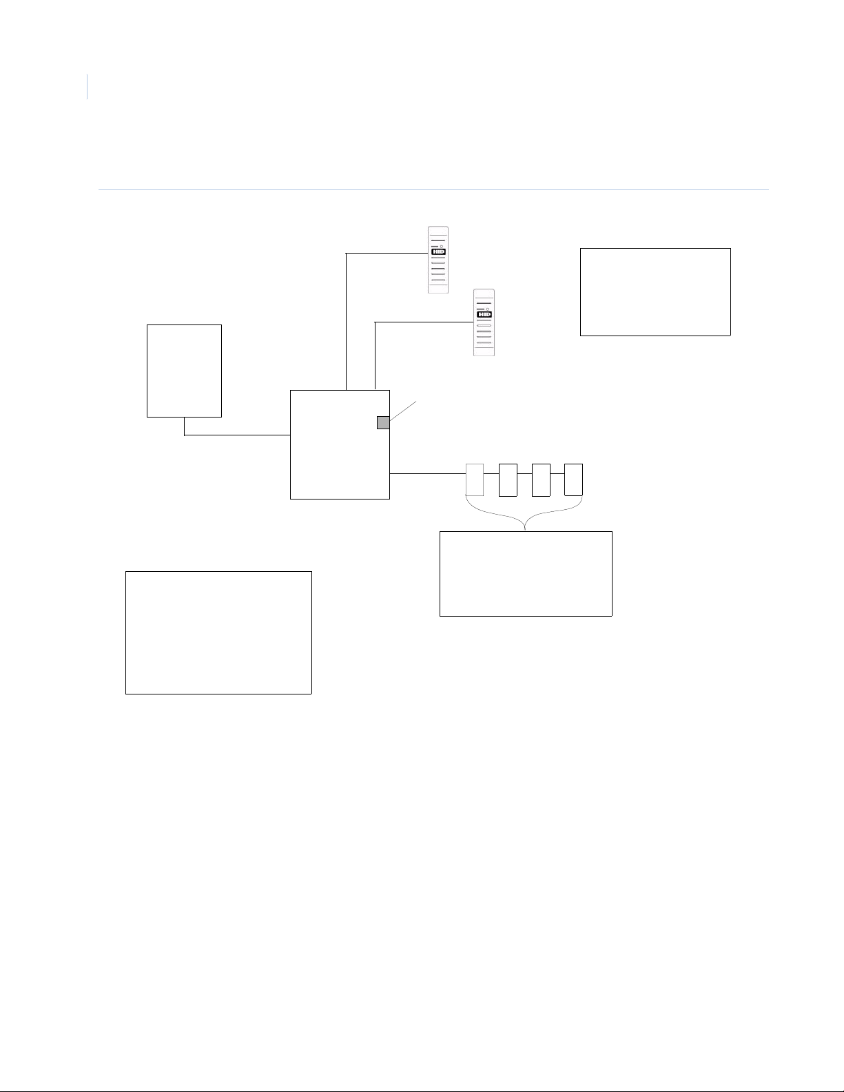
ACURT2 System Diagram
Figure 2. ACURT2 Block Diagram
Host
PC
Host Port
ACURT2
Expansion
Port
Ethernet
Port
Reader 0
Reader 1
These readers use the on-
board alarm inputs and
relay outputs for door
monitor, REX, and lock
7
654
Features
1 - Host Port (RS-232 or RS-485)
1 - Ethernet Port
2 - Reader Support
1 - Expansion Module Port
for up to 4 RRMs or RIMs
6 - Alarm Inputs
4 - Relay Outputs
Combination of up to four RIMs
and/or RRMs may be connected
to the Expansion Port using
address 4, 5, 6, & 7
Page 21
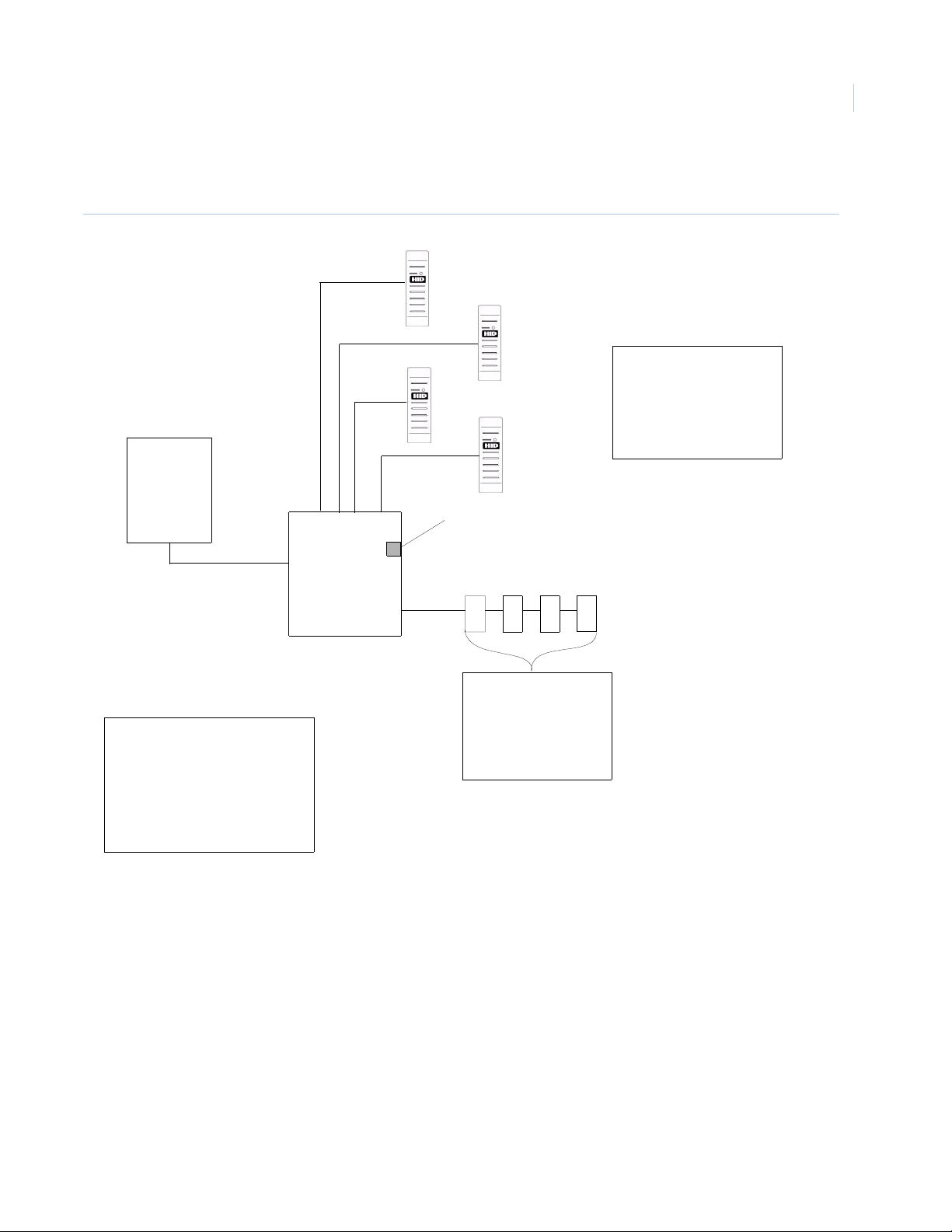
ACURT4 System Diagram
Figure 3. ACURT2 Block Diagram
Host
PC
Host Port
ACURT4
Reader 0
Reader 2
Ethernet
Port
Reader 1
Reader 3
The TOPAZ ACURT
These readers use
the on-board alarm
inputs and relay outputs
for door monitor, REX,
and lock
Chapter 1
5
Expansion
Port
Features
1 - Host Port (RS-232 or RS-485)
1 - Ethernet Port
4 - Reader Support
1 - Expansion Module Port
for up to 4 RRMs or RIMs
12 - Alarm Inputs
8 - Relay Outputs
7
654
Combination of up to four
RIMs and/or RRMs may be
connected to the
Expansion Port using
address 4, 5, 6, & 7
Page 22

TOPAZ ACURT2 & ACURT4
6
Hardware Installation Guide
Page 23

Chapter 2 Installing the ACURT Panel
In this chapter you will learn the basics of installing and wiring the ACURT2 and
ACURT4 panels. This includes:
Running the Wire and Cable . . . . . . . . . . . . . . . . . . . . . . . . . . . . . . . . . . . 8
RS-485 Communications. . . . . . . . . . . . . . . . . . . . . . . . . . . . . . . . . . . . . . 9
Pulling Wire and Cable. . . . . . . . . . . . . . . . . . . . . . . . . . . . . . . . . . . . . . 10
Network Communications. . . . . . . . . . . . . . . . . . . . . . . . . . . . . . . . . . . . 13
Installing UPS Batteries . . . . . . . . . . . . . . . . . . . . . . . . . . . . . . . . . . . . . 22
Dial-up Modem. . . . . . . . . . . . . . . . . . . . . . . . . . . . . . . . . . . . . . . . . . . . 23
Installing Server External Modem . . . . . . . . . . . . . . . . . . . . . . . . . . . . . 26
Terminal Connector Pin Numbers . . . . . . . . . . . . . . . . . . . . . . . . . . . . . 29
Wiring the Host Communications. . . . . . . . . . . . . . . . . . . . . . . . . . . . . . 40
Page 24

TOPAZ ACURT2 & ACURT4
8
Hardware Installation Guide
Running the Wire and Cable
The procedure for running the wire and cable is described in the following paragraphs.
Note:
1. In running wire and cable, be sure to observe and follow applicable building codes.
2. The dry relay contacts are rated at 2 amps at 30 AC/DC volts.
3. All wires should be stranded.
4. The maximum length of the wiring between the farthest Remote Module (RIM, or RRM) and the
ACURT controller is 4000 feet (1220 meters) provided the remote module is locally powered.
5. Guard against lightning damage.
6. All bare Shields should be taped or protected against accidental shorting against electronic
components.
Page 25
Installing the ACURT Panel
Chapter 2
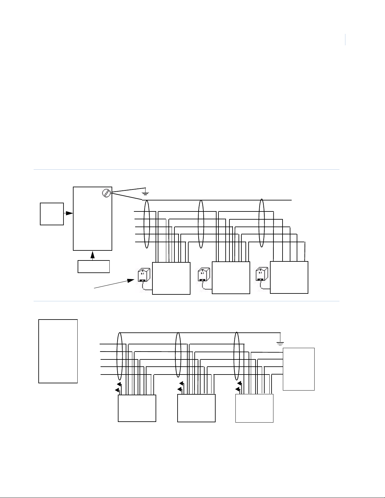
RS-485 Communications
RS-485 is a differential voltage communication circuit. The impedance is 120 ohms. End-of-line terminators
are required on bot h ends of t he communica tions path. Multi- drop c onfigur atio ns are all owed wit h a maxi mum
length of 4000 feet. Off the RS-485 cable, stubs can be dropped, but the length of any stub should not be
longer than 10 feet. Stubs can connect to ACURT controllers or remote modules (RIM or RRM). Stubs must
not be terminated. We strongly recommend star configurations be avoided. (See figure 4)
The ACURT2 and ACURT4 controllers are switch selectable for RS-485 termination on each host and
expansion module port.
The GE Security ACURT2/ACURT4 requires a RS-485 terminator at the NCIC-5 RS-485 converter. See
Figure 13 and 14.
Figure 4. RS-485 Communication Wiring for ACURT2 and ACURT4.
Connect earth ground via stud in ACURT box. See page 7
9
From
Server
NCIC-5
RS-485
converter
- GND
- RDB
- RDA
- TDB
- TDA
12 VDC
AC Plug-In
Power Supply
Figure 5. RS-485 Communication Wiring for Remote Modules
Signal T+ R+
Ground
ACURT2/RT4
SIG
ACURT
- GND
Expansion
Module
Port
- RX+
- RX-
- TX+
- TX-
* Aux
Power
+
+24 T R+
0v T- R-
Power
* Aux
T- R-
+
+24 T+ R+
0v T- R-
Signal T+ R+
Ground
T- R-
ACURT2/RT4
* Aux
+
Power
+24 T+ R+
0v T- R-
Signal T+ R+
Ground
T- R-
ACURT2/RT4
Connect to
earth ground
via stud in
ACURT box
See page 7
Terminate
using DIP
switch or
RS-485
terminator
PN 124824
RIM or RRM
RIM or RRM
RIM or RRM
Notes:
• If Auxiliary power is not provided locally, another pair of wires will be required to each RIM / RRM.
• Shield refers to the over all braided shield, GND refers to the shield drain wire. Transmit should use
one twisted pair and receive should use the other twisted pair.
Page 26

TOPAZ ACURT2 & ACURT4
10
Hardware Installation Guide
Pulling Wire and Cable
Pull the wiring to the remote module from the ACURT controller.
All the wires except the strike pair may be run as one cable. The cable should have low-capacitance twisted
pairs and a shield. At tach pigtail to shield and con nect t o chassis ground. The following Belden cable numbers
(or equivalent) are suggested:
Belden No. 9842-24 AWG for 1000 feet (305 meters) maximum distance
Pull a single pair of wi res from th e enclosur e to the el ectric do or strik e. The follo wing Belden ca ble number (o r
equivalent) is suggested:
Belden No. 9409-18 AWG
Pull the wires to the enclosure from each alarm zone sensor, door contact and exit push button. The following
Belden cable number (or equivalent) is suggested:
Belden No. 9407-22 AWG
Pull the wires to th e enclosure from passive exit dev ic e i f t he device requires power, otherwise use cable lis te d
above. The following Belden cable number (or equivalent) is suggested:
Belden No. 8741-22 AWG
Baud Rates and Distances
The information in the table below may vary according to the quality of the cable used and the number of
panels in a chain.
Table 2. Recommended baud rates
Baud rate Distance
115,200 75 to 100 feet
(23 to 30.5 meters)
57,600 800 to 1000 feet
(244 to 305 meters)
38,400 1000 to 3000 feet
(305 to 915 meters)
Grounding Connections
It is important to connect each ACU panel on the communication loop individually to earth ground, not to
chassis or electrical ground. Grounding is imperative for proper data communications between panels and to
ensure full functionality of the lighting and transient voltage protection devices. Voltage protection device are
designed into all ACU panels and will channel most transient surges to ground if the panel is properly
connected to earth ground. If the panels are not properly connected to ground, the surge suppression devices
may not function and data communications may be erratic.
Page 27

Installing the ACURT Panel
Chapter 2
For proper grounding all ACUs should be connected to earth ground, not to chassis or electrical ground. Cold
water pipes or a grounding rod usually make a good earth ground. The grounding wire should be as heavy as
possible with as short and straight a run as pos sible . Avoid sharp bends in the wi re beca use a l ar ge power surge
might arc across the board.
Recommended Grounding Sources
• Cold Water Earth Ground
• Building Ground
• Electrical Ground
The GE Security system should use a consolidated earth ground, in which the public utilities and the security
system ground rods are bonded together. A consolidated earth ground eliminates the problem of step voltage
blowout, in which measurable voltage potential exists between earth ground rods, resulting in a current flow
path and damage to the system during a lighting strike.
It is recommended that 12 AWG wire be used to connect the earth ground in the shortest and straightest path
possible. Avoid sharp turns and use a minimum radius of eight inches (203 mm) for bends. Ground wires
should be run separate from other wires and be routed toward the earth. Use of eight-foot (2.4 m) copper clad
ground rod is recommended.
11
Alarm Zone Sensor Wiring
Pull twisted pair of wire (Belden 9407-22 AWG or equivalent) from each alarm zone sensor to the assigned
input terminals on the ACURT controller or Remote Module (RIM). (See Terminal Block Tables in each
section for alarm zo ne termina tions.) End-o f-line ( EOL) resis tor for the SECURE state i s 1000 ohms. The EOL
(End-Of-Line) resistor must be located within the alarm zone sensor enclosure, otherwise the alarm zone
circuit will be considered unsupervised.
When 1000 ohms terminators are used, the sensors can be either normally closed contacts or normally open
contacts providing the SECURE or inactive state is 1000 ohms. See Figure 6. (Note: A normally open exitpush-button is wired the same as a normally closed alarm).
Table 3. Alarm State Resistance
Sensor Circuit in Ohms
Zone Input State
Secure 1000 1000
Active 2000 500
Open > 50000 > 50000
Short < 50 < 50
Normally Closed
Sensor Circuit in Ohms
Normally Open
Page 28
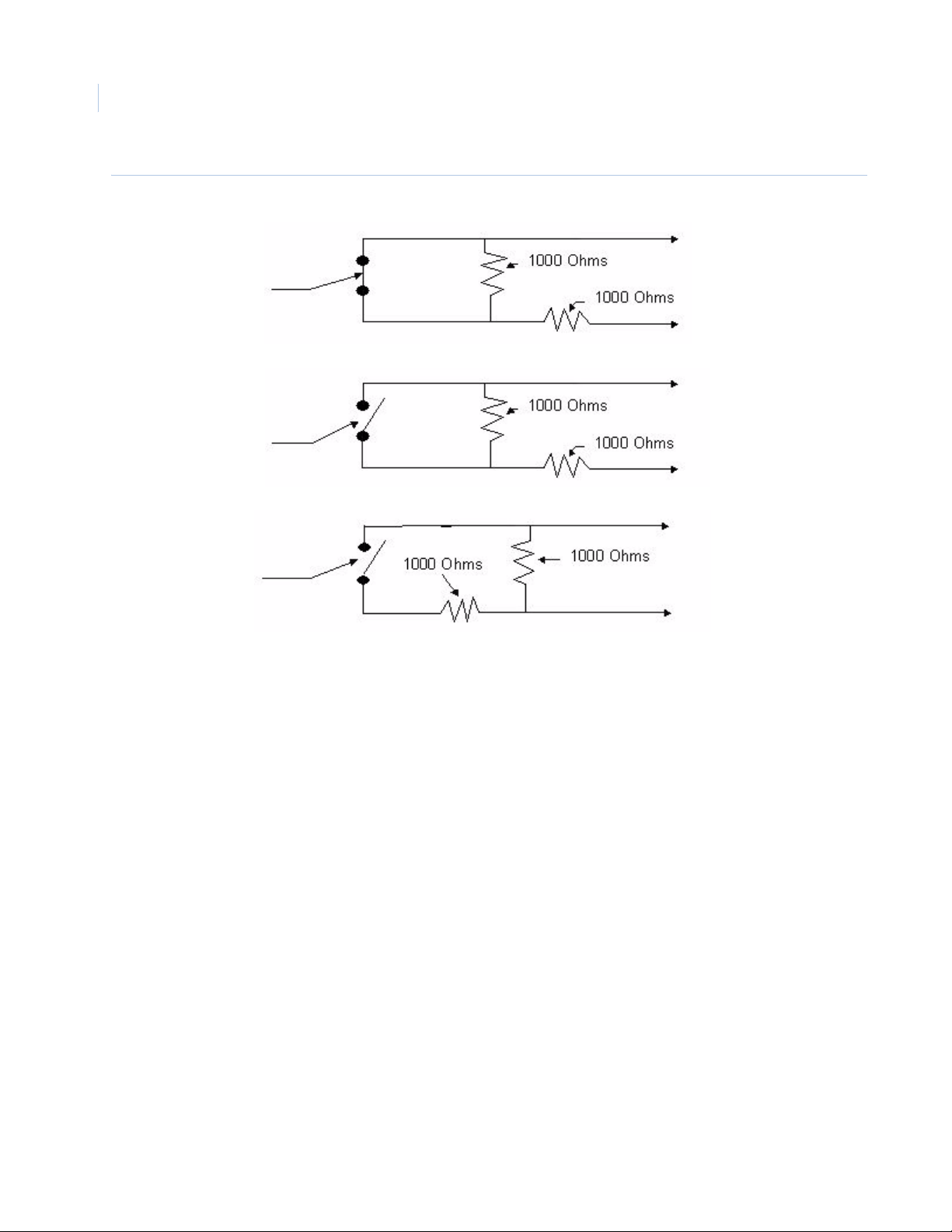
TOPAZ ACURT2 & ACURT4
12
Hardware Installation Guide
Figure 6. Zone Sensor with 1000-Ohm Resistors
Normally Closed
Sensor
Normally Open
Exit Push Button
Normally Open
Sensor
Z+
Z-
Z+
Z-
Z+
Z-
Page 29

Installing the ACURT Panel
Chapter 2
Network Communications
This section provides guidelines for the network env ironment needed t o support communication betwee n a GE
Topaz Server and ACU Ne tworked Intell igen t Controller Field Panels. While it is not possible to address every
variable that may exist in a custome r’s network e nviro nment, t his hi ghlight s key ne twork c onside ration s.
The information in the following table is assuming a minimum T opaz server software revision of 1.47 and a minimum
ACURT panel firmware revision of 7.13.00
Table 4. Network communications guidelines
Port The TCP/IP port number that the ACU panel listens to is 3000 plus the system WAN number (typically 3001).
Protocol TCP/UDP
All messages are less than 255 bytes. The protocol is a simple command and response protocol with a
sequence number retry mechanism.
13
Timing Polling
Frequency
Server Wait
and Delay
Time
Server Retry If the server does not receive a response from the panel within the delay time described
Panel
Timeout
Timing
Calculations
400 milliseconds per ACU panel (fixed)
Wait time for the server to receive a response is 500 milliseconds. Networks should be able
to respond to a ping for each panel within 500 milliseconds for optimum performance.
Additional user-configurable delay time of up to 3000 milliseconds can be set for each
panel. Typical additional delay is 500 milliseconds.
above, the server will re-send another poll to the panel. The default number of retries is 3.
The Retry for each panel can be increased up to 10 by the system administrator. Setting the
number of retries above three is usually for testing purposes only, and not intended for
normal operation of the system.
If a panel does not receive a correct message from the server within 10 seconds, the panel
will no longer respond to the server (a “local panel off-line” condition). This could be caused
by a network interruption or incorrect message(s). An example of an incorrect message
might be if the network corrupts a server message, resulting in a checksum error. This
causes the server to resynchronize communications with the panel. A corresponding
message will be reported at the server as a “panel off-line”.
To determine proper panel settings for optimal communication, perform the following
calculations for each panel. The total delay, including retries, should be less than 10 seconds
(Panel Timeout); The lower the total, the more optimal system performance.
ACU LAN Panel with no downline panels via serial connection:
#Retries X [Delay Time(secs) + Wait Time(secs)] = Total
For example: 3 X [1.2 + 0.5] = 5.1
ACU LAN Panel hosting down-line panels via serial connection:
#Down-line panels X #Retries X [Delay Time(secs) + Wait Time(secs)] = (Total)
For example: 3 x 3 x [0.5 + 0.5] = 9
Bandwidth
Dynamics
Network Hops To ensure consistency, the number and distance of hops between a field panel’s LAN port and it’s hosting
It is important that allocated bandwidth remains consistent at all times and is not clamped down (or
reduced) during off-hours such as at night or on weekends. Inconsistent or dynamic bandwidth can result in
inconsistent on-lin/off-line behavior of field panels, especially if network throughput is marginal.
server should be kept to a minimum.
Page 30

TOPAZ ACURT2 & ACURT4
14
Hardware Installation Guide
Table 4. Network communications guidelines (continued)
Download
Activity
ACU
Comparison
Two types of download activity can occur: Full panel downloads or smaller downloads that occur during
routine use of the system. During the download operation, the ACU is fully operational after power-up.
Access requests are processed and normally, little delay is experienced. However, large amounts of activity
have an adverse effect on system performance.
A full panel download can be initiated manually by the system administrator, or automatically when:
• A panel is powered-up or reset
• A change is made to Access Groups
• A panel definition is modified
• A new reader is defined
• An elevator floor definition is modified.
Note: During a full panel download, the entire card database is downloaded to the panels, however only
those cards which are authorized for access through doors controlled by a panel are downloaded
to that panel, thus reducing per-panel traffic.
Following a server restart, all alarm points, relays, time schedules, and other user-programmed settings and
parameters are downloaded. The card database is only downloaded if, after a comparison, the server
detects that cardholder changes were made at the server but not updated to the ACU.
If an initial download from the server to the ACU is interrupted, the ACU waits for the download to restart.
Note: ACU2X: After a successful download, the ACU2X saves the count of cards in its database. If a
subsequent full card download is interrupted, the panel restores the original pointers so that a
backup mechanism exists until a successful download is achieved.
The ACU2XL, ACURS, and ACURT panels are approximately 100 times faster for communication that an
ACU2 or ACU2X panel with the LanTronix kit. This is because a panel using the LanTronix kit connects to the
kit from the panel serial port that runs at an average of 9600 baud, whereas the ACU@XL, ACURS, and
ACURT panels run at the 10 Mbps rate of their built in network card.
Setting IP Address
If the installation requires UL Listing, Network connections cannot be used.
One of the simplest ways to set the IP address on the ACURT2 or ACURT4 is with a laptop computer in the
field running the AcuxUtil.exe program.
If using the default IP address (SW3 switch 3 on) attach and configure only one ACURT at a time.
Page 31

Installing the ACURT Panel
Chapter 2
To set up the TCP/IP address for an ACURT field panel start by locating the AcuxUtil.exe file on the CD and
start the utility by double-clicking on it’s icon.
After starting the utility the following screen is displayed.
15
Set IP Address Through Ethernet
Before continuing make sure your PC has a network card installed with TIP/IP enabled. The IP address must
able to communicate to the ACUR T. In other words, the first three sets of numbers of the computer’s IP address
must match the first three sets on numbers of the ACURT IP address. The default IP address of the ACURT is
192.168.0.132
1. Click the Ethernet button.
Page 32

TOPAZ ACURT2 & ACURT4
16
Hardware Installation Guide
2. Make sure that SW3 DIP switches 1, 2, and 3 are ON before continuing.
Note: If you change switch settings, you must restart the ACU by powering down and back up.
3. You must also know the IP a ddress of t he ACURT before continuing. If yo u do not know the current IP
address for the ACURT, turn SW3 switch 3 ON to use the default IP address of 192.168.0.132.
4. Power must be cycled on the ACURT for the switches to be read.
5. After the switches are set properly, click OK.
The IP Address of the ACURT has been set at the factory to a default of 192.168.0.132.
6. Enter the IP address for the A CURT
7. The Port Number will be left at the default 3001 unless you have multi servers on your system. If
using multi server change the last three digit (3000 plus the LAN number) of the Port Number to
reflect the server number. For server number two the Port Number would be 3002.
8. Click O
K to continue.
Page 33
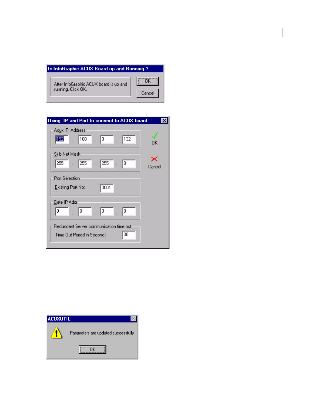
Installing the ACURT Panel
9. Click Start button to start the configuration of the IP Address.
10. Make sure SW3 DIP Switches 1 and 2 are turned ON at the ACURT and click OK.
Chapter 2
17
The addresses for this screen must be obtained from your MIS department.
11. Enter the new ACURT IP Address, Sub Net Mask, Gate IP Address, (Gateway or Router) .
12. The Existing Port No. will be left at its default 3001 unless you have multi servers on your system.
Change the last three digit of the Port No. to reflect the server number (3000 plus the LAN number).
For server number two the Port No. would be 3002.
13. The Time Out Period is used for redundant systems only. The default is 30 Sec.
14. Click OK to continue.
15. The ACURT was updated successfully.
Page 34
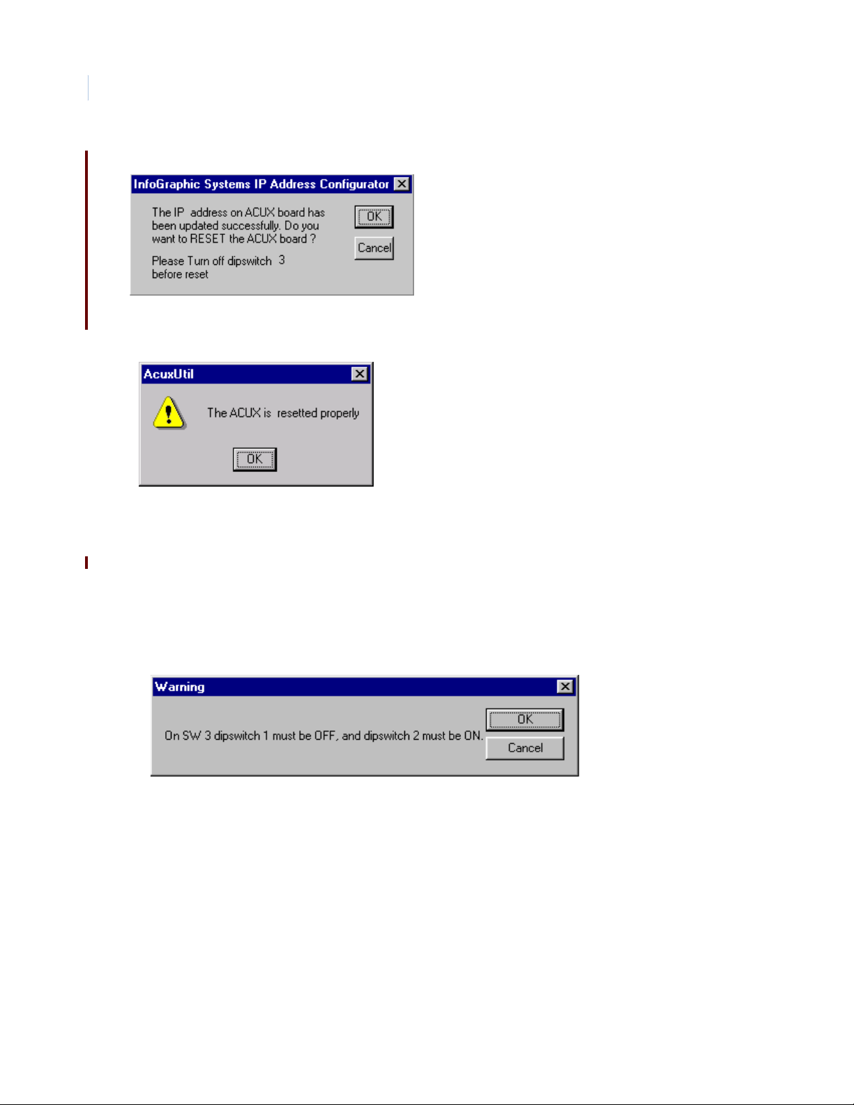
TOPAZ ACURT2 & ACURT4
18
Hardware Installation Guide
16. Click OK to continue.
17. Before continuing, make sure DIP switch 3 at the ACURT is turned OFF.
18. Click OK to continue and reset the ACURT.
The ACURT has been updated with the new IP address.
19. Click OK to complete the setup.
Note: The panel will ping at 100mbsp, but it will only come online at 10mbsp.
Set IP Address Through Serial Connection
The ACURT must be able to connect to the computer and power to the ACURT must be turned on.
1. Click the Serial button.
2. Turn SW3 DIP switch 1 OFF and 2 ON at the ACURT.
3. Power must be cycled on the ACURT for the switches to be read.
Page 35
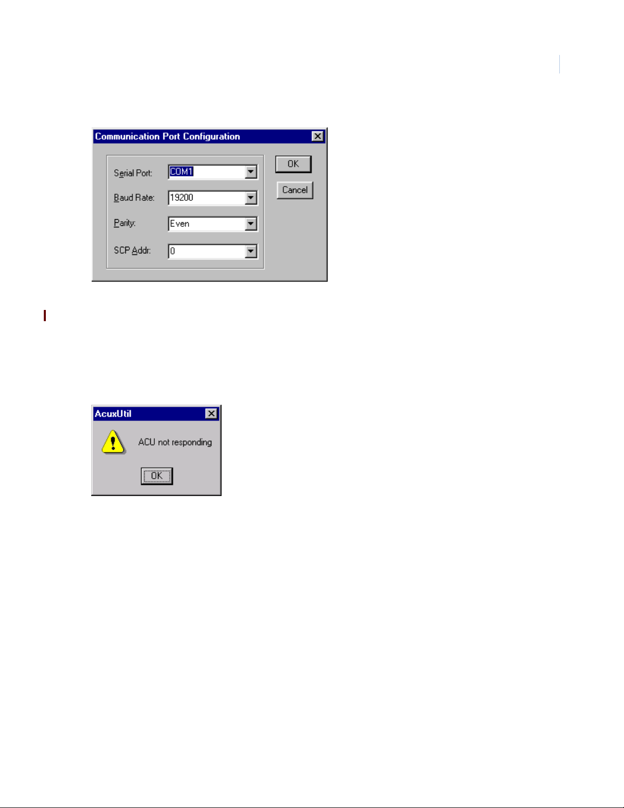
4. Click OK to continue.
5. Select the Communication port that the ACURT is connected to.
6. Select the Baud Rate that the ACURT set to communicate at. The default is 9600.
7. Parity should be left at Even.
8. The SCP Address is the communication address the ACURT is set at with SW4.
Installing the ACURT Panel
Chapter 2
19
9. Click OK.
If the ACURT is not communicating the following message will appear.
10. Click OK and check your Serial connection and try again.
Page 36
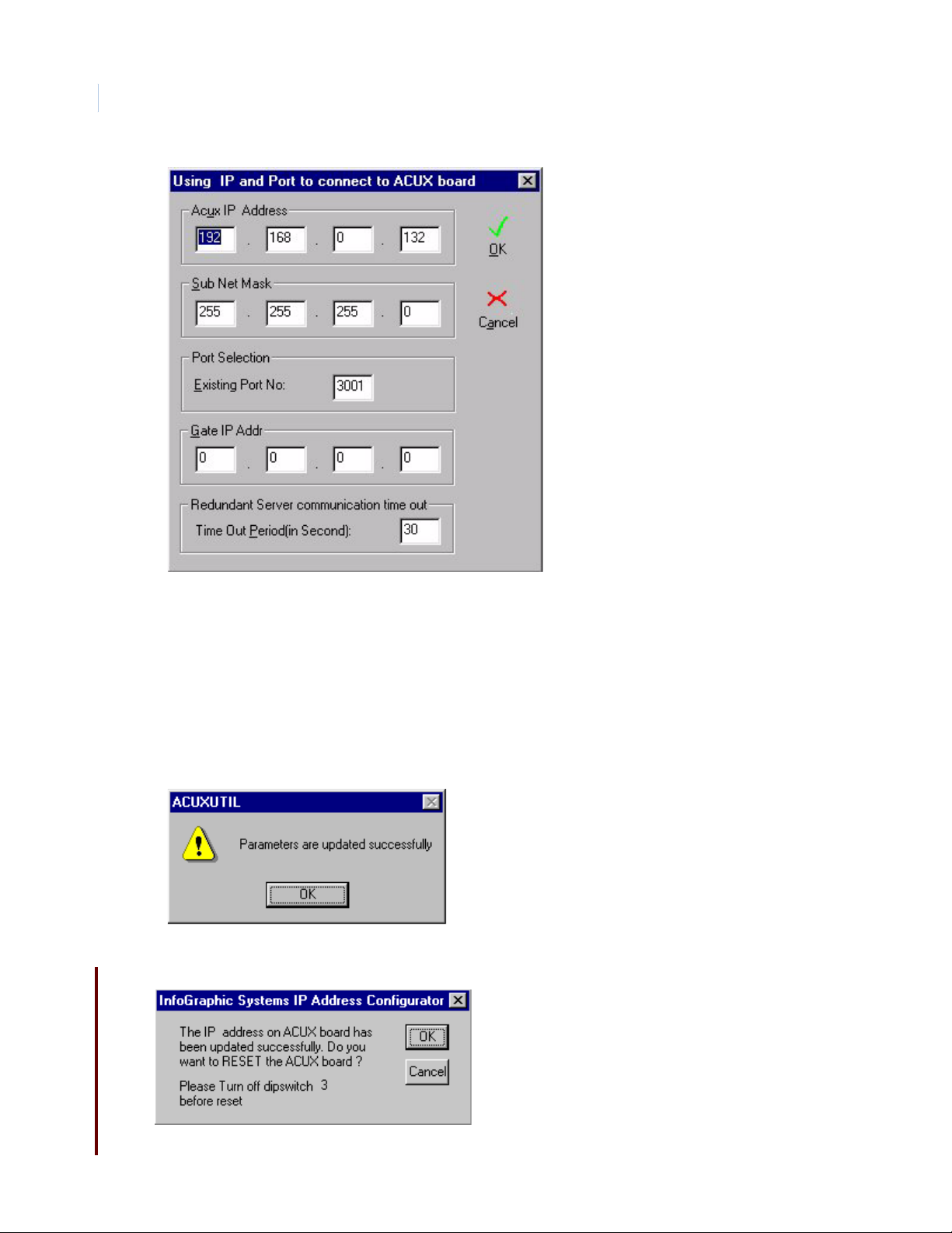
TOPAZ ACURT2 & ACURT4
20
Hardware Installation Guide
The addresses for this screen must be obtained from your MIS department. The IP Address of the
ACURT has been set at the factory to 192.168.0.X. The X number is different for each ACURT.
11. Enter the new ACURT IP Address, Sub Net Mask, Gate IP Address, (Gateway or Route r) .
12. The Existing Port No. will be left at its default 3001 unless you have multi servers on your system.
Change the last three digit of the Port No. to reflect the server number (3000 plus the LAN number).
For server number two the Port No. would be 3002.
13. The Time Out Period is used for redundant systems only. The default is 30 Sec.
14. Click OK to continue.
15. The ACURT was update successfully.
16. Click OK to continue.
Page 37
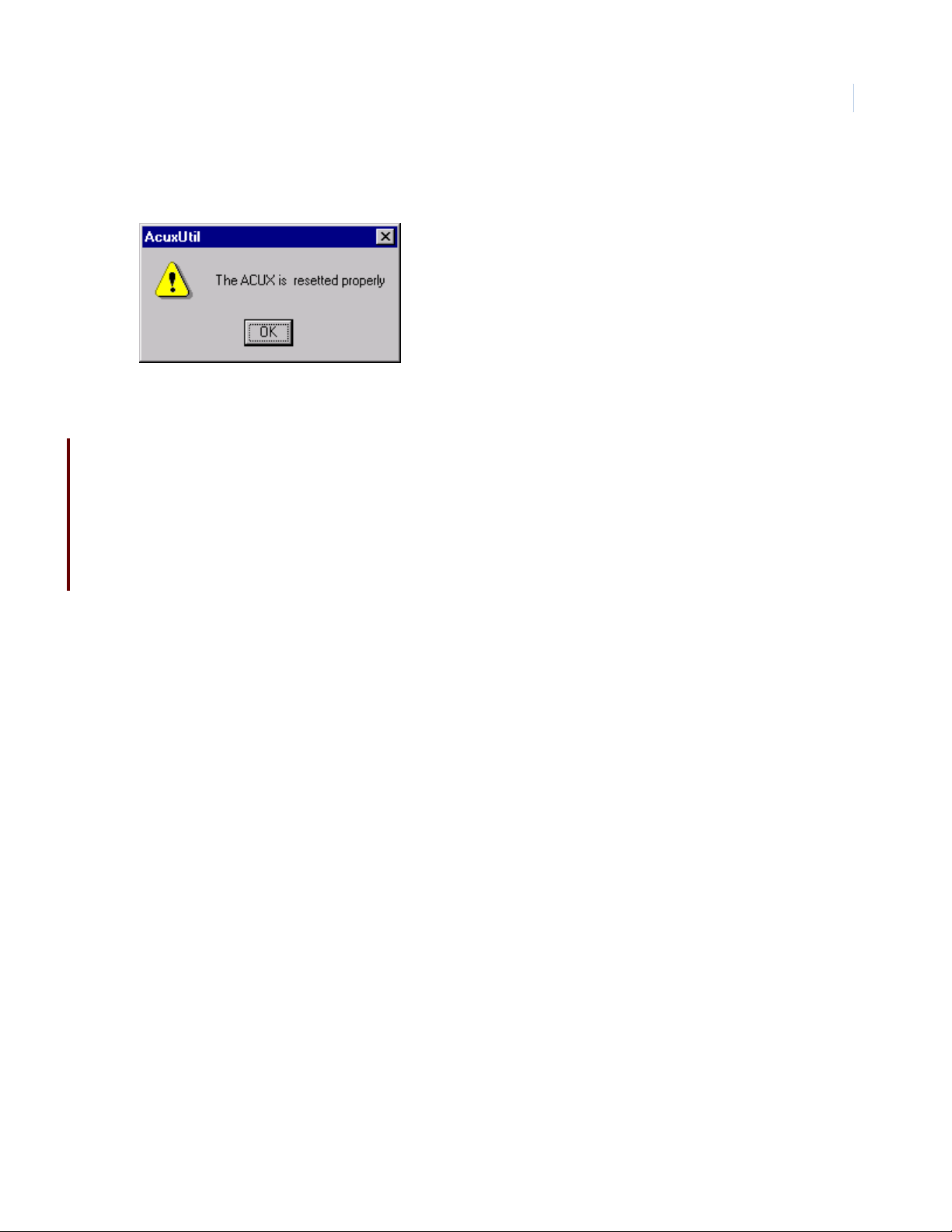
Installing the ACURT Panel
17. Before continuing, make sure DIP switches 2 and 3 at the ACURT are turned OFF.
18. Click OK to continue and reset the ACURT.
The ACURT has been updated with the new IP address.
19. Click OK to continue.
Note: The panel will ping at 100mbsp, but it will only come online at 10mbsp.
Determining the MAC address
The IGS IEEE assigned MAC address for the ACU XL LAN unit is: 00 06 0e 00 00 00
Chapter 2
21
where the last 4 digits are the serial number in hexadecimal.
For example, a serial number of 1000 would be: 00 06 0e 00 03 e8
Page 38

TOPAZ ACURT2 & ACURT4
22
Hardware Installation Guide
Installing UPS Batteries
WARNING: Be sure to observe battery manufacturer's instructions:
• Danger Explosive Gases
• Can cause blindness or severe injury.
• Use in a well ventilated area away from open flame, cigarettes, sparks, and other sources of ignition.
• Shield eyes and face when working around battery.
• Do not make direct contact between the positive and negative terminals.
• Do not puncture, disassemble, or incinerate batters.
• Dispose of in accordance with environmental regulations.
Poison - contains lead compounds and corrosive acid.
Contains sulfuric acid which can causes severe burns. In the event of contact, flush with water and obtain immediate
medical attention.
Keep out of reach of children.
Charge in accordance with manufacturer's instructions.
WARNING: Make certain that the AC power source circuit breaker(s) is OFF before proceeding. Failure to heed this
WARNING can cause death, personal injury, or damage to unit(s).
CAUTION: To avoid an electrical short, do not let the contacts on the batteries touch any part of the enclosure or
mounting plate.
Installing and Connecting
The UPS battery installation and wiring connection to the assembly is made as follows:
1. Place the two 12 VDC rechargeable batteries in the bottom of th e cabinet.
2. Connect the battery cables (AFTER all other wiring is connected) to the battery to TB10 terminal 6
(Battery, 24V+) and terminal 7 (Battery, 24V-).
3. The operating voltage of the batteries will be approximately 27.5 VDC. When the battery voltage
drops to 24 VDC the ACURT will generate an AC Fail alarm and when the voltage level drops to 21
VDC it will generate a Low Battery alarm.
Note: If the ACURT is to be powered from a 27.5 VDC UPS, connect the output of the power source to the battery connection
on the ACURT, TB10-6(+), and TB10-7(-). The 24 VAC plug in transformer and internal ACURT UPS batteries are no longer
required.
Page 39

Installing the ACURT Panel
Chapter 2
Dial-up Modem
Installing Dial-up Modem
If the installation requires UL Listing, the Dial-up modem cannot be used.
The Dial-up modem allows the TOPAZ server to communicate over standard dial phone lines to the ACURT2
and ACURT4 when LAN or direct connections with RS-232 and RS-485 are not available.
The modem board mounts o n the ACURT board near the top by pl ugging th e J1 connec tor on t he modem bo ard
into the PJ1 connector on the ACURT board, as shown below.
Figure 7. Dial-up Modem Installed on Top of the ACURT Board
Modem board installed
on the ACURT
23
Install the modem board by aligni ng connectors JP1 and J1 and the four (4) plastic stand offs (already installed
on the modem board) with the holes on the ACURT board. While making sure that connectors J1 and JP1 are
lined up, gently snap the standoffs into the holes.
Note: When using dial-up modems the baud rates MUST be set to 9600 with no parity. Also a Robotics Sportster external
modem (Model 0459 or 0701) must be used at the host computer. See Installing Server External Modem later in this
chapter for more details.
WARNING: Make certain that the AC power source circuit breaker(s) is OFF before proceeding. Failure to heed this
WARNING can cause death, personal injury, or damage to unit(s).
Page 40
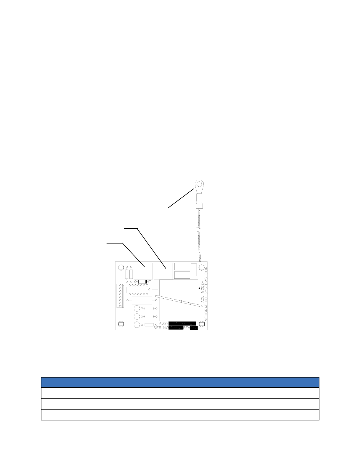
TOPAZ ACURT2 & ACURT4
24
Hardware Installation Guide
Connecting the Dial-up Modem
After installing the modem board connect the frame gro und wi r e t o t he g rounding lug in the cabinet just a bove
the board. See Figure see page 27.
Connect the modem to a stan dard di al type telep hone li ne by plug ging th e phon e line ’s RJ45 connector into J3.
A telephone instrument for testing can be connected to J2.
Note: DO NOT use PBX or Key Switch type phone lines.
SW2 on the ACURT2 or ACURT4 should be set as follows: 1,2,3, 5, and 8 set to “ON”.
The Topaz systems administrator will need to know the ACURT2 or ACURT4 Controller’s Serial Number.
Component Layout
Figure 8. Component Layout of the Dial-up Modem Board
To Frame Ground
J2 - To: Phone (for testing)
J3 - To: Phone Line
J3
J1
8
LED1
1
LED3
LED2
J2
LEDs on Modem Board
The LEDs will show the modem status and help in trouble shooting the modem.
Table 5. Dial-up Modem LED Indicators.
LED’s on Modem Description
LED1 Power - Lights when modem is “powered”.
LED2 Ring Detect - Lights when the modem has called.
LED3 Carrier Detect - Lights when the Modem has established communication with the host modem.
Page 41

Installing the ACURT Panel
Chapter 2
Connecting (MDD) Multi-Drop Dial-Up Panels
The dial-up ACURT panel may have up to 14 additional ACURT panels multi-dropped to its RS485 port as
shown below. The additional panels must be configured in Topaz software as dial-up panels with the same
phone number as the ACURT panel with the dial-up modem card installed.
Note: DO NOT use PBX or Key Switch type phone lines.
Figure 9. RS485 Port Wiring For Multi-Drop Dial-Up Panels
ACURT
Address 15
1 Sig GND
6 TX+
7 TX 8 RX+
9 RX -
Up to 14 panels may be
added to the loop
1 Sig GND
6 TX+
7 TX 8 RX+
9 RX -
ACURT
Address 2
1 Sig GND
6 TX+
7 TX 8 RX+
9 RX -
ACURT
Address 1
1 Sig GND
6 TX+
7 TX 8 RX+
9 RX -
Dial-Up
Phone Line
Connection
25
Last panel in loop
must be terminated
4,000 feet maximum
In the above configuration the panel with the dial-up modem installed must be set as address “1” and each
additional panel on the RS485 port must be addressed starting with “2” then “3” and so on up to address 15.
Modem Board Replacement
Make sure that power is removed from the ACURT before removing the modem board. Disconnect the phone
lines(s) from the modem. While squeezing the tip the standoff, protruding through the board with a pair of
needle nose pliers , gently lift the modem board of f of the plastic standoff s. Unplug the board from the ACURT.
While aligning the new board wit h the J1 an d JP1 connec tors, gently sn ap t he board on to the pla stic standof fs.
Plug the phone line back into J3. If there was a telephone instrument (for testing) connected, plug it back into
J2.
Page 42

TOPAZ ACURT2 & ACURT4
26
Hardware Installation Guide
Installing Server External Modem
When using Dial-up communications to an ACURT field panel you must install an external modem at the
server. The Topaz Software will ONLY support the (USR) US Robotics 33.6 faxmodem or the 56K V.90
faxmodem, Sportster modem models 0701 (005686-03) or 0459 (00083907).
Model information located on the back of the modem near the FCC logo sticker, there are some numbers,
model #0459 and Sportster 0083907 (the current model is 000839-09 from the USR web site). The 56K V.90
faxmodem can also be used. The number on the back is model #0701 Sportster 005686-03 (USR5686E from
the web site) .
Note: DO NOT use internal modem cards or external modems without dipswitchs.
Information on these modems may be found at the US Robotics web site, www.usr.com. Click on U.S./
Canada (English), then click Search Site tab at the top of the page, then type sportster 005686-03 or
sportster 00568 into the search field.
External Modem Setup
The switches on t he bac k of t he modem must be con figur ed wit h swit ches 5 and
6 set to the UP position, all others should be in the down position as shown to
the right.
Note: You will NOT need to install the modem or drivers in Windows.
When you power up the external modem LEDs AA, TR, and CS should be illuminated, all other should be off.
Software Setup
After installing the modem make sure dial-up panels are configured in the Topaz server software as SCP DialUp, set to 9600 baud, No parity and Active.
From Control and Service Functions, you must setup the modem. Choose Initialize - Test Modem and Serial
Port and say Go. The modem LEDs SD and RD should blink several time. This sends the correct AT
commands necessary for the modem to work correctly.
Note: It is recommended you use a minimum of two dial-up ports/modems for data and alarms. As the system grows or as
the alarm load increases, it may be necessary to use more Server modems to handle the traffic.
The Topaz systems administrator will also need to know the ACURT2 or ACURT4 Controller’s Serial
Number.
Troubleshooting
Be sure the external dial-up modem at the server is connected correctly.
Check the dial-up modem board in the ACURT to make sure it is firmly install on the pins J1 and no pins are
bent over.
Make sure the ACURT modem board is properly grounded.
You may have to clear memory on the ACURT board.
Note: Be aware this action will leave the ACURT without any configuration.
Page 43

ACURT2 and ACURT4 Enclosure Layout
Figure 10. Components Mounted Inside the ACURT Controller Enclosure
Installing the ACURT Panel
Chapter 2
Grounding Stud
(Connect to earth
ground) see page
10
27
Tamper
Switch
Page 44

TOPAZ ACURT2 & ACURT4
Attach t
28
Hardware Installation Guide
ACURT2 and ACURT4 Component Layout
Figure 11. ACURT2 and ACURT4 Component Layout
LAN Port
1
9
1
8
1
8
1
3
TB1
TRANSMIT DATA LED
HOST PORT
RECEIVE DATA LED
TB2
TB3
READER 0, ZONE 0 LED
READER 0, ZONE 1 LED
READER 0, ZONE 2 LED
TB4
READER 0, DOOR
STRIKE RELAY LED
ON
^
I
1
SW1
1
4
TB8
TX
EXP. MODULE
COMMUNICATION
LEDS
RX
LAN Status
LEDs
5
J1
+3.3VDC
AC ON
STATUS LEDS
1234
Optional dial-up
Modem Card
TX
RX
COL
J1
LINK
REV
+5VDC
JP1
+12VDC
SW4
1
J3
J2
8
LED1
LED3
LED2
4
8
0
^
I
C
1818
SW2
U12
SW3
ON
^
I
READER 2, ZONE 0 LED
READER 2, ZONE 1 LED
READER 2, ZONE 2 LED
READER 2, DOOR
STRIKE RELAY LED
SW7
POWER
SWITCH
o
Grounding Stud in
Panel see page 10
TB10
TB11
TB12
TB13
TB14
1
7
1
3
1
8
1
8
1
3
NiCad Pack
Voltage
TB5
1
GE Security
8
1
TB6
READER 1, ZONE 0 LED
READER 1, ZONE 1 LED
6
1
3
READER 1, ZONE 2 LED
TB7
READER 1, DOOR
STRIKE RELAY LED
1
SW5
READER 0 AUX.
RELAY LED
TB9
ON
^
I
6
1
READER 1 AUX.
RELAY LE D
BT1
READER 2 AUX.
RELAY LE D
TB18
6
1
READER 3 AUX.
RELAY LED
6
BT2
READER 3, ZONE 0 LED
READER 3, ZONE 1 LED
READER 3, ZONE 2 LED
ON
READER 3, DOOR
^
I
6
STRIKE RELAY LED
1
SW6
TB15
TB16
TB17
1
8
1
8
1
3
Page 45

Installing the ACURT Panel
Chapter 2
Terminal Connector Pin Numbers
Tables 3 through 16 show cable types and connections to terminal blocks TB1 through TB18. Explanations of
the table column headings are as follows:
Table 6. Explanation of Table Headings
Heading Description
29
TB#
Pin#
Terminal Strip ID#
Description
Maximum distance and Belden or
Equivalent Cable #
Identifies the terminal block number on the ACURT2 and ACURT4 circuit board.
Identifies the pin number of the applicable terminal block.
Identifies the abbreviation of the terminal on the printed template.
Identifies the description of the terminal.
Identifies the cable number, the maximum distance when applicable.
Connections for Terminal Block 1
Host Communication Port
Table 7. Terminal Block TB1 Pin Number Identification
Maximum Distance and
TB# Pin# Term. Strip ID Description
1 1 SIG GND Host Port Signal Ground 9608-24 (3 conductor) AWG, 50 feet
1 2 TXD Host Port RS-232 Transmit Data
1 3 RXD Host Port RS-232 Receive Data
1 4 RTS Host Port RS-232 RTS
Belden or Equivalent Cable No.
9609-24 (4 conductor) AWG, 50 feet
1 5 CTS Host Port RS-232 CTS
1 6 TX+ Host Port RS-485 Transmit Data (+) 9842-24 AWG / 9368-18 AWG
1 7 TX- Host Port RS-485 Transmit Data (-)
1 8 RX+ Host Port RS-485 Receive Data (+)
1 9 RX- Host Port RS-485 Receive Data (-)
4000 feet (1220 meters) maximum
Page 46

TOPAZ ACURT2 & ACURT4
30
Hardware Installation Guide
Connections for Terminal Block 2, 3, and 4 (ACURT2 and ACURT4)
Reader 0 Connections
Table 8. Terminal Block TB2, 3, and 4 Pin Number Identification
TB# Pin# Term. Strip ID Description
2 1 +12 VDC Fused 12 VDC Output 9514-22 AWG
2 2 +5 VDC Fused 5 VDC Output
230 V 0 Volts
2 4 DATA 0 Reader Data 0 (Green)
2 5 DATA 1 Reader Data 1 (White)
2 6 RED LED Red LED
2 7 GREEN LED Green LED
Maximum Distance
Belden or Equivalent Cable No.
2 8 BUZZER Buzzer
3 1 Z0+ Normally Closed
32
3 3 Z1+ Normally Open
34
3 5 Z2+ Normally Closed
36
4 1 NC Door Strike Relay Normally Closed 9409-18 AWG (See Warning)
4 2 C Door Strike Relay Common
4 3 NO Door Strike Relay Normally Open
WARNING: DO NOT switch any voltage over 30 VDC on these relays.
Z0-
Z1-
Z2-
Door Contact
Request-to-Exit Contact
Spare Input
9407-22 AWG / 9409-18 AWG
1000 feet (305 meters) / 4000 feet (1220
meters)
9407-22 AWG / 9409-18 AWG
1000 feet (305 meters) / 4000 feet (1220
meters)
9407-22 AWG / 9409-18 AWG
1000 feet (305 meters) / 4000 feet (1220
meters)
Page 47

Connections for Terminal Block 5, 6, and 7 (ACURT2 and ACURT4)
Reader 1 Connections
Table 9. Terminal Block TB5, 6, and 7 Pin Number Identification
Installing the ACURT Panel
Chapter 2
31
Term.
TB# Pin#
5 1 +12 VDC Fused 12 VDC Output 9514-22 AWG
5 2 +5 VDC Fused 5 VDC Output
530 V 0 Volts
5 4 DATA 0 Reader Data 0 (Green)
5 5 DATA 1 Reader Data 1 (White)
5 6 RED LED Red LED
5 7 GREEN LED Green LED
5 8 BUZZER Buzzer
6 1 Z0+ Normally Closed
62Z0-
6 3 Z1+ Normally Open
64Z1-
6 5 Z2+ Normally Closed
66Z2-
Strip ID
Door Contact
Request-to-Exit Contact
Spare Input
Description
Belden or Equivalent Cable No.
9407-22 AWG at 1000 feet (305 meters)
9409-18 AWG at 4000 feet (1220 meters)
9407-22 AWG at 1000 feet (305 meters)
9409-18 AWG at 4000 feet (1220 meters)
9407-22 AWG at 1000 feet (305 meters)
9409-18 AWG at 4000 feet (1220 meters)
Maximum Distance
7 1 NC Door Strike Relay Normally Closed 9409-18 AWG (See Warning)
7 2 C Door Strike Relay Common
7 3 NO Door Strike Relay Normally Open
WARNING: The plug in AC power supply can only be use to power one ACURT board.
Page 48

TOPAZ ACURT2 & ACURT4
32
Hardware Installation Guide
Connections for Terminal Block 8 (ACURT2 and ACURT4)
Expansion Module Communication Port RS-485 Connections
Table 10. Terminal Block TB8 Pin Number Identification
Pin No. Term. Strip ID Description
1 SIG GND Signal Ground 9842-24 AWG
2TX+Transmit +
3TX-Transmit -
4RX+Receive +
5RX-Receive -
Connections for Terminal Block 9 (ACURT2 and ACURT4)
Maximum Distance
Belden or Equivalent Cable No.
4000 feet (1220 meters) maximum
Reader 0 and 1 Auxiliary Relay Connections
Table 11. Terminal Block TB9 Pin Number Identification
Pin
No.
1 NC Reader 0 Aux Relay Normally Closed 9409-18 AWG See WARNING
2 C Reader 0 Aux Relay Common
3 NO Reader 0 Aux Relay Normally Open
4 NC Reader 1 Aux Relay Normally Closed 9409-18 AWG See WARNING
5 C Reader 1 Aux Relay Common
6 NO Reader 1 Aux Relay Normally Open
Term.
Strip ID Description
Maximum Distance
Belden or Equivalent Cable No.
Page 49
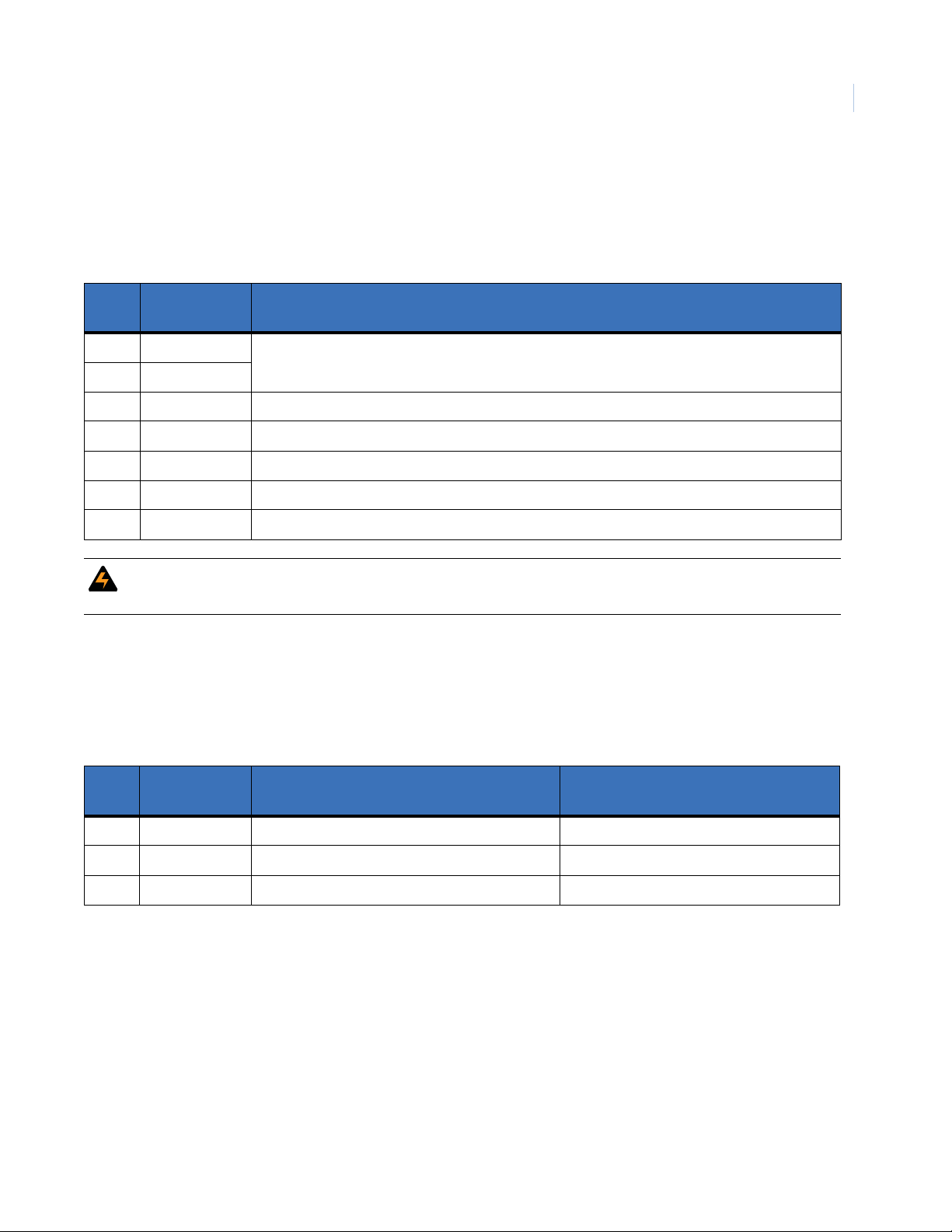
Connections for Terminal Block 10 (ACURT2 and ACURT4)
Power Connections
Table 12. Terminal Block TB10 Pin Number Identification
Pin No. Term. Strip ID Description
1 24 VAC INPUT 24 VAC Input 40 Volt Amps
2 24 VAC INPUT
3 Frame Ground Frame Ground (connected to cabinet stud)
4 0 V Ground
5 0 V Ground
6 Battery 24 V+ UPS Batteries Positive
7 Battery 24 V- UPS Batteries Negative
(from plug in transformer)
Installing the ACURT Panel
Chapter 2
33
WARNING: The ACURT board requires 24 AC power. The plug in AC power supply can only be use to power one
ACURT board.
Connections for Terminal Block 11 (ACURT2 and ACURT4)
Cabinet Tamper Connections
Table 13. Terminal Block TB11 Pin Number Identification
Maximum Distance
Pin No. Term. Strip ID Description
1ACPFAC Power Fault Input 24 Gauge
2 0 V Power Fault & Tamper Input Common Not Applicable – Factory Wired
3 CTSW Cabinet Tamper Switch 24 Gauge
Belden or Equivalent Cable No.
Page 50

TOPAZ ACURT2 & ACURT4
34
Hardware Installation Guide
Connections for Terminal Block 12, 13, and 14 (ACURT4 Only)
Reader 2 Connections
Table 14. Terminal Block TB12, 13, and 14, Pin Number Identification
Term.
TB# Pin#
12 1 +12 VDC Fused 12 VDC Output 9514-22 AWG
12 2 +5 VDC Fused 5 VDC Output
12 3 0 V 0 Volts
12 4 DATA 0 Reader Data 0 (Green)
12 5 DATA 1 Reader Data 1 (White)
12 6 RED LED Red LED
12 7 GREEN LED Green LED
12 8 BUZZER Buzzer
13 1 Z0+ Normally Closed
13 2 Z0-
13 3 Z1+ Normally Open
13 4 Z1-
13 5 Z2+ Normally Closed
13 6 Z2-
Strip ID Description
Door Contact
Request To Exit Contact
Spare Input
9407-22 AWG at 1000 feet (305 meters)
9409-18 AWG at 4000 feet (1220 meters)
9407-22 AWG at 1000 feet (305 meters)
9409-18 AWG at 4000 feet (1220 meters)
9407-22 AWG at 1000 feet (305 meters)
9409-18 AWG at 4000 feet (1220 meters)
Maximum Distance
Belden or Equivalent Cable No.
14 1 NC Door Strike Relay Normally Closed 9409-18 AWG See WARNING
14 2 C Door Strike Relay Common
14 3 NO Door Strike Relay Normally Open
Page 51

Connections for Terminal Block 15, 16, and 17 (ACURT4 Only)
Reader 3 Connections
Table 15. Terminal Block TB15, 16, and 17, Pin Number Identification
TB# Pin# Term. Strip ID Description
15 1 +12 VDC Fused 12 VDC Output 9514-22 AWG
15 2 +5 VDC Fused 5 VDC Output
15 3 0V 0 Volts
15 4 DATA 0 Reader Data 0 (Green)
15 5 DATA 1 Reader Data 1 (White)
15 6 RED LED Red LED
15 7 GREEN LED Green LED
Belden or Equivalent Cable No.
Installing the ACURT Panel
Maximum Distance
Chapter 2
35
15 8 BUZZER Buzzer
16 1 Z0+ Normally Closed
16 2 Z0-
16 3 Z1+ Normally Open
16 4 Z1-
16 5 Z2+ Normally Closed
16 6 Z2-
17 1 NC Door Strike Relay Normally Closed 9409-18 AWG See WARNING
17 2 C Door Strike Relay Common
17 3 NO Door Strike Relay Normally Open
Door Contact
Request-to-Exit Contact
Spare Input
9407-22 AWG at 1000 feet (305 meters)
9409-18 AWG at 4000 feet (1220 meters)
9407-22 AWG at 1000 feet (305 meters)
9409-18 AWG at 4000 feet (1220 meters)
9407-22 AWG at 1000 feet (305 meters)
9409-18 AWG at 4000 feet (1220 meters)
Page 52

TOPAZ ACURT2 & ACURT4
36
Hardware Installation Guide
Connections for Terminal Block 18 (ACURT4 Only)
Reader 2 and 3 Auxiliary Relay Connections (ACURT4 Only)
Table 16. Terminal Block TB18 Pin Number Identification
Pin No. Term. Strip ID Description
1 NC Reader 0 Aux Relay Normally Closed 9409-18 AWG See WARNING
2 C Reader 0 Aux Relay Common
3 NO Reader 0 Aux Relay Normally Open
4 NC Reader 1 Aux Relay Normally Closed 9409-18 AWG See WARNING
5 C Reader 1 Aux Relay Common
6 NO Reader 1 Aux Relay Normally Open
Maximum Distance
Belden or Equivalent Cable No.
Relay Numbering for ACURT2 and ACURT4
Relay Numbers for Readers
Table 17. Relay Numbers for ACURT2 and ACURT4 Readers
Reader Number ACURT2 Relay Number ACURT4 Relay Number
Reader 0 Door Strike Relay
Reader 0 Aux Relay
Reader 1 Door Strike Relay
Reader 1 Aux Relay
Reader 2 Door Strike Relay
Reader 2 Aux Relay
Reader 3 Door Strike Relay
Reader 3 Aux Relay
Relay Numbers for RIM Remote Input Module
Table 18. Relay Numbers for RIM Remote Input Module
Relay
Numbers
Expansion Port
Address 4
Expansion Port
Address 5
16
17
18
19
Not Available
Not Available
Expansion Port
Address 6
16
17
18
19
20
21
22
23
Expansion Port
Address 7
K1 32 34 36 38
K2 33 35 37 39
Page 53

Relay Numbers for RRM Remote Relay Module
Table 19. Relay 128 Numbers for RRM Remote Relay Module
Installing the ACURT Panel
Chapter 2
37
Relay
Numbers
Expansion Port
Address 4
Expansion Port
Address 5
Expansion Port
Address 6
Expansion Port
K1 112 128 144 160
K2 113 129 145 161
K3 114 130 146 162
K4 115 131 147 163
K5 116 132 148 164
K6 117 133 149 165
K7 118 134 150 166
K8 119 135 151 167
K9 120 136 152 168
K10 121 137 153 169
K11 122 138 154 170
K12 123 139 155 171
K13 124 140 156 172
K14 125 141 157 173
Address 7
K15 126 142 158 174
K16 127 143 159 175
Alarm Numbering for ACURT2 and ACURT4
Alarm Numbers for Readers
Table 20. Physical to Logical Zone Numbering
Relays Physical Alarm Zones Logical Alarm Zones
Reader
Number
Strike AUX Zone 0 D.C.2Zone 1 REX2Zone 2 SPARE Lock Monitor
0 16 17 16 17 18 48 646566 67
1 18 19 20 21 22 50 686970 71
3
2
3
3
1. Lock monitor/Bond sensor: if used must be connected to Z2
2. FO=Forced Open, HO=Held Open, RT=Reader Enclosure Tamper, OFFL=Reader Off Line, DC=Door Contact , REX=Request to Exit.
3. Readers 2 and 3 are only available on the ACURT4
20 21 24 25 26 52 72 73 74 75
22 23 28 29 30 54 76 77 78 79
1
2
F.O.
H.O.2R.T.2OFFL
2
Page 54

TOPAZ ACURT2 & ACURT4
38
Hardware Installation Guide
Alarm Numbers for RIM Remote Input Module
Table 21. RIM Alarm Numbers for GE Security’s TOPAZ
Expansion Port
Zone Input
IN1 128 144 160 176
IN2 129 145 161 177
IN3 130 146 162 178
IN4 131 147 163 179
IN5 132 148 164 180
IN6 133 149 165 181
IN7 134 150 166 182
IN8 135 151 167 183
IN9 136 152 168 184
IN10 137 153 169 185
IN11 138 154 170 186
IN12 139 155 171 187
IN13 140 156 172 188
IN14 141 157 173 189
Address 4
Expansion Port
Address 5
Expansion Port
Address 6
Expansion Port
Address 7
IN15 142 158 174 190
IN16 143 159 175 191
IN17 96 100 104 108
IN18 97 101 105 109
IN19 98 102 106 110
RIM
Off-line
99 103 107 111
Alarm Numbers for RRM Remote Relay Module
Table 22. RRM Alarm Numbers
Expansion Port
Zone Number
I1 97 101 105 109
I2 98 102 106 110
RRM Off-line 99 103 107 111
Address 4
Expansion Port
Address 5
Expansion Port
Address 6
Expansion Port
Address 7
Page 55

Installing the ACURT Panel
Connections for IFS fiber communication
Host PC to ACURT Panel (Model D1010 RS232/RS422 only)
Table 23. Host PC to/from D1010 Transciever connections
From Host PC to D1010 Transciever D1010 to D1010 From D1010 Transciever to ACURT Panel
Chapter 2
39
DB9 Connector PINs D1010 Transciever Pins XTMR to REC
3 3 (RS232 Out) 7 (+ DATA IN) TB1-8 (RX+)
2 7 (+ DATA IN) 6 (- DATA IN) TB1-9 (RX-)
5 8 (|||----) 5 (+ DATA OUT) TB1-6 (TX+)
REC to XTMR
D1010 Transciever Pins ACURT Connections
4 (- DATA OUT) TB1-7 (TX-)
Multi-drop ACURT Panel to ACURT Panel (Model D1315 4 Wire RS485 only)
Table 24. Multi-drop ACURT to/from D1315 Fiber Converter connections
ACURT to D1315 Fiber Converter D1315 to D1315 D1315 Fiber Converter to ACURT
ACURT Connections D1315 Connections DATA REC to DATA XTMR
TB1-8 (RX+) PIN 4 (D-4) PIN 4 (D-4) TB1-8 (RX+)
TB1-9 (RX-) PIN 6 (D-6) PIN 6 (D-6) TB1-9 (RX-)
TB1-6 (TX+) PIN 1 (D-1) PIN 1 (D-1) TB1-6 (TX+)
TB1-7 (TX-) PIN 3 (D-3) PIN 3 (D-3) TB1-7 (TX-)
DATA XTMR to DATA REC
D1315 Connections ACURT Connections
ACURT Panel to RIM or RRM (Model D1315 4 Wire RS485 only)
Table 25. RIM/RRM to/from D1315 Fiber Converter connections
ACURT to D1315 Fiber Converter D1315 to D1315 D1315 Fiber Converter to ACURT
ACURT Connections D1315 Connections DATA REC to DATA XTMR
TB8-4 (RX+) PIN 4 (D-4) PIN 4 (D-4) (TX+)
TB8-5 (RX-) PIN 6 (D-6) PIN 6 (D-6) (TX-)
TB8-2 (TX+) PIN 1 (D-1) PIN 1 (D-1) (RX+)
TB8-3 (TX-) PIN 3 (D-3) PIN 3 (D-3) (RX-)
DATA XTMR to DATA REC
D1315 Connections RIM/RRM Connections
Page 56

TOPAZ ACURT2 & ACURT4
40
Hardware Installation Guide
Wiring the Host Communications
Bandwidth requirements
The tables below provide the typical bandwidth requirements for the Topaz file server and workstations.
Table 26. Communication Bandwidth Reference)
Description Equation Max Bandwidth
9,600 BPS - PPP
14,400 BPS - PPP
28,800 BPS - PPP
57,600 BPS - PPP
Ethernet
Table 27. General Data: Packet size
Description Minimum Maximum
Server to Workstation Polling - 10 Sec = 10 Bytes 10 Bytes
Server to Server Polling - 10 Sec = 10 Bytes 10 Bytes
Card Record (depends on number of fields used) = 2 KBytes 13.5 Kbytes
Alarm Condition Transaction = 2 Kbytes 2 Kbytes
9,600 BPS x 60 sec
28,800 BPS x 60 sec
14,400 BPS x 60 sec
57,600 BPS x 60 sec
10,000,000 BPS x 60 sec
÷ 8 Bits =
÷ 8 Bits =
÷ 8 Bits =
÷ 8 Bits =
÷ 8 Bits =
72 KB per minute
108 KB per minute
216 KB per minute
432 KB per minute
7500 KB per minute
Connecting RS-232C Interface to ACURT2 and ACURT4 Controllers
The RS-232 interface i s a si mple communi cati ons int erface used be tween co mpute rs or modems and ACURT2
or ACURT4 controllers. The maximum overall length of the wires from the host computer to the ACURT2 or
ACURT4 controller is 50 feet (15 meters). Only one device per RS-232 path is supported.
Provide a shielded cable (three wires and shield) from the host computer’s serial port to the ACURT2 or
ACURT4 controller. Tables 28 and12 29 show the cable connections. The shield attaches to chassis ground.
Table 28. PC (9-pin) to ACURT2 or ACURT4 (RS-232)
DB-9 DTE Pin Numbers ACURT2 and ACURT4 Controller Description
2TXD (TB1-2) Transmit Data
3 RXD (TB1-3) Receive Data
5 SIG GND (TB1-1) Signal Ground
Page 57
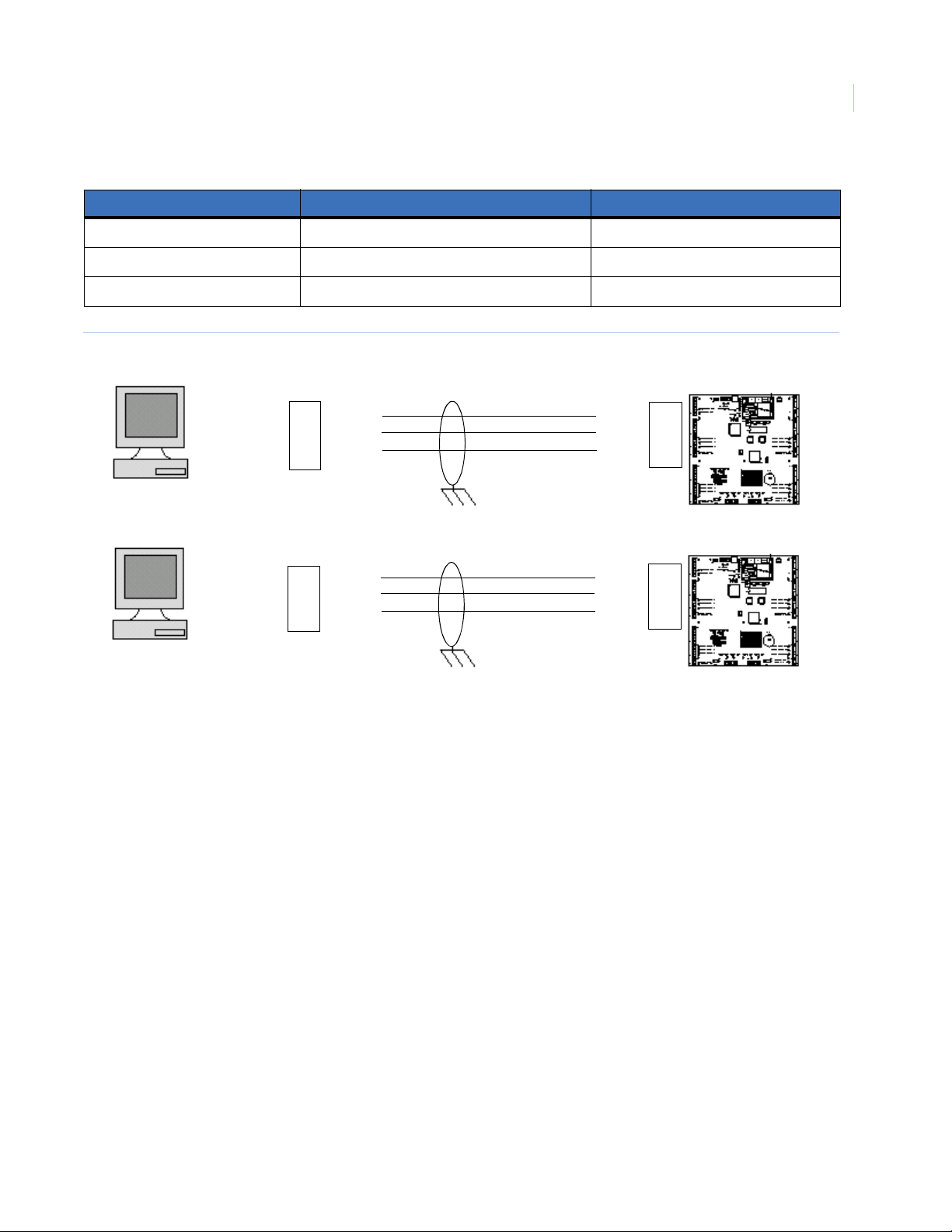
Table 29. PC (25-pin) to ACURT2 and ACURT4 (RS-232)
DB-25 DTE Pin Numbers ACURT2 and ACURT4 Controller Description
2 RXD (TB1-3) Receive Data
3 TXD (TB1-2) Transmit Data
7 SIG GND (TB1-1) Signal Ground
Figure 12. Typical RS-232C Interface Wiring from PC to ACURT2 or ACURT4 Controller
Installing the ACURT Panel
Chapter 2
41
RXD
TXD
SIG
GND
TB1
3
2
1
RS-232 PC
Comm.
Port
9-Pin
3
2
5
TX
RX
GND
ACURT2
ACURT4
RXD
TXD
SIG
GND
TB1
3
2
1
RS-232 PC
Comm.
Port
25-Pin
2
3
7
TX
RX
GND
ACURT2
ACURT4
Connecting RS-485 Converter to the ACURT2 or ACURT4
Provide a two-pair shielded cable (Belden 9842 or equivalent required) between the server’s communication
port to the ACURT2 or ACURT4 controller.
RS-485 communications must be used if the server is more than 50 feet (15 meters) from an ACURT
controller, or if there are multiple controllers.
Use the supplied RS-232C-to-RS-485 converter with the six-foot DB9 to DB25 cable to make this connection.
Page 58

TOPAZ ACURT2 & ACURT4
42
Hardware Installation Guide
Installing the NCIC-5 RS-485 Converter
Configure the ACURT2 or ACURT4 controller for RS-485 communication and wire the units as shown in
Figure 4. An RS-485 terminator must be installed at the RS-485 (NCIC-5) converter as well as the farthest
ACURT2 or ACURT4 device on the communi ca ti on l ine. The maximum overall length of this ca bl e (f rom RS485 converter to the last ACURT2 or ACURT4 controller) is 4000 feet (1220 meters) using Belden 9842 or
equivalent cable. Beyond this distance a modem must be used. For Dial up to the ACU panels, a Robotics
Sportster external modem must be used at the host computer.
Table 30. Model NCIC-5 RS-485 Converter to ACURT2 or ACURT4
RS-485 Converter RS-485 Terminator ACURT2 and ACURT4 Controller Description
FR. GND Shield
RD(B) RD+ TX+ (TB1-6) Transmit Data (+)
RD(A) RD2 TX- (TB1-7) Transmit Data (-)
TD(B) TD+ RX+ (TB1-8) Receive Data (+)
TD(A) TD2 RX- (TB1-9) Receive Data (-)
+12VDC +12 Volt
GND SIG GND (TB1-1) Power Supply Common
Jumpers on NCIC-5
Echo = ON
Control = No Jumper
Figure 13. RS485 Communication wiring for Multiple ACURTs with NCIC-5 RS485 Converter
Connect
Plug-in Transformer
12V and Ground
Terminate
Screw terminal
to earth ground
TD(B)
TD(A)
RD(B)
RD(A)
NCIC-5
RS485
Converter
12V
G
T+
TR+
R-
T+
TR+
R-
RS485
Terminator
124824
SW1
1234
SW1
1234
G G G
T+
T-
R+
R-
TB1 TB1 TB1
ACURT
SW4 = 0
T+
TR+
R-
ACURT
SW4 = 1
SW2 - Set to 9600 Baud - Dip Switches 1,2,3 On (All ACURTs)
SW3 - All ACURTs set Dip Switch 7 On
SW1
1234
T+
TR+
R-
ACURT
SW4 = 2
Last ACURT
Page 59

NCIC Jumper Settings: Echo = On, Control = No Jumper
Figure 14. RS485 wiring for the ACURTs with NCIC-5 RS-485 converter in the middle of the loop
Installing the ACURT Panel
Chapter 2
43
SW1
1234
Connect
12V
Terminate
Screw terminal
to earth ground
Note: When the NCIC-5 is located in the middle of the loop, ACURTs on both ends of the loop must be
terminated.
Note: Shield refers to the over all braided shield, GND refers to the shield drain wire. Transmit should use one twisted pair and
receive should use the other twisted pair.
G
T+
TR+
R-
TB1
ACURT
Address 0
Plug-in Transformer
12V and Ground
TD(B)
TD(A)
RD(B)
RD(A)
NCIC-5
RS485
Converter
G
T+
TR+
R-
SW1
1234
G
T+
TR+
R-
TB1
ACURT
Address 1
Wiring a NCIC-5 RS-485 Converter to the Server
If you do not have the 6-foot cable covered above you may wire the RS-485 converter as shown below
Table 31. Connecting DB-9 RS-485 Converter
DB-9 Pin Numbers Male RS-485 Converter NCIC-5 25-Pin Female
23
32
57
The model NCIC-5 RS-485 converter can be plugged into the communication port via the supplied DB9 to
DB25 six-foot cable.
Page 60

TOPAZ ACURT2 & ACURT4
44
Hardware Installation Guide
Multi-dropping RS-485 from a LAN Connected ACURT
You may still multi-drop any ACURT panel from an ACURT connected to the LAN via RS-485 up to a
maximum of 4,000 feet to the last ACURT from the LAN connected ACURT. See the wiring diagram below
and the wiring table that follows.
Figure 15. Multi-Drop RS-485 Wiring from a LAN Connected ACURT.
ACURT
Address 15
1 Sig GND
6 TX+
7 TX 8 RX+
9 RX -
Up to 15 panels may
be added to the loop
1 Sig GND
6 TX+
7 TX 8 RX+
9 RX -
ACURT
Address 1
1 Sig GND
6 TX+
7 TX 8 RX+
9 RX -
ACURT
Address 0
1 Sig GND
6 TX+
7 TX 8 RX+
9 RX -
LAN / WAN
Connection
Last panel in loop
must be terminated
Notes:
4,000 feet maximum
• SW3 DIP switch 1 must be ON to enable the LAN connection.
• Use SW1 to terminate the last ACURT panel in the RS484 loop.
DIP Switch Settings for ACURT2 and ACURT4
The locations of the various DIP switches on the ACURT2 and ACURT4 are shown in Figure 11. Tables 32
through 38 describe how each DIP switch (SW1- SW7) is set. The rotary switch (SW4) described in Table 35
provides sixteen addresses 0 to 15 (0 to 'F' hexadecimal) for ACURT addressing.
Note: Switches SW2, SW3 and SW4 are read only at power-up and are ignored thereafter. When switch settings are changed,
power MUST be turned OFF then turned ON AFTER the settings are changed. You can use SW7 to cycle power on the
board.
DIP switch SW1 Communication Port Termination
To be switched on to terminate communications line when panel is last on the RS-485 loop.
Table 32. Switch SW1 Settings on the ACURT2 and ACURT4
Switch SW1 Description
S1 ON = Host TX Line Terminated
S2 ON = Host RX Line Terminated
S3 ON = Expansion Module Port TX Line Terminated
S4 ON = Expansion Module Port RX Line Terminated
Page 61

Installing the ACURT Panel
DIP Switch SW2 Settings Baud Rate, Dial-up, Parity, and Com Type
Table 33. DIP Switch SW2 Settings on the ACURT2 and ACURT4 Controller
Switch SW2 Switch Setting Function
S1 S2 S3 Host Communication Baud Rate
OFF OFF OFF 19200
S1 ON OFF OFF 38400
OFF ON OFF 57600
through ON ON OFF 1200
OFF OFF ON 115200
S3 ON OFF ON 2400
OFF ON ON 4800
1
ON
S4 OFF
ON
1
1
ON
1
9600
DES Encryption Enabled
Chapter 2
45
S5 ON Dial-Up Host Communications
S6 ON Use 5-wire RS-232 using RTS & CTS
S7 OFF
S8 ON Host Communication uses No Parity (modem)
1. Denotes default setting
OFF
OFF
OFF
1
1
1
1
Dedicated Host Communications
Use RS-485 or 3-wire RS-232
Spare - Set OFF
Host Communication uses Even Parity
Page 62

TOPAZ ACURT2 & ACURT4
46
Hardware Installation Guide
DIP Switch SW3 Settings
Table 34. DIP Switch SW3 Settings on the ACURT2 and ACURT4 Controller
Switch SW3 Description
S1 ON = LAN Enabled
S2 ON = Allow LAN IP Parameters Update
S3 ON = Default LAN IP Parameter
S4 ON = Triple DES Encryption Enabled
S5 ON = Spare – Leave OFF
S6 ON = Magnetic Stripe Cards
S7 ON = Battery Backed Up RAM
S8 ON = Disable Watch Dog Timer
1. Denotes default setting
1
Dip Switch SW4 (rotary switch) Settings ACURT Panel Addressing
Table 35. Rotary Switch SW4 Settings on the ACURT2 and ACURT4
Switch SW4 Description
0 ACURT field Panel # 0
1 ACURT field Panel # 1
2 ACURT field Panel # 2
3 ACURT field Panel # 3
4 ACURT field Panel # 4
5 ACURT field Panel # 5
6 ACURT field Panel # 6
7 ACURT field Panel # 7
8 ACURT field Panel # 8
9 ACURT field Panel # 9
A ACURT field Panel # 10
B ACURT field Panel # 11
C ACURT field Panel # 12
D ACURT field Panel # 13
E ACURT field Panel # 14
F ACURT field Panel # 15
Page 63

Installing the ACURT Panel
DIP Switch SW5 and SW6 Settings Alarm Zone Termination for Readers
Table 36. DIP Switch SW6 settings alarm termination for readers
ON Position = Terminated – No Input Device Present
Switch SW5
S1 Terminates Zone Input Reader 0 Zone 0 with a 1k-ohm resistor
S2 Terminates Zone Input Reader 0 Zone 1 with a 1k-ohm resistor *
S3 Terminates Zone Input Reader 0 Zone 2 with a 1k-ohm resistor
S4 Terminates Zone Input Reader 1 Zone 0 with a 1k-ohm resistor
S5 Terminates Zone Input Reader 1 Zone 1 with a 1k-ohm resistor *
S6 Terminates Zone Input Reader 1 Zone 2 with a 1k-ohm resistor
Table 37. DIP Switch SW6 settings alarm termination for readers
Switch SW6
OFF Position = Not Terminated – Zone In Use With End Of Line Resistor
Chapter 2
47
S1 Terminates Zone Input Reader 2 Zone 0 with a 1k-ohm resistor
S2 Terminates Zone Input Reader 2 Zone 1 with a 1k-ohm resistor
1
S3 Terminates Zone Input Reader 2 Zone 2 with a 1k-ohm resistor
S4 Terminates Zone Input Reader 3 Zone 0 with a 1k-ohm resistor
S5 Terminates Zone Input Reader 3 Zone 1 with a 1k-ohm resistor
1
S6 Terminates Zone Input Reader 3 Zone 2 with a 1k-ohm resistor
1. If exit push button is not connected, (reader zone 1) another 1000 ohm resistor must be installed across the zone input
DIP Switch SW7 Power Switch
Table 38. Switch SW7 Power Switch on the ACURT2 and ACURT4
Switch SW7 Description
Slide Switch Turns on Boards Power Supply
Page 64

TOPAZ ACURT2 & ACURT4
48
Hardware Installation Guide
Status LEDs on the ACURT2 and ACURT4
ACU Power-Up Self-test
The ACURT2 and ACURT4 should always be tested after installing any module. The power-up self-test
indicators are for both the ACURT2 and ACURT4 controller. The LEDs will light as follows: at power-up, all
ON, at hardware reset, all OFF.
Table 39. Power-Up LED Status
Status LED Description
1 ON indicating power-up
2 ON indicating successful RAM test
3 ON indicating successful PROM test
4 ON indicating initialization complete (1 second)
ACURT Online Status
The normal operating indicators for the ACURT Controllers are indicated by LEDs 1 – 4. The LEDs on the
ACURT Controller’s PCB will light as follows:
Table 40. ACURT Online Status LEDS
Status LED Description
1Flashes at a 1 Hz rate
2 ON while transmitting to the Remote Modules
3
4 ON if zone voltage reference is ever out of range (indicates board or power supply failure)
Two seconds OFF, then blinks once if Reader 0 is online, followed by blinking twice if Reader 1 is online,
etc.
LAN LED Status
Table 41. LAN LED Status
Status LED Description
TX ON Transmitting
RX ON Receiving
COL ON Collision
Link ON Cable connected
Rev ON Cable reversed
Page 65

Host Port LED Status
Table 42. Host Port LED Status
Status LED Description
Transmit Data ON transmitting data to host computer
Receive Data ON Receiving data from host computer
Reader Zones LED Status
Table 43. Reader Zone LED Status
Status LED Description
OFF - Secure
Reader 0-3
Zone 0,1, & 2
ON - Active Alarm
Fast Flashing - Trouble (open or short, etc.)
Slow Flashing- Masked
Installing the ACURT Panel
Chapter 2
49
Relay and Door Strike LED Status
Table 44. Relay and Door Strike LED Status
Status LED Description
All Relays ON Relay is energized
Defaulting the Memory on the ACURT2 and ACURT4
To clear memory, first power off the ACURT2 and ACURT4. Set the even switches (positions 2, 4, 6, & 8) on
DIP switch SW2 to ON and the odd switches (positions 1, 3, 5, & 7) to OFF. Set the polling address of the
Rotary Switch SW4 to F. Apply power to the ACURT2 or ACURT4. LEDs 1-4 will blink together indicating
that the operation is complete. Turn power off and reset switches SW2 and SW4 to the desired settings.
Page 66

TOPAZ ACURT2 & ACURT4
50
Hardware Installation Guide
Page 67

Chapter 3 Reader Installation
This chapter provide in depth information about how readers are installed and
wired to the TOPAZ ACURT2 and ACURT4 Panels. This includes:
Overview of Reader Installation. . . . . . . . . . . . . . . . . . . . . . . . . . . . . . . 52
Reader Installation Direct Connection. . . . . . . . . . . . . . . . . . . . . . . . . . 53
Page 68

TOPAZ ACURT2 & ACURT4
52
Hardware Installation Guide
Overview of Reader Installation
GE Security’s TOPAZ system comes standard with either one set of two (2), or one set of four (4) of the
following standard readers.
Standard Readers :
• HID ProxPoint Plus 6005
• HID MiniProx 5365
Optional Readers and Keypads:
• HID ProxPro (with Keypad) 5355
• HID MaxiProx 5375 Long Range
• GE Security K11L Keypad
• GE Security Transition Reader Series
This section covers the installation and wiring for the standard and optional readers/keypads for the GE
Security TOPAZ system.
If the reader you are installing is not covere d i n t his manual or you need additional i nf ormation, please refer to
the documentation that was shipped with the reader.
Refer to tables 8, 9, and 11 for reader 0 and 1 connections and tables 14 through 16 for readers 2 and 3
connections, available only on the ACURT4 controller.
Page 69
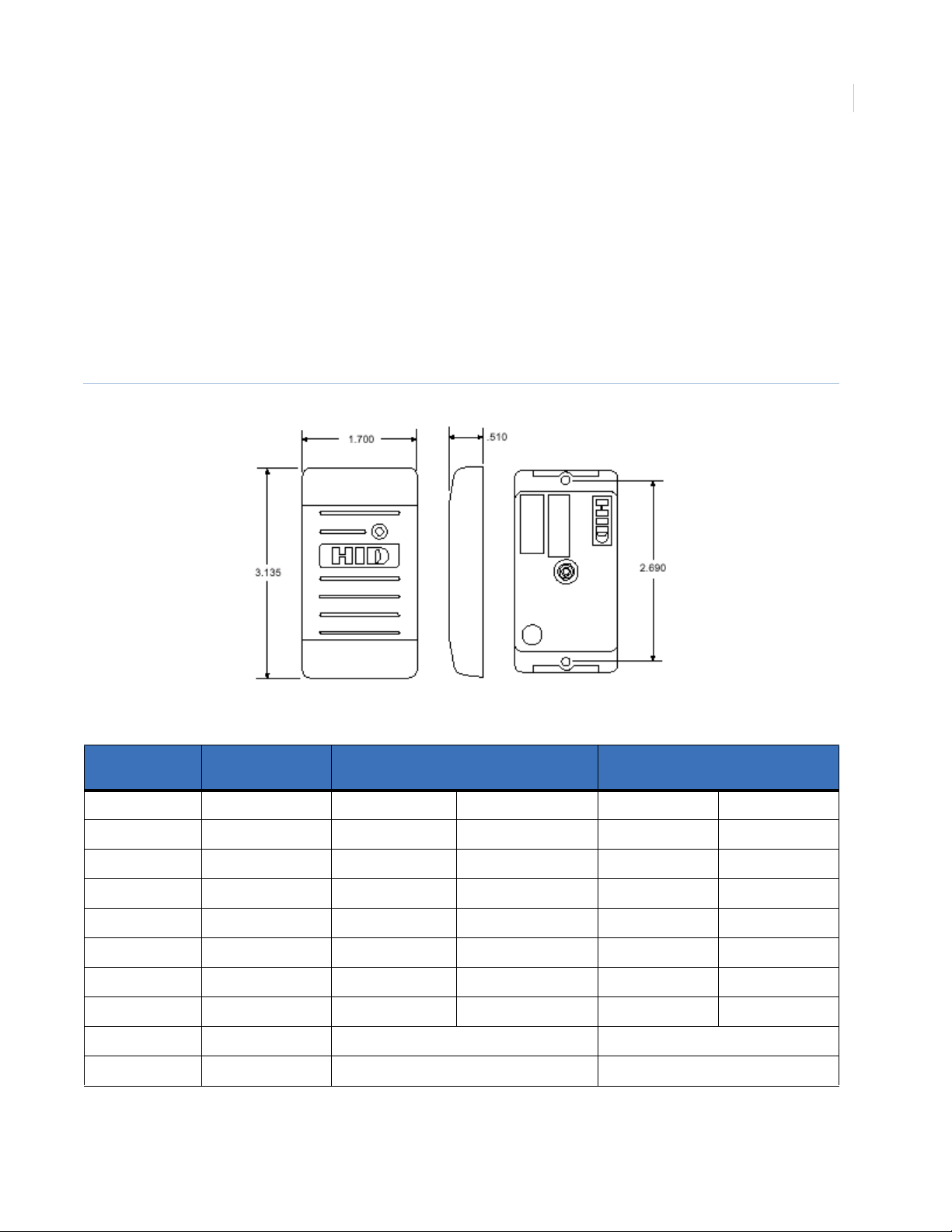
Reader Installation
Reader Installation Direct Connection
The following readers can only be connected to the ACURT Reader Ports.
See the installation sheets packaged with the reader for specifications and other reader information.
Wiring HID ProxPoint Plus 6005
Refer to tables , , and 11 for reader 0 and 1 connections and tables 14 through 16 for readers 2 and 3
connections, available only on the ACURT4 controller.
Figure 16. HID ProxPoint Plus 6005
Chapter 3
53
Table 45. Wiring HID ProxPoint Reader to the ACURT
Reader
Wire Color
Red +12 Volts Pin 1 +12 VDC Pin 1 +12 VDC
Black Ground Pin 3 0V Pin 3 0V
Green Data 0 Pin 4 Data 0 Pin 4 Data 0
White Data 1 Pin 5 Data 1 Pin 5 Data 1
Shield Shield Ground Pin 3 0V Pin 3 0V
Orange Green LED Pin 7 Green LED Pin 7 Green LED
Brown Red LED Pin 6 Red LED Pin 6 Red LED
Yellow Beeper Pin 8 Buzzer Pin 8 Buzzer
Blue Data Hold No Connection No Connection
Violet Card Present No Connection No Connection
Description
Connection to ACURT2 TB2 or TB5
Reader 0 or Reader 1
Connection to ACURT4 TB12 or TB15
Reader 2 or Reader 3
The reader can be installed up to a maximum cable distance of 500 feet (152 meters) from the ACURT2 or
ACURT4 using Belden cable #9514 or equivalent (4 pairs) 22 AWG, over-all foil shield.
Page 70
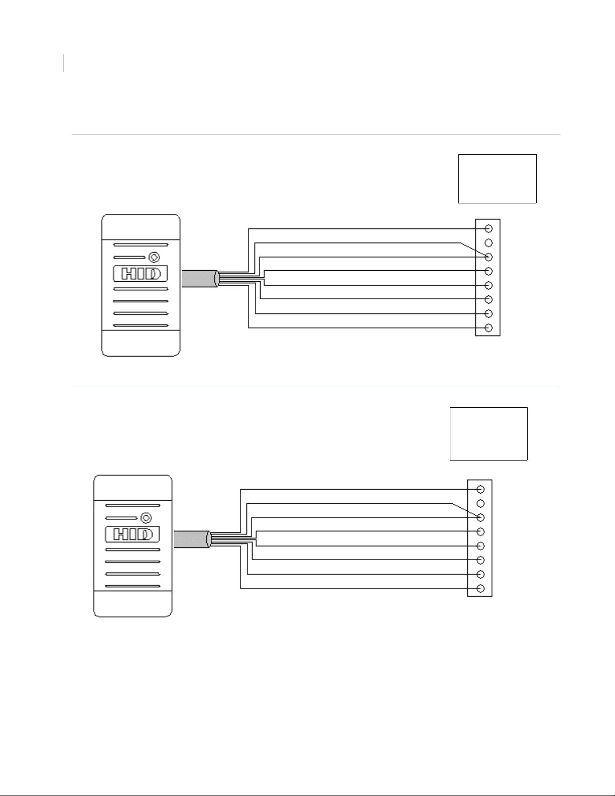
TOPAZ ACURT2 & ACURT4
54
Hardware Installation Guide
HID ProxPoint Plus 6005 Point to Point Wiring
Figure 17. HID ProxPoint Plus 6005 Point to Point Wiring (ACURT2 and 4)
ACURT2 & 4
TB2 Reader 0
TB5 Reader 1
Figure 18. HID ProxPoint Plus 6005 Point to Point Wiring - ACURT4 Only
Red - +12 VDC
Black - Ground
Shield - Ground
Green - Data 0
White - Data 1
Brown - Red LED
Orange - Green LED
Yellow - Beeper
Red - +12 VDC
Black - Ground
Shield - Ground
Green - Data 0
White - Data 1
Brown - Red LED
Orange - Green LED
Yellow - Beeper
Pin 1
Pin 2
Pin 3
Pin 4
Pin 5
Pin 6
Pin 7
Pin 8
ACURT4
Readers 2 & 3
TB12 & TB15
Pin 1
Pin 2
Pin 3
Pin 4
Pin 5
Pin 6
Pin 7
Pin 8
Page 71
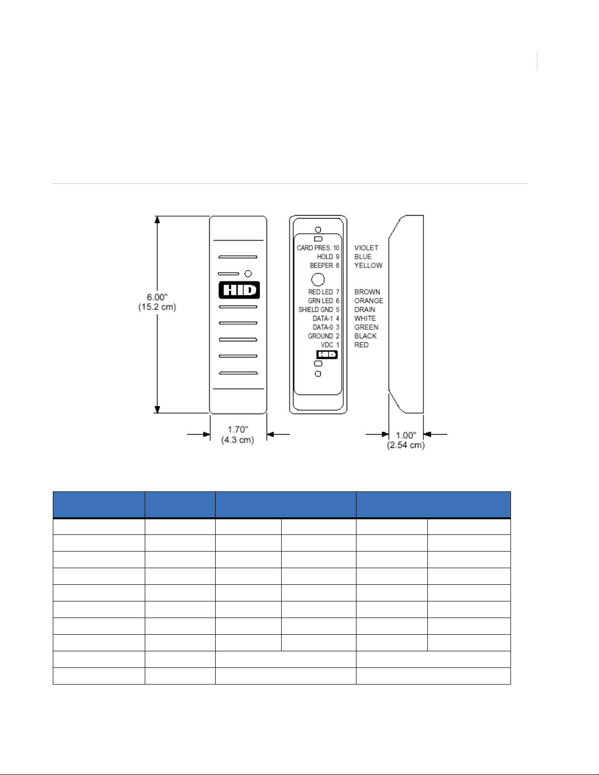
Reader Installation
Wiring HID MiniProx Model 5365 Reader
See the installation sheets packaged with the reader for specifications and other reader information.
Refer to tables 8, 9 and 11 for reader 0 and 1 connections and tables 14 through 16 for readers 2 and 3
connections, only available on the ACURT4 controller.
Figure 19. HID MiniProx 5365
Chapter 3
55
Table 46. Wiring HID MiniProx Model 5365 Reader to the ACURT
Reader
Wire Color
Red +12 Volts Pin 1 +12 VDC Pin 1 +12 VDC
Black Ground Pin 3 0V Pin 3 0V
Green Data 0 Pin 4 Data 0 Pin 4 Data 0
White Data 1 Pin 5 Data 1 Pin 5 Data 1
Shield Shield Gnd Pin 3 Ground Pin 3 Ground
Orange Green LED Pin 7 Green LED Pin 7 Green LED
Brown Red LED Pin 6 Red LED Pin 6 Red LED
Yellow Beeper Pin 8 Buzzer Pin 8 Buzzer
Blue Data Hold No Connection No Connection
Violet Card Present No Connection No Connection
Description
Connection to ACURT2 TB2 or TB5
Reader 0 or Reader 1
Connection to ACURT4 TB12 or TB15
Reader 2 or Reader 3
The reader can be installed up to a maximum cable distance of 500 feet (152 meters) from the ACURT2 or
ACURT4 using Belden cable #9514 or equivalent (4 pairs) 22 AWG, over-all foil shield.
Page 72
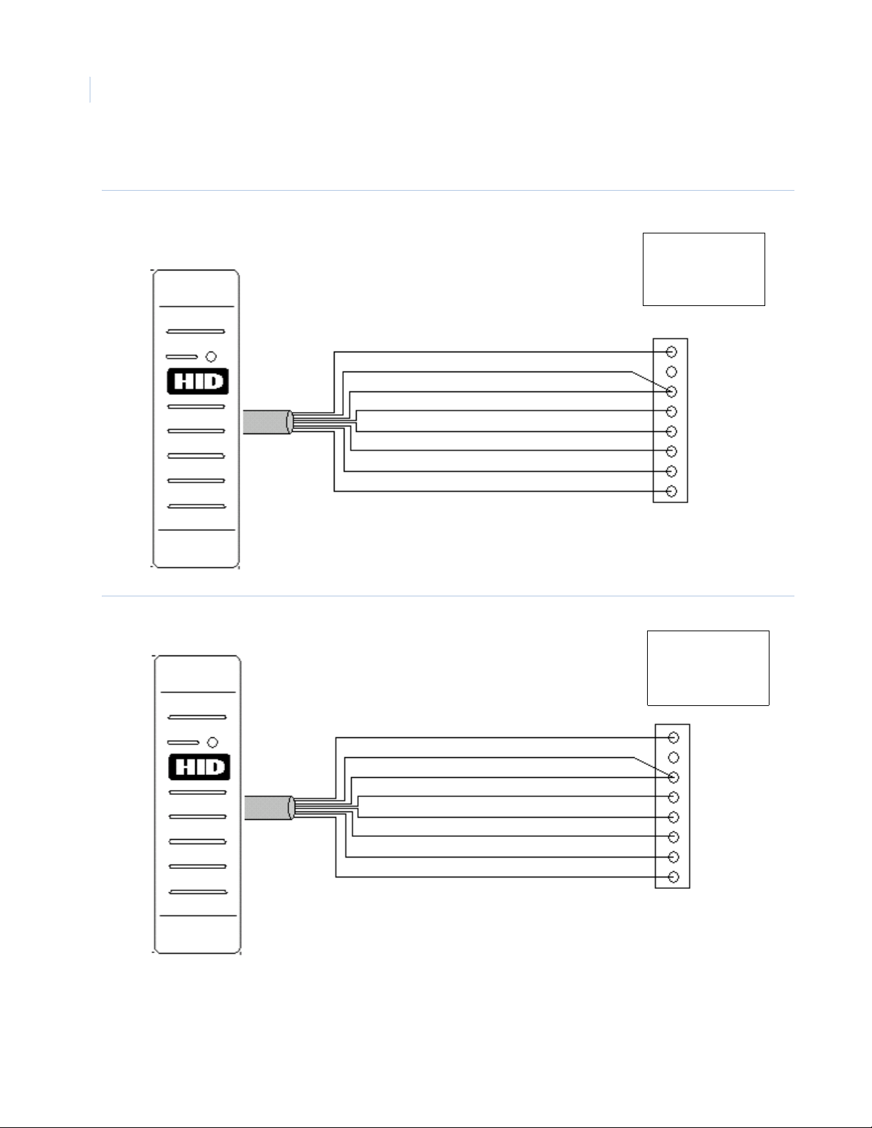
TOPAZ ACURT2 & ACURT4
56
Hardware Installation Guide
HID MiniProx Model 5365 Point to Point Wiring
Figure 20. HID MiniProx Model 5365 Point to Point Wiring (ACURT2 and 4)
ACURT2 & 4
TB2 Reader 0
TB5 Reader 1
Orange - Green LED
Figure 21. HID MiniProx Model 5365 Point to Point Wiring - ACURT4 Only
Orange - Green LED
Red - +12 VDC
Black - Ground
Shield - Ground
White - Data 1
Green - Data 0
Brown - Red LED
Yellow - Beeper
Red - +12 VDC
Black - Ground
Shield - Ground
White - Data 1
Green - Data 0
Brown - Red LED
Yellow - Beeper
Pin 1
Pin 2
Pin 3
Pin 4
Pin 5
Pin 6
Pin 7
Pin 8
ACURT4
Readers 2 & 3
TB12 & TB15
Pin 1
Pin 2
Pin 3
Pin 4
Pin 5
Pin 6
Pin 7
Pin 8
Page 73

Reader Installation
Chapter 3
Wiring Optional HID ProxPro Model 5355 Reader
See the installation sheets packaged with the reader for specifications and other reader information. Refer to
tables , , and 11 for reader 0 and 1 connections and tables 14 through 16 for readers 2 and 3 connections, only
available on the ACURT4 controller.
Figure 22. HID ProxPro 5355
57
Table 47. Wiring HID ProxPro Model 5355 Reader to the ACURT
Reader
TB1
1 +12 Volts DC Pin 1 +12 VDC Pin 1 +12 VDC
2 Ground Pin 3 0V Pin 3 0V
3 Data 0 Pin 4 Data 0 Pin 4 Data 0
4 Data 1 Pin 5 Data 1 Pin 5 Data 1
5 Return No Connection No Connection
6 Green LED Pin 7 Green LED Pin 7 Green LED
7 Red LED Pin 6 Red LED Pin 6 Red LED
8 Beeper Pin 8 Buzzer Pin 8 Buzzer
9 Hold/Card Present No Connection No Connection
10 Tamper Common No Connection No Connection
11 Tamper Select No Connection No Connection
Description
Connection to ACURT2 TB2 or TB5
Reader 0 or Reader 1
Connection to ACURT4 TB12 or TB15
Reader 2 or Reader 3
The reader can be installed up to a maximum cable distance of 500 feet (152 meters) from the ACURT2 or
ACURT4 using Belden cable #9514 or equivalent (4 pairs) 22 AWG, over-all foil shield.
Page 74

TOPAZ ACURT2 & ACURT4
58
Hardware Installation Guide
DIP Switch SW1 should be set as listed below.
Table 48. DIP Switch SW1 Settings
SW1 ON OFF Function Description
1 X Hardware Identity
2X Beeper Control
3XGreen LED Control
4 X Keypad
5 X Single/Dual LED Control
6 X Wiegand Data 1 Bias
7X
8X Not Used
P1 jumper 1 and 2 when mounted on a metallic surface other wise jumper 2 and 3.
P2 jumper should be on 2 and 3.
Page 75

Reader Installation
Wiring Optional HID MaxiProx Model 5375 Long Range Reader
See the installation sheets packaged with the reader for specifications and other reader information.
Refer to tables 8, 9, and 11 for reader 0 and 1 connections and tables 14 through 16 for readers 2 and 3
connections, only available on the ACURT4 controller.
Figure 23. HID MaxiProx 5375 Long Range Reader
Chapter 3
59
Table 49. Wiring HID MaxiProx Model 5375 Reader TB1 to the ACURT
5375 Reader
TB1
1
2
3 Ground Pin 3 Ground Pin 3 Ground
Table 50. Wiring HID MaxiProx Model 5375 Reader TB1 Tamper to the ACURT
5375 Reader
TB1
4 Tamper Pin 5 Z2 spare input Pin 5 Z2 spare input
5 Tamper Pin 6 Pin 6
Description
+24 Volts 24 VDC (2-Amp minimum)
Shield Do not
connect at reader
Description
Connection to ACURT2 TB2 or TB5
Reader 0 or Reader 1
Aux power required
Pin 3 Ground Pin 3 Ground
Connection to ACURT2 TB3 or TB6
Reader 0 or Reader 1
Connection to ACURT4 TB12 or TB15
Reader 2 or Reader 3
24 VDC (2-Amp minimum)
Aux power required
Connection to ACURT4 TB13 or TB16
Reader 2 or Reader 3
Page 76

TOPAZ ACURT2 & ACURT4
60
Hardware Installation Guide
Table 51. Wiring HID MaxiProx Model 5375 Reader TB2 to the ACURT
5375 Reader
TB 2
Description
Connection to ACURT2 TB2 or TB5
Reader 0 or Reader 1
Connection to ACURT4 TB12 or TB15
Reader 2 or Reader 3
1 Data 0 Pin 4 Data 0 Pin 4 Data 0
2 Data 1 Pin 5 Data 1 Pin 5 Data 1
4 Green LED Pin 7 Green LED Pin 7 Green LED
5 Red LED Pin 6 Red LED Pin 6 Red LED
6 Beeper Pin 8 Buzzer Pin 8 Buzzer
3, 7, 8, & 9 Not Used
Note: The reader can be installed up to a maximum cable distance of 500 feet (152 meters) from the ACURT2 or ACURT4.
Table 52. DIP Switch SW1 Factory Defaults
SW1 ON OFF Function Description
1 X Wiegand Data Mode
2 X Wiegand Data Mode
3 X Wiegand Data Mode
4 X Beep on Valid Card Read
5 X Flash Green After Valid Card Read
6 X External Dual LED control
7XNot Used
8XNot Used
Table 53. DIP Switch SW2 Settings
SW2 ON OFF Function Description
1 X Leave as shown; not used.
2X
3X
4X
5X
6 X
7X
8X
Page 77

Table 54. DIP Switch SW 5 Settings
SW 5 ON OFF Function Description
1 X Wiegand Data 0 Non-Isolated Output
2 X Wiegand Data 1 Non-Isolated Output
3 X Leave as shown; not used.
4X
5X
6X
7X
8X
Jumper Pins on 5375 Reader
Reader Installation
Chapter 3
61
Table 55. Jumper Pin settings
Pin Jumper No. Function Position Comment
P1
P2 DC Voltage No Jumper Factory default +24 VDC
P3 Interface jumpers
P4 1 & 2
Notes:
Factory default is no jumper on P2. The reader uses 24 VDC in this configuration.
Use a quality 24 VDC linear type power supply; the minimum current requirement is 2 Amperes per 5375 reader. See
page 5 of 20, #9 of the Parts List in the HID installation manual.
The ground of the reader and the ground of the power supply must be common. Do this by connecting 0V (negative) of
the linear power supply to TB2-3 or TB5-3 of the ACURT2 or TB12-3 or TB15-3 of the ACURT4.
Use of a tamper switch is optional; if one is used, it is not internal and requires a wired alarm zone.
Pins 3 and 4 jumpers are use in conjunction with the settings on SW 1 and SW 5 to provide a Wiegand format output.
See Mode Chart table below.
The HID installation manual 5375-901 that comes with the 5375 reader should be used as an additional guide.
Tamper NC 2 & 3 Closed circuit tamper; tamper use optional; must
run alarm wire to Z2
1 & 2 Used with Dip switches SW1 & SW5;
(Wiegand Format)
See mode chart below
Mode Chart
Table 56. 5375 Reader Switch Settings For Wiegand Mode
Mode SW1 - 1 SW1 - 2 SW1 - 3 SW5 - 3 SW5 - 4 SW5 - 5 P3 & P4 Jumpers
Wiegand ON ON ON NA NA NA 1 & 2
Page 78

TOPAZ ACURT2 & ACURT4
62
Hardware Installation Guide
Wiring Optional K11L Keypad
Figure 24. GE Security K11L Keypad
Refer to tables , , and 11 for reader 0 and 1 connections and tables 14 through 16 for readers 2 and 3
connections, only available on the ACURT4 controller.
The keypad can be installed up to a maximum cable distance of 500 feet (152 meters) from the ACURT2 or
ACURT4 using Belden cable #9514 or equivalent (4 pairs) 22 AWG, over-all foil shield.
Table 57. Wiring GE Security K11L Keypad to the ACURT
Connection to ACURT2 TB2 or TB5
J1 on K11L Description
Pin 1 0V Pin 3 0V Pin 3 0V
Pin 2 Data 1 Pin 5 Data 1 Pin 5 Data 1
Pin 3 Data 0 Pin 4 Data 0 Pin 4 Data 0
Pin 4 +5V Pin 2 +5 VDC Pin 2 +5 VDC
Pin 5 Green LED Pin 7 Green LED Pin 7 Green LED
Pin 6 Yellow LED No Connection No Connection
Pin 7 Red LED Pin 6 Red LED Pin 6 Red LED
Pin 8 Buzzer Pin 8 Buzzer Pin 8 Buzzer
Figure 25. Rear View of the K11 Keypad.
Reader 0 or Reader 1
J1
J2
Connection to ACURT4 TB12 or TB15
Reader 2 or Reader 3
Page 79

Reader Installation
Jumper Configuration For Reader Support
Jumpers W1 and W2 must be set to position B-C for Wiegand (typical) or A-B for magnetic stripe
Figure 26. K11L Board Only with Jumper Locations
GE Security
Jumper settings
listed on-board
Chapter 3
63
Jumpers
W1 and W2
Page 80
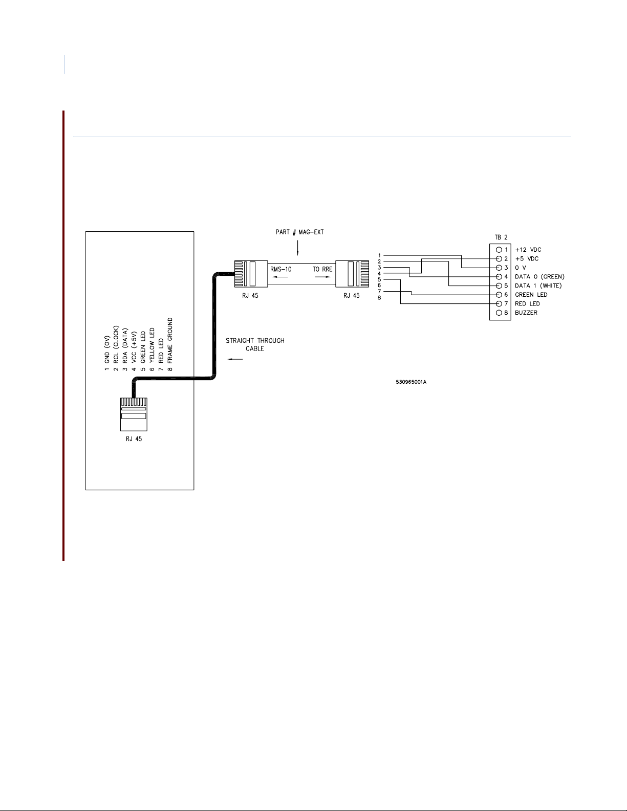
TOPAZ ACURT2 & ACURT4
64
Hardware Installation Guide
Wiring the RMS-10 to the ACURT 2/4
Figure 27. Wiring the RMS-10 to the ACURT
Page 81

Wiring Transition Series readers to the ACURT 2/4
Figure 28. Wiring Transition Series readers to the ACURT
Reader Installation
Chapter 3
65
Page 82

TOPAZ ACURT2 & ACURT4
66
Hardware Installation Guide
Page 83

Chapter 4 Remote Expansion Modules
This chapter prov ide i n depth infor mation abo ut how Remot e Expan sion Modu les
(RIMs and RRMs) are installed and wired to the TOPAZ ACURT2 and ACURT4
Panels.
This includes:
Overview . . . . . . . . . . . . . . . . . . . . . . . . . . . . . . . . . . . . . . . . . . . . . . . . . 68
Remote Input Module Circuit Board Layout. . . . . . . . . . . . . . . . . . . . . . 69
RIM Terminal Block Connector Pin Numbers . . . . . . . . . . . . . . . . . . . . 70
Setting the DIP Switches on the RIM . . . . . . . . . . . . . . . . . . . . . . . . . . . 73
Setting the Jumper on the RIM . . . . . . . . . . . . . . . . . . . . . . . . . . . . . . . . 75
Alarm Numbers for the Remote Input Module . . . . . . . . . . . . . . . . . . . . 76
Relay Numbers for RIM Remote Input Module . . . . . . . . . . . . . . . . . . . 76
Field Testing The RIM . . . . . . . . . . . . . . . . . . . . . . . . . . . . . . . . . . . . . . 77
Replacing The RIM. . . . . . . . . . . . . . . . . . . . . . . . . . . . . . . . . . . . . . . . . 78
Optional Remote Relay Module . . . . . . . . . . . . . . . . . . . . . . . . . . . . . . . 79
Remote Relay Module Circuit Board . . . . . . . . . . . . . . . . . . . . . . . . . . . 80
RRM Terminal Block Connector Pin Numbers. . . . . . . . . . . . . . . . . . . . 81
Remote Relay Module Normal LED Operation . . . . . . . . . . . . . . . . . . . 82
Setting the DIP Switches on the RRM. . . . . . . . . . . . . . . . . . . . . . . . . . . 86
Relay Numbers for the RRM. . . . . . . . . . . . . . . . . . . . . . . . . . . . . . . . . . 87
Alarm Numbers for the RRM . . . . . . . . . . . . . . . . . . . . . . . . . . . . . . . . . 87
Field Testing The RRM. . . . . . . . . . . . . . . . . . . . . . . . . . . . . . . . . . . . . . 88
Replacing The RRM . . . . . . . . . . . . . . . . . . . . . . . . . . . . . . . . . . . . . . . . 90
Elevator Control Relay Interface . . . . . . . . . . . . . . . . . . . . . . . . . . . . . . 91
Page 84

TOPAZ ACURT2 & ACURT4
68
Hardware Installation Guide
Overview
The Remote Input Module (RIM) provides the interface from the ACURT controller and additional alarm
sensors. The RIM consists of the electronic circuit board, and the screw terminal connector board, connected
together by a ribbon cable. The RIM can be installed in its own tampered enclosure.
Each RIM provides 16 supervised inputs, 3 unsupervised inputs, and 2 relay outputs (dry contact relays
(SPDT) Single Pole Double Throw).
The Remote Input Module connects to the expansion port on the ACURT. The ACURT2 and ACURT4
expansion port can support four (4) remote modules (RIM, RRM).
Note: The Remote Input Module requires optional 24 VDC (±15%) power supply.
Each of the 16 alarm inputs is supervised as 4-states: Alarm, Secure, Open, and Short.
A pair of 1 K ohm resistors, at the sensor end of each alarm circuit, ensures that the line resistance is typically
1 K ohm when the alarm is in the secure state.
Table 58. Alarm Zone Resistance Value
Zone Input
State
Secure 1000 1000
Active 2000 500
Open > 50000 > 50000
Short < 50 < 50
WARNING: Do not use the ACURT controller, Remote Input Module (RIM) or Remote Relay Module (RRM) to switch
any voltage above 30 volts. Failure to heed this WARNING: can cause death, personal injury, or damage
to unit(s).
Sensor Circuit in Ohms
Normally Closed
Sensor Circuit in Ohms
Normally Open
Page 85
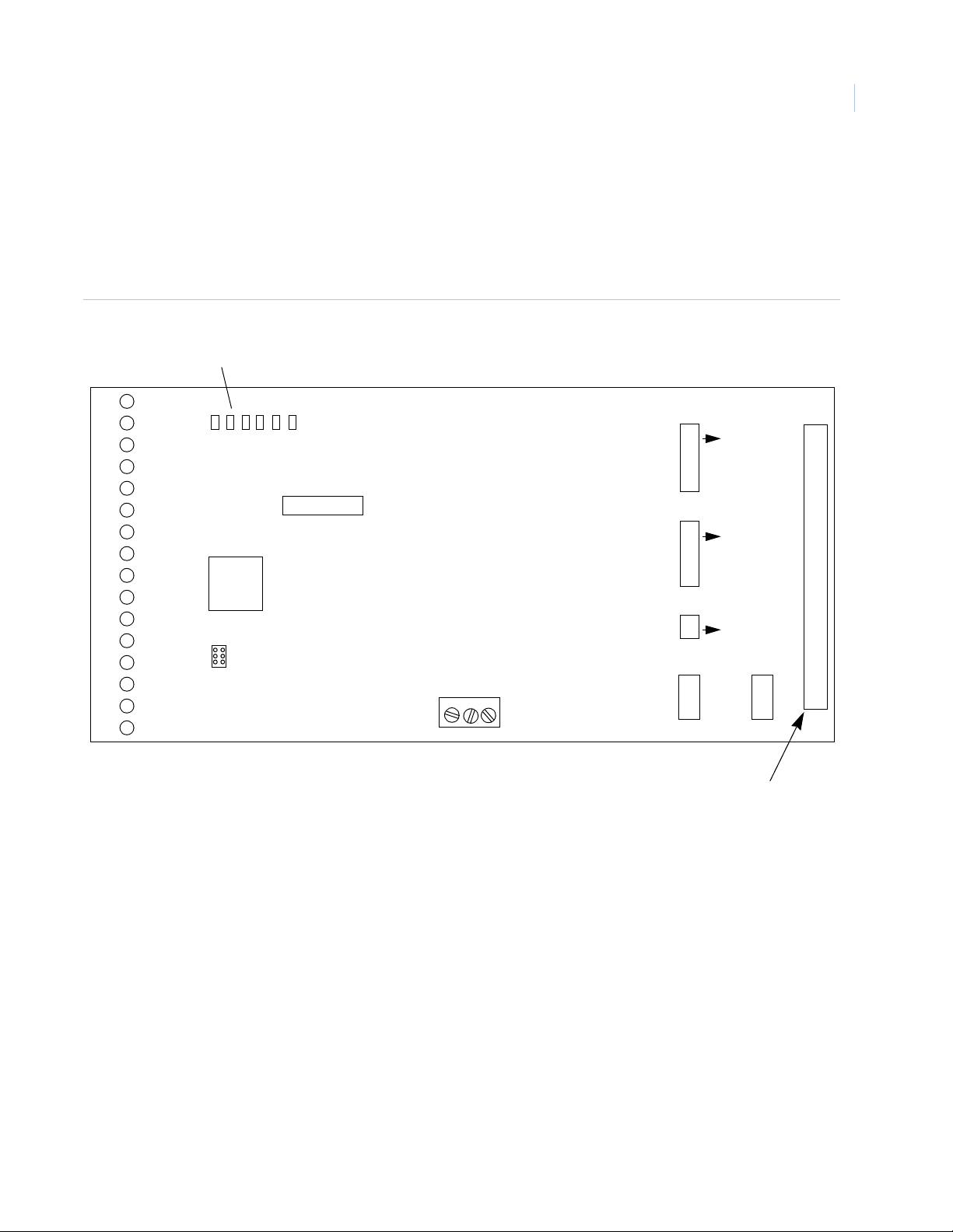
Remote Expansion Modules
Remote Input Module Circuit Board Layout
Figure 29.shows the location of components discussed in this section for Remote Input Module.
RIM Board Layout
Figure 29. RIM Component Location
LEDs
Chapter 4
69
10
11
12
13
14
15
16
1
2
3
4
5
6
7
8
9
A B C Tx Rx ON
SW1
J2
GE SECURITY
REMOTE INPUT MODULE
+12V 0V +24V
SW3
ON
1
SW4
1
ON
SW2
1
ON
K1 K2
Board Ribbon
Termination
Connector
Page 86

TOPAZ ACURT2 & ACURT4
70
Hardware Installation Guide
RIM Terminal Block Connector Pin Numbers
Tables 59 through 64 show RIM terminal block wiring connections. Refer to Ta ble 7 for applicable ACURT
controller connections and cable identifications.
RIM Connections for Expansion Port
Table 59. RIM Wiring Connections for Expansion Port 1
(Filled in by Installer)
Pin No. Term. Strip Description
1 K2 N.O. Aux Relay 2 Normally Open
2 K2 N.C. Aux Relay 2 Normally Closed
3K2 C.
4 K1 N.O. Aux Relay 1 Normally Open
5 K1 N.C. Aux Relay 1 Normally Closed
6 K1 C. Aux Relay 1 Common
7 +24V + 24 VDC In Aux Power
8GND0 V Aux Power
9 R- From ACURT TX (-) ACURT TB8-3
10 R+ From ACURT TX (+) ACURT TB8-2
11 T- To ACURT RX (-) ACURT TB8-5
12 T+ To ACURT RX (+) ACURT TB8-4
Aux Relay 2 Common
Connected to:
• For cable from the RIM to ACURT, the Belden cable numbers suggested:
Cable Color
(Filled in by Installer)
No. 9842-24 AWG for 4000 feet (1220 meters) maximum distance.
• Install one RS-485 terminator on each expansion port.
• Install RS-485 terminator on the farthest expansion module.
Note: Remote Modules should be multi-dropped with no more than a 10-foot stub.
CAUTION: The Remote Input Module requires 24 V DC power. An optional DC power supply is available. DO NOT use the
plug in power supply to power this board. It produces 24V AC Power and will damage the board.
Page 87

RIM Connections for TB1 - TB3
Zones Inputs 1-6
Table 60. RIM Wiring Connections for TB1 - TB3
Remote Expansion Modules
Chapter 4
71
(Filled in by Installer)
Pin No. Term. Strip Description
1IN1
2IN1
3IN2
4IN2
5IN3
6IN3
7IN4
8IN4
9IN5
10 IN5
11 IN6
12 IN6
Note: Refer to Figure 6 for wiring and terminating the field device to the RIM input.
Zone Input 1
Zone Input 1
Zone Input 2
Zone Input 2
Zone Input 3
Zone Input 3
Zone Input 4
Zone Input 4
Zone Input 5
Zone Input 5
Zone Input 6
Zone Input 6
Connected to:
RIM Wiring Connections for TB4 - TB7
Cable Color
(Filled in by Installer)
Zone Inputs 7-12
Table 61. RIM Wiring Connections for TB4 - TB7
Pin No. Term. Strip Description
1IN12
2IN12
3IN11
4IN11
5IN10
6IN10
7IN9
8IN9
9IN8
10 IN8
11 IN7
12 IN7
Zone Input 12
Zone Input 12
Zone Input 11
Zone Input 11
Zone Input 10
Zone Input 10
Zone Input 9
Zone Input 9
Zone Input 8
Zone Input 8
Zone Input 7
Zone Input 7
(Filled in by Installer)
Connected to:
Cable Color
(Filled in by Installer)
Page 88

TOPAZ ACURT2 & ACURT4
72
Hardware Installation Guide
Zone Input Resistance States
Table 62. Input Zone Status By Resistance
Zone Input
State
Secure 1000 1000
Active 2000 500
Open > 50000 > 50000
Short < 50 < 50
Note: Refer to Figure 6 for wiring and terminating the field device to the RIM input.
Sensor Circuit in Ohms
Normally Closed
LEDs for Alarm Zone Status
Table 63. Alarm Zone Status LED indicators.
Status of 16 Alarm points Green - Secure
LEDs 1 - 16
Red - Active
Yellow - Trouble (open or short, etc.)
RIM Connections for TB8 - TB10
Zone Inputs 13-19
Table 64. RIM Wiring Connections for TB8 - TB10
Sensor Circuit in Ohms
Normally Open
Pin No. Term. Strip Description Connected to: Cable Color
1IN13
2IN13
3IN14
4IN14
5IN15
6IN15
7IN16
8IN16
9IN17
10 GND
11 IN18
12 GND
13 IN19
14 GND
Note: Refer to Figure 6 for wiring and terminating the field device to the RIM input.
Zone Input 13
Zone Input 13
Zone Input 14
Zone Input 14
Zone Input 15
Zone Input 15
Zone Input 16
Zone Input 16
Unsupervised Zone Input 17
Ground
Unsupervised Zone Input 18
Ground
Unsupervised Zone Input 19
Ground
Page 89

Remote Expansion Modules
Setting the DIP Switches on the RIM
SW1 Switch Settings
The 8-position DIP switch (SW1) located on the RIM (Figure 29.) should be set according to Table 65.
Table 65. RIM DIP Switch Settings
Switch Number Description
SW-1 SW-2 Module address:
Off Off Addr 4
On Off Addr 5
Off On Addr 6
On On Addr 7
SW-4 Alarm Latching:
Chapter 4
73
On
Off Disables latching
SW-3 SW-5 SW-6 SW-8 Zone Termination:
Off Off Off Off 0.5K alarm, 1K safe, 2K alarm
On Off Off Off 75 ohms alarm, 150 safe, 300 alarm
Off On Off Off 1K safe, 3K alarm, 5-7K ground
On On Off Off 1K safe, 3K alarm
Off Off On Off 6.8K safe, 24K alarm
On Off On Off 1.5K safe, 3K alarm
Off On On Off 10K safe, 5K alarm
On On On Off 5K safe, 10K alarm
Enables latching – Associated LEDs for zones 1-16 will latch on alarm. Zone 18 will
reset cleared zone LEDs.
8 spares
SW2 Switch Settings for RS485 Termination
The 2-position DIP switch (SW2) located on the RIM (Figure 29.) is used to terminate the RIMs RS485
communication.
Note: The switches on the RIM can be changed while power is still applied to the board and take effect immediately.
Table 66. RIM Switch SW2 for RS485 Terminations.
Switch SW2 Description
SW1 Received Pair Termination
SW2 Transmit Pair Termination
Page 90

TOPAZ ACURT2 & ACURT4
74
Hardware Installation Guide
SW3 and SW4 Switch Settings for Input Zone Termination
The 8-position DIP switches (SW3 and SW4) located on the RIM (Figure 29.) are used to terminate the RIMs
Inputs.
Note: The switches on the RIM can be changed while power is still applied to the board and take effect immediately.
Table 67. RIM Switch SW3 for Input Terminations.
Switch SW3 Description
SW1 Zone 0 Termination
SW2 Zone 1 Termination
SW3 Zone 2 Termination
SW4 Zone 3 Termination
SW5 Zone 4 Termination
SW6 Zone 5 Termination
SW7 Zone 6 Termination
SW8 Zone 7 Termination
1
1
1
1
1
1
1
1
1. Switch in ON position will terminate the zone with 1K resister
Table 68. RIM SW4 input terminations
Switch SW4 Description
SW1 Zone 8 Termination
1
SW2 Zone 9 Termination*
SW3 Zone 10 Termination*
SW4 Zone 11 Termination*
SW5 Zone 12 Termination*
SW6 Zone 13 Termination*
SW7 Zone 14 Termination*
SW8 Zone 15 Termination*
1. Switch in ON position will terminate the zone with 1K resister
Page 91

Remote Expansion Modules
Chapter 4
Setting the Jumper on the RIM
Jumper W1 and W2 Settings
Jumpers W1 and W2 located on the RIM (Figure 29.) are used to select if 27VDC will be supplied by relays
K1 and K2 on the RIMs RS485 communication.
Table 69. RIM Jumpers W1 and W2.
Jumper Description
W1 2 & 3 (K1 Dry) 1 & 2 (K1 +27V on K1C)
W2 2 & 3 (K2 Dry) 1 & 2 (K2 +27V on K2C)
Operation LED’s on the RIM
The LED’s on the Remote Input Module will light as follows::
75
Table 70. RIM and RIM Normal LED Status
LED Description
A On when board is Communicating to ACU
BHeart 1 Hz Flash-CPU is Active
C(Always Off)
Tx Flashing when transmitting data to ACU
Rx Flashing when receiving data from ACU
ON ON when Power is applied to board
D57 ON when relay 2 is energized
D52 ON when relay 1 is energized
Status of 16 Alarm points Green - Secure
LED’s 1 - 16
Red - Active
Yellow - Trouble (open or short, etc.)
Page 92

TOPAZ ACURT2 & ACURT4
76
Hardware Installation Guide
Alarm Numbers for the Remote Input Module
Table 71. RIM Alarm Numbers for GE Security’s TOPAZ
Zone
Input
IN1 128 144 160 176
IN2 129 145 161 177
IN3 130 146 162 178
IN4 131 147 163 179
IN5 132 148 164 180
IN6 133 149 165 181
IN7 134 150 166 182
IN8 135 151 167 183
IN9 136 152 168 184
IN10 137 153 169 185
IN11 138 154 170 186
IN12 139 155 171 187
IN13 140 156 172 188
IN14 141 157 173 189
Expansion Port
Address 4
Expansion Port
Address 5
Expansion Port
Address 6
Expansion Port
Address 7
IN15 142 158 174 190
IN16 143 159 175 191
IN17 96 100 104 108
IN18 97 101 105 109
IN19 98 102 106 110
RIM
Off-line
99 103 107 111
Relay Numbers for RIM Remote Input Module
Table 72. RIM Relay Numbers
Relay
Number
K1 32 34 36 38
K2 33 35 37 39
Expansion Port
Address 4
Expansion Port
Address 5
Expansion Port
Address 6
Expansion Port
Address 7
Page 93

Remote Expansion Modules
Chapter 4
Field Testing The RIM
Field Wiring Test
After making all connec tions and prior to connec ting the ri bbon cable to the RIM, the foll owing tests should be
made. Connections should already be completed at the ACURT and external power supply.
Table 73. RIM Test Points and Voltages
From To Voltage Tolerance
GND +24V + 24 VDC 3.5 VDC
T+ T- + 4.0 VDC * 0.5 VDC
R+ R- + 2.5 VDC * 0.5 VDC
+24V Bldg. Gnd. 24 VDC 3.5 VDC
GND Bldg. Gnd. 0 VDC 0.5 VDC
T+ Bldg. Gnd. Less than 6.0 VDC N/A
77
T- Bldg. Gnd. Less than 6.0 VDC N/A
R+ Bldg. Gnd. Less than 6.0 VDC N/A
R- Bldg. Gnd. Less than 6.0 VDC N/A
Notes:
• After the first reader is connected, these voltages will modulate due to data on the line.
• Most digital voltmeters should indicate about 2.0 VDC.
Power-Up Self Test
The Remote Input Module should always be tested after installation. The indicators for the RIM are the red
LEDs located on the componen t board. See Figur e 29 for t he locat ions of LEDs. The LEDs wi ll light as shown
in Table 74.
Table 74. Power-up LED Indicators on the RIM
LED Description
A ON at power-up
B ON when successful RAM test is finished
C ON when successful PROM test and initialization completed
ON ON when power is applied
LEDs 1 - 16 All green, then all yellow, then all red
Page 94

TOPAZ ACURT2 & ACURT4
78
Hardware Installation Guide
Replacing The RIM
This procedure enables the user to replace the RIM.
WARNING: Be sure to remove all power from the RIM to avoid personal injury or damage to the unit.
1. Remove all power from the RIM (from auxiliary power source).
2. Open RIM cover to access the wiring.
CAUTION: The printed circuit boards or modules contain static-susceptible devices. Prior to handling them, be sure to
follow the two rules below to avoid damaging these devices by static electricity:
• Handle all static-sensitive components at a static-safeguarded work area.
• Transport all static-sensitive components in static-shield containers or packages.
3. Note the orientation and disconnect the ribbon cable on the RIM.
4. Note the positions of the DIP switches (Figure 29). Set the switch settings on the replacement PCB to
the required positions.
5. Note the revision level of PROM U3 located on the RIM. See Figure 29. The revision letter should be
the same or higher.
6. Release the board from the standoffs by squeezing the pit of the standoff with a pair of needle nose
pliers, then pull (gently) the RIM circuit board from each of the snap-in standoffs and remove the
circuit board.
7. Position the replacement circuit board on the snap-in standoffs until the circuit board firmly rests in
place on the standoffs.
8. Reconnect the ribbon cable removed in step 3 and set DIP switches.
9. Perform "Power-up Self-Test on the RIM" and "Normal Operation Test on the RIM" found in Section
8 of this manual.
Page 95

Remote Expansion Modules
Chapter 4
Optional Remote Relay Module
The Remote Relay Module (RRM) provides eight (8) single pole double throw (SPDT) and eight (8) double
pole double throw (DPDT) dry contact relays.
Each relay is rated 2 Amps at 30 VDC.
Three LEDs provide heartbeat feedback and online status. Nineteen hardware controlled LEDs provide
communication, power, and relay status.
Two unsupervised inputs are available for power fault and cabinet tamper.
The Remote Relay Module connects to the expansion port on the ACURT. The ACURT expansion port can
support four (4) remote modules (RIM, RRM).
Note: The Remote Relay Module requires optional 24 VDC (±15%) power supply.
WARNING: Do not use the ACURT controller, Remote Input Module (RIM) or Remote Relay Module (RRM) to switch
any voltage above 30 volts. Failure to heed this WARNING can cause death, personal injury, or damage
to unit(s).
79
Page 96
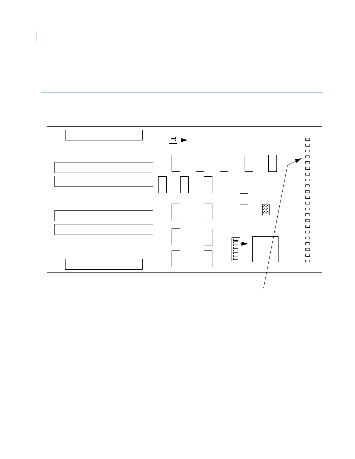
TOPAZ ACURT2 & ACURT4
80
Hardware Installation Guide
Remote Relay Module Circuit Board
Figure 30. shows the location of components discussed in this section for the RRM.
Figure 30. : Locations of Components on RRM
SW2
TB1
1 2
K12
NO NC C
TB2TB3
C NC NOK8C NC NOK8C NC NOK9C NC NO
NO NC CK7NO NC CK6NO NC CK6NO NC CK5NO NC C
TB4TB5
C NC NOK5C NC NOK4C NC NOK4C NC NOK3C NC NO
NO NC C
K7
K2
NO NC CK2NO NC CK1NO NC CK1NO NC C
TB6
GND
K13
T+ T- R+ R-
GND
K14
NO NC C
K15
NO NC C
K10
GND
GND
NO NC C
C NC NO
VIN
K16
K11
K3
1
K11 K9
ON
K16 K14
K5 K6
K3 K4
K1 K2
K15 K13
K10
ON
A
B
C
TX
K12
K8
Jumper
K7
SW1
ON
1
RRM SMT
PL-137500
Ver 3.04
COPYRITE
2004 IGYS
RX
16
15
14
13
12
11
10
9
8
7
6
5
4
3
2
1
LED Communication Status
ON - Power is applied to the board
A - On When Board is Communicating to ACU
B - Heart beat 1 Hz Flash - CPU is Active
C - (Always Off)
Tx - Flashing when transmitting data
Rx - Flashing when receiving data
Page 97

Remote Expansion Modules
Chapter 4
RRM Terminal Block Connector Pin Numbers
Tables 75 though 81 show RRM terminal block wiring connections. Refer to Table 7 for applicable ACURT
controller connections and cable identifications.
RRM Connections for Expansion port 1
Table 75. RRM Wiring Connections for Expansion port 1
Term. Strip Description Connected to: Cable Color
81
GND
GND
T+
R+
GND
GND
VIN
Notes:
I1
I2
T-
R-
Unsupervised alarm 1
Unsupervised alarm 2
Alarm common ground
Alarm common ground
Transmit + ACURT TB8-4
Transmit - ACURT TB8-5
Receive + ACURT TB8-2
Receive - ACURT TB8-3
Signal ground ACURT TB8-1
Ground Aux power
+ 24 VDC In Aux power
• ACURT2 controller has one (1) expansion port and the ACURT4 has two (2) expansion ports.
Four (4) expansion modules Remote Relay Modules (RRM) and Remote Input Modules (RIM)
may be multi-dropped on each port.
• Belden cable numbers suggested:
No. 9824-24 AWG for 4000 feet (1220 meters) maximum distance.
• Install one RS-484 terminator on each expansion port.
• Install RS-485 terminator on the farthest ACURT expansion cable.
• Remote Modules should be multi-dropped with no more than a 10-foot stub.
WARNING: The Remote Relay Module requires 24 V DC power. An optional DC power supply is available. DO NOT
use the plug in power supply to power this board. It produces 24V AC Power and will damage the board.
Page 98

TOPAZ ACURT2 & ACURT4
82
Hardware Installation Guide
Remote Relay Module Normal LED Operation
Table 76. RRM Normal LED Operation
LED Description
A ON steady when board is on-line
B Heart beat 1 flash per second
C Flashing when board is off-line
Tx Flashing when transmitting data to ACURT
Rx Flashing when receiving data from ACURT
ON ON when power is applied
LEDs 1 - 16
One LED per relay
LED is ON when relay is energized
RRM Connections for Relays 1 & 2
Table 77. RRM Wiring Connections for Relays 1 & 2
Term. Strip Description Connected to: Cable Color
K2 NO Relay 2 Normally Open
K2 NC Relay 2 Normally Closed
K2 C Relay 2 Common
K2 NO Relay 2 Normally Open
K2 NC Relay 2 Normally Closed
K2 C Relay 2 Common
K1 NO Relay 1 Normally Open
K1 NC Relay 1 Normally Closed
K1 C Relay 1 Common
K1 NO Relay 1 Normally Open
K1 NC Relay 1 Normally Closed
K1 C Relay 1 Common
Note: Relay 1-7 on the RRM is DPDT (double pole double throw) and both poles are available.
Page 99

Remote Expansion Modules
RRM Connections for Relays 3 - 5
Table 78. RRM Wiring Connections for Relays 3 - 5
Term. Strip Description Connected to: Cable Color
K5 C Relay 5 Common
K5 NC Relay 5 Normally Closed
K5 NO Relay 5 Normally Open
K4 C Relay 4 Common
K4 NC Relay 4 Normally Closed
K4 NO Relay 4 Normally Open
K4 C Relay 4 Common
K4 NC Relay 4 Normally Closed
K4 NO Relay 4 Normally Open
K3 C Relay 3 Common
Chapter 4
83
K3 NC Relay 3 Normally Closed
K3 NO Relay 3 Normally Open
K3 C Relay 3 Common
K3 NC Relay 3 Normally Closed
K3 NO Relay 3 Normally Open
Note: Relay 1-7 on the RRM is DPDT (double pole double throw) and both poles are available.
Page 100

TOPAZ ACURT2 & ACURT4
84
Hardware Installation Guide
RRM Connections for Relays 5-7
Table 79. RRM Wiring Connections for Relays 5-7
Term. Strip Description Connected to: Cable Color
K7 NO Relay 7 Normally Open
K7 NC Relay 7 Normally Closed
K7 C Relay 7 Common
K7 NO Relay 7 Normally Open
K7 NC Relay 7 Normally Closed
K7 C Relay 7 Common
K6 NO Relay 6 Normally Open
K6 NC Relay 6 Normally Closed
K6 C Relay 6 Common
K6 NO Relay 6 Normally Open
K6 NC Relay 6 Normally Closed
K6 C Relay 6 Common
K5 NO Relay 5 Normally Open
K5 NC Relay 5 Normally Closed
K5 C Relay 5 Common
Note: Relay 1-7 on the RRM is DPDT (double pole double throw) and both poles are available.
 Loading...