

Page 1
P/N 466-5234 • REV A • 06APR16
Simon® XTi Installation Guide
Device
Part number
Recommended
sensor group
Indoor motion sensor
60-639-95R, 60-80795 b
15, 17, 18, 20, 28,
or 32
Entry/exit door
60-362N-10-319.5
10
Interior door
60-362N-10-319.5
14
Door/Window sensor
60-362N-10-319.5
13
Smoke sensor
TX-6010-01-1 c
26
Glassbreak sensor
60-873-95 b
13
4-Button Key fob
600-1064-95R b
01
Device
Part number
Recommended
sensor group
Simon XT Talking
Touch Screen
60-924-3-XT-2WTTS b
60-924-RF-TS d
00, 01, 04, 05, 06,
or 07
Simon XT Talking
Touchpad
60-924-3-XT b
01
Carbon Monoxide alarm
TX-6310-01-1 b, 6006520-95 b
34
Content
Contact information......................................................... 1
Description ...................................................................... 1
Installation ....................................................................... 1
Connecting hardwired devices ....................................... 2
Wiring phone lines .......................................................... 3
Wiring the power transformer ......................................... 4
Resetting memory to factory defaults ............................. 4
Programming .................................................................. 5
Status & Settings screen ................................................ 5
Sensors ........................................................................... 7
Cleaning the touch screen ............................................ 10
Disposal ........................................................................ 10
Specifications ................................................................ 10
Regulatory information.................................................. 10
a. Not certified as a primary protection circuit for UL-listed
systems and is for supplementary use only.
b. Has not been investigated by UL.
c. Required for UL-listed residential fire alarm applications.
d. The TWTTS has been verified for use by ETL. Neither this
device nor other devices that employ the UTCFS 80 Bit
Enhanced Protocol have been investigated for use by UL.
Note: These sensor groups are only recommendations. The installer
should choose the correct sensor group for the application.
Contact information
www.utcfireandsecurity.com or www.interlogix.com
For customer support, see www.interlogix.com/contact
All trademarks are the property of their respective owners.
Interlogix is part of UTC Climate, Controls & Security, a unit of
United Technologies Corporation.
© 2016 United Technologies Corporation. All rights reserved
Description
This is the Installation Guide for the Simon® XTi system
(models 600-1054-95R-16 and 600-1054-95R-16-CN).
Table 1: Sensors and recommended sensor groups
CAUTION: Do not use outdoor motion sensors for
intrusion protection.
ATTENTION: N’utilisez pas des détecteurs de mouvement
extérieurs pour détecter les intrusions.
Safety information
IMPORTANT SAFETY INFORMATION. READ ENCLOSED
WARNINGS AND SAFETY INFORMATION.
WARNING: CHOKING HAZARD. The product accessory
bag contains items that could be choking hazards. Please keep
away from small children.
AVERTISSEMENT: Le sachet d'accessoires produit contient
des éléments qui pourraient être les dangers d'étouffement.
Veuillez garder hors de la portée des jeunes enfants.
WARNING: Disconnect panel power before servicing.
AVERTISSEMENT: Débrancher l'alimentation du panneau
avant l'entretien.
CAUTION: Use static electricity precautions when handling
electronic components.
ATTENTION: Utiliser les précautions de l'électricite statique
lors de la manipulation des composants électroniques.
Page 2
Installation
Panel location
Locate the panel where alarm sounds can be heard and where
the panel will be easily accessible for operation. Do not install
the panel near a window or door where it can be reached
easily by an intruder.
Mounting
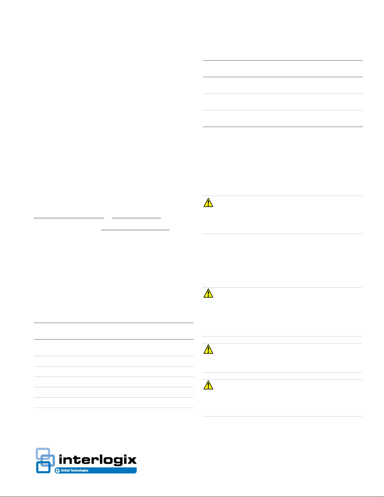
Figure 1: XTi chassis and trim ring
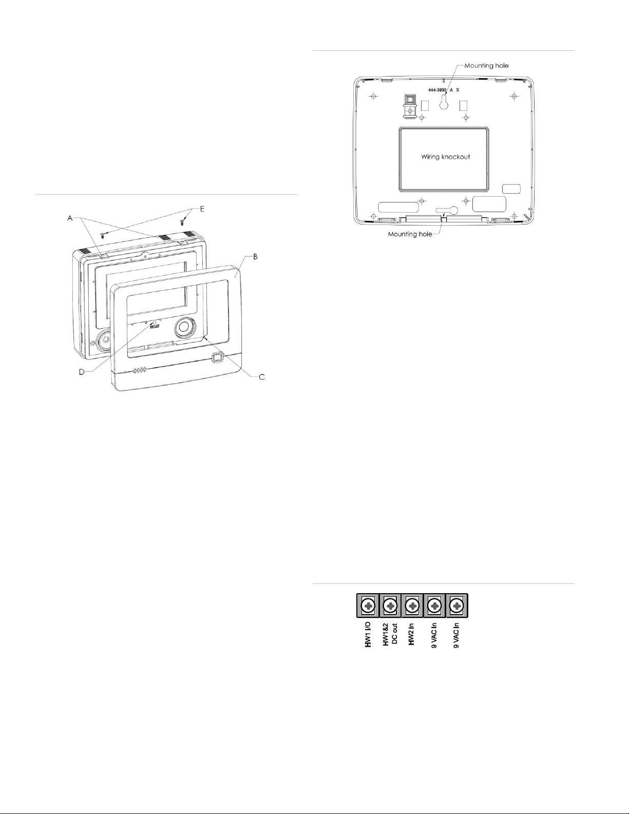
Figure 2: Mounting holes
7. Secure the mounting screws (provided) to the locations on
the wall marked in step 6. Do not tighten the screws.
Leave enough clearance to mount the mounting plate.
Note: Use wall anchors if no studs are present.
8. Mount the mounting plate to the wall. Insert the top
mounting hole first, then the bottom hole. Adjust the fit to
make sure the mounting plate is level. Hold the mounting
plate in place and tighten the screws.
To mount the panel on a wall:
1. Lay the panel flat on a table.
2. Remove trim ring (B in Figure 1 above) from panel by
lifting at notch (C in Figure 1 above).
3. Separate the panel chassis from the mounting plate by
lifting up on the tabs (A in Figure 1 above) and swinging
the chassis open.
4. Choose a panel location.
5. Run all necessary power, phone, siren, and hardwired
contact wires to the desired panel location.
When choosing the AC outlet location for the AC power
transformer, make sure the outlet is not controlled by a
switch or that it is not part of a ground fault circuit interrupt
(GFCI).
6. Hold the mounting plate against the wall and mark the
mounting hole locations (Figure 2 below) with a pencil.
Note: Mark both mounting holes in the middle of the
mounting slot. This will allow better adjustment of the
panel before securing it to the wall.
9. Hang the panel chassis on the mounting plate at the
plastic hinges, swing the chassis up to the mounting plate
and engage at the tabs (A in Figure 1 above).
For a UL Listed installation, secure the tabs using the
provided screws (E in Figure 1 above).
10. Reattach the trim ring.
Connecting hardwired devices
The panel has five screw terminals, two battery terminals, and
two telephone connections. The screw terminals connect the
AC power, sirens, and/or hardwired detectors.
Figure 3: Wiring terminals
Program sensors and devices before you install them. Follow
the instructions in “Sensors” on page 7 to add the sensors to
panel memory.
2 Simon® XTi Installation Guide
Page 3
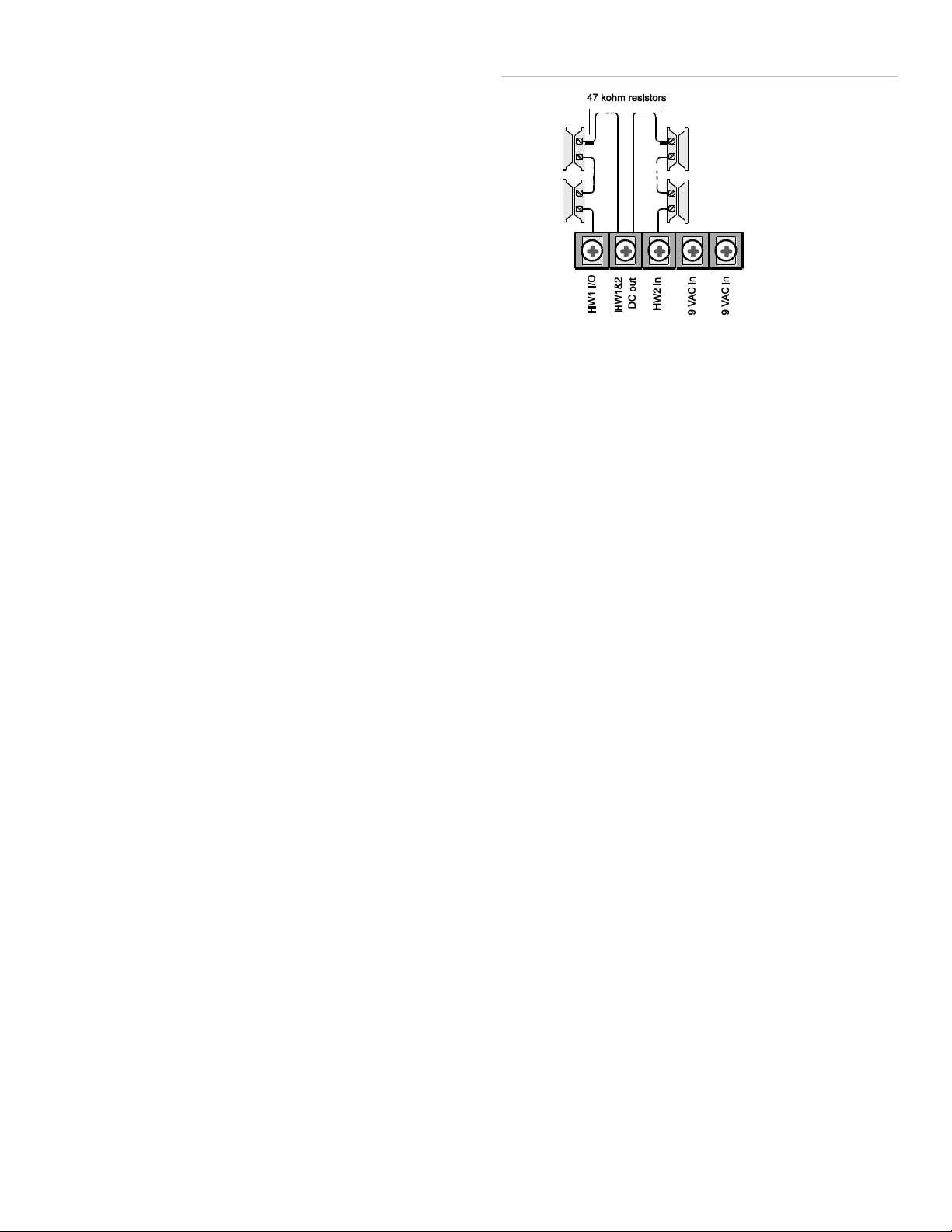
The HW1 I/O terminal is dual purpose and can be used for
either siren or hardwired contact connections. The HW2 in
terminal is an input only.
Interior sirens
From the factory, the HW1 I/O input (terminal 1) is set up for
interior siren operation (status and alarm sounds). The HW1&2
DC out (terminal 2) provides the positive (+) voltage.
Note: The total current available from the HW1&2 DC out
terminal is 250 mA at up to 120ºF (49ºC). A 24-hour battery
standby for UL requirements will be met with a maximum load
of 250 mA.
With Hardwired Siren Supervision turned on, sirens connected
to HW1 I/O are supervised and require a 4.7-kohm resistor in
the circuit. If this terminal is not used, turn Hardwired Siren
Supervision off.
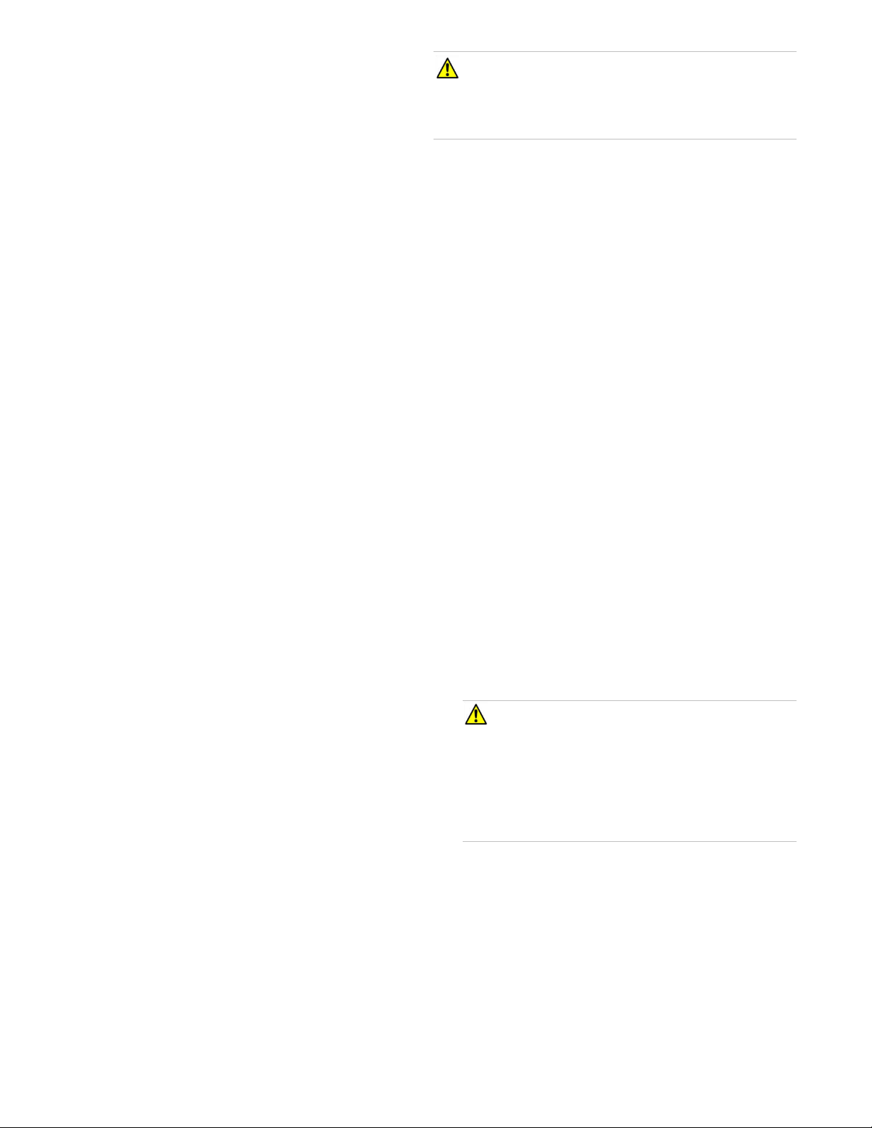
Figure 4: Normally closed hardwired reed switches
Note: Do not install the resistor at the panel terminals. This
does not provide supervision of the wire.
Exterior sirens
For an exterior siren, change the HW1 setting in the System
Options programming menu. See wiring diagram.
Note: Not investigated for and may not be used in a UL Listed
installation.
Hardwired contacts
You can connect hardwired reed switches (normally closed
loop only) to HW1 I/O (if not being used for a hardwired siren)
and/or HW2 in (terminal 3).
Connect only normally closed (NC) reed switches to HW1 I/O
and/or HW2 in. Other types of hardwired detectors should not
be used.
The total resistance of the wired loop must not exceed 3 ohms.
This allows you to use up to 200 ft. (61 m) of two-conductor,
22-gauge stranded wire.
Connect hardwired reed switches to the panel using a 47-kohm
resistor (not a 4.7-kohm resistor) as shown in Figure 4 below.
The resistor must be connected at the last switch in the circuit.
Wiring phone lines
You can connect a phone line to the panel for systems
monitored by a central monitoring station or systems that notify
users by a voice event notification.
DSL (digital subscriber line) allows the use of multiple devices
on a single phone line simultaneously. For DSL environments,
connect the panel line-in jack to an available phone jack on the
premises. You might also need an inline filter to ensure panel
reporting is successful.
Note: Avoid connecting the panel to a standard phone (voice)
line, as other devices on the line can prevent reports from
going through.
Full line seizure
Full line seizure allows the panel to take over (seize) the phone
line, even if another device on the line is in use. This method
requires that the panel be wired before all other phones,
answering machines, computers, or other devices on the
phone line. You may need to verify the line seizure for UL
installations.
Use the RJ31X (CA-38A) jack when wiring for full line seizure.
You can then quickly and easily disconnect the panel from the
phone line in case the panel disables the phone line due to a
malfunction.
To wire full line seizure with an RJ31X:
1. Run a four-conductor cable from the premises Telco block
to the RJ31X.
2. Connect the four-conductor cable wire to the RJ31X.
3. Disconnect the green and red premises phone jack wires
from the Telco block and splice them to the four-conductor
Simon® XTi Installation Guide 3
Page 4
cable black and white (or yellow) wires. Use weatherproof
wire connectors for these splices.
4. Connect the four-conductor cable green and red wires to
the Telco block TIP (+) and red to RING (-) posts.
5. Connect the phone cord included with the panel to the
RJ31X and the panel LINE jack.
CAUTION: Do not connect the battery until you are ready
to power up the panel.
ATTENTION: Ne branchez pas la batterie tant que vous n’êtes
pas prêt à mettre le panneau sous tension.
Resetting memory to factory defaults
Full line seizure wiring with one premises phone
If a single phone is all that exists on the premises, full line
seizure can be accomplished without an RJ31X.
1. Disconnect the phone from the premises phone jack and
plug it into the panel PHONE jack. This jack is
disconnected automatically whenever the panel reports.
2. Connect the included phone cord to the panel LINE jack
and the premises phone jack.
If a customer adds phones or other phone devices to another
phone jack, full line seizure no longer exists. Inform them to
contact you if they want to add a phone or other device so that
you can rewire for full line seizure by adding an RJ31X.
Wiring the power transformer
Connect the power transformer to the two 9 VAC in terminals
(4 and 5) on the panel. Do not plug in the transformer at this
time. When applying power to the panel, connect the battery
first, and then plug in the AC power transformer. This
sequence prevents a battery fault condition.
If you need to reset memory to factory defaults, follow the
steps below.
To reset the panel to factory defaults:
1. Remove the trim ring.
2. Open the panel chassis.
3. Unplug the transformer and disconnect the battery.
4. Press and hold the reset button (D in Figure 1 on page 2)
on the center of the panel.
5. Plug in the transformer to the panel while holding the reset
button and keeping the panel cover open.
6. Release the button.
7. Plug in the battery and close the panel chassis.
8. Replace the trim ring.
Applying AC power
Make sure the outlet is not controlled by a switch or that it is
not part of a ground fault circuit interrupt (GFCI).
Note: System can only be powered up using AC power, not
battery power. The red battery icon may appear when the
system first powers up and will disappear after some time.
To remove and install the backup battery (6 VDC, 2.1 Ah):
Note: It is recommended that the backup battery be replaced
every 3-5 years.
1. Remove AC power from the panel.
2. Disconnect the existing battery from the battery connector.
3. Remove the existing battery by reaching under the battery
with a finger and pulling up.
Note: Do not try to push the plastic latch back to remove
the battery.
4. Insert the new battery into the battery compartment and
snap into place.
5. Plug the battery connector into the panel.
Note: For Canadian installations, plug the transformer into the
wall outlet.
1. Remove the center screw from the outlet cover plate and
hold the cover plate in place.
WARNING: Use extreme caution when securing the
transformer to a metal outlet cover. You could receive a
serious shock if a metal outlet cover drops down onto the
prongs of the plug.
AVERTISSEMENT: Faite preuve d’une extrême prudence
quand vous fixez le transformateur sur une plaque
métallique. Vous pourriez recevoir un choc grave si la
plaque métallique touche aux broches du transformateur.
2. Plug the transformer into the lower receptacle of the outlet
so that the hole in the transformer tab lines up with the
outlet cover screw hole.
3. Insert the cover plate screw through the transformer tab
and the outlet cover plate. Tighten the screw.
Note: Upon initial installation, the battery may not be fully
charged for as long as 36 hours. A low battery icon will be
present and trouble beeps will sound until the battery is
4 Simon® XTi Installation Guide
Page 5

sufficiently charged. After the initial charge, should the panel
Item
Description
Piezo siren
Provides alarm beeps and status beeps. Fire and
intrusion alarm beeps are always played at high
volume, while the volume of status beeps is
programmable.
Touch screen
Provides a graphical user interface for
programming and system operation.
Microphone
Used to communicate with the central monitoring
station after an alarm.
Speaker
Provides voice output and sounds key beeps.
The panel speaks arming level change, system
status, and voice chime sensor trips. The panel
voice is also used for voice reporting and remote
phone control.
To access the emergency screen and select the
appropriate emergency icon (Panic, Police, or
Fire), press EMERGENCY in the top left corner of
the screen.
Time
Displays the current system time.
Depicts the status of the AC power and battery. A
green power cord icon represents AC power to
the system. A red battery icon represents low
battery power to the system. A green battery icon
represents a charged battery.
This will appear on the home screen in the event
of an alarm. Messages will also display on this
icon describing what caused the alarm. Press this
icon to cancel the alarm.
Item
Description
These four icons depict the status of the sensors
installed in your system.
A green check indicates sensors are closed or no
recent activity detected. A red exclamation
indicates sensors are open or recent activity has
been detected.
Pressing these icons will open a new screen to
provide more detail.
If the icon shows N/A, your system is not
configured to support that type of sensor.
Press this icon to access the Arming Screen.
One of these icons will display depending on your
arming level. Press to turn off intrusion/burglary
protection for your system. Only
intrusion/burglary sensors are disarmed.
Environmental sensors, such as smoke and
carbon monoxide detectors, stay active at all
times. Enter your code in the keypad screen that
appears. If you enter an incorrect code, press the
Clear icon and enter the correct code.
Press to access the Status & Settings screen.
lose AC Power and experience a low battery
condition, the icon will appear and trouble beeps will sound
unless silenced. You can silence trouble beeps by:
• Arming or disarming the system.
or
• Pressing the STATUS & SETTINGS icon and
pressing LISTEN next to Panel Status.
This will disable the sounder for 4 hours but the trouble
indication will remain until the battery is recharged.
Programming
The control panel provides the main processing unit for all
system functions. The programming of system options and
features is menu-driven.
Table 2 below describes the panel’s programming keys and
features.
Table 2: Simon® XTi features and home keys
Simon® XTi Installation Guide 5
Arming errors
If you select an arming option on the Arm screen, and there is
an arming problem, an arming error message will appear at the
bottom of the screen, indicating what the problem is and how
to correct it. For example, you might see a message that
indicates that you need to close the front door.
Correct the problem as indicated or press Bypass. You will see
the arming countdown message at the bottom of the screen.
You can touch Cancel and enter your code to stop the arming
process.
Status & Settings screen
Entering and exiting the Status & Settings screen
To enter the Status & Settings screen:
Press the Status & Settings icon on the lower right of
the home screen.
To exit the Status & Settings screen:
Press Close to exit the Status & Settings screen and navigate
up one level.
Note: The system will automatically return to the main screen
after a period of inactivity.
A gold icon indicates an option is selected.
A blue icon indicates an option is not selected.
Page 6

Status & Settings Screen navigation
Option
How to view
Event History
Press the Show icon to view system events.
Note: If a # appears in the Event History list, the
event was not sent to the central station.
Direct Bypass
Press the Select icon to enter the sensor bypass
screen.
Panel Status
Press the Listen icon to listen to the status of
your security system. Press Clear to clear the
status.
Chime
Press the On/Off icon to set the chime feature
On/Off.
Note: This option may or may not appear
depending on panel programming.
Special Chime
Press the On/Off icon to set the special chime
feature On/Off.
Note: This option may or may not appear
depending on panel programming.
Lights
Press Control to access the Light screen. From
there you can turn On/Off programmed lights.
Note: Has not been investigated by UL.
Door Locks
Press Control to access the Door Lock screen.
From there you can lock/unlock programmed
door locks.
Note: Has not been investigated by UL.
Voice Volume
Press the arrows to adjust the speech volume
level.
Beep Volume
Press the arrows to adjust the beep volume level.
Brightness
Press the arrows to adjust the screen’s
brightness.
Default Screen
Use this feature to set this panel’s screen saver
mode. Select “Blank” to have the screen and LED
go dark after a period of inactivity. Otherwise, the
default will be the Home screen and the screen
will always be lit. If AC power is lost, the screen
will go blank after 2 minutes of inactivity to
maximize battery life.
Note: The screen will automatically go blank at
2:00 am daily for 60 minutes.
Calibration
Press the Show icon to enter the calibration
screen. This screen will allow you to recalibrate
the touch screen.
Help
Press the Help icon to access the Help menu.
Set Date/Time
Press Enter to set the date and time.
System Tests
Press Enter to perform a sensor test or system
download.
Option
How to view
Programming
Press the Access Codes icon to change existing
or add new access codes.
Press the Security icon to turn downloader
enable on/off and to set the account number.
Press the Phone numbers icon to change existing
or add new phone numbers.
Press the Phone Options icon to access the
following phone options:
• Manual phone test
• Fail to communicate
• DTMF dialing
• 300 BPS enabled
• Ring hang ring
• Dialer delay
• Call waiting code
Press the Sensors icon to access the learn
sensor, edit sensor, and delete sensor options.
Press the Reporting icon to access the following
reporting options:
• Opening report
• Closing report
• Force armed report
• AC power failure report
• Panel low battery report
• Sensor alarm restoral report
• 24 hour sensor tamper
• Supervisory tamper report
• No usage report
• Swinger shutdown
• Programming report
• Fire alarm verification
Press the Timers icon to access the following
timers options:
• Entry delay
• Exit delay
• No activity timeout
• Audio phone test
• Supervisory time
• Alarm cancel window
• RF timeout
• Fail to open time
• Fail to close time
• Siren timeout
• Unvacated premises
• Smoke supervision
Press the Touchpad Options icon to access the
following options:
• Keyfob no delay
• Panic alarms
• Remote TP arming
1. Press the up/down arrows to scroll through the pages.
2. Press an icon to change the value of an option or enter a
3. Press Close to return to the previous screen.
Table 3: Status & Settings screen structure
(See Table 3 below for Settings screen structure).
subscreen.
6 Simon® XTi Installation Guide
Page 7

Option
How to view
Press the System Options icon to access the
following system options:
• RF jam detect
• Demo mode
• HW1 function
• 24 hour clock
Press the Siren Options icon to turn on/off the
following options:
• Panel piezo beeps
• Panel voice
• Panel piezo alarm
• Trouble beeps
• Voice chime
• HW siren supervision
• Silent police panic
• Alarm report verify
Press the Audio Verification icon to access the
following audio verification options:
• Audio mode
• Fire shutdown
• Fire enabled AVM
• Panic talk
• VOX receiver gain
• VOX microphone gain
• VOX microphone gain range
• Manual microphone gain
Press the System Tests icon to perform a sensor
test, communication test, or system download
test.
Version
Displays the system’s firmware version, touch
screen version, and copyright information.
Code
Description
Dealer
code
You can use the dealer code to program all system
functions, including high-security options that are not
accessible with the installer code if it is different from the
dealer code. Depending on how the access code is set, the
default dealer access code is 654321, 54321, 4321 (factory
default), or 321. This code can be used for all programming.
Code
Description
Installer
code
Depending on how the access code is set, the default
installer code is 654321, 54321, 4321 (factory default), or
321. This code is limited to changing all but the following:
Dealer code, code length, downloader code, phone lock,
phone #1, phone #2, phone 1 report mode, phone 2 report
mode, HW1 function.
Access codes
Function
Default
Description
Dealer
code
4321
You can use the dealer code to program all
system options, including high-security
options that are not accessible with the
installer code if it is different from the dealer
code. Changing the dealer code to differ from
the installer code will prevent the installer
from viewing certain fields.
If you change the dealer code and enter
program mode with the installer code, the
installer will no longer be able to see the
following: code length, downloader code,
phone lock, phone #1, phone #2, phone 1
report mode, phone 2 report mode, HW1
function.
Installer
code
4321
You can use the installer code to program
most installer options, except for high-security
dealer options.
Master
code
1234
You can use the master code to arm/disarm
the system and to enter user programming
and bypass sensors.
User
codes 1
to 8
Blank
You can use the user codes to arm/disarm the
system.
Duress
code
Blank
You can use the duress code in place of the
master or user code to cause a silent alarm.
Code
length
Four digits
Codes can be three to six digits long.
Table 5 below describes the Access code menu programming
options.
Table 5: Access codes
Access Programming screen
1. From the Status & Settings screen, press the down arrow
to scroll to the Programming option.
2. Press Enter.
3. Enter the dealer or installer code (see Table 4 below) and
press OK.
Note: You have four seconds between number presses to
enter the code or you will be returned to the home screen.
Note: Do not remove the panel power within 30 seconds of
exiting program mode.
Table 4: Simon® XTi programming codes
Simon® XTi Installation Guide 7
Sensors
These instructions describe how to add (learn) sensors,
touchpads, and other system devices into panel memory. The
panel recognizes a sensor when you press a sensor program
icon, press and release a tamper switch, press a sensor test
button, or put a sensor into alarm. Table 6 on page 8 describes
the programming method for each device.
Note: If you are installing a sensor on a gun case, jewelry box,
or a similar case, and the sensor is active in level one, you
must direct bypass the sensor to avoid putting the panel into
alarm when the sensor and the magnet are separated.
Page 8

Mounting Recommendations:
Device
To program
Door/window
sensor
Press the button on the top of the sensor (cover
removed) or trip the tamper.
Motion sensor
Press the button on the back of the sensor
(mounting plate removed) or trip the tamper.
Smoke detector
Trip the tamper, press the test button, remove the
detector from its base, or put the smoke detector
into alarm.
Hardwired
sensor
Separate the sensor from its magnet.
CO alarm
Trip the wall tamper by removing the sensor body
from the mounting plate.
Simon XT
talking touch
screen
1. Press the Settings icon.
2. Press the Down arrow until the Clear and Enroll
icon appears.
3. Press the Clear and Enroll icon. The touch
screen should indicate it is waiting for enrollment.
Simon XT
talking
touchpad
Press the Lights off button on the touchpad six
times in rapid succession. On the sixth press, the
touchpad makes a longer beep.
Key fob
Press the lock and unlock buttons at the same time.
3. Press Sensors.
• Where possible, install sensors within 100 feet (30 m) of
the receiver. While a transmitter and receiver combination
may have an open-air range of 500 feet (152 m) or more,
the environment at the installation site may have a
significant effect on operational range. Changing a sensor
or receiver location can improve wireless communication.
• Avoid mounting sensors or receivers in areas where they
will be exposed to moisture or where the operating
temperature range will exceed the specified range (10 to
120 °F).
• Avoid mounting the sensor or receiver in areas with a
large quantity of metal or electrical wiring. For example:
within 1 meter of AC distribution panel (fuse box), HVAC
duct work.
• Avoid mounting the sensor or receiver directly on metal.
• The Simon® XTi system should not be mounted within 3
meters of any other RF equipment (RF music system
transmitter, wireless router/modem, etc.).
Note: Refer to specific sensor installation instructions for
complete operation and testing details.
Table 6: Device programming
4. Press Learn Sensor.
5. Trip the sensor (see Table 6 above). The Edit Sensor
screen will appear. If no further action is required (change
sensor name, number, or group) proceed to step 8. To
exit, press Close repeatedly.
6. To change the sensor name, number, or sensor group
press the appropriate Edit icon and modify the value. To
change the sensor text, press the appropriate Edit icon,
then choose the item you would like to change.
7. Press Save to keep the new sensor, or Cancel to abort
learning this sensor into the system (both of these choices
will return you to step 5).
8. To exit, press Close repeatedly.
Sensor Naming
Please use the following guide when naming sensors:
• Sensor names must have the word “window” or “door”
from the text library to interact with the touch screen Door
and Windows icons on the Main screen.
• On the Edit Sensor name screen in programming, default
the screen to list and not keypad. This gives the user the
list of possible sensor names.
To learn (program) a sensor:
1. From the Programming screen, enter the access code
from the codes listed in Table 5 on page 7. The display
shows each entered access code digit as a dot.
• The Motion icon is controlled by sensors that are
programmed into the following groups: 15, 17, 18, 20, 28,
or 32.
• The Property icon is controlled by the following sensors:
• All sensors learned into Group 43.
• Sensors that are not named “window” or “door”.
• Sensors not learned into the Motion groups.
• Sensors that are named keyfob, keychain or
touchpad.
Sensor Testing
Test the sensors after all programming is completed and
whenever a sensor-related problem occurs.
Note: While the sensor test is a valuable installation and
service tool, it only tests sensor operation for the current
conditions. You should perform a sensor test after any change
in environment, equipment, or programming.
Notify the central station you will be performing a test prior to
starting the test.
To test the sensors:
1. Place all sensors in their secured (non alarm) state.
2. Press OK. You are now in the programming screen.
8 Simon® XTi Installation Guide
Page 9

2. Access the System Test screen through the Programming
Sensor
Instructions
Minimum
packets
required
Hardwire
contact
Open the hardwire contact.
1
Door/window
Open the secured door or
window.
6 of 8
Carbon
monoxide alarm
Press and hold the Test/Hush
button (approximately 5
seconds) until the unit beeps
two times, and then release the
button.
6 of 8
Glassbreak
Test with an appropriate glass
break sensor tester.
6 of 8
Motion sensor
Avoid the motion sensor field of
view for 5 minutes, and then
enter its view.
6 of 8
Smoke
Press and hold the test button
until the system sounds
transmission beeps.
6 of 8
Key fob
Press and hold the Lock and
Unlock buttons simultaneously
for 3 seconds.
6 of 8
Simon XT
talking
touchpad
Press and hold the two
Emergency buttons
simultaneously for 3 seconds.
6 of 8
Simon XT
talking
touch screen
For sensor testing a 1.0. touch
screen, press and hold the
Emergency icon for 5 seconds.
For sensor testing a 1.1 or
greater touch screen, press the
Settings (gear) icon, scroll
down, and then press the RF
Test icon.
6 of 8
Screen, and then press OK.
3. Enter the dealer or installer code and press OK.
4. Press Sensor Test.
5. All learned in sensors will be displayed on this screen.
Press the arrows to scroll through the pages.
6. Press Close repeatedly to exit.
Sensor Test Failure
If sirens do not beep when a sensor is tripped, use an RF
Sniffer (60-401) test tool to verify that the sensor is
transmitting. Constant beeps from the RF Sniffer indicate a
faulty sensor. Replace the sensor.
Test your sensors by tripping them one at a time. The
panel will display the number of transmissions received
from sensors you trip. See Table 7 below for specific
instructions on how to trip each sensor type.
The panel sounds beeps, and the display identifies the
tripped sensor and the number of RF packets received.
Each beep represents one RF packet. Count the number
of beeps and refer to Table 7 below for minimum
requirements. The panel displays Sn #, Name, and
Rounds Detected (Packets). Scroll through to make sure
all sensor have been tested.
Table 7: Sensor tripping instructions
If possible, locate sensors within 100 ft. (30 m) of the panel.
While a sensor may have a range of 500 ft. (152 m) or more
out in the open, the environment at the installation site can
have a significant effect on transmitter range. A change in
sensor location may help overcome adverse wireless
conditions and can potentially be accomplished by the
following:
• Reposition the sensor
• Relocate the sensor
• If necessary, replace the sensor
To reposition a sensor:
1. Rotate the sensor and test for improved sensor
communications at 90 and 180 degrees from original
position.
2. If poor communication persists, relocate the sensor.
To relocate a sensor:
1. Test the sensor a few inches from the original position.
2. Increase the distance from the original position and retest
until an acceptable location is found.
Simon® XTi Installation Guide 9
3. Mount the sensor in the new location.
4. If no location is acceptable, replace the sensor.
To replace a sensor:
1. Test a known good sensor at the same location.
2. If the transmission beeps remain below the minimum level,
avoid mounting a sensor at that location.
3. If the known-good sensor functions, contact UTC Fire &
Security for repair or replacement of the problem sensor.
Sensor Testing Notes:
• Conduct sensor test in all possible environmental
conditions (For example: interior doors open and closed,
HVAC system on and off, wireless music system turned on
and off).
• Conduct sensor test whenever changes are made to the
installation environment that may impact RF performance
(For example: mirrors installed, metal backed wall paper,
addition of other RF equipment).
Page 10

• Sensor testing should be done before and after permanent
Power
9 VAC, 60 Hz, 25 VA transformer minimum
Rechargeable battery: 6.0 VDC, 2.1 Ah NIMH.
Maximum battery charging current is 120 mA.
Once the battery reaches a low battery
condition, a trouble signal will be annunciated,
indicating that the battery may no longer
support a full alarm load.
When fully charged, the battery will operate the
panel without AC power for 24 hours with the
panel in a normal, standby condition, followed
by 5 minutes in full alarm condition (including
the maximum specified auxiliary load of 250
mA).
Radio frequency
319.5 MHz
Storage temperature
-29 to 140ºF (-34 to 60ºC) without battery
14 to 86ºF (-10 to 30ºC) with battery one year
shelf life
Operating
temperature
32 to 120ºF (0 to 49ºC)
Maximum humidity
85% relative humidity, noncondensing
Auxiliary power
Unregulated 4.0 to 12.3 VDC, with a maximum
of 250 mA
mounting.
Comm Testing
If Comm Test is not finished, it will continue to run even if you
exit program mode.
Note: Complete panel programming before performing comm
testing.
To perform a comm test:
1. Enter the Status & Settings menu.
2. Scroll until System Tests is listed, Press Enter.
3. Enter your master code and press OK.
4. Press Comm Test.
The panel displays if the comm test was successful or not.
Central station communication
After performing sensor tests, check that the system is
reporting alarms successfully to the central station.
Note: The communication with the central station test must be
done while NOT in programming mode.
To verify alarm reporting:
1. Call the central station and tell the operator that you will be
testing the system.
2. Arm the system.
3. Test an emergency panic icon and trip at least one sensor
of each type (fire, intrusion, etc.) to verify that the
appropriate alarms are working correctly. There is a 30
second delay.
4. When you finish testing the system, call the central station
to verify that the alarms were received.
Cleaning the touch screen
If necessary, use a soft cloth to clear smudges on the touch
screen. Do not use glass cleaner on the touch screen.
Disposal
Dispose of all equipment is accordance with local requirements
Specifications
10 Simon® XTi Installation Guide
Regulatory Information
Some installation may require configurations dictated by
city/state codes, insurance, or Underwriter’s Laboratories (UL).
This section describes the various component and
configuration listings.
Basic system:
• Control panel: Backup battery 6 V 2.1 Ah (34-070)
• Standard Class 2, 9 VAC, 25 VA power transformer (UTC
Fire & Security part 22-155) or Standard Class 2, 9 VAC,
25 VA power transformer (UTC Fire & Security part 22-
165) or Standard, Class 2, 9 VAC, 30 VA (UTC Fire &
Security part 22-153).
• Hardwired siren (13-374)
Household burglary alarm system unit (UL 1023), basic system
plus the following:
• Hardwired magnetic contact (1038T) or wireless learn
mode door/window sensor (60-670-95R or
60-362N-10-319.5 or 60-362N-11-319.5)
• Panel piezo beeps set to on
• Entry delay set to 45 seconds or less
• Exit delay set to 60 seconds or less
• RF time-out set to 24 hours
• Control panel alarms turned on
• Auto arm set to on
• Siren timeout set to 5 minutes or more
• Trouble beeps set to on
• RF jam detect set to on
• Hardwired siren supervision set to on
• Exit extension set to off
• Quick exit set to off
Page 11

Household fire warning system (UL 985), basic system plus the
Function
Default setting
Required setting
Entry delay
30 seconds
30 to 240 seconds
Exit delay
60 seconds
45 to 240 seconds
Dialer delay
30 seconds
15 to 45 seconds
Auto arm
On
On
Un-vacated premises
On
On
Call waiting
Off
On if reporting to
central station and
customer has call
waiting service
Alarm cancel window
6 minutes
6 to 255 minutes, Off
System test
Enabled
Enabled
Communication test
Enabled
Enabled
Exit extension
On
On
Swinger shutdown
On (one trip)
On (one trip)
Function
Default setting
Required setting
Fire alarm verify
Off
On
Duress/panic code
Disabled
Disabled
Cross zone
Disabled
Disabled for zones
with high probability of
false alarms
Function
Operation
Silent exit
All annunciators enabled
Remote arming exit time and
progress annunciation
All annunciators enabled
Abort annunciation
Enabled
Cancel report annunciation
Enabled
Recent closing
Enabled (2-minute window)
Exit error
Enabled
Restoration of power
Panel resumes operation in same
arming state and disregards alarm
signals from sensors for the first
60 seconds after power
restoration
Cancel alarm
Enter code only
following:
• Wireless smoke sensor 60-848-02-95, TX-6010-01-1
learned into sensor group 26.
• Panel piezo beeps turned on
• Control panel alarms set to on
• Siren timeout set to 4 minutes or more
• Trouble beeps set to on
• RF jam detect set to on
• Hardwired siren supervision set to on
• Smoke supervision set to on
UL 1635 digital alarm communicator system the following
settings are required only if the system is set up for central
station reporting:
• Phone mode 1 set to “All SIA” or “All CID”
• Automatic phone test set to 001
• RF timeout set to 4 hours
• AC power failure report set to on
• CPU low battery report set to on
• Fail to communicate set to on
• Entry delay plus the dialer delay must not exceed 60
seconds
Table 9 below describes nonprogrammable (hard-coded)
system operation, as required to meet ANSI-SIA CP-01.
Table 9: Nonprogrammable system operation
SIA system requirements
Verified to SIA CP-01-2007 by ETL, basic system, plus if
multiple annunciations are required, use hardwired siren 13-
046.
Note: For UL 1635 installations, entry delay plus dialer abort
delay must not exceed 60 seconds.
Table 8 below describes programming requirements to meet
ANSI-SIA CP-01.
Table 8: SIA setting requirements
Central station reporting
Note: The panel shall not be set or programmed to place a call
to a police station number that has not been specifically
assigned by that police station for such service.
CAUTION: If call waiting is used on a non-call waiting line,
successful connection to the central station may be prevented.
ATTENTION: Si l'appel en attente est utilisé sur une ligne
d'attente non - appel, connexion réussie à la station centrale
peut être empêché .
The panel has been tested with the following central station
receivers using SIA and Contact ID reporting formats:
Before beginning installation, installers must verify that the
central station is equipped with the following receivers:
• Radionics D6600 central station receiver
• Sur-Gard central station receiver with models SG-DRL2A
and SG-CPM2
• CS5000 digital alarm communicator receiver
Simon® XTi Installation Guide 11
Page 12

UL Canada listed installations
This section describes the requirements for CUL (UL Canada)
listed installations.
Canadian standards CSA certified accessories:
• Standard Class 2, 9 VAC, 30 VA power transformer (UTC
Fire & Security model 22-153-CN) or Standard Class 2, 9 VAC,
25 VA, (UTC Fire & Security model 22-155-CN) or Standard
Class 2, 9 VAC, 25 VA, (UTC Fire & Security model 22-165CN).
Residential burglary alarm system unit (ORD-C1023-1974):
basic system as described for UL 1023 listed installations plus:
• Hardwired magnetic contact (1038T) or wireless learn
mode door/window sensor (60-670)
• Siren timeout set to six minutes or more
Residential fire warning system control unit (ULC-S545-M89):
basic system as described for UL 985 listed installations plus:
• Wireless smoke sensor 60-848-02-95, TX-6010-01-1
learned into sensor group 26
• Siren timeout set to six minutes or more
Warranty Information
MANUFACTURER HEREBY DISCLAIMS ALL WARRANTIES
AND REPRESENTATIONS, WHETHER EXPRESS, IMPLIED,
STATUTORY OR OTHERWISE INCLUDING (BUT NOT
LIMITED TO) ANY WARRANTIES OF MERCHANTABILITY
OR FITNESS FOR A PARTICULAR PURPOSE WITH
RESPECT TO ITS CONCORD 4 PRODUCTS AND RELATED
SOFTWARE. MANUFACTURER FURTHER DISCLAIMS ANY
OTHER IMPLIED WARRANTY UNDER THE UNIFORM
COMPUTER INFORMATION TRANSACTIONS ACT OR
SIMILAR LAW AS ENACTED BY ANY STATE.
(USA only) SOME STATES DO NOT ALLOW THE
EXCLUSION OF IMPLIED WARRANTIES, SO THE ABOVE
EXCLUSION MAY NOT APPLY TO YOU. THIS WARRANTY
GIVES YOU SPECIFIC LEGAL RIGHTS AND YOU MAY
ALSO HAVE OTHER LEGAL RIGHTS THAT VARY FROM
STATE TO STATE.
MANUFACTURER MAKES NO REPRESENTATION,
WARRANTY, COVENANT OR PROMISE THAT ITS
SECURITY PRODUCTS AND/OR RELATED SOFTWARE (I)
WILL NOT BE HACKED, COMPROMISED AND/OR
CIRCUMVENTED; (II) WILL PREVENT, OR PROVIDE
ADEQUATE WARNING OR PROTECTION FROM, BREAKINS, BURGLARY, ROBBERY, FIRE; OR (III) WILL WORK
PROPERLY IN ALL ENVIRONMENTS AND APPLICATIONS.
FCC compliance
This equipment has been tested and found to comply with the
limits for a Class B digital device, pursuant to Part 15 of the
FCC rules. These limits are designed to provide reasonable
protection against harmful interference when the equipment is
operated in a residential environment. This equipment
generates, uses, and can radiate radio frequency energy and,
if not installed and used in accordance with the instruction
manual, may cause harmful interference to radio
communications.
Changes or modifications not expressly approved by the party
responsible for compliance could void the user’s authority to
operate the equipment.
FCC Part 15 registration number: B4Z-910C-SIMON
IC: 1175C-910CSIMO
This Class B digital apparatus complies with Canadian ICES-
001. Cet appareil numérique de la classe B est conforme à la
norme NMB-003 du Canada.
Part 68. This equipment complies with Part 68 of the FCC rules
and the requirements adopted by ACTA.
FCC registration number: US: B4ZAK02B55910
Canada: 1175C-910CSIXT
Ranger Equivalence 0.2B
Load Number 0.2
12 Simon® XTi Installation Guide
 Loading...