

Page 1

TruVision HD-TVI Series 4
PTZ Dome Camera
Configuration Manual
P/N 1073207-EN • REV C • ISS 03FEB17
Page 2

Copyright
©
2017 United Technologies Corporation.
Interlogix is part of UTC
Climate, Controls & Security
, a unit of United
Technologies Corporation.
All rights reserved.
Trademarks and
patents
Trade names used in this document may be trademarks or registered
trademarks of the manufacturers or vendors of the respective
products.
Manufacturer
Interlogix
2955 Red Hill Avenue, Costa Mesa, CA 92626
-5923, USA
Authorized EU manufacturing representative:
UTC Building & Industrial Systems B.V.
Kelvinstraat 7, 6003 DH Weert, The Netherlands
Certification
Contact information
For contact
information, see www.interlogix.com or
www.utcfssecurityproducts.eu
.
Page 3

TruVision HD-TVI Series 4 PTZ Dome Camera Configuration Manual 1
Content
Introduction 2
HD-TVI 1080P Non-IR Dome Camer as 2
HD-TVI 1080P IR Dome Cameras 2
Programming 3
Call up the camera OSD menu 3
Menu tree 4
Configuration 5
System Info 5
Dome Settings 5
System Settings 5
Camera Settings 8
Motion Parameter 11
Presets 12
Preset Tour 13
Timing Task 14
Shadow Tour 15
Privacy Mask 15
Alarm Input 16
Alarm Output 18
Clear Settings 18
Zones 18
Video Setting 19
IR Parameter 19
Restore Camera 20
Restore Settings 20
Reboot Dome 20
Language 20
Page 4

2 TruVision HD-TVI Series 4 PTZ Dome Camera Configuration Manual
Introduction
This is the configuration manual for following camera models:
HD-TVI 1080P Non-IR Dome Cameras
TVP-2401 (30X, Pendant /Wall mount, PAL)
TVP-2402 (30X, Surface/Flush mount, PAL)
TVP-4401 (30X, Pendant /Wall mount, NTSC)
TVP-4402 (30X, Surface/Flush mount, NTSC)
HD-TVI 1080P IR Dome Cameras
TVP-2403 (30X, Pendant/Wall mount, IR, PAL)
TVP-4403 (30X, Pendant/Wall mount, IR, NTSC)
Page 5

TruVision HD-TVI Series 4 PTZ Dome Camera Configuration Manual 3
Programming
Once the camera hardware has been installed, the camera can be configured
using a HD-TVI DVR menu.
You can also configure the camera settings via a DVR. Select the PTZ protocol
TruVision Coax and click the menu button to call up the menu.
Call up the camera OSD menu
To set up the camera:
1. Set up the camera hardware as described in the installation manual .
2. Under Camera Settings of the DVR, access the PTZ menu and set the
protocol for the TruVision HD -TVI camera to TruVision-Coax.
Note: The TruVision-Coax protocol will always be enabled.
3. In live view of the desired camera, click the PTZ Control icon on the live view
toolbar to access the PTZ control panel.
4. To call up the camera setup menu:
From the camera, press the Menu button (if present).
— or —
From the local live view of the DVR, select Menu from the PTZ control panel
or call Preset 95.
— or —
From the remote live view of the DVR, call Preset 95.
The camera setup menu appears (see “Menu tree” on page 4 for the menu
structure).
5. Select the menu options:
From the DVR: To select an OSD item, click the directional buttons up/down.
To adjust the value of a selected item, click the directional buttons left/right.
From the camera (if it has a Menu button): To select an OSD item, push
the Menu button up/down. To adjust the value of a selected item, push the
Menu button left/right.
6. Click Iris+ to enter the submenu or to confirm the selected item.
7. When the setup is complete, select Exit and click Iris+ to exit the camera
OSD.
Note: You cannot exit the camera setup menu using the Menu button on the
camera.
Page 6
4 TruVision HD-TVI Series 4 PTZ Dome Camera Configuration Manual
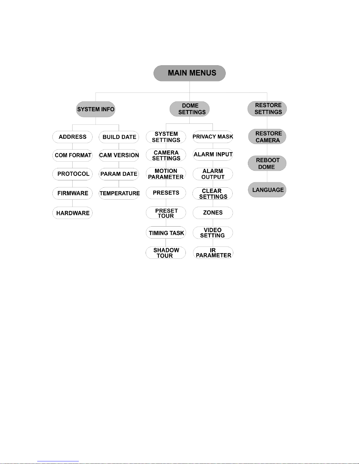
Menu tree
The menu tree of the TruVision 1080P HD-TVI PTZ domes is shown below.
Page 7

TruVision HD-TVI Series 4 PTZ Dome Camera Configuration Manual 5
Configuration
This section describes how to set up the menu settings.
System Info
Display the current system information of the PTZ dome, incl udi ng mod el,
address, protocol, etc.
Note:
Information on this menu cannot be edited.
The temperature refers to the internal temperature of the PTZ dome.
Dome Settings
System Settings
You can check and edit the system information of the software address, baud
rate, system time, etc. on the system information settings menu.
Note: Click the left and right directional button s in the PTZ control panel via the
web browser of the encoder to enter the next page and return to the previous
page of the submenu if more than one page is available.
Note: As TruVision recorders do not support an address greater than 255, a soft
address greater than 255 will not support any protocol even though the camera
supports 8190 for UTC-RS485 (Interlogix-Protocol) and 512 for DIGIPLEX and
ASCII. However, you can have an address greater than 255 for legacy products
that supports UTC-RS-485 (Interlogix-Protocol), DIGIPLEX or ASCII.
SOFT ADDRESS This is the address to connect and control the HD-TVI PTZ dome. It
can be used as an alternative to the hard address if, for example, the
address must be above the availab le hard addr es s.
SET SOFT
ADDRESS
ON: The soft address is the valid address for the HD-TVI PTZ dome.
The selectable soft address range is from 1 to 255.
OFF: This refers to the hard address. Use the DIP switch to set the
valid address for the HD-TVI PTZ dome.
SOFT BAUDRATE This is the valid baud rate for the HD-TVI PTZ dome with the soft
address.
Page 8

6 TruVision HD-TVI Series 4 PTZ Dome Camera Configuration Manual
SET SOFT BAUD ON: The soft baud rate is the valid baud rate for the HD-TVI PTZ
dome. Select 2400, 4800, 9600 or 19200.
OFF: Use the DIP switch to set the baud rate.
BROADCAST
ADDR
When set to ON, the control device with address 0 can control all
domes connected to it.
PELCO This is used for Pelco-P and Pelco-D protocols.
If the video
freezes, set PELCO to ON to improve the video quality.
SYSTEM TIME 1. Move the cursor to SYS TIME using the directional buttons
and click IRIS+ to enter.
2. Click the left/right directional buttons to position the cursor on
the specific item (year/month/day or hour/minute/second) of
which you want to change the value.
3. Click the up/down directional buttons to increase/decrease the
value.
4. Click IRIS+ button to confirm the settings and exit.
Y - M - D 12 12 12
H - M - S 15 33 25
DONE : OPEN
QUIT : CLOSE
ANGLE ZERO Define the angle zero of the PTZ dome.
Angle zero is when the PT position of the dome is 0,0. Use this
function to set the angle zero.
DISPLAY
SETTINGS
Enable or disable the on-screen display of PTZ movements, alarms,
time, presets, zone, address, error rate, and fan/heat show, etc.
DISPLAY SETTINGS
ZOOM RATIO ON
P/T ANGLE ON
ALARM
OFF
TIME
ON
PRESET
LABEL
ON
ZONE OFF
ADDRESS OFF
BACK EXIT
DISPLAY SETTINGS
ERROR RATE OFF
FAN/HEAT OFF
BACK EXIT
ZOOM RATIO ON: Enable the on screen display of zoom
ratio.
OFF: Disable the on screen display of zoom
ratio.
2: The ZOOM RATIO will display on screen for
2 seconds.
5: The ZOOM RATIO will display on screen for
5 seconds.
10: The ZOOM RATIO will display on screen
for 10 seconds.
Page 9

TruVision HD-TVI Series 4 PTZ Dome Camera Configuration Manual 7
P/T ANGLE ON: Enable the on screen display of P/T angle.
OFF: Disable the on screen display of P/T
angle.
2: The P/T angle will display on screen for 2
seconds.
5: The P/T angle will display on screen for 5
seconds.
10: The P/T angle will display on screen for 10
seconds.
ALARM ON: Enable the on screen display of alarm
message.
OFF: Disable the on screen display of alarm
message.
TIME ON: Enable the on screen display of zoom
ratio.
OFF: Disable the on screen display of zoom
ratio.
PRESET LABEL ON: Enable the on screen display of preset
label.
OFF: Disable the on screen display of preset
label.
2: The PRESET LABEL will display on screen
for 2 seconds.
5: The PRESET LABEL will display on screen
for 5 seconds.
10: The PRESET LABEL will display on screen
for 10 seconds.
ZONE ON: Enable the on screen display of zone.
OFF: Disable the on screen display of zone.
ADDRESS ON: Enable the on screen display of camera
address.
OFF: Disable the on screen display of camera
address.
ERROR RATE ON: Enable the on screen display of error rate.
OFF: Disable the on screen display of error
rate.
FAN/HEAT ON: Enable the on screen display of fan/heater
message.
OFF: Disable the on screen display of
fan/heater message.
HEAT CONTROL TEMP: The heater is controll ed b y the tem peratur e.
ON: Enable the heater.
OFF: Disable the heater.
N/A: Only for non-IR PT Z.
FAN CONTROL TEMP: The fan is controlled by the temperature.
ON: Enable the fan.
OFF: Disable the fan.
EIS SETTINGS ON: Enable the Electronic Image Stabilization.
OFF: Disable the Electronic Image Stabilization.
Page 10

8 TruVision HD-TVI Series 4 PTZ Dome Camera Configuration Manual
PRESET FOCUS ON: Enable the preset direct focus function to also record the focus
(F) value.
OFF: Disable the preset direct focus function.
PROTOCOL
ENABLE
ON: The user-defined protocol is enabled.
OFF: The user-defined protoc ol is disable d.
PROTOCOL Define the protocol: UTC RS-485, PELCO-P, PELCO-D, DIGIPLEX,
or ASCII.
485 CHECK Set to ON or AUTO for automatic RS-485 configuration diagnosis.
If the configuration is incorr ec t, an aler t will be recei ve d. If you set the
value as AUTO, it will automatically stop the diagnosis when no
errors exist.
MEMORY TIME The dome resumes its previous PTZ status when it restarts after a
power-off and had stopped at the position longer than the predefined
time. Set the memory time to 10s, 30s, 60s, 180s, or 300s.
NEAR FOCUS
LEVEL
This is a debug interface. It ranges from 0 to 2. Select one level to
have the optimal focus speed and accuracy depending on the actua l
scenario.
Camera Settings
You can set the camera parameters including focus, shutter speed, iris, etc.
CAMERA
GAIN LIMIT 15
DEFOG OFF
INIT LENS OFF
BACK EXIT
FOCUS Set the focus mode.
AF (Autofocus): The lens remains in focus during PTZ movements.
MF (Manual Focus): Manually adjust the focus using t he Focus+ and
Focus- buttons.
HAF (Half-autofocus): The PTZ dome only focuses automatically
once after panning, tilting and zooming.
Note: The focus mode needs to be changed to MF before controlling
Focus in the PTZ panel.
Page 11

TruVision HD-TVI Series 4 PTZ Dome Camera Configuration Manual 9
ZOOM LIMIT Set the user-defined limitation of the zoom amount. Zoom amount =
Optical zoom× Digital zoo m.
If you set the zoom limit to its minimum value (22), digital zoom is
disabled and optical zoom is at maximum value. If you set a lower
zoom limit, digital zoom is enabled.
ZOOM SPEED Define the speed at which the lens changes from wide to the optical
zoom.
SLOW SHUTTER This extends the exposure time under low light conditions in order to
obtain a clearer image. It can be set from 0 to 5 and the higher the
value is, the longer the exposure time.
DAY/NIGHT Set the value to AUTO, DAY or NIGHT.
AUTO: The PTZ dome automatically switches from Black and White
mode (NIGHT) and Color mode (DAY) depending on the light
conditions. This is default mode.
NIGHT (B/W): Switch the IR cut filter to Black and White mode to
increase the lens sensitivity in low light conditions
DAY (Color): Switch to Day mode in normal light conditions.
Note:
Set the DAY/NIGHT values in this menu. Call up preset 39 to set
the IR cut filter mode to DAY mode and call up preset 40 to set it
to NIGHT mode.
The DAY/NIGHT values cannot be configured unless the IR
function is disabled.
D/N LEVEL This is the light level for auto D/N mode switch.
The IR cut filter switches between DAY and NIGHT mode when the
light conditions reach this user-defined D/N sensitivity level.
SHARPNESS
This function increases the image gain and sharpens the edges in the
image to enhance image details.
Set the sharpness level between 0 and 15.
BLC/WDR Set the value as ON or OFF to enable or disable the functions.
EXP MODE AUTO: Auto iris, auto shutter and auto gain. The PTZ dome
automatically adjusts the values depending on the light conditions.
This is default mode.
IRIS: User-defined iris value, auto shutter and auto gain. It is the iris-
priority mode. Define the iris value in the IRIS, SHUTTER and GAIN
menus (see below).
SHUTTER: User-defined shutter speed, auto iris and auto gain. It is
the shutter-priority mode. Define the shutter speed in the IRIS,
SHUTTER and GAIN menus (see below).
MANUAL: User-defined iris, gain and shutter. in the IR I S, SHU TTER
and GAIN menus (see below).
IRIS It measures the amount of light entering to the lens. You can s et the
iris value from 0 to 17 in response to the changing light conditions.
The EXP MODE needs to be changed to MANUAL before controlling
the Iris in the PTZ panel.
Note: Iris is fully closed at 0 and fully open at 17.
SHUTTER The speed of the electronic shutter controls the amount of light
entering to the lens in a unit of time (a second). You can manually
configure the shutter speed for the PTZ dome. You can also enable a
slow shutter function for low light conditions.
The higher you set the SHUTTER value (a faster shutter speed), the
Page 12

10 TruVision HD-TVI Series 4 PTZ Dome Camera Configuration Manual
lower the amount of light entering per second, and the darker the
image. Set the value to 1, 2, 4, 8, 15, 30, 50, 125, 180, 250, 500,
1000, 2000, 4000 or 10000.
Note: The value of X indicates that the shutter speed is 1/X second.
GAIN Gain value: The gain value is the amplification degree of the original
image signal. Set the value between 0 and 15.
Gain limit: The higher gain value set, the more noise will appear in
the image. You can set the maximum gain value between 0 and 15 to
limit the gain range and control the noise in the image.
Note: Change DAY/NIGHT mode to DAY or NIGHT mode, and set
the EXP MODE as MANUAL before adjusting the gain value.
EXPOSURE COMP Adjust this value to increase the brightness of the image.
Set the EXPOSURE COMP value between 0 and 14. Default value is
7.
WB MODE Set the WHITE BALANCE MODE as AUTO, INDOOR, OUTDOOR,
SELFDEF (self-defined), ATW (auto-tracking) or HAUTO (half-auto).
AUTO: The dome automatically retains color balance according to
the current color temperature.
INDOOR, OUTDOOR: These two modes are for indoor use and
outdoor use respectively.
SELFDEF: Adjust the color temperature manually.
Note: In SELFDEF mode, you need to adjust the RED and BLUE
values manually.
ATW: In aut o-tracking mode, white balance is continuously being
adjusted in real-time according to the color temperature of the scene
illumination.
HAUTO: Select this mode so that the viewed image automatically
retains color balance depending on the current color temperature.
RED It is used to adjust the red value when choosing SELFDEF for
WHITE BALANCE and it can be set from 0 to 255.
BLUE It is used to adjust the blue value when choosing SELFDEF for
WHITE BALANCE and it can be set from 0 to 255.
IMAGE FLIP When enabled, the image is flipped diagonally along its central axis
to obtain a mirror reflection of the image.
FOCUS LIMIT Set the minimum focus distance.
Configure the focus limit at a longer distance when the target is far
away to avoid the PTZ dome focusing on objects close to it, or
configure a shorter distance when the target is close to the PTZ
dome so it does not focus on further away objects.
Set FOCUS LIMIT to 1cm, 30cm, 1m, 3m, 5m or AUTO to make sure
that the PTZ dome focuses on the target.
Note: If you test the PTZ indoors the camera may not focus when
zooming at high ratio. Please adjust this parameter to a lower value.
2D DNR ON: The larger the value, the less the noise there will be in low light
conditions.
OFF: Disable the function.
3D DNR ON: The larger the value, the less the noise there will be in low light
conditions.
OFF: Disable the function.
MINI ZOOM LIMIT Set the minimum zoom of the lens.
Page 13

TruVision HD-TVI Series 4 PTZ Dome Camera Configuration Manual 11
Note: This function is not supported by all PTZ dome cameras.
CHROMA
SUPPRESS
ON: Suppress color noise to obtain clear and high-quality images in
low light conditions.
OFF: Disable the function.
SATURATION Saturation indicates the brightness of the color. The higher the
saturation, the brighter the color.
CONTRAST Contrast is the degree of difference between the darker and lighter
parts of the image.
SCENE MODE Select the scene mode as INDOOR or OUTDOOR. The default
image settings change d ep end ing on the selected scene mode.
HLC Use this highlight compensation function to compensate for areas
with strong spots of light in order to produce clearer images.
Set the value to brighten the darker area and weaken the highlight
area of the image. The larger the value selected, the stronger the
effect.
SHARPNESS
COMP
Set the value to automatically adjust the sharpness of the image to
get a clear image. The larger the value selected, the stronger the
effect.
GAIN LIMIT The higher gain value you set, the more noise will appear in the
image. Set the maximum gain value between 0 and 15 to limit the
gain range and control the noise in the image.
DEFOG Enable this function to improve an image’s visibility and clarity in
foggy weather.
INIT LENS Enable this function to automatically initialize the lens to ensure
normal operation.
Motion Parameter
AUTO FLIP In manual tracking mode, the dome automatically rotates 180
degrees horizontally when a target object passes directly under the
PTZ dome for uninterrupted tracking.
Note: AUTO-FLIP is set to ON by default. It is not user-definable.
PROPORTIONAL
PAN
Use this function to change the pan/tilt speed according to the
amount of zoom. When there is a large amount of zoom, the pan/tilt
speed will be slower to prevent the image from moving too quickly in
live view.
Set to ON or OFF to enable/disable the function.
Note: This function is enabled automatically while setting a shadow
tour.
Page 14

12 TruVision HD-TVI Series 4 PTZ Dome Camera Configuration Manual
PARK TIME This is a period of inactivity after which the PTZ dome automatically
starts a predefined action. Set it between 5 and 720 seconds.
PARK This is a predefined action. It can be set as presets 1-8, shadow tours
1-5, preset tours1-10, pan scan, tilt scan, panoramic scan, day mode,
night mode or none.
Note: If no control signal is received after the park time under the
following situations, no park action is performed:
- When performing dome actions by calling special presets; or,
- When performing external alarm linkage actions.
SCAN SPEED The scan speed defines the scan degree per second of pan scan, tilt
scan, and panoramic scan.
Select a scan speed between 1 and 40. The larger the value, the
faster the scan speed.
IMAGE FREEZE Use this feature to directly switch from live view of the current scene
to another scene that is defined by a preset without showing the
areas between these two scenes. It reduces the bandwidth usage in
a digital network system and also provides privacy protection for the
areas between the two scenes displayed.
DOME SPEED Manually set the dome speed between 1 and 10.
PRESET SPEED Set the speed to call up a preset between1 and 8. The larger the
value, the faster the speed to call up a preset.
ENABLE LIMIT These are user-configurable positions that limit the panning and tilting
area of the PTZ dome. Set the left, right, up and down limits to define
an area.
ON: This feature is enabled.
OFF: This feature is disabled.
LIMIT SETTINGS Set prompts to set the left, right, up and do wn lim its from the menu.
CLEAR LIMITS Clear the limit setting.
SET ELEVATION ON: Enable to increase the elevation angle range of the PTZ dome.
OFF: Disable the function.
Note: The range of the elevation angle is 0 to 90° by default. It
changes to between -15° and 90° when SET ELEVATION is enabled.
Presets
A preset is a user-defined monitoring position/point. You can call up the preset
number to change the current monitor scene to the defined position.
PRESET NO. Select the preset number from between 1 and 256.
<UNDEFINED> This is the preset label.
Page 15

TruVision HD-TVI Series 4 PTZ Dome Camera Configuration Manual 13
If the preset has been defined, the preset label is displayed under the
number. If it has not been defined, UNDEFINED is displayed under
the number.
SET PRESET Set the desired scene/position of the preset.
CLEAR Clear the preset settings.
Preset Tour
A sequence of user-defined presets stored in the system memory and recalled
when required, either upon an alar m tr i g g er , when prog r am med, or o n manual
recall.
PRESET TOUR
NO.
Select a preset tour number between 1 and 10.
EDIT PRESET
TOUR
Enter edit mode. The menu is shown below.
Click the left/right direc t ion al buttons to position the cursor in the
PRESET, DWELL and SPD columns.
Click the up/down directional buttons to set the value of the preset
number, dwell time and patrol speed.
NUM PST DWELL SPD
1 0 6 30
2 0 6 30
3 0 6 30
4 0 6 30
5 0 6 30
6 0 6 30
7 0 6 30
DONE : OPEN QUIT : CLOSE
Note: The presets used in a patrol must be pre-defined. The dwell
time is a preset amount of time a camera image is displayed before
the camera moves to the next preset position. It is the camera's
inactive time. Select a dwell time value between 0 to 800 seconds,
which is divided into 30 levels . The patrol speed is the scanning
speed the PTZ dome to switch between the presets. Select a patrol
speed value between1 and 40.
PREVIEW Preview the current patrol.
Page 16

14 TruVision HD-TVI Series 4 PTZ Dome Camera Configuration Manual
CLEAR PRESET
TOUR
Delete the current patrol.
PRESET TOUR-D This is the time to switch from one preset to another. Select 5 s, 10 s,
20 s, 30 s, or 60 s.
Timing Task
A timing task is a preconfigured action that can be performed automatically at a
specific date and time.
TASK NO. Select a task number between 1 and 8.
ENABLE TASK ON: Enable the task.
OFF: Disable the task.
ACTION Select a task from preset 1 to 8, shadow tour 1 to 5, preset your 1 to
10, pan scan, tilt scan, panoramic scan, day mode, night mode, zero
calibrate and none.
TASK TIME Click the left and right directional buttons to position the cursor at
WEEK, START (H-M) and END (H-M).
Click the up and down directional buttons to set the start and end
times to run the time task.
WEEK WHOLE WEEK
START(H-M) 00 00
END(H-M) 00 00
DONE : OPEN
QUIT : CLOSE
Note: The weekday can be set to be from Monday to Sunday or
Whole Week; H refers to Hour and M refers to Minute.
TASK PREVIEW Preview the current task.
TASK CLEAR Delete all the defined tasks.
Page 17

TruVision HD-TVI Series 4 PTZ Dome Camera Configuration Manual 15
Shadow Tour
A shadow tour is a recording of a user-defined movement of a PTZ dom e
camera. A shadow tour can be stored and replayed.
SHADOW TOUR
NO.
Select a shadow tour number between 1 and 5.
EDIT SHADOW
TOUR
Use this menu to record a shadow tour.
Click the PTZ control and directional buttons to operate the PTZ
dome to draw a path, including pan scan, tilt scan, zoom in, zoom
out, etc. The PTZ dome automatically memorizes the path as a
shadow tour.
REMAIN MEMORY 100
DONE : OPEN
QUIT : CLOSE
Note: The pan/tilt movements and the lens operations cannot be
simultaneously memorized.
PREVIEW Preview the current shadow tour.
CLEAR SHADOW
TOUR
Delete all the defined shadow tours.
REMAINING This shows the remaining memory of the PTZ dome to configure
shadow tours. When it reaches 0, no more shadow tours can be
configured.
Privacy Mask
This is a visual block or masked area that is configured to conceal the view in
designated areas. For example, blocking out neighboring windows to protect
them from being viewed and/or recorded.
The masked areas can move with the pan/tilt movements and automatically
adjust in size as the lens zooms in and out.
Page 18

16 TruVision HD-TVI Series 4 PTZ Dome Camera Configuration Manual
Note: Occasionally portions of the masked area may be visible when quick pantilt-zoom commands are executed. It is recommended that privacy mask regions
are configured to extend past the boundaries of the protected area to avoid
inadvertent exposure.
MASK NO. The privacy mask number, which ranges from 1 to 24.
MASK STATU S ON: Enable the privacy mask function.
OFF: Disable the privacy mask function.
SET MASK Click this menu option to enter the editing mode (see below).
ADJUST MASK POS
FOCUS SHIFT STATUS
SAVE : OPEN
QUIT : CLOSE
ADJUST MASK POS: Use this function to position the mask on
screen. Click the directional buttons to move the privacy mask to the
desired area. Click the FOCUS+ button to call up the ADJUST MASK
SIZE message on screen. Click the up/down buttons to
increase/decrease the height of the mask and click right/left buttons
to increase/decrease the width of the mask.
Note: The tilt range to configure privacy masks is between 0° and
70°.
SAVE: Click to save changes and return to the previous menu. The
masked area turns gray. To modify the mask, click IRIS+ to enter the
SET MASK menu. Click IRIS+ button again to edit.
QUIT: Cancel.
CLEAR MASK Delete all privacy masks.
Alarm Input
You can configure the PTZ dome to respond to alarm events with alarm linked
actions, such as calling presets, preset tours, shadow tours, scanning, etc.
Page 19

TruVision HD-TVI Series 4 PTZ Dome Camera Configuration Manual 17
ALARM INPUT
RESUME ON
SEQUENCE 5
DELAY TIME 5
ALARM SETTING
BACK EXIT
RESUME ON: Enable the PTZ dome to resume its previous activity after the
triggered actions finished.
OFF: Disable the PTZ dome to resume its previous activity after the
triggered actions finished.
Note:
If the PTZ dome is moving when a linkage action is triggered, it
will stop at the current position and resume from this position
after the linkage action finishes.
The PTZ dome can be configured to resume the PTZ positions,
focus and iris value.
SEQUENCE This is a user-defined interval after which the PTZ dome will respond
to one alarm first and then to the next one when more than one
alarm of the same priority occurs at the same time. Set a value
between 1 and 200 seconds.
DELAY TIME If a linkage action has already been triggered by an alarm input, the
PTZ dome only responds to the input from the same channel after a
user-defined reset delay time.
This is the rest time that the PTZ dome considers an alarm to be
active when it is physically cleared. Set a value between 0 and 300
seconds.
ALARM
SETTING
ALARM NO.: The alarm number up to 2.
PRIORITY: Set it as HIGH, MEDIUM or LOW. If multiple alarms with
different priorities are triggered at the same time, the dome only
responds to the alarm with the highest priority. If multiple alarms with
the same priority are triggered at the same time, then the dome will
respond to each alarm according to the defined alarm sequence.
LINK: It can be set as preset from 1 to 8, shadow tour from 1 to 5,
preset tour from 1 to 10, panning scan, tilting scan, panoramic scan,
day mode, night mode or none when an alarm occurs.
ALARM OUTPUT: Choose NONE to disable alarm outputs or
choose 1 to active ALARM OUTPUT 1.
Note: There is 1 alarm output configurable; configuring the alarm
output 2 will be invalid.
ALARM INPUT: Set the input status to OPEN (Normally open),
CLOSE (Normally closed) or OFF (disable the alarm input).
Note: If you set the status as OPEN, the alarm will be triggered by
high current level. If you set the status as CLOSE, the alarm will be
triggered by low current level. If you set the status as OFF, it will be
triggered when this input channel is disabled.
Page 20

18 TruVision HD-TVI Series 4 PTZ Dome Camera Configuration Manual
ALARM SETTING
ALARM NO. 1
PRIORITY HIGH
LINK NONE
ALARM OUTPUT NONE
ALARM INPUT OPEN
BACK EXIT
Alarm Output
An alarm output is a configurable alarm output interface on the PTZ dome back
box which can connect and trigger another alarm device to operate.
ALARM OUTPUT Set the alarm output type as OPEN (normally
open) or CLOSE (normally closed).
Note: Only one alarm output c an be configured.
The second alarm output cannot be configured.
OUTPUT1, OUTPUT2 OPEN: Set the alarm output to normally open.
CLOSE: Set the alarm output to normally closed.
DWELL TIME This is the duration of the alarm output signal. Set
the value between 0 and 60 seconds.
Clear Settings
PRESETS
Clear all the settings of presets.
PRESET TOURS Clear all the settings of preset tours
SHADOW
TOURS
Clear all the settings of shadow tours
MASKS Clear all the settings of masks.
ZONES Clear all the settings of zones.
TIME TASKS Clear all the settings of timing tasks.
Zones
A zone is a panning and tilting area defined by left/right limits. You can configure
the zones in the ZONES submenu. Define a zone when the targeted surveillance
scene is limited.
Page 21

TruVision HD-TVI Series 4 PTZ Dome Camera Configuration Manual 19
ZONE NO. Select a zone number ranging between 1 and 8.
<UNDEFINED> This is the zone label.
If the zone has been defined, the zone label is displayed
under the number. If it has not been defined,
UNDEFINED is displayed under the number.
EDIT ZONE Follow the prompts to set the left and right limits.
ZONE STATUS This shows the current status of the zone.
SCAN STATUS ON: Enable zone scanning.
OFF: Disable zone scanning.
CLEAR ZONE Clear the zone settings.
Video Setting
Modify the video output standard, including resolution and frame rate, as desired.
IR Parameter
You can configure the IR parameters including the IR sensitivity, N/M LED
current as well as LED control, etc.
Note: The IR parameter settings are supported by IR PTZ domes only.
IR PARAMETER
IR SENSITIVITY MEDIUM
N/M LED CURRENT 8
FAR LED CURRENT 8
REFERENCE ZOOM 2
LED CONTROL AUTO
SWITCH DELAY(S) 2
SMART IR 0
BACK EXIT
IR SENSITIVITY Set the sensitivity of the IR LED to HIGH, MEDIUM or LOW.
N/M LED
CURRENT
Select the current of the near/middle IR LED from between 1 to 10.
FAR LED
CURRENT
Select the current of the far IR LED from between 1 to 10.
REFERENCE
ZOOM
When the actual zoom rate is greater than the zoom limit, the IR
switches to long-distance IR LED.
Page 22

20 TruVision HD-TVI Series 4 PTZ Dome Camera Configuration Manual
When the zoom rate is less than the zoom limit, the IR switches to
the near/medium-distance IR LED.
LED CONTROL Set the LED control. Select one of the options:
ALL ON: Enable all IR LEDs
FAR ON: Enable long-distance IR LEDs
NEAR ON: Enable near/medium -distance IR LEDs
AUTO: Enable IR LED automatically depending on the light
conditions
ICR: Adjust the IR LED working mode according to the ICR (infrared
cut filter)
CLOSE: Disable IR LEDs
SWITCH DELAY(S) This is the time delay in switching between long-distance IR LED and
N/M-distance IR LED.
SMART IR This function is implemented to decrease the over exposure of IR
light and it can be set from 0 to 15. The higher the value is, the higher
suppress level of IR o ver e x posur e.
Restore Camera
Enter MAIN MENU > RESTORE CAMERA
Click IRIS+ to restore the camera settings to the default value, or click IRIS- to
exit.
Note: Camera settings include the image parameters, lens settings and display
settings.
Restore Settings
You can reset all dome settings to factory default parameters.
Note: Dome settings are mainly of PTZ parameters and alarm parameters. They
also include some system settings, such as the dome address.
Enter default dome setti ng s menu: MAIN MENUS > RESTORE DEFAULTS
Click IRIS+ to restore the dome settings to the default value or click IRIS- to exit.
Reboot Dome
Enter MAIN MENU > REBOOT DOME. Click IRIS+ to reboot the PTZ dome
remotely.
Language
Enter MAIN MENU > LANGUAGE. Click left or right to change the language and
click IRIS+ to confirm the language.
 Loading...