

Page 1

Model 610 Barium Ferrite
Touch Card Reader
Installation Guide
Security Products by GE are now part of the UTC Fire & Security family
P/N 460094400D • ISS 09NOV10
Page 2
Copyright © 2010 UTC Fire & Security. All Rights Reserved.
r
r
This document may not be copied in whole or in part or otherwise reproduced without prior
written consent from UTC Fire & Security, except where specifically permitted under US
and international copyright law.
Disclaime
Trademarks and patents GE and the GE monogram are trademarks of the General Electric Company and are under
Intended use Use this product only for the purpose it was designed for; refer to the data sheet and user
FCC compliance This equipment has been tested and found to comply with the limits for a Class A digital
Certification and compliance
The information in this document is subject to change without notice. UTC Fire & Security
assumes no responsibility for inaccuracies or omissions and specifically disclaims any
liabilities, losses, or risks, personal or otherwise, incurred as a consequence, directly or
indirectly, of the use or application of any of the contents of this document. For the latest
documentation, contact your local supplier or visit us online at utcfireandsecurity.com.
This publication may contain examples of screen captures and reports used in daily
operations. Examples may include fictitious names of individuals and companies. Any
similarity to names and addresses of actual businesses or persons is entirely coincidental.
license to UTC Fire & Security. Secure Perfect is a registered trademark of UTC Fire &
Security. Picture Perfect is a trademark of UTC Fire & Security.
Other trade names used in this document may be trademarks or registered trademarks of
the manufacturers or vendors of the respective products.
documentation for details. For the latest product information, contact your local supplier or
visit us online at www.utcfireandsecurity.com.
device, pursuant to part 15 of the FCC Rules. These limits are designed to provide
reasonable protection against harmful interference when the equipment is operated in a
commercial environment. This equipment generates, uses, and can radiate radio frequency
energy and, if not installed and used in accordance with the instruction manual, may cause
harmful interference to radio communications.
You are cautioned that any changes or modifications not expressly approved by the party
responsible for compliance could void the user's authority to operate the equipment.
2002/96/EC (WEEE directive): Products marked with this symbol cannot be disposed of as
unsorted municipal waste in the European Union. For proper recycling, return this product
to your local supplier upon the purchase of equivalent new equipment, or dispose of it at
designated collection points. For more information see: www.recyclethis.info.
Manufacture
Contact information For contact information, see our Web site: www.utcfireandsecurity.com.
UTC Fire & Security
HQ and regulatory responsibility:
UTC Fire & Security, 9 Farm Springs Road, Farmington, CT 06034-4065, USA
WARNING: This is a Class A product. In a domestic environment, this product may cause
radio interference; in which case, the user may be required to take adequate measures.
Page 3

Content
Introduction 1
Product features 1
Installation overview 1
Mounting the reader 2
Connecting the reader 7
Adapting the Micro/4 or Micro/2 for the Model 610 reader 19
Testing the reader 20
Technical specifications 21
Functional specifications 22
Contacting technical support 23
Model 610 Bariu
m Ferrite Touch Card Reader Installation Guide i
Page 4

Page 5

Introduction
This manual is an installation guide for the Model 610 Barium Ferrite (BaFe)
Touch Card Reader.
The Model 610 is a single-stage reader. It operates with a standard BaFe card
and produces a Wiegand output that is forwarded to its microcontroller for
processing. This reader operates with Picture PerfectTM and Secure Perfect®
products. For keypad operation, the Model 610 Reader works in conjunction with
the Model 651 keypad. The reader can be located up to 1,000 feet (304.8
meters) from the microcontroller using Belden 8725 cable.
The Model 610 Reader is supplied with a mounting bracket and gasket which
attaches to the surface of the wall with four screws. The reader is then secured to
the bracket with a flange and one screw. No gang box is required. An optional
mounting kit is available for solid wall mounting.
Product features
The UTC Fire & Security Model 610 BaFe Touch Card Reader offers:
• Sturdy beige molded plastic cover mounted flush to wall surface.
• Slotless design protects the unit against tampering and harsh environments.
• Bicolor: LED changes from red to green indicating valid read.
Installation overview
The following is a recommended sequence of steps for installing and setting up
the reader.
1. Install the reader mounting. See “Mounting the reader” on page 2.
Connect the reader. See “Connecting the reader” on page 7.
2.
3. Mount the reader. See “Mounting the reader” on page 2.
4. Test the reader. See “Testing the reader” on page 20.
Model 610 Bariu
m Ferrite Touch Card Reader Installation Guide 1
Page 6

Mounting the reader
The mounting requirements for the Model 610 BaFe Touch Card Reader are as
follows:
• No assembly is required. Remove mounting plate from back of reader. Attach
grounding screw to proper earth ground.
• The Model 610 can be mounted on any hollow wall with the mounting plate
that has been included in the assembly kit. It can also be mounted with a
user-supplied gang box, or on a solid wall with a back box. In either case, a
gasket is supplied with the reader to form a seal between the mounting plate
of the reader and the mounting surface. See applicable wiring diagram for
wiring instructions. Ensure reader is mounted within 1000 feet of the
microcontroller (with or without the amplifier card or door junction box), then
refer to the “Connecting the reader” section for detailed instructions.
There are three different methods for mounting the reader:
• Surface mount to interior/exterior single-gang electrical box:
Refer to Figure 1 on page 3 and Figure 2 on page 4.
1. Press plate with gasket against wall and secure with two (2) each #6-32
screws.
2. Refer to Figure 5 on page 8 through Figure 10 on page 18 for wiring
instructions.
3. Place Model 610 housing against mounting plate, top edge first, centering
housing on retaining tables. Secure housing to plate at bottom with one (1)
each #6-32 x 3/8-inch security screw provided or equivalent. Use security
wrench P/N 380486001.
• Surface mount to interior/exterior surface without single-gang electrical
box:
Refer to Figure 1 on page 3 and Figure 3 on page 5.
Secure the mounting plate with gasket to wall using appropriate fasteners.
1.
Use at least four of the six holes provided.
2. Refer to Figure 5 on page 8 through Figure 10 on page 18 for wiring
instructions.
3. Place the Model 610 housing against mounting plate, top edge first,
centering housing on retaining tabs. Secure housing to plate at bottom
with one (1) #6-32 x 1/4-inch security screw provided or equivalent. Use
security wrench P/N 380486001.
2
Model 610 Barium Ferrite Touch Card Reader Installation Guide
Page 7
• Solid wall mount with back box:
Refer to Figure 1 below and Figure 4 on page 6.
1. Select and cut appropriate opening for conduit access using a hole saw.
2. Install conduit gland assembly.
3. Install conduit and route wires to inside of box.
4. Mount reader mounting plate installed with gasket to back box cover with
four (4) #6-32 screws. Secure mounting plate with four (4) #6 lock
washers and four (4) #6-32 nuts on the far side of the mounting plate to
retain cover and plate assembly.
5. Feed wires from back side of reader through the hole provided on the
center of the cover.
6. Secure reader to back box cover using two (2) tabs on the mounting
bracket and one (1) #6-32 screw.
7. Refer to Figure 5 on page 8 through Figure 10 on page 18 for wiring
instructions.
Figure 1: Mounting Diagram for the Model 610 BaFe Touch Card Reader
Model 610 Bariu
m Ferrite Touch Card Reader Installation Guide 3
Page 8
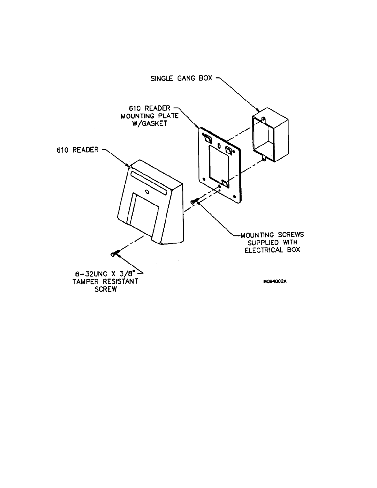
Figure 2: Model 610 BaFe Touch Card Reader Surface Mounted with Interior or Exterior
Single-Gang Electrical Box
4
Model 610 Barium Ferrite Touch Card Reader Installation Guide
Page 9
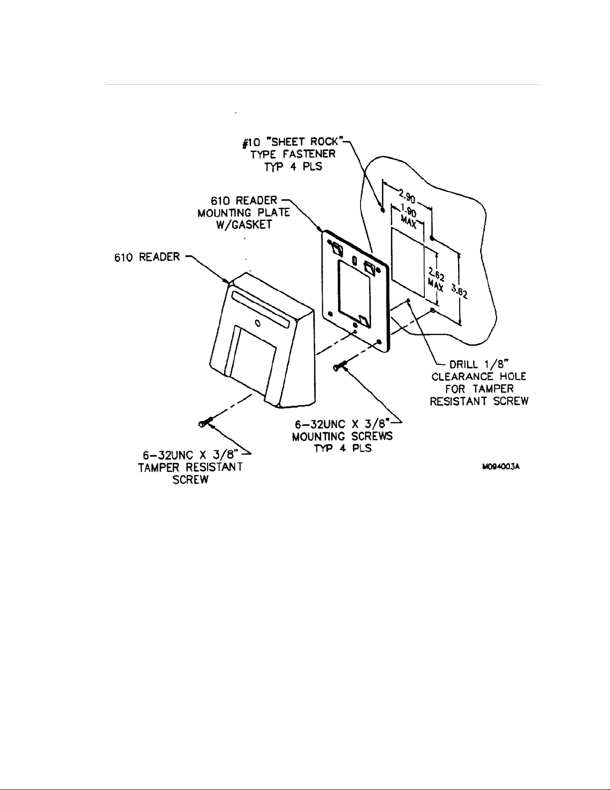
Figure 3: Model 610 BaFe Touch Card Reader Surface Mounted without Single-Gang
Electrical Box
Model 610 Bariu
m Ferrite Touch Card Reader Installation Guide 5
Page 10

Figure 4: Model 610 BaFe Touch Card Reader Surface Mounted with Solid Wall Mounting
Kit
6
Model 610 Barium Ferrite Touch Card Reader Installation Guide
Page 11

Connecting the reader
The following diodes (IN4004) are required:
1. Each door strike requires one diode if DC powered.
2. Each customer-supplied relay that activates the door strike requires one diode.
• One general-purpose 12V relay with 180-ohm (or greater) coil is required
for each door strike installed with customer-supplied power supply for the
door strike.
• When using a back box kit for solid-wall mounting, a hole saw is required
for cutting conduit access.
To wire this reader to a:
• Micro/5 2RP or 2SRP board, refer to Figure 5 on page 8.
Note: It is not necessary to use an amp card or door junction box with
the Micro/5.
• Micro/2 8RP or Micro/4 8RP board, refer to Figure 6 on page 10.
• Micro/4 or Micro/2 with an amp card, refer to Figure 7 on page 12.
• Micro/4 or Micro/2 with a door junction box, refer to Figure 8 on page 14 and
Figure 9 on page 16.
• Model 651 Keypad, refer to Figure 10 on page 18, then refer to the
appropriate figure listed above.
Model 610 Bariu
m Ferrite Touch Card Reader Installation Guide 7
Page 12

Figure 5: Model 610 BaFe Touch Card Reader Installed Directly to the Micro/5
8
Model 610 Barium Ferrite Touch Card Reader Installation Guide
Page 13

Notes (unless otherwise specified):
1. Shielded cable is recommended in electrically noisy environments.
2. If using shielded cable, connect all shields together at the microcontroller end.
Connect to ground stud in the lower left connect of Micro/2/4/5 cabinets using
14-AWG wire. No shield connections required at the reader.
3. If using a local power supply, do not connect +12V line from the
microcontroller to the reader. However, the negative side of the power supply
must be connected to the microcontroller (pin 2 on the reader port). Keep the
wiring from power supply to reader less than 50 feet.
4. Switching the external indicator drives to GND activates the indicator. High
impedance or +12V de-activates indicators. These drives may also be
connected to user supplied, external indicating circuitry.
5. Refer to the appropriate system manual to determine whether this connection
is required for door switch operation.
6. Blocking diodes may be 1N4002, 1N4003, or 1N4004 (installer supplied) for
the door strike assembly.
7. Protection diodes may be 1N4148 or similar, installer supplied, and located in
a secure area.
8. Fuse, power supply, door strike, and relay are provided by the installer.
Model 610 Bariu
m Ferrite Touch Card Reader Installation Guide 9
Page 14

Figure 6: Model 610 BaFe Touch Card Reader Installed Directly to Micro/2 or Micro/4
10
Model 610 Barium Ferrite Touch Card Reader Installation Guide
Page 15

Notes (unless otherwise specified):
1. Protection diodes may be 1N4002, 1N4003, or 1N4004 for the door strike
assembly (supplied by the installer). Use for DC strikes only.
2. One amp fuse (supplied by the installer).
3. Power supply (fused primary) and relay provided by the installer/customer.
4. Relay coil resistance must be 180 ohms or greater at 12 VDC.
5. Use Belden cable 8725 or equivalent.
6. Reader must be mounted within 1000 feet of the microcontroller.
Model 610 Bariu
m Ferrite Touch Card Reader Installation Guide 11
Page 16

Figure 7: Model 610 BaFe Touch Card Reader Installed with Amplifier Card
12
Model 610 Barium Ferrite Touch Card Reader Installation Guide
Page 17

Notes (unless otherwise specified):
1. Protection diodes may be 1N4002, 1N4003, or 1N4004 for the door strike
assembly (supplied by the installer). Use for DC strikes only.
2. One amp fuse (supplied by the installer).
3. Power supply (fused primary) and relay provided by the installer/customer.
4. Use Belden cable 8725 or equivalent.
Model 610 Bariu
m Ferrite Touch Card Reader Installation Guide 13
Page 18

Figure 8: Model 610 BaFe Touch Card Reader Installed with Door Junction Box
14
Model 610 Barium Ferrite Touch Card Reader Installation Guide
Page 19

Notes (unless otherwise specified):
1. Use Belden cable 8725 or equivalent.
2. Reader must be mounted within 1000 feet of the microcontroller.
3. See next figure for wiring details on Type I and Type II junction boxes.
Model 610 Bariu
m Ferrite Touch Card Reader Installation Guide 15
Page 20

Figure 9: Wiring for Type I and Type II Junction Boxes
16
Model 610 Barium Ferrite Touch Card Reader Installation Guide
Page 21

Notes (unless otherwise specified):
1. Pin outs for J1, J2, and J3 are identical for both Type I and Type II junction
boxes (J-boxes).
2. J1A, J2A, and J3A are used in dual junction box applications and have
identical pin outs to J1, J2, and J3.
3. Switch settings (SW1) for both Type I and Type II junction boxes are
identical (see drawing No. 530018002, junction box switch and jumper
settings).
4. AC power in, pin outs are NOT the same,
Model 610 Bariu
m Ferrite Touch Card Reader Installation Guide 17
Page 22

Figure 10: Model 610 BaFe Touch Card Reader Installed with Model 651 Keypad
Tie the wire from the Model 651 keypad to the corresponding wire on the Model
610. For example, tie the keypad 12 VDC line to the Model 650 12 VDC line.
Then refer to the appropriate wiring diagram.
18
Model 610 Barium Ferrite Touch Card Reader Installation Guide
Page 23

Adapting the Micro/4 or Micro/2 for the Model 610 reader
These microcontrollers require the UTC Fire & Security Universal EPROM in
place of the standard EPROMs. Check to insure that the microcontroller contains
the appropriate EPROM.
Model 610 Bariu
m Ferrite Touch Card Reader Installation Guide 19
Page 24

Testing the reader
Follow the steps below to verify that the reader is working correctly.
1. Verify all communication lines with a multimeter by testing voltage levels at
the reader. Using ground as a reference, the power and data lines should
measure 7 to 12 volts, and the door DO should measure approximately 4.5
volts.
2. Check all cabling and electrical connections from the reader to the
microcontroller. If applicable, also check the cabling and electrical
connections between the optional amplifier card/door junction box and the
Model 651 Keypad to the microcontroller.
3. Verify that the microcontroller is properly configured. For the Micro/5, ensure
that the proper version of the firmware is installed. For the Micro/2 and
Micro/4, ensure that the correct EPROM is installed. Refer to your
microcontroller manual.
4. Verify proper reader operation.
• Select a test card with a known format and data. If the reader is used with
a Model 651 Keypad, assign a four-digit Personal Identification Number
(PIN).
• Place the card face down on the faceplate of the reader.
• If used with a Model 651 Keypad, when yellow PIN LED lights, enter PIN
badge code (+key, four-digit PIN, x key) after each beep tone.
• Observe the LED; green indicates a valid access.
• Open door.
5. Verify proper host system operation. Refer to your host system manual for
operation details.
6. Check the other installed readers.
7. Repeat this test procedure with each installed Model 610 Reader.
20
Model 610 Barium Ferrite Touch Card Reader Installation Guide
Page 25

Technical specifications
Operating Temperature Range: -22 to 158°F (-30 to 70°C)
Humidity Range: 0% to 90%, noncondensing
Physical Dimensions: 4.60 in (H) x 4.00 in (W) x 2.25 in (D)
11.68 cm (H) x 10.16 cm (W) x 5.72 (D)
Parts List:
• Model 610 BaFe Touch Card Reader
• Universal EPROM for Microcontroller
• Label, Model 610 Reader
• Door Junction Box, Single, 12 VDC
• Amplifier Card, Wiegand
• Model 651 Environmental Keypad
• Gasket
• Cable Gland
• Back Box Mounting Kit
• Reader Wrench
Maximum Cabling Distance: 1000 feet from reader to microcontroller
Power Requirements: 12 VDC 10%, 130 mA (typical) @ reader
Color: Beige
Data Signal: Pulse width - 100 microseconds, pulse to pulse = 1 ms
Model 610 Bariu
m Ferrite Touch Card Reader Installation Guide 21
Page 26

Functional specifications
Product Operation: Hall-effect devices within the reader detect patterns of
magnetic dots on a BaFe card placed face down, flush to metal read plate. The
UTC Fire & Security system database then converts these patterns to binary
numbers and verifies access authority.
Application: Intended for areas requiring a moderately high level of security for
controlled access. Can be combined with a Model 651 Keypad for PIN operation.
Compatibility: Interfaces to existing UTC Fire & Security systems using the
universal EPROM required for each Micro/2 or Micro/4 microcontroller and the
Micro/5 flash memory system. The Micro/2 and Micro/4 microcontrollers use the
Universal EPROM.
Reader Technology Type: BaFe input with Wiegand data format output.
Badge Format: Badge format 3201.
Mounting: Mounted flush to the wall using a metal backplate (supplied with
reader). See the section on hardware installation for detailed instructions. The
ground screw on the backing plate must be connected to a good earth ground
(not power supply ground). Maximum distance to microcontroller is 1000 feet.
When installed with a Model 651 Keypad, reader must be installed immediately
adjacent to keypad.
Appearance: Sturdy beige molded plastic cover.
Indicators: Red and green LED indicators are provided.
• Red LED: Normally on when power is applied to the reader.
• Green LED: Indicates a valid badge read.
22
Model 610 Barium Ferrite Touch Card Reader Installation Guide
Page 27

Contacting technical support
For assistance installing, operating, maintaining, and troubleshooting this
product, refer to this document and any other documentation provided. If you still
have questions, you may contact presales and technical support.
Note: Be ready at the equipment before calling for technical support.
You can reach technical support by phone 8 a.m. to 7 pm. EST, Monday through
Friday.
North America:
888-437-3287
Asia
T 852-2907-8108
F 852-2142-5063
Australia
T 61-3-9239-1200
F 61-3-9239-1299
Canada
T 800-267-6317
F 613-737-5517
Europe
T 32-2-725-11-20
F 32-2-721-40-47
Latin America
T 561-998-6100
F 561-994-6572
utcfireandsecurity.com
© 2010 UTC Fire & Security. All Rights Reserved.
GE and the GE monogram are trademarks of the General Electric Company and
are under license to UTC Fire & Security, 9 Farm Springs Road, Farmington, CT
06034-4065.
Model 610 Bariu
m Ferrite Touch Card Reader Installation Guide 23
Page 28

24 Model 610 Barium Ferrite Touch Card Reader Installation Guide
 Loading...