

Page 1
GE
Security
Single Channel Contact-Closure Transmission
Models 251D and 2251D
installation instructions
11-0251-030212-A
Page 2
251D and 2251D
GENERAL
The GE Security Series 251D single channel contact-closure system transmits switch/status
information or control signals. A system consists of a transmitter (part number 251D-T) and receiver
(part number 251D-R). Throughout these instructions, “251D” may refer generically to all units in this series.
ABOUT THE SYSTEM
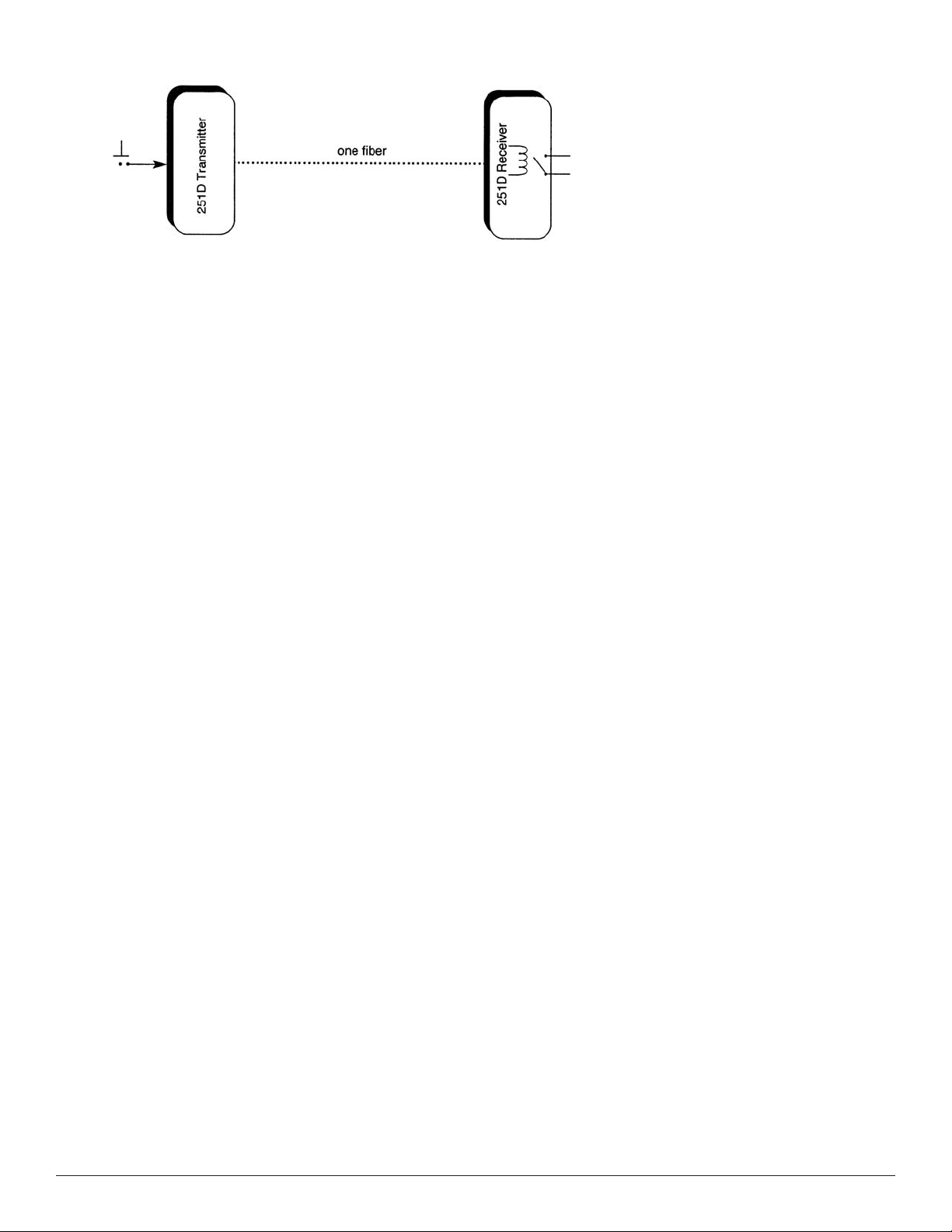
The 251D system transmits a single channel of switch/status information or control-function signals, one
way over a single fiber. Utilizing conventional multimode fiber, operating distances of up to two kilometers
and beyond can be obtained, depending on fiber conditions.
Modular units may be installed in a housing, above a ceiling panel, or in any location. Rack mount units
may be installed in a card cage for use in any standard 19-inch rack. Each unit occupies one rack slot.
Modular units may be powered by 13.5 VAC at 300 mA or 12 to 16 VAC at 6 W, or with the 610P AC Adapter
ed from the rack.
ailable fr
(av
om GE Security). Rack mount units are pow
er
OPTICAL INDICATOR
Receiv
If this LED is off, it indicates that optical power is not being received and would suggest that the fiber is
open or, less likely, the transmitter or receiver is inoperative.
IN CASE OF PROBLEMS
If problems should be encountered, first check to be sure power is properly connected to the modules.
Also verif
If any pr
following information available: exact model number, product code, and serial numbers of your fiber
optic links, and a listing of the diagnostic indicators and their respective color/condition.
ers include a STATUS indicator LED. When lit green, this LED would indicate the data path is complete.
y that the fiber is good. Then, check the transmitter status indicators. If lit, data is present.
oblems arise, please contact the GE Security customer service department and have the
Page 3

251D and 2251D
NOTE: To provide earth ground reference, Stand Alone (Enclosure) modules need
to be connected to a good earth ground. This can be accomplished by connecting
a copper-based conductor from the modules DC Common/Ground pin
to an approved earth ground.
Page 4

251D and 2251D
Customer Support
For assistance in installing, operating, maintaining, and troubleshooting this product,
refer to this document and any other documentation provided. If you still have questions,
please contact technical suppor
t during normal business hour
excluding holidays, between 6 a.m. and 5 p.m. Pacific Time).
GE Security
Call: 888 437-3287 (US, including Alaska and Hawaii; Puerto Rico; Canada)
Outside the toll-free area: 503 885-5700
Fax: 561 998-6224
gesecurity.com
.
www
U.S.
GESecurity.
.
www
As a company of innov
For the latest pr
11-0251-030212-A Released MAY-07
com
ation, GE Security r
oduct specifications visit GE Security online at www
T (561) 998-6100
T 888-GE-SECURIT
888 (437-3287)
F 561 998-6224
E gesecuritycustserv@ge.com
eserves the right to change product specifications without notice.
com or contact your GE Sales R
GESecurity.
.
Y
s (Monday thr
epresentative.
ough Friday,
Asia
T 852-2907-8108
F 852-2142-5063
Australia
T 613-9239-1200
F 613-9239-1299
Canada
T 519-376-2430
F 519-376-7258
Europe
T 44-113-238-1668
F 44-113-253-8121
Copyright © 2007 General Electric Company. All rights reserved.
Latin America
T 305-593-4301
F 305-593-4300
 Loading...