

Page 1
SuperBus 2000 2-Amp Power Supply 600-1019
Installation Instructions
Description
The power supply provides an additional 12 VDC, 2 amps
(current limited) for Concord 4 system devices and is
supervised via the SuperBus
® 2000 digital data bus. The
power supply uses a 24 VAC, 50 VA power transformer. In
case of an AC power failure, a 12 VDC, 4.5 or 7 Ah backup
battery (not included) provides power to connected devices.
The battery is tested by the power supply on power up, every
two minutes afterward, and whenever the panel tests its own
backup battery.
The power supply also includes a hardwire zone input that
accepts normally open (NO) or normally closed (NC) intrusion
detection devices. The power supply can be located inside the
Concord 4/Concord Express V4 cabinet or it can be mounted
in a separate Concord Residential Enclosure (444-1700 and
444-1711 ordered as a separate kit) or Concord Commercial
Expansion Enclosure (444-1391 ordered as 60-816).
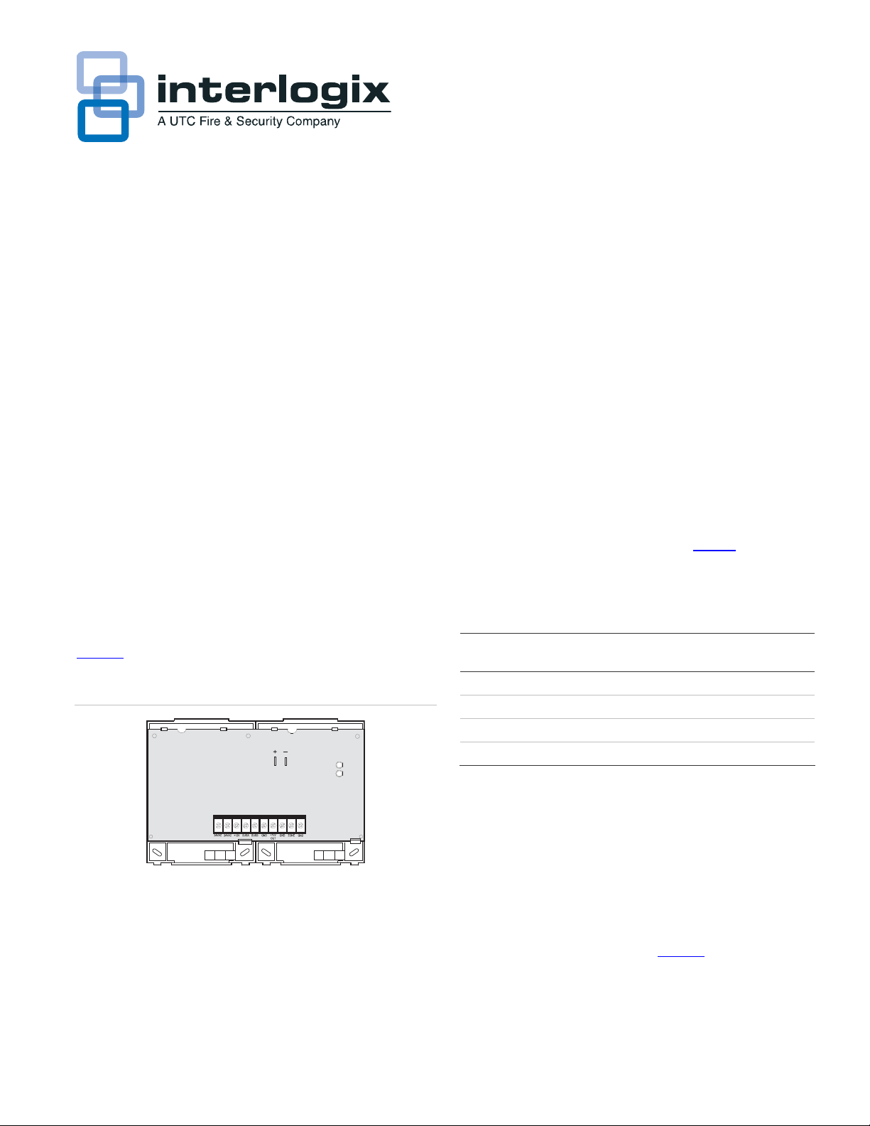
Figure 1
Figure 1. Power supply main components
describes the power supply main components.
Backup
Battery
Connections
Ter mi nal S tr ip
Red LED-bus
communication
status
Green LEDpower status
Installation
Use the following guidelines for installing the power supply.
Guidelines
• The power supply AC transformer must be plugged into an
AC outlet that is not a ground fault interrupt circuit (GFIC)
or controlled by a switch.
• When mounting the power supply inside the panel cabinet,
the backup battery can also be stored inside the panel
cabinet.
• When mounting the power supply in a separate enclosure,
the maximum wire length from the power supply bus and
power connections to the panel is 4,000 feet.
• When mounting the power supply in a separate enclosure,
the power supply mounting location should be determined
by the wire runs needed to provide power to devices with
minimal loss on the +12V OUT wire. Table
1 shows the
maximum wire runs between the power supply +12V OUT
terminal and the devices it will power.
Table 1. Maximum +12V OUT wire length
Gauge Maximum wire length from power supply +12V
OUT terminal
22 100 feet
18 200 feet
16 350 feet
14 550 feet
• For large installations with long wire runs, power supply
location is important. The total system wiring length (all
partitions) for all bus devices connected to a Concord 4/
Concord Express V4 panel must not exceed 4,000 feet.
This not only includes the power supply bus and power
connections to the panel, but also any bus devices you
may connect to the power supply. For example, touchpads
and other bus devices in a remote partition should be
connected to the power supply rather than running the
wires all the way to the panel (Figure 2
).
• Up to 16 SuperBus 2000 devices can be connected to
Concord 4/Concord Express V4 panels (touchpads,
receivers, transceivers, HIMs, HOMs, ESMs, etc.).
P/N 466-2185 • REV B • January 2011 1
Page 2
2. Bus device wiring example for remote partitions
Figure
Panel
Bus devices
connected to
panel
Power
supply
Bus devices
connected to
power supply
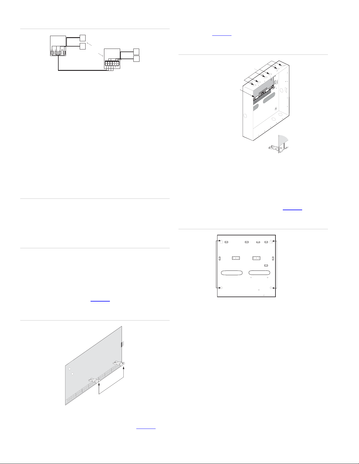
then snap the backplates on to the support standoffs
(Detail in Figure 4
Figure 4. Mounting power supply inside panel cabinet
).
Mounting
Clips
Tools and supplies
• 12 V backup battery (4.5 Ah part no. 60-681 or 7 Ah part
no. 60-680)
• Screwdrivers
• Separate enclosure—if not mounting power supply inside
panel cabinet
• Mounting screws
• Support Standoffs (included with panel)
• 4-conductor, 22- or 18-gauge stranded wire
• 2-conductor, 18-gauge wire (for AC transformer)
Mounting
Caution: To prevent damaging the panel or power supply,
remove the panel AC power transformer and disconnect the
backup battery before installation.
You must be free of static electricity before handling circuit
boards. Wear a grounding strap or touch a bare metal surface
to discharge static electricity.
Power Supply
on Backplates
Detail
Mounting inside Concord residential enclosure
1. Unplug the panel AC power transformer and disconnect
the backup battery.
2. Place the cabinet at the desired location and mark the
cabinet mounting holes and knockouts (Figure 5
Figure 5. Residential enclosure mounting holes and knockouts
).
Mounting inside panel cabinet
1. Unplug the panel AC power transformer and disconnect
the backup battery.
2. Install the support standoffs (included with panel) at the
panel locations shown in Figure 3
Figure 3. Installing panel support standoffs
.
4. Slide the top of the backplates onto the left and center
module mounting clips on the panel cabinet (Figure 4
),
Cabinet
Mounting
Knockout
Knockout
Holes (4)
3. Drill holes and insert the appropriate anchors where studs
are not present.
4. Run wires from all devices to be powered, to the power
supply.
5. Run a 4-conductor, 22-gauge or larger stranded wire from
the power supply to the panel.
6. Run a 2-conductor, 18-gauge stranded wire from the
power supply to the AC transformer location.
7. Feed all wires through the knockouts and secure the
cabinet to the wall with the included screws.
8. Remove the power supply circuit board from the plastic
mounting plates.
2 SuperBus 2000 2-Amp Power Supply 600-1019 Installation Instructions
Page 3

9. Position the plastic mounting plates in the cabinet on the
top-left or top-right side and secure them with the six selftapping screws included with the power supply (Figure 6
Figure 6. Power supply mounting positions in residential
enclosure (arrows indicate screw locations)
9. Secure the power supply to the cabinet using either the
right side or left side power supply mounting holes, with
).
the six self-tapping screws included with the power supply
(Figure 8
Figure 8. Power supply mounted in commercial enclosure
).
10. Re-install the power supply circuit board on the plastic
mounting plates.
Mounting inside Concord Commercial enclosure
1. Unplug the panel AC power transformer and disconnect
the backup battery.
2. Remove the necessary knockouts for wire access (Figure
7).
3. Place the cabinet at the desired location and mark the
Cabinet
Mounting
Holes (4)
).
cabinet mounting holes and knockouts (Figure 7
Figure 7. Commercial enclosure power supply mounting holes
and knockouts
Knockouts (4)
Power Supply
Mounting
Holes
Right Side Mounting
Left Side Mounting
Wiring
Connect the power supply to the panel terminals and devices
as shown in Figure 9
Figure 9. Power supply wiring connections to panel and devices
.
To bus
devices
To power
inputs on
devices
N/C circuit with 2k Ohm
Resistor (49-454)
N/O circuit with2k Ohm
Resistor (49-454)
Power Up
Use the following procedure for powering up the power supply
and panel to verify bus communication.
1. Verify that all wiring at the panel and devices are correct.
2. Connect the power supply backup battery to the battery
4. Drill holes and insert the appropriate anchors where studs
terminals on the power supply board (Figure 10
Figure 10. Power supply AC and DC power connections
).
are not present.
5. Run wires from all devices to be powered, to the power
supply.
6. Run a 4-conductor, 22-gauge or larger stranded wire from
the power supply to the panel.
7. Run a 2-conductor, 18-gauge stranded wire from the
RED BLACK
power supply to the AC transformer location.
8. Feed all wires through the knockouts and secure the
cabinet to the wall with the included screws.
SuperBus 2000 2-Amp Power Supply 600-1019 Installation Instructions 3
Page 4

3. Wire the power supply AC transformer to the power supply
board, then plug in the transformer (Figure 10
). The green
LED should turn on to indicate power is present. The red
LED should be off for the moment.
Note: If the green LED is not on, unplug the power supply
AC power transformer, disconnect the backup battery, and
proceed to Table
2 in “Troubleshooting”.
4. Connect the panel backup battery and plug in the panel
AC power transformer. The panel should automatically
scan for new bus devices and the red LED on the power
supply board should flicker to indicate bus communication
with the panel.
5. If using the optional zone input, learn the zone into panel
memory (see panel installation instructions).
Specifications
Panel compatibility Concord 4 series control panels
Power output required 24 VAC, 50 VA class II power transformer
Power output 12 VDC, 2.0 amps maximum, current limited
Battery type 12V, 4.5Ah or 7Ah lead acid
Standby load 95 mA (4.5Ah battery), 190 mA (7 Ah battery)
Operating temperature 32° to 120° F (0° to 49° C)
Storage temperature -30° to 140° F (-34° to 60° C)
Max. relative humidity 85%, non-condensing
Dimensions (LxWxD) 5.125 in. x 7.85 in. x 1.0 in. (13 cm x 20 cm x
2.5 cm)
Regulatory information
Troubleshooting
Table 2. Troubleshooting
Problem Action
Green LED is off 1. Check that power supply transformer is
plugged into outlet.
2. Check that transformer is not plugged into
an outlet controlled by a switch.
3. Check outlet circuit breaker/fuse. Reset/
replace as needed.
Red LED is off. Check/correct bus (A & B) wiring connections
at module and panel.
System touchpads
display AUX POWER
FAIL.
System touchpads
display AUX POWER
BATT trouble.
System touchpads
display AUX AC
POWER trouble.
1. Check for shorts on wire connected to
power supply +12V OUT terminal.
2. Verify that devices connected to power
supply +12V OUT terminal are not drawing
more than 2 amps.
1. Check that power supply battery is
connected.
2. Power supply battery needs charging.
Battery may need at least 4 hours to fully
charge.
1. Check that power supply transformer is
plugged into outlet.
2. Check that power supply transformer is not
plugged into an outlet controlled by a switch.
3. Check outlet circuit breaker/fuse. Reset/
replace as needed.
Manufacturer UTC Fire & Security Americas Corporation, Inc.
1275 Red Fox Rd., Arden Hills, MN 55112-6943,
USA
UL/cUL listings 985, 1023, and 1610
FCC compliance This device complies with FCC Rules Part 15.
Operation is subject to the following two
conditions. This device may not cause harmful
interference. This device must accept any
interference that may be received, including
interference that may cause undesired operation.
Changes or modifications not expressly approved
by Interlogix can void the user’s authority to
operate the equipment.
Contact information
For contact information, see www.utcfireandsecurity.com or
www.interlogix.com.
For technical support, toll-free: 888.437.3287 in the US
including Alaska, Hawaii, Puerto Rico, and Canada. Outside
the tool-free area, contact your dealer.
Copyright © 2011 Interlogix, a UTC Fire & Security Company.
All rights reserved.
4 SuperBus 2000 2-Amp Power Supply 600-1019 Installation Instructions
 Loading...