

Page 1

Zx10 6U Rack-Mount/Deskside
System Guide
May 2000
D1AA0042A
Page 2

Copyright
2000 Intergraph Computer Systems. All rights reserved. This document contains information protected by
copyright, trade secret, and trademark law. This document may not, in whole or in part, be reproduced in any form or
by any means, or be used to make any derivative work, without written consent from Intergraph Computer Systems.
Use, duplication, or disclosure by the United States Government is subject to restrictions as set forth in subdivision
(c)(1)(ii) of the rights in technical data and computer software clause at DFARS 252.227-7013. Unpublished rights are
reserved under the copyright laws of the United States.
Intergraph Computer Systems, Huntsville AL 35894-0001
Notice
Information in this document is subject to change without notice and should not be considered a commitment by
Intergraph Computer Systems. Intergraph Computer Systems shall not be liable for technical or editorial errors in, or
omissions from, this document. Intergraph Computer Systems shall not be liable for incidental or consequential
damages resulting from the furnishing or use of this document.
All warranties given by Intergraph Computer Systems about equipment or software are set forth in your purchase
contract. Nothing stated in, or implied by, this document or its contents shall be considered or deemed a modification
or amendment of such warranties.
Trademarks
Intergraph and the Intergraph logo are registered trademarks of Intergraph Corporation. Zx is a trademark of
Intergraph Computer Systems. Intel and Pentium are registered trademarks of Intel Corporation. ServerSet is a
trademark of ServerWorks Corporation. Microsoft, Windows, and Windows NT are registered trademarks of
Microsoft Corporation. Other brands and product names are trademarks of their respective owners.
FCC/DOC Compliance
This equipment has been tested and found to comply with the limits for a Class A digital device, pursuant to part 15 of
the FCC Rules. These limits are designed to provide reasonable protection against harmful interference when the
equipment is operated in a residential installation. This equipment generates, uses, and can radiate radio frequency
energy. If the equipment is not i nstalled and used in accordance with the inst ructions, it may cause harmful
interference to radio communications. Operation of this equipment in a residential area is likely to cause harmful
interference, in which case the user will be required to correct the interference at his own expense.
This Class A digital apparatus meets all requirements of the Canadian Interference-Causing Equipment Regulations.
Cet appareil numérique de la classe A respecte toutes les exigencies du Règlement sur le materiél brouilleur du Canada.
Page 3

Safety Notices
This is a user-serviceable system. However, there are no user-serviceable parts in the power supply. Please return the
power supply to the manufacturer for repair.
Service and upgrade tasks should be performed by users who can follow instructions in a manual to service equipment,
and can do so without harm to themselves or damage to the equipment.
The AC power cord for this unit is the service disconnect. Ensure the AC power outlet to which the system’s power
cord connects is close to the system and is easily accessible. For protection against electrical shock and energy
hazards, unplug the system’s power cord from its AC power outlet before opening or servicing the system.
If the AC voltage selection switch on the power supply is not set correctly, serious equipment damage may occur when
power to the system is turned on.
To reduce the risk of electrical sh ock and energy hazards, do not attempt to open the equipment unless instructed, and
do not use a tool for purposes other than instructed.
Internal components may be at high temperatures. Allow time for them to cool before handling them.
Internal components can be damaged by static electricity. Use an antistatic wrist strap connected to the bare metal of
the system’s chassis to protect against electrostatic discharge.
If a modem card used in the system receives ground from the system, ensure the system is connected to an earth-
grounded AC power outlet.
Notes
Changes or modifications made to the system that are not approved by the party responsible for compliance could void
the user's authority to operate the equipment.
Procedures in this document assume familiarity with the general terminology associated with personal computers, and
with the safety practices and regulatory compliance required for using and modifying electronic equipment.
Read all operating instructions before using this device. Keep these instructions for future reference. Follow all
warnings on the device or in the operating instructions.
To comply with the limits for an FCC Class B computin g device, always use shielded cables and the power cord
supplied with the system.
Page 4

Page 5

Contents
Preface............................................................................................................................................ix
About This Document......................................................................................................................ix
Document Conventions.................................................................................................................... ix
More Information ............................................................................................................................. x
Customer Support............................................................................................................................. x
1 Setting Up the Hardware............................................................................................................ 1
Deskside and Rack-Mount Systems.................................................................................................. 1
Unpacking the System...................................................................................................................... 2
Placing System Components............................................................................................................. 2
Before Mounting a Rack-Mount System.......................................................................................... 3
Understanding Rack-Mount Vertical Units ......................................................................................3
Mounting a Rack-Mount Base Unit.................................................................................................. 4
Connecting System Components...................................................................................................... 8
Locating Expansion Cards.............................................................................................................. 10
Installing Removable RAID Disk Drives........................................................................................11
Connecting External SCSI Devices ................................................................................................13
Connecting to AC Power ................................................................................................................14
Starting the System......................................................................................................................... 16
What’s Next?.................................................................................................................................. 16
v
2 Setting Up the Software ............................................................................................................17
Preparing for Setup......................................................................................................................... 17
Going Through Setup ..................................................................................................................... 19
Finishing Software Setup................................................................................................................ 20
Installing the Network Controller Driver..........................................................................20
Creating a SCSI Controller Driver Diskette..................................................................... 21
Creating an Emergency Repair Disk ................................................................................ 21
Installing Driver Software ................................................................................................21
Installing QFE Software ................................................................................................... 21
What’s Next?.................................................................................................................................. 22
3 Configuring the System............................................................................................................. 23
Configuring the Video Disp lay....................................................................................................... 23
Resetting the Video Display Resolution........................................................................... 23
Changing the Default Video Display Driver .................................................................... 24
Correcting Initial Video Display Problems...................................................................... 24
Configuring System Audio .............................................................................................................25
Configuring Networking................................................................................................................. 25
Configuring Peripheral Devices...................................................................................................... 25
Configuring RAID Disk Drives ...................................................................................................... 26
Changing Drive Letters................................................................................................................... 27
Changing Virtual Memory Settings ................................................................................................28
Configuring the SCSI Controller .................................................................................................... 28
Creating or Updating an Emergency Repair Disk........................................................................... 29
Page 6

vi
Configuring the BIOS..................................................................................................................... 29
What’s Next?.................................................................................................................................. 29
4 Operating the System......................................................................................................... ....... 31
Controlling System Power .............................................................................................................. 31
Reading System LEDs .................................................................................................................... 32
Using Automatic Shutdown............................................................................................................ 32
Starting and Stopping the System................................................................................................... 34
Observing Operating Precautions................................................................................................... 34
Using the Keyboard........................................................................................................................ 35
Using the Mouse............................................................................................................................. 36
Using the Floppy Disk Drive.......................................................................................................... 37
Using the CD-ROM Drive.............................................................................................................. 37
Reading Removable Disk Drive LEDs........................................................................................... 38
Responding to a Power Supply Alarm............................................................................................ 40
Using System Management Software............................................................................................. 41
Learning About the Operating System............................................................................................ 41
Using Hardware Security Features ................................................................................................. 41
Cleaning System Components........................................................................................................ 42
5 Troubleshooting Operational Problems.................................................................................. 43
Getting Started................................................................................................................................ 43
System Power ................................................................................................................... .............. 43
System Boot....................................................................................................................................44
Video.............................................................................................................................................. 46
Audio.............................................................................................................................................. 47
Network.......................................................................................................................................... 47
Peripheral Drive Errors................................................................................................................... 47
Miscellaneous Hardware.................................................................................................................48
6 Reinstalling the Operating System........................................................................................... 49
Before You Begin........................................................................................................................... 49
Finding Driver Software .................................................................................................................49
Installing the Operating System...................................................................................................... 50
Updating the Operating System...................................................................................................... 51
7 Gaining Access to System Components.................................................................................... 53
Before You Begin........................................................................................................................... 53
Avoiding Electrostatic Discharge................................................................................................... 53
Access Points.................................................................................................................. ................ 54
Removing and Replacing the Top Cover/Side Panel...................................................................... 55
Removing and Replacing the Front Panel....................................................................................... 56
Internal System Components.......................................................................................................... 57
8 Upgrading the System............................................................................................................... 59
Before You Begin........................................................................................................................... 59
Adding Expansion Cards ................................................................................................................59
Identifying Expansion Card Slots..................................................................................... 60
Page 7

vii
Installing an Expansion Card............................................................................................ 61
Assigning System Resources............................................................................................ 62
Disabling On-Board Controllers.......................................................................................62
Adding External SCSI Peripheral Devices ..................................................................................... 62
Choosing SCSI Cables..................................................................................................... 62
Choosing SCSI IDs .......................................................................................................... 63
Terminating SCSI Devices............................................................................................... 64
Connecting SCSI Devices................................................................................................ 64
Changing SCSI Controller or Device Settings..................................................................64
Adding Internal Peripheral Devices................................................................................................65
Adding Memory..............................................................................................................................66
Upgrading Processors..................................................................................................................... 66
9 Servicing the System.................................................................................................................. 67
Before You Begin........................................................................................................................... 67
Removable Disk Drive....................................................................................................................67
JBOD Disk Drive Cage Device.................................................................................................... .. 69
Peripheral Cage Device.................................................................................................................. 71
Expansion Card...............................................................................................................................74
Memory Module............................................................................................................................. 76
Processor Bus Terminator .............................................................................................................. 77
Processor Module............................................................................................................... ............ 78
RAID Disk Drive Cage................................................................................................................... 78
RAID SAF-TE Card....................................................................................................................... 80
Power Supply..................................................................................................................................81
Cooling Fans................................................................................................................................... 84
System Board..................................................................................................................................86
CMOS/Clock Lithium Battery........................................................................................................ 87
Intrusion Alert Switch..................................................................................................................... 87
Power Keyswitch and LEDs........................................................................................................... 88
10 System Hardware and Specifications..................................................................................... 91
Functional Diagram............................................................................................................. ........... 91
Internal Peripheral Cabling............................................................................................................. 92
EIDE Cabling................................................................................................................... 92
SCSI Cabling for RAID Systems...................................................................................... 93
SCSI Cabling for JBOD Systems .....................................................................................94
Floppy Disk Drive Cable.................................................................................................. 95
EIDE Peripheral Device Cage Cable................................................................................ 95
RAID SCSI External Port Cable...................................................................................... 95
RAID SCSI Peripheral Device Cage Cable...................................................................... 96
RAID SCSI Disk Drive Cage Cable................................................................................. 96
JBOD SCSI Peripheral Device Cage/External Port Cable............................................... 96
JBOD SCSI Disk Drive Cage Cable.................................................................................97
Power Supply and Cables............................................................................................................... 97
Cooling Fans................................................................................................................................... 98
Page 8

viii
Hardware Monitoring and Power Management.............................................................................. 99
System Configuration Summary..................................................................................................... 99
System Board................................................................................................................................100
System Specifications ................................................................................................................... 101
Returned Goods Authorization (RGA) Form
Warranty Procedure and Repair Address Labels
Page 9

Preface
The System Guide describes how to set up and configur e your Intergraph Co mputer Systems Zx10
6U deskside or rack-mount system. The System Guide also provides information on operating,
servicing, and upgrading your Zx
About This Document
The System Guide is organized as follows:
♦ Chapter 1, “Setting Up the Hardware,” describes how to set up the system’s hardware.
♦ Chapter 2, “Setting Up the Software,” describes how to set up the operating system and
associated system software.
♦ Chapter 3, “Configur ing the System,” describes how to configure the system for use.
♦ Chapter 4, “Operating the System,” describes how to use essential features and provides other
basic information on operating the system.
♦ Chapter 5, “Troubleshooting Operational Problems,” describes how to resolve basic problems
you may encounter when using the system.
ix
10 6U system.
♦ Chapter 6, “Reinstalling the Operating System,” describes how to reinstall the operating
system and associated system software, if required.
♦ Chapter 7, “Gaining Access to System Components,” describes how to open the system and
gain access to major internal components.
♦ Chapter 8, “Upgrading the System,” provides information on adding and upgrading maj or
system components.
♦ Chapter 9, “Servicing the System,” describes how to remove and replace major components.
♦ Chapter 10, “System Hardware and Specifications,” provides technical reference information
and system specifications.
Document Conventions
Bold
Italic Variable values that you supply, or cross-references.
Monospace
SMALL CAPS Key names on the keyboard (such as D, ALT, or F3) and names of files and
Commands, words, or characters that you key in literally.
Output displayed on the screen.
directories. You can type filenames and directory names in the dialog boxes or
the command line in lowercase unless directed otherwise.
Page 10

x
CTRL+D Press a key while simultaneously pressing another key; for example, press CTRL
and D simultaneously.
More Information
See the Late-Breaking News (if provided) for important hardware, software, and documentation
details not covered in this document.
For more detailed information on the operating system, see the printed and online Microsoft
documentation delivered with the system.
For detailed information on the system board, system board components, and basic input/output
system (BIOS), see the System Board Manual delivered with the system.
Read the Ergonomics Guide delivered with your system for valuable information on ways to
minimize repetitive stress injuries when working with a comp uter.
Customer Support
Intergraph Computer Systems hardware has a factory warranty ranging from 30 days to three years.
A detailed warranty description is available on the World Wide Web. You can also take advantage
of other available hardware support services.
Intergraph Computer Systems provides complimentary software support for 30 or 90 days
following shipment of a hardware or software product. At the end of the complimentary support
period, you can take advantage of other levels of software support.
To get more information on support services:
♦ Visit the Support pages on the World Wide Web at http://www.intergraph.com/ics.
♦ In the United States, call 1-800-414-8991.
♦ Outside the United States, contact your local Intergraph Computer Systems subsidiary or
distributor.
To visit Intergraph Computer Systems on the World Wide Web:
Use your World Wide Web browser to go to http://www.intergraph.com/ics.
Page 11

To get customer support by telephone:
♦ In the United States, call 1-800-633-7248 between the hours of 7:00 a.m. and 7:00 p.m.
Central Time, Monday through Friday (e xcept holidays).
♦ Outside the United States, contact your local Intergraph Computer Systems subsidiary or
distributor.
♦ Have the following information available when you call:
− Your service number, which identifies your site to I ntergrap h Computer Systems. You
use your service number for warranty or maintenance calls.
− Your Customer Personal Identification Number (CPIN). You get a CPIN the first time
you call the Customer Response Center; it is associated with your service number for
future call logging.
− The product’s name or model number.
− The product’s serial number. Software product serial numbers are included in the product
packaging. Hardware product serial numbers are on a sticker affixed to the hardware
product.
− Your name and telephone number.
− A brief description of the question or problem.
xi
Page 12

xii
Page 13
1 Setting Up the Hardware
This chapter describes how to set up the hardware for your system.
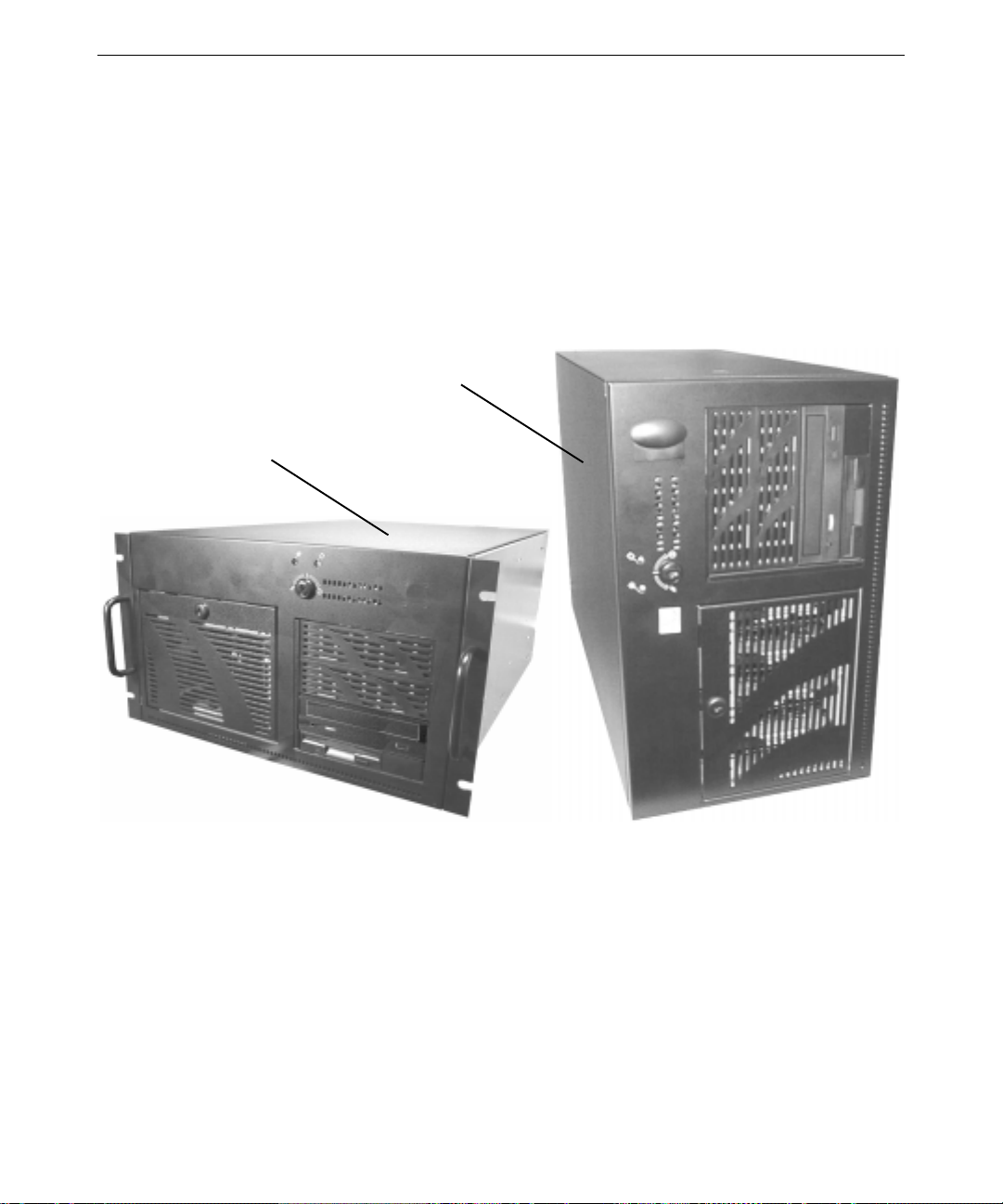
Deskside and Rack-Mount Systems
Your system was delivered with a deskside base unit or a rack-mount base unit, as shown in the
following figure.
Deskside
Rack-Mount
1
The deskside base unit is designed for office environments. The base unit can sit beside a desk or
on another sturdy surface close to the user. Access to the inside of the base unit is through the left
side panel (as seen from the front of the system).
The rack-mount base unit is designed for back-office environments such as server farms or
equipment rooms. The base unit mounts in a standard 19-inch equipment rack in use at your site.
Access to the inside of the base unit is thro ugh t he top cover.
Page 14

2
Unpacking the System
WARNING The base unit is heavy! To avoid personal injury or damage to equipment, use
two persons to move the base unit.
CAUTION Remove and move items carefully. Do not drop items on a hard surface, or damage
to internal components may result. You may need help to move heavy items.
Remove everything from the shipping cartons and verify you have (at a minimum) these items:
♦ System documentation, includ i ng System Guide, System Board Manual, and Late-Breaking
News (if provided)
♦ Operating system software CD, diskettes, and documentation
♦ Driver software CD
♦ Keyboard and mouse
♦ System base unit and two power cords
♦ Rack-mounting hardware ( rack-mount system only)
♦ Monitor, power cord, and video cable (if purchased)
If any of these items were not delivered, call Intergraph Computer Systems at 1-800-633-7248.
Save the packaging materials. If yo u need to r eturn equipment for repair, it must be in its original
packaging for you to get warranty service.
Placing System Components
When placing system components, keep these guidelines in mind:
♦ A deskside system should be placed on the floor or on a surface capable of supporting the full
weight of the system.
♦ A rack-mount system should be mounted in a 19-inch equipment rack in use at your site.
♦ Place the system in an area where air can circulate freely around it.
♦ Do not expose the system to high levels of dust, smo ke, or moisture.
♦ Maintain a temperature range of 50 °F to 90 °F (10 °C to 32 °C); the optimum operating
temperature is 70 °F (21 °C).
♦ Maintain a humidity range of 20 percent to 80 percent non-condensing; the optimum humidity
is 50 perc ent non-condensing.
Page 15

Before Mounting a Rack-Mount System
Before mounting a system in an equipment rack in use at your site, prevent the rack from moving
by engaging its stabilizers. If the rack is not equipped with stabilizers, refer to the rack
documentation for stabilizing instructions.
Observe the following safety precautions when mounting the system’s base unit in a rack in use at
your site or when using the rack-mounted system:
♦ Extend only one slide rail set at a time. Push an extended slide rail set back into the rack
before extending another .
WARNING Extending more than one slide rail set could cause the rack to fall forward,
causing damage to equipment and injury to anyone in front of the rack.
♦ Do not push on or lean against the rack. Always engage the stabilizers. The adjustable feet
should be lowered securely against the floor.
♦ If the rack contains an AC distribution box or an uninterruptible power supply (UPS), do not
connect its the power cord to the wall outlet until instructed to do.
♦ Set up the system completely before you start it.
WARNING Do not move the rack with equipment mounted or powered on, or damage to
internal components may occur. Shut down the system, unplug the system
power cords from their AC power outlets, remove all equipment, and then move
the rack.
3
Understanding Rack-Mount Vertical Units
A vertical unit (U) is an industry-standard measurement for rack-mounted equipment. Small
markers on the rack mounting rails usually indicate each vertical unit. For more information, see
the documentation for the racks in use at your site.
You should determine the vertical mounting space within a rack enclosure taken up by each device
you want to install. For example, an AC distribution box may require 1U or 2U of mounting
space, while the system’s base unit requires 6U of mounting space.
Note the following about vertical units:
♦ A vertical unit (U) equals 1.75 in (4.45 cm) and consists of three mounting holes.
♦ The mounting hole d iameter is 7.1 mm (industry standard).
♦ Mounting holes are counted upward after locating the first mounting hole within the range of
vertical units required to install the equipment.
Page 16
4
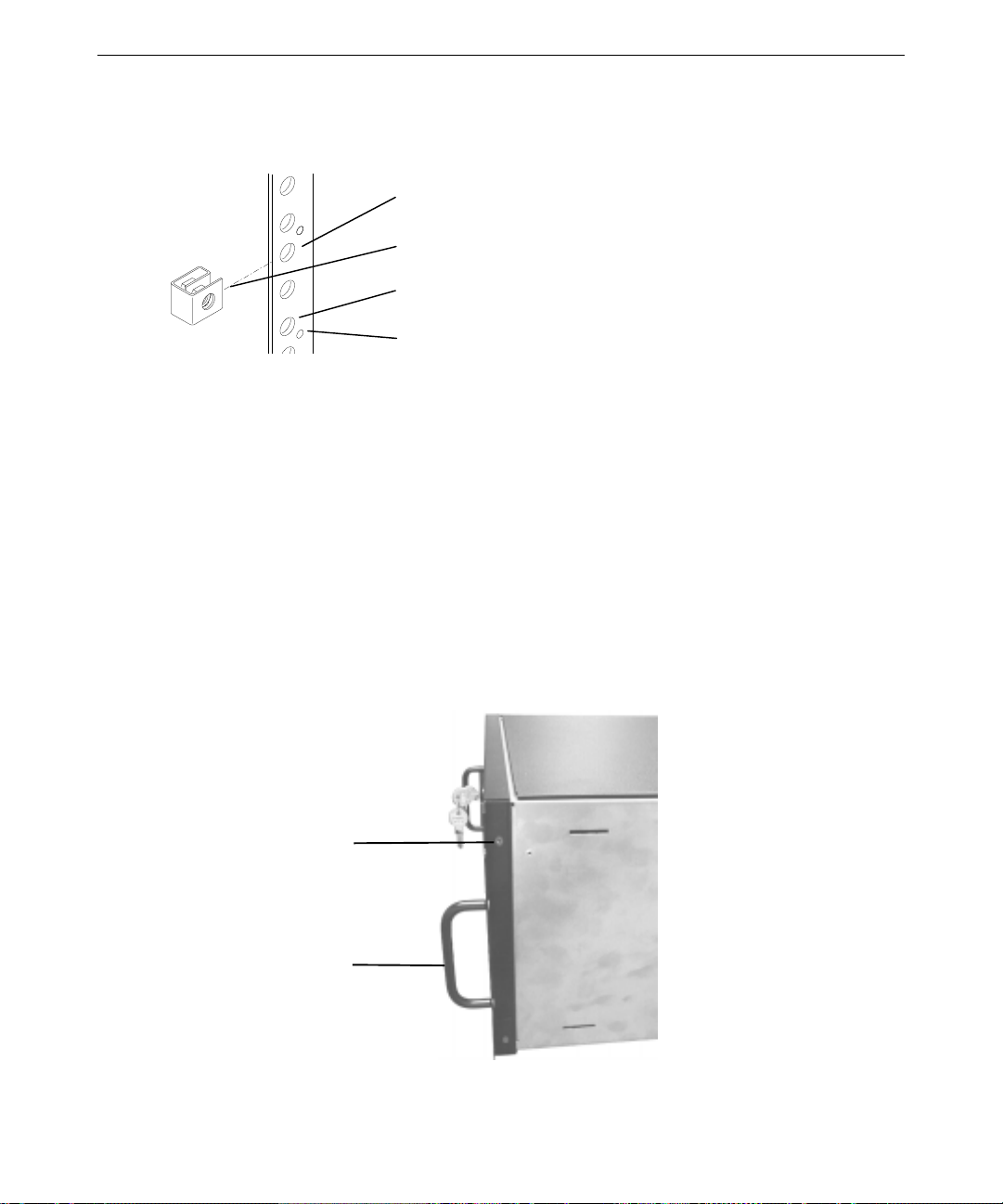
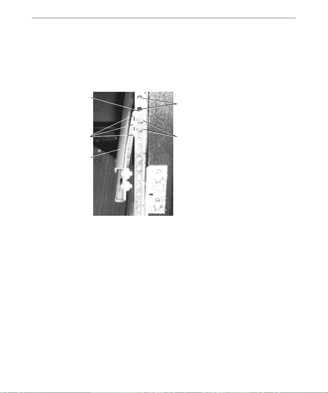
The following figure shows the typical installation of a tinnerman nut to mounting hole 3 of a
vertical unit.
Mounting Hole 3
Tinnerman Nut
Mounting Hole 1
Vertical Unit Marker
Mounting a Rack-Mount Base Unit
The following procedure describes ho w to mount a rack-mount system’s base unit in a typical
19-inch equipment rack. For detailed information on mounting equipment in a rack, see the
documentation for the equipment racks in use at your site.
WARNING The base unit is heavy! To avoid personal injury or damage to equipment, use
two persons to mount the base unit in an equipment rack.
To mount the base unit in an equipment rack:
1. Remove the screws securing each side of the front panel to the base unit. Holding each handle
bracket in place, replace the screws through each bracket and the front panel into the base
unit.
Handle Bracket -
Front Panel Screw
(Two each side)
Handle Bracket
(One each side)
Page 17
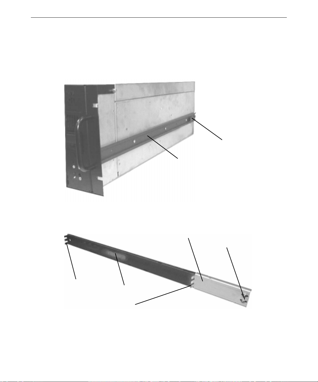
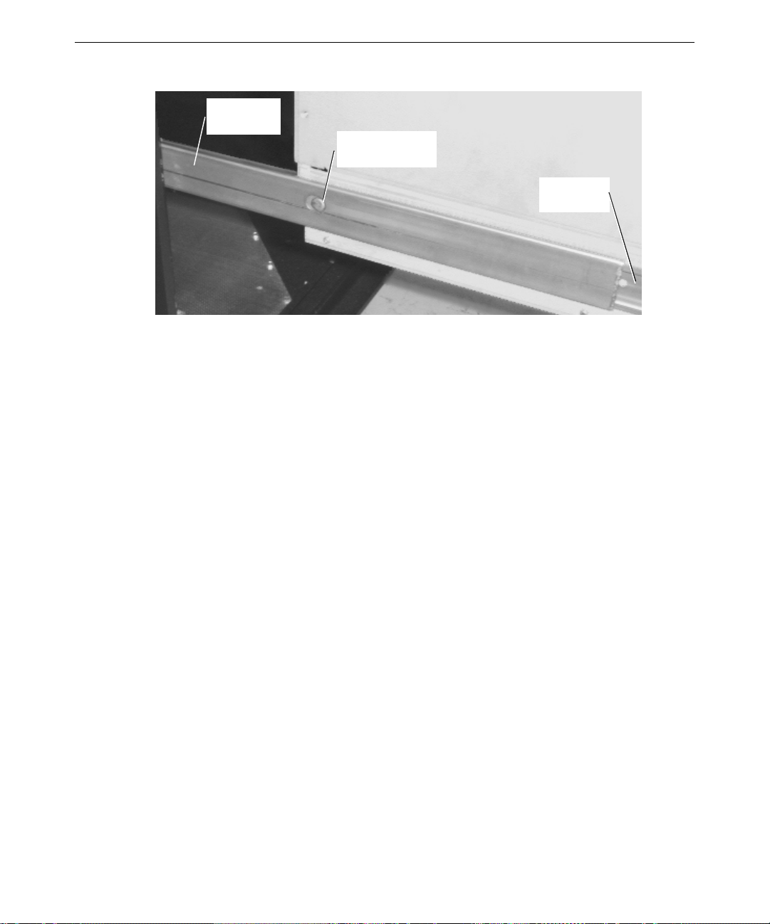
2. Remove the guide from each of the two rails. The guide is the innermost-sliding piece of the
rails, and has a flexible tab at one end.
3. Attach a guide to each side of the base unit using the flat-head screws provided, making sure
the flexible tab on the guide is toward the back of the base unit. Align each guide with the
lower set of three screw holes in each side of the base unit.
Flexible Tab
Guide (One each side)
5
4. Use the button-head screws and bolts provided to loosely secure a bracket to each rail. The
bracket has the teeth needed to secure the rail to the equipment rack. Install the button-head
screws and bolts loosely so you can adjust the back teeth positions later.
Bracket
Bolts
Front Teeth
Side Tab
Back Teeth
5. The rack-mount base unit requires 6U (10.5 in or 26.7 cm) of mounting space. Choose the
five vertical units you need and, on the equipment rack mounting rails, mark the fifth and sixth
mounting holes from the bottom of this 6U space.
Page 18
6
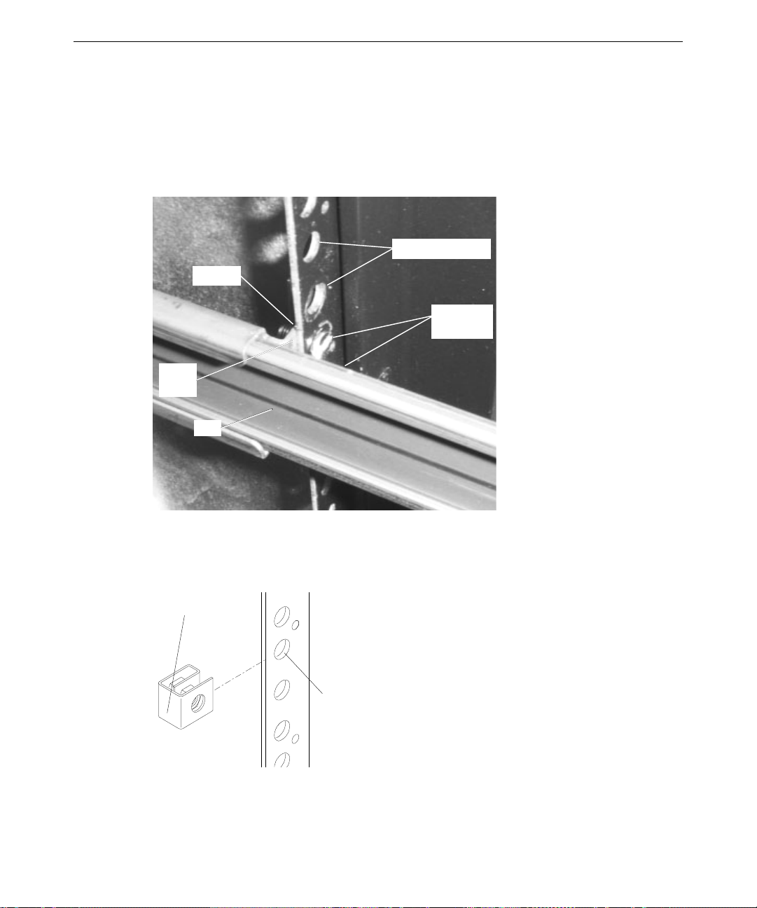
6. Use the flat-head screws and bar nuts to secure the front teeth on both rails to the front
mounting rails of the equipment rack.
With the flat side of each bar nut facing the screws, loosely install two flat-head screws to
each bar nut, through the fifth and sixth mounting holes from the bottom of the 6U space.
Slide the front teeth over the screws and tighten. Ensure the front teeth are between the bar
nuts and the mounting holes.
Mounting Holes
Bar Nut
Flat-Head
Screws
Front
Teeth
Rail
7. On the front mounting rails on the equipment rack, slide tinnerman nuts over the third and
thirteenth mounting holes from the bottom of the 6U space. The tinnerman nuts will be used
when you secure the handle brackets on the front of the base unit to the front mounting rails of
the equipment rack.
Tinnerman
Nut
Mounting
Hole
Page 19
8. Use the button-head screws and bar nuts provided to secure the back rail teeth to the back
mounting rails of the equipment rack.
With the flat side of each bar nut facing the screws, loosely install two button-head screws to
the bar nut, through the fifth and sixth mounting holes from the bottom of the 6U sp ace. Slide
the back teeth over the screws and tighten. Ensure the back teeth are between the bar nuts and
the mounting holes.
7
Bar Nut
Teeth
Rail
Mounting
Holes
Button-Head
Screws
9. At the back of the equipment rack, tighten the screws and bolts on the brackets of each rail.
10. Extend the rails from the equipment rack until they lock.
11. With a person on each side, lift the base unit and align the rails with the guides attached to the
sides of the base unit. Slide the base unit into the rails until you hear a click.
12. Press the locked rail tabs and slide the base unit completely back into the equipment rack.
After the base unit slides back a few inches, the base unit and rails slide together as a unit into
the equipment rack. See the following figure.
Page 20
8
Rail
(Each side)
Locked Rail Tab
(Each side)
13. Install the black screws through the handle brackets and the t innerman nuts you installed
previously to secure the base unit to the front mounting r a ils of the equipment rack.
Connecting System Components
CAUTION If you do not use the cables delivered with the system, use shielded cables to
prevent excessive electromagnetic interference (EMI). The cables delivered with the
system reduce the amount of EMI produced by the system.
Guide
(Each side)
NOTE You should disconnect the cables from the base unit before extending it from the
rack, but if needed, you can extend the base unit without disconnecting the cables.
Be sure there is enough cable to allow the base unit to fully extend from the rack.
Use caution not to pinch the cables while extending or retracting the base unit.
After placing the system components, connect them together using the included cables. The base
unit and other system components ha ve keyed and labeled por ts, to make it easier to connect them
together with the right cables. If you cannot connect a cable easily, ensure that you are aligning the
cable connector correctly with the port.
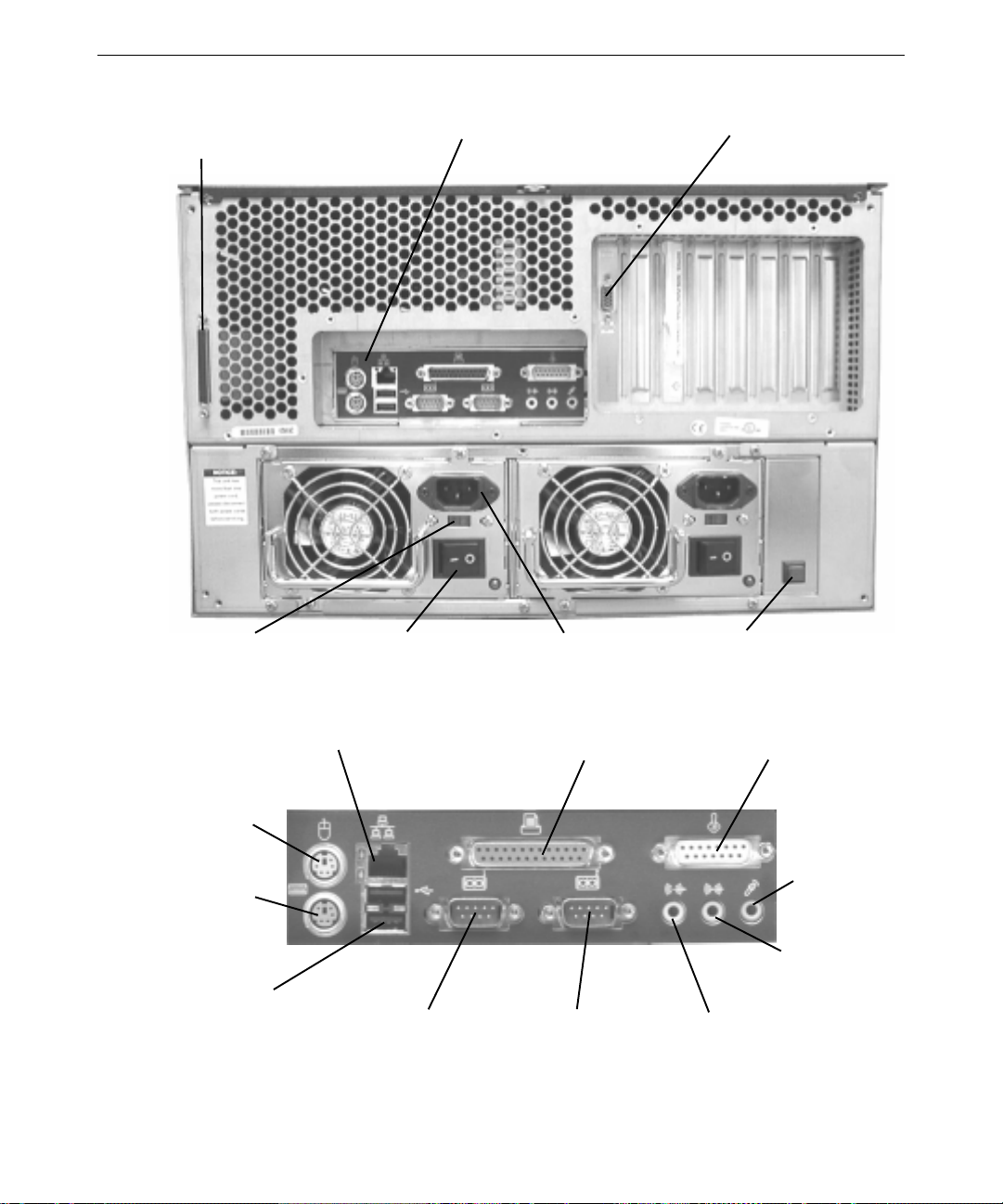
The following figures illustrate the back of the base unit. Most ports on the back of the base unit
are colored and labeled with icons for easy reference. Locations of expansion cards and their ports
may differ from those shown.
NOTE On a deskside system, the SCSI port is at the top and the expansion ports are at the
bottom (as seen when facing the back of the base unit).
Page 21
9
(
)
SCSI Port
AC Voltage
Selection Switch
Power Supply
Power Switch
Input/Output (I/O)
Panel (See below)
AC Power
Receptacle
Video Out
(Typical) (Blue)
Power Supply
Alarm Cutoff
Ethernet Network
Mouse
(Green)
Keyboard
(Purple)
Universal Serial
Bus (USB)
Serial (COM 1)
(Teal)
Serial (COM 2)
(Teal)
Parallel (LPT)
(Burgundy)
MIDI/Game
(Gold)
Microphone
Pink
Audio Line In
(Light Blue)
Audio Line Out
(Lime)
Page 22
10
To connect the system components:
1. Connect a video cable from the monitor to the video out port on the graphics controller card.
See the graphics controller documentation for more information.
2. Connect cables from the keyboard and the mouse to their ports.
3. Connect cables from sp eakers and a microphone (if available) to their ports. You may need to
connect the speakers to AC power; see the speaker documentation for more information.
4. Connect a cable from your site’s Ethernet network to the Ethernet port.
5. Connect a cable from a parallel peripheral device to the parallel port.
6. Connect cables from any serial peripheral devices to the serial ports.
7. Connect cables from any USB peripheral devices to the USB ports.
8. Connect the cable from any external SCSI peripheral devices, or a SCSI terminator module, to
the SCSI port. See “Connecting External SCSI Devices” in this chapter.
CAUTION If you do not connect an external SCSI peripheral device to the SCSI port on a JBOD
system, connect a terminator module to the port.
9. Connect cables to ports on any other installed expansion cards as required. See the expansion
card documentation for more information.
10. Install removable disk drives in the disk drive cage. See “Installing Removable Disk Drives”
in this chapter.
CAUTION Do not connect the system power cords to the base unit or to AC power outlets at
this time. See “Connecting to AC Power” later in this chapter for more information.
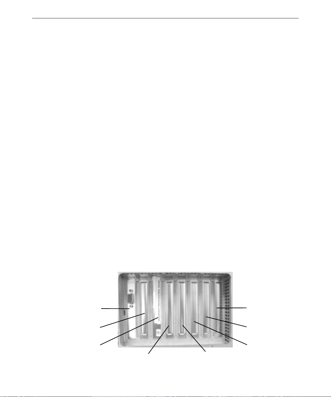
Locating Expansion Cards
Expansion cards are installed as needed in the Accelerated Graphics Port (AGP), Peripheral
Component Interconnect (PCI), and Industry Standard Architecture (ISA) expansion slots.
Slot 1—AGP
Slot 2—PCI
Slot 3—PCI
Slot 4—PCI
Slot 7—ISA
Slot 7—PCI
Slot 6—PCI
Slot 5—PCI
Page 23
The following table describes the expansion slots and any typically installed expansion cards.
Note that Slot 7 is a shared PCI/ISA slot; you can install a PCI expansion card or an ISA
expansion card in this slot, but not both.
11
Slot
1 (Left or top) AGP Graphics controller
2 PCI (64-bit/33 MHz) Varies by system
3 PCI (64-bit/33 MHz) RAID controller
4 PCI (64-bit/33 MHz) Varies by system
5 PCI (64-bit/66 MHz) Varies by system
6 PCI (64-bit/66 MHz) Varies by system
7 PCI (64-bit/33 MHz) Varies by system
7 (Right or bottom) ISA Varies by system
CAUTION If a modem card used in the system receives ground from the system, ensure the
system is connected to an earth-grounded AC power outlet.
For information on installing or connecting to expansion cards, see Chapter 8, “Upgrading the
System,” and the expansion card documentation delivered with the system.
Type Typical Expansion Cards Installed
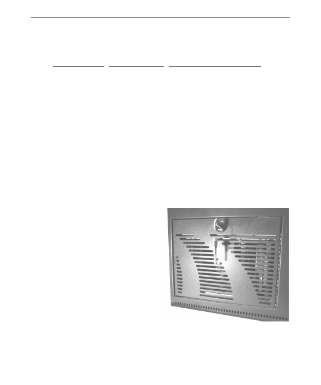
Installing Removable RAID Disk Drives
In a RAID system, the base unit’s disk
drive cage may contain up to four
removable low-voltage differential (LVD)
SCSI disk drives. An installed RAID
controller card manages these disk drives
and provides RAID capabilities to the
system.
These SCSI disk drives can be accessed
through a door on the front panel. On a
rack-mount system, the door is to the right
(as seen when facing the front of the
system). On a deskside system, the disk
drive cage door is at the bottom (as seen
when facing the front of the system). A key
(delivered with the system) locks and
unlocks the disk drive door.
Page 24
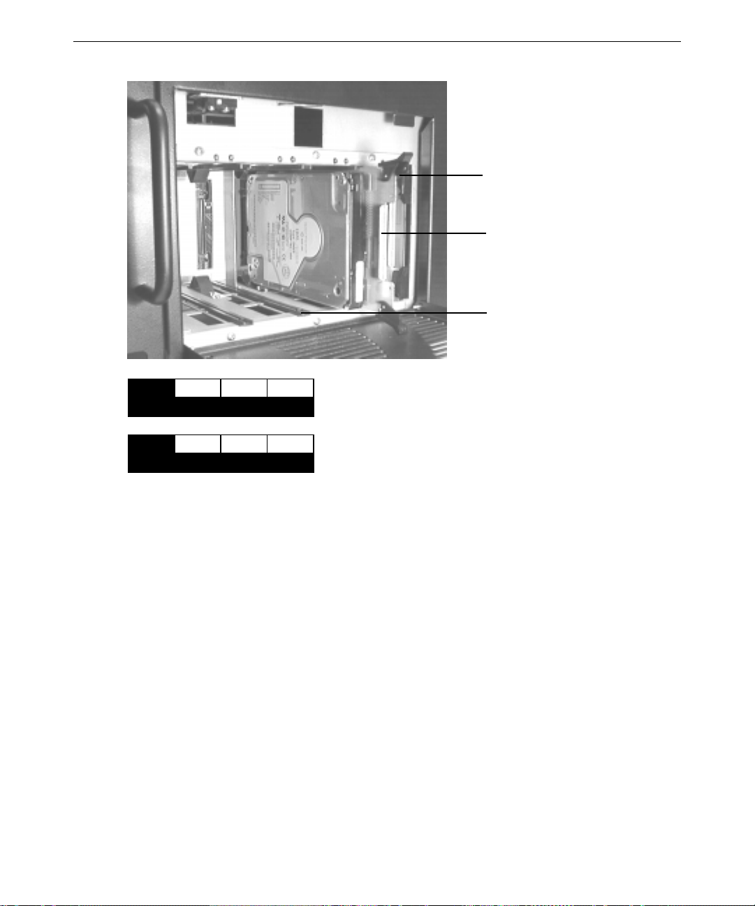
12
Latch Clip (Top and bottom)
Disk Drive Mounting Plate
Disk Drive Rail (Typical)
x GB
ADP
100
CH ID
Each SCSI disk drive installed in the disk drive cage has a
label affixed to the front. The left side of the disk drive label
identifies the disk drive size (in GB). The label has blank
spaces for the numbers to indicate the adapter (ADP), the
x GB
ADP
CH ID
channel (CH), and the identification number (ID). Standard
disk drives include values for the adapter, channel, and
identification number filled in. Additional disk drives have a
blank label (supplied) that you must complete after
installation.
To install removable drives:
1. Open the disk drive cage door on the front of the base unit.
2. Carefully remo ve the disk drives from their carton and place them on an antistatic surface.
Open the antistatic bags and remove the disk drives. Note the ID number on the disk drives.
3. Extend the latch clips on Drive 0 and align the upper and lower edges of the disk drive’s
mounting plate with the disk drive rails at the right end or top end of the disk drive cage. For
a rack-mount system, the mounting plate faces to the right; fo r a deskside system, the
mounting plate faces up.
4. Push the disk drive at the center between the latch clips until it slides all the way onto the rails
and firmly engages its connector. The latch clips rotate closed as you push the disk drive onto
the rails.
5. Repeat steps 3 and 4 to install each remaining disk drive, moving to the left or down as you
install each new disk drive. Do not leave empty rails between disk drives.
Page 25
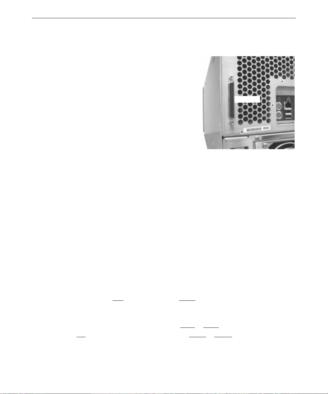
Connecting External SCSI Devices
The system has a dual-cha nnel low-voltage differential
(LVD) SCSI controller integrated on the system board.
Depending on your system configuration, you can
connect external Ultra, Ultra2, or Ultra3 SCSI devices to
this controller through the SCSI por t on the back of the
base unit.
CAUTION On a RAID system, do not connect
external SCSI peripheral devices to the
non-functional SCSI port on the RAID
controller card.
CAUTION On a JBOD system, if you do not connect
an external SCSI peripheral device to the
SCSI port, connect a terminator module to
the port.
NOTE On a deskside system, the SCSI port is at the top when facing the back of the base
unit.
To ensure data integrity and promote optimum performance:
13
SCSI Port
♦ Use the shortest cables possible to connect SCSI peripheral devices.
♦ Use high-quality SCSI cables to ensure adequate shielding (impedance of 110 to 135 ohms).
To connect external SCSI devices:
1. If the system is connected to AC power and operating, shut down the system and unplug the
system power cord from its AC power outlet.
2. If a terminator module is connected to the SCSI port on the system, remove it.
3. Connect one end of a SCSI cable to the SCSI port on the system.
4. Connect the other end of the SCSI cable to a SCSI peripheral device.
5. Connect a SCSI cable between SCSI ports on any additional SCSI peripheral devices.
6. Set the SCSI ID of each peripheral device to a unique
SCSI ID number. Do not use any SCSI
ID numbers already used by the system.
7. For each SCSI peripheral device connected to the port, if the device is:
− The last or only device on the SCSI chain, install or enable
SCSI termination
− Not the last or only device on the SCSI chain, disable or remove SCSI termination
Page 26

14
8. Ensure that the power switch on each peripheral device is in the off position; then connect the
power cord from each peripheral device to an AC power outlet.
9. Turn on power to all connected SCSI peripheral devices, and then start the system.
10. If necessary, install software drivers and configure the peripheral devices according to the
vendor’s instructions.
See Chapter 8, “Upgrading the System,” for additional details on installing external SCSI
peripheral devices.
Connecting to AC Power
CAUTION The Power switches on the unit’s two power supplies are the service disconnect. To
remove AC power from the system, you must turn the Power switch on both power
supplies to the OFF ( O ) position.
CAUTION Ensure the AC power outlets to which the system’s power cords connect are close to
the system and are easily accessible
The system has two power supplies. Both must be connected to AC power for the system to
operate correctly. However, if one power supply fails, you can replace it without shutting down
the other power supply. This hot-swap capability lets you ha ndle a p ower supply failure without
shutting down and powering down the entire system.
When you connect the system’s base unit to AC power and turn the Power switches on both power
supplies to the ON ( | ) position, auxiliary power is applied to the system. Auxiliary power ensures
that system components power up quickly when needed. See Chapter 4, “Operating the System,”
for more information on controlling system power.
Page 27
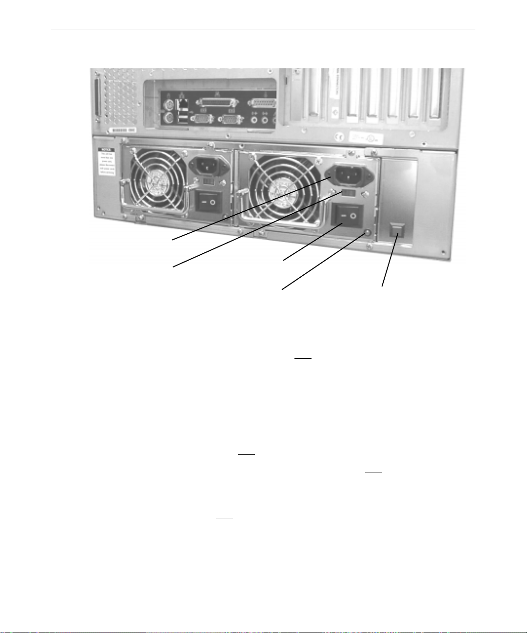
AC Power
Receptacle
AC Voltage
Selection Switch
Power Supply
Power Switch
Power Supply
LED
15
Power Supply
Alarm Cutoff
Switch
To connect the system to AC power:
1. Make sure the AC voltage selection switches on both power supplies (on the back of the base
unit) are set to the proper line voltage for your location.
− If your location uses 90 to 135 volts, the number 115 must be visible.
− If your location uses 180 to 264 volts, the number 230 must be visible.
WARNING If you do not set the AC voltage selection switches on the power supplies
correctly, equipment damage may occur when you connect the system to AC
power.
2. Make sure the Power switches on both power supplies are set to the OFF ( O ) position.
3. Connect the system’s power cords to the AC power receptacles on both power supplies.
4. Connect the power cords from the monitor, base unit, and any external peripheral devices to
properly grounded three-prong AC power outlets.
5. Turn the Power switches on both power supplies to the
ON ( | ) position. This applies auxiliary
power to the system. The power supply light-emitting diodes (LEDs) light when the power
supplies are operating.
Page 28
16
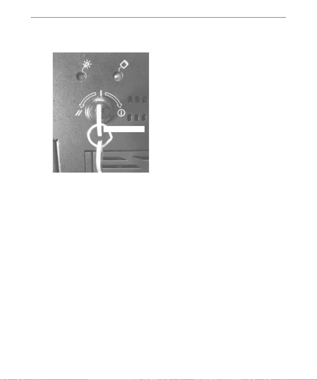
Starting the System
Power Keyswitch
CAUTION If you start the system, and then turn it
off before completing the instructions in
Chapter 2, “Setting Up the Software,”
you will have to reinstall the operating
system and associated system software.
See “What’s Next” for more information.
CAUTION Before starting the system for the first
time, you may want to learn more about
system power, startup, and shutdown.
See Chapter 4, “Operating the System,”
for more information.
To start (apply full power to) the system, turn the
Power keyswitch shown in the following figure to the
right (clockwise), and then release it.
What’s Next?
You can do the following to prepare your system for use:
♦ If you want to get going with the default setup, go to Chapter 2, “Setting Up the Software,” to
start the system and go through o perating system Setup. If you start the system and then
turn it off before completing operating system Setup, you will have to reinst all the
operating system and associated system softw are.
♦ The opera t i ng system is already installed through the first phase of the Setup process. If you
want to reload the operating system and associated system software instead of comp leting
Setup, see Chapter 6, “Reinstalling the Operating System.”
♦ On a RAID system, the default RAID setup is disk drives striped to RAID level 5, with a
write-through write po licy. The defaul t setup is descr i bed in more detail in Chapter 3,
“Configuring the System.”
Page 29

2 Setting Up the Software
This chapter describes how to set up the operating system and associated system software for your
system.
Preparing for Setup
Your system’s primary hard disk drive was formatted and partitioned before shipment. In Explorer
or My Computer, you can right-click a disk drive and click Properties to display the drive’s
partition size and file system format. If yo u purchased other disk drives, you may have to format
and partition them for use. See the operating system documentation and Help for more
information on formatting, partitioning, and administering disk drives.
The operating system and associated system software is installed on the system’s primary hard disk
drive. Installed system software includes:
♦ Driver software for the SCSI controller, graphics controller, audio controller, and mouse
♦ Driver software for peripheral devices and expansion cards installed at the factory (including
the RAID controller in a RAID system)
17
♦ Core networking software
♦ The latest certified operating system Service Pack software, if needed
♦ Quick-Fix Engineering (QFE) software, if needed
♦ System management software
The operating system is installed through the fi rst phase of the Setup process. You must follow the
Setup process to prepare the operating system for use.
Before you go through operat ing system Setup, have the following documents availab l e:
♦ Microsoft’s operating system documentation
♦ Documentation for the system’s graphics controller and any installed peripheral devices and
expansion cards
♦ Late-Breaking News (if provided)
Page 30

18
Get and record the following information:
Your name, and the name of your company or
organization:
The Product Identification Number from
Microsoft’s documentation, Certificate of
Authenticity, or registration card:
A user name fo r a user account:
If the system is connected to a network, get and record the following information for your system
from your network administr ator:
Computer name:
Workgroup name (if the system will be part of
a workgroup):
Domain name (if the system will be part of a
domain):
If the system will be a server, get and record the following information for your system from your
network administrator:
Security role for your server in the domain:
primary domain controller, backup domain
controller, or stand-alone server:
If your server will be acting as a backup
domain controller or a stand-alone server, user
name and password of an authorized domain
administrator account:
NOTE Determine the security role for your server before beginning system configuration.
You cannot change a stand-alone server to a domain controller without reinstalling
the operating system. A domain controller maintains security policy and performs
user authentication for a domain. Stand-alone servers may be part of a domain, but
they do not have to participate in the domain. See the operating system
documentation for more information.
Page 31

If the system is connected to a network that uses the Transmission Control Protocol/Internet
Protocol (TCP/IP), get and record the appropriate TCP/IP information for your system from your
network administrator:
Internet Protocol (IP) address:
IP subnet mask:
IP domain name fo r your network:
IP addr ess for your network’s de fault gateway:
IP addresses for Domain Name System (DNS)
servers, if any:
IP addresses for Windows Internet Name
Service (WINS) servers, if any:
The operating system delivery media contain software and drivers for both Reduced Instruction Set
Computing (RISC)- and Intel-based systems. When installing operating system software, make
sure you install it from the \
I386 directory on the delivery media.
Going Through Setup
19
Power Keyswitch
CAUTION If you start the system and then turn it
off before completing operating system
Setup, you will have to reinstall the
operating system and associated system
software.
CAUTION Before starting the system for the first
time, you may want to learn more about
system power, startup, and shutdown.
See Chapter 4, “Operating Notes,” for
this information.
To start (apply full power to) the system, turn the
Power keyswitch on the fr ont of the base unit to the
right (clockwise) and then release it.
Page 32

20
The first time you start the system, it boots to a Microsoft End User License Agreement (EULA).
After reading and accepting the terms of the agreement, follow the instructions to continue
operating system Setup. Take the default settings provided by Setup, except as noted in the
following text. You can set up a user account and join a workgroup or domain after you configure
the system for use.
To start the computer and go through Setup:
1. Turn on power to the monitor.
2. Turn on power to the base unit. The system starts and the EULA displays.
3. Read the terms of the EULA and then follow the instructions displayed to complete the Setup
process. When prompted, enter the Product Identification Number.
NOTE You must enter the Product Identification Number before you can continue Setup.
You cannot complete Setup if you do not enter this number.
When going through Setup:
♦ Do not let Setup auto-detect the system’s networ k controller. After completing Setup, install
the network controller driver software from diskette. See “Finishing Software Setup” for
instructions.
♦ If prompted to create an Emergency Repair Disk, do so.
♦ If prompted to enter a password for the Administrator account, do so.
♦ If you do not create a user account during Setup, press
to log on to the operating system.
♦ You can use the C:\
Setup files. If you delete the
I386 directory when prompted for the location of the operating system’s
I386 directory from the system’s hard disk, you must have access
to an operating system CD-ROM to use the operating system’s Setup files.
After you complete Setup and restart the system, you can set up a user account and join a
workgroup or domain if needed. See the operating system documentation and operating system
Help for more information on Setup, creating a user account, and joining a workgroup or domain.
Finishing Software Setup
After completing operating system Setup, you must take some additional steps to finish setting up
the system software.
Installing the Network Controller Driver
Setup completed without auto-detecting the system’s network controller. To enable networking,
you must manua lly install the network controller driver software from diskette.
ENTER or select OK at the logon dialog
Page 33

The network controller driver software is in a folder on the system’s driver CD. First see the
README.TXT file for information on creating a driver diskette using the MAKEMS.BAT program.
Then see the
operating system Control Panel. Keep the driver diskette for use if you have to reinstall the
operating system.
MS.TXT file for information on installing the driver software using Network in the
Creating a SCSI Controller Driver Diskette
If you reinstall the operating system, you must install the SCSI controller driver software from
diskette. You cannot install it from the system’s driver CD.
The SCSI controller driver software is in a folder on the system’s driver CD. Copy the contents of
the version number folder (including any folders beneath it) to diskette. If you have to reinstall the
operating system, use this diskette when asked for the SCSI controller driver software.
Creating an Emergency Repair Disk
If you did not create an Emergency Repair Disk during Setup, you should do so after completing
Setup and configuring the system. See the operating system documentation and Help for
information on creating an Emergency Repair Disk.
21
You can use the files on the Emergency Repair Disk to restore the contents of the operating system
registry and the standard operating system driver software. You should update the Emergency
Repair Disk frequently, especially after adding or changing system hardware or software.
Installing Driver Software
Driver software (or drivers) for system components and peripheral devices was installed before
shipment. You received a CD with your system that contains these drivers. Keep the driver CD in
case you have to reinstall drivers or the operating system later.
Because of production timing, drivers for your system may have been revised after your system
shipped from the factory. You should check Intergraph Computer Systems’ online services for the
latest versions of your system’s drivers. If a later version of a driver is available, you can
download it and install it on your system; keep it on diskette in case you need to reinstall it later.
See the Preface of this document for information on the online services, and see the
delivered with a driver for installation instructions.
Installing QFE Software
Quick-Fix Engineering (QFE) software cont ains fixes for ope rating system problems or limitations;
these fixes are required for proper operation of your system. QFE software, when required, is
delivered on the system’s driver CD, and additional QFE software ma y be delivered o n diskette. If
README file
Page 34

22
you received QFE software with your system, it was installed before shipment. Keep the QFE
software in case you have to reinstall it or the operating system later.
Because of production timing, the QFE software for your system may have been revised after your
system shipped from the factory. You should check Intergraph Computer Systems’ online services
for the latest version of the QFE software for your system. If a later version is available, you can
download it and install it on your system; keep it on diskette in case you need to reinstall it later.
See the Preface of this document for information on the online services, and see the
delivered with the QFE software for installation instructions.
What’s Next?
See Chapter 3, “Configuring the System,” to configure the system for use.
See Chapter 4, “Operating the System,” for information on operating the system.
See Chapter 6, “Reinstalling the Operating System,” if you need to reinstall the operating system
and associated system software.
README file
Page 35

3 Configuring the System
This chapter describes how to configure basic components of your system for use.
Configuring the Video Display
The first time you start the system, your monitor displays a resolution of 1024 x 768. For the
system to use the installed graphics controller at other display resolutions, you must configure the
video display driver as described in this section.
Go to Display in the operating system’s Control Panel to configure the video display driver, or
right-click an open space on the operating system desktop and click Properties in the pop-up menu.
You can change the settings for color depth, desktop size, font size, refresh rate, and display type
of the system’s video display. You can also determine which type of graphics controller is
installed on your system.
23
See the graphics controller documentation delivered with the system, and any
delivered with the video display driver, for detailed configuration instructions. For more
information on configuring the video display, see the operating system documentation and Help.
Resetting the Video Display Resolution
If the monitor connected to your system does not support a resolution of 1024 x 768, you can reset
the video display to another resolution.
To reset the video display resolution:
1. Restart the system.
2. At the boot screen, select the VGA mode option, and then log on to the operating system.
3. Go to Display in the operating system’s Control Panel.
4. Select a resolution appropriate for your system's monitor.
5. Click Test to test the new video mode.
6. If prompted to restart the system, do so.
README files
Page 36

24
Changing the Default Video Display Driver
After configuring the video display and restarting the system, you may need to configure the
system to use the installed video display driver by default.
To change the default video display driver:
1. Go to System in the operating system’s Control Panel.
2. Under Startup/Shutdown, select the appropriate non-VGA option from the Startup list.
Correcting Initial Video Display Problems
If the system’s video display is black, not synchronized, or distorted after you restart the system,
you may have a video configuration problem. Do not press
to correct the problem by using the Last Known Good option to return the system to the last known
good configuration recorded by the operating system.
To use the Last Known Good option:
1. Power down and restart the system.
2. Press the space bar when prompted to display the Last Known Good menu.
CTRL+ALT+DEL to log on. Instead, try
If using the Last Known Good option fails to correct the video display problems, you can obtain a
functional video resolution by restarting the system in VGA mode.
To restart the system in VGA mo de:
1. Power down and restart the system.
2. At the boot screen, select the VGA mode option.
After logging on in VGA mo de, check for the following common pro blems and solutions:
♦ A multi-sync monitor is selected, but a graphics display device with different video timings is
connected to the system. Select a different monitor type.
♦ The monitor selection is incorrect. Select a different monitor type.
♦ There is not enough video display memory to support the selected resolution and color depth.
Install and reconfigure the video display to use a lower resolution and color depth.
Restart the system and, when the boot screen displays, select the appropriate non-VGA version of
the operating system to use the reconfigured video display driver. If problems persist, contact the
Customer Response Center for help.
Page 37

Configuring System Audio
The system has a PCI audio controller integrated on the system board. The required driver
software was installed before shipment.
If you connect a microphone and speakers to their ports on the I/O panel, you can use the audio
mixer software to control the speaker volume, the microphone input level, and other system audio
features. The audio mixer is available from the operating system’s taskbar tray. You can also
configure audio levels by using the operating system’s Volume Control and audio control
programs. The Volume Control is available from the operating system’s taskbar tray.
For more information on using the audio control programs, see the operating system
documentation and Help. For more information on the audio controller, see the System Board
Manual.
Configuring Networking
The system has a 10 Mbit/100 Mbit Ethernet network controller integrated on the system board.
The network controller features remote management and Wake-On-LAN capabilities. The
required driver software was installed before shipment.
25
Before you configure networking, ensure that the system is connected to the network. Then go to
Network in the operating system’s Control Panel to configure networ king. Follow the instructions
provided to set up the system to connect to and communicate over a network. Be sure to set up the
appropriate network protocols, such as TCP/IP, for the network to which you are connecting the
system.
After installing network protocols, you may need to reinstall the appropriate operating system
Service Pack software as recommended by Microsoft. See the Service Pack documentation
delivered with the system for more information.
See the operating system documentation and Help for more information on setting up the operating
system to use a network. For more information on the network controller, see the System Board
Manual.
Configuring Peripheral Devices
If you install additional peripheral devices in the system, you will have to install and configure the
associated driver software. You may also have to install or configure any associated application
software to use the devices.
Page 38

26
You can use the default backup tools provided with the operating system to run a tape drive. Go to
Backup on the Administrative Tools program menu. See the operating system documentation and
Help for more information.
See the documentation delivered with the peripheral devices for information on installing and
configuring driver software and associated application software. See the operating system
documentation and Help for information on using peripheral devices with the operating system.
Configuring RAID Disk Drives
In a RAID system, up to four removable low-voltage differential (LVD) SCSI disk drives are
installed in the system’s disk drive cage. An installed RAID controller card manages these disk
drives. The RAID controller provides the system with RAID capabilities such as disk striping,
mirroring, and redundancy for the removable disk drives.
The disk drive locations in the disk drive cage are numbered from 0 to 3, starting with the rightmost or top-most location. Each location also has a corresponding SCSI ID number, which is
determined by the hardware configuration of the disk drive cage and the RAID controller to which
it is connected.
Each installed removable disk drive has a label to identify it.
The spaces above ADP, CH, and ID are filled in before
shipment to identify the drives.
04 GB
ADP
0
CH
1
ID
♦ ADP identifies the RAID controller connected to the disk drive cage.
♦ CH identifies the RAID controller’s SCSI bus channel.
♦ ID identifies the disk drive’s SCSI ID.
Up to four removable disk drives may be installed and configured with the RAID controller
software at the factory. These disk drives are configured to appear as one logical disk drive in
Window NT Disk Administrator. The logical disk drive has a 2 GB NTFS system disk partition.
The rest of the logical disk drive is formatted as one NTFS partition, for a total of two partitions.
The default configuration for factory-installed RAID disk drives is as follows:
♦ RAID level 5
♦ Write-through write policy
♦ Two disk drives spin up every twelve seconds
You can use the RAID controller software to manage the RAID disk drives.
Page 39

The following table shows the correlation between the disk drive locations in the disk drive cage,
the disk drive SCSI IDs, and disk drive IDs in the RAID controller BIOS and the RAID controller
software.
27
Disk Drive
Location
0 (right or top) 0 ADP 0, CH 0, ID 0 1
1 1 ADP 0, CH 0, ID 1 2
2 2 ADP 0, CH 0, ID 2 4
3 (left or bottom) 4 ADP 0, CH 0, ID 4 5
NOTE SCSI ID 3 and RAID controller target ID 3 are reserved for the SAF-TE card on the
disk drive cage.
For more information on configuring and managing the RAID disk dr i ves and using the RAID
controller software, see the RAID controller documentation delivered with the system.
Disk Drive
SCSI ID
Changing Drive Letters
If you have more than one hard disk drive or CD-ROM drive, you may need to reassign system
drive letters. See the operating system Help for more information.
To change drive letters:
1. Exit all applic ations currently running on your system.
2. Go to Disk Administrator in the Administrative Tools program menu.
3. Select a hard disk drive or the CD-ROM drive.
Disk Drive Label
RAID Controller
Target ID
4. From the Tools menu, click Assign Drive Letter.
NOTE If you select the current drive or an otherwise locked drive, you must restart the
system to complete the drive letter reassignment.
5. Select a new drive letter to assign to the drive from the list. Click OK, and then click Yes to
continue.
6. If necessary, click OK, and then click Yes.
7. Repeat steps 2 through 6 for each drive letter assignment that you want to change.
8. Click Partition, then click Exit. If necessary, restart the system to complete the drive letter
reassignments.
Page 40

28
Changing Virtual Memory Settings
If you have more than one hard disk drive, you may need to change size and location of your
virtual memory page file. See operating system Help for more information.
Consider the following before changing page file sett ings:
♦ The size of the page file. If yo ur system is equipped with a large amount of RAM, Setup
might create a page file that is unnecessarily large.
♦ Drive letter reassignments. If you reassigned yo ur d r ive letters, you may find it necessary to
adjust your page file settings.
To change the size and location of the virtual memory page file:
1. Go to System in the operating system’s Control Panel.
2. Under Performance, click Change .
3. Click a drive letter in the list, and then type new values in the Initial Size and Maximum Size
text boxes.
4. Click Set.
5. Repeat steps 3 and 4 for any additional drives in the list.
6. Click Close, and then click OK.
7. When prompted, click Yes to restart the system with the new settings, or click No to continue
with other tasks and use the new settings the next time you restart the system.
Configuring the SCSI Controller
The system has a dual-channel SCSI controller integrated on the system board. Depending on your
system’s hardware configuration, this low-voltage differential (LVD) SCSI controller manages
internal and external Ultra, Ultra2, and Ultra3 SCSI peripheral devices. You may need to use the
SCSI Configuration Utility to configure the operation of SCSI peripherals connected to the
controller.
You may need to change SCSI controller parameters fo r a single SCSI peripheral device:
♦ If you are advised to do so by technical support or by the vendor documentation.
♦ If the SCSI device does not negotiate properly with the controller.
♦ If you exceed the maximum cable length for connecting SCSI devices to the system. See
Chapter 8, “Upgrading the System,” for more information.
♦ If you connect non-Ultra SCSI external devices to the system.
Page 41

To run the SCSI Configuration Utility:
Press
CTRL+C when prompted during system boot.
To get online help in the SCSI Configuration Ut ilit y:
Press
F1 to see information on the item currently highlighted on screen.
Creating or Updating an Emergency Repair Disk
If you did not create an Emergency Repair Disk during Setup, you should do so after completing
Setup and configuring the system. See the operating system documentation and Help for
information on creating an Emergency Repair Disk.
You can use the files on the Emergency Repair Disk to restore the contents of the operating system
registry and the standard operating system driver software. You should update the Emergency
Repair Disk frequently, especially after adding or changing system hardware or software.
Configuring the BIOS
The system’s basic input/output system (BIOS) reco rds basic system operating parameters, suc h a s
the amount of memory, the boot sequence, and the type of video display. The BIOS is stored in
flash-programmable memory, and reads the system parameters in the system’s complementary
metal-oxide semiconductor (CMOS) memo ry. When you power off the system, a battery provides
power to CMOS memory to retain the system parameters. Each time you power on the system, the
BIOS uses these stored parameters to configure the system for operation.
29
The BIOS Setup program, which is also stored in flash-programmable memory, allows you to
manually change the system operating parameters. You can run the BIOS Setup program as the
system boots, during the system’s power-on self-test (POST). For more information on the BIOS
Setup program and how to use it to configure the BIOS, see the System Board Manual.
What’s Next?
See Chapter 4, “Operating the System,” for basic information on operating the system.
See Chapter 6, “Reinstalling the Operating System,” if you need to reinstall the operating system
and associated system software.
Page 42

30
Page 43

4 Operating the System
This chapter contains important, basic information on operating your system.
Controlling System Power
CAUTION The Power switches on the unit’s two power supplies are the service disconnect. To
remove AC power from the system, you must turn the Power switch on both power
supplies to the OFF ( O ) position.
When you connect the system’s base unit to AC power and turn the Power switches on both power
supplies to the ON ( | ) position, auxiliary power is applied to the system. Auxiliary power ensures
that system components power up quickly when needed.
The Power keyswitch is a momentary contact switch, changing system states when the switch is
turned. Depending on the system’s current power state, you can use the Power keyswitch to start,
shut down, and power down the system.
31
Power LED
CAUTION Shut down the operating system before powering down the system. Simply turning
the Power keyswitch can cause data corruption or loss. Use Automatic Shutdown or
the operating system’s shutdown options first. See this and following sections for
more information.
Disk LED
Power Keyswitch
Page 44

32
Turn Power keyswitch right… To…
Momentarily (less than 1 second) Bring the system to full power from a powered-down state
Momentarily (less than 1 second) Start Automatic Shutdown to shut down the ope r a ting system
And hold it for at least 4 seconds Power down the system without using Automatic Shutdown
See “Using Automatic Shutdown” for more information on control l ing system power.
Reading System LEDs
The LEDs on the faceplate describe the current operational state of the system.
and start the operating system
and power down the system
or after using the operating system’s shutdown function
If the Power LED is…
Unlit Auxiliary power is off (fans are not running) or there is a system
Amber Auxiliary power is on; power consumption is reduced
Blinking green Auxiliary power is on; the system is in an ACPI-compliant power
Steady green Full power is on; power conservation is per device
If the Disk LED is…
Unlit The system’s disk drives are not active.
Lit and blinking The system’s disk drives are active.
Lit and unblinking There may be a problem with one or more disk drives.
Then…
failure (fans ar e running)
conservation state managed by the operating system; power
consumption is reduced
Then…
Using Automatic Shutdown
The Automatic Shutdown Utility contains more options for shutting down the system than the
operating system’s shutdown function. You can use this utility to shut down the oper a ting system
and power down the system in a number of ways.
To run Automatic Shutdown:
♦ Double-click the Automatic Shutdown icon in the operating system’s taskbar tray, or
♦ From the operating system Start menu, go to Automatic Shutdown Utility on the Automatic
Shutdown Utility menu.
♦ While the system is running, turn t he Power keyswitch right momentarily (less t han 1 second).
Page 45

By default, Automatic Shutdown is set for a 10-second delay. You can use the slider under Time
Remaining to set a delay of up to 30 seconds. Always set a delay greater than 5 seconds to ensure
that you have time to stop system shutdown if needed.
When you run Automatic Shutdown, the Auto matic System Shutdown dialog displays. To
configure Automatic Shutdown, choose an option in the dialog and click Apply. When you are
finished configuring the utility, click Start Shutdown. After you start the system again, the utility
will use the settings you selected.
The Automatic System Shutdown dialog contains the following options:
33
Options
Description
Shutdown the Computer Performs an orderly shutdown of the operating system. When
complete, turn the Power keyswitch right for 4 seconds to power
down the system, or restart the operating system.
Power Down the Computer Performs an orderly shutdown of the operating system, then
powers down the system.
Shutdown System and Restart
the Computer
Close All Programs and Log
On as Different User
CAUTION Use Power Down the Computer to power down the system. If you use Shutdown the
Computer, you must turn the Power keyswitch right and hold it for 4 seconds to
power down the system. You may “suspend” the system if you hold the Power
keyswitch for less than 4 seconds. If the operating system does not support a
Suspend mode, you must then power down the computer before you can restart the
system.
Performs an orderly shutdown of the operating system, then
powers down and restarts the system.
Closes your logon to the operating system and returns to the
operating system logon prompt.
The Automatic System Shutdown dialog also provides these functions:
Option
Description
Force All Processes to Terminate T er minates all programs if checked. If this option is not
checked the system displays an End Task dialog for each
process that may still be running.
Time Remaining Sets the time to delay before starting shutdown. When
Automatic Shutdown runs, this ti mer begins counting do wn.
Press
ENTER or click Stop Shutdown to stop the timer.
Stop Shutdown/Start Shutdown Stops or starts the shutdown timer. This button toggles
between Stop and Start.
See Automatic Shutdown Help for more information on this utility.
Page 46

34
Starting and Stopping the System
To start the system:
1. With the system connected to AC power and both power supplies turned on, turn the Power
keyswitch to the right (clockwise) to bring the system to full power.
2. At the boot menu, select the appropriate operating system option, and then press
To log on to the operating system:
1. If the logon dialog does not display, press
2. If user accounts have been set up, type a user name and a password into the appropriate fields.
3. If appropriate, type a domain name into the appropriate field.
4. Select OK or press
To log off, restart, shut down, or power down the system:
1. From the operating system Start menu, go t o Shut Down.
2. Click the appropriate option to log on as another user, restart, or shut down.
3. When prompted that it is safe to shut down the system, turn the Power keyswitch to the left
(counter-clockwise) to bring the system down to auxiliary power.
CAUTION The Power switches on the unit’s two power supplies are the service disconnect. To
remove AC power from the system, you must turn the Power switch on both power
supplies to the OFF ( O ) position.
For more information on starting and stopping the operating system, see the operating system
documentation and Help.
ENTER.
CTRL+ALT+DELETE to display it.
ENTER.
Observing Operating Precautions
Observe the following precautions when operating the system:
♦ When restarting the system, use the operating system controls instead of turning the Power
keyswitch off and on. Use the Power keyswitch only when instructed, or as the last alternative
for restarting the system.
♦ Never turn off power to the base unit when the disk access LED is lit.
♦ After turning off power to the base unit, wait at least 30 seconds before turning the power on
again. This allows the power supply to stabilize and the disk drives to stop spinning.
Page 47

Using the Keyboard
y
The system’s PS/2-compatible keyboard includes the following features:
35
♦ 104 standard keys, including special application function keys (
F1 through F12), arrow keys
for moving the cursor, and numeric keys in a keypad.
♦ Special keys for use with Wi ndows operating systems. Pr essing the left or right Windows key
(on either side of the space bar) displays the operating system Start menu and Taskbar.
Pressing the Application key (to the right of the space bar) displays an application-specific
pop-up menu.
Function
Keys
Windows Key
Windows Ke
Numeric
Keypad
Application
Key
Arrow
Keys
Some keyboard keys have sp ecial functions:
Key
ESC Usually assigned to an application-specific function; often used to exit.
PRINT SCRN Depending on the application in use, prints the displayed screen to a printer.
SCROLL LOC K Prevents the screen from scrolling.
PAUSE Temporarily suspends screen scrolling or some opera tions.
CAPS LOCK Types all letters as capitals.
NUM LOCK Activates the numeric keypad.
CTRL Used with another key for application-specific functions.
ALT Used with another key for application-specific functions.
DELETE Deletes characters.
Function
Page 48

36
You can use the Windows keys with other keys to perfo rm certain oper ating system functions:
Key Combination
Windows + F1 Display a pop-up menu for the selected object
Windows +
Windows +
Windows +
Windows +
Windows +
TAB Activate the next button on the taskbar
E Run Explorer
F Run Find Document
CTRL + F Run Find Computer
M Minimize all windows
SHIFT + Windows +
Windows +
R Display the Run dialog
Using the Mouse
The system’s PS/2-compatible mouse is a tracking device that controls the movement and
positioning of the pointer (or cursor) displayed on the screen in a graphical display environment.
Action
M Restore all windows
Wheel
To use the mouse, ensure it is connected to the system. Place the mouse on a clean, flat surface,
such as a desktop or a mouse pad. Rest your hand on the mouse, with a finger on each button and
the thumb to the side. Move the mouse across the flat surface to move the pointer on screen.
You can use the mouse to perform several actions:
Action
Description
Point Move the mouse to point to your selection on the screen.
Click Press and release the left mouse button once.
Double-click Press and release the left mouse button twice.
Drag Press and hold the left mouse button, then move the mouse. Release the button
when you finish dragging your selection to a new loca tion.
Right-click Press and release the right mouse button once.
Scroll On a wheel mouse, move the wheel back and forth to scroll in an application.
Page 49

You can find more information on using the wheel mouse by right-clicking the mouse icon in the
taskbar tray, or by going to Mouse in the operating system’s Control Panel.
Using the Floppy Disk Drive
The system’s floppy disk drive occupies a 3.5-inch external peripheral device bay, and is
accessible through a 3.5-inch slot on the front of the base unit. The drive accepts standard 3.5-inch
720 KB and 1.44 MB diskettes.
Drive LED
37
Eject Button
Follow these guidelines to use the floppy disk drive:
♦ To insert a diskette, slide the diskette with the arrow facing up into the slot. Push the diskette
in until it clicks into place and the eject button pops out.
♦ Before removing a diskette, ensure the drive LED is not lit.
♦ To remove a diskette, push the eject button and pull the diskette out of the slot.
♦ To protect the data on a diskette from being overwritten or erased, slide the write-protect tab
on the diskette toward the diskette edge until it snaps into place.
Using the CD-ROM Drive
The system’s CD-ROM drive occupies a 5.25-inch external peripheral device bay, and is
accessible through a tray or a slot at the front of the base unit. The drive supports software
ejection of discs and has an external amplified headphone jack.
Page 50

38
Headphone
Jack
Volume
Control
Drive LED
Eject Button
To use the CD-ROM drive:
♦ To insert a CD, press the eject button to extend the tray. Place the disc, printed side up, in the
tray and press the eject button again to retract the tray. If the CD-ROM drive is in a vertical
orientation, extend at least three of the tabs or clips in the drive tray to hold the disc in place.
♦ To remove a CD, press the eject button, and remo ve the disc after the tray extends. Then
press the eject button again to retract the tray.
♦ The media player programs included with the operating system allow you to listen to audio
compact discs. Insert an audio CD, printed side up, into the drive and start the media player
application. Adjust the volume using the operating system’s sound control programs.
♦ Adjust the volume control on the drive for headphones connected to the drive.
Reading Removable Disk Drive LEDs
In a RAID system, LEDs visible t hrough the disk drive cage door (or when the door is open) help
you determine the activity and status of removable disk drives. There are two LEDs for each disk
drive:
♦ The right (green) LED above each disk drive flashes to show disk activity.
♦ The left (amber) LED above each disk drive indicates RAID activity and is controlled by the
SCSI Activity Fault-Tolerant Enclosure (SAF-TE) card on the disk drive cage and the
installed RAID controller card.
Page 51

Removable Disk
Drive LEDs
39
The SAF-TE card causes the left (amber) LED above each disk drive to indicate the RAID status
of each disk drive as follows:
Left (Amber) LED Activity
Disk Drive Status
Off No error
Steady on Disk drive rebuild stopped or disk drive is faulty
Steady blink (1 per second) Disk drive rebuild in progress
Fast steady blink (3 per second) Disk drive identification in progress
4 fast blinks, pause (repeats) Disk drive experienced a predicted fault
2 fast blinks, pause (repeats) Disk drive is a hot spare
To manage the RAID disk drives and the SAF-TE card, use the RAID configuration software and
utilities described in the RAID controller documentation delivered with the system.
Page 52

40
Responding to a Power Supply Alarm
Each of the system’s two power supplies has an LED that lights when the power supply is on. If a
power supply encounters a problem or fails, its LED flashes and an audible alarm sounds. To cut
off the audible alarm, press the power supply alarm cutoff switch on the back of the base unit.
AC Power
Receptacle
AC Voltage
Selection Switch
Power Supply
Power Switch
Power Supply
LED
Power Supply
Alarm Cutoff
Switch
If a power supply alarm sounds:
♦ Look for the flashing LED to determine which power supply has a problem.
♦ Make sure the power supply is fully seated in the base unit.
♦ Make sure the power supply’s AC power cord is fully inserted into its AC power receptacle.
♦ Make sure the power supply’s AC voltage selection switch is pr operly set.
♦ Make sure the power supply’s power switch is in the on ( | ) position.
See Chapter 9, “Servicing System Components,” for information on replacing a power supply.
Page 53

Using System Management Software
Your system shipped with the following system management software installed:
♦ Hardware Monitor is an interface to instrumentation data measured by sensors inside the
computer. Event information is reported to the Event Log and displayed graphically.
♦ DMI Console gives easy access to the system’s status and configuration information. DMI
Console works with the Desktop Management Interface (DMI), a technology standard that
enables the effective management of computers.
♦ ECC Monitor helps monitor and report any problems with the system’s error correcting code
(ECC) memory.
♦ SMART Disk Driver (SMART DRV) is a kernel-level driver that supports self-monitoring,
analysis, and reporting technology (SMART) for disk drives.
You can find these programs by going to Programs on the operating system’s Start menu. See the
online Help for each program fo r more information on how to use it.
Learning About the Operating System
41
Documentation delivered with your system describes the basic functions of its operating system.
Refer to this documentation if you are unfamiliar with the operating system interface and featur es.
You can also refer to extensive online Help; from the operating system Start menu, go to Help.
Using Hardware Security Features
The system includes the fo llowing security features:
♦ Intrusion alert switches alert software on the system when the disk drive cage door or the top
cover/side panel is opened.
♦ A hasp for locking the top cover/side panel is available on the back of the base unit.
Page 54

42
Cleaning System Components
Follow these guidelines for cleaning system components:
Item
Exterior Surfaces Wipe exterior surfaces of the base unit and the monitor screen with a soft
Keyboard Dust the keys and the keyboard surface with a soft, dry cloth. Use an aerosol
Mouse Remove the retaining ring and the tracking ball from the bottom of the
How To Clean
cloth lightly moistened with a mild cleaning agent.
cleaner to remove dust and debris from between the keys. Never use liquid
to clean the keyboard.
mouse. Blow gently into the opening. Wipe the tracking ball and the rollers
in the opening with a cotton swab moistened with alcohol. Replace the
tracking ball and the retaining ring.
Page 55

5 Troubleshooting Operational Problems
Use this chapter to identify and resolve some common basic system problems.
Getting Started
If your system is not functioning properly, first do the following:
♦ Verify the system’s power state and ensure the system is properly connected to AC power.
See Chapter 1, “Setting Up the Hardware,” and Chapter 4, “Operating the System.”
♦ Ensure the data and power cables are properly connected to any external peripheral devices.
♦ Ensure the data and power cables are properly connected to all internal peripheral devices.
♦ Refer to accessory documentation for troubleshooting help if there are problems with RAID
disk drives, the RAID controller, or connected peripheral devices.
If you cannot resolve the problem or if the instructions in the following sections direct you to do
so, contact Intergraph Computer Systems for further help. See the Preface of this document for
information about contacting Intergraph Computer Systems. Refer to the do cumentation delivered
with various peripheral devices for troubleshooting help if there are problems these devices.
43
The following chapters in this document contain information and instructions that may b e help ful
when carrying out troubleshooting procedures and attempting to apply solutions.
System Power
Fails to power on
Reason
System is not at full power (Power LED
lights amber).
System will not awaken from "suspend"
state.
Power cord is not connected. Verify the power cord is connected to the power
Power is not available at the AC power
outlet.
Solution
Press the Power button to attempt to apply full
power. The Power LED lights green when the
system is at full power.
Verify that Automatic Shutdown Utility (
is installed. If not, turn system power off and then on
again. If so, use the Power Down the Computer
option. See Chapter 4 and Chapter 6.
receptacle.
Verify power is available at the AC power outlet.
Test the outlet with a known working device.
SHUTDOWN)
Page 56

44
Reason Solution
Internal power cables are not connected. Open the base unit and ensure all power cables are
Power cord is faulty. Replace power cord.
Power supply is faulty. Replace power supply.
System Boot
Does not boot from the expected boot device
connected.
Reason
Boot sequence is not correctly set. Change the boot sequence. See the System Board
BIOS attempts to boot from wrong hard
disk drive.
Operating system is not on the system
drive.
Series of beeps and error messages display
Message
Refresh Failure Bad memory refresh circuitry on the system board.
Parity Error Parity error in the first 64 KB block of memory.
Base 64 KB Memory Error Memory failure in the first 64 KB. Remove and
Timer Not Operational Memory failure in the first 64 KB, or Timer 1 on
Processor Error The CPU on the system board generated an error.
8042 - Gate A20 Failure The BIOS cannot switch to protected mode. Call
Processor Exception Interrupt The CPU generated an exception interrupt. Call the
Solution
Manual for information on running BIOS Setup and
changing the boot sequence.
Ensure SCSI controller for primary system disk
drive is installed lower in slot order than any other
SCSI controllers.
Reinstall the operating system.
Explanation and Solution
Remove and reinstall DIMM(s). If error persists,
replace the DIMM(s).
Remove and reinstall DIMM(s). If error persists,
replace DIMM(s).
reinstall the DIMM(s). If error persists, replace the
DIMM(s).
the system board is not functioning. Call the
Customer Response Center.
Call the Customer Response Center.
the Customer Response Center.
Customer Response Center.
Page 57

Message Explanation and Solution
Display Memory Read/Write Error The sound controller is faulty. Call the Customer
Response Center.
ROM Checksum Error The ROM checksum value does not match the value
encoded in the BIOS. Call the Customer Response
Center.
CMOS Shutdown Register Read/Write
Error
The shutdown register for CMOS RAM fail ed. Call
the Customer Response Center.
Cache Error/External Cache Bad The external cache is faulty. Call the Customer
Response Center.
Does not boot from drive A (floppy disk drive) or other expected boot device
45
Reason
Boot disk is corrupt or does not have the
correct boot utilities.
Boot sequence may be set to C, A, in
which case the machine will not boot from
A if there is an operating system on C.
Solution
Replace the bootable diskette with a known working
diskette.
Change the boot sequence. See the System Board
Manual for information on running BIOS Setup and
changing the boot sequence.
BIOS is corrupted. Load a new BIOS to the system’s flash memory.
See the System Board Manual.
Floppy disk drive is not recognized
Reason
Solution
BIOS is not configured properly. Reconfigure the floppy disk drive parameters in
BIOS Setup. See the System Board Manual for
information on runni ng BIOS Setup and changing
the boot sequence.
Power cable or data cable is not connected. Open the base unit and ensure the power cable and
data cable are connected.
System hard disk drive is not recognized
Reason
Solution
Power cable or data cable is not connected. Open the base unit and ensure the power cable and
data cable are connected.
SCSI termination is enabled on the hard
disk drive you installed.
Some viruses cause the system to not
recognize hard disk drives.
Disable SCSI termination. See the documentation
delivered with the hard disk drive.
Run a virus scan program that checks the Master
Boot Record. Clear any viruses detected by the
program.
Page 58

46
CD-ROM drive is not recognized
Video
Reason
Power cable or data cable is not connected. Open the base unit and ensure the power cable and
Total amount of memory does not display
Reason
One or more memory modules are faulty. Identify faulty memory modules by swapping
Memory modules are not properly seated
in their sockets.
I/O Card parity error message displays
Reason
Faulty card is installed in the ISA slot. Remove the ISA card and then restart the system.
System is powered on, but screen remains blank
Reason
Monitor is not powered on. Turn on power to the monitor.
Power cord is not connected. Verify the power cord is connected to the power
Video cable is not properly connected. Verify the video cable is connected to the monitor
Graphics card is not properly seated in its
socket.
Selected resolution is not supported by the
monitor.
An improper video display driver is
installed.
Solution
data cable are connected.
Solution
modules until the faulty one is found.
Reseat memory modules in their sockets.
Solution
Solution
receptacle.
and to the system’s video out connector.
Open the base unit and reseat the graphics card.
Select a supported resolution. See the graphics card
documentation for more information.
Install a valid video display driver. See the graphics
card documentation for more information.
Page 59

Audio
No sound can be heard
47
Reason
Speaker volume is low or off. Adjust speaker volume up.
Speaker cable is not properly connected. Verify speaker cables are connected to the
Volume is turned off in the software volume
control or mixer program.
Headphones a re plugged into the system. Unplug the headphones.
Network
Cannot connect to other systems on LAN
Reason
Ethernet cable is disconnected. Verify the Ethernet cable is connected. If the cable is
Networking software is configured
incorrectly.
Cannot plot to network printer or plotter on LAN
Reason
Network cable is disconnected. Verify the network cable is connected.
Printer or plotter is not added to your
system.
Plot node does not recognize your system. Notify your net wor k administrator.
Solution
system’s line out port.
Open the software volume control or mixer
program and turn up the volume.
Solution
properl y connected, notify your network
administrator.
Review the network settings in the operating system,
and/or notify your ne t work administrator.
Solution
Add the printer using the operating system tools,
and/or notify your ne t work administrator.
Peripheral Drive Errors
CD-ROM drive LED does not light when system power is on
Reason
Power cable or data cable is not
connected.
Solution
Open the base unit and ensure the power cable and
data cable are properly connected.
Page 60

48
Floppy disk drive LED does not light when system power is on
Reason
Power cable or data cable is not
connected.
Miscellaneous Hardware
“Battery voltage low” message displays
Reason
Lithium battery voltage on the system
board is low.
System loses BIOS configuration information
Reason
Lithium battery voltage on the system
board is low. The system also displays a
"battery voltage low" message during the
system boot.
DMA bus timeout message displays
Reason
Failure in DMA bus logic has occurred. Call the Customer Response Center.
Solution
Open the base unit and ensure the power cable and
data cable are properly connected.
Solution
Replace the lithium battery on the system board.
Solution
Replace the lithium battery on the system board.
Solution
“Invalid configuration information for SLOT XX” message displays
Reason
System is not properly configured to
recognize the new ISA card.
Solution
Use BIOS Setup to reserve system resources for the
ISA card. See the System Board Manual.
Page 61

6 Reinstalling the Operating System
This chapter provides basic instructions for reinstalling the operating system and associated system
software on your system. Before you attempt to reinstall the system software, read and understand
the entire chapter.
Before You Begin
Before you attempt to reinstall the operating system, have the fo llowing items available:
♦ Information about your system that you recorded in Chapter 2, “Setting Up the Software.”
♦ Microsoft’s operating system CD, Setup diskettes, and documentation
♦ Microsoft’s Service Pack CD (if provided)
♦ Your system’s driver CD, Q ui ck-Fix Engineering (QFE) diskette (if provided), and
documentation (including Late-Breaking News if provided)
♦ Software diskettes, software CDs, and documentation delivered with any expansion cards or
additional peripheral devices
49
Finding Driver Software
Your system’s driver CD contains driver software (or drivers) installed on the system before it
shipped from the factory. Use the driver CD as the initial source for most drivers when reinstalling
the operating system. (Exceptions include the network controller driver and the SCSI controller
driver, which you must install from diskette.)
If updated versions of any drivers have been installed since you received the system, you should
first reinstall the operating system using the default drivers from the driver CD. You can then
reinstall any updated drivers after ensuring the system is operating correctly.
If a driver you want to install is not available from the dr iver CD, it may be available from the
operating system CD. A driver from your system’s driver CD is usually more current than the
same driver from the operating system CD.
If expansion cards or peripheral devices have been installed since you received the system, you can
get drivers from diskettes or CDs provided with these devices. See the documentation provided
with these devices for installation instructions.
You can check Intergraph Computer Systems’ online services for the latest versions of yo ur
system’s drivers. If a later version of a driver is available, you can download it and install it on
your system; keep it on diskette in case you need to reinstall it later. See the Preface of this
Page 62

50
document for information on the online services, and see the README file delivered with a driver
for installation instructions.
Installing the Operating System
To install the operating system, follow the instructions in the operating system documentation. See
the following text for information you may need to complete operating system Setup.
Do the following during installation of the operating system:
♦ When prompted for the location of most drivers, put the system’s driver CD is in the system’s
CD-ROM drive, and then direct Setup to find the driver on the CD. You may have to select
the specific directory on the CD that contains the driver you want to install.
♦ When prompted for the location of the network controller driver and the SCSI controller
driver, put their driver diskettes in the system’s floppy disk drive, and then direct Setup to find
the driver on the diskette. You may have to select the specific directory on the diskette that
contains the driver you want to install.
♦ When prompted, create an Emergency Repair Disk.
Do the following after installation of the operating system:
♦ Install any drivers that were not installed during Setup (from the driver CD, from diskettes, or
from other software CDs). See the
instructions.
♦ Be sure to reinstall the Automatic Shutdown Utility fro m the driver CD. If you do not,
pressing the system’s Power button momentarily will put the system in a “suspend” state from
which it may not awaken. You will have to turn system power off and on to return to normal
operation.
♦ Perform any required installation and configuration tasks described in the Late-Breaking News
(if provided).
♦ Configure the system as described in Chapter 3, “Configuring the System.”
♦ If your system was running an operating system Service Pack, install this so ft ware after
installing drivers and other system software, and after installing application software products.
Do the following after you install Service Pack software:
♦ If you have QFE software for your system, or have downloaded an up dated version of the
QFE software for your system, install the QFE software. QFE software, when required , is
delivered on the system’s driver CD, and additional QFE software ma y be delivered o n
diskette. See the
README file delivered with the QFE software for installation instructions.
README files delivered with these drivers for installation
Page 63

♦ On a system with Pentium III processors, install Intel’s Streaming SIMD Extension Driver,
delivered on your system’s driver CD or as part of the latest Windows NT Service Pack
software. This driver increases system performance for drivers and applications designed to
take advantage of it. See the
README file delivered with the driver for more information.
See the Preface of this document for information on Intergraph Computer Systems’ online services.
Updating the Operating System
Microsoft Service Packs and Service Releases contain the latest improvements and system fixes for
Microsoft operating systems. Service Packs and Releases are created by Microsoft for post-release
support. You can obtain them from Microsoft’s online services free of charge.
CAUTION If a Service Pack is posted to Intergraph Computer Systems’ online services, it has
been certified for use as described in the announcement of its availability. If you
obtain a Service Pack from any other source, be aware that it may not be certified
against your hardware.
51
Page 64

52
Page 65

7 Gaining Access to System Components
This chapter describes how to gain access to major internal components so you can upgrade and
service your system.
WARNING This is a user-serviceable system. Service and upgrade tasks should be
performed by users who can follow instructions in a manual to service
equipment, and can do so without harm to themselves or damage to the
equipment.
Before You Begin
WARNING The system is always on when connected to AC power and the power supplies
are switched on. Before opening the system, switch off both power supplies.
WARNING Internal components may be at high temperatures. Allow time for them to cool
before handling them.
WARNING Internal components can be damaged by static electricity. Use an antistatic
wrist strap connected to the bare metal of the system’s chassis to protect
against electrostatic discharge.
53
NOTE “Right side” and “left side” are as seen from the front of the system.
Avoiding Electrostatic Discharge
Sensitive components inside the base unit can be damaged by static electricity. To protect against
electrostatic discharge, take the following precautions:
♦ Disconnect the base unit from AC power before opening the base unit.
♦ Touch the bare metal of the base unit before touching any internal components.
♦ Handle all printed circuit boards as little as possible and only by the edges. Do not touch any
gold contacts on a circuit board.
♦ Leave new parts in their protective packaging until you install them.
♦ Use a disposable or reusable antistatic wrist strap when servicing or upgrading the system.
Once you use a disposable wrist strap, you cannot use it again.
♦ Attach an antistatic wrist strap to any bare metal part of the base unit. The metal conductor in
the elastic sleeve of a reusable antistatic strap must contact bare skin.
Page 66

54
Access Points
The following figures show the access points for major internal components.
Disk Drive
Cage Door
Front Panel
Top Cover
Side Panel
Front Panel
Disk Drive
Cage Door
Power Supplies
(Two, removable)
Expansion Card
Slots (Covered by
blanking plates
when not in use)
Page 67

Removing and Replacing the Top Cover/Side Panel
WARNING The system is always on when connected to AC power and the power supplies
are switched on. Before opening the system, switch off both power supplies.
WARNING Replace the top cover/side panel before operating the system. This ensures
proper airflow for cooling and reduces electromagnetic interference (EMI)
emissions.
CAUTION Ensure the stabilizers for the equipment rack are fully extended.
The top cover (rack-mount system) or side panel (deskside system) allows access to most of the
internal components.
To remove the top cover/side panel:
1. On a deskside system, lay the base unit on its right side.
2. On a rack-mount system, disconnect all cables from the back of the unit.
3. On a rack-mount system, at the front of the base unit, remove the screws that secure the handle
brackets to the equipment rack mounting rails.
4. On a rack-mount system, slide the base unit out of the equipment rack until it locks in the
extended position.
55
5. At the back of the base unit, remove the screws that secure the top cover/side panel to the base
unit.
6. Slide the top cover/side panel back and lift it off the base unit.
To replace the top cover/side panel:
1. Replace the top cover/side panel on the base unit and slide it forward until it is firmly seated.
2. On a rack-mount system, slide the base unit into the equipment rack until it locks in the
retracted position.
3. On a rack-mount system, secure the handle brackets to the equipment rack mounting rails with
the screws removed previously.
4. Secure the top cover to the base unit with the screws removed previously.
5. On a rack-mount system, reconnect all cables to the back of the system.
6. On a deskside system, return the base unit to its upright position.
Page 68

56
Removing and Replacing the Front Panel
WARNING The system is always on when connected to AC power and the power supplies
are switched on. Before opening the system, switch off both power supplies.
WARNING Replace the front panel before operating the system. This ensures proper
airflow for cooling.
To remove the front panel:
1. On a rack-mount system, disconnect all cables from the back of the unit.
2. On a rack-mount system, at the front of the base unit, remove the screws that secure the handle
brackets to the equipment rack mounting rails.
3. On a rack-mount system, pull the base unit out of the equipment rack until it locks in the
extended position.
4. Open the disk drive cage door.
5. Remove the screws that secure the handle brackets (on a rack-mount system) and the front
panel to the sides of the base unit, and then remove the handle brackets.
6. Pull the front panel away from the base unit.
CAUTION Make sure you have slack in the wires connected to the Power keyswitch before
pulling the front panel away from the base unit.
To replace the front panel:
1. With the disk drive cage door open, push the front panel onto the base unit.
CAUTION Make sure you do not catch or crimp the wires connected to the Power switch and
the LEDs when pushing the front panel onto the base unit.
2. Close the disk drive cage door.
3. On a rack-mount system, holding the handle brackets in place, secure the brackets and the
front panel to the sides of the base unit with the screws removed previously.
4. On a deskside system, secure the front panel to the sides of the base unit with the screws
removed previously.
5. On a rack-mount system, push the base unit into the equipment rack until it locks in the
retracted position.
6. On a rack-mount system, secure the base unit handle brackets to the equipment rack mounting
rails with the screws removed previously.
7. On a rack-mount system, reconnect all cables to the back of the system.
Page 69

Internal System Components
)
The following figure shows the system’s major internal components.
57
Peripheral Device
Cage (CD-ROM drive,
floppy disk drive)
Fan
Memory
System Board
Disk Drive Cage
Fan Cage
(Two fans)
Expansion Card
(Typical, in slot on
system board)
Battery
(On system
board
Processor
(One or two)
Power Supply
(Two)
I/O Connectors
(On I/O Panel)
Page 70

58
Page 71

8 Upgrading the System
This chapter describes how to upgrade your system by adding or replacing system components.
WARNING This is a user-serviceable system. Service and upgrade tasks should be
performed by users who can follow instructions in a manual to service
equipment, and can do so without harm to themselves or damage to the
equipment.
Before You Begin
WARNING The system is always on when connected to AC power and the power supplies
are switched on. Before opening the system, switch off both power supplies.
WARNING Internal components may be at high temperatures. Allow time for them to cool
before handling them.
WARNING Internal components can be damaged by static electricity. Use an antistatic
wrist strap connected to the bare metal of the system’s chassis to protect
against electrostatic discharge.
59
NOTE “Right side” and “left side” are as seen from the front of the system.
See Chapter 7, “Gaining Access to System Components,” for details on opening the system and
protecting against electrostatic discharge.
Adding Expansion Cards
You can install Accelerated Graphics Port (AGP), Peripheral Component Interconnect (PCI), noncompliant PCI, Industry Standard Architecture (ISA), and Plug-n-Play (PnP) expansion cards in
the system. See below for a general description of these types of cards.
♦ AGP cards are graphics controllers that use the dedicated AGP interface for graphics
acceleration. AGP cards contain configuration registers that define resour ce information to
the system during startup. AGP cards do not require manual system configuration when
installing the card. The system’s BIOS detects the board’s presence during startup and reads
information from the board’s configuration registers to assign the necessary system resources.
♦ PCI cards contain configuration registers that define resource information to the system during
startup. PCI cards do not require manual system configuration when installing the card. The
system’s BIOS detects the board’s presence during startup and reads information from the
board’s configur ation registers to assign the necessary system resources.
Page 72

60
♦ Non-compliant PCI cards do not contain configuration registers that allow the system to
automatically assign the necessary resources. These cards install in PCI slots, but you must
configure the system’s BIOS to assign system resources before installing the card.
♦ Non-PnP ISA cards do not contain registers that define the resource information to the system
during startup. Therefore, you must configure the system’s BIOS to define the card to the
system before installing the ISA card. This reserves system resources for the card.
♦ PnP cards are ISA cards that contain configuration registers like PCI cards. During startup,
the system’s BIOS automatically detects the installed card and assigns the necessary system
resources. Since a PnP card is ISA-based, you install it in an ISA slot.
Each installed PCI card must draw less than 25 watts of power. The total allowable maximum
wattage for PCI cards is 150 watts.
Identifying Expansion Card Slots
The system board has seven expansion card slots, located at the lower-left corner of the system
board. Slot 7 is a shared slot; you can install a PCI card or an ISA card in this slot, but not both.
Slot 1 - AGP
Slot 2 - PCI
Slot 3 - PCI
Slot 4 - PCI
Slot 5 - PCI
Slot 6 - PCI
Slot 7 - PCI (shared)
Slot 7 - ISA (shared)
Note the following:
♦ Slot 1 is for AGP Pro expansion cards.
♦ Slots 2, 3, 4, and 7 are for 33 MHz (5 V or Universal) PCI expansion cards.
♦ Slots 5 and 6 are for 66 MHz (3.3 V or Universal) PCI expansion cards. These slots can be
used for 33 MHz PCI expansion cards if needed.
♦ Slot 7 is a shared PCI/ISA slot. This slot can hold either an ISA expansion card or a 33 MHz
(5 V or Universal) PCI expansion card.
See the System Board Manual for detailed information on the system board’s expansion slots.
Page 73

Installing an Expansion Card
See the documentation that came with the card for details on installation, configuration, cable
connections, and operation.
Retaining Screw
(Typical)
Blanking Plate
(Typical)
Slot Connector
(Typical)
61
To install an expansion card:
WARNING The system is always on when connected to AC power and the power supplies
are switched on. Before opening the system, switch off both power supplies.
1. Remove the top cover/side panel. See Chapter 7, “Gaining Access to System Components.”
2. Remove the blanking plate from an open slot on the back of the base unit. If there are no open
slots and you want to replace an existing expansion card, see Chapter 9, “Servicing System
Components” for instructions.
CAUTION Ensure that you cover an open slot with a blanking plate to ensure proper airflow for
cooling and to reduce electromagnetic interference (EMI) emissions.
3. Slide the expansion card carefully into the card guides. Ensure that the connectors on the
board’s edge are aligned properly with the socket.
4. Push the card into the socket firmly and evenly until it is fully seated.
Page 74

62
5. Secure the card to the card guide with a retaining screw (6-32 x 0.25 hex head).
6. Attach any required cables to internal or external connectors.
7. Replace the top cover/side panel. See Chapter 7, “Gaining Access to System Components.”
Assigning System Resources
Some expansion cards include a configuration diskette that you can use to reserve the system
resources required for the card. Other expansion cards do not include a diskette, but require that
you manually program the BIOS with the configuration information.
See the System Board Manual for details on using BIOS Setup to assign system reso urces and
configure the BIOS for expansion cards.
Disabling On-Board Controllers
You may need to disable the on-board audio, networking, or SCSI controllers to use an expansion
card for these functions. You can disable these on-board functions using the BIOS Setup program.
See the System Board Manual for details on using BIOS Setup to disable the on-board controllers.
Adding External SCSI Peripheral Devices
The system has a dual-channel low-voltage differential (LVD) SCSI controller integrated on the
system board. Depending on your system configuration, you can connect Ultra, Ultra2, or Ultra3
SCSI peripheral devices to the SCSI port on the back of the base unit. The port connects to
Channel A of the SCSI controller. See Chapter 1, “Setting Up the Hardware,” to locate the SCSI
port.
CAUTION On a JBOD system, if no external SCSI peripheral devices are connected to the
SCSI port, connect a terminator module to the port.
Choosing SCSI Cables
For each SCSI bus, the type of bus and the data clock speed of the fastest device on that bus
determine its maximum length. Knowing this, you can determine the maximum cable length you
can use to connect external SCSI devices to the system.
The following table provides a guide to maximum SCSI bus length. Note that bus width (for
example, Narrow versus Wide) does not affect the maximum bus length.
Page 75

SCSI Bus Single-Ended Bus Differential Bus LVD Bus
Ultra (8 bits, 20 MB/sec) 4.9 ft / 1.5 m 39.4 ft / 12 m 39.4 ft / 12 m
Wide Ultra (16 bits, 40 MB/sec) Not recommended Not specified 39.4 ft / 12 m
Ultra2 (16 bits, 80 MB/sec) Not recommended Not specified 39.4 ft / 12 m
Ultra3 (16 bits, 160 MB/sec) Not recommended Not specified 39.4 ft / 12 m
The total cable length on the system’s SCSI bus is the sum o f the following:
♦ RAID system internal SCSI cables – 113 in (287 cm)
♦ JBOD system internal SCSI cables – 112 in (284 cm)
♦ SCSI cable between the system and the first external device
♦ SCSI cables between additional external devices
♦ SCSI cable inside each device connected to the cable − typically 8 in (20.3 cm) or less
To ensure data integrity and optimum performance, do the following:
♦ Use the shortest cables possible to connect SCSI devices to the system and to each other.
63
♦ Use high-quality SCSI cables to ensure adequate shielding (impedance of 110 to 135 ohms).
CAUTION When handling cables, flex them as little as possible. Ensure that cables do not
contact sharp metal surfaces or become excessively bent or twisted. In particular,
SCSI cables should not have any creased bends.
Choosing SCSI IDs
To determine the ID of each SCSI device on the system, restart the system. When the BIOS screen
displays, look for a list of SCSI devices and write down the ID for each device.
By default, some SCSI IDs are already used by system devices:
♦ The primary system disk drive uses SCSI ID 0
♦ The SCSI controller uses SCSI ID 7
See the vendor documentation for details on setting a device’s SCSI ID.
Page 76

64
Terminating SCSI Devices
When connecting devices to the external SCSI port:
♦ Enable termination on the last external device on the SCSI cable chain. Use an active
terminator.
♦ Disable termination on all other external devices on the SCSI cable chain.
Connecting SCSI Devices
To connect external SCSI devices:
1. If the system is connected to AC power and operating, shut down the system and unplug the
system power cord from its AC power outlet.
2. If a terminator module is connected to the SCSI port on the system, remove it.
3. Connect one end of a SCSI cable to the SCSI port on the system.
4. Connect the other end of the SCSI cable to a SCSI peripheral device.
5. Connect a SCSI cable between SCSI ports on any additional SCSI peripheral devices.
6. Set the SCSI ID of each peripheral device to a unique
ID numbers already used by the system.
7. For each SCSI peripheral device connected to the port, if the device is:
− The last or only device on the SCSI chain, enable SCSI termination
− Not the last or only device on the SCSI chain, disable or remove SCSI termination
8. Ensure that the power switch on each peripheral device is in the off position; then connect the
power cord from each peripheral device to an AC power outlet.
9. Turn on power to all connected SCSI peripheral devices, and then start the system.
10. If necessary, install software drivers and configure the peripheral devices according to the
vendor’s instructions.
Changing SCSI Controller or Device Settings
You may need to use the SCSI Configuration Utility to configure the operation of SCSI peripheral
devices connected to the integrated SCSI controller. This utility enables you to configure SCSI
controllers, perform a low-level format on a SCSI hard disk drive, select boot order, and verify
media.
SCSI ID number. Do not use any SCSI
Page 77

You may need to change SCSI controller parameters for a device under the following conditions:
♦ If you are advised to do so by technical support or instructed to do so by the vendor
documentation supplied with the SCSI device.
♦ If the SCSI device does not negotiate properly with the controller.
♦ If you exceed the recommended total cable length for connecting SCSI devices to the system.
♦ If you connect non-Ultra SCSI external devices to the system.
For information on using the SCSI Configuration Utility, see Chapter 3, “Configuring the System.”
Adding Internal Peripheral Devices
A CD-ROM drive and a floppy disk drive are installed in the peripheral device cage at the front of
the base unit. The cage can hold up to two additional EIDE or SCSI peripheral devices. In some
systems, a bracket above the peripheral device cage can hold a SCSI disk drive. The following
table describes the devices in and above the peripheral device cage:
65
Location
Bay 1 (Top) Internal,
Bay 2 Internal,
Bay 3 External CD-ROM drive 5.25-in x 1.6-in EIDE (Primary)
Bay 4 (Bottom) External Floppy disk drive 3.50-in x 1.0-in N/A
Above the cage Internal Disk drive 3.50-in x 1.0-in SCSI
In a RAID system, up to four removable low-voltage differential (LVD) SCSI disk drives may be
installed in slots in the disk drive cage at the front of the base unit. One of these disk drives (Drive
0) is the system’s primary system disk drive. A RAID controller card manages these disk drives.
In a JBOD ("j ust a bunch of disks") system, up to four LVD SCSI disk drives may be installed in
bays in the disk drive cage at the front of the base unit. A d ual-channel LVD SCSI controller on
the system board manages these disk drives.
The EIDE controller on the system board manages internal EIDE peripheral devices. Two EIDE
devices can connect to each of the primary and secondary EIDE channels. The CD-ROM drive
connects to the primary EIDE channel as a master device. The cable for the CD-ROM drive can
connect to a second (slave) EIDE device in the peripheral device cage. Another cable can be used
to connect to a third EIDE device in the peripheral device cage.
The SCSI controller on the system board manages internal and external SCSI peripheral devices.
External SCSI devices connect to SCSI Channel A via the SCSI port on the back of the base unit.
Access Device Device Size Bus
External
External
Various 5.25-in x 1.6-in or
3.5-in x 1.0 in
Various 5.25-in x 1.6-in or
3.5-in x 1.0 in
EIDE (Either) or
SCSI
EIDE (Either) or
SCSI
Page 78

66
Internal devices connect to SCSI Channel A and/or SCSI Channel B, depending on system
configuration.
For more information:
♦ On how to replace or add an internal peripheral device, see Chapter 9, “Servicing the System.”
♦ On internal cabling for peripheral devices, see Chapter 10, "System Hardware and
Specifications."
♦ On SCSI IDs, termination, buses, and the SCSI controller, see “Adding External SCSI
Peripheral Devices” in this chapter.
♦ On device power and data connections to the system board, see the System Board Manual.
Have the vendor’s documentation available to follow instructions for setting the SCSI ID, enabling
or disabling termination, install ing device drivers when required, and configuring ot her device
attributes.
If you are installing an internal peripheral device that connects to an expansion card, see the
vendor’s documentation for information on installing the expansion card and any required cables.
Adding Memory
You can add system memory by installing or replacing dual inline memory modules (DIMMs) in
the system board's DIMM sockets. For more information:
♦ On how to add or replace a DIMM, see Chapter 9, “Servicing System Components.”
♦ On DIMMs, DIMM socket locations, and system memory configurations, see the System
Board Manual.
Upgrading Processors
You can upgrade a single-processor system by installing another processor. As higher-speed
processors become available, you can upgrade one- or two-processor systems by replacing the
existing processors with faster processors. For more information:
♦ On how to add or replace a processor, see Chapter 9, “Servicing System Components.”
♦ On processors and processor socket locations, see the System Board Manual.
Page 79

9 Servicing the System
This chapter describes how to replace the major components of your system.
WARNING This is a user-serviceable system. Service and upgrade tasks should be
performed by users who can follow instructions in a manual to service
equipment, and can do so without harm to themselves or damage to the
equipment.
Before You Begin
WARNING The system is always on when connected to AC power and the power supplies
are switched on. Before opening the system, switch off both power supplies.
WARNING Internal components may be at high temperatures. Allow time for them to cool
before handling them.
WARNING Internal components can be damaged by static electricity. Use an antistatic
wrist strap connected to the bare metal of the system’s chassis to protect
against electrostatic discharge.
67
NOTE “Right side” and “left side” are as seen from the front of the system.
See Chapter 7, “Gaining Access to System Components,” for details on opening the system and
protecting against electrostatic discharge.
Removable Disk Drive
In a RAID system, up to four removable SCA SCSI disk drives may be installed in slots in the disk
drive cage at the front of the base unit. The disk drives slide into and out of the disk drive cage,
and each disk drive is secured with two latch clips.
To replace a removable disk drive:
WARNING The system is always on when connected to AC power and the power supplies
are switched on. Before opening the system, switch off both power supplies.
WARNING Mishandling a removed disk drive can cause the heads to crash! Subsequent
failures may not be noticeable for three to six months. Handle disk drives
carefully to avoid damage.
1. Open the disk drive cage door.
2. Flip the disk drive’s latch clips outward to disengage the disk drive. Wait 30 seconds for the
disk drive to spin down and park its heads.
Page 80

68
Disk Drive
Upper Rail
(One of four)
Disk Drive
Lower Rail
(One of four)
3. Carefully pull the disk drive out of the disk drive cage.
4. Label the new disk drive with the same ADP, CH, and ID numbers used on the replaced drive,
as appropriate.
5. If the new disk drive does not have a mounting plate with latch clips, remove the mounting
plate from the removed disk drive. Secure the mounting plate to the bottom (circuit board
side) of the new disk drive with the screws you removed previously.
WARNING Removing and attaching the drive mounting plate requires careful handling to
avoid contact with the delicate, electrostatic-sensitive parts on the circuit
board of the disk drive. Handle disk drives carefully to prevent failure and
voiding the warranty for the drives.
Latch Clip
Mounting
Plate
Latch Clip
6. Extend the latch clips on the new disk drive and align the edges of the drive mounting plate
with the upper and lower rails from which you removed the previous disk drive. The drive
mounting plate faces left.
7. Push the mounting plate at the center between the latch clips until the disk drive slides all the
way onto the rails and firmly engages its connector. The latch clips rotate clo sed as you push
the disk drive onto the rails.
8. Close the disk drive cage door.
Page 81

JBOD Disk Drive Cage Device
In a JBOD ("just a bunch of disks") system, up to four 3.5-inch x 1.0-inch SCSI disk drives may be
installed in bays in the disk drive cage at the front of the base unit. To add, remove, or replace
disk drives, you must first remove the disk drive cage.
To add, remove, or replace a disk drive in the disk drive cage:
WARNING The system is always on when connected to AC power. Before performing this
task, disconnect the system’s power cord from its AC power outlet.
WARNING Mishandling a disk drive can cause the heads to crash! Subsequent failures
may not be noticeable for three to six months. Handle disk drives carefully to
avoid damage.
1. Remove the top cover/side panel. See Chapter 7, “Gaining Access to System Components.”
2. Open the disk drive cage door on the front panel.
3. Remove the screws securing the disk drive cage to the base unit. Use a screwd river with a
long, thin shaft to reach the bottom screws. See the following figure.
CAUTION Be careful not to drop the screws into the chassis, as they may be difficult to retrieve.
69
Disk Drive Cage
Screws (Circled)
Page 82

70
(Top and bottom)
4. Pull the cage halfway out the front of the base unit.
5. Remove the power cables and data cables from any installed disk drives. Note the location of
each set of cables so you can replace them later.
6. Pull the cage completely out the front of the base unit.
Disk Drive Screws
7. If removing or replacing a disk drive, remove the screws securing the drive to the cage, and
then remove the drive from the cage.
8. If adding or replacing a disk drive, insert the drive in the cage and secure it with screws on
both top and bottom. Make sure the drive’s power and data connections face the open side of
the cage.
9. Set device IDs and other settings as needed on the new drive. See the label on the drive for
more information.
10. Replace the cage halfway into the base unit.
11. Connect the power cables and data cables to any installed disk drives.
12. Replace the cage completely in the base unit.
13. Secure the cage to the base unit with the screws removed previously.
14. Close the disk drive cage door on the front panel.
15. Replace the top cover/side panel. See Chapter 7, “Gaining Access to System Components.”
Page 83

Peripheral Cage Device
(
)
The CD-ROM drive, the floppy disk drive, and (optionally) two EIDE or SCSI peripheral devices
are located in the peripheral device cage at the front of the base unit. On some systems, a SCSI
device (3.5-inch x 1.0-inch or 3.5-inch x 1.6-inch) is mounted above the peripheral device cage.
You can remove and replace these devices, and add a device if a bay is open, in the same way.
71
Peripheral Device Cage Screw
(Two top)
Device Tray
One or two
Peripheral Device Cage Screw
(Two bottom)
To add or replace a device in the peripheral device cage:
WARNING The system is always on when connected to AC power and the power supplies
are switched on. Before opening the system, switch off both power supplies.
WARNING The CD-ROM drive contains a laser and is classified as a Class 1 Laser
Product. To prevent direct exposure to the laser beam and to avoid hazardous
radiation exposure, do not try to open the CD-ROM drive enclosure. Return the
drive to the manufacturer for repair.
WARNING Mishandling a removed disk drive can cause the heads to crash! Subsequent
failures may not be noticeable for three to six months. Handle disk drives
carefully to avoid damage.
1. Remove the top cover/side panel and the front panel. See Chapter 7, “Gaining Access to
System Components.”
Page 84

72
2. Remove the screws securing the peripheral device cage to the base unit.
3. Disconnect the power cables and data cables from the devices in the cage. You cannot reach
the cables for the floppy disk drive.
4. Pull the cage out of the base unit, carefully guiding the floppy disk drive cables through the
bulkhead op ening behind the cage.
Peripheral Device Cage
Upper Rails (Two)
Peripheral Device/
Device Tray Screw
Peripheral Device Cage
Lower Rails (Two)
5. Disconnect the power cable and data cable from the floppy disk drive.
Device Tray
3.5-inch Mounting Bracket
(One each side)
Page 85

6. To remove a device:
− For a 3.5-inch x 1.0-inch device, remove the screws securing the device tray to the cage
and pull the tray out of the cage. Then remove the screws securing the device to the tray
and remove the device from the tray.
− For a 5.25-inch x 1.6-inch device or the floppy disk drive, remove the screws securing the
device to the cage and pull the device out of the cage. (Two of the screws for the floppy
disk drive are on the bottom of the cage.)
7. When adding or replacing a device, set the device ID and other jumper settings as needed on
the new device. When replacing a device, match the jump er settings on the new device to
those on the replaced device. See the label on the device and Chapter 8, “Upgrading System
Components,” for more information on bus identification and jumper settings.
8. To add or replace a device:
− For a new 3.5-inch x 1.0-inch device, remove the screws securing a device tray to the
cage and pull the tray out of the cage.
− For a 3.5-inch x 1.0-inch device, secure the device to the mounting brackets in the tray
with screws on each side. Make sure the device’s power and data connections face the
open side of the tray. Then replace the tray in the cage and secure the tray to the cage
with screws on each side.
73
− For a 5.25-inch x 1.6-inch device or the floppy disk drive, place the device in the cage
and secure the device to the cage with screws on each side.
9. Connect the power cable and data cable to the floppy disk drive.
10. Align the top and bottom of the cage with the upper and lower rails in the base unit, and push
the cage into the base unit, carefully guiding the floppy disk drive cables through the bulkhead
opening behind the cage
11. Connect the power cables and data cables to the other devices in the cage.
12. Secure the peripheral device cage to the base unit with the screws removed previously.
13. Replace the front panel and the top cover/side panel. See Chapter 7, “Gaining Access to
System Components.”
To add or replace a device above the peripheral device cage:
WARNING The system is always on when connected to AC power and the power supplies
are switched on. Before opening the system, switch off both power supplies.
1. Remove the top cover/side panel. See Chapter 7, “Gaining Access to System Components.”
2. When replacing a device, disconnect the power cable and SCSI cable from the device.
3. When replacing a device, remove the screws from each side of the device and lift the device
out of the base unit. See the following figure.
Page 86

74
4. When replacing a device, remove the mounting brackets from the device.
Mounting Bracket
Screws (Circled)
Mounting Bracket
(One each side)
5. Secure the mounting brackets to the new device.
6. Replace the new device in the base unit and secure it with the screws removed previously.
7. Connect the power cable and SCSI cable to the new device.
8. Replace the top cover/side panel. See Chapter 7, “Gaining Access to System Components.”
Expansion Card
The system board contains sockets in which expansion cards (such as the graphics controller card)
are installed. See Chapter 8, “Upgrading the System,” and the System Board Manual for more
information on expansion cards and their sockets.
To avoid damaging an expansion card and voiding its warranty, take the following precautions:
♦ Handle the expansion card only by the edges. Do not touch the metallic finger contacts.
♦ Do not bend, twist, drop, or otherwise handle the expansion card carelessly.
Page 87

♦ Do not expose the expansion card to moisture or extreme temperatures.
(Ty
)
♦ Do not remove the expansion card from its antistatic package until you are read y to install it.
To replace an expansion card:
WARNING The system is always on when connected to AC power and the power supplies
are switched on. Before opening the system, switch off both power supplies.
1. Remove the top cover/side panel. See Chapter 7, “Gaining Access to System Components.”
2. Disconnect any external and internal cables from the expansion card.
Retaining Screw
pical
Slot Connector
(Typical)
75
3. Remove and retain the screw that secures the card to the left card guide.
4. Pull the card straight out of its socket, and place the card on an antistatic surface.
5. Remove the new card from its antistatic package and slide it into the socket from which you
removed the old card. Push the new card into the socket until it is firmly seated.
6. Secure the new card to the card guide with the retaining screw (6-32 x 0.25 hex head)
removed previously.
7. Connect any internal and external cables to the new card.
8. Replace the top cover/side panel. See Chapter 7, “Gaining Access to System Components.”
Page 88

76
Memory Module
The system board contains sockets for eight dual inline memory modules (DIMMs).
To avoid damaging a DIMM and voiding its warranty, take the following precautions:
♦ Do not touch the metallic finger contacts.
♦ Do not bend, twist, drop, or otherwise handle the DIMM carelessly.
♦ Do not expose the DIMM to moisture or extreme temperatures.
♦ Do not remove the DIMM from its antistatic package until yo u are ready to install it.
DIMM
Release Tab
Notch
DIMM socket
To replace a DIMM:
WARNING The system is always on when connected to AC power and the power supplies
are switched on. Before opening the system, switch off both power supplies.
1. Remove the top cover/side panel. See Chapter 7, “Gaining Access to System Components.”
2. If replacing a DIMM, press the DIMM socket release tabs outward, away from each other;
then grasp the top edge of the DIMM and pull it out of the socket.
3. Remove the new DIMM from its antistatic package. Verify the DIMM has gold-plated fingers
that match the gold-plated socket contacts, and the slot keys on the DIMM match the slot keys
in the DIMM socket.
4. Orient the DIMM so that the notches match the keys in the socket.
5. Push gently straight down until the release tabs snap into place.
6. Restart the system for the BIOS to detect the new memory.
7. Replace the top cover/side panel. See Chapter 7, “Gaining Access to System Components.”
For more information on DIMMs, DIMM sockets, and system memory configurations, see the
System Board Manual.
Page 89

Processor Bus Terminator
On a system with only one processor, a processor bus terminator occupies the other processor slot
on the system board. This module ensures proper termination for the processor bus; without it, the
system will not function. When you add a second processor, you must remove this module and
replace it with the new processor.
77
Processor Bus Terminator
To remove the processor bus terminator:
WARNING The system is always on when connected to AC power and the power supplies
are switched on. Before opening the system, switch off both power supplies.
1. Remove the top cover/side panel. See Chapter 7, “Gaining Access to System Components.”
2. Carefully pull the terminator card out of the processor slot.
3. Replace the top cover/side panel. See Chapter 7, “Gaining Access to System Components.”
Page 90

78
Processor Module
The system board contains sockets for two processor modules. Each processor module is secured
to the system board with retention clips.
To replace a processor module:
WARNING The system is always on when connected to AC power and the power supplies
are switched on. Before opening the system, switch off both power supplies.
1. Pull the locking tabs on the retention clips outward, and slide the processor module out of the
retention clips and its slot.
2. Remove the new processor from its antistatic package, and align the processor module over
the retention clips and the slot. The processor module is keyed and fits only one way.
3. Press the processor module down until it seats in the slot and the locking tabs on the retention
clips click into place.
For more information on processors and processor socket locations, see the System Board Manual.
RAID Disk Drive Cage
The RAID disk drive cage is located at the front of the base unit, behind a lockable door. The cage
assembly is replaced as a single unit.
To replace the RAID disk drive cage:
WARNING The system is always on when connected to AC power and the power supplies
are switched on. Before opening the system, switch off both power supplies.
1. Open the disk drive cage door.
2. Remove all disk drives from the disk drive cage as described previously. Note the original
location of each disk drive to ensure their correct replacement later.
4. Remove the top cover/side panel and the front panel. See Chapter 7, “Gaining Access to
System Components.”
5. Remove the screws that attach the front of the cage to the base unit. Support the cage as the
last screw is removed. See the following figure.
Page 91

Disk Drive Cage
SCSI Cable
Screws (Circled)
6. Gently pull the cage forward until it is partially out of the base unit.
7. Note the location of the SCSI cable and disconnect the SCSI cable from the back of the cage.
79
8. Disconnect the power cables attached to the cage.
CAUTION Do not pull on the wires of the power cables to remove them from their connectors, or
damage to the cables will result.
Power Cables
Page 92

80
9. Pull the cage the rest of the way out of the base unit.
CAUTION Take care not to damage the printed circuit board on the back of the cage as you
remove it from the base unit.
10. Verify that the jumper settings on the back of the new cage match those on the cage being
replaced.
NOTE When the cage is connected to a Mylex RAID controller, jumper connectors JP2 and
JP3 must not have any jumpers installed.
11. If the cage being replaced has a SAF-TE card (as described in the next section), remove it
from the cage being replaced and install it in the same location on the new cage.
12. Insert the new cage partially into the base unit.
13. Reconnect the SCSI cable and the power cables in the same positions from which you
disconnected them previously.
14. Insert the new cage the rest of the way into the base unit.
15. Secure the cage to the base unit with the screws removed previously.
16. Replace the disk drives in the disk drive cage. Be sure to install the drives in the same
locations from which you removed them.
17. Replace the front panel and the top cover/side panel. See Chapter 7, “Gaining Access to
System Components.”
RAID SAF-TE Card
The SCSI Activity Fault-Tolerant Enclosure (SAF-TE) card for the RAID disk drives is located on
the back of the RAID disk drive cage.
To remove or replace the SAF-TE card:
1. Remove the disk drive cage as described previously.
2. Locate the SAF-TE card in the center of the back of the disk drive cage. See the following
figure.
Page 93

81
SAF-TE Card
3. Press the two mounting clips on the outside of the SAF-TE card mounting slot away from each
other, and rotate the card to a vertical position and remove it from its slot.
Mounting
Clip
4. Place the new SAF-TE card vertically in its slot, and rotate the card toward the mounting clips
until it snaps into place.
CAUTION Do not apply much force when installing the SAF-TE card, or damage to the SAF-TE
card or the disk drive cage may result.
5. Replace the disk drive cage as described previously.
Power Supply
WARNING There are no user-serviceable parts in the power supply. Return the power
supply to the manufacturer for repair.
CAUTION The Power switches on the unit’s two power supplies are the service disconnect. To
remove AC power from the system, you must turn the Power switch on both power
supplies to the OFF ( O ) position.
Mounting
Clip
Page 94

82
The system has two power supplies. Both must be connected to AC power for the system to
operate correctly. However, if one power supply fails, you can replace it without shutting down
the other power supply. This hot-swap capability lets you ha ndle a p ower supply failure without
shutting down and powering down the entire system.
When you connect the system’s base unit to AC power and turn the Power switches on both power
supplies to the ON ( | ) position, auxiliary power is applied to the system. Auxiliary power ensures
that system components power up quickly when needed.
AC Power
Receptacle
AC Voltage
Selection Switch
Power Supply
Power Switch
Power Supply
LED
Power Supply
Alarm Cutoff
Switch
To replace a power supply:
WARNING The system is always on when connected to AC power and the power supplies
are switched on. Before opening the system, switch off both power supplies.
1. Set the Power switches on both power supplies to the OFF ( O ) position.
2. Disconnect the AC power cords from the AC power receptacles of both power supplies.
3. Remove the screws securing the power supply to the back of the base unit.
4. Grasp the handle and pull the power supply out of the base unit.
CAUTION Support the power supply as you remove it from the base unit. Do not let the power
supply fall or damage to equipment may result.
Page 95

5. Push the new power supply into the base unit until it seats in its connector.
CAUTION Support the power supply as you replace it in the base unit. Do not let the power
supply fall or damage to equipment may result.
83
6. Secure the power supply to the base unit with the screws removed previously.
7. Make sure the AC voltage selection switches on both power supplies are set to the proper line
voltage for your location.
− If your location uses 90 to 135 volts, the number 115 must be visible.
− If your location uses 180 to 264 volts, the number 230 must be visible.
WARNING If you do not set the AC voltage selection switches on both power supplies
correctly, equipment damage may occur when you connect the system to AC
power.
8. Make sure the Power switches on both power supplies are set to the OFF ( O ) position.
9. Connect the system’s power cords to the AC power receptacles on both power supplies.
10. Turn the Power switches on both power supplies to the ON ( | ) position. This applies auxiliary
power to the system. The power supply LEDs light when the power supplies are operating.
For more information:
♦ On controlling system power, see Chapter 4, “Operating the System.”
♦ On the power supply, see Chapter 10, “System Hardware and Specifications.”
Page 96

84
Cooling Fans
A fan mounted behind the peripheral device cage and two fans mounted behind the disk drive cage
provide airflow to cool system components in the base unit.
CAUTION To maintain proper airflow to cool system components, make sure you install a new
fan with the label on the fan motor facing toward the back of the base unit.
Fan (Three)
Fan Cage
To replace a cooling fan:
WARNING The system is always on when connected to AC power and the power supplies
are switched on. Before opening the system, switch off both power supplies.
1. Remove the top cover/side panel. See Chapter 7, “Gaining Access to System Components.”
2. Disconnect the fan’s cable from its connector on the system board.
3. Remove the snap rivets holding the fan to its bulkhead.
4. Remove the fan from the fan cage or from its bulkhead, carefully guiding the fan’s cable clear.
5. If replacing o ne of the fans in the fan cage, route t he fan’s cable thr ough the botto m of t he
cage and lower the fan into the cage. If replacing the other fan, route the fan’s cable under the
fan and hold the fan against its bulkhead.
6. Replace the snap rivets remo ved previously to secure the new fan to its bulkhead.
7. Connect the fan’s cable to its connector on the system board.
8. Replace the top cover/side panel. See Chapter 7, “Gaining Access to System Components.”
Page 97

A small fan mounted between the two processors provides additional cooling for components on
this area of the system board.
Fan Power
Connector
Fan
Fan Bracket
85
To replace the processor area cooling fan:
1. Remove the top cover/side panel. See Chapter 7, “Gaining Access to System Components.”
2. Disconnect the fan’s cable from its connector on the system board.
3. Remove the screws securing the fan to the fan bracket, and remove the fan.
4. Secure the new fan to the fan bracket using the screws removed previously.
5. Connect the fan’s cable to its connector on the system board.
6. Replace the top cover/side panel. See Chapter 7, “Gaining Access to System Components.”
CAUTION The fan bracket is secured to the two processor retention clips with the nuts used to
secure the retention clips to the system board. If you remove the fan bracket, make
sure to remount it between the retention clips and the nuts, not between the retention
clips and the system board.
Page 98

86
System Board
See previous procedures in this chapter
when necessary. See the System Board
Manual for connector and socket locations.
To remove the existing system board:
WARNING The system is always on
when connected to AC
power. Before performing
this task, disconnect the
system’s power cord from
its AC power outlet.
1. Remove the top cover/side panal. See
Chapter 7, “Gaining Access to System
Components.”
2. Note where all cables are connected to
the system board, and then disconnect them from the system board.
3. Note where expansion cards are installed, and then remove them, placing them on an antistatic
surface.
4. Remove the DIMMs, the processor modules, and the processor bus terminator (if installed),
and place them on an antistatic surface.
5. Remove the nuts from the processor retention clips, and then remove the clips from the system
board.
6. Remove the 13 screws from the system board.
7. Lift the system board out of the base unit and place it on an antistatic surface.
To install a new system board:
WARNING The system is always on when connected to AC power. Before performing this
task, disconnect the system’s power cord from its AC power outlet.
1. Connect the power switch/LED cable to connector J24 before installing the new system board.
2. Place the new system board into the base unit front edge first, and then lower the back edge
into the base unit. Slide the system board toward the back of the base unit until all mounting
holes are aligned with their standoffs.
3. Secure the new system bo a r d to the base unit using the 13 screws removed previously.
4. Secure the processor retention clips to the system board with the nuts removed previously.
5. Replace the DIMMs, the processors, and the processor bus terminator (if needed) in the
appropriate sockets.
Page 99

6. Replace the expansion cards in the appropriate expansion card sockets.
7. Reconnect the remaining cables to the system board.
8. Replace the top cover/side panel. See Chapter 7, “Gaining Access to System Components.”
CMOS/Clock Lithium Battery
The CMOS/clock lithium battery is located at the bottom of the system board, next to the lowest
expansion card slots. The battery may be hidden under installed expansion cards.
87
Battery
If you must replace the battery, the system will lose its operating parameters stored in CMOS
memory. As a result, the system BIOS parameter settings are lost. After you replace the battery,
you must reset the date and time and reconfigure the BIOS.
See the System Board Manual for detailed information on replacing the battery and on using BIOS
Setup to configure the BIOS.
Intrusion Alert Switch
The base unit has two intrusion alert switches: one for the top cover/side panel, and one for the
front panel. You must replace both switches at the same time.
Page 100

88
Front Intrusion Alert Switch
Top Intrusion Alert Switch
To replace the intrusion alert switches:
1. Remove the top cover/side panel and the front panel. See Chapter 7, “Gaining Access to
System Components.”
2. Disconnect the intrusion alert switch cable from its connector on the system board.
3. Remove the screws securing the switches fr om the base unit and re move the switches, guiding
the cable out through the bulkhea d opening behi nd the disk drive cage.
4. Secure the new switche s to the base unit, using the screws removed previously.
5. Route the intrusion a l ert switch cable thr ough the bulkhead opening behind the disk drive cage
and connect the cable to its connector on the system board.
6. Remove the top cover/side panel and the front panel. See Chapter 7, “Gaining Access to
System Components.”
Power Keyswitch and LEDs
The Power keyswitch is mounted to the back of the front panel. The Power and Disk LEDs are
mounted to a bracket on the base unit behind the front panel. You must replace the keyswitch and
Power LED at the same time. See the System Board Manual for connector and socket locations.
To replace the Power keyswitch and LEDs:
WARNING The system is always on when connected to AC power and the power supplies
are switched on. Before opening the system, switch off both power supplies.
1. Remove the front panel. See Chapter 7, “Gaining Access to System Components.”
2. Disconnect the Power keyswitch/LED cable set from its connector on the system board, and
carefully guide the cables out through the bulkhead opening behind the disk drive ca ge.
 Loading...