

Page 1

Zx1 ViZual Workstation
System Guide
August 1999
D1AA00300
Page 2

Copyright
1999 Intergraph Computer Systems. All rights reserved. This document contains information protected by
copyright, trade secret, and trademark law. This document may not, in whole or in part, be reproduced in any form or
by any means, or be used to make any derivative work, without written consent from Intergraph Computer Systems.
Use, duplication, or disclosure by the United States Government is subject to restrictions as set forth in subdivision
(c)(1)(ii) of the rights in technical data and computer software clause at DFARS 252.227-7013. Unpublished rights are
reserved under the copyright laws of the United States.
Intergraph Computer Systems, Huntsville AL 35894-0001
Notice
Information in this document is subject to change without notice and should not be considered a commitment by
Intergraph Computer Systems. Intergraph Computer Systems shall not be liable for technical or editorial errors in, or
omissions from, this document. Intergraph Computer Systems shall not be liable for incidental or consequential
damages resulting from the furnishing or use of this document.
All warranties given by Intergraph Computer Systems about equipment or software are set forth in your purchase
contract. Nothing stated in, or implied by, this document or its contents shall be considered or deemed a modification
or amendment of such warranties.
Trademarks
Intergraph Computer Systems and the Intergraph Computer Systems logo are registered trademarks of Intergraph
Computer Systems. Zx is a trademark of Intergraph Computer Systems. Other brands and product names are
trademarks of their respective owners.
FCC/DOC Compliance
This equipment has been tested and found to comply with the limits for a Class B digital device, pursuant to part 15 of
the FCC Rules. These limits are designed to provide reasonable protection agains t harmful interference when the
equipment is operated in a residential installation. This equipment generates, uses, and can radiate radio frequency
energy. If the equipment is not i nstalled and used in accordance with the instructions, it may cause harmful
interference to radio communications. However, there is no guarantee that interference will not occur in a particular
installation.
If this equipment does cause h armful int erference t o radio or television reception, which can be determined by turning
the equipment off and on, try to correct the interference as fol l ows: reorient or relocate the affected device; increase
the separation between this equipment and the affected device; connect this equipment to an outlet on a circuit different
from the circuit to which the affected device is connected; consult a dealer or an experienced radio/television
technician for help.
This Class B digital apparatus meets all requirements of the Canadian Interference-Causing Equipment Regulations.
Cet appareil numérique de la classe B respecte toutes les exigencies du Règlement sur le materiél brouilleur du Canada.
Page 3

Safety Notices
This is a user-serviceable system. However, there are no user-serviceable parts in the power supply. Please return the
power supply to the manufacturer for repair.
Service and upgrade tasks should be performed by users who can follow instructions in a manual to service equipment,
and can do so without harm to themselves or damage to the equipment.
The AC power cord for this unit is the service disconnect. Ensure the AC power outlet to which the system’s power
cord connects is close to the system and is easily accessible. For protection against el ectrical shock and energy
hazards, unplug the system’s power cord from its AC power outlet before opening or servicing the system.
If the AC voltage selection switch on the power supply is not set correctly, serious equipment damage may occur when
power to the system is turned on.
To reduce the risk of electrical sh ock and energy hazards, do not attempt to open th e equipment unless instructed, and
do not use a tool for purposes other than instructed.
There is a danger of explosion i f the battery is incorrectly replaced. Replace the battery only with the same or
equivalent type as recommended by the manufactu r er. Dispose of used batteries according to the manufacturer's
instructions.
Internal components may be at high temperatures. Allow time for them to cool before handling them.
Internal components can be damaged by static electricity. Use an antistatic wrist strap connected to the bare metal of
the system’s chassis to protect against electrostatic discharge.
If a modem card used in the system receives ground from the system, ensure the system is connected to an earth-
grounded AC power outlet.
Notes
Changes or modifications made to the system that are not approved by the party responsible for compliance could void
the user's authority to operate the equipment.
Procedures in this document assume familiarity with the general terminology associated with personal computers, and
with the safety practices and regulatory compliance required for using and modifying electronic equipment.
Read all operating instructions before using this device. Keep these instructions for future reference. Follow all
warnings on the device or in the operating instructions.
To comply with the limits for an FCC Class B computin g device, always use shielded cables and t he power cord
supplied with the system.
Page 4

Page 5

Contents
Preface............................................................................................................................................ix
About This Document......................................................................................................................ix
Document Conventions.................................................................................................................... ix
Operating System Information.......................................................................................................... x
Hardware Information....................................................................................................................... x
Ergonomic Information..................................................................................................................... x
Customer Support............................................................................................................................. x
1 Setting Up the Hardware............................................................................................................ 1
Unpacking the System ...................................................................................................................... 1
Placing System Components............................................................................................................. 2
Connecting System Components...................................................................................................... 2
Locating Expansion Cards................................................................................................................ 5
Connecting External SCSI Devices .................................................................................................. 6
Connecting to AC Power.................................................................................................................. 7
Starting the System........................................................................................................................... 8
What’s Next?.................................................................................................................................... 8
v
Hardware and Software Support Services.......................................................................... x
World Wide Web .............................................................................................................. xi
Intergraph Bulletin Board Service..................................................................................... xi
Telephone.......................................................................................................................... xi
More Support Options...................................................................................................... xii
2 Setting Up the Software ..............................................................................................................9
Preparing for Setup........................................................................................................................... 9
Going Through Setup ..................................................................................................................... 11
Finishing Setup............................................................................................................................... 12
Creating an Emergency Repair Disk ................................................................................ 13
Creating System Software Backup Diskettes.................................................................... 13
Creating a QFE Update Software Diskette....................................................................... 13
What’s Next?.................................................................................................................................. 14
3 Configuring the System............................................................................................................. 15
Configuring the Video Display....................................................................................................... 15
Resetting the Video Display Resolution........................................................................... 15
Changing the Default Video Display Driver .................................................................... 16
Correcting Initial Video Display Problems...................................................................... 16
Configuring System Audio............................................................................................................. 17
Configuring Networking ................................................................................................................. 17
Configuring Peripheral Devices...................................................................................................... 18
Changing Drive Letters................................................................................................................... 18
Changing Virtual Memory Settings............................................................................................... .19
Configuring the SCSI Controller.................................................................................................... 19
Creating an Emergency Repair Disk...............................................................................................20
Page 6

vi
Configuring the BIOS..................................................................................................................... 20
What’s Next?.................................................................................................................................. 20
4 Operating the System................................................................................................................ 21
Opening and Closing the Door .......................................................................................................21
Controlling System Power.............................................................................................................. 22
Reading System LEDs.................................................................................................................... 23
Using Automatic Shutdown............................................................................................................ 24
Starting and Stopping the Operating System.................................................................................. 25
Observing Operating Precautions................................................................................................... 26
Using the Keyboard........................................................................................................................ 26
Using the Mouse............................................................................................................................. 27
Using the Floppy Disk Drive.......................................................................................................... 28
Using the CD-ROM Drive.............................................................................................................. 29
Learning About the Operating System............................................................................................ 30
Using InterSite Programs................................................................................................................ 30
Booting from System Drives...........................................................................................................31
Finding the Serial Number.............................................................................................................. 31
Cleaning System Components........................................................................................................ 31
5 Troubleshooting Operational Problems.................................................................................. 33
Getting Started................................................................................................................................ 33
System Power ................................................................................................................................. 33
System Boot....................................................................................................................................34
Video.............................................................................................................................................. 36
Audio.............................................................................................................................................. 37
Network.......................................................................................................................................... 37
Peripheral Drive Errors................................................................................................................... 37
Miscellaneous Hardware.................................................................................................................38
6 Reinstalling the Operating System........................................................................................... 39
Before You Begin........................................................................................................................... 39
Finding System Software Products................................................................................................. 39
Installing the Operating System ................................................................................................ ...... 40
Installing the Audio Controller Driver .............................................................................41
Enabling Bus Mastering for IDE/ATAPI Devices............................................................42
Updating the Operating System...................................................................................................... 42
7 Configuring the BIOS ...............................................................................................................43
BIOS Overview.............................................................................................................................. 43
Using BIOS Setup ..........................................................................................................................43
General Setup Options and Exit Options ........................................................................................ 44
Standard CMOS Setup.................................................................................................................... 44
Advanced CMOS Setup.................................................................................................................. 45
Advanced Chipset Setup................................................................................................................. 46
Power Management Setup .............................................................................................................. 48
PCI/Plug and Play Setup................................................................................................................. 49
Page 7

vii
Peripheral Setup.............................................................................................................................. 50
Updating the System BIOS............................................................................................................. 51
8 Gaining Access to System Components....................................................................................53
Before You Begin........................................................................................................................... 53
Avoiding Electrostatic Discharge................................................................................................... 53
Removing and Replacing Side Panels ............................................................................................54
Removing and Replacing the Faceplate.......................................................................................... 55
System Components........................................................................................................................56
9 Upgrading the System............................................................................................................... 57
Before You Begin........................................................................................................................... 57
Adding Expansion Cards................................................................................................................ 57
Identifying Expansion Card Slots..................................................................................... 58
Installing an Expansion Card............................................................................................ 59
Assigning System Resources............................................................................................ 60
Adding Memory..............................................................................................................................60
Adding Internal Peripheral Devices................................................................................................61
Adding External SCSI Peripheral Devices ..................................................................................... 62
SCSI Cable Lengths and Device Speeds.......................................................................... 63
SCSI Cable Quality.......................................................................................................... 63
SCSI IDs........................................................................................................................... 64
Connecting External SCSI Devices.................................................................................. 64
Changing SCSI Controller or Device Settings..................................................................65
Upgrading Processors..................................................................................................................... 65
10 Servicing the System................................................................................................................ 67
Before You Begin........................................................................................................................... 67
Floppy Disk Drive.......................................................................................................................... 68
Front-Access Peripheral Device..................................................................................................... 69
Internal-Access Peripheral Device.................................................................................................. 70
Expansion Card...............................................................................................................................72
Memory Module............................................................................................................................. 73
Processor Module........................................................................................................................... 74
Power Supply..................................................................................................................................75
Cooling Fans................................................................................................................................... 77
System Board..................................................................................................................................79
CMOS/Clock Lithium Battery........................................................................................................ 80
Power Switch, System LEDs, and Light Pipe................................................................................. 81
11 System Hardware and Specifications..................................................................................... 83
Functional Diagram........................................................................................................................ 83
Internal Peripheral Cabling............................................................................................................. 84
EIDE Cabling................................................................................................................... 84
SCSI Cabling....................................................................................................................85
Floppy Disk Drive Cable.................................................................................................. 86
Page 8

viii
EIDE Device Cables (Installed and Optional).................................................................. 86
Internal-Access Device SCSI Cable................................................................................. 86
Power Supply..................................................................................................................................87
Cooling Fans................................................................................................................................... 88
Hardware Monitoring and Power Management.............................................................................. 89
System Resources........................................................................................................................... 89
ISA Bus Interrupt (IRQ) Assignments..............................................................................89
Direct Memory Access (DMA) Channels.........................................................................90
Input/Output (I/O) Addresses........................................................................................... 90
Memory Addresses........................................................................................................... 91
Using System Resources...................................................................................................92
System Configuration Summary..................................................................................................... 93
System Board..................................................................................................................................94
System Specifications..................................................................................................................... 94
Returned Goods Authorization (RGA) Form
Warranty Procedure and Repair Address Labels
Page 9

Preface
The System Guide describes how to set up and configur e your Intergraph Computer Systems Zx1
ViZual Workstation. The System Guide also provides information on operating, servicing, and
upgrading your Zx
About This Document
The System Guide is organized as follows:
♦ Chapter 1, “Setting Up the Hardware,” describes how to set up the system’s hardware.
♦ Chapter 2, “Setting Up the Software,” describes how to set up the operating system and
associated system software.
♦ Chapter 3, “Configuring the System,” describes how to configure the system for use.
♦ Chapter 4, “Operating the System,” describes how to use essential workstation features and
provides other basic information on operating the system.
♦ Chapter 5, “Troubleshooting Operational Problems,” describes how to resolve basic problems
you may encounter when using the system.
1 workstation.
ix
♦ Chapter 6, “Reinstalling the Operating System,” describes how to reinstall the operating
system and associated system software, if required.
♦ Chapter 7, “Configuring the BIOS, ” describes ho w to configure the system’s basic
input/output system (BIOS), if required.
♦ Chapter 8, “Gaining Access to System Components,” describes how to open the system and
gain access to major components.
♦ Chapter 9, “Upgrading the System,” provides information on adding and upgrading major
system components.
♦ Chapter 10, “Servicing System Components,” describes how to remove and replace major
components.
♦ Chapter 11, “System Hardware and Specifications,” provides technical reference information
and system specifications.
Document Conventions
Bold
Italic Variable values that you supply, or cross-references.
Monospace
Commands, words, or characters that you key in literally.
Output displayed on the screen.
Page 10

x
SMALL CAPS Key names on the keyboard (such as D, ALT, or F3) and names of files and
directories. You can type filenames and directory names in the dialog boxes or
the command line in lowercase unless directed otherwise.
CTRL+D Press a key while simultaneously pressing another key; for example, press CTRL
and D simultaneously.
Operating System Information
For more detailed information on your workstation’s operating system, see the printed and online
Microsoft documentation delivered with the workstation.
See the Late-Breaking News document (if provided) for important software and documentation
information not covered in this document.
Hardware Information
For detailed information on your workstation’s system board, system board components, and basic
input/output system (BIOS), see the System Board Manual delivered with the workstation.
See the Late-Breaking News document (if provided) for important hardware and documentation
details not covered in this document.
Ergonomic Information
Read the Ergonomics Guide delivered with your workstation for valuable information on ways to
minimize repetitive stress injuries when working with a computer.
Customer Support
Intergraph Computer Systems offers an assortment of customer support options.
Hardware and Software Support Services
Intergraph Computer Systems provides a variety of hardware services for Intergraph and
third-party equipment. Services include warranty upgrades, repair depot service, on-site hardware
maintenance, system administration, and network consul t ing. Hardware purchased from Intergraph
Computer Systems includes a factory warranty ranging from 30 days to three years. A detailed
warranty description is available in the Support pages at http://www.intergraph.com/ics on the
World Wide Web.
Page 11

Intergraph Computer Systems provides complimentary software support for 30 or 90 days
following shipment of a hardware or software product. This includes World Wide Web access,
Intergraph Bulletin Board Service access, and telephone (Help Desk) support. At the end of the
complimentary support period, you can purchase other levels of software support.
World Wide Web
You can visit Intergraph Computer Systems at http://www.intergraph.com/ics on the World
Wide Web. On these pages, you can get news and product information, technical support
information, product documentation, software updates and fixes, and more.
Intergraph Bulletin Board Service
On the Intergraph Bulletin Board Service (IBBS), you can get technical support information,
software updates and fixes, and more.
To connect to the IBBS:
1. Set your system’s communications protocol for eight (8) data bits, no parity, one (1) stop bit,
and any baud rate up to 14,400.
2. Using a modem, call 1-256-730-8786. Outside the United States, call one of the mirror sites
listed on World Wide Web; see the Software Support pages at http://www.intergraph.com.
xi
3. At the login prompt, key in your user ID, or new if you have not used the IBBS before.
4. Follow the menus to find what you need.
If you have trouble connecting to or using the IBBS, ca ll the Customer Response Center at
1-800-633-7248 (product entry IBBS) or leave a message for the IBBS System Operator at
1-256-730-1413.
Telephone
To get customer support by telephone:
♦ In the United States, call 1-800-633-7248 between the hours of 7:00 a.m. and 7:00 p.m.
♦ Outside the United States, contact your local Intergraph Computer Systems subsidiary or
Central Time, Monday through Friday (except holidays).
distributor.
Page 12

xii
Have the following information available when you call:
♦ Your service number, which identifies your site to Intergraph Computer Systems. You use
your service number for warranty or maintena nce calls.
♦ Your Customer Personal Identification Number (CPIN). You get a CPIN the first time you
call the Customer Response Center; it is associated with your service number for future call
logging.
♦ The product’s name or model number.
♦ The product’s serial number. Software product serial numbers are included in the product
packaging. Hardware product serial numbers are on a sticker affixed to the product.
♦ Your name and telephone number.
♦ A brief description of the question or problem.
More Support Options
To get information on more customer support options:
♦ Visit the Support pages at http://www.intergraph.com/ics on the World Wide Web.
♦ For hardware support questions in the United States, call 1-800-763-0242.
♦ For software support questions in the United States, call 1-800-345-4856.
♦ Outside the United States, contact your local Intergraph Computer Systems subsidiary or
distributor.
Page 13
1 Setting Up the Hardware
This chapter describes how to set up the hardware for your Zx1 workstation.
Unpacking the System
CAUTION Carefully remove items from packaging. Do not drop items on a hard surface. You
may need help to move and place heavy items.
CAUTION Do not use the lip at the upper rear end of the base unit as a handhold when
removing the system base unit from packaging.
1
Rear Lip
Remove everything from the shipping cartons and verify you have (at a minimum) these items:
♦ Documentation, including Quick Setup, System Guide, System Board Manual, Late-Breaking
News (if provided), and Start Here document for a special-purpose system (if provided)
♦ Operating system software (CD-ROM and diskettes), drivers and other system software
(CD-ROM and diskettes), and documentation
♦ Keyboard, mouse, speakers, and speaker power adapter and cord
♦ System base unit and power cord
♦ Monitor, power cord, and video cable
If any of these items were not delivered, call the Customer Response Center immediately at
1-800-633-7248.
Save the packaging materials. If you need to return equipment for repair, it must be in its original
packaging for you to get warranty service.
If you have already set up the system hardware using Quick Setup, review the rest of this chapter
and then go to Chapter 2, “Setting Up the Software.”
Page 14

2
Placing System Components
CAUTION Do not use the lip at the upper rear end of the base unit as a handhold when moving
the base unit.
CAUTION Move items carefully. Do not drop items on a hard surface. You may need help to
move and place heavy items.
After unpacking the system components, place them in an appropriate arrangement for your work
area. When placing system components, keep these guidelines in mind:
♦ Place the base unit in an area where air can circulate freely around it.
♦ Do not expose the system to high levels of dust, smoke, or moisture.
♦ Maintain a temperature range of 50 °F to 90 °F (10 °C to 32 °C); the optimum operating
temperature is 70 °F (21 °C).
♦ Maintain a humidity range of 20 percent to 80 percent non-condensing; the optimum humidity
is 50 perc ent non-condensing.
Connecting System Components
CAUTION If you do not use the cables delivered with the system, use shielded cables to
prevent excessive electromagnetic interference (EMI). The cables delivered with the
system reduce the amount of EMI produced by the system.
After placing the system components, connect them together using the included cables. The base
unit and other system components have keyed and labeled ports, to make it easier to connect them
together with the right cables. If you cannot connect a cable easily, ensure that you are aligning the
cable connector correctly with the port.
The following figure illustrates the back of the base unit and calls out various ports. Most ports on
the back of the base unit are labeled for easy reference. Locations of expansion cards and their
ports may differ from those shown.
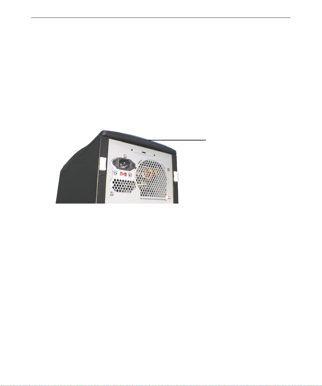
Page 15
AC Power Receptacle
AC Voltage Selection Switch
Mouse
Keyboard
USB
Serial (COM)
Parallel (LPT)
3
Serial (COM)
Video Out (typical)
Expansion Slots
SCSI
Ethernet Network
MIDI/Game
Audio Line Out
Audio Line In
Microphone
Page 16

4
Refer to the following table as needed when connecting cables to the base unit.
Cable From
To Port Icon
Monitor Video Out *
Keyboard PS/2 Keyboard
Mouse PS/2 Mouse
Serial peripheral device Serial (COM) 1 or 2
Parallel peripheral device Parallel (LPT)
Universal Serial Bus (USB) peripheral device Universal Serial Bus
Fast, Ultra, or Ultra2 SCSI peripheral device Wide Ultra2 SCSI *
Ethernet network Ethernet Network *
Speakers or headphones Audio Line Out *
External audio device Audio Line In *
Microphone Microphone *
Game joystick or MIDI device MIDI/Game *
* The port is on an expansion card installed in a slot at the back of the base unit. Ports on
expansion cards may not have icons.
To connect the system components:
1. Connect the video cable from the monitor to the video out port on the installed graphics
controller card. If the system has multiple monitors, connect one monitor to each installed
graphics controller card. See the graphics controller documentation for more information.
2. Connect the cables from the keyboard and the mouse to the appropriate ports.
3. Connect the cables from the speakers and (if available) a microphone to the appropriate ports
on the audio controller card. You may also need to connect the speakers to AC power; see the
speaker documentation for more information.
4. Connect a cable from your site’s Ethernet network to the port on the network controller card.
See the network controller card documentation for more information.
5. Connect a cable from a parallel peripheral device (such as a printer) to the parallel port.
6. Connect cables from serial peripheral devices (such as a modem) to the serial ports.
7. Connect cables from any USB peripheral devices to the USB ports.
8. Connect the cable from any external SCSI peripheral devices to the port on the SCSI
controller card. See “Connecting External SCSI Devices” in this chapter for more
information.
Page 17
9. Connect cables to ports on any other installed expansion cards as required. See the expansion
card documentation for more information.
CAUTION Do not connect the system power cord to the base unit or to an AC power outlet at
this time. See “Connecting to AC Power” later in this chapter for more information.
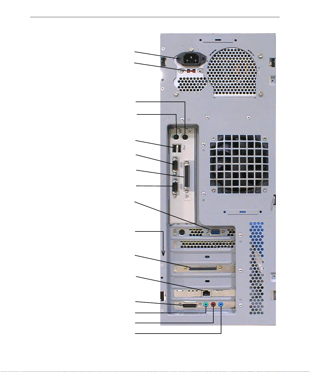
Locating Expansion Cards
Expansion cards are installed as needed in the Accelerated Graphics Port (AGP), Peripheral
Component Interconnect (PCI), and Industry Standard Architecture (ISA) expansion slots.
5
Slot 1 AGP
Slot 2 PCI
Slot 3 PCI
Slot 4 PCI
Slot 5 PCI
Slot 6 PCI or ISA
Slot 7 ISA
The following table describes the expansion slots and typical installed expansion cards:
Slot
Type Typical Expansion Cards Installed
1 (Top) AGP Graphics controller
2 PCI Graphics controller (for multi-card configurations)
3 PCI Graphics controller (for multi-card configurations)
4 PCI SCSI controller
5 PCI Audio controller
6 PCI or ISA Network controller; audio controller
7 (Bottom) ISA Audio controller
NOTE If a modem card used in the system receives ground from the system, ensure the
system is connected to an earth-grounded AC power outlet.
For information on installing or connecting to expansion cards, see Chapter 9, “Upgrading the
System,” and the expansion card documentation delivered with the system.
Page 18

6
Connecting External SCSI Devices
Your system has a single-channel Symbios 8952U low-voltage differential signaling (LVDS) Wide
Ultra2 SCSI controller card. The system’s internal SCSI devices connect to the card’s internal
connector. You can connect Fast, Ultra, or Ultra 2 SCSI devices to the card’s external port.
To ensure data integrity and promote optimum performance:
♦ The maximum speed of a SCSI bus is limited to the speed of the slowest device on that bus.
♦ Use the shortest cables possible to connect SCSI peripheral devices.
♦ Use high-quality SCSI cables to ensure adequate shielding (impedance of 110 to 135 ohms).
To connect external SCSI devices:
1. If the system is connected to AC power and operating, shut down the system and unplug the
system power cord from its AC power outlet.
SCSI Port
2. Connect one end of a SCSI cable to the SCSI port on the system.
3. Connect the other end of the SCSI cable to a SCSI peripheral device.
4. Connect a SCSI cable between SCSI ports on any additional SCSI peripheral devices.
5. Set the SCSI ID of each peripheral device to a unique
ID numbers already used by the system.
6. For each SCSI peripheral device connected to the port, if the device is:
− The last or only device on the SCSI chain, enable SCSI termination
− Not the last or only device on the SCSI chain, disable or remove SCSI termination
7. Ensure that the power switch on each peripheral device is in the off position; then connect the
power cord from each peripheral device to an AC power outlet.
8. Turn on power to all connected SCSI peripheral devices and then start the system.
9. If necessary, install software drivers and configure the peripheral devices according to the
vendor’s instructions.
Most SCSI controllers do not recognize a hard disk drive formatted using a different brand of
controller. You must use Symbios-formatted hard disk drives with a Symbios SCSI controller.
See Chapter 3, “Configuring the System,” for information on the SCSI Configuration Utility.
SCSI ID number. Do not use any SCSI
Page 19
If you want to boot the system from an external SCSI hard disk drive, ensure the SCSI controller to
which the boot drive is connected is installed lower in slot order than all other bootable SCSI
controllers and devices.
See Chapter 9, “Upgrading the System,” for additional details on installing external SCSI
peripheral devices.
Connecting to AC Power
CAUTION The AC power cord for this unit is the service disconnect. To remove AC power from
the system, you must unplug the system power cord from its AC power outlet.
CAUTION Ensure the AC power outlet to which the system’s power cord connects is close to
the system and is easily accessible
When you connect the system’s base unit to AC power, auxiliary power is applied to the system.
Auxiliary power ensures that system components power up quickly when needed. See Chapter 4,
“Operating the System,” for more information on controlling system power.
7
AC Power Receptacle
AC Voltage Selection Switch
To connect the system to AC power:
1. Make sure the AC voltage selection switch on the power supply (on the back of the base unit)
is set to the proper line voltage for your location.
− If your location uses 90 to 135 volts, the number 115 must be visible.
− If your location uses 180 to 264 volts, the number 230 must be visible.
WARNING If you do not set the AC voltage selection switch on the power supply correctly,
equipment damage may occur when you turn on power to the system.
2. Connect the system’s power cord to the AC power receptacle on the base unit.
3. Connect the power cords from the monitor, base unit, and any external peripheral devices to
properly grounded, three-prong AC power outlets.
Page 20
8
Starting the System
CAUTION If you start the system, and then turn it off before completing the instructions in
Chapter 2, “Setting Up the Software,” you will have to reinstall the operating system
and associated system software. See “What’s Next” for more information.
CAUTION Before starting the system for the first time, you may want to learn more about
system power, startup, and shutdown. See Chapter 4, “Operating the System,” for
more information.
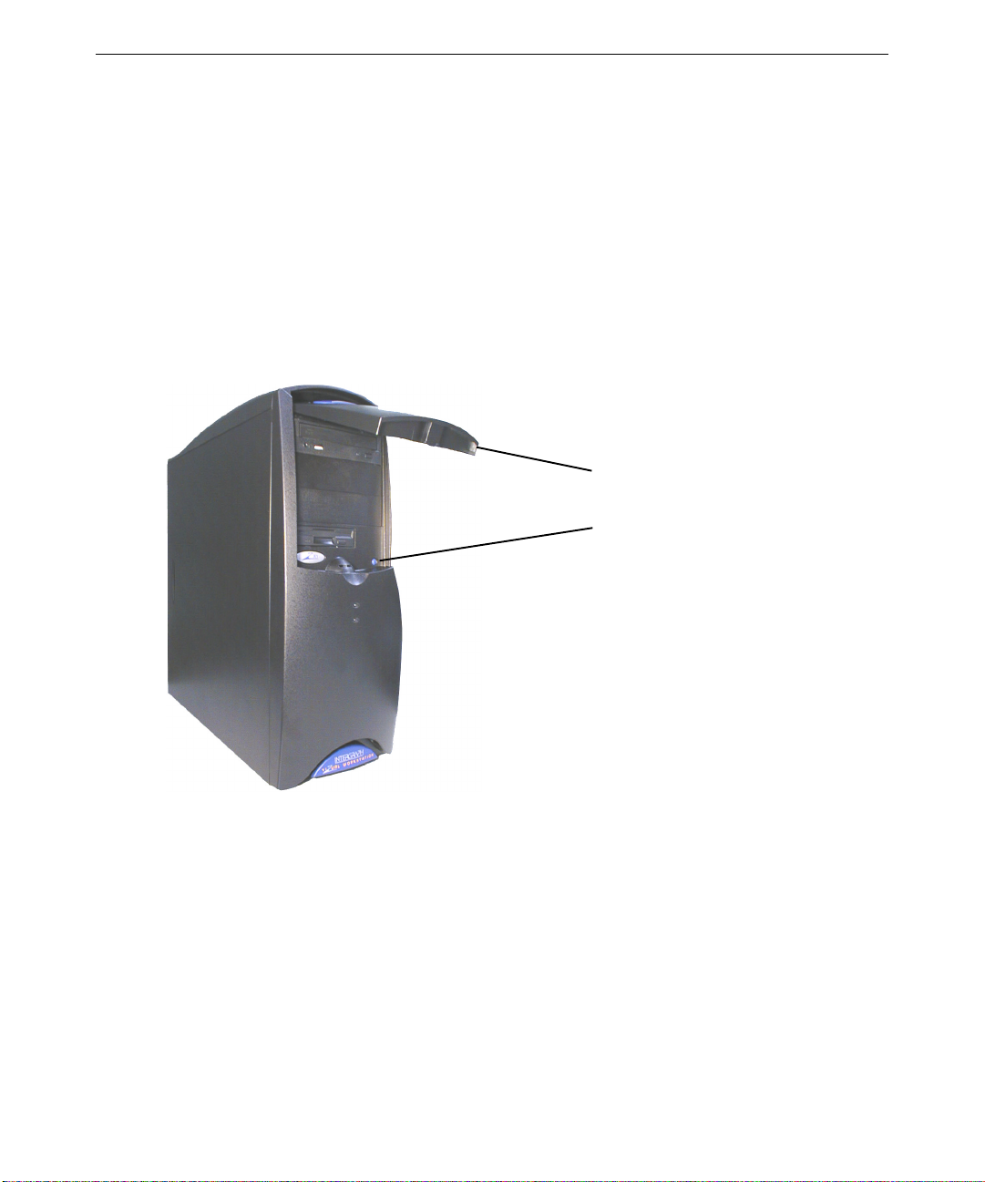
To start the system, open the door on the front of the base unit and press the Power button shown
in the following figure.
Door
Power Button
What’s Next?
You can do the following to prepare your system for use:
♦ If you want to get going with the default setup, go to Chapter 2, “Setting Up the Software,” to
start the system and go through o perating system Setup. If you st art the system and then
turn it off before completing operating system Setup, you will have to reinst all the
operating system and associated system software.
♦ The opera t i ng system is already installed thro ugh t he first phase of the Setup process. If you
want to reload the operating system and system software instead of completing Setup, see
Chapter 6, “Reinstalling the Operating System.”
Page 21

2 Setting Up the Software
This chapter describes how to set up the operating system and associated system software for your
Zx
1 workstation.
Preparing for Setup
Your system’s disk drives were formatted and partitioned before shipment. In Explorer or My
Computer, you can right-click a disk drive and click Properties to display the drive’s partition size
and file system format. See the operating system documentation and Help for more information on
these and other disk administration tools.
The operating system and associated system software is installed on the system’s primary hard disk
drive. Installed system software includes:
♦ Driver software for the SCSI controller, graphics controller, audio controller, network
controller, and mouse
♦ Driver software for internal peripheral devices and for additional expansion cards installed at
the factory
9
♦ Core networking software
♦ The latest certified operating system Service Pack software, if needed
♦ Quick-Fix Engineering (QFE) update software, if needed
♦ InterSite system management software
The operating system is installed through the first phase of the Setup process. You must follow the
Setup process to prepare the operating system for use.
Before you go through operating system Setup, have the following documents availabl e:
♦ Microsoft’s operating system documentation.
♦ Documentation for the system’s SCSI controller, graphics controller, network controller, and
any expansion card s you purchased.
♦ Intergraph Computer Systems’ Late-Breaking News document (if provided)
Page 22

10
Get and record the following information:
Your name, and the name of your company or
organization:
The Product Identification Number from
Microsoft’s documentation, Certificate of
Authenticity, or registration card:
A user name for a user account:
If the system is connected to a network, get and record the following information for your system
from your network administr ator:
Computer name:
Workgroup name (if the system will be part of
a workgroup):
Domain name (if the system will be part of a
domain):
If the system is connected to a network that uses the Transmission Control Protocol/Internet
Protocol (TCP/IP), get and record the appropriate TCP/IP information for your system from your
network administrator:
Internet Protocol (IP) address:
IP subnet mask:
IP domain name fo r your network:
IP addr ess for your network’s de fault gateway:
IP addresses for Domain Name System (DNS)
servers, if any:
IP addresses for Windows Internet Name
Service (WINS) servers, if any:
The operating system delivery media contain software and drivers for both Reduced Instruction Set
Computing (RISC)- and Intel-based systems. When installing operating system software, make
sure you install it from the \
I386 directory on the delivery media.
Page 23
Going Through Setup
CAUTION If you start the system and then turn it off before completing operating system Setup,
you will have to reinstall the operating system and associated system software.
CAUTION Before starting the system for the first time, you may want to learn more about
system power, startup, and shutdown. See Chapter 4, “Operating Notes,” for this
information.
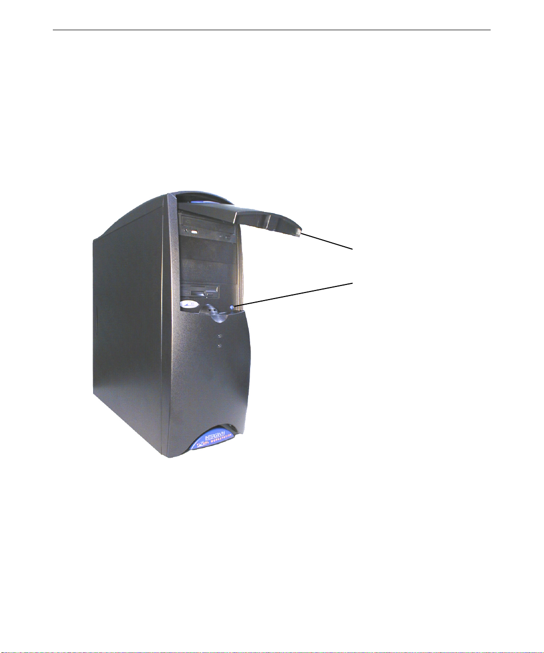
To start the system for the first time, press the Power button shown in the following figure.
11
Door
Power Button
The first time you start the system, it boots to a Microsoft End User License Agreement (EULA).
After reading and accepting the terms of the agreement, follow the instructions to continue
operating system Setup. Take the default settings provided by Setup, except as noted in the
following text. You can set up a user account and join a workgroup or domain after you configure
the system for use.
To start the computer and set up the operating system software:
1. Turn on power to the monitor.
2. Turn on power to the base unit. The system starts and the EULA displays.
Page 24

12
3. Read the terms of the EULA and then follow the instructions displayed to complete the Setup
process. When prompted, enter the Product Identification Number.
NOTE You must enter the Product Identification Number before you can continue Setup.
You cannot complete Setup if you do not enter this number.
4. Accept the default settings provided by Setup, except as noted in the following text.
When setting up the operating system software, remember the following:
♦ When prompted to create an Emergency Repair Disk, do so.
♦ If prompted to enter a password for the Administrator account, do so.
♦ If you do not create a user account during Setup, press
to log on to the operating system.
♦ You can use the C:\
Setup files. If you delete the
to an operating system CD-ROM to use the operating system’s Setup files.
After you complete Setup and restart the system, you can set up a user account and join a
workgroup or domain if needed. See the operating system documentation and operating system
Help for more information on Setup, creating a user account, and joining a workgroup or domain.
Finishing Setup
After operating system Setup completes, a Press to finish setup icon displays on the operating
system desktop. Double-click this icon, or go to Programs/InterSite/Welcome on the operating
system Start menu, to display InterSite Welcome.
InterSite Welcome helps you create a repair disk for the operating system, and create backup
diskettes of device driver software and other system software products. You can use InterSite
Welcome to get the latest driver and other system software from the World Wide Web, and to
learn more about customer support.
You should take advantage of the tools provided by InterSite Welcome to ensure that your system
is fully ready for use. See InterSite Welcome for more information. Also see the following
sections for information on creating a repair disk and creating backup diskettes.
ENTER or select OK at the logon dialog
I386 directory when prompted for the location of the operating system’s
I386 directory from the system’s hard disk, you must have access
Page 25

Creating an Emergency Repair Disk
If you did not create an Emergency Repair Disk during Setup, use the tools provided by InterSite
Welcome to do so. See the operating system documentation and Help for information on creating
an Emergency Repair Di sk. You should also update an Emergency Repair Disk after you finish
configuring the system.
In the event of corrupted disk drives, the files on the Emergency Repair Disk restore the contents
of the operating system registry at the time the operating system was installed, along with the
standard operating system drivers.
Creating System Software Backup Diskettes
CAUTION You must have system software backup diskettes available to reinstall critical system
software or the operating system if needed.
Backup diskettes for most device driver software and system software products are not delivered
with the system. Use InterSite Version Manager, available through InterSite Welcome, to create
system software backup diskettes.
Version Manager lets you create backup diskettes containing device driver software and system
software products that were installed on the system before shipment, and which are not available
on the operating system CD-ROM. You may need these backup diskettes later -- for example, if
you have to reinstall a device driver or the operating system.
13
You may not have to cre ate backup diskettes for all system software. If Version Manager does not
list a specific driver or other system software product, it is available on the operating system
software CD-ROM, or on backup diskettes or CD-ROMs delivered with expansion cards or
peripheral devices.
See Version Manager Help for information on creating system software backup diskettes. Visit the
support pages on the World Wide Web and vendor bulletin boards for new and updated drivers.
Creating a QFE Update Software Diskette
If the system requires Quick-Fix Engineering (QFE) update software, it is included in the system
software available for backup diskette creation. QFE update software contains fixes for operating
system problems or limitations, and is only shipped with the system if it is needed.
If QFE update software is shipped with the system, you should use Version Manager to create a
QFE update software diskette for use if you have to reinstall the operating system. See the
README.TXT file on the QFE diskette for information on the applicability and installation of QFE
update software on your system.
Page 26

14
What’s Next?
See Chapter 3, “Configuring the System,” to configure the system for use.
See Chapter 4, “Operating the System,” for related information on operating the system.
Page 27

3 Configuring the System
This chapter describes how to configure basic components of your Zx1 workstation for use.
Configuring the Video Display
The first time you start the system, your monitor displays a resolution of 1024 x 768. For the
system to use the installed graphics controller at other display resolutions, you must configure the
video display driver as described in this section.
From the operating system Start menu, go to Settings/Control Panel/Display to configure the video
display driver, or right-click an open space on the operating system desktop and click Properties in
the pop-up menu. In the Display Properties dialog, you can change the settings for color depth,
desktop size, font size, refresh rate, and display type of the system’s video display. You can also
determine which type of graphics controller is installed on your system.
15
See the graphics controller documentation delivered with the system, and any
delivered with the video display driver, for detailed configuration instructions. For information on
using the Display Properties dialog, see the operating system documentation and Help.
Resetting the Video Display Resolution
If the monitor connected to your system does not support a resolution of 1024 x 768, you can reset
the video display to another resolution.
To reset the video display resolution:
1. Restart the system.
2. At the boot screen, select the VGA mode option, and then log on to the operating system.
3. From the operating system Start menu, go to Settings/Control Panel/Display.
4. In the Display Properties dialog, select a resolution appropriate for your system's monitor.
5. Click Test to test the new video mode.
6. Restart the system if prompted to do so.
README files
Page 28

16
Changing the Default Video Display Driver
After configuring the video display and restarting the system, you may need to configure the
system to use the installed video display driver by default.
To change the default video display driver:
1. From the operating system Start menu, go to Settings/Control Panel/System.
2. Under Operating System, select the Startup list; then select the appropriate non-VGA option
from the displayed list, and click OK.
Correcting Initial Video Display Problems
If the system’s video display is black, not synchronized, or distorted after you restart the system,
you may have a video configuration problem. Do not press
to correct the problem by using the Last Known Good option to return the system to the last known
good configuration recorded by the operating system.
To use the Last Known Good option:
1. Power down and restart the system.
CTRL+ALT+DEL to log on. Instead, try
2. Press the space bar when prompted to display the Last Known Good menu.
If using the Last Known Good option fails to correct the video display problems, you can obtain a
functional video resolution by restarting the system in VGA mode.
To restart the system in VGA mode:
1. Power down and restart the system.
2. At the boot screen, select the VGA mode option.
After logging on in VGA mode, check for the following common problems and solutions:
♦ A multi-sync monitor is selected, but a graphics display device with different video timings is
connected to the system. Select a different monitor type.
♦ The monitor selection is incorrect. Select a different monitor type.
♦ There is not enough video disp lay memory to support the selected resolution and color depth.
Install and reconfigure the video display to use a lower resolution and color depth.
Restart the system and, when the boot screen displays, select the appropriate non-VGA version of
the operating system to use the reconfigured video display driver. If problems persist, contact the
Customer Response Center for help.
Page 29

Configuring System Audio
The system has a Sound Blaster-compatible audio controller card. This Industry Standard
Architecture (ISA) or Peripheral Component Interconnect (PCI) card contains the system’s audio
ports and MIDI/game port. The required driver software was installed before shipment.
If you connect a microphone and speakers to the ports on the card, you can use the operating
system’s Volume Control to set speaker volume, microphone input level, and other system audio
features. The Volume Control is available as a speaker icon in the operating system’s taskbar tray.
For more informatio n on using the sound control programs, see t he operating system
documentation and Help. For more information on the audio controller card, see the audio
controller documentation delivered with the system.
Configuring Networking
The system has a 3Com 3C905B-TX 10 Mbit/100 Mbit Ethernet network controller card. This
Peripheral Component Interconnect (PCI) card features Wake-On-LAN technology. The required
driver software was installed before shipment.
17
Before you configure networking, ensure that the system is connected to the network. Then from
the operating system Start menu, go to Settings/Cont rol Panel/Ne twork to configure networ ki ng.
Follow the instructions provided to set up the system to connect to and communicate over a
network. Be sure to set up the appropriate network protocols, such as TCP/IP, for the network to
which you are connecting the system.
After installing network protocols, you may need to reinstall the appropriate operating system
Service Pack software as recommended by Microsoft. See the Service Pack documentation
delivered with the system for more information.
See the network controller documentation for detailed configuration instructions. See the
operating system documentation and Help for information on setting up the operating system to use
a network.
Page 30

18
Configuring Peripheral Devices
If you install additional peripheral devices in the system—such as a modem, a Zip or Jaz drive, a
tape drive, or a CD-Recorder (CD-R) drive—you will have to install and configure the associated
driver software. You may also have to install or configure any associated application software to
use the devices.
See the documentation delivered with the peripheral devices for information on installing and
configuring driver software and associated application software. See the operating system
documentation and Help for information on using peripheral devices with the operating system.
Changing Drive Letters
If you have more than one hard disk drive or CD-ROM drive, you may need to reassign system
drive letters. See the operating system Help for more information.
To change drive letters:
1. Exit all applic ations currently running on your system.
2. From the operating system Start menu, go to Programs/Administrative Tools/Disk
Administrator.
3. Select a hard disk drive or the CD-ROM drive.
4. From the Tools menu, click Assign Drive Letter.
NOTE If you select the current drive or an otherwise locked drive, you must restart the
system to complete the drive letter reassignment.
5. Select a new drive letter to assign to the drive from the list. Click OK, and then click Yes to
continue.
6. If necessary, click OK, and then click Yes.
7. Repeat steps 2 through 6 for each drive letter assignment that you want to change.
8. Click Partition, then click Exit. If necessary, restart the system to complete the drive letter
reassignments.
Page 31

Changing Virtual Memory Settings
If you have more than one hard disk drive, you may need to change size and location of your
virtual memory page file. See operating system Help for more information.
Consider the following before changing page file setti ngs:
♦ The size of the page file. If your system is equipped with a large amount of RAM, Setup
might create a page file that is unnecessarily large.
♦ Drive letter reassignments. If you reassigned your drive letters, you may find it necessary to
adjust your page file settings.
To change the size and location of the virtual memory page file:
1. From the operating system Start menu, go to Settings/Control Panel/System/Performance.
2. Click Change.
3. Click a drive letter in the list, and then type new values in the Initial Size and Maximum Size
text boxes.
4. Click Set.
19
5. Repeat steps 3 and 4 for any additional drives in the list.
6. Click Close, and then click OK.
7. When prompted, click Yes to restart the system with the new settings, or click No to continue
with other tasks and use the new settings the next time you restart the system.
Configuring the SCSI Controller
The system has a Symbios 8952U SCSI controller card. This single-channel PCI Wide Ultra2
SCSI controller manages internal and external SCSI peripheral devices. You may need to use the
SCSI Configuration Utility (
connected to the controller. This utility lets you configure SCSI controllers, perform a low-level
format on a SCSI hard disk drive, select boot order, and verify media.
You may need to change SCSI controller parameters for a single SCSI peripheral device:
♦ If you are advised to do so by technical support or by the vendor documentation.
♦ If the SCSI device does not negotiate properly with the controller.
♦ If you exceed the maximum cable length for connecting SCSI devices to the system. See
Chapter 9, “Upgrading the System,” for more information.
♦ If you connect non-Ultra or non-Ultra2 SCSI external devices to the system.
PCI_CFG.EXE) to configure the operation of SCSI peripherals
Page 32

20
To run the SCSI Configuration Utility:
Press
CTRL+C when prompted during system boot.
When using the SCSI Configuration Utility, remember the following keyboard tips:
♦ Press the up or down arrow keys to move about in the menus.
♦ Press
See SCSI Configuration Utility Help for more information on using the utility.
ENTER to confirm a menu selection or ESC to cancel a selection.
Creating an Emergency Repair Disk
You should create an Emergency Repair Disk after you finish configuring the system. The files on
the Emergency Repair Disk can restore a damaged registry to its original contents (that is, at the
time the operating system was installed), along with the standard operating system drivers.
Use the
Software”) to create an Emergency Repair Disk. You can also use these utilities to update the
Emergency Repair Disk any time you change the system’s configuration. You should also make
and keep a backup copy of the Emergency Repair Disk.
See the operating system documentation and Help for information on creating and using an
Emergency Repair Disk.
RDISK.EXE utility or InterSite Welcome (as described in Chapter 2, “Setting Up the
Configuring the BIOS
The system’s basic input/output system (BIOS) reco rds basic system operating parameters, suc h a s
the amount of memory, the boot sequence, and the type of video display. The BIOS is stored in
flash-programmable memory, and reads the system parameters in the system’s complementary
metal-oxide semiconductor (CMOS) memory. When you power off the system, a battery provides
power to CMOS memory to retain the system parameters. Each time you power on the system, the
BIOS uses these stored parameters to configure the system for operation.
The BIOS Setup program, which is also stored in flash-programmable memory, allows you to
manually change the system operating parameters. You can run the BIOS Setup program as the
system boots, during the system’s power-on self-test (POST). For more information on the BIOS
Setup program and how to use it to configure the BIOS, see Chapter 7, “Configuring the BIOS.”
What’s Next?
See Chapter 4, “Operating the System,” for basic information on operating the system.
Page 33

4 Operating the System
This chapter contains important, basic information on operating your Zx1 workstation.
Opening and Closing the Door
A door on the front of the system controls access to the Power button, LED indicators, the floppy
disk drive, the CD-ROM drive, and other front-access peripheral devices.
21
To open the door:
1. Lift the bottom of the door to swing it up and away from the faceplate.
2. Push the door straight into the base unit.
Page 34

22
To close the door:
1. Pull the door straight out of the base unit.
2. Swing the door down until it clicks into place.
Controlling System Power
CAUTION The AC power cord for this unit is the service disconnect. To remove AC power from
the system, you must unplug the system power cord from its AC power outlet.
When you connect the system’s base unit to AC power, auxiliary power is applied to the system.
Auxiliary power ensures that system components power up quickly when needed.
The Power button is a momentary contact switch, changing system states based upon the length of
time the button is pressed. Depending on the system’s current power state, you can use the Power
button to start, shut down, and power down the system.
CAUTION Shut down the operating system before powering down the system. Simply pressing
the Power button can cause data corruption or loss. Use Automatic Shutdown or the
operating system’s shutdown options first. See this and following sections for more
information.
Page 35

23
Power Button
Power LED
Disk LED
Press the Power button… To…
Momentarily (less than 1 second) Bring the system to full power from a powered-down state
and start the operating system
Momentarily (less than 1 second) Start Automatic Shutdown to shut down the operating system
and power down the system
And hold it for at least 4 seconds Power down the system without using Automatic Shutdown
or after using the operating system’s shutdown functio n
See “Using Automatic Shutdown” for more information on controlling system power.
Reading System LEDs
The LEDs on the faceplate describe the current operational state of the system.
If the Power LED is…
Unlit Auxiliary power is off; there is no power consumption; the
Blinking Auxiliary power is on; power consumption is reduced
Lit The system has full power; power conservation is per device
If the Disk LED is…
Unlit The system’s disk drives are not active
Lit and blinking The system’s disk drives are active
Lit and unblinking There may be a problem with one or more disk drives
Then…
system is disconnected from AC power
Then…
Page 36

24
Using Automatic Shutdown
The Automatic Shutdown Utility contains more options for shutting down the system than the
operating system’s shutdown function. You can use this utility to shut down the operating system
and power down the system in a number of ways.
To run Automatic Shutdown:
♦ Double-click the Automatic Shutdown icon in the operating system’s taskbar tray…
♦ OR from the operating system Start menu, go to Programs/Automatic Shutdown Utility/
Automatic Shutdown Utility…
♦ OR while the system is running, press the Power button momentarily (less than 1 second).
By default, Automatic Shutdown is set for a 10-second delay. You can use the slider under Time
Remaining to set a delay of up to 30 seconds. Always set a delay greater than 5 seconds to ensure
that you have time to stop system shutdown if needed.
When you run Automatic Shutdown, the Auto matic System Shutdown dialog displays. To
configure Automatic Shutdown, choose an option in the dialog and click Apply. When you are
finished configuring the utility, click Start Shutdown. After you start the system again, the utility
will use the settings you selected.
The Automatic System Shutdown dialog contains the following options:
Options
Shutdown the Computer Performs an orderly shutdown of the operating system. When
Power Down the Computer Performs an orderly shutdown of the operating system, then
Shutdown System and Restart
the Computer
Close All Programs and Log
On as Different User
CAUTION You should use Power Down the Computer to power down the system. If you use
Shutdown the Computer, you must press and hold the Power button for 4 seconds to
power down the system. You may “suspend” the system if you hold the Power button
for less than 4 seconds. Since Windows NT does not support a Suspend mode, you
must then power down the computer before you can restart the system.
Description
complete, press the Power button for 4 seconds to power down
the system, or restart the operating system.
powers down the system.
Performs an orderly shutdown of the operating system, then
powers down and restarts the system.
Closes your logon to the operating system and returns to the
operating system logon prompt.
Page 37

The Automatic System Shutdown dialog also provides these functions:
25
Option
Description
Force All Processes to Terminate Terminates all programs if checked. If this option is not
checked the system displays an End Task dialog for each
process that may still be running.
Time Remaining Sets the time to delay before starting shutdown. When
Automatic Shutdown runs, this ti mer begins counting do wn.
Press Enter or click Stop Shutdown to stop the timer.
Stop Shutdown/Start Shutdown Stops or starts the shutdown timer. This button toggles
between Stop and Start.
See Automatic Shutdown Help for more information on this utility.
Starting and Stopping the Operating System
To start the operating system:
1. Turn on power to the system.
2. At the boot menu, select the appropriate operating system option, and then press
To log on to the operating system:
1. If the logon dialog does not display, press
2. If user accounts have been set up, type a user name and a password into the appropriate fields.
CTRL+ALT+DELETE to display it.
ENTER.
3. If appropriate, type a domain name into the appropriate field.
4. Select OK or press
ENTER.
To log off, restart, shut down, or power down the system:
1. Press the Power button momentarily (less than 1 second). Automatic Shutdown runs and the
shutdown timer begins co unt ing down.
2. Select a shutdown option and click Start Shutdown.
3. If you chose an option that requires you to power down the system manually, you can do so
when prompted that it is safe to do so.
For more information on starting and stopping the operating system, see the operating system
documentation and Help.
Page 38

26
Observing Operating Precautions
Observe the following precautions when operating the system:
♦ When restarting the system, use the operating system controls instead of turning the power
switch off and on. Use the power switch only when instructed, or as the last alternative for
restarting the system.
♦ Never turn off power to the base unit when the disk access LED is lit.
♦ After turning off power to the base unit, wait at least 30 seconds before turning the power on
again. This allows the power supply to stabilize and the disk drives to stop spinning.
Using the Keyboard
The system’s PS/2-compatible keyboard includes the following features:
♦ 104 standard keys, including special application function keys (
F1 through F12), arrow keys
for moving the cursor, and numeric ke ys in a keypad.
♦ Special keys for use with Wi ndows operating systems. Pressing the left or right Windows key
(on either side of the space bar) displays the operating system Start menu and Taskbar.
Pressing the Application key (to the right of the space bar) displays an application-specific
pop-up menu.
Numeric
Function
Keys
Keypad
Arrow
Keys
Application
Key
Windows
Keys
The keyboard delivered with the system may appear different from the one shown.
Page 39

Some keyboard keys have special functions, as follows:
27
Key
ESC Usually assigned to an application-specific function; often used to exit.
PRINT SCRN Depending on the application in use, prints the displayed screen to a printer.
SCROLL LOCK Prevents the screen from scrolling.
PAUSE Temporarily suspends screen scrolling or some operations.
CAPS LOCK Types all letters as capitals.
NUM LOCK Activates the numeric keypad.
CTRL Used with another key for application-specific functions.
ALT Used with another key for application-specific functions.
DELETE Deletes characters.
Function
You can use either of the Windows keys in combination with other keys to perform certain
operating system functions, as follows:
Key Combination
Action
Windows + F1 Display a pop-up menu for the selected object
Windows +
Windows +
Windows +
Windows +
Windows +
SHIFT + Windows +
Windows +
TAB Activate the next button on the taskbar
E Run Explorer
F Run Find Document
CTRL + F Run Find Computer
M Minimize all windows
M Restore all windows
R Display the Run dialog
Using the Mouse
The system’s PS/2-compatible mouse is a tracking device that controls the movement and
positioning of the pointer (or cursor) displayed on the screen in a graphical display environment.
Wheel
Buttons
Page 40
28
The mouse delivered with the system may appear different from the one shown.
To use the mouse, ensure it is connected to the system. Place the mouse on a clean, flat surface,
such as a desktop or a mouse pad. Rest your hand on the mouse, with a finger on each button and
the thumb to the side. Move the mouse across the flat surface to move the pointer on screen.
You can use the mouse to perform several actions:
Action
Point Move the mouse to point to your selection on the screen.
Click Press and release the left mouse button once.
Double-click Press and release the left mouse button twice.
Drag Press and hold the left mouse button, then move the mouse. Release the button
Right-click Press and release the right mouse button once.
Scroll On a wheel mouse, move the wheel back and forth to scroll in an application.
You can find more information on using the wheel mouse by right-clicking the mouse icon in the
taskbar tray, or by going to Start/Settings/Control Panel/Mouse and clicking Help in the toolbar.
Description
when you finish dragging your selection to a new location.
Using the Floppy Disk Drive
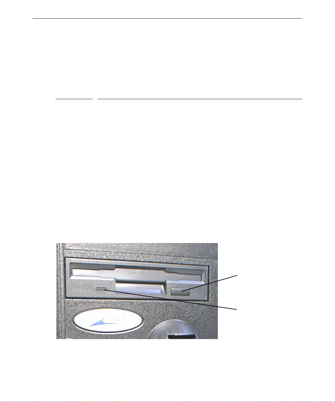
The system’s floppy disk drive occupies a 3.5-inch external peripheral device bay, and is
accessible through a 3.5-inch slot on the front of the base unit. The drive accepts standard 3.5-inch
720 KB and 1.44 MB diskettes.
Eject Button
Drive LED
Page 41

Follow these guidelines to use the floppy disk drive:
Drive LED
Eject Button
♦ To insert a diskette into the drive, position the diskette so the arrow embossed on the diskette
faces up. Slide the diskette into the floppy disk slot, and push it into the drive until it clicks
into place and the eject button next to the slot pops out.
♦ Before removing a diskette, ensure the drive LED is not lit. The LED lights green to indicate
floppy disk drive activity.
♦ Remove the diskette by pushing the eject button adjacent to the floppy disk slot, and then
pulling the diskette out of the drive.
♦ To protect the data on a diskette from being overwritten or erased, slide the write-protect tab
on the diskette toward the diskette edge until it snaps into place. To write data to a diskette,
ensure the write-protect opening is covered.
Using the CD-ROM Drive
The system’s CD-ROM drive occupies a 5.25-inch external peripheral device bay, and is
accessible through a tray or a slot at the front of the base unit. The drive supports software
ejection of discs and has an external amplified headphone jack.
29
Headphones
Volume Control
To use the CD-ROM drive:
♦ To insert a disc into a tray-load CD-ROM drive, press the eject button to extend the tray.
Place the disc, printed side up, in the tray and press the eject button to load the disc.
♦ To insert a disc into a slot-load CD-ROM drive, insert the disc, printed side up, into the slot.
Page 42

30
♦ To eject a disc from the CD-ROM drive, press the eject button adjacent to the CD-ROM drive
slot or tray. If the software application being used prevents the disc from ejecting, run the
proper application command to eject the disc.
♦ The media player programs included with the operating system allow you to listen to audio
compact discs. Insert an audio compact disc, printed side up, into the CD-ROM drive and
start the media player application. Adjust the volume using the operating system’s sound
control programs.
♦ You can connect headphones to the headphone port on the CD-ROM drive. Adjust the
volume using the volume control on the drive.
Learning About the Operating System
Documentation delivered with your system describes the basic functions of its operating system.
Refer to this documentation if you are unfamiliar with the operating system interface and features.
You can also refer to extensive online Help; from the operating system Start menu, go to Help.
Using InterSite Programs
Depending on its configuration, your system shipped with some or all of the following InterSite
programs installed:
♦ InterSite Welcome provides tools to ensure that your system is fully ready for use. See
InterSite Welcome for more information.
♦ InterSite Version Manager is a tool for creating system software backup diskettes, and for
updating device drivers and other system software products installed on the system.
♦ InterSite Watchdog is a system-monitoring tool with remote monitoring capabilities. You can
use it to monitor ot her workstations and ser vers also running Wind ows NT.
♦ InterSite Hardware Monitor is an easy-to-use interface to instrumentation data measured by
sensors inside the computer. Event information is reported to the Windows NT Event Log and
displayed graphically.
♦ InterSite DMI Console gives easy access to the system’s status and configuration information.
DMI Console works with the Desktop Management Interface (DMI), a technology standard
that enables the effective management of computers.
♦ InterSite SMART Disk Driver is a kernel-level driver that supports self-monitoring, analysis,
and repor ting technology (SMART).
♦ InterSite Diskeeper Lite helps you keep disk fragmentation to a minimum, improving file
creation and access times and system performance.
Page 43

From the operating system Start menu, go to Programs/InterSite to find the InterSite programs on
your system. See the online Help for each InterSite program for more information on how to use
the program.
Booting from System Drives
The primary system disk drive, which contains the operating system, is a SCSI disk drive. By
default, because the system contains both SCSI disk drives and an ATAPI CD-ROM drive, it
attempts to boot from the CD-ROM drive first. This is because the BIOS looks for a diskette, then
for an IDE boot drive, and then for the CD-ROM drive, before it looks for a SCSI disk drive.
Because of this default behavior, you should not restart the system with a bootable CD-ROM in the
CD-ROM drive. One example of a bootable CD-ROM is the operating system’s software
CD-ROM.
If you want, you can change the system’s boot device order in the BIOS. You can set the system to
boot first from a diskette, then from a SCSI disk drive, and then from the ATAPI CD-ROM drive.
See Chapter 7, “Configuring the BIOS,” for information on using the BIOS Setup program to do
this.
31
Finding the Serial Number
The system’s serial number is on a label affixed to the rear of the base unit.
Cleaning System Components
Follow these guidelines for cleaning system components:
Item
Exterior Surfaces Wipe exterior surfaces of the base unit and the monitor screen with a soft
Keyboard Dust the keys and the keyboard surface with a soft, dry cloth. Use an aerosol
Mouse Remove the retaining ring and the tracking ball from the bottom of the
How To Clean
cloth lightly moistened with a mild cleaning agent.
cleaner to remove dust and debris from between the keys. Do not use liquids
to clean the keys or the keyboard surface.
mouse. Blow gently into the opening. Wipe the tracking ball and the rollers
in the opening with a cotton swab moistened with alcohol. Replace the
tracking ball and the retaining ring.
Page 44

32
Page 45

5 Troubleshooting Operational Problems
Use this chapter to identify and resolve some common basic system problems.
Getting Started
If your system is not functioning properly, first do the following:
♦ Verify the system’s power state and ensure the system is properly connected to AC power.
See Chapter 1, “Setting Up the Hardware,” and Chapter 4, “Operating the System.”
♦ Ensure the data and power cables are properly connected to any external peripheral devices.
♦ Ensure the data and power cables are properly connected to all internal peripheral devices.
If you cannot resolve the problem or if the instructions in the following sections direct you to do
so, contact Intergraph Computer Systems for further help. See the Preface of this document for
information about contacting Intergraph Computer Systems. Refer to the documentation delivered
with various peripheral devices for troubleshooting help if there are problems these devices.
The following chapters in this document contain information and instructions that may be helpful
when carrying out troubleshooting procedures and attempting to apply solutions.
33
System Power
Fails to power on
Reason
System is not at full power, but is at
auxiliary power (Power LED blinks).
System will not awaken from
“suspend” state.
Power cord is not connected. Verify the power cord is connected to the power
Power is not available at the AC
power outlet.
Internal power cables are not
connected.
Power cord is faulty. Replace power cord.
Solution
Press the Power switch momentarily (less than 1 second)
to attempt to apply full power (Power LED lights).
Verify that Automatic Shutdown Utility (
installed. If not, turn system power off and then on again.
If so, use the Power Down the Computer option. See
Chapter 4 and Chapter 6.
receptacle.
Verify power is available at the AC power outlet. Test
the outlet with a known working device.
Open the base unit and ensure all power cables are
connected.
SHUTDOWN) is
Page 46

34
System Boot
Does not boot from the expected boot device
Reason
Boot device order is not correctly set. Change the boot device order in the BIOS. See
Operating system is not on the system
drive.
BIOS attempts to boot from wrong hard
disk drive.
IDE hard disk drive is connected to IDE
controller.
System attempts to boot from CD-ROM
drive instead of a SCSI hard disk drive.
Series of beeps and error messages display
Message
Refresh Failure Bad memory refresh circuitry on the system board.
Parity Error Parity error in the first 64 KB block of memory.
Base 64 KB Memory Error Memory failure in the first 64 KB. Remove and
Timer Not Operational Memory failure in the first 64 KB, or Timer 1 on
Processor Error The CPU on the system board generated an error.
8042 - Gate A20 Failure The BIOS cannot switch to protected mode. Call
Processor Exception Interrupt The CPU generated an exception interrupt. Call the
Solution
Chapter 7.
Reinstall the operating system.
Ensure SCSI controller for primary system disk
drive is installed lower in slot order than any other
SCSI controllers.
BIOS cannot boot from SCSI hard disk drive if an
IDE hard disk drive is connected. Disconnect all
IDE hard disk drives.
Do not boot the system with a bootable CD-ROM
disc in the CD-ROM drive. You may want to
change the boot device order in the BIOS to boot
from a SCSI disk drive first. See Chapter 7.
Explanation and Solution
Remove and reinstall DIMM(s). If error persists,
replace the DIMM(s).
Remove and reinstall DIMM(s). If error persists,
replace DIMM(s).
reinstall the DIMM(s). If error persists, replace the
DIMM(s).
the system board is not functioning. Call the
Customer Response Center.
Call the Customer Response Center.
the Customer Response Center.
Customer Response Center.
Page 47

Message Explanation and Solution
Display Memory Read/Write Error The sound controller is faulty. Call the Customer
Response Center.
ROM Checksum Error The ROM checksum value does not match the value
encoded in the BIOS. Call the Customer Response
Center.
CMOS Shutdown Register Read/Write
Error
The shutdown register for CMOS RAM failed. Call
the Customer Response Center.
Cache Error/External Cache Bad The external cache is faulty. Call the Customer
Response Center.
Does not boot from drive A (floppy disk drive) or other expected boot device
35
Reason
Boot disk is corrupt or does not have the
correct boot utilities.
Boot sequence may be set to C, A, in which
case the machine will not boot from A if there
is an operating system on C.
Solution
Replace the bootable diskette with a known
working diskette.
Change the boot sequence. See Chapter 7 for
information on running BIOS Setup and
changing the boot sequence.
BIOS is corrupted. Load a new BIOS to the system’s flash
memory. See Chapter 7 and the System Board
Manual.
Floppy disk drive is not recognized
Reason
Solution
BIOS is not configured properly. Reconfigure the floppy disk drive parameters in BIOS Setup.
See Chapter 7 for information o n running BIOS Setup and
changing the boot sequence.
Power cable is not connected. Open the base unit and ensure the power cable is connected.
Data cable is not connected. Open the base unit and ensure the data cable is connected.
System hard disk drive is not recognized
Reason
Solution
Power cable is not connected. Open the base unit and ensure the power cable is
connected.
Data cable is not connected. Open the base unit and ensure the data cable is
connected.
SCSI termination is enabled on the hard disk
drive you installed.
Disable SCSI termination. See the documentation
delivered with the hard disk drive.
Page 48

36
Reason Solution
Some viruses cause the system to not
recognize hard disk drives.
CD-ROM drive is not recognized
Run a virus scan program that checks the Master
Boot Record. Clear any viruses detected by the
program.
Video
Reason
Power cable is not connected. Open the base unit and ensure the power cable is
Data cable is not connected. Open the base unit and ensure the data cable is
Total amount of memory does not display
Reason
One or more memory modules are faulty. Identify faulty memory modules by swapping
Memory modules are not properly seated
in their sockets.
I/O Card parity error message displays
Reason
Faulty card is installed in the ISA slot. Remove the ISA card and then restart the system.
System is powered on, but screen remains blank
Reason
Monitor is not powered on. Turn on power to the monitor.
Power cord is not connected. Verify the power cord is connected to the power
Video cable not properly connected. Verify the video cable is connected to the monitor
Graphics card is not properly seated in its
socket.
Selected resolution is not supported by the
monitor.
An improper video display driver is
installed.
Solution
connected.
connected.
Solution
modules until the faulty one is found.
Reseat memory modules in their sockets.
Solution
Solution
receptacle.
and to the system’s video out connector.
Open the base unit and reseat the graphics card.
Select a supported resolution. See the graphics card
documentation for more information.
Install a valid video display driver. See the graphics
card documentation for more information.
Page 49

Audio
No sound can be heard
37
Reason
Speaker volume is low or off. Adjust speaker volume up.
Speaker cable is not properly connected. Verify speaker cables are connected to the
Volume is turned off in the software volume
control or mixer program.
Headphones a re plugged into t he system. Unplug the hea dphones.
Network
Cannot connect to other systems on LAN
Reason
Ethernet cable is disconnected. Verify the Ethernet cable is connected. If the cable is
Networking software is configured
incorrectly.
Cannot plot to network printer or plotter on LAN
Reason
Network cable is disconnected. Verify the network cable is connected.
Printer or plotter is not added to your system. Add the printer using the operating system tools,
Plot node does not recognize your system. Notify your network administrator.
Solution
system’s line out port.
Open the software volume control or mixer
program and turn up the volume.
Solution
properly connected, noti fy your ne t wor k administrator.
Review the network settings in the operating system, and/or
notify your network administra tor.
Solution
and/or notify your ne t work administrator.
Peripheral Drive Errors
CD-ROM drive LED does not light when system power is on
Reason
Power cable or data cable is not connected. Open the base unit and ensure the power cable
Solution
and data cable are properly connected.
Page 50

38
Floppy disk drive LED does not light when system power is on
Reason
Power cable or data cable is not connected. Open the base unit and ensure the power cable and
Miscellaneous Hardware
“Battery voltage low” message displays
Reason
Lithium battery voltage on the system board
is low.
System loses BIOS configuration information
Reason
Lithium battery voltage on the system board is
low. The system also displays a "battery voltage
low" message during the system boot.
DMA bus timeout message displays
Reason
Failure in DMA bus logic has occurred. Call the Customer Response Center.
Solution
data cable are properly connected.
Solution
Replace the lithium battery on the system board.
Solution
Replace the lithium battery on the system
board.
Solution
“Invalid configuration information for SLOT XX” message displays
Reason
System is not properly configured to recognize
the new ISA card.
Solution
Use BIOS Setup to reserve system resources
for the ISA card. See Chapter 7.
Page 51

6 Reinstalling the Operating System
This chapter provides basic instructions for reinstalling the operating system and associated system
software on your Zx
understand the entire chapter.
Before You Begin
Before you attempt to reinstall the operating system, have the following items available:
♦ Information about your system that you recorded in Chapter 2, “Setting Up the Software.”
♦ Microsoft’s operating system software CD-ROM, Service Pack CD-ROM, and associated
diskettes. Make sure you have any operating system Setup diskettes delivered with the
system.
♦ Microsoft’s operating system documentation.
♦ Backup diskettes you created in Chapter 2, “Setting Up the Software.” If you did not create
backup diskettes as directed in Chapter 2, you can still create them by using InterSite Version
Manager. Insert the Intergraph System CD delivered with your system into any computer
running Windows 2000, Windows NT 4.0, Windows 98, or Windows 95 and run Version
Manager. Create backup diskettes for the system software listed for your system in Version
Manager.
1 workstation. Before you attempt to reinstall the system software, read and
39
♦ Backup diskettes or software CD-ROMs and documentation delivered with any expansion
cards or additional peripheral devices you purchased with the system.
♦ The Late-Breaking News document delivered with the system, if applicable.
Finding System Software Products
Most driver software and other system software products installed on your system are available on
the Intergraph System CD delivered with the system. If a system software product is not available
there, you can find it in one the following locations:
♦ Microsoft’s operating system software CD-ROM.
♦ Diskettes or software CD-ROMs delivered with expansion cards or peripheral devices.
♦ Intergraph Computer Systems’ online services (see this document’s Preface).
CAUTION You must install certain drivers from backup or other diskettes. The correct driver
versions may not be on the operating system CD-ROM. If a driver version is
delivered on backup diskette or in Version Manager, that version should be used
instead of what is available on the operating system CD-ROM.
Page 52

40
Driver software is routinely improved and updated. Use InterSite Version Manager, or visit
Intergraph Computer Systems on the World Wide Web, to locate and download updated driver
software.
Installing the Operating System
Depending on your system’s configuration, you will need some or all of the following system
software during the installation process:
♦ SCSI controller driver
♦ Graphics controller driver
♦ Audio controller driver
♦ Network controller driver
♦ Mouse driver
To install the operating system software, follow the instructions in Microsoft’s documentation for
your workstation’s operating system. See the following text for information that you may need to
complete operating system Setup.
Do the following during installation of the operating system:
♦ When prompted to select a Setup type, select Custom Setup.
♦ On a system with internal SCSI disk drives and a SCSI controller, press the S key to install the
SCSI controller driver from backup diskette. Select Other (Requires disk provided
by a hardware manufacturer) from the list and press
the SCSI controller driver into the floppy disk drive, and then press
♦ Specify a driver for the CD-ROM drive by pressing the S key and then selecting IDE CD-ROM
(ATAPI 1.2)/ PCI IDE Controller from the list.
♦ On single-processor systems, when prompted, selec t Standard PC. This will load the
single-processor kernel and HAL, providing better performance.
On dual-processor systems, if prompted, select MPS Multiprocessor. This will load the
multi-processor kernel and HAL, enabling the system to take advantage of the second
processor.
♦ Allow Setup to configure the network only if you have an installed network controller, and
only if the system is connected to the network.
♦ When prompted, create an Emergency Repair Disk.
ENTER. Insert the diskette with
ENTER.
Page 53

Do the following after installation of the operating system:
♦ Install drivers or ot her system software from any backup diskettes. System software delivered
on backup diskette is usually more current than system software on the operating system
CD-ROM. Alternatively, you can install the drivers or other system software from the
operating system software CD -ROM if you do not have the m on diskette.
♦ Be sure to reinstall the Automatic Shutdown Utility, which is available as backup media
(
SHUTDOWN) in InterSite Version Manager. If you do not, pressing the system’s Power button
momentarily will put the system in a “suspend” state from which it will not awaken. You will
have to turn system power off and on to return to normal operation.
♦ Perform any additional installation and configuration tasks described in the Late-Breaking
News document delivered with your system.
♦ Configure the system as described in Chapter 3, “Configuring the System.”
♦ Perform any operational changes required for your system as described in Chapter 4,
“Operating the System.”
♦ If your system was running 4.0 Service Pack software, install this software afte r installing
drivers and other system software, and after installing any application software products.
Do the following after you install Service Pack software:
41
♦ If you created a Quick-Fix Engineering ( QFE_NT*) bac kup diskette from Version Manager
during any previous initial system configuration, install the QFE update software. See the
README.TXT file on the QFE diskette for more information.
♦ On a system with Pentium III processors, install Intel’s Streaming SIMD Extension Driver.
This driver increases system performance for drivers and applications designed to take
advantage of it. If this driver is not available as backup media (
Manager, you can get it from the Support pages on the World Wide Web
(http://www.intergraph.com/ics). See the
information.
Installing the Audio Controller Driver
To install the driver for the audio controller, follow the instructions found in the README.TXT file
delivered with the driver.
QFE_SSE) in InterSite Version
README.TXT file delivered with QFE_SSE for more
Page 54

42
Enabling Bus Mastering for IDE/ATAPI Devices
Your system shipped with bus mastering for IDE/ATAPI devices enabled. If you reinstall
Windows NT 4.0 and Service Pack software, you must re-enable IDE/ATAPI bus mastering.
NOTE If you install a CD-Recorder (CD-R) drive, do not enable IDE/ATAPI bus mastering.
The CD-R drive is incompatible with IDE/ATAPI bus mastering.
NOTE The QFE update software includes an updated ATAPI device driver that should be
installed after the Service Pack software.
NOTE For reasons of system performance, if you install a TR-4i tape drive or a Zip drive, do
not enable DMA use on the IDE channel to which the drive is connected.
To enable IDE/ATAPI bus mastering:
1. Ensure that the operating system, Service Pack software, and QFE update software (
are installed.
2. Insert the Windows NT 4.0 Service Pack CD-ROM into your system’s CD-ROM drive.
3. In Explorer or File Manager, go to the \
4. Double-click
DMACHECK.EXE. The ATAPI DMA support dialog displays.
SUPPORT\UTILS\I386 directory.
5. The Current DMA Usage boxes indicate which channels have IDE/ATAPI devices. For each
channel with an IDE/ATAPI device, click Enabled; then click OK.
6. Restart the system.
Updating the Operating System
Microsoft Service Packs and Service Releases contain the latest improvements and system fixes for
Microsoft operating systems. Service Packs and Releases are created by Microsoft for post-release
support. You can obtain them from Microsoft’s World Wide Web and FTP sites free of charge.
CAUTION If a Service Pack is posted to Intergraph Computer Systems’ online services, it has
been certified for use as described in the announcement of its availability. If you
obtain a Service Pack from any other source, be aware that it may not be certified
against your hardware.
QFE_NT*)
Page 55

7 Configuring the BIOS
This chapter provides basic information on configuring the system’s basic input/output system
(BIOS). Refer to this chapter for specific BIOS parameter settings for your Zx
more information on the various parameters and settings, refer to the System Board Manual.
BIOS Overview
The system’s basic input/output system (BIOS) reco rds basic system operating parameters, suc h a s
the amount of memory, the boot sequence, and the type of video display. The BIOS is stored in
flash erasable-programmable memory (EPROM) on the system board, and reads the system
parameters in the system’s complementary metal-oxide semiconductor (CMOS) random-access
memory (RAM). When you power off the system, a lithium battery provides power to CMOS
RAM to retain the operating parameters. Each time you power on the system, the BIOS uses
stored parameters to configure system operation.
The BIOS Setup program, which is also stored in the flash EPROM on the system board, allows
you to manually change the system operat ing parameters. You can also run the BIOS Setup
program during the system’s power-on self-test (POST). For the system to operate correctly, you
should run BIOS Setup after you make any hardware changes to the system.
43
1 workstation. For
Using BIOS Setup
To run BIOS Setup:
Press
DELETE when prompted during system boot.
To navigate BIOS Setup menus and parameters:
♦ Press
♦ Press
♦ Press
The initial BIOS Setup screen lists menus, general setup options, and exit options. The rest of this
chapter provides basic information on the contents of the menus and the functions of the options.
TAB or an arrow key to move from one field to the next.
ENTER to enter a menu or to run one of the general setup options.
PAGE UP or PAGE DOWN to change the setting of a parameter.
Page 56

44
General Setup Options and Exit Options
These general setup options and exit options are listed on the initial BIOS Setup screen.
Option
Auto-Detect Hard Disks Detects hard disk drives attached to each IDE channel and sets
Change Supervisor
Password
Change User Password Lets you set a password that limits changes to specific BIOS
Auto Configuration with
Optimal Settings
Auto Configuration with
Fail-Safe Settings
Save Settings and Exit Lets you save changes made to BIOS parameters and exit from
Exit Without Saving Lets you exit from BIOS Setup without saving changes to BIOS
Standard CMOS Setup
Parameter Description
Date, Time Sets the system date and time.
Floppy Drive A:, B: Sets the type of floppy disk drive(s) installed in your system.
Pri/Sec Master/Slave Set to Auto to let the BIOS automatically configure the
Boot Sector Virus Protection Sets virus protection for the boot sector of the system drive.
Description
their parameters automatically.
Lets you set a password that limits changes to specific BIOS
parameters to those made by the Supervisor.
parameters to those made by an authorized User (or Supervisor).
Lets you restore Optimal default values to all parameters. Optimal
defaults provide optimum performance settings for all devices and
system functions.
Lets you restore Fail-Safe default values to all parameters. FailSafe defaults are the safest set of parameters. They should always
work, but do not provide optimal system performance. Use them if
the system is behaving erratically.
BIOS Setup.
parameters.
The standard floppy disk drive is 1.44 MB 3½ inch.
device, choose a drive type, or manually configure drive
parameters such as drive type, drive size, number of
cylinders, number of heads, block addressing, and transfer
speed.
The Optimal default is Disabled.
Page 57

Advanced CMOS Setup
Parameter Description
Quick Boot Sets whether to boot the system quickly, bypassing some
Pri/Sec Master/Slave ARMD
Emulated as
st
1
, 2nd, 3rd Boot Device Sets the type of device for the first, second, and third boot
Try Other Boot Devices Sets whether the BIOS should try to boot from another
Initial Display Mode Sets initial display of BIOS information during boot. The
Floppy Access Control Sets diskette access when booting from diskette. The
Hard Disk Access Control Sets disk access when booting from a hard disk drive. The
SMART For Hard Disks Sets whether the BIOS uses the System Management and
BootUp Num Lock Sets the keyboard’s numeric keypad to numeric operation
PS/2 Mouse Support Sets BIOS support for a PS/2-type mouse. The Optimal
Primary Display Sets the type of monitor attached to the computer. The
Password Check Sets password checking when the system boots and BIOS
Boot To OS/2 Sets BIOS support for the OS/2 operating system and more
Internal Cache Sets the caching algorithm used by the Level 1 internal
memory testing and drive initialization. The Optimal
default is Enabled and the Fail-Safe default is Disabled.
Sets how the system should detect an ATAPI Removable
Media Disk (ARMD) attached as a master or slave device.
The Optimal default is Auto.
drives the BIOS attempts to boot after power-on self-test
(POST) completes. The Optimal default for 1
Device is Floppy. The Optimal default for 2
st
is 1
IDE-HDD. The Optimal default for 3rd Boot Device is
st
Boot
nd
Boot Device
ATAPI CD-ROM.
device if it cannot find the selected first, second, or third
boot devices. The Optimal default is Yes.
Optimal default is Silent.
Optimal default is Read-Write.
Optimal default is Read-Write.
Reporting Technologies (SMART) protocol for hard disk
drives. The Optimal default is Enabled.
(On) or functional operation (Off). The default is On.
default is Enabled.
Optimal default is VGA/EGA.
Setup runs. The Optimal default is Setup.
than 64 MB of system memory. The Optimal default is No.
cache memory on the processor. The Optimal default is
WriteBack.
45
Page 58

46
Parameter Description
System BIOS Cacheable Sets whether the contents of the F0000h system memory
Cache Bus ECC Sets ECC error checking on the Level 2 cache bus. The
Processor Serial Number Sets access to the Pentium III processor’s serial number.
Default Primary Video Sets which video card in a multi-video card system is the
MPS Revision Sets the Multi-Processor Symmetry version. The Optimal
C000/C400,16K Shadow Sets the use of the 32 KB of video ROM at C0000h and
C800/CC00/Dn00,16K Shadow Sets shadowing of the contents of the ROM area named in
Advanced Chipset Setup
segment are read from and written to cache memory. The
Optimal default is Enabled.
Optimal default is Enabled.
The default is Disabled.
primary video display. The Optimal default setting is PCI.
default is 1.1.
C400h. The Optimal default is Cached.
the parameter. The Optimal default is Disabled.
Parameter Description
USB Function Set support for the Universal Serial Bus (USB). The
Optimal default is Disabled.
USB KB/Mouse Legacy Support Sets support for older keyboards and mouse devices. The
Optimal default is Disabled.
Port 64/60 Emulation Sets support for a USB keyboard to act like a legacy
keyboard. The Optimal default is Disabled.
SERR# Sets support for the SERR# signal on the bus. The Optimal
default is Disabled.
PERR# Sets support for the PERR# signal on the bus. The Optimal
default is Disabled.
WSC# Handshake Sets handshaking for the WSC# signal on the bus. The
Optimal default is Enabled.
USWC Write Post Sets support to allow write operations from USWC memory
(used by VGA devices) to be posted. The Optimal default
is Enabled.
Master Latency Timer Sets the master latency timing for system devices. The
Optimal default is 64.
Multi-Trans Timer Sets the multi-trans latency timing for system devices. The
Optimal default is 32.
Page 59

47
Parameter Description
PCI1 to PCI0 Access Sets access between two different PCI buses. The Optimal
default is Disabled.
Method of Memory Detection Sets how the system detects system memory. The Optimal
default is Auto & SPD.
DRAM Integrity Mode Sets the type of memory checking. The Optimal default is
ECC Hardware.
DRAM Refresh Rate Sets the interval between refresh signals to DRAM system
memory. The Optimal default is 15.6 us.
Memory Hole Sets the area of memory that cannot be addressed on the
ISA bus. The Optimal default is Disabled.
SDRAM RAS# to CAS# delay Sets the delay between RAS# and CAS# signals for
SDRAM memory. The Optimal default is 3 SCLKs.
SDRAM RAS# Precharge Sets the length of RAS# precharge for SDRAM memory.
The Optimal default is 3 SCLKs.
Power Down SDRAM Sets support for SDRAM memory power-down. The
Optimal default is Enabled.
ACPI Control Register Sets support for the Advanced Configuration and Power
Interface (ACPI) control register. The Optimal default is
Disabled.
Gated Clock Sets support for the gated clock. The Optimal default is
Disabled.
Graphics Aperture Size Sets the amount of system memory that can be used by the
Accelerated Graphics Port (AGP). The Optimal default is
64 MB.
Search for MDA Resources Sets a BIOS search for MDA resources. The Optimal
default is Yes.
AGP Multi-Trans Timer Sets the AGP multi-trans timer. The Optimal default is 32.
AGP Low-Priority Timer Sets the AGP low-priority timer. The Optimal default is 16.
AGP SERR Sets support for the AGP SERR signal. The Optimal
default is Disabled.
AGP Parity Error Response Sets support for AGP parity error response. The Optimal
default is Disabled.
8bit I/O Recovery Time Sets the delay between consecutive 8-bit I/O operations.
The Optimal default is Disabled.
16bit I/O Recovery Time Sets the delay between consecutive 16-bit I/O operations.
The Optimal default is Disabled.
PIIX4 SERR# Sets support for the SERR# signal for the Intel PIIX4 chip.
The Optimal default is Disabled.
Page 60

48
Parameter Description
USB Passive Release Sets passive release for the USB. The Optimal default is
Enabled.
PIIX4 Passive Release Sets passive release for the Intel PIIX4 chip. The Optimal
default is Enabled.
PIIX4 Delayed Transaction Sets delayed transactions for the Intel PIIX4 chip. The
Optimal default is Disabled.
TypeF DMA Buffer (Control1,
Control2)
DMA-n Type Sets the bus for the specified DMA channel. The Optimal
CPU Bus Frequency Sets the processor bus frequency. The Optimal default is
Sets the DMA channel where TypeF buffer control is
implemented. The Optimal default is Disabled.
default is Normal ISA.
Auto.
Power Management Setup
Parameter Description
ACPI Aware O/S Sets support for an ACPI-aware operating system. The Optimal
default is No.
Power Management/APM Sets support for chipset power management and Advanced
Power Management (APM) features. The Optimal default is
Enabled.
Power Button Function Sets the operation of the system’s power button. The Optimal
default is On/Off.
Green PC Monitor Power State Sets the power state that a green PC-compliant video monitor
enters when the BIOS places it in a power saving state after a
specified period of inactivity has expired. The Optimal default
is Suspend.
Video Power Down Mode Sets the power state that the video subsystem enters when the
BIOS places it in a power saving state after a specified period
of inactivity has expired. The Optimal default is Suspend.
Hard Disk Power Down Mode Sets the power state that the hard disk drive enters after a
specified period of inactivity has expired. The Optimal default
is Suspend.
Hard Disk Timeout Specifies the period of hard disk drive inactivity. The Optimal
default is Disabled.
Power Saving Type Sets the system’s power-saving “sleep” state. The Optimal
default is Sleep.
Page 61

49
Parameter Description
Standby / Suspend Timer Unit Sets the period of time for Standby and Suspend time-outs. The
Optimal default is 4 minutes.
Standby Time Out Sets the period of system inactivity while in Full On state. The
Optimal default is Disabled.
Suspend Time Out Sets the period of system inactivity while in Standby state. The
Optimal default is Disabled.
Slow Clock Ratio Sets the speed at which the system clock runs in the Standby
state. The Optimal default is 50%-62.5%.
Display Activity Sets support for event monitoring on the video display. The
Optimal default is Ignore.
Device n Sets support for event monitoring on the specified device. The
Optimal default is Ignore. The devices are 0 (primary master
IDE), 1 (primary slave IDE), 2 (secondary master IDE), 3
(secondary slave IDE), 5 (floppy disk), 6 (serial port 1), 7
(serial port 2), and 8 (parallel port).
LAN Wake-Up Sets support for Wake-on-LAN. The Optimal default is
Disabled.
PC98 Power LED Sets support for PC98 power LED use. The Optimal default is
Disabled.
FAN OFF at Suspend Sets support to turn off the processor fan when the system is in
Suspend state. The Optimal default is Enabled.
RTC Wake-Up Sets the hour and minute for the system to wake up. The
Optimal default is Disabled.
PCI/Plug and Play Setup
Parameter Description
Plug and Play Aware O/S Sets support for a Plug and Play (PnP)-aware operting
PCI Latency Timer Sets the latency timings for PCI devices installed in the PCI
PCI VGA Palette Snoop Sets support for multiple VGA devices operating on
Allocate IRQ to PCI VGA Sets an IRQ to the VGA device on the PCI bus. The
system. The Optimal default is No.
expansion slots. The Optimal default is 64.
different buses to handle data from the processor on each set
of palette registers on every video device. Set to Enabled if
an installed ISA adapter card requires VGA palette
snooping. The optimal default is Disabled.
Optimal default is No.
Page 62

50
Parameter Description
PCI IDE BusMaster Sets support for the IDE controller on the PCI bus to have
bus mastering capability. The Optimal default is Enabled.
Offboard PCI IDE Card Sets support for an off-board PCI IDE controller adapter
card. The Optimal default is Auto.
PCI Slot n IRQ Priority Sets the IRQ priority for devices installed in the PCI
expansion slots. The Optimal default is Auto.
DMA Channel n Sets the bus type used by each DMA channel. The Optimal
default is PnP. The DMA channels are 0, 1, 3, 5, 6, and 7.
IRQ n Sets the bus for the specified IRQ line, allowing you to
reserve IRQs for legacy ISA adapter cards. On-board I/O is
configured by the BIOS. All IRQs used by on-board I/O are
configured as PCI-PnP. IRQ12 only appears if the PS/2
Mouse Support parameter in Advanced CMOS Setup is
Disabled. The Optimal default is PCI/PnP. The IRQs are 3,
4, 5, 7, 9, 10, 11, 12, 14, and 15.
Reserved Memory Size Sets the size of the memory area reserved for legacy ISA
adapter cards. The Optimal default is Disabled.
Reserved Memory Address Sets the beginning address (in hex) of the reserved memory
area for use by legacy ISA adapter cards. This parameter is
disabled if the Reserved Memory Size option is Disabled.
The Optimal default is C8000.
PCI Device Search Order Sets the BIOS scan order for the PCI expansion slots. The
Optimal default is First - Last.
BIOS Devnode for Shadow RAM Sets support for add-on card ROMs that do not claim a
correct memory range. The Optimal default is Disabled.
Peripheral Setup
Parameter Description
Power Interruption The Optimal default is Enabled.
Onboard FDC Sets support for the floppy disk drive controller on the system
Onboard Serial Port1 Sets the base I/O port address of serial port 1. The Optimal default
Onboard Serial Port2 Sets the base I/O port address of serial port 2. The Optimal default
board. The Optimal default is Auto.
is 3F8h.
is 2F8h.
Page 63

Parameter Description
Serial Port2 Mode Sets the operating mode for serial port 2. This parameter only
appears if the Onboard Serial Port2 option is not set to Disabled.
The Optimal default is Normal.
Onboard Parallel Port Sets the base I/O port address of the parallel port on the system
board. The Optimal default is 378.
Parallel Port Mode Sets the parallel port mode. The Optimal default is Normal.
Parallel Port IRQ Sets the IRQ used by the parallel port. This parameter only
appears if the Onboard Parallel Port parameter is set to 278 or 378.
The Optimal default is 7.
Parallel Port DMA Channel Sets the DMA channel for the parallel port. The Optimal default is
N/A.
Onboard IDE Sets the IDE channel used by the on-board IDE controller. The
Optimal and Fail-Safe defaults are Both.
Updating the System BIOS
For information on updating the system’s BIOS, see the README.TXT file delivered with the
FLASHUTIL2M system software product, which is available from the online services of
Intergraph Computer Systems. See the Preface for information on locating the online services.
51
Page 64

52
Page 65

8 Gaining Access to System Components
This chapter describes how to gain access to major internal components so you can upgrade and
service your Zx
WARNING This is a user-serviceable system. Service and upgrade tasks should be
Before You Begin
WARNING The system is always on when connected to AC power. Before opening the
WARNING Internal components may be at high temperatures. Allow time for them to cool
WARNING Internal components can be damaged by static electricity. Use an antistatic
1 workstation.
performed by users who can follow instructions in a manual to service
equipment, and can do so without harm to themselves or damage to the
equipment.
system, disconnect the system’s power cord from its AC power outlet.
before handling them.
wrist strap connected to the bare metal of the system’s chassis to protect
against electrostatic discharge.
53
NOTE “Right side” and “left side” are as seen from the front of the system.
Avoiding Electrostatic Discharge
Sensitive components inside the base unit can be damaged by static electricity. To protect against
electrostatic discharge, take the following precautions:
♦ Disconnect the base unit from AC power before opening the base unit.
♦ Touch the bare metal of the base unit chassis before touching any internal components.
♦ Handle all printed circuit boards as little as possible and only by the edges.
♦ Leave new parts in their protective packaging until you install them.
♦ Use a disposable or reusable antistatic wrist strap when servicing or upgrading the system.
Once you use a disposable wrist strap, you cannot use it again.
♦ Attach an antistatic wrist strap to any bare metal part of the base unit chassis. The metal
conductor in the elastic sleeve of a reusable antistatic strap must contact bare skin.
Page 66

54
Removing and Replacing Side Panels
WARNING The system is always on when connected to AC power. Before opening the
system, disconnect the system’s power cord from its AC power outlet.
WARNING Replace both side panels before operating the system. This ensures proper
airflow for cooling and reduces electromagnetic interference (EMI) emissions.
NOTE You can gain access to most internal components by removing the left side panel.
Lock Clips
(2 each side)
Handhold
Left Side Panel
To remove a side panel:
1. Slide both lock clips on the side panel away from each other (
UNLOCK).
2. Grasp the handhold on the panel, and pull the panel back and away from the chassis.
To replace a side panel:
1. Ensure both lock clips on the side panel are in the
UNLOCK position.
2. Replace the panel onto the base unit, aligning the tabs on the inside of the panel with the
openings at the top and bottom of the chassis, and push the panel forward until it slides into
place against the faceplate.
3. Slide both lock clips toward each other (
LOCK).
Page 67

Removing and Replacing the Faceplate
WARNING The system is always on when connected to AC power. Before removing the
faceplate, disconnect the system’s power cord from its AC power outlet.
WARNING Replace the faceplate before operating the system. This ensures proper airflow
for cooling and reduces electromagnetic interference (EMI) emissions.
Faceplate Tabs (4 each side)
55
To remove the faceplate:
1. Open the door and stow it in the base unit. You cannot remove the faceplate if the door is
closed. See Chapter 4, “Operating the System.”
2. Remove both side panels. See “Opening and Closing the Base Unit” in this chapter.
3. Gently pry and release each of the tabs connecting the faceplate to both sides of the chassis.
CAUTION Release the tabs with care. Do not apply more pressure than necessary.
4. Gently pull the faceplate away from the chassis.
Page 68

56
To replace the faceplate:
1. Align the tabs on the faceplate with the tab notches and the power switch mounted to the
chassis.
2. Gently push the faceplate onto the chassis until all tabs engage.
CAUTION Engage the tabs with care. Do not apply more pressure than necessary.
System Components
The following figure shows the system’s major components.
CD-ROM Drive
Power Supply
Floppy Disk Drive
Rear Fan
(cooling duct removed)
System Board
Expansion Slots
Expansion Cards
Disk Drives
Front Fan
Page 69

9 Upgrading the System
This chapter describes how to upgrade your Zx1 workstation by adding or replacing system
components.
WARNING This is a user-serviceable system. Service and upgrade tasks should be
performed by users who can follow instructions in a manual to service
equipment, and can do so without harm to themselves or damage to the
equipment.
Before You Begin
WARNING The system is always on when connected to AC power. Before opening the
system, disconnect the system’s power cord from its AC power outlet.
WARNING Internal components may be at high temperatures. Allow time for them to cool
before handling them.
WARNING Internal components can be damaged by static electricity. Use an antistatic
wrist strap connected to the bare metal of the system’s chassis to protect
against electrostatic discharge.
57
NOTE “Right side” and “left side” are as seen from the front of the system.
See Chapter 8, “Gaining Access to System Components,” for details on opening the system and
protecting against electrostatic discharge.
The procedures in this chapter assume you have already removed the left side panel from the
system.
Adding Expansion Cards
You can install Accelerated Graphics Port (AGP), Peripheral Component Interconnect (PCI), noncompliant PCI, Industry Standard Architecture (ISA), and Plug-n-Play (PnP) expansion cards in
the system. See below for a general description of these types of cards.
♦ AGP cards are graphics controllers that use the dedicated AGP interface for graphics
acceleration. AGP cards contain configuration registers that define resource information to
the system during startup. AGP cards do not require manual system configuration when
installing the card. The system’s BIOS detects the board’s presence during startup and reads
information from the board’s configuration registers to assign the necessary system resources.
Page 70

58
♦ PCI cards contain configuration registers tha t define resource information to t he system during
startup. PCI cards do not require manual system configuration when installing the card. The
system’s BIOS detects the board’s presence during startup and reads information from the
board’s configur ation registers to assign the nec essary system resources.
♦ Non-compliant PCI cards do not contain configuration registers that allow the system to
automatically assign the necessary resources. These cards install in PCI slots, but you must
configure the system’s BIOS to assign system resources before installing the card.
♦ Non-PnP ISA cards do not contain registers that define the resource information to the system
during startup. Therefore, you must configure the system’s BIOS to define the card to the
system before installing the ISA card. This reserves system resources for the card.
♦ PnP cards are ISA cards that contain configuration registers like PCI cards. During startup,
the system’s BIOS automatically detects the installed card and assigns the necessary system
resources. Since a PnP card is ISA-based, you install it in an ISA slot.
NOTE Assign system resources for any non-PnP ISA card and any non-compliant PCI
cards before installation. See the “Assigning System Resources” section below.
Each installed PCI card must draw less than 25 watts of power. The total allowable maximum
wattage for PCI cards is 125 watts. The PCI slots are limited to 25 watts power dissipation per the
Peripheral Component Interconnect Specification 2.1.
Identifying Expansion Card Slots
The system board has seven expansion card slots, located at the lower-left corner of the system
board. Slot 6 is a shared slot; you can install a PCI card or an ISA card in this slot, but not both.
Slot 1 - AGP
Slot 2 - PCI
Slot 3 - PCI
Slot 4 - PCI
Slot 5 - PCI
Slot 6 - PCI (shared)
Slot 6 - ISA (shared)
Slot 7 - ISA
See the System Board Manual for detailed information on the system board’s expansion slots.
Page 71

Installing an Expansion Card
See the documentation that came with the card for details on installation, configuration, cable
connections, and operation.
To install an expansion card:
WARNING The system is always on when connected to AC power. Before performing this
task, disconnect the system’s power cord from its AC power outlet.
1. Punch out the blanking plate from an open slot on the back of the base unit. If there are no
open slots and you want to replace an existing expansion card, see Chapter 10, “Servicing
System Components” for instructions.
CAUTION Spare blanking plates are included with the system. Ensure that you cover an open
slot with a blanking plate to ensure proper airflow for cooling and to reduce
electromagnetic interference (EMI) emissions.
2. Slide the expansion card carefully into the card guides. Ensure that the connectors on the
board’s edge are aligned properly with the slot connector.
3. Push the card into the slot firmly and evenly until it is fully seated in the slot connector.
4. Install a retaining screw (6-32 x 0.25 hex head) to the left card guide to secure the card.
59
5. Attach any required cables to the internal or external connectors.
Retaining Screw
Card Socket
Card Guides
Card Guides
Page 72

60
Assigning System Resources
Some expansion cards include a configuration diskette that you can use to reserve the system
resources required for the card. Other expansion cards do not include a diskette, but require that
you manually program the BIOS with the configuration information.
See Chapter 7, “Configuring the BIOS,” for details on using BIOS Setup to assign system
resources and configure the BIOS for expansion cards.
Adding Memory
You can add system memory by installing or replacing dual inline memory modules (DIMMs).
The system board has four DIMM sockets, arranged in four banks of one socket each. The system
supports up to 1 GB (1,024 MB) of error-correction code (ECC) synchronous dynamic randomaccess memory (SDRAM).
Install DIMMs in order fro m the l owest bank to the highest bank, beginning with bank 0 (nearest
the processor) or the first open bank. The following tables show possible memory configurations.
Memory size
128 MB 16 x 72
256 MB 32 x 72
Memory
128 MB 128 MB
256 MB 256 MB
384 MB 256 MB 128 MB
512 MB 256 MB 256 MB
1,024 MB 256 MB 256 MB 256 MB 256 MB
See Chapter 10, “Servicing System Components,” for instructions to install a DIMM. See the
System Board Manual for DIMM socket locations and details.
See Chapter 11, “System Hardware and Specifications,” for detailed memory specifications.
Configuration (ECC)
Bank 0 Bank 1 Bank 2 Bank 3
128 MB 128 MB
128 MB 128 MB 128 MB
128 MB 128 MB 128 MB 128 MB
Page 73

Adding Internal Peripheral Devices
A CD-ROM drive, a floppy disk drive, and the primary system disk drive are installed in bays at
the front of the base unit chassis. You can add internal peripheral devices to open peripheral
device bays as follows:
♦ Front-access bays—EIDE and SCSI non-disk devices
♦ Internal-access bays—SCSI disk drives
A total of four front-access device bays are available in the front-access device cage. The
CD-ROM drive and the floppy disk drive occupy two of these bays. A total of three internalaccess device bays are available in the internal-access device cage; the primary system disk drives
occupies one of these bays.
EIDE peripheral devices connect to the primary and secondary EIDE channels on the system
board. The CD-ROM drive is connected to primary EIDE channel and is configured as the master
device on that channel; the cable for the CD-ROM drive can also connect to a device in one of the
front-access device bays. A second cable delivered with the workstation is available to connect
two front-access EIDE devices to the secondary EIDE channel.
SCSI peripheral devices are controlled by a Symbios single-channel low-voltage differential
signaling (LVDS) Wide Ultra2 SCSI controller card. SCSI disk drives in the internal-access bays
connect to the card’s internal connector. An additional controller is required for SCSI devices
installed in the front-access bays.
61
The following table describes the peripheral device bays:
Location
Bay 1 (top) External CD-ROM drive 5.25-inch x 1.6-inch EIDE
Bay 2 External Non-disk device 5.25-inch x 1.6-inch EIDE/SCSI
Bay 3 External Non-disk device 5.25-inch x 1.6-inch EIDE/SCSI
Bay 4 External Floppy disk drive 3.5-inch x 1.0-inch N/A
Bay 5 * Internal Disk drive 3.5-inch x 1.0-inch * SCSI
Bay 6 * Internal Disk drive 3.5-inch x 1.0-inch * SCSI
Bay 7 (bottom) * Internal System disk drive 3.5-inch x 1.0-inch * SCSI
* Two 3.5-inch x 1.6-inch devices can be installed in bays 5, 6, and 7
See the following figure to locate the peripheral device bays.
Access Device Device Size Bus
Page 74
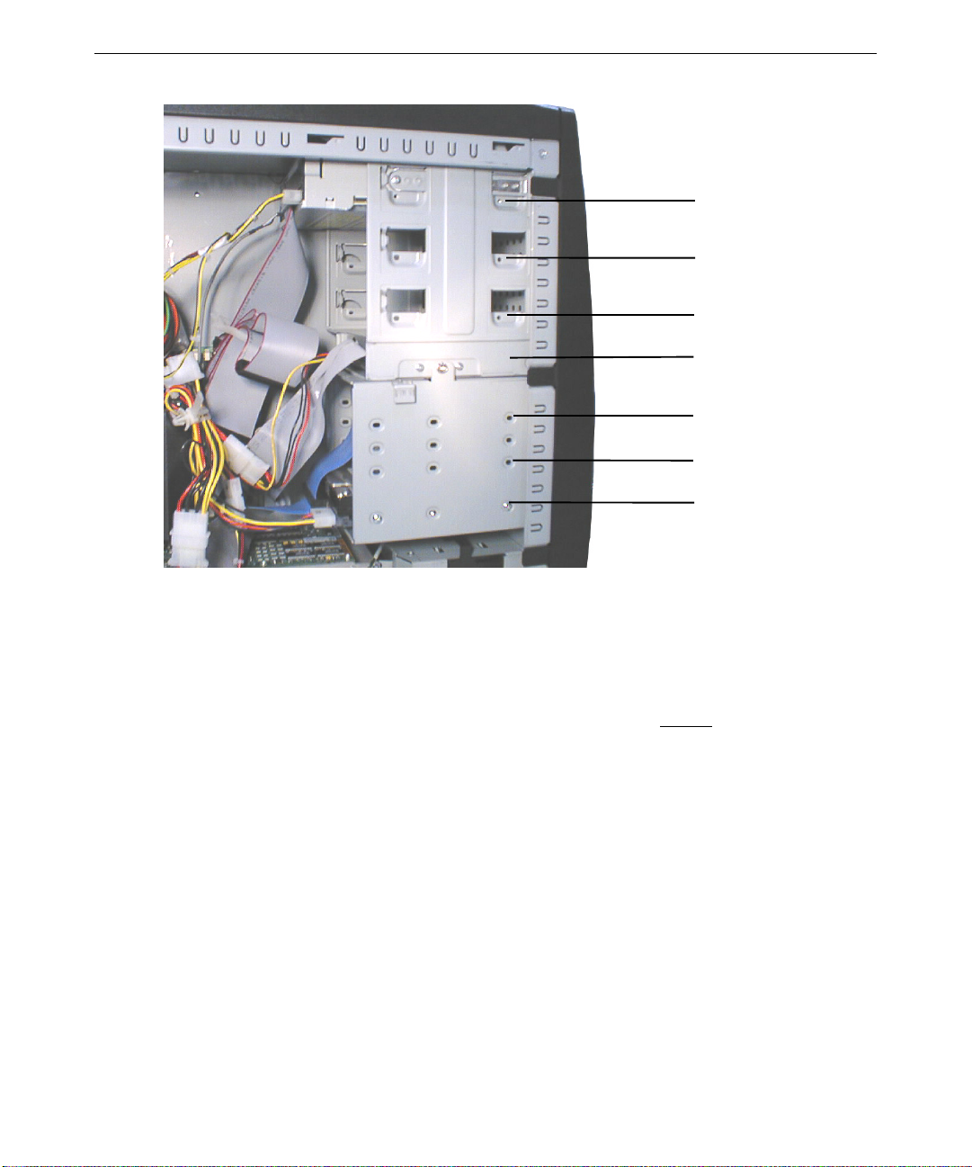
62
Bay 1
Bay 2
Bay 3
Bay 4
Bay 5
Bay 6
Bay 7
See Chapter 10, “Servicing System Components,” for instructions to replace or add an internal
peripheral device. See the System Board Manual for details on EIDE and SCSI device power and
data connections to the system board.
Remember the following when installing internal-access SCSI peripheral devices:
♦ The maximum speed of a SCSI bus is limited to the speed of the slowest device on that bus.
♦ Have the vendor’s documentation available to follow instructions for setting the SCSI ID,
enabling or disabling termination, installing device drivers when required, and configuring
other drive attributes.
♦ If you are installing a internal peripheral device that connects to an expansion card, see the
vendor’s documentation for installing the expansion card and required cables. See “Adding
Expansion Cards” for details.
Adding External SCSI Peripheral Devices
The system has a Symbios single-channel low-voltage differentia l signaling (LVDS) Wide Ultra2
SCSI controller card. You can connect Fast, Ultra, or Ultra2 SCSI devices to the card’s external
port. See Chapter 1, “Setting Up the Hardware,” to locate the SCSI port.
Page 75

SCSI Cable Lengths and Device Speeds
For each SCSI bus, the type of bus and the data clock speed of the fastest device on that bus
determine its maximum length. Knowing this, you can determine the maximum cable length you
can use to connect external SCSI devices to the system.
The following table provides a guide to maximum SCSI bus length. Note that bus width (for
example, Narrow versus Wide) does not affect the maximum bus length.
63
Fastest device on the bus
5 MHz (SCSI-1) 19.7 ft / 6 m 82 ft / 25 m 39.4 ft / 12 m
10 MHz (SCSI-2 or Fast) 9.8 ft / 3 m 82 ft / 25 m 39.4 ft / 12 m
20 MHz (Ultra or Fast20) 4.9 ft / 1.5 m 39.4 ft / 12 m 39.4 ft / 12 m
40 MHz (Ultra2 or Fast40) * Not recommended Not specified 39.4 ft / 12 m
* Bus used in the system
The total cable length on the system’s Wide Ultra2 SCSI bus is the sum of the following:
♦ Internal SCSI cable—40 inches (1.0 meter).
♦ SCSI cable between the system and the first external device
♦ SCSI cables between additional external devices
♦ SCSI cable inside each device connected to the cable−typically 8 inches (0.2 meters) or less
The maximum speed of a SCSI bus is limited to the speed of the slowest device on that bus.
SCSI Cable Quality
To ensure data integrity and optimum performance, do the following:
♦ Use the shortest cables possible to connect SCSI devices to the system and to each other.
Single-ended bus Differential bus LVDS bus
♦ Use high-quality SCSI cables to ensure adequate shielding (impedance of 110 to 135 ohms).
CAUTION When handling cables, flex them as little as possible. Ensure that cables do not
contact sharp metal surfaces or become excessively bent or twisted. In particular,
SCSI cables should not have any creased bends.
Page 76

64
SCSI IDs
By default, specific devices use the following SCSI IDs:
♦ System disk drive (standard) uses ID 0
♦ SCSI controller uses ID 7
NOTE To easily determine the ID of each SCSI device on the system, restart the system.
When the BIOS screen displays, look for the list of SCSI devices and write down the
ID for each device.
Some SCSI devices feature push switches to set the ID, while others have DIP switches or
jumpers. See the vendor documentation for details on setting the ID.
Connecting External SCSI Devices
To connect external SCSI devices:
1. If the system is connected to AC power and operating, shut down the system and unplug the
system power cord from its AC power outlet.
2. Connect one end of a SCSI cable to the SCSI port on the system.
3. Connect the other end of the SCSI cable to a SCSI peripheral device.
4. Connect a SCSI cable between SCSI ports on any additional SCSI peripheral devices.
5. Set the SCSI ID of each peripheral device to a unique
ID numbers already used by the system.
6. For each SCSI peripheral device connected to the port, if the device is:
− The last or only device on the SCSI chain, enable SCSI termination
− Not the last or only device on the SCSI chain, disable or remove SCSI termination
7. Ensure that the power switch on each peripheral device is in the off position; then connect the
power cord from each peripheral device to an AC power outlet.
8. Turn on power to all connected SCSI peripheral devices, and then start the system.
9. If necessary, install software drivers and configure the peripheral devices according to the
vendor’s instructions.
Most SCSI controllers do not recognize a hard disk drive formatted using a different brand of
controller. You must use Symbios-formatted hard disk drives with a Symbios SCSI controller.
If you want to boot the system from an external SCSI hard disk drive, ensure the SCSI controller to
which the boot drive is connected is installed lower in slot order than all other bootable SCSI
controllers and devices.
SCSI ID number. Do not use any SCSI
Page 77

Changing SCSI Controller or Device Settings
You may need to use the SCSI Configuration Utility (PCI_CFG.EXE) to configure the operation of
SCSI peripherals connected to the integrated Symbios SCSI controllers. This utility enables you to
configure SCSI controllers, perform a low-level format on a SCSI hard disk drive, select boot
order, and verify media.
You may need to change SCSI controller parameters on a per-device basis under the following
conditions:
♦ If you are advised to do so by Intergraph Computer Systems technical support or instructed to
do so by the vendor documentation supplied with the SCSI device.
♦ If the SCSI device does not negotiate properly with the controller.
♦ If you exceed the recommended total cable length for connecting SCSI devices to the system.
♦ If you connect non-Ultra or non-Ultra2 SCSI external devices to the system.
For more information on the SCSI Configuration Utility, see Chapter 3, “Configuring the System.”
Upgrading Processors
65
You can upgrade a single-processor system by adding another processor. When higher-speed
processors become available, you can upgrade one- or two-processor systems by replacing the
existing processors with faster processors.
Processors are mounted in a retention module that surrounds the processor slots. See Chapter 10,
“Servicing System Components,” and the System Board Manual for information on replacing a
processor or adding a new processor.
Follow these rules when adding or replacing processors:
♦ When adding a processor to a single-processor system, the new processor must be the same
speed as the existing processor.
♦ When replacing dual processors with faster processors, both processors must be the same
speed.
♦ After installing faster processors, you must reinstall Windows NT on the system to ensure
proper operation with the new processors.
Page 78

66
Page 79

10 Servicing the System
This chapter describes how to replace the major components of your Zx1 workstation.
WARNING This is a user-serviceable system. Service and upgrade tasks should be
performed by users who can follow instructions in a manual to service
equipment, and can do so without harm to themselves or damage to the
equipment.
Before You Begin
WARNING The system is always on when connected to AC power. Before opening the
system, disconnect the system’s power cord from its AC power outlet.
WARNING Internal components may be at high temperatures. Allow time for them to cool
before handling them.
WARNING Internal components can be damaged by static electricity. Use an antistatic
wrist strap connected to the bare metal of the system’s chassis to protect
against electrostatic discharge.
67
NOTE “Right side” and “left side” are as seen from the front of the system.
See Chapter 8, “Gaining Access to System Components,” for details on opening the system and
protecting against electrostatic discharge.
The procedures in this chapter assume you have already removed the left side panel from the
system.
Page 80

68
Floppy Disk Drive
The floppy disk drive occupies the lowest front-access device bay.
Floppy Disk Drive
Power and Data
Cables
Device Screws
(both sides)
To replace the floppy disk drive:
WARNING The system is always on when connected to AC power. Before performing this
task, disconnect the system’s power cord from its AC power outlet.
1. Disconnect the power and data cables from the drive.
1. Remove and retain the screws securing the floppy disk drive to its bay.
2. Slide the drive out the front of the base unit chassis.
3. Connect the data and power cables to the new floppy disk drive.
4. Slide the new drive into the base unit chassis.
5. Secure the new drive to its bay with the screws removed previously.
6. Replace the faceplate.
Page 81

Front-Access Peripheral Device
Three 5.25-inch x 1.6-inch peripheral devices may be installed in front-access device bays.
Peripheral devices in these bays are accessible from the front of the system. The CD-ROM drive
occupies the topmost front-access device bay. Other front-access devices can include Zip or Jaz
drives, tape drives, and CD-Recorder (CD-R) drives.
69
CD-ROM Drive
Power and Data
Cables
Bays for Other
Front-Access
Devices
To add or replace a front-access peripheral device:
WARNING The system is always on when connected to AC power. Before performing this
task, disconnect the system’s power cord from its AC power outlet.
WARNING The CD-ROM drive contains a laser and is classified as a Class 1 Laser
Product. To prevent direct exposure to the laser beam and to avoid hazardous
radiation exposure, do not try to open the CD-ROM drive enclosure. Return the
drive to the manufacturer for repair.
1. Remove the faceplate. See Chapter 8, “Gaining Access to System Components.”
2. If adding a front-access device, remove the plastic blank from the faceplate and the metal
blank from the base unit chassis that cover the opening for the device.
3. If replacing a front-access device, disconnect the power and data cables from the device.
Page 82

70
(both sides; push in)
4. If replacing a front access device, push in the release tab on each side of the device and pull
5. Remove the drive rails from the old device and secure them to the new device.
Drive Rail
(both sides)
Release Tab
the drive out the front of the chassis.
6. Slide the new device into the base unit chassis until the release tabs engage.
7. Connect the data and power cables to the new device.
8. Replace the faceplate.
Internal-Access Peripheral Device
WARNING Mishandling a removed disk drive can cause the heads to crash! Subsequent
failures may not be noticeable for three to six months. Handle disk drives
carefully to avoid damage.
Three 3.5-inch x 1.0-inch peripheral devices, or two 3.5-inch x 1.6-inch peripheral devices, may be
installed in the internal-access device bays. These bays are located in a removable cage beneath
the front-access device bays, immediately under the floppy disk drive. Peripheral devices in these
bays are not accessible from the front of the system. Such devices are usually disk drives,
including the system’s primary disk drive.
Page 83
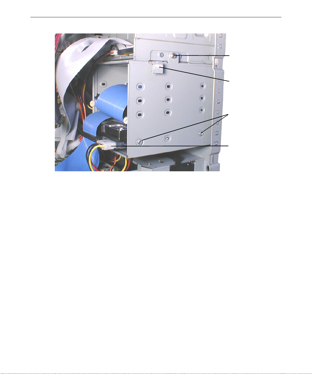
Device Cage Screw
Release Lever
(push in)
Device Screws
(both sides)
Power and Data
Cables
71
To add or replace an internal-access peripheral device:
WARNING The system is always on when connected to AC power. Before performing this
task, disconnect the system’s power cord from its AC power outlet.
1. Disconnect the power and data cables from all of the devices in the internal-access device
cage. Note which cables connect to each device.
2. Remove and retain the screw securing the cage to the base unit chassis.
3. Push the release lever and slide the cage back, down, and out of the base unit chassis.
4. If replacing an internal-access device, remove and retain the screws securing the device to the
cage, and remove it from the cage.
5. Place the new device in the cage and secure it with the screws removed previously.
6. Align the tabs on the top of the internal-access device cage with the openings in the bottom of
the front-access device cage. Then push the release lever, and slide the cage up and forward
into the base unit chassis until the release lever engages.
7. Secure the cage to the base unit chassis with the screw removed previously.
8. Connect the power and data cables to all of the devices in the cage.
Page 84

72
Expansion Card
The system board contains sockets in which expansion cards (such as the graphics controller card)
are installed. See Chapter 9, “Upgrading the System,” and the System Board Manual for more
information on expansion cards and their sockets.
To avoid damaging an expansion card and voiding its warranty, take the following precautions:
♦ Handle the expansion card only by the edges. Do not touch the metallic finger contacts.
♦ Do not bend, twist, drop, or otherwise handle the expansion card carelessly.
♦ Do not expose the expansion card to moisture or extreme temperatures.
♦ Do not remove the expansion card from its antistatic package until you are ready to install it.
Retaining
Screw
Card Socket
Card Guides
Card Guides
To replace an expansion card:
WARNING The system is always on when connected to AC power. Before performing this
task, disconnect the system’s power cord from its AC power outlet.
1. Disconnect any external and internal cables from the expansion card.
2. Remove and retain the retaining screw that secures the card to the left card guide.
3. Pull the card straight out of its slot. Place the card on an antistatic surface.
Page 85

4. Remove the new card from its antistatic package and slide it into the slot from which you
removed the old card. Push the card into the slot until it seats firmly in the socket.
5. Secure the new card to the left card guide with the retaining screw (6-32 x 0.25 hex head)
removed previously.
6. Connect any internal and external cables to the new card.
Memory Module
The upper right area of the system board contains sockets for four dual inline memory modules
(DIMMs). See Chapter 9, “Upgrading the System,” and the System Board Manual for more
information on memory modules and their sockets. See Chapter 11, “System Hardware and
Specifications,” for detailed memory specifications.
CAUTION System memory modules from Intergraph Computer Systems are certified for use
with Intergraph computers at extremes of temperatures and system load to ensure
reliable performance. System memory modules available from other vendors may
not function properly or reliably in your Intergraph computer.
To avoid damaging a DIMM and voiding its warranty, take the following precautions:
73
♦ Do not touch the metallic finger contacts.
♦ Do not bend, twist, drop, or otherwise handle the DIMM carelessly.
♦ Do not expose the DIMM to moisture or extreme temperatures.
♦ Do not remove the DIMM from its antistatic package until you are ready to install it.
DIMM
Release Tab
Notch DIMM socket
To add or replace a DIMM:
WARNING The system is always on when connected to AC power. Before performing this
task, disconnect the system’s power cord from its AC power outlet.
1. If replacing a DIMM, press the DIMM socket release tabs outward, away from each other;
then grasp the top edge of the DIMM and pull it out of the socket.
Page 86

74
2. Remove the new DIMM from its antistatic package. Verify the DIMM has gold-plated fingers
that match the gold-plated socket contacts, and the slot keys on the DIMM match the slot keys
in the DIMM socket.
3. Orient the DIMM so that the notches match the keys in the socket.
4. Push gently straight down until the release tabs snap into place.
5. Restart the system for the BIOS to detect the new memory.
Processor Module
The upper left area of the system board contains sockets for two Slot 1 processors. See Chapter 9,
“Upgrading the System,” and the System Board Manual for more information on processor
modules and their sockets.
Processor
Retention module
Heat sink mounting bracket
Heat sink lock
To replace a processor module:
WARNING The system is always on when connected to AC power. Before performing this
task, disconnect the system’s power cord from its AC power outlet.
1. For ease of access, you may have to remove the rear fan and cooling duct. See “Cooling
Fans” in this chapter.
2. Remove the heat-sink lock from within the heat-sink fins, if necessary, by pressing the ends of
the lock inward and pulling lock outward.
3. Press the locking tabs on the top corners of the processor inward, towards each other, until
they click into the release position.
Page 87

4. Slide the processor module out of the retention module.
5. Remove the new processor from its antistatic package and align the processor module over the
retention module. The processor module is keyed and fits only one way.
6. Press the processor module down until it seats.
7. Press the processor module locking tabs outward until they click into the locked position.
8. Install the heat-sink lock between the heat-sink fins, if necessary, by sliding the lock between
the fins and pressing it onto the heat-sink lock mounting posts.
Power Supply
WARNING There are no user-serviceable parts in the power supply. Return the power
supply to the manufacturer for repair.
The power supply is located in the upper section of, and is secured to the back of, the base unit
chassis. See Chapter 11, “System Hardware and Specifications,” for technical information on the
power supply.
75
Power Supply
Power Cables
Power Supply Shelf
To replace the power supply:
WARNING The system is always on when connected to AC power. Before performing this
task, disconnect the system’s power cord from its AC power outlet.
1. Disconnect the AC power cord from the AC power receptacle at the back of the base unit
chassis.
Page 88

76
2. Disconnect all power cables from all internal peripheral devices and the system board. Note
the locations to which the power cables are connected:
Cable
Connects to
P1 and P2 ATX power connectors on the system board
P3 through P 8 CD-ROM drive, disk drives, and other peripheral devices
P9 Floppy disk drive
AC Power Receptacle
AC Voltage Selection Switch
3. Remove and retain the screws securing the power supply to the back of the base unit chassis.
CAUTION Support the power supply as you remove the screws. Do not let the power supply fall
or damage to equipment may result.
4. Remove the power supply from its shelf and the base unit chassis.
5. Place the new power supply on its shelf in the base unit chassis and secure it with the four
screws removed previously
6. Make sure the AC voltage selection switch on the power supply (on the back of the base unit)
is set to the proper line voltage for your location.
− If your location uses 90 to 135 volts, the number 115 must be visible.
− If your location uses 180 to 264 volts, the number 230 must be visible.
WARNING If you do not set the AC voltage selection switch on the power supply correctly,
equipment damage may occur when you turn on power to the system.
7. Reconnect the power cables to the system board and internal devices.
8. Reconnect the AC power cable to the AC power receptacle at the back of the base unit chassis.
Page 89

Cooling Fans
Two internal fans ensure proper airflow to cool system components in the base unit. One fan is
installed in a housing at the front of the base unit chassis. Another fan is secured to the rear of the
base unit chassis, and has a cooling duct to direct the airflow over the system’s processors.
CAUTION Arrows on each fan indicate airflow direction and rotation. Install each fan with the
airflow arrow pointing into the chassis to ensure proper cooling of system
components.
77
Fan Release
Fan Assembly
Fan Cable Connector
To replace the front fan:
WARNING The system is always on when connected to AC power. Before performing this
task, disconnect the system’s power cord from its AC power outlet.
1. Disconnect the fan’s power cable from its power supply connector.
2. Disengage the release on top of the fan assembly in the expansion card guide, and gently pull
the fan assembly out of its housing.
3. Feed the power cable for the ne w fan int o the front fan housi ng and through the lowest
opening in the card guide assembly.
4. Align the new fan assembly with the opening in its housing, and gently push the fa n assembly
into its housing until the release on top of the fan assembly engages.
5. Connect the new fan’s power cable to its power supply connector.
Page 90

78
Rear Fan Screws
To replace the rear fan:
WARNING The system is always on when connected to AC power. Before performing this
task, disconnect the system’s power cord from its AC power outlet.
1. Remove the cooling duct to gain access to the rear fan. Depending on your system’s
configuration, you will have to either unsnap the duct from the rear fan housing, or pop the
duct out of its catches on the rear fan housing.
2. Disconnect the fan’s power cable from its power supply connector.
3. Remove and retain the screws securing the fan to the back of the base unit chassis.
CAUTION Support the fan as you remove the screws. Do not let the fan fall onto any installed
expansion cards.
4. Note the airflow direction of the new fan (into the chassis) and the position the fan correctly
on the chassis.
5. Replace the screws removed previously to secure the fan to the chassis.
6. Connect the fan’s power cable to its power supply connector.
7. Replace the cooling duct. Depending on your system’s configuration, you will have to either
snap the duct to the rear fan housing, or pop the duct into its catches on the rear fan housing.
Page 91

System Board
If you need to replace your workstation’s system board, you must swap the DIMMs and the
processor modules from the old system board to the new one. See the System Board Manual for
connector and socket locations.
To remove the system board:
WARNING The system is always on when connected to AC power. Before performing this
task, disconnect the system’s power cord from its AC power outlet.
1. Lay the chassis down on its right side.
2. Note the locations where all cables are connected to the system board, and then disconnect all
cables from the system board.
3. Note the locations of the expansion cards, remove them, and place the cards on an antistatic
surface. See the previous procedures in this chapter for more information.
4. Remove the DIMMs and the processor modules and place them on an antistatic surface. See
the previous procedures in this chapter for more information.
5. Remove the jackscrews on all external port connectors.
6. Remove the screws and the plastic rivets on the processor retention modules, and remove the
retention modules from the chassis.
79
7. Remove the 13 screws from the system board.
8. Lift the system board out of the chassis and place it on an antistatic surface.
To install a new system board:
WARNING The system is always on when connected to AC power. Before performing this
task, disconnect the system’s power cord from its AC power outlet.
1. Place the new system board into the chassis and align all mounting holes.
2. Install the jackscrews on all external port connectors.
3. Loosely install the remaining screws on the system board, except those for the processor
retention modules. Do not tighten the screws yet.
4. Mount the retention modules to the system board with the plastic rivets. The retention
modules are keyed to the processor slots to ensure correct orientation.
5. Tighten all fasteners that secure the system board and retention modules to the chassis.
6. Install the DIMMs and the processor modules to the system board.
7. Install the expansion cards back into their original slots.
8. Connect the internal cables to the system board. If you need help identifying cable
connections, see the System Board Manual.
Page 92

80
CMOS/Clock Lithium Battery
The CMOS/clock lithium battery is located toward the bottom right side of the system board. The
battery may be hidden under installed expansion cards.
Battery
When you remove the battery, the system will lose its operating parameters stored in CMOS
memory. As a result, the system BIOS parameter settings are lost. After you install a new battery,
you must reset the date and time and reconfigure the BIOS. See Chapter 7, “Configuring the
BIOS,” for details on using BIOS Setup to configure the BIOS.
To replace the battery:
WARNING The system is always on when connected to AC power. Before performing this
task, disconnect the system’s power cord from its AC power outlet.
1. Remove any expansion cards that restrict access to the battery.
2. Note the positive orientation of the battery. Carefully remove the discharged battery by
grasping it firmly and pulling it out of the socket.
3. Install the new battery in the same orientation as the old battery.
WARNING There is a danger of explosion if the battery is incorrectly replaced. Replace
the battery with the same or equivalent type only, as recommended by the
battery manufacturer. Dispose of used batteries according to the battery
manufacturer's instructions.
4. Install the expansion cards that you removed.
5. Dispose of the battery according to the manufacturer’s instructions.
Page 93

Power Switch, System LEDs, and Light Pipe
The power switch and system LEDs are mounted to the front of the base unit chassis. A light pipe
secured to the faceplate guides the light from the LEDs to openings on the faceplate. See the
System Board Manual for power switch and LED connector locations and details.
Power Switch
Power LED
Disk LED
81
To replace the power switch:
WARNING The system is always on when connected to AC power. Before performing this
task, disconnect the system’s power cord from its AC power outlet.
1. Remove the faceplate. See Chapter 8, “Gaining Access to System Components.”
2. Remove the internal-access device cage. See “Internal-Access Peripheral Device” in this
chapter.
3. Disconnect the power switch cable from its connector on the system board.
4. Remove and retain the screw that secures the power switch to the base unit chassis.
5. Turn the power switch until its key matches the keyhole in the chassis, and then pull the power
switch into the chassis.
6. Remove the power switch from the chassis.
7. From inside the chassis, turn the new power switch until its key matches the keyhole in the
chassis, and then push the new power switch into the hole.
8. Turn the power switch until the screw hole in the switch matches the screw hole in the chassis,
and then secure the switch to the chassis with the screw removed previously.
9. Connect the power switch cable to its connector on the system board.
10. Replace the internal-access device cage.
11. Replace the faceplate.
Page 94

82
To replace an LED:
WARNING The system is always on when connected to AC power. Before performing this
task, disconnect the system’s power cord from its AC power outlet.
12. Remove the faceplate. See Chapter 8, “Gaining Access to System Components.”
13. Remove the internal-access device cage. See “Internal-Access Peripheral Device” in this
chapter.
14. Disconnect the LED cable from its connector. The power LED is connected to the system
board. The disk drive LED is connected to the SCSI controller card.
15. Gently spread the tabs holding the LED to the chassis, and pull the LED into the chassis.
16. From inside the chassis, gently push the new LED into the tabs that hold it to the chassis until
it clicks into place.
17. Connect the LED cable to its connector (on the system board or on the SCSI controller card,
as appropriate).
18. Replace the internal-access device cage.
19. Replace the faceplate.
Light Pipe
Light Pipe Screw
To replace the light pipe:
WARNING The system is always on when connected to AC power. Before performing this
task, disconnect the system’s power cord from its AC power outlet.
1. Remove the faceplate. See Chapter 8, “Gaining Access to System Components.”
2. Remove and retain the screw securing the light pipe to its mount on the back of the faceplate.
3. Remove the light pipe.
4. Secure the new light pipe to the mount on the back of the faceplate with the screw removed
previously.
5. Replace the faceplate.
Page 95

11 System Hardware and Specifications
This chapter contains information about hardware, resources, and specifications for your Zx1
workstation.
This chapter does not contain detailed information on the workstation’s system board. See the
System Board Manual delivered with your workstation for detailed information on the system
board and its components, memory, slots and sockets, jumpers and connectors, and external ports.
Functional Diagram
The following diagram shows the power and data signals of the base unit components.
83
Power
Data
Power and Data
System Board
AC In
Audio
Keyboard
Mouse
Monitor
Serial
Ports
Parallel
Port
EIDE
SCSI
AC In
Power Supply
Fans
Floppy Disk Drive
CD-ROM Drive
Disk Drives
(Internal/External)
USB
Page 96

84
Floppy disk drive
Internal Peripheral Cabling
The following sections show EIDE and SCSI cable routings and connections to internal peripheral
devices, and depicts standard and optional cables used in the system. For detailed information and
the location of EIDE and SCSI connectors on the system board, see the System Board Manual.
CAUTION When handling cables, flex them as little as possible. Ensure that cables do not
contact sharp metal surfaces or become excessively bent or twisted. In particular,
SCSI cables should not have any creased bends.
EIDE Cabling
The installed EIDE cable connects the primary EIDE channel to the CD-ROM drive and to another
front-access peripheral device. Another EIDE cable, which can connect the secondary EIDE
channel to two front-access peripheral devices, is provided with the system but is not installed.
CD-ROM drive
Installed cable connects primary
EIDE channel to CD-ROM drive and
to one front-access device
Additional cable (provided but not
installed) connects secondary EIDE
channel to two front-access devices
Page 97

SCSI Cabling
y
An installed SCSI cable connects the single-channel LVDS SCSI controller card to up to three
internal SCSI disk drives. External SCSI devices can connect to the controller’s external SCSI
port on the back of the base unit.
CD-ROM drive
Cable connects SCSI controller card
to three disk drives in internal-access
device ba
s
85
External SCSI devices connect to
SCSI controller card’s external port
An additional SCSI controller card is required to control any SCSI peripheral devices installed in
front-access device bays.
Page 98

86
Floppy Disk Drive Cable
1
2
Connector Connects To
1 Floppy disk drive controller on system board
2 Floppy disk drive
EIDE Device Cables (Installed and Optional)
1 32
Connector Connects To
1 EIDE connector on system board
2EIDE device
3 EIDE CD-ROM drive (installed cable) or EIDE device (optional cable)
Internal-Access Device SCSI Cable
1 32
4
Connector Connects To
1 SCSI internal connector on SCSI controller card
2 SCSI device in internal-access device cage
3 SCSI device in internal-access device cage
4 SCSI device in internal-access device cage
Page 99

Power Supply
The 300 Watt power supply has a manual switch for selecting either 115 VAC (90-132 VAC)
range or 230 VAC (180-264 VAC) range for domestic or international locations. The input
frequency is 47-63 Hz, single phase. Input current is 7 amps maximum for the 115 VAC range and
3.5 amps for the 230 VAC range. The power supply has a typical efficiency of 70 percent at
maximum output load. The power supply is enclosed in a case that includes a fan for additional
airflow.
The 300-Watt power supply has the following DC output specifications:
Outputs →
Nominal Output Voltages (VDC) +5.02+3.32+12.0 -12.0 -5.0 +5.0
Maximum Current Rating (ADC) 30 22 10 0.8 0.5 1
1. Standby +5.0 VDC output voltage is always on.
2. Maximum +5.0 V and +3.3 V combined power is 180W.
The power supply has two power cables, P1 and P2, that connect to ATX power connectors on the
system board.
1 2 3 4 5 6
87
1
The power supply has six periphera l device power cables (P3 through P8) and o ne floppy disk
drive power cable (P9). Depending on your system configuration, these cables connect in daisy
chains to the power supply and to each other as follows:
Configuration 1
Power Supply → P3 → P4 Power supply → P3 → P4 → P5
Power Supply → P5 → P6 Power supply → P6 → P7 → P8 → P9
Power Supply → P7 → P8 → P9
See Chapter 10, “Servicing System Components,” for details on replacing the power supply.
P1 Connector Pinout
Pin
1 +3.3V 6 +5.0 V 11 +3.3 V * 16 Ground
2 +3.3V 7 Ground 12 -12.0 V 17 Ground
3 Ground 8 Power Good 13 Ground 18 -5.0 V
4 +5.0V 9 5.0 V Standby 14 Remote On 19 +5.0 V
5 Ground 10 +12.0 V 15 Ground 20 +5.0 V
* + Sen se
Signal Pin Signal Pin Signal Pin Signal
Configuration 2
Page 100

88
P2 Connector Pinout
Pin
1 +3.3V 6 NC 11 +3.3 V 16 NC
2 +3.3V 7 Ground 12 NC 17 Ground
3Ground 8NC 13NC 18NC
4 NC 9 NC 14 NC 19 NC
5 NC 10 +12.0 V 15 NC 20 +5.0 V
P3 through P8 Connector Pinout
Pin
1 +5.0 V 3 Ground
2 Ground 4 +12.0 V
P9 Connector Pinout
Pin
1 +12.0 V 3 Ground
2Ground 4+5.0 V
Signal Pin Signal Pin Signal Pin Signal
Signal Pin Signal
Signal Pin Signal
Cooling Fans
The system has two thermally controlled 92 mm 12 V DC cooling fans. One fan is mounted in a
housing at the bottom front of the base unit chassis. Another fan is mounted to the upper back of
the base unit chassis under the system’s power supply. Both fans pressurize the chassis and force
warm air out of the base unit’s vents.
The chassis fans are field replaceable. See Chapter 10, “Servicing System Components,” for
details on replacing the chassis fans.
CAUTION Arrows on each fan indicate airflow direction and rotation. Ensure each fan has the
airflow arrow pointing into the chassis to ensure proper cooling.
The power supply contains its own cooling fan, which is not field replaceable. If the power supply
fan requires replacement, you must replace the power supply. See Chapter 10, “Servicing System
Components,” for details on replacing the power supply.
 Loading...