

Fibre Channel User’s Guide
Congratulations on purchasing Intergraph’s state-of-the-art Fibre Channel storage solution. If
you are a manager, you will find this solution gives you matchless performance in a costcompetitive storage device. If you are a technician, you will find this solution easy to install,
reliable, and easy to maintain. If you are a user, you will enjoy fast access to a vast expanse of
storage space.
Using This Document
The Fibre Channel User’s Guide contains all the information you need to install and use your
Fibre Channel disk array. This document is organized as follows:
u
SS-1200 FCAL Rack Installation and User Guide describes how to install, configure, and
connect the Fibre Channel enclosure to your system, and how to use and maintain it.
u
SS-1200 FCAL LRC Input/Output Module Installation Guide describes how to install the
Fibre Channel Arbitrated Loop (FCAL) Loop Resiliency Circuit (LRC) input/output (I/O)
modules in the Fibre Channel enclosure.
u
SS-1200 FCAL Drive Carrier Module Installation Guide describes how to install the FCAL
drive carrier modules in the Fibre Channel enclosure.
Before You Begin
CAUTION To protect the Fibre Channel enclosure and related equipment from electrostatic
discharge, wear an anti-static wrist strap when setting up or reconfiguring the
enclosure.
WARNING To avoid damage to the enclosure’s power supply, set the voltage range
switch on the power supply to the proper AC line voltage for your location
(115 V or 220 V) before you connect the power cord and turn on power to
the enclosure.
Customer Support
Intergraph Computer Systems offers an assortment of customer support options.
u
Intergraph Computer Systems provides a variety of hardware services for Intergraph and
third-party equipment. Services include warranty upgrades, repair depot service, on-site
hardware maintenance, system administration, and network consulting. Hardware purchased
from Intergraph Computer Systems includes a factory warranty ranging from 30 days to three
years. A detailed warranty description is available on the World Wide Web; see the Support
pages at http://www.intergraph.com/ics.
u
Intergraph Computer Systems provides complimentary software support for 30 or 90 days
following shipment of a hardware or software product. This includes World Wide Web
access, Intergraph Bulletin Board Service access, FAXLink service, and telephone (Help
Desk) support. At the end of the complimentary support period, you can purchase other
levels of software support.
DHAV04500

2
u
You can visit Intergraph Computer Systems on the World Wide Web at
http://www.intergraph.com/ics. On these pages, you can get news and product
information, technical support information, software updates and fixes, and more.
u
On the Intergraph Bulletin Board Service (IBBS), you can get technical support information,
software updates and fixes, and more. Using a modem (eight data bits, no parity, one stop
bit, any baud rate up to 14,400), call 1-256-730-8786. If you have trouble connecting to or
using the IBBS, call the Customer Response Center (see below).
u
To get information on technical support via the FAXLink, call 1-800-240-4300. To get
documents via the FAXLink (up to five per call), call 1-256-730-9000.
u
To get customer support by telephone:
− In the United States, call the Customer Response Center at 1-800-633-7248 between the
hours of 7:00 a.m. and 7:00 p.m. Central Time, Monday through Friday (except
holidays).
− Outside the United States, contact your local Intergraph Computer Systems subsidiary or
distributor.
Have the following information available when you call:
− Your service number, which identifies your site to Intergraph Computer Systems. You
use your service number for warranty or maintenance calls.
− Your Customer Personal Identification Number (CPIN). You get a CPIN the first time
you call the Customer Response Center; it is associated with your service number for
future call logging.
− The product’s name or model number.
− The product’s serial number. Software product serial numbers are included in the
product packaging. Hardware product serial numbers are on a sticker affixed to the
hardware product.
− Your name and telephone number.
− A brief description of the question or problem.
u
To get information on more customer support options:
− Visit the Support pages on the World Wide Web at http://www.intergraph.com/ics.
− For hardware support questions in the United States, call 1-800-763-0242.
− For software support questions in the United States, call 1-800-345-4856.
− Outside the United States, contact your local Intergraph Computer Systems subsidiary or
distributor.

SS-1200-FCAL Rack Installation and User Guide
Part No. 19933-01
Issue 1.0
June 01, 1998

SS-1200-FCAL User Guide
Notices
The information in this document is subject to change without notice.
While every effort has been made to ensure that all information in this document is accurate, the Authors accept no
liability for any errors that may arise.
No part of this document may be transmitted or copied in any form, or by any means, for any purpose, without the
written permission of the Authors.
Issue 1.0 June 01, 1998 Part No. 19933-01
ii

Preface
International St andards
The Xyratex SS-1200 series storage system complies with the requirements of the following agencies and standards:
• CE to IEC 950/EN60951
•UL
•cUL
Potential for Radio Frequency Interference
USA Federal Communications Commission (FCC)
Note This equipment has been tested and found to comply with the limits for a class A digital dev ice, pursuant to Part 15
of the FCC rules. These li mits are desi gned to p rovid e reason able p rotectio n aga inst ha rmful interfere nce when the
equipment is oper a ted in a commercial environment . This equipment generates, uses and can radiate radio
frequency energy and, if not installed and used in accordance with the instruction manual, may cause harmful
interference to radio communications. Operation of this equipment in a residential area is likely to cause harmful
interference in which case the user will be required to correct the interference at his own expense.
Properly shielded and grounded cables and connectors must be used in order to meet FCC emission limits. Xyratex
is not responsible f or any radio or television interference caused by using oth er than recommended cables and
connectors or by unauthorized changes or modifications to this equipment. Unauthorized changes or modifications
could void the user’s authorit y t o operate the equipment.
This device complies with Part 15 of the FCC Rule s. Oper atio n is subject to the following two conditions: (1) this
device may not cause harmful interference, and (2) this device must accept any in terference received, including
interference that may cause undesired operation.
European Regulations
This equipment complies with European Regulations EN 55022 Class A: Limits and Methods of Measurement of
Radio Disturbance Characteristics of Information Technology Equipments and EN50082-1: Generic Immunity.
Safety
Warning To ensure safe an d correct o peration o f the SS-12 00-FCAL s ubsy stem al l safety precauti ons and
instructions referred to in this user guide must be followed thoroughly.
Caution All plug-in modules and blank plates are part of the fire enclosure and must only be removed
when a replacement can be immediately added. The system must not be run without all units in
place.
Permanently unplug t he subsystem if you think that it has become damaged in any way and before you move it.
• An SS-1200-FCAL subsystem can weigh up to 45kg (99lb).Two people are required to remove or replace the
subsystem.
• The SS-1200-FCAL subsystem must only be operated from nominal power supply input voltages of 100 120V AC or 200 - 2 40V A C. Ensure that the corre ct rang e is se lecte d on each powe r supply prior to powe ring
on.
• The power supply cord is used as the main disconnect device. Ensure that the socket outlet is located near the
equipment and is easil y accessible.
iii

SS-1200-FCAL User Guide
• A trifurcated power cord, as supplied with the SS-1200-FCAL system, must be use d in order to safely provide
a single power disconnect point.
• If a power cord is not supplied with your SS-1200-FCAL system, a power cord suitable for t he country of
destination and for use with the SS-12 00 system application should be provided. Please refer to 1.4, ”SS-1200-
FCAL Technical Specification”, on page9 for details.
• If powered by multiple AC sources, disconnect all supply power for complete isolation.
• In order to comply with applicable safety, emission and thermal requirements no covers should be removed
and All bays must be fitted with either plug-in modules or blanking plates.
• The On/Off switches on each Power Supply/Cooling module On ly isolat e the power from that module. Any
other power supply/cooling modules will remain active.
• The power connection must always be disconnected pr ior to removal of the Power Supply/Cooling module
from the encl osure.
• Before operating the Power Supply/Cooling module, it must be secured by tightening the retaining screw on
the module front panel.
• The subsystem must not be run for extended periods without the ESI/Ops Panel Modul e being in place.
• A safe electrical earth connection must be provided to the power cord. Check the grounding of the enclosure
before applying power.
• Provide a suitable power source with electrical overload protection to meet the requirements laid down in the
technical specification.
Caution Rack System Precautions
Ensure that the rack system being used for your SS-1200-FCAL installation meets the following
parameters:
The rack design should incorporate stabilizing features suitable to prevent the rack from tipping forward
during inst allation.
The rack should comply with the airflow requirements detailed in the technical specification.
The rack should have a safe electrical distribution and grounding system.
Moving and Handling
Disk drives are very susc eptible to physical shock but damage may not be immediately obvious.
Please observe the f ollowing precautions before moving and handling the enclos ure:
• Always spin down devices prior to removing from the enclosure.
• If the SS-1200-FCAL enclosure has been installed in a 19 inch rack which is to be moved, remove all drives
and other plug-i n modules and repackage before transporting them separately.
• Keep all plug-in modules packaged to protect them until they are required for installation.
• Take care not to drop any of the pl ug-in modules or strike them onto a hard surface.
iv

Data Security
• Power down your host comp uter and all attached peripheral devices before beginning installation.
• Each enclosure contains up to 12 removable disk drive modules. Disk units are fragile. Handle them with care,
and keep them away from strong magnetic fields.
• All the supplied plug-in modules and blanking plates must be in place for the air to flow correctly around the
enclosure and also to complete the internal circuitry.
• If the subsystem is used with modules or blanking plates missing for more than a few minutes, the enclosure
can overheat, causing power failure and data loss. Such use may also invalidate the warranty.
• If you remove any drive module, you may lose data.
– If you remove a drive module, replace it immediately. If it is faulty, replace it with a drive module of the
same type and capacity
• Ensure that all disk drives are removed from the enclosure before attempting to manhandle or move the rack
installation.
Preface
• Do not abandon your ba c ku p r ou tin es . N o sy s te m is completely foolproof.
ESD Precautions
Warning It is recommended that you check an d fit a suitable anti-static wr ist or ankle strap and observe all
conventional ESD precautions when handling SS-1200-FCAL plug-in modules and components.
Avoid contact with backplane components and module connectors, etc.
Year 2000 Compliance
It is confirmed that all SS-1200 subsystem products have been designed and developed with Year 2000 compliance.
Special Tools and Equipment
There are no special tools requ ired but in o rder to c omplete the assembly of som e configu rations yo u may need th e
following (not supplied):
• Cross head and slotted screwdrivers.
• Security keys (one of these should be included wi th your SS-1200-FCAL enclosure for use with the drive
locks).
v

SS-1200-FCAL User Guide
Preface
What is in this guide
This user guide gives you step-by -step instructions on how to install, configure an d connect the Salient storage
subsystem to yo ur host computer system, and how to use and maintain the system.
Who should use this guide
This user guide assumes that you have a working knowledge of the Fi bre Channel Arbitrated Loop (FC-AL)
environment into which you are installing the SS-1200-FCAL system. If you do not have these skills, or are not
confident with the instructions in this guide, do not proceed with the installat ion.
Related publications
The SS-1200-FCAL Drive Carrier Module Installation Guide gives you step-by-ste p instru ctions on how to
install FC-AL drive carrier modules in a SS-1200-FCAL enclosure.
The SS-1200-FCAL LRC I/O Module Installation Guide gives you step-by-step instructions on how to install
the FC-AL I/O module in a SS-1200-FCAL enclosure.
The SS-1200 OEM Developer’s Guide provides sufficient information to enable third party system designers and
integrators to integrate a Salient system within a FC-AL environment.
vi

Contents
Contents
International Standards ................... .... ... ..................................... ... .... ............................................ ... ...................... iii
Potential for Radio Frequency Interference ............................................................................................................ iii
European Regulations ............................................................................................................................................. iii
Safety ...................................................................................................................................................................... iii
Moving and Handling ............................................................................................................................................. iv
Data Security ............................................................................................................................................................. v
ESD Precautions ....................................................................................................................................................... v
Year 2000 Compliance ............................................................................................................................................. v
Special Tools and Equipment ........................ ... .... .................................... .... .... ........................................................ v
Preface ............................................ .... ... ..................................... ... .... ..................................................................... vi
1 Introduction ......................................................... ...... ..... ................................................... ..... ......... 1
1.1 The SS-1200-FCAL System ......... .... ... ..................................... ... .... .................................... .... ....... .... ... ...... 1
1.2 The Enclosure Core Product .................................................................................................. ...................... 1
1.2.1 Enclosure Chassis .............................................................................................................................. 2
1.2.2 Tower Option ........ ... .... ... ..................................... ... .... .................................... .... .... ........................... 3
1.3 The Plug-in Modules ........................................................................ .... ... ............................................ ... .... .. 3
1.3.1 Power Supply/Cooling Module ................. .... .................................... ... .... .......................................... 3
1.3.2 Enclosure System Interface/Operators Panel Module ....................................................................... 4
1.3.3 Drive Carrier Modules ........................................................... .... ... ..................................................... 7
1.3.4 Loop Resiliency Circuit Input/Output Module (FC) .......................................................................... 7
1.3.5 Blank Plates ....................................................................................................................................... 8
1.3.6 Multiple Power Supply/Cooling Modules .......................................................................................... 8
1.3.7 Visible and Audible Alarms ................................................................................................................ 8
1.3.8 Anti-tamper Locks .............................................................................................................................. 9
1.4 SS-1200-FCAL Technical Specifi catio n ............. .... .................................... ... .... .......................................... 9
1.4.1 Dimensions ......................................... ... .... .................................... .... ... ..............................................9
1.4.2 Weight ........... .... .... .................................... .... ... .................................... .... .... ...................................... 9
1.4.3 Power ..... .... .................................... .... ... ..................................... ... .... ................................................. 9
1.4.4 Power Cord ............................................................. .... .... .................................... .... ......................... 10
1.4.5 Environment .................... .... .................................... .... .... .................................... .... ........... ... .... ....... 10
1.4.6 Interfaces ................................. ... ..................................... ... .... ............................................... ........... 11
1.4.7 Drive Carrier Module Specification ................................................................................................ 11
1.4.8 FC-AL LRC I/O Module Specification .............................................................................................11
2 Getting Started .............................................................................................................................. 13
2.1 Introduction ................................................................................................................................................ 13
2.2 Planning Your Installation ......................................................................................................................... 13
2.2.1 Enclosure Bay Numbering Convention ............................................................................................ 15
2.3 Installation .................................................................................................................................................. 15
2.3.1 Pre-Requisites .................................................................................................................................. 15
vii

SS-1200-FCAL User Guide
3 Operation ............................ ........................................................ ...... ..... ........................................ 25
2.3.2 Rack Mounting Rail Kit ......... ..................................... ... .... .................................... .... .... ........... ... .... 15
2.3.3 Chassis Installation ......................................................................................................................... 16
2.3.4 Power Supply/Cooling Module Installation .................................................................................... 17
2.3.5 ESI/Ops Panel Module Installation ......................................................... ... .... ................................. 19
2.3.6 Other Plug-in Modules ........................................... .... ... ..................................... ... .... ...................... 22
2.3.7 Interface Cabling ............................................................................................................................. 22
2.3.8 Blank Plates ................................... .................................... .... ... ............................................ .... ... .... 22
2.3.9 Power Cord Connection ........ .... .................................... .... .... .................................... .... ... ........ ... .... 23
2.3.10 Grounding Checks .......... .... ... ..................................... ... .... .................................... .... ...................... 23
3.1 Before You Begin ...................................................................................................................................... 25
3.2 Power On ................................................................................................................................................... 25
3.2.1 Standby Mode .................................................................................................................................. 25
3.2.2 Run Mode (Normal Operation) ....................................................................................................... 26
3.3 Operator Panel LEDs ................................................................................................................................. 26
3.4 Starting the Drives ..................................................................................................................................... 27
3.4.1 Disk Drives LEDs ............................................................................................................................ 28
3.5 Power Down .............................................................................................................................................. 28
4 Troubleshooting and Problem Solving ....................................................................................... 29
4.1 Overview ................................................................................................................................................... 29
4.2 LEDs .......................................................................................................................................................... 29
4.3 Audible Alarm ........................................................................................................................................... 30
4.3.1 Audible Alarm Mute ........................................................................................................................ 31
4.4 Test Mode .................................................................................................................................................. 31
4.5 Troubleshooting ......................................................................................................................................... 31
4.5.1 System Faults ................................................................................................................................... 31
4.5.2 Power Supply/Cooling Fault s ............................................................................ ... .... ...................... 32
4.5.3 Thermal Control .............................................................................................................................. 32
4.5.4 Thermal Alarm ................................................................................................................................ 33
4.5.5 Thermal Shutdown ........................................................................................................................... 33
4.6 FC-AL Drive Carrier Module Faults ......................................................................................................... 34
4.7 Dealing with Hardware Faults ................................................................................................................... 34
4.8 Continuous Operation During Replacement ....................................................................... .... ... ............... 34
4.9 Replacing a Module ................................. .................................... .... ... ....................................................... 34
4.9.1 Power Supply/Cooling Module .......................................................................... ... .... ...................... 35
4.9.2 ESI/Ops Panel Module ......................... .... ... ..................................... ... .... ........................................ 36
4.10 List of Spare Parts and Ancillary Items ..................................................................................................... 37
Glossary .................................................................................................................................................................. 39
Index ....................................................................................................................................................................... 41
viii
Chapter 1
Introduction
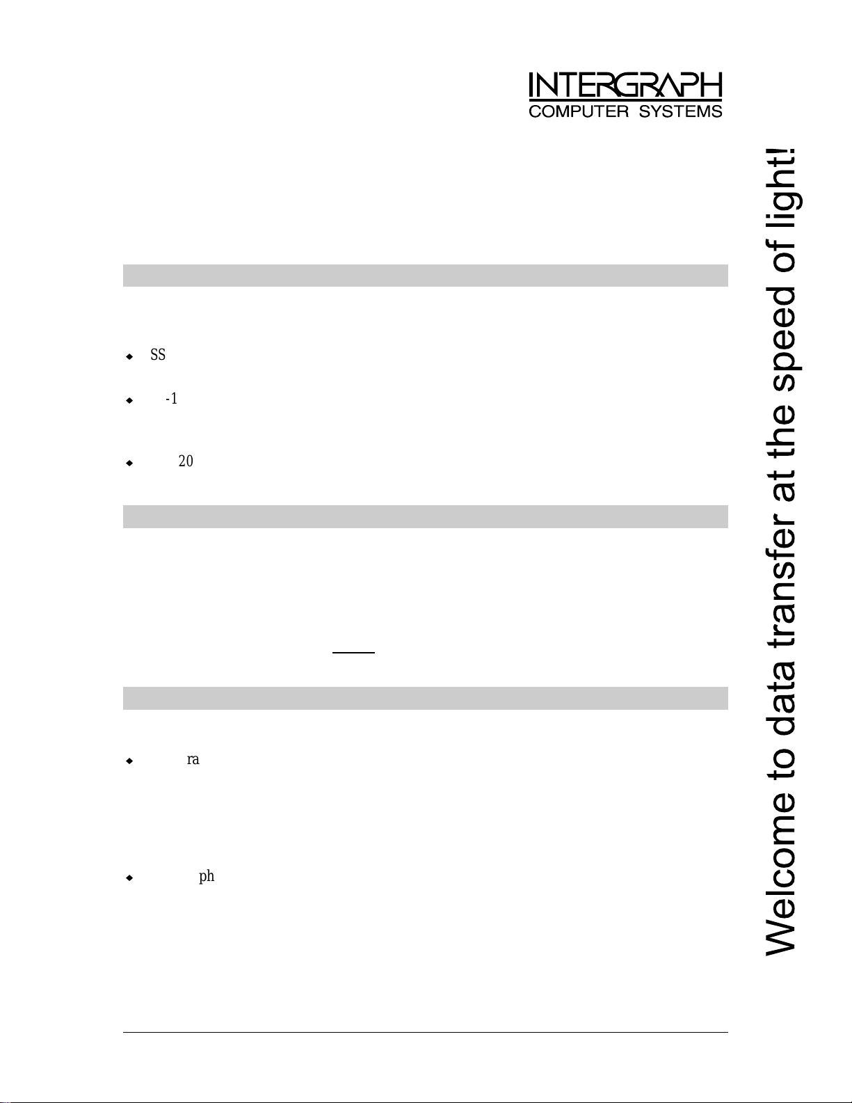
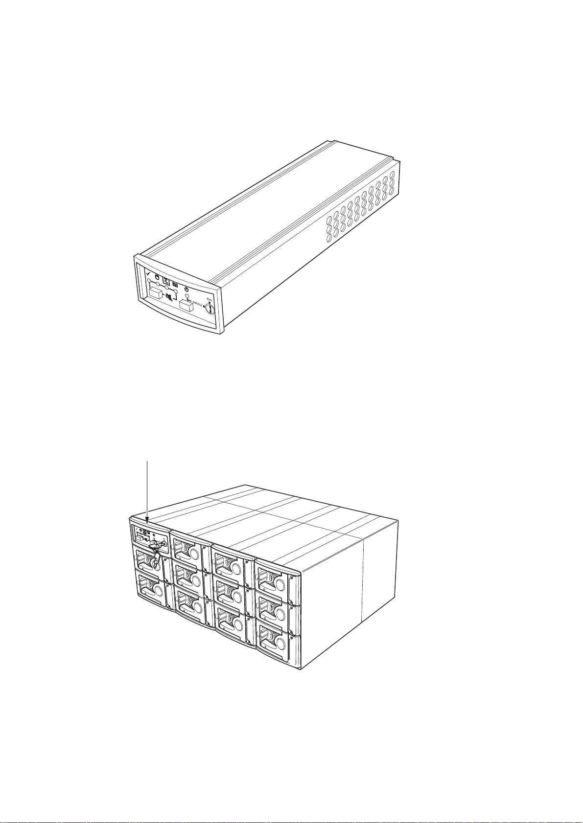
1.1 The SS-1200-FCAL System
.
Introduction
Figure 1–1 The SS-1200-FCAL System
1.2 The Enclosure Core Product
The SS-1200-FCAL design concept is b ased on a sub system to gether with a set of plug -in modules. T he Salient SS 1200-FCAL subsystem as supplied comprises:
• Chassis with Backplane installed.
• Power Supply/Cooling plug-in modules, in accordance with your required configuration (see Figure 1–4).
1
SS-1200-FCAL User Guide
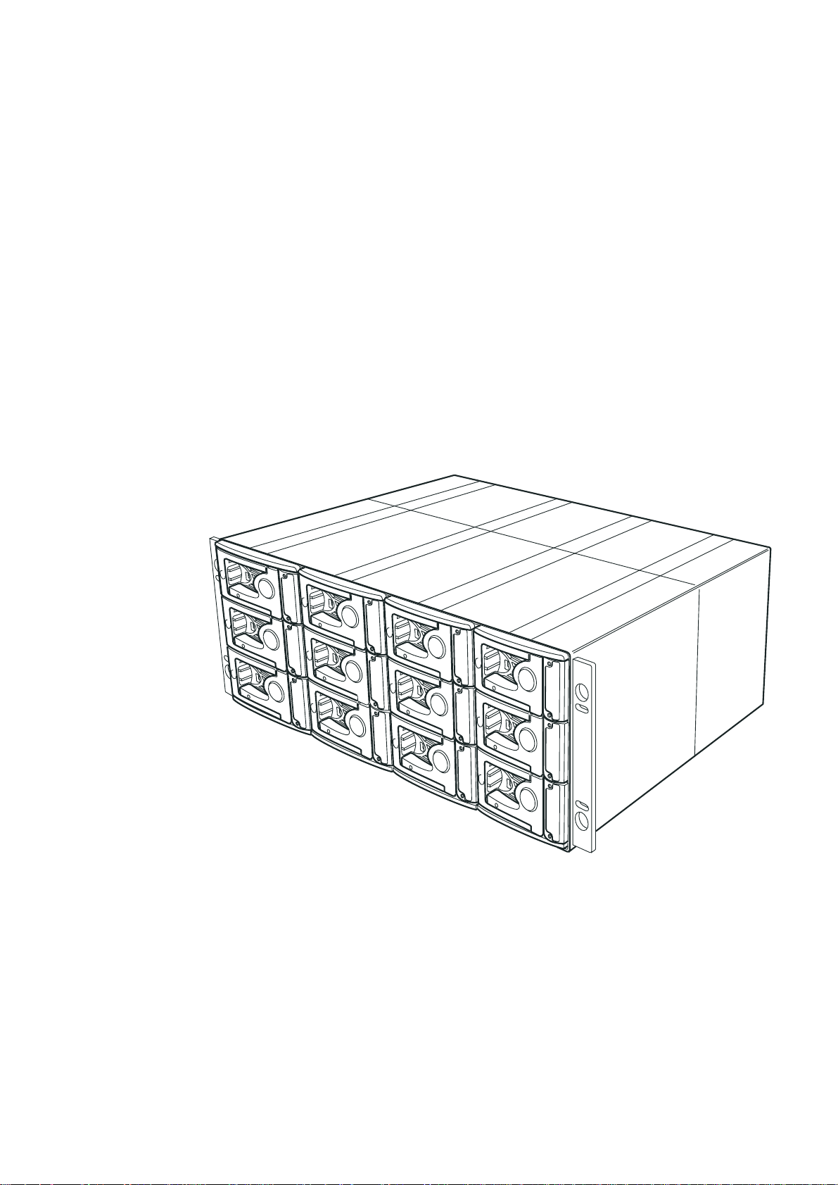
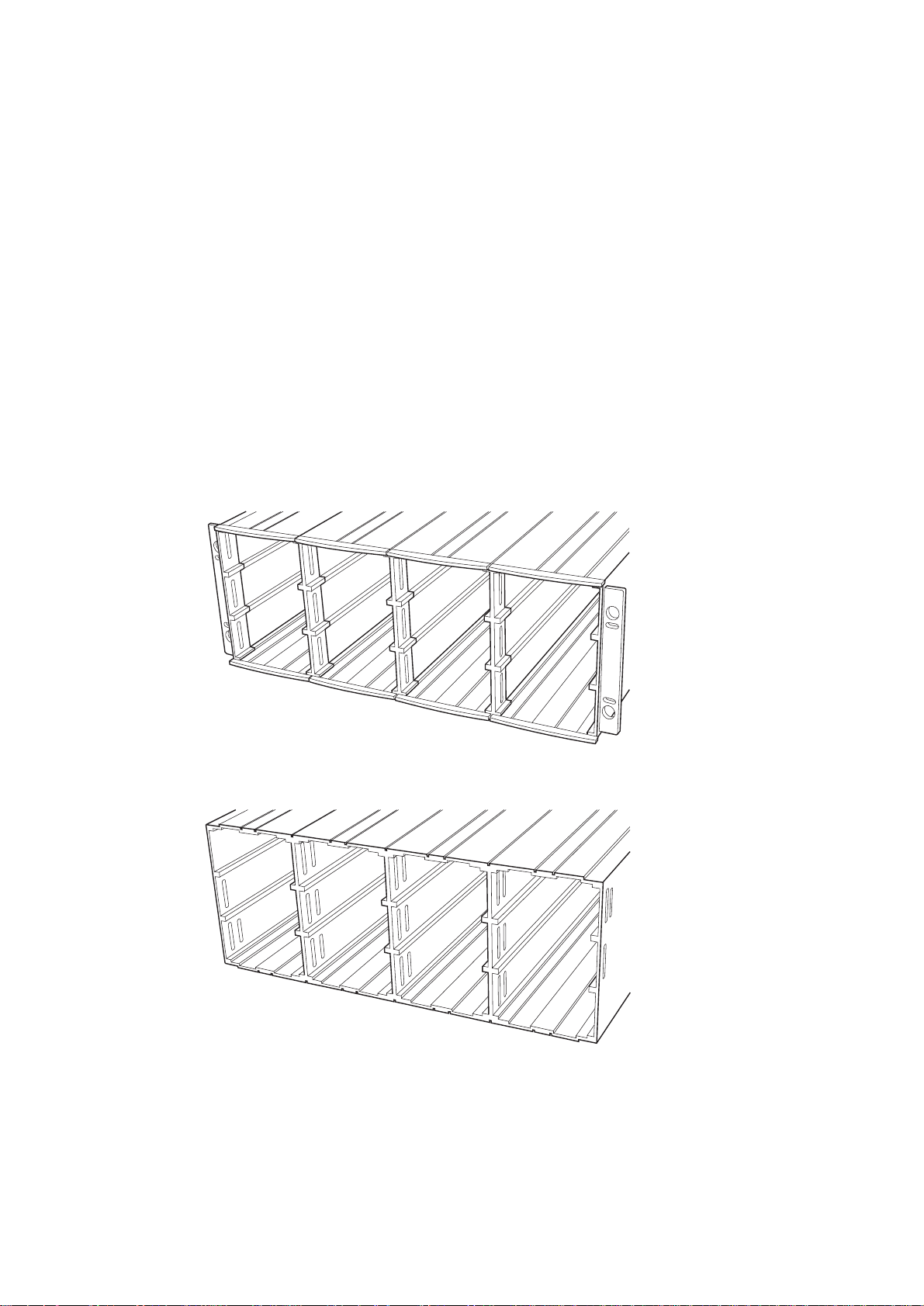
1.2.1 Enclosure Chassis
The chassis consists of two segmented chassis assemblies, constructed from a number of aluminum extruded
sections, with a Backplane PCB between them. The chassis assemblies each contain 12 'Bays', each of which
accommodates a plug-in m odule (la rger mod ules can be acc ommodate d using mult iple bay sp aces). The Backplan e
PCB provides logic level signal and low voltage power distribution paths. A SS-1200-FCAL chassis is shown in
Figure 1–2 and Figure 1–3.
• An Enclosure System Interface/Operators Panel (ESI/Ops) plug-in module (see Figure 1–5).
• Blank plates, as required to complete your required configuration and installation.
• FC-AL Drive Carrier Modules and associated front dummy fascia plates. (See Figure 1–10).
• FC-AL Input/Output Modules. (See Figure 1–11).
• A third Power Supply/Cooling Module may be required to support some 10 000 rpm disk drives.
• A Bay is defined as the space required to house a single 1.6" high 3.5 inch disk drive in its carrier module. e.g.
a 1 x 3 bay module wo uld take the space of 1 drive width by 3 drive bays high (in r a ck mount configuration).
• A 4 x 3 Chassis fitted with 19 inch Rack mounting features enabl es it to be fitted to standa rd 19 inch racks. It
uses 4EIA units of rack space.
Figure 1–2 Enclosure Chassis (Front)
Figure 1–3 Enclosure Chassis (Rear)
2
1.2.2 Tower Option
An optional tower kit is available, whi ch can be fitt ed to the rack chassis de scribed here. Se parate document ation is
provided with this option.
1.3 The Plug-in Modules
An SS-1200-FCAL En clo s ure r eq ui r es on e or mo r e of the follo w in g mo dules for normal operation:
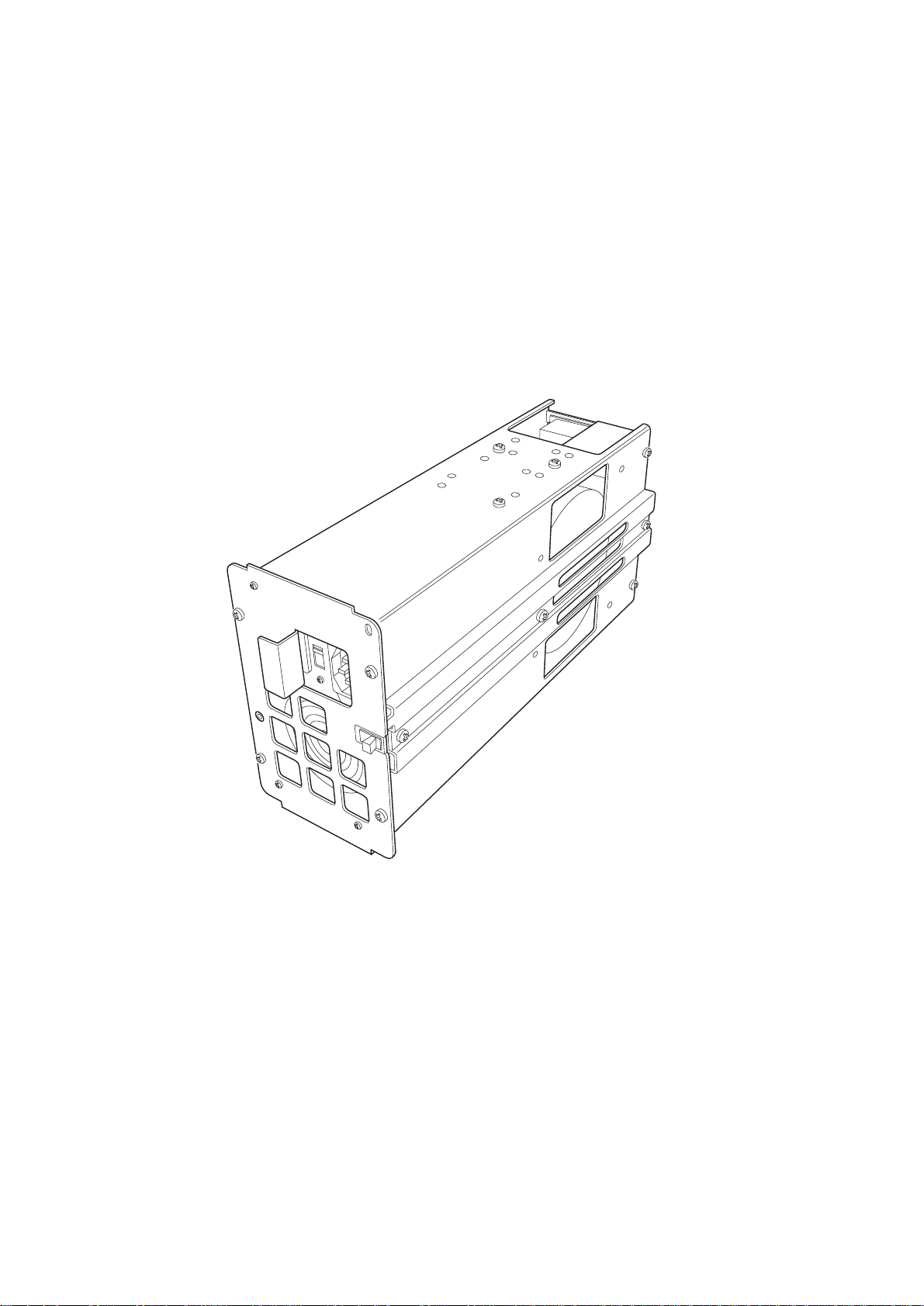
1.3.1 Power Su pp ly/Cooling Module
Two Power Supply/Coolin g modules are sup plied moun ted in the re ar of the enc losure as part of the subsyst em core
product. (Figure 1–4)
Introduction
Figure 1–4 Power Supply/Cooling Module
Up to three Power Supply/Cooling plug-in modules can be installed in the rear of the Enclosure.
PSU voltage operating ranges are nominally 115V or 230V AC, select ed by means of a switch on the front of the
PSU, shown in Figure 2–3.
.
An LED mounted on the fro nt panel of the Power Supply/Cooling Mod ul e (s ee Figure 2–3) indicates the stat us of
the PSU and the fans.
3
SS-1200-FCAL User Guide
1.3.2 Enclosure Syst em In ter fa c e/O per a tor s P ane l M odu le
Supplied as part of the Enclosure core product, a ty pical Enclosure System Interface/Operators (ESI/Ops) panel
module is shown in Figure 1–5.
Figure 1–5 ESI/Ops Panel Module
The(ESI/Ops) Panel provides the enclosure with a micro controller which is used to monitor and control all elements
of the Enclosure. Each element (Power, Cooling, Temperature, Device status) is interfaced to the processor using
2
C (I Square C) Bus.
an I
The ESI/Ops Panel is available as a plug-in module suitable for fitting in the enclosure either front facing (Figure
1–6) or rear facing (Figure 1–7).
ESI/Ops Panel
Figure 1–6 ESI/Ops Panel (Front mounting)
4

Introduction
ESI/Ops Panel
Figure 1–7 ESI/Ops Panel (Rear mounting)
Important Because the physical dimensions of the rear or front facing variants are different and they are not
interchangeable, they must each be ordered under their own unique part number.
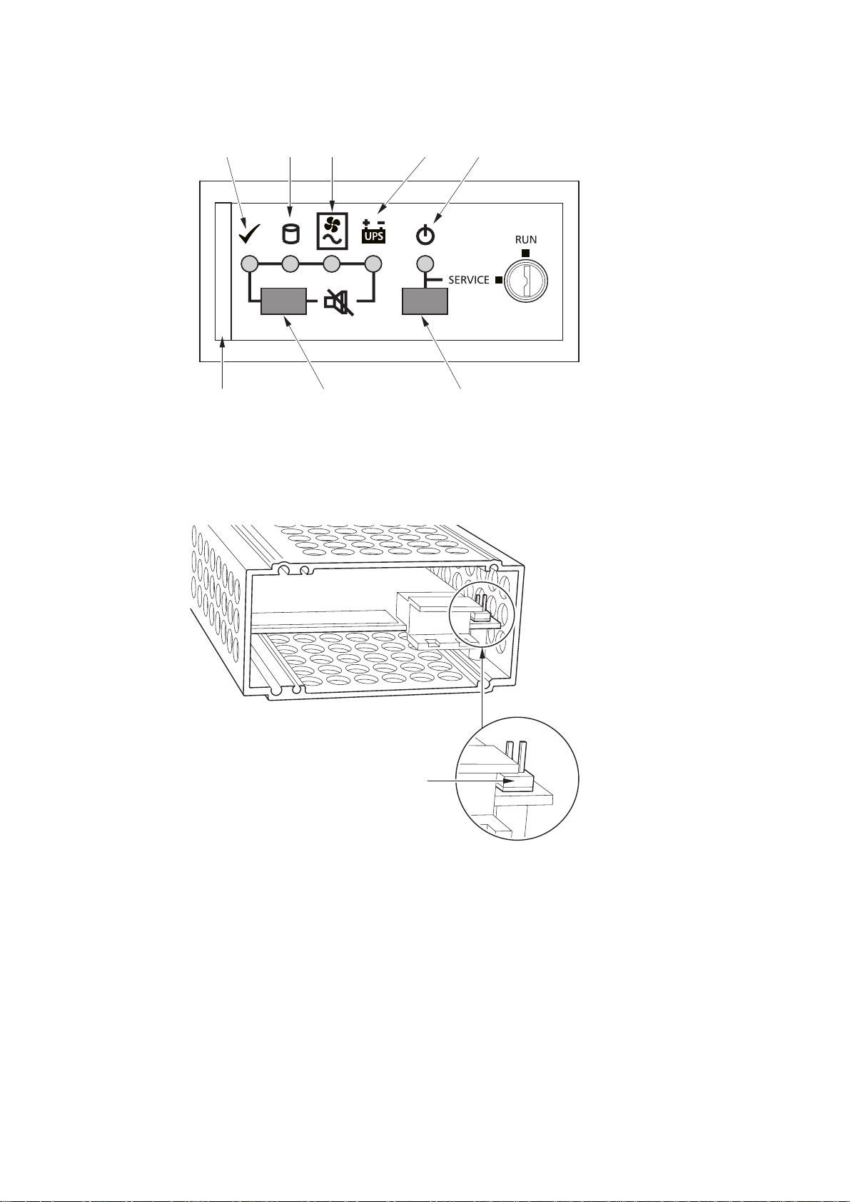
1.3.2.1 Ops Panel Indicators and Switches
The Operator Panel includes Light Emitting diodes (LEDs) which show the status for all modules and an Audible
Alarm which indicates when a fault state is present. The indicators and switches listed in the following table are
located from left t o right on the panel, as shown in Figure 1–8.
LED Indicators Symbol
System Status
Drive Status
Power & Cooling Status
UPS Status
Not Used
Power Standby Status
Switches
• Push-button Audi ble Alarm Mute
• Push-button Standby/Operational switch
• Rotary Keylock - Run/Service activate
5
SS-1200-FCAL User Guide
Figure 1–8 Ops Panel Indicators and Switches
1.3.2.2 Manual Spin up Jumper
System Drive Power/Cooling UPS Standby
Run/ServiceAlarm MuteSecuring Latch
A manual spin-up jumper can be fitted to the rear panel of the ESI/Ops module, it is used to disable the auto spin
start function. (Please refer to Section 2.3.5.2 and 2.3.5.3).
Manual Spin up Jumper
Figure 1–9 Manual Spin-up Jumper
6

1.3.3 Drive Carrier Modules
Please refer to separate installation guide for device specific information.
Figure 1–10 Drive Carrier Module
1.3.4 Loop Resiliency Circuit Input/Output Module (FC)
Introduction
Please refer to separate installation guide for details. (SS-1200-FCAL LRC I/O Module Installation Guide).
The FC-AL Backplane incorporates two independent loops formed by Port Bypass Circuits within the Loop
Resiliency Circuit (LRC) I/O modules. The LRC I/O module is shown in Figure 1–11.
The enclosure may obviously be configured with either 1 or 2 modules. If only 1 module is fitted this Must be
installed in middle Bay 3/2 as the Device ID thumbwheel switches only operate in this bay.
(Please refer to the separate LRC I/O module installation guide for details of the thumbwheel switches.
Figure 1–11 FC-AL LRC I/O Module
7
SS-1200-FCAL User Guide
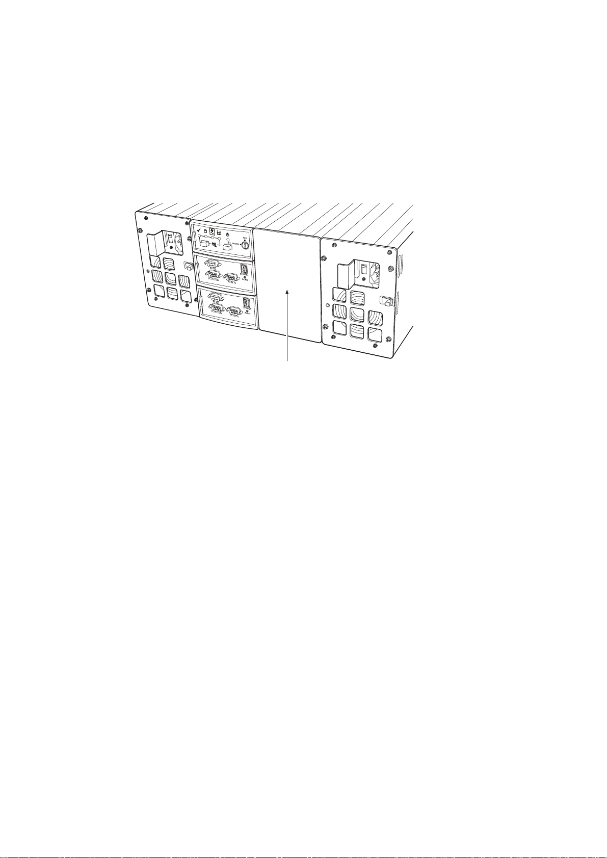
1.3.5 Blank Plates
Blank plates must be fitted over all vacant bays at the rear of the enclosure as shown in Figure 1–12. There are three
sizes of blank plate available:
– Single bay Rear blank pla te s
– 1x2 bay Rear blank pla te s
– 1x3 bay Rear blank pla te s
Blanking Plate
Figure 1–12 Enclosure with Blanking Plates
ANY
Warning Operation of the Enclo sure with
and the drives will not receive suffici ent coolin g. It is
before operating the unit.
blank plates or rear modules mis sing will disrupt t he airflow
1.3.6 Multiple Power Supply/Cooling Modules
If you have two or three Power Supply/Coo ling modules fitted , they operate toge ther. If one fails the ot hers maintain
the power supply and c ooling while you replace the faulty unit.
Module replacement should only take a few minutes to perform but must be completed within 20 minutes from
removal of the failed module. Alternatively, if there is no replacement module available, a blanking plate could be
fitted after removing the faulty module.
Note Three Power Supply/Cooling modules must be fitted if you are installing
drives consuming more than 21 watts (operational), e.g. 10 000 rpm 9GB HH drives.
1.3.7 Visibl e an d Audible Alarms
The functional modules have associated status LEDs. The ESI/Ops Panel shows a consolidated status for all
modules.
LEDs show constant green for good or positive indic atio n an d flas hin g gree n/r ed if non-critical conditions exist.
Constant Amber LEDs indicate there is a fault present within that module.
ESSENTIAL
that all rear apertures are filled
The ESI/Ops Panel also incorporates an Audible Alarm to indicate when a fault state is present and also an Alarm
Mute push-button.
Warning The Power Supply/Cooling mod ule is not an operator removable pa rt. It must only be removed by
a qualified service engineer who has knowledge of the hazards present within the module.
8

1.3.8 Anti-tamper Locks
Anti-tamper locks may be fit ted in th e d rive c a rrier h and les (Figure 1–13) and are accessed through the hole in the
lower part of the handle trim piece.These are provided to disable the normal “Push/Push” latch action of the handle.
To lock turn 90º
anti-clockwise
Introduction
Indicator Aperture
Figure 1–13 Anti-tamper Lock
1.4 SS-1200-FCAL Technical Specification
1.4.1 Dimensions
Rack Enclosure
Height 177mm, Widt h 446mm, Depth 586mm
Tower Enclosure
Height 570mm (including wheels), Width 265mm (a t base) 183mm (at top), Depth 592mm
1.4.2 Weight
Maximum Configuration 45 kg
Empty Enclosure (Ra c k ) 13 kg
Tower Conversion Kit 12 kg
PSU/Cooling Module 4 kg
1.4.3 Power
Voltage Range 100 - 120 or 200 - 240 VAC (switched)
Frequency 47-63 Hz
9

SS-1200-FCAL User Guide
Power consumption (Normal
operation 12 x 9GB Drives)
Power supply pe a k & op er a t i onal
currents (per supply)
Inrush Current 40/80 A @ 110/220VAC (25° cold start 1 PSU)
1.4.4 Power Cord
(minimum requirements)
Cord Type SV 0r SVT, 18 AWG minimum, 3 conductor
Plug 250V, 10A
Socket IEC 320, 250V, 10A
1.4.5 Environment
Table A–1 Ambient Temperature and Humidity
Operational 10°C to 40°C
800 VA
6.5 A Nominal @ 110V 10.5 A Peak @ 110V
Temperature Range Relative Humidity Max. Wet Bulb
(35°C if only 1 PSU/
Cooling Module)
20% to 80%
non-condensing
23°C
Non-Operational 0°C to +60°C 8% to 80%
non-condensing
Shipping -20°C to +60°C 5% to 100%
non-precipitating
Altitude 0 to 2133 m
Operational Shock Vertical axis 5g peak 1/2 sine, 10ms
Operational Vibration Random vibration power sp ectrum available on request
Non-Operational Shock 20g 20ms square wa v e
Acoustics Free standing enclosure declared ‘A’ weighted sound power level ≤6.8
Bels
Orientation & Mounting 19" Rack mount (4EIA Units)
• Rack Rails To fit 800mm depth Racks compliant with IEC 297
• Rack Characteristics Back pressure not exceeding 5 pascals (0.5mm water gauge)
Safety & Approvals CE, UL, cUL
• EMC EN55022 (CISPR - A), FCC A
10

1.4.6 Interfaces
Drive support See drive carrier specification
Attachment
Dual 12 drive FC-AL Loops
Passive Backplane with 2 Loop Resiliency Circuit (LRC) I/O Module.
FC-AL DB9 cables Maximum external cable length: Tx/Rx - 30m
MIA supported Tx/ Rx connector only
1.4.7 Drive Carrier Module Specification
Dimensions Height 48.8mm Width 125.35mm Depth 256mm
Weight 1.2kg (1.6” 9Gb drive)
Introduction
Tx only (daisy chain) - 15m
Operating
Temperature
Power Dissipation 30 Watts maximum
10° C to 40° C (when installed in a SS-1200-FCAL system enclosure)
1.4.8 FC-AL LRC I/O Module Specification
Connectors DB9 x 2
• 1 wired for Tx and Rx with Media Interface Adapter (MIA) support.
• 1 wired with Tx only, for daisy chaining loops,
– 1 x DB9 x RS232 (when installed in bay 3/2)
– 1 x DB9 x RPC (when installed in bay 3/3)
Current Limit 1A for MIA support .
11

SS-1200-FCAL User Guide
12

Chapter 2
Getting S tarted
2.1 Introduction
In this chapter, you are shown how to install your SS-1200-FCAL Enclosure and plug-in modules into an industry
standard 19 inch rack cabinet.
Getting Started
Caution When connecting up the SS-1200-FCAL subsystem, use only approved power cords.
2.2 Planning Your Installation
Before you begin installation you sho uld beco me famili ar with the configuration requirements of your SS-1200FCAL system, detailed in Table 2–1. The correct positions of each of the optional plug-in modules are shown in
Figure 2–1. Please refer to the accompanying FC-AL LRC I/O Module Installation Guide for details of FC-AL
configurations and installation.
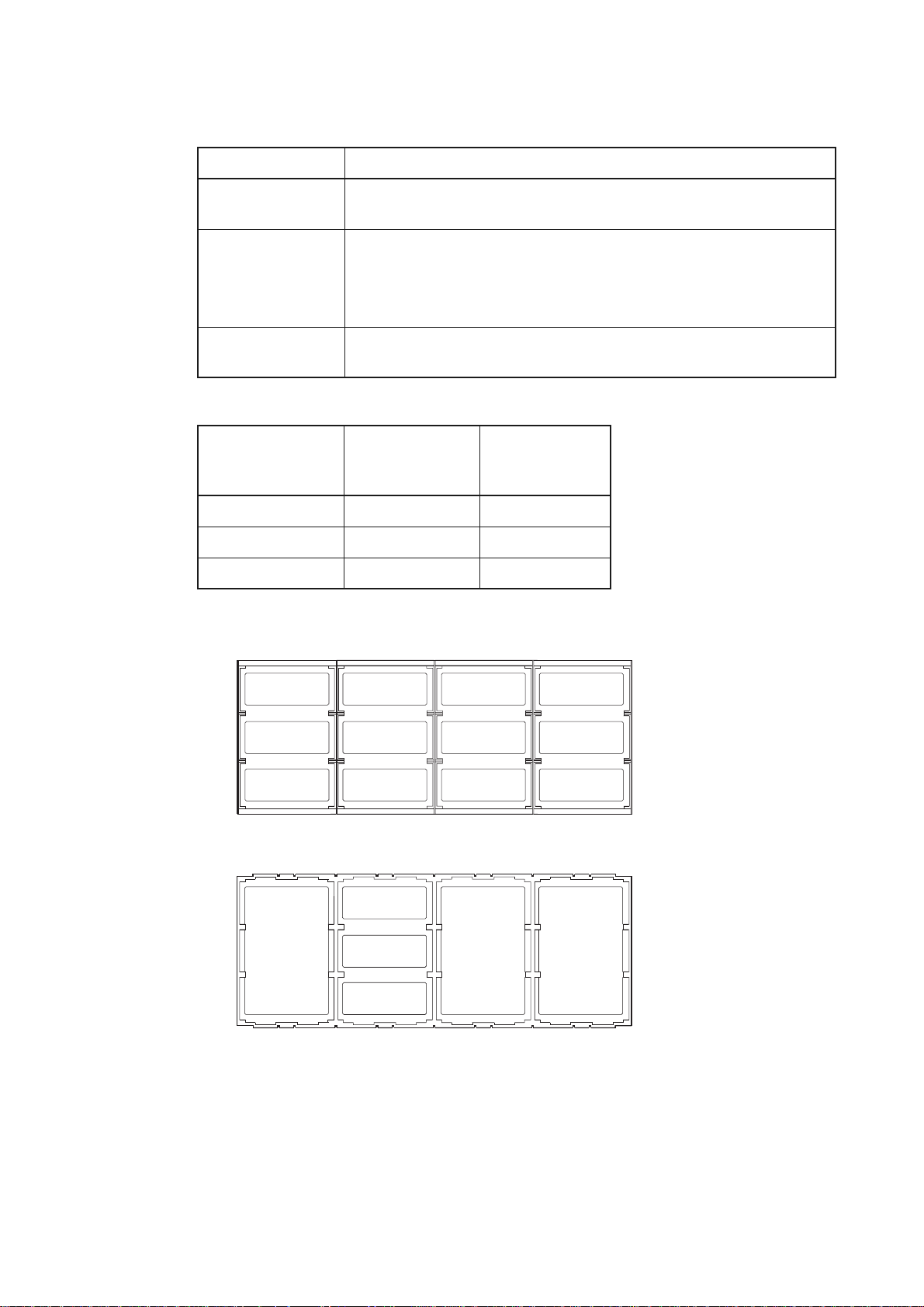
Table 2–1 SS-1200-FC AL Configuration
Module Location
Drive Bays ALL drive bays must be filled with either a drive carrier module, front dummy fascia
or (front) ESI/Ops Panel module (Bay 1/1 only), no bays should be left completely
empty.
Power Supply/Cooling
Modules
See Table 2-2
• Single Power S upply/Cooling module: if redundancy is NOT required and the
installed disk drives are low power, a single Powe r Supply /Cooling module mu st
always be fitted to rear Bay 2.
Single modules with a full compliment of drives will limit:
– the maximum operating temperature of the enclosure.
• Two Power Supp ly/Cooling modules: full p ower and cooling redundancy is
provided while a faulty module is replaced. Install the Power Supply/Cooling
modules in rear Bays 1 & 4. Refer to Table 2–2 for details of limitations
• Three Power Supply/cooling Modules: full power and cooling redundancy with
high power drives is maintai ned while a faulty module is replaced. Install the
modules in bay s 1, 2 and 4.
13
SS-1200-FCAL User Guide
Table 2–1 SS-1200-FCAL Configuration
Module Location
I/O Modules The Primary Module must be fitted in Bay 3/1. A second module (providing a second
loop path to all drives) may be fitted in Bay 3/3.
ESI/Ops Panel (variants
available for front or
rear facing)
• Front Facing - Install this in place of a drive in Front Bay 1/1.
Note: A special enclosure is required to support this configuration
• Rear Facing - Install in Rear Bay 3/2
Blank plates Rear blank plates MUST be fitted to ALL unused bays, there will be inadequate drive
cooling if any are left off.
Table 2–2 Minimum PSU Configurations
Average Operating
Drive Power
Minimum No. PSUs
(12 drives of same
No. PSUs with
Redundancy
type installed)
<13 1 2
14 - 21 2 2
22 - 30 3 3
Front View
Ops Panel (Front)
1
1
Drive or Facia
2
Drive or Facia Drive or Facia Drive or Facia
3
4
Drive or Facia Drive or Facia Drive or Facia Drive or Facia
2
3
Rear View
1
2
3
Drive or Facia
4
PSU/Fan
or
Blank
Drive or Facia
Ops Panel
LRC I/O 1
LRC I/O 2
Figure 2–1 Module Locations
Drive or Facia Drive or Facia
3
2
PSU/Fan
or
Blank
1
PSU/Fan
or
Blank
14

Getting Started
2.2.1 Enclosure Bay Numbering Convention
The enclosure bay numbering convention is shown in Figure 2–1. A Bay is defined as the space required to house
a single 1.6" high 3.5 inch disk drive in its carrier module. e.g. a 1 x 3 bay module would take the space of 1 drive
width by 3 drive bays high (in the rack mount configuration).
The SS-1200-FCAL subsystem is housed in a 4 x 3 enclosure, i.e. 4 bays wide by 3 bays high. The front bays are
numbered 1 to 4 from left to right, viewed from the front. The rear bays are numbered 1 to 4 from right to left,
viewed form the rear. Bays are numbered from 1 (top row) to 3 (bottom row). Module locations are identified from
a matrix of the top and side numbers, e.g. the front ESI/Ops panel should only be installed in front bay 1/1 (top left
when viewed from the front) while the rear ESI/Ops pa nel should be installed in rear bay 3 /1 (top, middle row, when
viewed from the rear).
2.3 Installation
Caution The SS-1200-FCAL Enclosur e with all its compo nent parts in stalled is too he avy for eas y instal lation into
a Rack cabinet. The following procedures describe the installation of the SS-1200-FCAL enclosure and
highlights any cri tical co-r equisite re quiremen ts and good handling p ractices which we e ncourage y ou to
follow so as to ensure that a successful installation is achieved in the easiest manner.
Warning Ensure that you have che cked and fitted a suitable anti-static wrist or ankle strap and observe all
conventional ESD precautions when handling SS-1200-FCAL modules and components. Avoid
contact with Backplane components and module connectors, etc.
2.3.1 Pre-Requisite s
The SS-1200-FCAL Enclosure is d esigned for installation into an industry standard 19 inch cabinet capable of
holding the unit.
• Minimum depth 580 mm from front flange to rear metal w ork (excludes rear cabling).
• Weight (35 to 45 kg dependent upon configuration) per enclosure.
• A minimum gap of 25mm (1inch) clearance between the rack cover and front of drawer; and 50mm (2 inches)
rear clearance between rear of drawer and rear of rack is recommended in order to maintain the correct air flow
around the enclosure.
• The rack should present a maximum back pressure of 5 pascals (0.5mm water gauge).
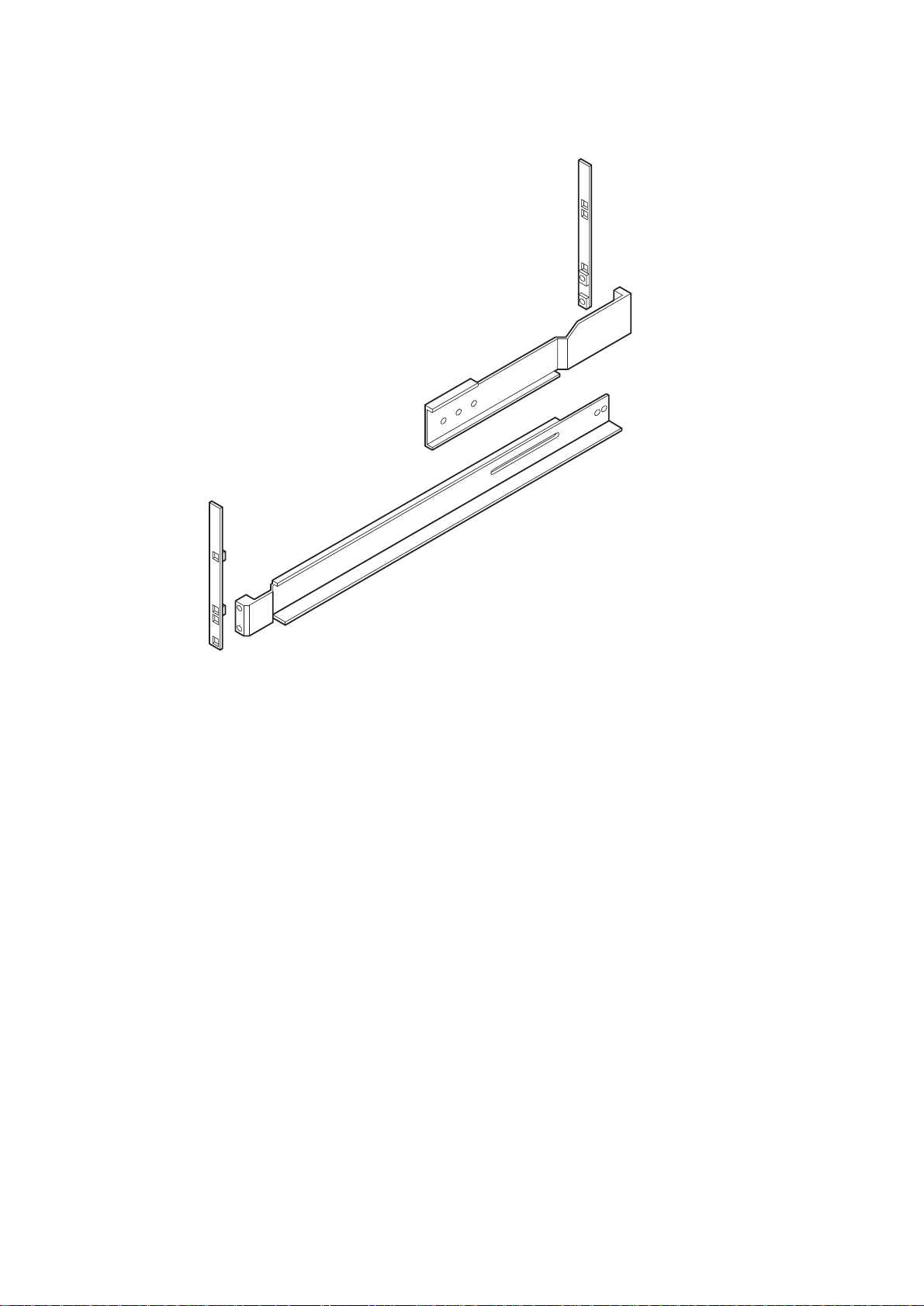
2.3.2 Rack Mounting R ail Kit
A set of mounting rails is available for use in 19 inch rack cabinets. These rails have been designed and tested to
handle the maximum enclosure weigh t and to ensure that multiple SS-12 00 enclosures may be installed with out loss
of space within the rack. Use of other mounting hardware may cause some loss of rack space.
The rack mounting rail kit also incorporates a rear hold down mechanism to ensure shock and vibration immunity.
Please contact us to ensure suitab l e mo unt rails are available for the Rack you are usin g.
15
SS-1200-FCAL User Guide
Figure 2–2 Rack Mounting Rail kit
2.3.2.1 Parts Check List
• Rack Mounting Rail Kit.
2.3.2.2 Installation Procedure
Please see detail drawings supplied with the rack mounting rail kit for assembly details.
2.3.3 Chassis Installation
2.3.3.1 Parts Check List
• Chassis (complete with Backplane installed but excluding all plug- in modules).
• Rack mount front flange mounting screws (4 off).
2.3.3.2 Procedure
1 Check for damage.
2 Slide the chassis assembly onto the rack rails until the front flanges engage on the rack. Ensure the chassis is
centrally located.
16
3 If in doubt about correct orientation, the drive bays (at front) should have their black drive connectors toward the
bottom of each bay.

Getting Started
4 If supplied, fit the rear hold down brackets at the rear of the unit (4 screws) do not tighten.
5 Screw the 4 front rack mount screws through the flanges and tighten.
6 If supplied, tighten the rea r hold down brack et ensuring the bracket is in tigh t contact to bo th the side and to p of the
chassis to avoid any movement of the chassis in the rack.
2.3.4 Power Supply/Cooling Module Installation
2.3.4.1 Parts Check List
• 1, 2 or 3 Power Supply/Cool ing Modules.
2.3.4.2 Procedure
1 Check for damage, especially to the rear connector on the supply.
Warning Handle the module c arefully and avo id dama ging the connec tor pins. Do not insta ll the m odule if
any pins appear to be bent.
2 Set the red Voltage Range selector switch (Figure 2–3) adjacent to t he mains inlet socket to either 115V or 230V as
required for your installation.
Hole for Grounding
Screw
PSU Range
Selector Switch
LED
Retention Latch
Figure 2–3 Power Supply Range Selector Switch
Warning The Power supplies are
PSU.
3 Install the Power Supply/Cooling modules in the rear of the chassis in the positions indicated below. (Please refer
to Table 2–1 for Configuration details).
• Single Power Supply/Cooling module - Install in Bay 2
• 2 Power Supply/Cooling modules - Install in Bays 1 & 4
• 3 Power Supply/Cooling modules - Install in Bays 1, 2 & 4
NOT
auto-ranging, failure to select the correct range
WILL
damage the
17

SS-1200-FCAL User Guide
Figure 2–4 Power Supply/Cooling Module Location (Bay 4 shown)
4 Hold the latch while pushing the module gently home into the bay, ensure that it is fully engaged and that the
retention latches are engaged into the chassis (See Fig ure 2–5).
PSU/Cooling Module Bay
18
Figure 2–5 Installing a Power Supply/Cooling Module in Bay 4
5 Fit and tighten the retaining screw on the front panel to secure the module (see Figure 2–6).

Getting Started
Figure 2–6 Fitti ng the Earth Screw
2.3.5 ESI/Ops Panel Module Installat ion
2.3.5.1 Parts Check List
• Front ESI/Ops Panel Module OR Rear ESI/Ops Panel Module
• Ops panel key(s)
• Jumper 2 pin
2.3.5.2 Manual Spin-up Jumper
This jumper is provided to disable the auto spin start functi on.
Caution If this jumper is fitted the Enclosure services will not attempt to auto start any of the drives in the
enclosure.
2.3.5.3 Jumper Installation Procedure
1 The jumper is fitted at the rear of the ESI/Ops Panel module, to access it the module must be removed from the
enclosure.
2 Fit the jumper on the 2 pins (designated LK1) on the ESI motherboard to disable the auto spin start function.
Table 2–3 Jumper Connections
ESI Motherboard Pin Condition
LK1 Fitted - Manual start, no auto spin-up
Not Fitted - Auto spin-up
LK2 Reserved: DO NOT USE
19

SS-1200-FCAL User Guide
Manual Spin up Jumper
Figure 2–7 Manual Spin -up Jumper
Figure 2–8 Installing the ESI/Ops Panel (Front Mounting)
20

Figure 2–9 ESI/Ops Panel: Front Installation
Getting Started
Figure 2–10 Installing the ESI/Ops Panel (Rear Mounting)
2.3.5.4 ESI/Ops Panel Installation Procedure
Caution Check that the Ops panel keys are included with the module. If they cannot be accounted for they may
have been discarded with the packaging.
Install the module by sliding into the correct Bay (1/1 at front or 3/1 at rear, refer to Table 2–1) ensuring the module
has docked with the connector and the retention clip has engaged with the chassis.
21

SS-1200-FCAL User Guide
Figure 2–11 ESI/Ops Panel: Rear Installation
2.3.6 Other Plug- in Mo du les
Please refer to the relevant SS-1200-FCAL Installation Guides for information on the ILRC I/O Module and Drive
Carrier Module installation procedures.
Important Ensure that all plug-in modules are installed
2.3.7 Interface Ca bling
Please refer to the SS-1200-FCAL LRC I/O Module Installation manual for details of interface cable attachments.
2.3.8 Blank Plates
BEFORE
fitting blanking plates (see Section.2.3.8).
22
Blanking Plate
Figure 2–12 Typical Blanking Plate Installation

2.3.8.1 Parts Check List
where applicabl e :
• Single bay Rear B l a nk pl at es
• 1x2 bay Rear Blank plates
• 1x3 bay Rear Blank plates
Getting Started
Warning Operation of the enclosure with
and the drives will not receive su fficient co oling. It is
before operating the unit.
2.3.8.2 Procedure
Clip the correct size blank plates into the rear bay apertures as required.
ANY
blank plates or rear modules missing will disru pt the airflow
ESSENTIAL
that all rear apertures are filled
2.3.9 Power Cord C onn ection
Warning Ensure that you select the correct voltage range
connecting the power cords. The Power supplies are
correct range
2.3.9.1 Parts Check List
• Trifurcated power cord
• Power cord to requisite local standards
2.3.9.2 Procedure
1 Attach the Triifurcated power cord to the Power Supply/Cooling Modules,
2 Attach the power cord to the in-line IEC connector in this cord.
WILL
damage the PSU.
Caution These power splitting cables are provided so that the system is operated from a SINGLE power source
thus providing a single point of disconnect. They must always be used. Do not connect to the Power
source until installation is complete.
on the
Power Supply/Cooling module
NOT
auto-ranging, failure to select the
BEFORE
3 A STANDBY LED on the ESI/Ops panel indicates whether AC mains power is present.
Caution The power connections must always be disconnected prior to removal of the Power Supply/Cooling
module from the enclosure.
The On/Off switches on each Power Supply/Cooling module Only isolate the power from that module.
Any other power supply/cooling modules will remain active.
2.3.10 Ground ing Ch ecks
Perform these checks to ensure that a safe grounding system is provided.
• If a rack distribution system is being used.
– Ensure power is removed from the rack.
– Connect the SS-1200-FCAL power cord t o t he rack distribution and the enclosure.
• If a direct connection is made with the SS-1200-FCAL power cord, ensure that it is connected to the enclosure.
Warning Some electrical circuits could be damaged if external signal cables or power control cables are
present during the grounding checks.
• Check for continuity between the earth pin of the IEC 320 connector on one of the Power Supply /Cooling
modules and any exposed metal surface of the SS-1200-FCAL enclosure.
23

SS-1200-FCAL User Guide
24

Chapter 3
Operation
3.1 Before You Begin
Before powering up the enclosure please ensure that all the modules are firmly seated in their correct bays and that
Blank plates are fitted in any remaining bays.
Operation
3.2 Power On
Do not operate the subsystem until the ambient temperature is within the specified operating range. If the drives
have been recently installed ensure they have had time to acclimatize before operating them.
Warning Check that the Voltage sele ctor switch on the rear of eac h Power Supply/Coo ling module has the
correct voltage range (115 V or 230V) selected
Note Please refer to Section 3.3 for details of the Operator Panel LEDs and related fault conditions.
Before
3.2.1 Standby Mode
Use this mode of operation on initial installation or whenever manual control of the enclosure power is required.
Follow the procedure below to power up the enclosure.
1 Set the Run/Service keyswitch on the Ops Panel (Fitted either in the fro nt or rear of the enc losure) to the SE RVICE
position.
2 Apply AC Mains Power to the enclosure.
3 The STANDBY LED on the Ops Panel should be lit (Green).
4 Press and hold the STANDBY push-button switch (positioned directly beneath the STANDBY LED) for >1.5
seconds, until the enclosure power is activated.
The Power Supply/Cooling LED on the Ops Panel should be lit (Green) when the enclosu re power is activate d (and
if auto start mode is set the disk drive motors should start).
applying power to the equipment.
5 The enclosure will toggle between STANDBY Mode (all drives will be powered down) and OPERATION Mode
whenever the Standby push-button is depressed. Press and hold the STANDBY push-button switch for >1.5 seconds
to switch off the enclosure power.
25

SS-1200-FCAL User Guide
Notes 1 All LEDs on the Ops panel should be lit Green at po wer up to ind ic a te tha t th e system is fu nctio ning correctly.
(The UPS LED will be lit Green with or without UPS fitted.)
2 If any alarms sound shortly after power on then a problem exists and the procedure in , ”Troubleshooting and
Problem Solving” should be followed.
Important If mains power is lost for any reason, the enclosure will power down in STANDBY Mode and the
STANDBY push-button must be pressed to power the enclosure up.
Turning the Keyswitch from Service to Run positions will activate the power. Returning it to the
Service position, the enclosure will remain powered ON until the STANDBY push-button is
depressed
To protect against ac cide ntal operation, the STANDBY push-button is designe d with an inherent
delay in operation. The button must be depressed for approximately 1 second before the power
is enabled or disabled.
3.2.2 Run Mode (Nor mal Op er at i on)
Use this mode in an un-attended installation where the enclosure is required to default to Power On whenever AC
mains power is present.
1 Turn the Run/Service keyswitch to the Run position.
2 The Standby button is now d isabled. If mains powe r is interrupted th e system will return t o the Power On c ondition
when mains power is restored.
3 Follow the procedure for powering on as described in Section 3.2.1 above.
Important The Run/Service keyswitch may be turned to the Service position at any time, the enclosure will
remain powered on until the Standby push-button is pressed.
3.3 Operator Panel LEDs
The Ops Panel LEDs are shown in Figure 3–1.
System Drive Power/Cooling UPS Standby
26
Run/ServiceAlarm MuteSecuring Latch
Figure 3–1 Ops Panel LEDs

Under Normal conditions the following LEDs should all be illuminate d const ant GREEN
LED Indicators Symbol
System Status
Drive Status
Power & Cooling Status
UPS Status
Operation
Power Standby Status
Switches
• Push-button Audi ble Alarm Mute
• Push-button Standby/Operational switch
• Rotary Keylock - Run/Service activate
If a problem is detected the ESI processor will change the color of the relevant LED to AMBER.
For non critical conditions the LEDs flash GREEN.
Refer to , ”Troubleshooting and Problem Solving” for details of any fault indication. Table 3–1 summarizes the
LED Fault conditions.
.
Table 3–1 LED Fault Conditions
Indicator Status
SYSTEM LED FLASHING GREEN /AMBER - A Configuration error has been detected.
AMBER - System failure. The ESI processor has detected a problem.
Disk Drive(s) LED AMBER - One or more drive(s) has a fault (see drive LED information).
Power Supply/Cooling LED AMBER - A problem with one of the Power Supply/Cooling modules (Each
module incorporates its own GREEN/AMBER LED).
STANDBY LED AMBER - Enclosure shutdown has occurred due to machine overheating.
3.4 St arting the Drives
Unless otherwise selected during instal lation, all drive s in the enclo sure should autom atically start th eir motors in a
delayed sequence after power is applied. If this has not occurred one of the following conditions may exist.
27

SS-1200-FCAL User Guide
3.4.1 Disk Drives LEDs
Each drive carrier incorporates two indicat ors, an upper (GREEN) and lower (AMBER). In normal operation the
Green LED will be ON and will flicker as the drive operates.
3.5 Power Do wn
to power the enclosure down,
either
or
• The 'Manual start' option jumper has been fitted to the ESI/Ops panel module during installation, thus
disabling the drive auto start functio n. If m anual sta rt ha s been selec ted, then Driv e Start com man ds must b e
issued to each drive in order to start their motors
• There is a power problem (an alarm and power fault indication would normally be active).
• Place the Enclosure in STANDBY Mode (See Service Mode operation above).
• Remove AC Mains at the power source
28

Chapter 4
T roubleshooting and Problem Solving
4.1 Overview
The SS-1200-FCAL Enclosure includes a processor and associated monitoring and control logic to enable it to
diagnose problems within th e enclosure’s power, cooling and drive systems.
Troubleshooting
The Enclosure Services Processor is housed along with the Operator Panel either in the front or rear of the enclosure.
The sensors for power, cooling and thermal conditions a re housed within the P ower Supply/Cooling modules. T here
is independent monitoring for each unit.
If a fault is indicated on the Operator Panel (Ops Panel), please refer firstly to Table 4–1 and then to the section
referenced within that table.
4.2 LEDs
Green LEDs are always used for good or positive indication, flashing Green/Amber if non-critical conditions exist.
Amber LEDs indicate there is a critical fault present within the module.
The Operator Panel displays the ag gre g ated st atus of a ll th e mo du les. Th e Ops Pa nel LEDs a re shown in F i gu r e 4–
1 and the LED status conditions are listed in Table 4–1
Table 4–1 Ops Panel LED Status
LED Off Green Steady Green/Amber
System Status Power off or
Standby
ESI functions all
OK
.
Flashing
System
Configuration
Error
Amber Steady Section
Ref No.
ESI / I2C
function failure
4.5.1
Drive Status Power off/
Standby
No fault reported Not used Drive fault
reported
4.6
29

SS-1200-FCAL User Guide
Table 4–1 Ops Panel LED Status
LED Off Green Steady Green/Amber
Flashing
Power/ Cooling Power off/
Standby
UPS Status
Standby No AC supp ly Standby OR
System Drive Power/Cooling UPS Standby
All PSUs & Fans
OK
Not used on FC-AL Enclosure
Power good
Not Used Any PSU or Fan
Not Used Machine in
Amber Steady Section
Ref No.
4.5.2
fault
4.5.4/
Standby due to
ESI Thermal
Shutdown
4.5.5
30
Run/ServiceAlarm MuteSecuring Latch
Figure 4–1 Ops Panel LEDs and Switches
For details on how to remove and replace a module see Section 4.9.
Warning Whenever replacing a modu le NEVER le ave an EM PTY s pac e in th e rea r of the e nclo sure, obtai n
a replacement before removing the problem part.
4.3 Audible Alarm
The Operator Panel also includes an Audible Alarm which indicates when a fault state is present. The following
conditions will activate the Audible Alarm:
•Drive Fault
•Fan slow
• Voltage out of range
• Over temperature
• Thermal overrun
• UPS two minute warning
• System fault

4.3.1 Audible Alarm Mute
When the Audible Alarm sounds, it may be muted by pressing the Alarm Mute push-button until a double beep is
heard (approximately 1 second). The Alarm Mute push-button is located beneath the i ndicators on the Operator
Panel (see Figure 4–1).
When the alarm is muted it will continue to sound with short intermittent bleeps to indicate that a problem still
exists, It will be silenced when all problems are cleared. (See also Thermal Shutdown states, Section 4.5.5).
4.4 Test Mode
A Test Mode is available whenever there are no faults present within the sub-system. In this mode the Amber an d
Green LEDs on each of the drive carrier modules are flas hed on and off in sequence.
To Activate Test Mode (with no other faults present)
Press the Alarm Mute push-button until a double beep is heard. The LEDs will then flash until reset, either by
pressing the Alarm Mute push-button again or if any actual fault occurs.
4.5 Troubleshooting
Troubleshooting
The following sections describe common problems, with possible solutio ns, which can occur with your SS-1200FCAL system.
4.5.1 System Faults
Symptom Cause Action
1 The SYSTEM LED will
illuminate AMBER
2 Audible Alarm sound
The ESI processor has detected
an internal fault (e.g. failure of
an internal communications
path)
1 Check for other AMBER LED
indications on the Power Sup ply/Cooling
modules. If there is a PSU error present
there may be a communications problem
with that Power Supply/Co oling module.
Remove and then re-fit the module, if th e
problem persists then change th e module.
2 Check for other AMBER LED
indications on the drives carriers. If none
are evident then there may either be an
ESI processor problem or a Backplane
problem.
3 Change the ESI/Ops Panel module (see
4.9.2).
Note See also Section 4.5.5.
31

SS-1200-FCAL User Guide
4.5.2 Power Suppl y/C oo li n g Fa ults
Symptom Cause Action
1 Operator Panel Power
Supply/Cooling LED
AMBER (~ and Fan
Symbol).
2 A AMBER LED on one
or more Power Supply/
Cooling Modules.
3 Audible Alarm Sounding.
4.5.3 Thermal Control
The SS-1200-FCAL Enclosure uses extensive thermal monitoring and takes a number of ac tions to ensure
component temperatures are kept low and also to minimize acoustic noise.Air flow is from front to rear of the
enclosure.
1 Any power fault.
2 A fan failure.
3 A thermal condition which
could cause PSU
overheating.
1 Check Power On/Off Switch on rear of
Power Supply/Cooling module is
switched ON.(not accessible on later
models)
2 Check AC Mains Connections to
Power Supply/Cooling module is live.
3 Check PSU Voltage Range selector
switch is correctly set.
4 Disconnect the Power Supply/Cooling
module from mains power and remove
the module from the system, Reinstall: if problem persists, replace
Power Supply/Cooling Module.
5 Reduce the ambient temperature.
Symptom Cause Action
If the ambient air is cool (below
25 °C) and the fans are
observed to increase in speed
then some restriction on airflow
may be causing additional
internal temperature rise.
Note: This is not a fault
condition.
The first stage in the thermal
control process is for the fans to
automatically increase in speed
when a thermal threshold is
reached. This may be caused by
higher ambient temperatur es in
the local environment and may be
perfectly normal.
Note: This threshold changes
according to the number of drives
and power supplies fitted.
1 Check the installation for any airflow
restrictions at either the front or rear of
the enclosure. A minimum gap of
25mm at the front and 50mm at the rear
is recommended.
2 Check for restrictions due to dust build-
up, clean as appropriate.
3 Check for excessive re-circulation of
heated air from rear to the front, use in
a fully enclosed rack installation is not
recommended.
4 Check that all Blank plates/modules are
in place.
5 Reduce the ambient temperature.
32

4.5.4 Thermal Alarm
Symptom Cause Action
Troubleshooting
1 Operator Panel Power
Supply/Cooling LED
AMBER (~ and Fan
Symbol).
2 An AMBER LED on
one or more Power
Supply/Cooling
Modules.
3 Audible Alarm
Sounding.
4 Air temperature exiting
PSU above 55°C.
4.5.5 Thermal Shutdown
If the internal temperature
measured in the airflow through
the enclosure exceeds a pre-set
threshold a thermal alarm will
sound.
1 Check local ambient env ironment
temperature is be lo w the up pe r 40°C
specification.
2 Check the installation for any airflow
restrictions at either the front or rear of
the enclos ure. A mi nimum ga p of 25mm
at the front and 50mm at the rear is
recommended.
3 Check for restrictions due to dust build-
up, clean as appropriate.
4 Check for excessive re-circulation of
heated air from rear to the front, use in a
fully enclosed rack installation is not
recommended.
5 If possible shutdown the enclosure and
investigate the problem before
continuing.
Symptom Cause Action
1 ALL AMBER LEDs
on the Operator Panel
and on ALL drive bays
illuminated flash.
2 Audible Alarm sounds
almost continuously
and cannot be muted.
Important: The Enclosure will SHUTDOWN 10 seconds aft er the abov e Symptoms are obse rved. This will
leave the following indications active.
1 STANDBY LED
Illuminated AMBER
2 Enclosure power ed off
At a higher threshold than the
Thermal Alarm (this should already
have been activated) the Enclosure
is programmed t o shutdown in
order to protect itself and the disk
drives from damage.
OR - All fans have failed.
OR - Only 1 fan operating and the
internal temperature is 40° C or
above.
1 Clear the source of the overheating
2 Leave for a period to cool down.
3 Remove AC Mains power from the enclosure for at least 30 seconds to reset
the shutdown condition
4 Re-start enclosure using normal operating procedure
5 Check for re-occurring cooling faults (especially fan failure).
1 Check for airflow restrictions.
2 Check Power Supply/Coo ling module
faults.
3 Check for excessive local temperatures.
33

SS-1200-FCAL User Guide
4.6 FC-AL Drive Carrier Modu le Fa ult s
Disk drive status is monitored by a Green LED and an Amber LED mounted on the front of each Drive Carrier
Module, providing the following ind ic at ion s:
LED Condition Status Action
GREEN OFF • No drive fitted
AMBER and GREEN Flashing Test Mode active Press Alarm Mute button to reset
AMBER Standby Drive Fault see device details
4.7 Dealing with Hard ware F ault s
OR
• Spinup (wait 30 seconds)
ON/Flickering Power on/operating
test mode.
Ensure that you hav e obtained a replacement module of the same type before removing any faulty module.
Warning If the SS-1200-FCAL subsystem is powered up and you remove any module, replace it
immediately. If the subsystem is used with modules or blanking plates missing for more than a
few minutes, the Enclosure can overheat, causing power failure and data loss. Such use will
invalidate the warranty.
• Replace a faulty drive with a drive of the same type and capacity.
• All drive bays must be fitted with either a Drive Carrier Modu le or a front dummy fascia in ord er to maintain
a balanced air flow.
• All the supplied plug-in power supply units, electronics modules and Blank plates must be in place for the air
to flow correctly around the cabinet.
4.8 Continuou s Operat ion Durin g Rep lacem ent
Depending on how the subsystem is set up, if a disk unit fa ils, it c an n ormally be re pl aced with o ut inte rru pting the
use of the system.
In addition, each enclosure can contain one, two or three power supply units, any of which can maintain power and
cooling to the subsystem while one of the others is replaced.
4.9 Replacing a Modu le
34
Please refer to Chapter 2, ”” for information on the initial installation of the plug-in modules in the SS-1200-FCAL
enclosure.
Warning Observe all conventional ESD precautions when handling SS-1200-FCAL modules and
components. Avoid contact with Backplane components and module connectors, etc.

Troubleshooting
4.9.1 Power Supp ly/Cooling Module
4.9.1.1 Removing the Module
Warning Do not remove the faulty Power Supply/Cooli ng module unless you have a replacement unit of the
correct type ready for insertion.
If a power supply unit or its fan is faulty, you must replace the whole power supply/cooling module.
If you have two o r thre e powe r supply unit s instal led, yo u c an cont inue workin g while repl acing the fa ulty module.
1 If you have more than one power supply unit installed, make sure you identify the faulty module correctly.
2 Remove the power cord from the faulty Power Supply/Cooling module.
3 Remove the earth screw and washer from the module front panel.
4 Release and hold the retention l at ch.
5 Grip the metal flange on the power supply unit front panel firmly between finger and thumb and slide the unit out
of the Enclosure bay (Figure 4–2).
Figure 4–2 Removing a power supply/Cooling module
4.9.1.2 Inserting the Module
1 Push the replacement modul e ge ntly ho me into the bay, e nsure th at it is fully enga ged a nd tha t the re tention latc hes
are engaged into the chassis.
2 Fit and tighten the earth screw and washe r on the front panel to secure the module (Figure 4–3).
.
3 Check that the correct voltage range has been selected.
4 Insert the power cord.
Note The alarm will sound until the new Power Supply/Cooling module is operating correctly.
35

SS-1200-FCAL User Guide
Figure 4–3 Fitting the Grounding Screw
4.9.2 ESI/Ops Panel Module
4.9.2.1 Removing the Module
Important This module is designed for Hot Plug replacement. In order to ensure that there is no loss of
system availability during replacement, the enclosure DEFAULT state with the ESI module
removed is Power On.
1 Release the catch on the side of the ESI/Ops Panel module.
2 Grip the front panel surroun d or the key (turned t o the Service position0 firmly and slide the uni t out of the enclos ure
bay.(Figure 4–4)
3 The subsystem must not be run for extended periods without the ESI/Ops Panel module being in place.
36
Figure 4–4 Removing an ESI/OpsPanel Module (Front Mounting)

Troubleshooting
4.9.2.2 Inserting the Module
Install the module by sliding into the correct bay (1/1 at front or 3/1 at rear) ensuring the module has docked with
the connector and the retention clip has engaged with the chassis. (Figure 4–5)
Caution TheESI/Ops panel module variants are not interchangeable, a front mountied module cannote be
installed in the rear mounting position and vice versa.
Figure 4–5 Installing an ESI/OpsPanel Module (Rear Mounting)
4.10 List of Spare Parts and Ancillary Items
The following replaceable pa rts are available for the SS-1200-FCAL subsystem:
• Chassis (including Backplane)
• 19 inch rack mounting rail kit
• AC Power Supply/Cooling Module
• ESI/Ops Panel module (Front facing or Rear facing)
• Drive Carrier Module
• Front dummy fascia pla te s
• I/O Module
• Blank plates (1x 1, 1x2 or 1x3)
• External FC-AL Signal Cables:
• (Country specific) power cords
• Tri-furcated power cords
• Keys for ESI/Ops Panel and Drive Carrier modules.
• All documentation
37

SS-1200-FCAL User Guide
38

Glossary
Glossary
In glossary definitions, ita lics are used for items defined elsewhere in the glossary and bold is used for the items
shown in brackets after the main h eading of the entry.
ASCII American Standard Code for Information Interchange. A 7-bit binary code (0’s, 1’s) used to represent
letters, numbers, and special characters such as $,!, and /. Supported by almost every computer and terminal
manufacturer.
Attribute Setting that controls access to a specific file. Often used to protect important files (such as the Registry
files) from accidental change or deletion. Set using the ATTRIB command in MS-DOS.
Backplane A printed circ uit board incorpo rated in the Salie nt chassis assembly to prov ide logic level sig nal, and
low voltage power distribution paths.
Bay The slot that a unit or media device fits into.
Byte A group of binary digits stored and operated upon as a uni t. A byte may have a coded value equal t o a
character in the ASCII code (letters, numbers), or have some other value meaningful to the computer. In user
documentation, the term usually refers to 8-bit units or characters.
1 kilobyte (K) is equal to 1,024 bytes or characters; 64K indicates 65,536 bytes or characters.
Cable Throughou t th is SS- 12 00 -FCAL u s e r gu ide th is term is use d in a c corda n ce with th e p re fe rred US c o ntex t
of: “an insulated flexible electric wire used for the transmission of data signals between computer equipment.”
Note: Cable is UK preferr e d terminology for either a power co rd or a da ta ca ble:
Character A representation, coded in binary digits, of a letter, number, or other symbol.
Characters Per Second A data transfer rate generally estimated from the bit rate and th e character leng th. For
example, at 2400 bps, 8-bit characters with Star t and Sto p bits (for a total of ten bits per chara c ter) will be
transmitted at a rate of approximately 240 characters per second (cps).
Chassis a number of aluminum extruded sections which are bonded together to form a segmented assembly
containing a number of 'Bays', Each bay can accommodate a plug in module. Two of these assembled sections are
then secured together and betw een these a Backplane PCB is 'sandwiched' to form the cha ssis assembly.
Configure To set up a hardware device and its accompanying software.
Data Communications A t ype of commun icati ons in wh ich co mputers and te rminal s are a ble to e xchang e data
over an electronic medium.
Disk (drive, carrier, module) A FC-AL disk drive mounted in an e xtruded aluminum carrier. You can have
up to twelve disk drive carrier modules in each SS-1200-FCAL enclosure.
Enclosure The chassis assembly which houses the plug-in modules that make up the SS-1200-FCAL storage
subsystem.
ESI/Ops module A plug-in module which can be fitted in the enclosure either front or rear facing. used to
monitor and control all elements of the Enclosure.
Hot plugging A device with the capability of being connected to a subsystem without interrupting the power
supplies to that subsystem.
39

SS-1200-FCAL User Guide
Hot swap Hot swapping is the term used for manually swapping a faile d d isk u ni t with a replacement while the
SS-1200-FC AL su bsys tem is in normal use.
Hz (Hertz) a frequency measurement unit used internationally to indicate cycles per second.
Initialize To prepare a hardware device for use.
LED Light Emitting Diode. A small light displayed on the cabinet, disk units and power supply units.
LRC Loop Resiliency Circuit: Circuits within the I/O modules which provide loop resiliency in the event of a
drive failing or being unplugged.
LRC I/O module A plug-in module used to connect the internal FC-AL channels from the SS-1200-FCAL
backplane to the rear of the enclosu r e.
Module (power supply, drive, ESI/Ops, I/O) A module is a power supply, disk drive or electronics unit held
in a carrier that plugs into a bay inside the enclosure. A SS-1200-FCAL enclosure can contain twelve drive modules
and three power supply/cooling modules, an ESI/Operating Panel module and two LRC I/O modules.
Operating system The software running the host computer. For example, on PCs it is often Windows 95,
Windows NT or OS/2 and on Hewlett-Packard machines it could be HP-UX.
Parallel Transmission The transfer of data characters using parallel electrical paths for each bit of th e
character, for example, 8 paths for 8-bit characters. Data is stored in computers in parallel form, but may be
converted to serial form for certain operati ons. See Serial Transmission.
Power Cord Throughout this SS-1200-FCAL user guide this term is used in accordance with the preferred US
context of: “an insulated flexible electric wire fitted with connectors at each end and used for the transmission of
electrical power to computer equ ipment.
Protocol A system of rules and procedures governing communications between two or more devices. Protocols
vary, but communicating devices must follow the same protocol in order to exchange data. The format of the data,
readiness to receive or send, error detection and error correction are some of the operations that may be defined in
protocols.
Redundant Not essential.
Serial Transmission The transfer of data characters one bit at a time, sequentially, using a single electrical path.
See Parallel Transmission.
Trifurcated (power cord) Throughout this user guide, the term is used as the UK equival ent of the US term
furcated.
A trifurcated power cord is a three branched cord joined together by a yoke.
40

Index
Index
a
AC Mains 33
Alarm Mute 8, 31, 34
Alarm Mute push- button 31
Anti-tamper lock 9
Audible Alarm 5, 8, 30, 31, 32, 33
auto spin start 6, 19
auto start 28
b
Backplane 1, 7, 15, 34, 37
Backplane PCB 2
Bay 2, 15
bay 13, 35, 37
blank plate 23
Blank plates 2, 8, 14, 23, 32, 34, 37
c
carrier modu l e 2, 15
Chassis 16
chassis 2, 16
f
fan failure 32, 33
h
Hot Plug 36
i
I/O Module 13, 14, 22, 37
IEC 320 connec t or 23
Input/Output Module 2, 7
interface cable 22
j
jumper 19, 28
l
LED 3, 5, 8, 27, 29, 31, 32, 33, 34
LED Indicators 5, 27
Loop Resiliency Circuit 7
LRC 7
d
Disk 28
disk drive 2, 15
Disk Drives LED 27
Disk Drives LEDs 28
drive carrier 28
drive carrier handles 9
Drive Carrier Module 2, 7, 22, 34, 37
Drive Start 28
e
Enclosure 1, 3, 8, 13, 15, 19, 28, 32, 33,
34, 35
Enclosure Services Processor 29
Enclosure System 4
Enclosure System Interface/Operators
Panel 2, 4
ESD 15, 34
ESI processor 31
ESI/Ops 2, 4, 8, 14, 19, 21, 23, 28, 31, 37
ESI/Ops module, 6
ESI/Ops panel 15
ESI/Ops Panel module 36
m
manual spin-up jumper 6
Manual start 28
o
OPERATION mode 25
Operator Panel 29, 30
Ops panel 29
Ops Panel LEDs 26, 29
p
plug-in module 1, 2, 3, 13
Port Bypass Circuit 7
Power 3
power cord 13, 23, 35, 37
Power Supply /Cooling 23
Power Supply/Cooling 1, 3, 8, 13, 17, 23,
29, 31, 32, 33, 35, 37
Power Supply/Cooling LED 25, 27, 32, 33
PSU 23, 35
41

SS-1200-FCAL User Guide
r
Rack mounting 2
rack mounting rail kit 15, 16, 37
Run Mode 26
Run/Service keyswitch 25, 26
s
STANDBY LED 23, 25, 27, 33
STANDBY Mode 25, 26, 28
SYSTEM LED 27, 31
t
Test Mode 31, 34
tower 3
Tri-furcated power cord 23, 37
u
UPS 30
v
Visible and Audible Alarms 8
Voltage Range selector switch 17, 32
42

SS-1200-FCAL LRC Input/Output
Module
Installation Guide
Part No. 19934-01
Issue 1.0
June 01, 1998

FCAL LRC I/O Module
Notices
The information in this document is subject to change without notice.
While every effort has been made to ensure that all information in this document is accurate, the Authors accept no
liability for any errors that may arise.
No part of this document may be transmitted or copied in any form, or by any means, for any purpose, without the
written permission of the Authors.
Issue 1.0 June 01, 1998 Part No. 19934-01
ii

Contents
Contents
European Regulations ............................................................................................................................................... v
Safety ........................................................................................................................................................................ v
Moving and Handling ............................................................................................................................................... v
ESD Precautions ....................................................................................................................................................... v
Year 2000 Compliance ............................................................................................................................................. v
Preface .................................................................................................................................................................... vi
1 Installation ....................................................................................................................................... 1
1.1 Introduction .................................................................................................................................................. 1
1.2 Package Contents .............................. ... .... .................................... .... .... ........................................... ....... .... .. 2
1.3 Preparation ....... .... ... ..................................... ... .... .................................... .... ... ............................................ .. 2
1.4 Planning Your Installation ........................................................................................................................... 2
1.5 FC-AL Configurations ................................. ... .... .................................... .... ... ........................................ .... .. 2
1.5.1 FC-AL Internal Loop Structures ........................................................................................................ 2
1.5.2 FC-AL Physical Organization ........................................................................................................... 3
1.6 FC-AL Interface ........................ .... .................................... .... .... .................................... ....... .... .................... 4
1.6.1 Connecting Multiple Enclosures ........................................................................................................ 4
1.7 Module Installation ...................................................................................................................................... 5
1.8 Select ID and AL_PA ................................................................................................................................... 6
1.8.1 Selecting Alternate Select ID Ranges ............ ... .................................... .... .... ...................................... 6
1.9 Solving Setup Problems ...............................................................................................................................7
1.10 List of Spare Parts and Ancillary Items ....................................................................................................... 7
1.11 Technical Specification ................................................................................................................................ 7
2 Arbitrated Loop Physical Address (AL_PA) Values .................................................................... 9
iii

FCAL LRC I/O Module
iv

Preface
European Regulations
When installed in the SS-1200 chassis, this equipment complies with all applicable European Regulations.
Safety
Warning To ensure safe and correct operation of the I/O module installed in a SS-1200-FCAL subsystem
all safety precautions and instructions referred to in this installation guide must be followed
thoroughly.
The plug-in I/O module is part of the SS-1200-FCAL subsystem fire enclosure and must only be
removed when a replacemen t can be im mediate ly added. The system must not b e run without al l
units in place.
Moving and Handling
Please observe the following precautions before moving and handling the SS-1200-FCAL enclosure or the I/O
module.
• Keep all plug-in modules packaged to protect them until they are required for installation.
• Take care not to drop any of the pl ug-in modules or strike them onto a hard surface.
ESD Precautions
Warning Ensure that you have che cked and fitted a suitable anti-static wrist or ankle strap and observe all
conventional ESD precautions when handling SS-1200-FCAL plug-in modules and components.
Avoid contact with backplane components and module connectors, etc.
Year 2000 Compliance
It is confirmed that all SS-1200 subsystem products have been designed and developed with Year 2000 compliance.
v

FCAL LRC I/O Module
Preface
What is in this guide
This installation guide gives you step-by-step instructions on how to install the FC-AL LRC I/O modules in your
SS-1200-FCAL enclosure syst em
Who should use this guide
This installation guide assu mes that you have s a working knowle dge of the FC-AL envi ronment into which you are
installing the SS-1200-F CAL syste m with its a ssociate d plug -in mod ules. If you do not ha ve the se sk ills, or are not
confident with the instructions in this guide, do not proceed with the installat ion.
Related publications
The SS-1200-FCAL Rack Installation/User Guide gives you st ep-by-step instructions on how to install,
configure and co nn e ct the SS-1200-FCAL storag e su b sy s te m to yo ur ho s t com p ute r sy s te m, and tells you how to
use and maintain the system.
The SS-1200-FCAL Drive Carrier Module Installation Guide gives you step-by-ste p instru ctions on how to
install FCAL drive carrier modules in a SS-1200-FCAL enclosure.
The SS-1200-FCAL OEM Developer’s Guide provides sufficient information to enable third party system
designers and integrator s to integ ra te, insta ll and main ta in a SS-120 0 -FCAL system with an FCAL inte rface.
vi

Chapter 1
Installation
1.1 Introduction
The plug-in Input/Output (I/O) module described in this manual has been designed for integration into a SS-1200FCAL storage subsystem, utilizing FCAL interfacing with the host computer system.
Installation
This chapter describes the procedures for installing the FCAL I/O module in a SS-1200-FCAL enclosure.
The SS-1200-FCAL storage subsystem includes an enclosure with rear facing bays which house the plug-in I/O
modules, ESI/Ops panel module and Power Supply/Cooling modules
.Two I/O modules are house d in Bays 3/2 and 3/3.
Blanking Plate
Figure 1–1 SS-1200-FCAL Enclosure with FCAL LRC I/O Modules Installed
1

FCAL LRC I/O Module
.
Figure 1–2 FCAL LRC IO Module
1.2 Package Contents
• This I/O Module Installation Guide
• I/O module
1.3 Preparation
1 Check the shipping container for damage. If the container is damaged, look for damage to the module.
2 Unpack the module
3 Check for obvious damage.
Warning In the unlikely event of your plug-in module being damaged, contact your supplier. Do not
continue.
1.4 Planning Your Installation
Before you begin ins ta lla tio n you s ho uld be co m e fam il i ar w ith the co nfiguration requirements of your SS- 1 20 0FCAL system. The correct position s of the v arious plu g-in m odules a re deta iled i n the SS-120 0-FC AL Installati on/
User Guide.
1.5 FC-AL Configuratio ns
Important Please refer to the SS-1200-FCAL Drive Carrier Installation guide for information on FCAL drive
configurations.
1.5.1 FC-AL Internal Loop Structures
The SS-1200 4 x 3 FC-AL enclosure has an internal connection structure as shown in Figure 1–3. Conne ction to the
2 internal loops is achieved via two rear mounted plug-in, Loop Resiliency Circuit (LRC) I/O modules in Bays 3/2
2

Installation
and 3/3 which contain Port Bypass Circuits (PBC) that provid e lo op resiliency i n the event of unplugged or failing
drives.
Loop 1 Loop 2
Drive Bays - Front View
DCB A
9876
5432
1/1
1/2
1/3
2/1
2/2
2/3
3/1 4/1
3/2
4/2
4/33/3
Device ID (Low Order Bits) Bay Number
Figure 1–3 FC-AL Logical Layout
Notes 1 Figure 1–3 shows the logical routing of the FC-AL interface throug h the drive bays .
2 This figure does not represent the physical wiring of the enclosure.
1.5.2 FC-AL Physical Organ izatio n
LRC/10 LRC/10Backplane
4/3
4/2
PBC PBC
4/1
3/3
3/2
3/1
2/1
1/3
2/3
2/2
1/2
1/1
PBC PBC
PBC PBC
RPTRRPTR
RPTRRPTR
RPTRRPTR
Figure 1–4 Physical Organization
Figure 1–4 shows the two FC-AL loops, these are each routed through indepe ndent LRC I/O cards fitted in the rear
of the enclosure. Either of these may be removed while the other is operating, thus providing fully redundant FCAL operation.
LRC Input/Output Modules are fitted in bays 3/2 and 3/3. Each module includes DB9 connectors for FC-AL
attachment, shown in Figure 1–5.
3

FCAL LRC I/O Module
RS232
FC-AL Tx/Rx FC-AL Tx
Figure 1–5 LRC I/O Module: Rear Panel Layout
1.6 FC-AL Interface
The (I/O) interface module provides an FC-AL interface via DB9 connectors for copper (Cu) cable connection.The
Tx/Rx interface has been wired to accept a Media Interface Adaptor (MIA), enabling the use of optical media
“Daisy chain” connection of multiple enclosures can be accommodated by linking between the FC-AL Tx connector
on one enclosure and the Tx/Rx connector on the next enclosure.
Each I/O or Loop Resiliency Circuit board houses Port Repeater chips that re-drive the Fibre Channel signals. Each
of the LRC I/O boards also houses a number o Port Bypass circuits. The function of these circuits is to bypass the
loop connections to empty drive bays or any disk dri ve which is not operating correctl y
The two LRC I/O boards enable the dual loops within the enclosu re to be mainta ined indepen dently of one ano ther,
for example: if a Port Bypass fails, t hat board may be replaced while the other loop is functioning normally.
ID Range
Active
Notes 1 A suitable dual loop host attachment will also be required to use this function.
2 There are no external terminators required with Fibre Channel archi tecture and any drive may be hot plugged
during operatio n.
1.6.1 Connecting Mul ti ple En closures
A daisy chained loop application is used to connect multiple enclosures.
Standard DB9 FC-AL cables are used to link the Tx connector on one enclosure to the Tx/Rx connector of the next
and so on for the required number of enclosures in the chain, as shown in Figure 1–6. The loop is completed by
linking the Tx connector on the last enclosure in the chain back to the host computer
4

Installation
Host
Splitter Tx/Rx
Enclosure 1
Tx
Tx/Rx
Enclosure 2
Tx
Figure 1–6 Daisy Chaining Multiple Enclosures
Note If the host connections are via a single connector a splitter must be used to separate the Tx and Rx signals. A suitable
cable is available (Part Number.19 859-01).
Important Loss of power to any en clos ure wi thin suc h a loo p w ill ca use the loop to fail. The use of a FC-AL
hub (Figure 1–7) to connect to each enclosure will allow the removal of any enclosure (through
physical removal or power loss) without loss of the entire FC-AL loop.
Host
Hub
Tx/Rx
Enclosure 1
Host
Tx/Rx
Enclosure 2
Figure 1–7 FC-AL Hub
1.7 Module Installation
Check for damage especially to the i nt erface connector, do not install if any pins are bent.
1 The modules should be installed in rear bays 3/2 and 3/3 (third from right, middle and bot t om ba ys ) of the ch a ssi s
(Figure 1–8).
Rear View
4321
1
PSU/Fan
2
3
or
Blank
Ops Panel
LRC I/O 1
LRC I/O 2
PSU/Fan
or
Blank
PSU/Fan
or
Blank
Figure 1–8 I/O Module Bay Location
5

FCAL LRC I/O Module
2 Insert the module in the bay and press fully home (Figure 1–9).
Note Removal Is achieved by pushing the latch to the right and pulling the module out.
Figure 1–9 Installing a FCAL LRC I/O Module
1.8 Select ID and AL_PA
The Select ID of each drive bay can be set to one of eight ranges. these settings are read by the disk drives on SEL_0
to SEL_6 lines. The low o rder 4 Bits are fixed acco rding to t he position of th e drive in the enclos ure. The fo llowing
table shows the relationship between the Bay Position and the Drive Select ID bits:
Bay
Bay
Bay
Bay
Bay
Bay
Bay
Bay
Bay
Bay
Bay
1/1
1/2
1/3
2/1
2/2
2/3
3/1
3/2
3/3
4/1
4/2
Select ID Dh 9h 5h Ch 8h 4h Bh 7h 3h Ah 6h 2h
Loop Path Tx<<<<<<<<<<Rx
1.8.1 Selecting Alt erna te Select ID Ranges
A Range switch is located on the rear of t he L RC I/O module
The Drive Select ID bits, and hence the Arbi trated Loop Physical Address (AL_PA) range, can be changed by
setting the Range switch as follows:
Important Although there is a Range Switch fitted to each module, only the switch located on the
module will be active. This is in dica ted b y the LED on t he rea r of the LRC I/O module, see Figure
1–5.
Arbitrated Loop - Physical Address (AL_PA)
Bay
4/3
Upper
Within the FC-AL protocol each device on a loop is allocated a unique Physical Address (AL_PA). This is derived
from the Select ID set described above. Please refer to , Table 2–1 for further information. Alternatively a device
may use a Soft Address such that its AL_PA is dynamically alloca te d durin g loo p ini tia liza tion . The Soft Addre ss
mode is selected by setting t he Port ID Range switch to 8.
Note If conflicting IDs are selected the FC-AL initialization process will use soft addressing to allocate AL_PAs, this
could make the identification of particular devices difficult.
Table 1–1 shows the hexadecimal AL_PA values selected with each range switch setting.
6

Table 1–1 Hexadecimal AL_PA Values
Switch Setting0123456789
Bay 1/1 AL_PA 01 29 45 5A 75 9E B5 D2 Soft N/A
Bay 2/1 AL_PA 02 2A 46 5C 76 9F B6 D3 Soft N/A
Bay 3/1 AL_PA 04 2B 47 63 79 A3 B9 D4 Soft N/A
Bay 4/1 AL_PA 08 2C 49 65 7A A5 BA D5 Soft N/A
Bay 1/2 AL_PA 0F 2D 4A 66 7C A6 BC D6 Soft N/A
Bay 2/2 AL_PA 10 2E 4B 67 80 A7 C3 D9 Soft N/A
Bay 3/2 AL_PA 17 31 4C 69 81 A9 C5 DA Soft N/A
Bay 4/2 AL_PA 18 32 4D 6A 82 AA C6 DC Soft N/A
Bay1/3 AL_PA 1B 33 4E 6B 84 AB C7 E0 Soft N/A
Bay 2/3 AL_PA 1D 34 51 6C 88 AC C9 E1 Soft N/A
Installation
Bay 3/3 AL_PA 1E 35 52 6D 8F AD CA E2 Soft N/A
Bay 4/3 AL_PA 1F 36 53 6E 90 AE CB E4 Soft N/A
1.9 Solving Setup Problems
Computer Doesn’t Recognize the SS-1200-FCAL Subsystem
• Check that the I/O module has been correctly installed. and all external links and cables are securely fitted.
1.10 List of Spare Parts and Ancillary Items
The following replaceable pa rts are available:
• I/O Module
• FCAL cables:
• All documentation
1.11 Technical Specification
Connectors DB9 x 2
• 1 wired for Tx and Rx with Media Interface Adapter (MIA) support.
• 1 wired with Tx only, for daisy chaining loops,
– 1 x DB9 x RS232 (when installed in bay 3/2)
– 1 x DB9 x RPC (when installed in bay 3/3)
Current Limit 1A for MIA support.
7

FCAL LRC I/O Module
8

Chapter 2
Arbitrated Loop Physical Address
(AL_PA) V alues
Indicates AL_PAs selectable within SS-1200-FCAL.
AL_PA Values
Table 2–1 AL_PA Values
AL_PA
SEL ID
(hex)
EF 00 00
E8 01 01
E4 02 02 9E 2D 45 4B 58 88
E2 03 03 9D 2E 46 4A 59 89
E1 04 04 9B 2F 47 49 5A 90
E0 05 05 98 30 48 47 5B 91
DC 06 06 97 31 49 46 5C 92
DA 07 07 90 32 50 45 5D 93
D9 08 08 8F 33 51 43 5E 94
D6 09 09 88 34 52 3c 5F 95
D5 0A 10 84 35 53 3A 60 96
D4 0B 11 82 36 54 39 61 97
D3 0C 12 81 37 55 36 62 98
D2 0D 13 80 38 56 35 63 99
(hex)
Setting
(dec)
AL_PA
SEL ID
(hex)
A3 2B 43 4D 56 86
9F 2C 44 4C 57 87
(hex)
Setting
(dec)
AL_PA
(hex)
SEL ID
(hex)
Setting
(dec)
D1 0E 14
CE 0F 15
CD 10 16
CC 11 17
CB 12 18 75 3D 61 2E 68 104
CA 13 19 74 3E 62 2D 69 105
7C 39 57 34 64 100
7A 3A 58 33 65 101
79 3B 59 32 66 102
76 3C 60 31 67 103
9

FCAL LRC I/O Module
Table 2–1 A L _ P A Values
AL_PA
SEL ID
(hex)
C9 14 20 73 3F 63 2C 6A 106
C7 15 21 72 40 64 2B 6B 107
C6 16 22 71 41 65 2A 6C 108
C5 17 23 6E 42 66 29 6D 109
C3 18 24 6D 43 67 27 6E 110
BC 19 25 6C 44 68 26 6F 111
BA 1A 26 6B 45 69 25 70 112
B9 1B 27 6A 46 70 23 71 113
B6 1C 28 69 47 71 1F 72 114
B5 1D 29 67 48 72 1E 73 115
B4 1E 30
B3 1F 31
B2 20 32
B1 21 33
AE 22 34 5A 4D 77 10 78 120
(hex)
Setting
(dec)
AL_PA
SEL ID
(hex)
66 49 73 1D 74 116
65 4A 74 1B 75 117
63 4B 75 18 76 118
5C 4C 76 17 77 119
(hex)
Setting
(dec)
AL_PA
(hex)
SEL ID
(hex)
Setting
(dec)
AD 23 35 59 4E 78 0F 79 121
AC 24 36 56 4F 79 08 7A 122
AB 25 37 55 50 80 04 7B 123
AA 26 38 54 51 81 02 7C 124
A9 27 39 53 52 82 01 7D 125
A7 28 40 52 53 83 Host 7E 126
A6 29 41 51 54 84 Soft 7F 127
A5 2A 42 4E 55 85
10

SS-1200-FCAL Drive Carrier Module Installation Guide
Part No. 19935-01
Issue 1.0
June 01, 1998

FC-AL Drive Module
Notices
The information in this document is subject to change without notice.
While every effort has been made to ensure that all information in this document is accurate, the Authors accept no
liability for any errors that may arise.
No part of this document may be transmitted or copied in any form, or by any means, for any purpose, without the
written permission of the Authors.
Issue 1.0 June 01, 1998 Part No. 19935-01
Acknowledgments
Barracuda and Cheetah are trademarks of Seagate Technology, Inc..
ii

Contents
Contents
European Regulations ............................................................................................................................................... v
Safety ........................................................................................................................................................................ v
Moving and Handling ............................................................................................................................................... v
Data Security ............................................................................................................................................................. v
ESD Precautions ..................................................................................................................................................... vi
Year 2000 Compliance ........................................................................................................................................... vi
Preface .................................................................................................................................................................... vi
1 Installation ....................................................................................................................................... 1
1.1 Introduction .................................................................................................................................................. 1
1.1.1 Drive Carrier Modules ........................................................... .... ... ..................................................... 2
1.1.2 FC-AL Front Dummy Fascias ............................................................................................................ 3
1.1.3 Anti-tamper Locks .............................................................................................................................. 3
1.2 Planning and Configuring Your Installation ................................................................................................ 3
1.2.1 System Configuration ......................................................................................................................... 3
1.2.2 Drive Configuration ............ .... ... ..................................... ... .... .................................... ........ ... ............. 3
1.2.3 Drive Auto Start ........................................ .... ... .... .................................... .... ... ................................... 3
1.3 Module Installation ...................................................................................................................................... 4
1.3.1 Procedure ........................................................................................................................................... 4
1.4 Engaging the Anti-tamper Locks ................................................................................................................. 6
1.4.1 Activating the Locks ........................................................................................................................... 6
1.5 Organizing Backups ..................................................................................................................................... 7
1.6 Technical Specification ................................................................................................................................ 7
2 Troubleshooting and Problem Solving ......................................................................................... 9
2.1 Drive Module Faults ............................................... ... .... .................................... .... ... .... ............................... 9
2.1.1 Front Dummy Fascias ....................................................................... ... .... ........................................ .. 9
2.1.2 Auto Start Failure .... .... .................................... .... ... ..................................... ... .... ............................... 9
2.2 Dealing with Hardware Faults ................................................................................................................... 10
2.3 Continuous Operation During Repla cem ent .................................................. .... .... .................................... 10
2.4 Replacing a Module ................................................................................................................................... 10
2.4.1 Removal and Replacement ............................................................................................................... 10
2.5 List of Spare Parts and Ancillary Items ..................................................................................................... 10
iii

FC-AL Drive Module
iv

Preface
European Regulations
When installed in the SS-1200 chassis, this equipment complies with all applicable European Regulations.
Safety
Warning To ensure safe and correc t operation of the drive carrier modu les installed in a Salient subsy stem
all safety precautions and instructions referred to in this installation guide must be followed
thoroughly.
The plug-in drive carrier modules and FC-AL link modul es are part of the fire en closure and mus t
only be removed when a repl acement can be immed iately added. The Salien t subsystem must not
be run without all units in place.
Moving and Handling
Disk drives are very susceptible to physical shock but damage may not be immediately obvious.
Please observe the following pre cautions before moving and handling the enclosure:
• Always spin down drives pri or to removing from the enclosure.
• If the Salient enclosure has been inst alled in a 1 9 inch rack whic h is to be mo ved, remove a ll drives a nd othe r
plug-in modules and repackage before transporting them separately.
• Keep all plug-in modules packaged to protect them until they are required for installation
• Take care not to drop any of the pl ug-in modules or strike them onto a hard surface.
Data Security
• Power down your host comp uter and all attached peripheral devices before beginning installation.
• Each Salient enclosure contains up to 12 removable disk drive modules. Disk drives are fragile. Handle them
with care, and keep them away from strong magnetic fields.
• All the supplied units and blank ing plates must be in place for the air to flow correctly around t he enclosure
and also to complete the internal circuitry.
• If the subsystem i s used with plug-in units or blanking plates missing for more than a few minutes, the
enclosure can overheat, causing power failure and data loss. Such use may also i nvalidate the warranty.
• If you remove any drive module, you may lose data.
– If you remove a drive module, replace it immediately. If it is faulty, replace it with a module of the same
type and capacity
• Ensure that all drive modules are removed from the enclosure before attempting to handle or move the rack
installation.
• Do not abandon your ba c ku p r ou tin es . N o sy s te m is completely foolproof.
v

FCAL Drive Module
Warning Ensure that you have checked and fitted a suitable anti-static wr ist or ankle st rap and obse rve all
ESD Precautions
conventional ESD precautions when ha ndling SS-1200-FC-AL pl ug-in modules and components.
Avoid contact with backplane components and module connectors, etc.
Year 2000 Compliance
It is confirmed that all SS-1200 subsystem products have been designed and developed with Year 2000 compliance.
Preface
What is in this guide
This installation guide gives you step-by-step instructions on how to install the FC-AL drive carrier in your SS1200-FCAL enclosure system. It also provid es tr ou bleshooting and maintenan ce i nformation.
Who should use this guide
This installation guide assu mes that you have s a working knowle dge of the FC-AL envi ronment into which you are
installing the Salient syste m with its associated plu g-in module s. If you do not ha ve these skills, or a re not confiden t
with the instructions in this guide, do not proceed with the installation.
Related publications
The SS-1200-FCAL Installation/User Guide gives you step-by-step instructions on how to install, configure and
connect the SS-1200-F CAL storage subsystem to your host compu ter system, and tells you how to us e and maintain
the system.
The SS-1200 LRC I/O Module Installation Guide gives you step-by-step instructions on how to install the FCAL LRC I/O module in a SS-1200-FCAL enclosure.
The SS-1200 OEM Developer’s Guide provides sufficient information to enable third party system designers and
integrators to integrate, install and maintain a SS-1200 system within a FC-AL environment.
vi

Chapter 1
Installation
1.1 Introduction
The plug-in FC-AL drive carrier modules desc ribed in this manual has been design ed for integration into a SS- 1200FCAL storage subsystem which utilizes a FC-AL interface with the host computer system.
Installation
The SS-1200-FCAL storage subsystem includes an enclosure with front facing drive bays housing up to 12 plug-in
drive carrier modules (see Figure 1–1). The drive carrier module comprises a hard disk, of 4.55Gb or 9.1Gb
capacity, mounted in a carrier. Ea ch drive bay will house a single 1.6 inch high, 3.5 i nch disk drive in its carrier.
Figure 1–1 SS-1200-FC-AL Enclosure with Drive Carrier Modules installed
1

FCAL Drive Module
1.1.1 Drive Carrier Modules
The following disk drives have been qualified for use with the SS-1200 series enclosure:
Manufacturer Family Model Capacity Speed Drive types supported
() indicates recommended type
Seagate Barracuda 4LP/ 4XP 4.5GB 7,200 0, 1, (2) ,3, 7F
Seagate Barracuda 9.00 9.1GB 7,200 1, (2) ,3, 7F
Seagate Barracuda 9LP 9.1GB 7,200 1, (2), 3, 7F
Seagate Barracuda 18.00 18GB 7,200 1, (2), 3, 7F
Seagate Cheetah 9.00 9.1GB 10,000 (3)
Seagate Cheetah 9LP 9.1GB 10,000 1,( 2), 3, 7F
Seagate Cheetah 18.00 18GB 10,000 1, (2), 3, 7F
This chapter describes the procedures for installing FC-AL drive carrier modules in a SS-1200-FCAL enclosure.
Each disk drive is enclosed in an ext r uded aluminum carrier which provides excellent thermal conduction, Radio
Frequency and Electro Magnetic induction protection and affords the drive maximum physical protection.
The cap also supports an ergonomic handle which provides the following function s :
• Camming of car rier into and out of drive bays.
• Positive 'spring loading' of the drive/backplane connector.
• An anti-tamper lock operated by a socket type key.
Figure 1–2 Drive Carrier Module
1.1.1.1 D rive LEDs
Each Drive carrier incorporates two indicators, an upper (Green) and lower (Amber). In normal operation the green
LED will be ON and will flicker as the drive operates.
2

1.1.2 FC-AL Front Dummy Fascias
FC-AL front dummy fascias are provided for fitting in all unused drive bays. They are designed as integral drive
module front caps with handles and must be fitted to all unused drive bays to maintain a balanced air flow.
1.1.3 Anti-tamper Locks
Anti-tamper locks are provided to di sable the normal ’Push/Push’ latch action of the carrier handle.
1.2 Planning and Configuring Your Installation
1.2.1 System Configuration
Before you begin installatio n yo u sho uld beco me famili ar with the co nfi gu rat ion requirements of your SS-1200FCAL system.
Please refer to the SS-1200-FCAL Installation/User Guide for information on your overall system configurations.
When planning your system configuration, please remember that:
Installation
• All SS-1200-FCAL enclosure drive bays must be filled with either a driv e carrier, fro nt du mmy fascia or ES I
/Ops Panel module (Bay 1/1 only), no bays should be left completely empty.
The correct positions of each of the optional plug-in modules are detailed in the SS-1200-FCAL Installation/User
Guide.
1.2.2 Drive Configuration
Important After you have installed the drive carrier modules in your SS-1200-FCAL enclosure, please refer
to the SS-1200-FCAL LRC I/O Module Installation Guide for configuratio n information rele vant to
the I/O module and instructions for setting the Drive Select ID bits.
Although it is not essential we recommend that if there are only a limited nu mber of drives or PSUs fitted then they
should be located as close together as possible (If for example only 1 PSU and 6 drives are fitted, the PSU should
be in rear bay 2 and the driv es in B ay s 1/ 1 through 2/3).
1.2.3 Drive Auto Start
The delayed sequence start is used to start the drives in the enclosure unless the Manual Start Flag (Jumper) is fitted,
in which case no drives will start and start up is left to the host computer.
If this is the case then to guarantee maximum redundancy within the system it is important that the host computer
starts the disks in a manner which g ives the smoothest loading to the power system. The maximu m number of drives
which can be started concurren tly in a 12 drive enclosure are defined in Table 1–1
If there are more than the specified number of drives installed as detailed in Tabl e 1–1, then the drives should be
started in a staggered sequence at approximately 12 second intervals.
3

FCAL Drive Module
Table 1–1 Minimum PSU Configurations
Average Operating
Drive Power
<13 1 2
14 - 21 2 2
22 - 30 3 3
1.2.3.1 Overload Shutdown
In order to protect against overload due to incorrect configuration, the enclosure wi ll shutdown if more than 8, 10
000 rpm, 9Gb FF drives (drive typ e 3, i.e. drives with opera tional power >22 watts) are installed with only 1 Power
Supply/Cooling module active.
1.2.3.2 D rive Type
The drive type information is stored in the enclosure EEPROM. To set this to the required value use the SS-1200
Configuration Program (SCP) which can access this data through the RS232 link. Please refer to the SS-1200
Developer’s Guide for details of the SCP.
Note Operation of the enclosure/drives is unaffected by these settings, with the exception of type 3 drives as described
above.
If the Manual Start Jumper is not fitted (default) then the drives will start in a delayed sequence defined as:12
seconds x module 8 of the SEL_ID of the drive.
Minimum No. PSUs
(12 drives of same
type installed)
No. PSUs with
Redundancy
1.3 Module Inst allati on
Figure 1–3 Salient Drive Bay
1.3.1 Procedure
1 Release the carrier handle by pressing o n t he small indentation area on the left of the carrier fascia (Figure 1–4).
2 Insert into chassis (Figure 1–5).
3 Push the carrier gently home until it is stopped by the camming lever on the right of the carrier (Figure 1–6).
4

Installation
4 Cam the carrier home - Press on the handle, the camming lever on the right of the carrier will eng age into a slot in
the chassis, (Figure 1–7) continue to push firmly until the handle full y eng ages with the car rier cap. A click shoul d
be heard as the latch engages and holds the handle closed.
Figure 1–4 Installing an FC-AL Drive Carrier Module (1)
Figure 1–5 Installing an FC-AL Drive Carrier Module (2)
Figure 1–6 Installing an FC-AL Drive Carrier Module (3)
5

FCAL Drive Module
Note Removal Is the reverse of this procedure (press on the indentation to release the latch).
1.4 Engaging the Anti-tamper Locks
Figure 1–7 Installing an FC-AL Drive Carrier Module (4)
The anti-tamper locks are fitted in the d rive carrier handles and are accessed through the smal l rectangular cutout
in the lower part of the handle trim piece.
Drives are supplied with the locks set in the unlocked position.
1.4.1 Activating the Locks
1 Carefully insert the lock key provided into the cutout in the handle trim.
2 Locate the key into its socket.
3 Rotate the key through 90 degre es in an ant i-clock wise direction until the indicator v isible in the centre aper ture of
the handle shows green.
).
To lock turn 90º
anti-clockwise
Indicator Aperture
Figure 1–8 Activating the Anti-tamper Lock
4 Remove the key.
6

De-activation is the reverse of this procedure, that is:
• Rotate the key through 90 degrees in a clockwise direction until the indicator visible in the centre aperture of
the handle shows black.
Note A drive carrier cannot be installed if its anti-tamper lock is activated outside the Enclo sure.
1.5 Organizing Backups
You should still make backups. The SS-1200-FCAL subsystem is a safe medium for your data, but no system is
completely foolproof.
Continue your existing backup schedule. It is advisable to store your backup med ia in fireproof containers.
How often should I backup?
If you do not have a backu p schedule yet, some typical minimum req uirements for consideration are as follows:
• Initial/monthly: back up all applications and data as soon as you start using the SS-1200-FCAL subsystem,
and at monthly intervals afterwards.
Installation
• Daily: back up new and changed data at least once a day. Keep each day’s data for a week.
• Weekly: back up all data at least once a week and start the daily cycle again.
1.6 Technical Specification
Drive Types
Manufacturer Family Mod el Capacity Speed Drive types supported
Seagate Barracuda 4LP/4XP 4.5GB 7,200 0, 1, (2), 3, 7F
Seagate Barracuda 9.00 9.1GB 7,200 1, (2), 3, 7F
Seagate Barracuda 9LP 9.1GB 7,200 1, (2), 3, 7F
Seagate Barracuda 18.00 18GB 7,200 1, (2), 3, 7F
Seagate Cheetah 9.00 9.1GB 10, 000 (3)
Seagate Cheetah 9LP 9.1GB 10,000 1, (2), 3, 7F
Seagate Cheetah 18.00 18GB 10,000 1, (2), 3, 7F
() indicates recommended type
Dimensions Height 48.8mm Width 125.35mm Depth 256mm
Weight 1.2kg (1.6” 9Gb drive)
Operating Temperature 10° C to 40° C (when installed in a SS-1200 system enclosure)
Power Dissipation 30 Watts maximum
7

FCAL Drive Module
8

Chapter 2
T roubleshooting and Problem Solving
2.1 Drive Module Faults
Disk drive status is monitored by a Green LED and an Amber LED mounted on the front of each Drive Carrier
Module, providing the following indications:
Troubleshooting
LED Condition Status Action
GREEN OFF • No drive fitted
OR
• Spinup (wait 30 seconds)
ON/Flickering Power on/operating
AMBER and GREEN Flashing Test Mode active Press Alarm Mute button to
reset test mode.
AMBER Standby Drive Fault see device details
2.1.1 Front Dummy Fascias
Front dummy fascias must be fitted to all unused drive bays to maintain a balanced air flow.
Important If any bays are not filled with either a drive or fascia the System LED on the ESI/Ops Panel will
flash.
2.1.2 Auto Start Failure
Unless otherwise selected at installa tion time, all drives in the enclosure shou ld automatically start the ir motors after
power is applied. If this has not occurred one of the following conditions may exist/
• The 'Manual start op tion jumper ha s been fitted to th e ESI/Ops Panel m odule during installa tion, thus disab ling
the drive auto start function.
• There is a power problem (An alarm and power fault i ndication would normally be active).
• Only 1 Power Supply/Cooling module is fitted in an enclosure with:
– drive Type 3 selected
– more than eight drives installed.
A full complement of two Power Supply/Cooling modules are required to auto start.
Note: The System LED will flash Green/Amber.
9

FCAL Drive Module
2.2 Dealing with Hard ware F ault s
Warning If the SS-1200-FCAL storage subsystem is powered up and you remove a drive module, replace
2.3 Continuou s Operat ion Durin g Rep lacem ent
it immediately. If it is faulty, replace it with a drive module of the same type and capacity.
All drive bays must be fitted with eithe r an FC-AL Drive Carrie r Module or a front dummy fa scia in
order to maintain a balanced air flow.
All the supplied plug-in modules, power sup ply units and blanking plat es must be in place for the
air to flow correctly around the Salient enclosure.
If the SS-1200-FCAL subsys tem is used with modules or blank ing plate s miss ing for mo re than a
few minutes, the enclos ure can overhea t, causing power f ailure and data loss. Such use may also
invalidate the warranty.
Depending on how the SS-1 20 0-F CAL sto rage sub syste m is set up , if a disk d rive m o du le fa ils, it c a n no rmall y b e
replaced without interrupting the use of the system.
2.4 Replacing a Modu le
Please see ”Installation” beginning on pag e1. for information on the initial installation of the plug-in modules in
the SS-1200-FCAL enclosure.
Warning Observe all conventional ESD precautions when handling SS-1200-FCAL modules and
components. Avoid contact with backplane components and module connectors, etc.
2.4.1 Removal a nd Re pl a c em en t
Caution Drive spin down
Damage can oc cur to a drive if it is removed while still spinning. If possible use the operating system to
spindown the drives prior to removal. If this is not possible we recommend that you perform all steps of
the following procedure to ensure that the drive has stopped prior to removal:
1 Release the Handle by pressing on the small indentation area on the left of the carrier fascia.
Note The anti -tamper lock must be off.
2 Gently withdraw the module approximately 1 inch (25mm) and wait 30 seconds.
3 Withdraw the module from the drive bay and fit a replacement module in accordance with the instructions in Section
1.3, ”Module Installation”, on page 4.
2.5 List of Spare Parts and Ancillar y Items
10
The following replaceable parts are available:
• Drive carrier with drive
• Front dummy fascia
• All documentation
 Loading...