

Page 1

Salient Fibre Channel Storage System
Tower Assembly Instructions
August 1998
DHA024800
Page 2

Copyright
1998 Intergraph Computer Systems. All rights reserved. This document contains information protected by copyright, trade secret, and
trademark law. This document may not, in whole or in part, be reproduced in any form or by any means, or be used to make any
derivative work, without written consent from Intergraph Computer Systems.
Use, duplication, or disclosure by the United States Government is subject to restrictions as set forth in subdivision (c)(1)(ii) of the rights in
technical data and computer software clause at DFARS 252.227-7013. Unpublished rights are reserved under the copyright laws of the
United States.
Intergraph Computer Systems, Huntsville AL 35894-0001
Notice
Information in this document is subject to change without notice and should not be considered a commitment by Intergraph Computer
Systems. Intergraph Computer Systems shall not be liable for technical or editorial errors in, or omissions from, this document. Intergraph
Computer Systems shall not be liable for incidental or consequential damages resulting from the furnishing or use of this document.
All warranties given by Intergraph Computer Systems about equipment or software are set forth in your purchase contract. Nothing stated
in, or implied by, this document or its contents shall be considered or deemed a modification or amendment of such warranties.
Trademarks
Intergraph Computer Systems and the Intergraph Computer Systems logo are registered trademarks of Intergraph Computer Systems.
StudioZ is a trademark of Intergraph Computer Systems.
Other brands and product names are trademarks of their respective owners.
Page 3

Salient Fibre Channel Storage System
Assembly as a Tower Unit
The Salient Fibre Channel storage system chassis arrives unassembled. To set up the Fibre
Channel as a tower unit rather than as a rack-mount unit, you will need to install the foot
and the chassis cover. You will then install the two power supplies, the I/O module, the
operator panel, the hard drive assemblies, and the blanking plates. This document contains
instructions for unpacking the various parts of the Fibre Channel storage system, placing the
tower cover and foot onto the chassis, and installing the storage system components.
Unpacking and Orienting the Fibre Channel Chassis
Unpack the Fibre Channel chassis and make sure you have all the components, and then
determine which end of the chassis will be the top of the tower unit.
To unpack and orient the chassis:
1. Open the box containing the Fibre Channel chassis. When you remove the chassis from
the box, it is in the rack-mount position.
1
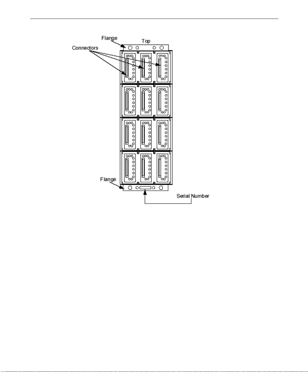
2. Turn the chassis upright to determine its proper vertical orientation. To determine
which end is the top, you can do the following:
−
Look inside the drive bays and note the docking connector for each drive. When the
chassis is right side up, these docking connectors are on the left side of each drive
bay, as shown in the following figure.
−
When the chassis is in the correct tower position, you can read the labels inside the
back of the chassis (where the power supplies, I/O module, and so on go).
−
The serial number on the front of the chassis (where the drives are inserted) is right
side up.
Page 4
2
Unpacking the Tower Kit Components
After you have determined which end is the top of the chassis, carefully unpack the tower kit
components.
To unpack the Fibre Channel tower kit components:
1. Open the box containing the Fibre Channel tower kit components.
2. Carefully slide out the tower cover, which is protected by a layer of protective wrap.
CAUTION All of the tower kit components are contained within the tower kit cover. To ensure that you
do not scratch the surface of the tower cover, leave the protective wrap on until you are ready
to install the cover.
3. The tower foot is held inside the cover with two pieces of Styrofoam. Hold the foot
securely, and remove one of the Styrofoam pieces. Then remove the other piece of
Styrofoam and take the plastic wrap off of the foot.
Page 5

CAUTION It is best to remove one piece of Styrofoam at a time, while holding the foot securely. This
portion of the tower kit is quite heavy, and could warp the tower cover if both pieces of foam
are removed at the same time and the foot slips.
4. Remove the front and rear brackets and set them aside. These are both black; the front
bracket is L-shaped and has a handle; the rear bracket is flat.
5. Remove the package containing the mounting screws and washers. This package also
contains a document titled “SS-1200 Tower Cover Kit Assembly Instructions,” which
has pictures you may find helpful while you are assembling the tower.
Assembling the Fibre Channel Tower Components
In a previous section, “Unpacking and Orienting the Fibre Channel Chassis,” you
determined which end of the chassis was the top side. If you have moved the chassis around,
make sure you still know which end is the top. The first component you will install is the
tower foot.
To assemble the Fibre Channel tower components:
1. Invert the chassis so that it is upside down.
2. Place the foot on the chassis, making sure that the flange on the front of the chassis fits
into the slot on the foot.
3
3. Use two M6 pan head screws and washers to attach the front of the foot to the bottom
front of the chassis (the pan head screws and their washers are the larger of the two
types of screws and washers provided in the tower kit).
NOTE The heads of the screws will face the back of the chassis.
4. Use two M5 countersunk screws and compression (crinkle) washers to attach the rear of
the foot to the rear of the chassis.
NOTE Because you will be inserting components into the chassis bays, you must insert the
countersunk screws and washers from inside the chassis. Also, you must ensure that the
screws are completely countersunk so that the components you install later will fit.
NOTE You may need a short screwdriver to install the screws from inside the chassis.
5. Turn the chassis upright on its foot. If you are working on a table or counter, make sure
you secure the chassis so that it doesn’t roll off of your work surface.
6. Using two M6 pan head screws and washers, attach the front bracket (the one that has a
handle) to the flange on the front of the chassis, aligning the holes in the bracket with
the inside holes on the flange. Again, the tops of the screws should face the rear of the
chassis.
7. Using two M5 countersunk screws and compression washers, attach the rear bracket (the
one that is L-shaped) to the top rear of the chassis.
Page 6

4
NOTE Proper placement of the cover depends on the brackets, so do not tighten the back bracket
fully in case you need to adjust it to make the cover fit.
8. Place the cover over the chassis. There are two slots, or notches, at the bottom of each
side of the tower cover front; these fit around the flange on the bottom front of the
chassis. Also, there is a cutout on the inside of the cover at the front and the back.
Make sure that the front and rear brackets fit inside these cutouts.
NOTE At this point, you may need to adjust the rear bracket to ensure that the cover fits properly.
9. Finish tightening the rear bracket screws you inserted in step 7 so that they are fully
countersunk.
10. Turn the unit upside down again, and use six M5 countersunk screws to secure the cover
to the unit.
11. Turn the unit right side up again.
Installing the Fibre Channel Storage System Components
Now that you have installed the tower foot and cover, you can install all of the components
in the Fibre Channel chassis. The SS-1200-FCAL Rack Installation and User Guide
describes each of the components of the storage system in detail. Installation of these
components is described for a rack-mount system; for example, the slots are referred to in
terms of left to right instead of top to bottom as in a tower configuration. The following
illustration shows the unit in the tower position with the slots labeled accordingly.
Page 7

5
Installing the Power Supplies, Operator Panel, and Input/Output Module
The following instructions show you how to install the components that go in the rear of the
Fibre Channel chassis.
WARNING Make sure that you wear the anti-static wrist strap included with the Tower Kit
components to avoid damaging the power supplies, operator panel, or I/O module.
See the
SS-1200-FCAL Rack Installation and User Guide
for more information.
To install the storage system components:
1. Remove the protective covering from each of the storage system components.
2. Check the power supplies and verify that the voltage switch is set to the correct voltage
(either 115V or 220V) for your country.
3. Turn the storage system around so that you are looking at the back of the unit (see the
previous illustration).
4. Remove the alignment screws and washers located above each side of slots 4 and 1 (see
the previous illustration). These ensure the correct orientation and secure placement of
the power supplies you will install; set these screws and washers aside for now because
you cannot install the power supplies while these screws are in place.
Page 8

6
NOTE Alignment screws are located in the upper left corner of each power supply bay, and in the
upper left corner of the slot 2. You only need to remove the alignment screws above each
power supply bay at this time.
CAUTION Be very careful with the power supplies, as they are heavy and the connecting pins can be
easily bent.
5. Install the first power supply (CPWS17900) in slot four; hold down the black tab to
make sure the component clicks into place.
CAUTION Make sure the label on the power supply faces the left of the chassis rear, or the power
supply will break when you install it. This is the same label that would be on the top of the
power supply in a rack-mount unit.
6. Using the same method described in the previous step, install the second power supply
(CPWS179) into slot 1.
7. Reinsert the two alignment screws and washers that you removed in step 2.
8. Remove the key that is taped to the operator panel (CINFE48), and install the panel in
the column 1 of slot 3, making sure that the “This Side Up” label on the operator panel
faces the left of the chassis rear; this label would be on the top in a rack-mount unit. Set
the key aside for now.
9. Insert the I/O module (CINFE49) in the middle column of slot 3. Again, make sure that
the “This Side Up” label faces the left of the chassis rear.
10. Place the smaller blanking plate (CGEN575) over the last column (3) in slot 3.
11. Remove the alignment screws and washers above slot 2, and place the final blanking
plate (CGEN574) over slot 2.
Populating the Fibre Channel Storage System Drive Bays
The following instructions show you how to install all of the drives in the proper order.
There are eight drives (CDSK238) and four dummy carriers (CGEN576) in a typical setup.
To open the drive front, you will push the indentation on the plastic cover. This indentation
should be on the top of each drive.
To install the Fibre Channel storage system drives:
1. Turn the storage system around so that you are looking at the front of the unit (refer to
the illustration in “Unpacking and Orienting the Fibre Channel Chassis” if necessary).
2. Press the indentation on a drive to open its door, and install this first drive in the bottom
right column of slot 4. Push the drive all the way in until the face of the drive is flush
with the trim on the tower cover, then press the indentation until it clicks shut. Again,
the indentation on the drive should be on the top.
3. Continue to install the remaining drives in the same fashion, working your way to the
top of the right column, then starting over at the bottom (slot 4) of the middle column.
Page 9

4. If you are only installing eight drives, place the dummy carriers (CGEN576) into the
remaining drive bays in the left column. These install the same way as the regular
drives and will look the same once installed, with the exception of the serial number
label (the dummy carriers do not have serial number labels). Otherwise, continue
installing the drives as described in steps 2 and 3.
NOTE Use a torx driver (CTOL805) to lock a drive. Insert the torx driver into the red, star-shaped
hole on the drive face. Turn the driver counterclockwise until you see a red tab appear in the
drive face; this indicates that the drive is locked and cannot be opened accidentally. See the
SS-1200-FCAL Rack Installation and User Guide
locks.
for more information on these anti-tamper
Setting Up the Fibre Channel Storage System
Once you have installed all of the storage system components, you are ready to hook it up to
a system and a power outlet and start creating. There are some things the system must have;
if you purchased the StudioZ GT1 workstation, it will have all of the requirements necessary
for the Fibre Channel storage system.
7
NOTE See the
StudioZ GT for SOFTIMAGE|DS System Guide
for information on this workstation.
Workstation Requirements
StudioZ GT1 base unit
Q-Logic adapter card (CINFE50)
Q-Logic driver software
Microsoft Windows NT 4.0
To connect the Fibre Channel storage system to your workstation:
1. Make sure that your workstation is properly shut down and powered off.
2. Connect the HSSDC end of the Fibre Channel cable (MCBL337) to the Fibre Channel
port on the Q-Logic adapter card in the StudioZ GT1 base and tighten the thumb screws.
3. Connect the DB9 end of the Fibre Channel cable to the FC-AL Tx/Rx port on the Fibre
Channel I/O module (column 2 of slot 3) and tighten the thumb screws.
4. Insert the key into the operator panel and turn it to the Service position (this is the key
that was taped to the operator panel module before you installed the module).
5. Connect the two female ends of the bifurcated power cord to both power supplies, then
plug the male end of the bifurcated power cord into the female end of the power cord.
Plug this into your power source (preferably the same power source that your StudioZ
GT1 workstation uses).
NOTE The part number for the power cord depends on the country where the workstation will be
used. Make sure you obtain the proper power cord for your region.
Page 10

8
WARNING The bifurcated power cord provides a single-source power connection. For safety
precautions, this power cord should always be used. The bifurcated power cord is the
same for all countries.
6. Power up your StudioZ GT1 workstation, and turn the key in the Fibre Channel I/O
module from Service to Run to power up the Fibre Channel storage system. See SS-
1200-FCAL Rack Installation and User Guide for more information on the I/O module.
NOTE The spinup light on each drive is a steady green when the Fibre Channel has powered up
properly. If you see an amber spinup light on any drive, make sure that the Fibre Channel
cable (MCBL337) is securely connected.
NOTE The initialization light on the Fibre Channel storage system is amber until Windows NT
initializes the storage system, whereupon this light turns green.
Installing Additional Fibre Channel Storage Systems
You can add up to two additional Fibre Channel Storage systems to the system discussed
above. Each of these systems is delivered with eight drives, and you can purchase four
additional drives for each storage system.
To add an additional Fibre Channel storage system:
1. Connect the HSSDC end of the Fibre Channel cable (MCBL337) to the Fibre Channel
port on the Q-Logic adapter card in the system and tighten the thumbscrews.
2. Connect the other end of the Fibre Channel cable to the female DB9 end of the Y cable
(MCBL384) and tighten the thumbscrews.
NOTE The side of the Y cable with two legs has one short leg and one long leg—both are male DB9
connectors.
3. Attach the short leg of the Y cable to the Tx/Rx port on the I/O module of the first Fibre
Channel chassis.
4. Attach the long leg of the Y cable to the Tx port on the I/O module in the second Fibre
Channel chassis.
5. Connect one end of a one-meter DB9-to-DB9 Fibre Channel cable (MCBL336) to the Tx
port on the first chassis; then connect the other end of the cable to the Tx/Rx port on the
second chassis.
To add a third Fibre Channel storage system:
1. Obtain an additional one-meter DB9-to-DB9 Fibre Channel cable (MCBL336A0).
2. Repeat steps 1 through 3 of the previous set of instructions.
3. Connect the long leg of the Y cable to the Tx port of the I/O module on the third Fibre
Channel chassis.
Page 11

4. Using the DB9-to-DB9 cable (MCBL336), connect the Tx port on the first chassis to the
Tx/Rx port on the second chassis.
5. Using the additional DB9-to-DB9 cable (MCBL336), connect the Tx port on the second
chassis to the Tx/Rx port on the third chassis.
NOTE Make sure that you tighten all of the cable thumbscrews.
6. Power up your StudioZ GT1 workstation, and turn the keys in each Fibre Channel I/O
module from Service to Run to power up the Fibre Channel storage systems. See SS-
1200-FCAL Rack Installation and User Guide for more information on the I/O module.
NOTE A steady green light appears on each drive when the Fibre Channel storage systems have
powered up properly. If you see an amber light on any drive, make sure that the Fibre
Channel cables (MCBL337) are securely connected.
9
 Loading...