

Intergraph TD-x10, InterServe x05 Series, TDZ-x10, TD-310, TD-410 System Reference Manual
...Page 1

TD/TDZ-x10, InterServe x05 Series
System Reference
September 1997
DHA018650
Page 2

Warranties and Liabilities
The information and the software discussed in this document are subject to change without notice and should not be
considered commitments by Intergraph Corporation. Intergraph Corporation assumes no responsibility for any errors
in this document.
The software discussed in this document is furnished under a license and may be used or copied only in accordance
with the terms of the license. No responsibility is assumed by Intergraph for the use or reliability of software on
equipment that is not supplied by Intergraph or its affiliated companies.
All warranties given by Intergraph Corporation about equipment or software are set forth in your purchase contract,
and nothing stated in, or implied by, this document or its contents shall be considered or deemed a modification or
amendment of such warranties.
Copyright
1997, Intergraph Corporation including this documentation, and any software and its file formats and audio-visual
displays described herein; all rights reserved; may only be used pursuant to the applicable software license
agreement; contains confidential and proprietary information of Intergraph and/or other third parties which is
protected by copyright, trade secret and trademark law and may not be provided or otherwise made available without
prior written authorization.
Restricted Rights Legend
Use, duplication, or disclosure by the United States Government is subject to restrictions as set forth in subdivision
(c)(1)(ii) of the rights in technical data and computer software clause at DFARS 252.227-7013.
Unpublished rights reserved under the copyright laws of the United States.
Intergraph Corporation, Huntsville AL 35894-0001
Trademarks
Intergraph
and the Intergraph logo are registered trademarks of Intergraph Corporation. TD, TDZ,
InterServe, and RealiZm are trademarks of Intergraph Corporation.
Microsoft
and Windows are registered trademarks of Microsoft Corporation. Windows NT is a trademark of
Microsoft Corporation.
Other brands and product names are trademarks of their respective owners.
Page 3

FCC Statement
This equipment has been tested and found to comply with the limits for a Class A digital device, pursuant to part 15
of the FCC Rules. These limits are designed to provide reasonable protection against harmful interference when the
equipment is operated in a commercial environment. This equipment generates, uses, and can radiate radio
frequency energy. If the equipment is not installed and used in accordance with the instruction manual, it may cause
harmful interference to radio communications.
Operation of this equipment in a residential area is likely to cause harmful interference in which case the user will be
required to correct the interference at his own expense.
CDC Statement
This digital apparatus does not exceed the Class A limits for radio noise emissions from digital apparatus set out in
the Radio Interference Regulations of the Canadian Department of Communications.
Warnings
Changes or modifications made to the system that are not approved by the party responsible for compliance could
void the user’s authority to operate the equipment.
To reduce the risk of electrical shock, do not attempt to open the equipment unless instructed. Do not use a tool for
purposes other than instructed.
There is a danger of explosion if the battery is incorrectly replaced. Replace the battery only with the same or
equivalent type as recommended by the manufacturer. Dispose of used batteries according to the manufacturer’s
instructions.
There are no user serviceable parts in the power supply. Refer all servicing of the power supply to qualified service
personnel.
Cautions
THIS PRODUCT CONFORMS TO THE APPLICABLE REQUIREMENTS OF 21 CFR SUBCHAPTER J AT
DATE OF MANUFACTURE.
Read all operating instructions before using the equipment. Keep these instructions for future reference. Follow all
warnings on the equipment or in the operating instructions.
Page 4

Page 5

Contents
Introduction.....................................................................................................................ix
Restrictions........................................................................................................................ ix
Conventions.......................................................................................................................ix
Additional System Information......................................................................................... ix
Operating System Information........................................................................................... x
1 Accessing the System..................................................................................................... 1
Desktop System..................................................................................................................1
Opening the Base Unit......................................................................................... 1
Avoiding Electrostatic Discharge......................................................................... 2
Closing the Base Unit .......................................................................................... 3
Deskside Base Unit ............................................................................................................ 4
Opening the Base Unit......................................................................................... 4
Avoiding Electrostatic Discharge......................................................................... 7
Closing the Base Unit .......................................................................................... 8
2 Servicing the Desktop System....................................................................................... 9
Floppy Disk Drive or Combo Drive................................................................................... 9
CD-ROM Drive................................................................................................................ 10
System Hard Disk Drive................................................................................................... 11
SCSI Termination Card.................................................................................................... 12
Riser Card ........................................................................................................................ 13
System Board................................................................................................................... 14
CMOS/Clock Battery....................................................................................................... 16
Power Supply................................................................................................................... 17
v
3 Servicing the Deskside System.................................................................................... 19
Internal SCSI Drives ........................................................................................................ 19
Floppy Disk Drive or Combo Drive................................................................................. 21
RAID Section................................................................................................................... 22
System Hard Disk Drive................................................................................................... 23
Riser Card ........................................................................................................................ 24
Processor Module............................................................................................................. 26
P6 Bus Termination Card................................................................................................. 26
System Board................................................................................................................... 27
System Hard Disk Drive Fan............................................................................................ 29
Option Board Fans ........................................................................................................... 30
CMOS/Clock Battery....................................................................................................... 31
Power Supply................................................................................................................... 32
Power Distribution Board................................................................................................. 33
4 Upgrading the System................................................................................................. 35
Adding Memory............................................................................................................... 35
Adding Internal SCSI Devices ......................................................................................... 37
Adding External SCSI Devices........................................................................................ 38
Cable Length Requirements............................................................................... 38
Connecting the Device....................................................................................... 39
Disabling SCSI Sync Negotiation...................................................................... 40
Page 6

vi
Adding Option Boards ..................................................................................................... 40
Primary PCI Slots .............................................................................................. 41
PCI Option Boards............................................................................................. 41
ISA Option Boards............................................................................................. 42
Using the System Configuration Utility............................................................................ 43
ISA Boards with a Configuration File................................................................ 43
ISA Boards without a Configuration File........................................................... 44
5 System Board............................................................................................................... 47
Components and Chipsets................................................................................................ 48
Lithium Battery (CMOS/Clock Battery)............................................................ 49
Graphics Chipset................................................................................................ 49
SCSI Controller.................................................................................................. 50
I/O Controller..................................................................................................... 50
Processor Components....................................................................................... 51
Memory Components......................................................................................... 52
BIOS Components ............................................................................................. 53
Sound Controller................................................................................................ 54
Cable Connectors ............................................................................................................. 55
Floppy Pinout..................................................................................................... 56
Audio Pinout...................................................................................................... 56
ISA Bus J32 Pinout............................................................................................ 56
ISA Bus J33 Pinout............................................................................................ 57
Address Configuration ..................................................................................................... 57
DMA Channels .................................................................................................. 57
Input/Output Addresses...................................................................................... 57
Memory Address Map ....................................................................................... 58
PCI to ISA Bus Interrupt Mapping .................................................................... 58
PCI Bus Configuration Space ............................................................................ 59
ISA Bus IRQ Assignments................................................................................. 59
External Ports................................................................................................................... 60
MIDI Pinout....................................................................................................... 60
Ethernet Pinout................................................................................................... 60
Serial (COM) Pinout.......................................................................................... 61
Mouse and Keyboard Pinout.............................................................................. 61
Video Pinout ...................................................................................................... 61
SCSI Pinout........................................................................................................ 62
Parallel Pinout....................................................................................................62
6 Riser Cards.................................................................................................................. 63
Desktop Riser Card (MSMT345)..................................................................................... 63
Expansion Slots.................................................................................................. 63
Graphics Card Slot Assignments........................................................................ 63
Deskside Riser Card (MSMT280, MSMT463) ................................................................ 64
Expansion Slots.................................................................................................. 64
SCSI Controller and Connector ......................................................................... 64
Graphics Card Slot Assignments........................................................................ 65
7 Power Supplies, Power Distribution Board, and Fans............................................. 67
Deskside Power Supply (MPWS131) .............................................................................. 67
DC Output Specifications .................................................................................. 67
Cable Connectors............................................................................................... 68
P1 Pinout............................................................................................................ 68
P2 - P8 Pinout .................................................................................................... 68
P9 Pinout............................................................................................................ 69
Page 7

Power Distribution Board (MPCBD13) ........................................................................... 69
Cable Connectors............................................................................................... 69
Deskside Fans...................................................................................................................71
Option Board Fans (MCBLZ520 and MCBLY690) .......................................... 71
RAID Fan (CFAN111)....................................................................................... 71
System Disk Fan (MCBL172A)......................................................................... 71
Desktop Power Supplies................................................................................................... 71
300 W DC Output Specifications....................................................................... 71
200 W DC Output Specifications....................................................................... 72
Cable Connectors............................................................................................... 73
P1 Pinout............................................................................................................ 73
P2 Pinout............................................................................................................ 73
P3 Pinout............................................................................................................ 73
P4 Pinout............................................................................................................ 74
P5 Pinout............................................................................................................ 74
P6, P7, P8 Pinout ............................................................................................... 74
P9 Pinout............................................................................................................ 74
Desktop Fans....................................................................................................................74
8 Peripherals...................................................................................................................75
RAID Section................................................................................................................... 75
CD-ROM Drive................................................................................................................ 77
Disk Drives....................................................................................................................... 77
CDSK111 1 GB ................................................................................................. 78
CDSK094 2 GB ................................................................................................. 78
CDSK098 4 GB ................................................................................................. 79
CDSK123 4 GB ................................................................................................. 79
Floppy Disk Drive............................................................................................................ 80
Combo Drive....................................................................................................................80
vii
A Additional System Information................................................................................. 83
Cleaning the System.........................................................................................................83
Specifications................................................................................................................... 83
Product Model Number.................................................................................................... 84
Index................................................................................................................................85
Page 8

viii
Page 9

Introduction
TD/TDZ-x10, InterServe x05 System Reference provides the information necessary for servicing the
following systems:
u
Workstations (desktop and deskside) -- TD-310, TD-410, TDZ-310, TDZ-410, TDZ-610
u
Servers (desktop and deskside) -- InterServe 305, InterServe 605, and Interserve 605UW
Restrictions
In the servicing instructions, heed all warnings and cautions. Some precedures may only be performed
by trained Intergraph Field Service personnel. Personal injury and damage to equipment can occur if
documented procedures are not followed.
CAUTION Use an antistatic wrist strap for all servicing and upgrade procedures to avoid the possibility of
electrostatic discharge.
ix
Conventions
Bold
Italic Variable values that you supply, or cross-references.
Monospace
SMALL CAPS Key names on the keyboard, such as D, ALT or F3. Names of files and
CTRL+D Press a key while simultaneously pressing another key; for example, press CTRL
Commands, words, or characters that you key in literally.
Output displayed on the screen.
directories. You can type filenames and directory names in the dialog boxes or
the command line in lowercase unless directed otherwise.
and D simultaneously.
Additional System Information
A System Setup is shipped with each system, and provides detailed information about:
u
Setting up the system.
u
Configuring the operating system and associated system software.
u
Using the system.
u
Using the AMIBIOS Setup program.
u
Installing system software.
A System Introduction is delivered with the system, and provides information about:
u
Intergraph Support
u
System hardware features
u
Available hardware options
Page 10

x
Operating System Information
For more detailed information on the Windows NT Server 4.0 operating system, refer to the printed
and online Windows NT documentation from Microsoft:
u
For basic information on using and installing Windows NT Server 4.0, refer to Start Here,
delivered in the Windows NT Server software package.
u
For detailed information on using Windows NT Server 4.0, refer to Windows NT Server Help.
u
Additional online Windows NT Server 4.0 documentation is delivered on CD-ROM with the
operating system. You can purchase printed copies of these documents from Intergraph.
Refer to the Late-Breaking News shipped with your system for important hardware, software, and
documentation information not covered in this document.
Page 11
1 Accessing the System
This chapter describes how to access the desktop and deskside systems.
u
Opening the base unit
u
Avoiding electrostatic discharge
u
Closing the unit
After opening the system, you need the following tools to upgrade or replace system parts:
u
Quarter-inch nutdriver
u
No. 1 Phillips screwdriver
u
No. 2 Phillips screwdriver
u
Three-sixteenth-inch nutdriver
u
Five-sixteenth-inch or 8 mm nutdriver
u
Small single-slot screwdriver
1
NOTE The parts inside the base unit are designed to fit within very tight tolerances. Some force is required to
remove or insert parts. However, if you cannot remove or install a part properly, ensure there are no
obstructions hindering the part.
Desktop System
The desktop system features a tool-less entry chassis, for quick access to internal parts.
Opening the Base Unit
WARNING Before opening the base unit, turn the system power off. Use caution when removing the top
cover to avoid injury.
To open the base unit of a desktop system:
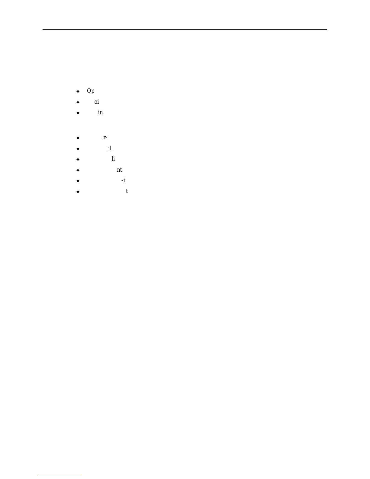
1. Pull the plunger out and rotate it to lock it in the open position. Refer to the following figure:
Page 12
2
ISA I/O Panel Plunger
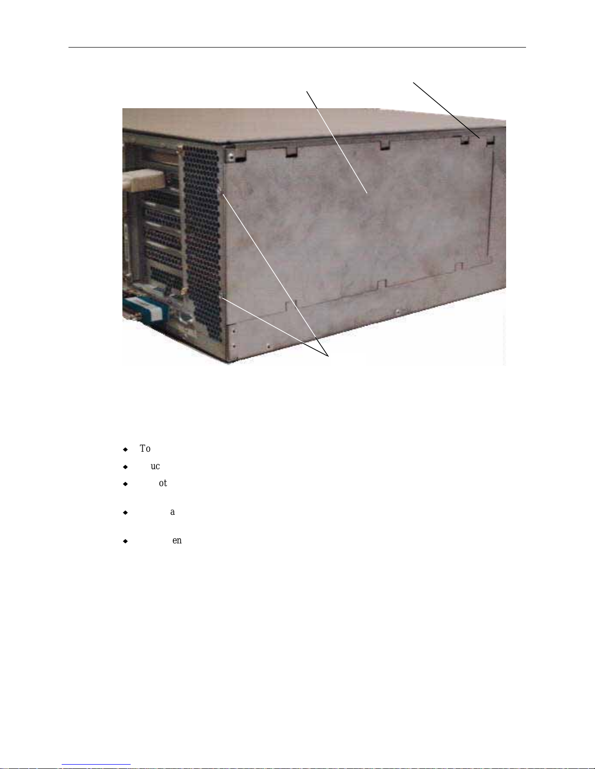
2. Lift up the top cover above the ISA I/O panel and pull it up and back.
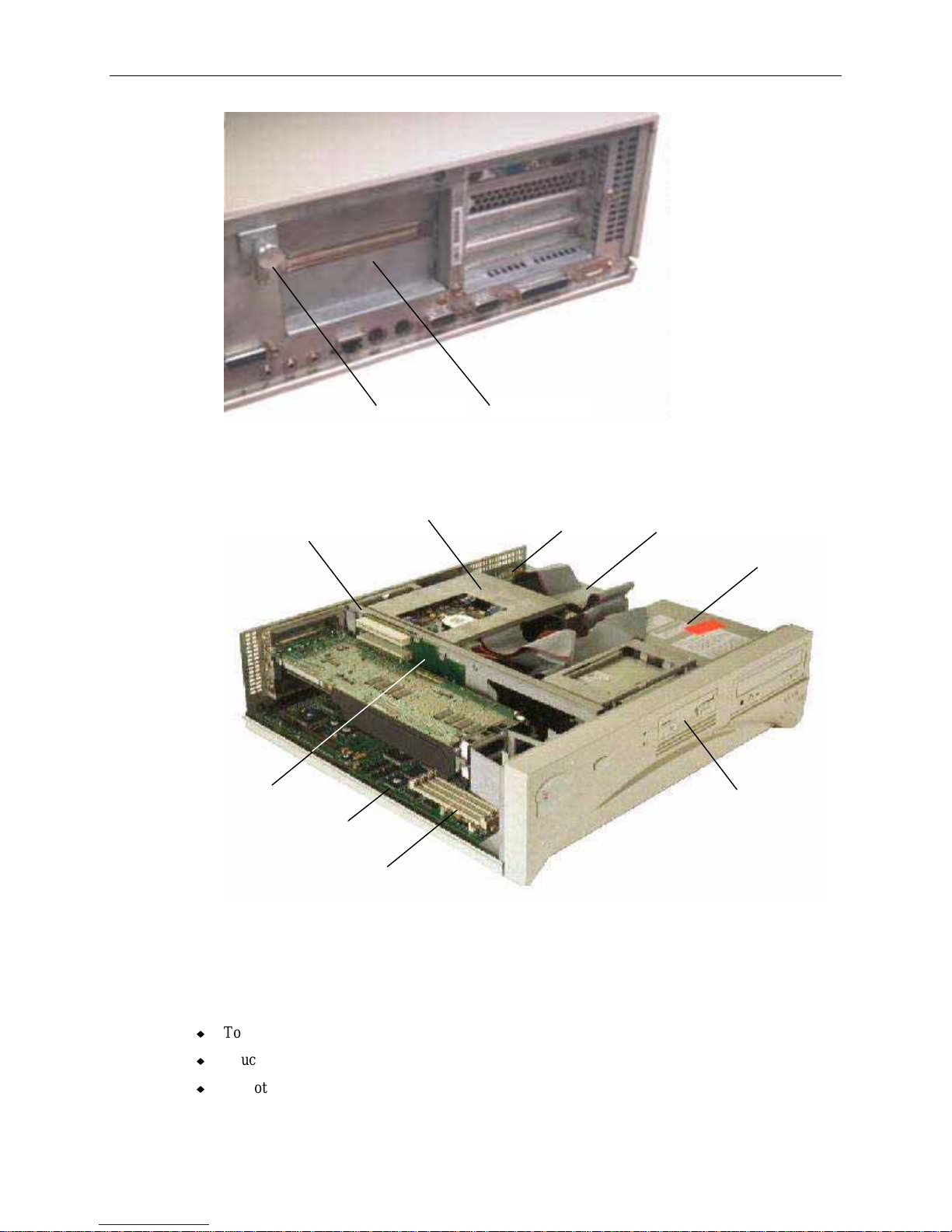
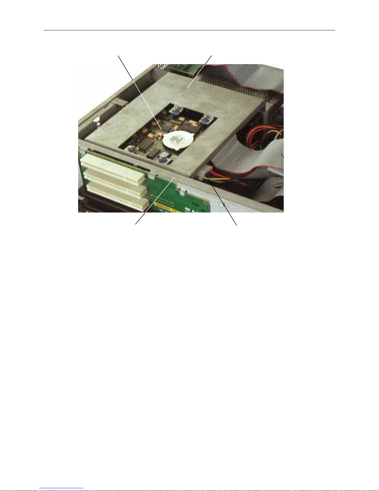
3. Set the top cover aside. The following figure shows inside the base unit.
System Hard Disk
Peripheral
Brace
Riser Card
Drive Bracket
System
Board
Memory Sockets
Avoiding Electrostatic Discharge
SCSI Terminator
Card
Power Supply
CD-ROM
Drive
Floppy
Disk Drive
Some of the sensitive components inside the base unit can be damaged by static electricity. To
minimize this possibility, take the following precautions when working with the internal components of
the system.
u
To maintain ground, do not unplug the power cord from the base unit, AC outlet, or UPS.
u
Touch the bare metal of the base unit to discharge any accumulated electrostatic charge.
u
Do not service the system on surfaces known to have high electrostatic buildup, such as rugs and
carpets. Work on a static-safe surface instead.
Page 13

u
Handle all printed circuit boards as little as possible and by the edges only. Leave new parts in
their protective packaging until you install them.
u
After opening the base unit, attach a disposable or reusable antistatic wrist strap as described
following.
NOTE There is no increased risk of electrical shock when using an antistatic wrist strap. If the wrist strap
does not snugly contact bare skin, static protection will not be effective.
To attach a disposable antistatic wrist strap:
1. Remove the wrist strap from the envelope.
2. Unfold the wrist strap and wrap the exposed adhesive side firmly around your bare wrist.
3. Peel the liner from the wrist strap copper foil. Attach the adhesive side of the copper foil to a bare
flat metal surface (electrical ground) inside the base unit.
NOTE After using a disposable wrist strap once, you cannot use it again.
To attach a reusable antistatic wrist strap:
1. Attach the wrist strap to the ground loop above the ISA slots on the back of the base unit.
2. Slip the elastic end of the wrist strap snugly around your bare wrist.
NOTE The metal conductor bead in the elastic must contact bare skin.
3
Closing the Base Unit
To close the base unit:
1. Remove the antistatic wrist strap from the ground loop inside the base unit.
2. Replace the top cover by aligning the tabs on the front of the top cover with the notches behind the
faceplate.
3. Lower the back of the top cover and slide it into place.
4. Turn the plunger to lock the top cover to the base unit.
Page 14

4
Deskside Base Unit
CAUTION The parts inside the base unit are designed to fit within very tight tolerances. Some force is required to
remove or insert parts. However, if you cannot remove or install a part properly, ensure there are no
obstructions hindering the part.
Opening the Base Unit
To open the base unit, you need to remove the top cover, side panels, and other parts listed depending
on the part you need to service or upgrade, as follows.
To Service
Internal SCSI drives Top cover, both side panels
Combo drive Top cover, both side panels
Internal RAID Section Top cover, both side panels
Riser card Top cover, left side panel, PCI access panel, riser card brace
Processor module Top cover, left side panel, PCI access panel
P6 bus termination card Top cover, left side panel, PCI access panel
System board Top cover, left side panel, PCI access panel, option board bracket
Power Supply Top cover
Power distribution board Top cover, left side panel
InterSite Server Monitor board Top cover, left side panel
Memory Top cover, left side panel, PCI access panel, PCI board guide
Option board fan assembly Top cover, left side panel, option board bracket
System Disk Fan Top cover
Auxiliary fan Top cover, power supply access panel
Lithium Battery Top cover, left side panel
To Upgrade
Processors Top cover, left side panel
Memory Top cover, left side panel, PCI access panel, PCI board guide
Internal SCSI drives Top cover, both side panels
External SCSI drives n/a
Option Boards Top cover, left side panel, PCI access panel
Remove
Remove
Page 15
To remove the top cover and side panels:
NOTE The left and right side panels are identified as if you are facing the front of the base unit.
1. Remove the footstands.
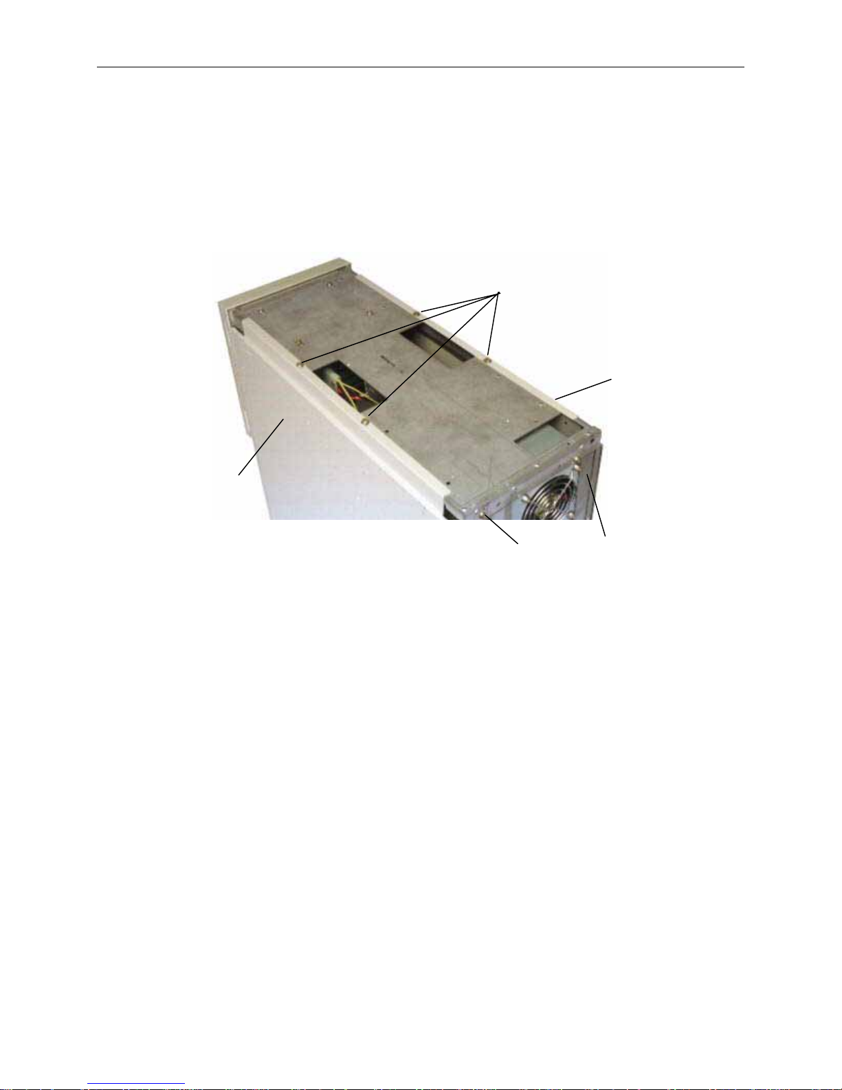
2. Remove the screw on the back cover. Pull the top cover back an inch and lift it off the base unit.
Refer to the following figure.
3. Remove the two screws on the left or right side panel. Then pull the panel up and out to remove it.
Refer to the following figure.
Screws
Left Side
Panel
5
Right Si de
Panel
Screw
4. Set the cover and panels aside. The following figure shows inside the base unit.
Back Cover
Page 16
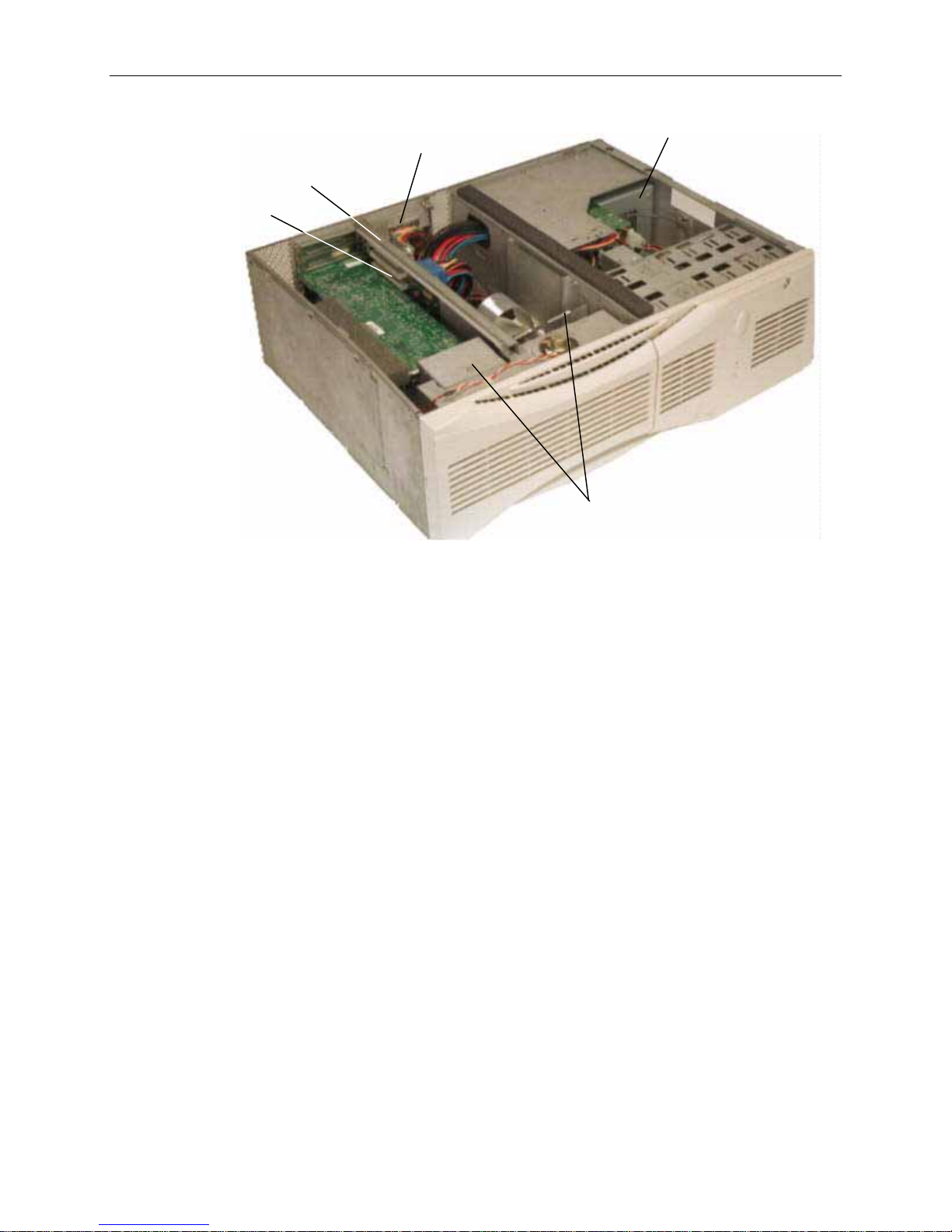
6
Peripheral
Brace
Riser Card
To remove the PCI access panel:
External SCSI
Connector
Power Supply
Option Card Guides
1. Power off the base unit and remove the top cover and side panel. Lay the base unit on the right
side.
2. Remove the two screws at the bottom of the unit and the screw behind the PCI access panel as
shown in the following figure.
3. Slide the PCI access panel to the back of the base unit and remove it.
Page 17
7
PCI Access
Panel
Screw
(Behind Panel)
Screws
Avoiding Electrostatic Discharge
Some of the sensitive components inside the base unit can be damaged by static electricity. To
minimize this possibility, take the following precautions when working with the internal components of
the system.
u
To maintain ground, do not unplug the power cord from the base unit, AC outlet, or UPS.
u
Touch the bare metal of the base unit to discharge any accumulated electrostatic charge.
u
Do not service the system on surfaces known to have high electrostatic buildup, such as rugs and
carpets. Work on a static-safe surface instead.
u
Handle all printed circuit boards as little as possible and by the edges only. Leave new parts in
their protective packaging until you install them.
u
After opening the base unit, attach a disposable or reusable antistatic wrist strap as described in the
next section.
NOTE There is no increased risk of electrical shock when using an antistatic wrist strap. If the wrist strap
does not snugly contact bare skin, static protection will not be effective.
To attach a disposable antistatic wrist strap:
1. Remove the wrist strap from the envelope.
2. Unfold the wrist strap and wrap the exposed adhesive side firmly around your bare wrist.
3. Peel the liner from the wrist strap copper foil. Attach the adhesive side of the copper foil to a bare
flat metal surface (electrical ground) inside the base unit.
NOTE After using a disposable wrist strap once, you cannot use it again.
Page 18

8
To attach a reusable antistatic wrist strap:
1. Attach the wrist strap to the ground loop above the ISA slots on the back of the base unit.
2. Slip the elastic end of the wrist strap snugly around your bare wrist.
NOTE The metal conductor bead in the elastic must contact bare skin.
Closing the Base Unit
To close the base unit:
1. Remove the antistatic wrist strap from the ground loop inside the base unit.
2. Replace the PCI access panel if removed.
3. Set the base unit in the upright position.
4. Replace the left or right side panel if removed.
5. Replace the top cover. Ensure the top cover is completely installed so the safety interlock switch
engages. If the cover is not properly installed, the system will not start.
6. Replace the footstands.
CAUTION After servicing or upgrading the system, always replace all panels and covers. T he panels and covers
ensure the system maintains proper air flow, so internal components do not overheat. Overheated
components may fail prematurely and may be dangerous to touch. The panels and covers also ensure
electromagnetic interference (EMI) emissions are kept to levels below the standard requirements.
Page 19
2 Servicing the Desktop System
This chapter describes how to replace parts in the desktop system, including the following items:
u
Floppy disk drive or combo drive
u
CD-ROM drive
u
System hard disk drive
u
SCSI termination card
u
Riser card
u
System board
u
CMOS/Clock battery
u
Power supply
Before replacing any parts, open the base unit and take precautions against electrostatic discharge as
described in Chapter 1, “Accessing the System.” After replacing system parts, close the base unit as
described in Chapter 1.
9
CAUTION The parts inside the base unit are designed to fit within very tight tolerances. Some force is required to
remove or insert parts. However, if you cannot remove or install a part properly, ensure that there are
no obstructions hindering the part.
Floppy Disk Drive or Combo Drive
To replace the floppy disk drive or combo drive:
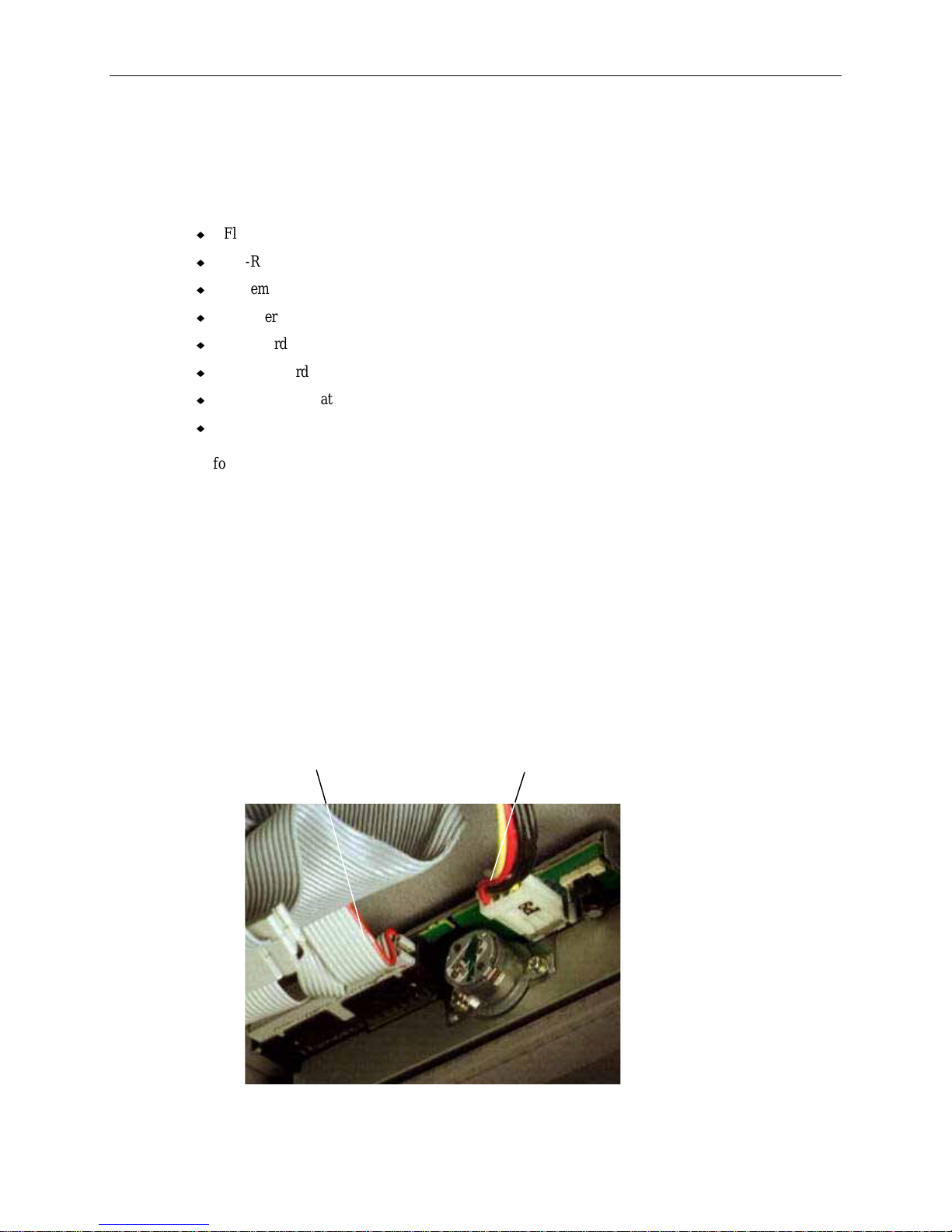
1. Disconnect the cables. The floppy drive cable on a combo drive is connected to the side of the
drive. Note the position of pin 1 (identified by the red stripe) on the floppy drive cable. Refer to
the following figure.
Data Cable
Connector
Power Cable
Connector
Page 20
10
2. Remove the screws holding the drive to each side of the chassis. Slide the drive and its support
bracket out of the base unit.
3. Remove the support bracket from the drive. Mount the replacement drive to the support bracket
using the screws removed previously.
4. Install the drive and its support bracket into the base unit.
5. Connect the cables to the drive. On a combo drive, connect the floppy drive cable to the connector
on the side of the device.
CD-ROM Drive
To replace the CD-ROM drive:
1. Remove the floppy disk drive or combo drive as described previously in step 2 of “Floppy Disk
Drive or Combo Drive,” leaving the cables attached.
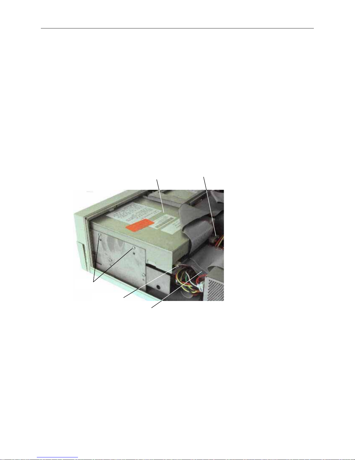
2. Disconnect the cables from the CD-ROM drive. Refer to the following figure.
CD-ROM
Drive
Power
Cable
Screws
Cable
Audio
SCSI Cable
3. Disconnect the audio cable from its system board connector.
4. Remove the screws holding the CD-ROM drive to each side of the chassis.
5. Slide the CD-ROM drive forward and out of the base unit.
6. Disable SCSI termination and set the SCSI ID. Refer to the vendor’s CD-ROM drive
documentation for instructions.
7. Insert the new CD-ROM drive through the front panel.
8. Secure the CD-ROM drive to the chassis using the screws removed previously.
9. Connect the SCSI cable and power cable to the CD-ROM drive. The SCSI cable is keyed to
ensure proper insertion, so that the red stripe (pin 1) is adjacent to the power connector.
10. If installing an Intergraph CD-ROM drive, the audio cable is already connected to the drive.
Connect the loose end of the audio cable to the system board connector.
Page 21
11. If installing a non-Intergraph CD-ROM drive, connect the audio cable delivered with the new CDROM drive to the connectors on the drive and the system board.
12. Replace the floppy disk drive or combo drive.
System Hard Disk Drive
The system hard disk drive is located between the power supply and the riser card.
To replace the system hard disk drive:
1. Disconnect the SCSI and power cables from the hard disk drive.
2. Remove the drive and its support bracket; then set the drive on a flat antistatic surface.
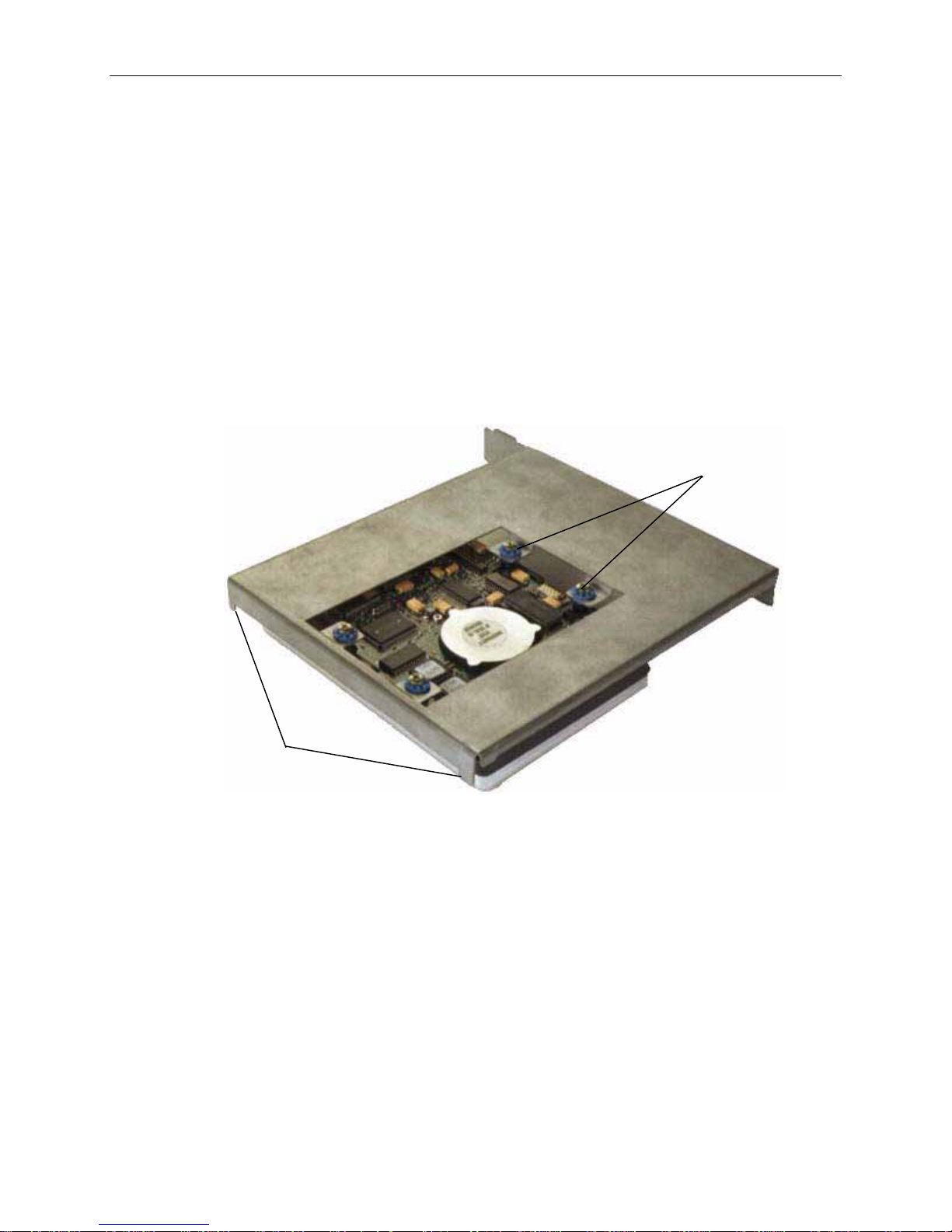
3. Remove the screws securing the hard disk drive to the bracket. Leave the grommets in the bracket.
Refer to the following figure.
11
Screws
Tabs
4. Disable SCSI termination and set the SCSI ID to the same SCSI ID as the previous hard disk drive.
Refer to the documentation delivered with the drive for instructions.
5. Secure the new drive to the support bracket using the screws removed previously.
6. Attach the cables to the new drive. The SCSI cable is keyed to ensure proper insertion, so that the
red stripe (pin 1) is adjacent to the power connector.
7. Install the drive and bracket into the base unit, inserting the tabs into the slots.
Page 22
12
System Hard
Disk Drive
Peripheral
Brace
Support Bracket
Power Cable
8. After closing the base unit and restarting the system, partition and format the system hard disk
drive as described in the operating system documentation.
SCSI Termination Card
The SCSI termination card terminates the internal SCSI cable chain. If external SCSI devices are
connected, the card disables termination and acts as a pass-through external SCSI connector.
To replace the SCSI termination card:
1. Disconnect the external SCSI cable from the external SCSI port.
2. Remove the screws securing the external SCSI port to the back panel.
3. Note how the SCSI termination card is attached. Slide the card out of the chassis and disconnect
the internal SCSI cable.
Page 23

Internal SCSI
Cable
13
External
SCSI Port
Screws
SCSI Termination Card
4. Connect the internal SCSI cable to the new termination card.
5. Insert the new card into the chassis and mount the external SCSI port to the back panel using the
screws removed previously.
6. Close the base unit and connect the external SCSI cable to the port.
Riser Card
To replace the desktop riser card:
1. Remove the floppy disk drive as described previously in step 2 of “Floppy Disk Drive or Combo
Drive” leaving the cables attached.
2. Remove the system hard disk drive as described previously in step 2 of “System Hard Disk Drive”
leaving the cables attached.
3. Remove all boards connected to the riser card. Note the position of each board installed in the ISA
slots. To remove the ISA boards in the ISA I/O panel, remove the I/O lock bracket (note
orientation) as shown in the following figure.
Page 24
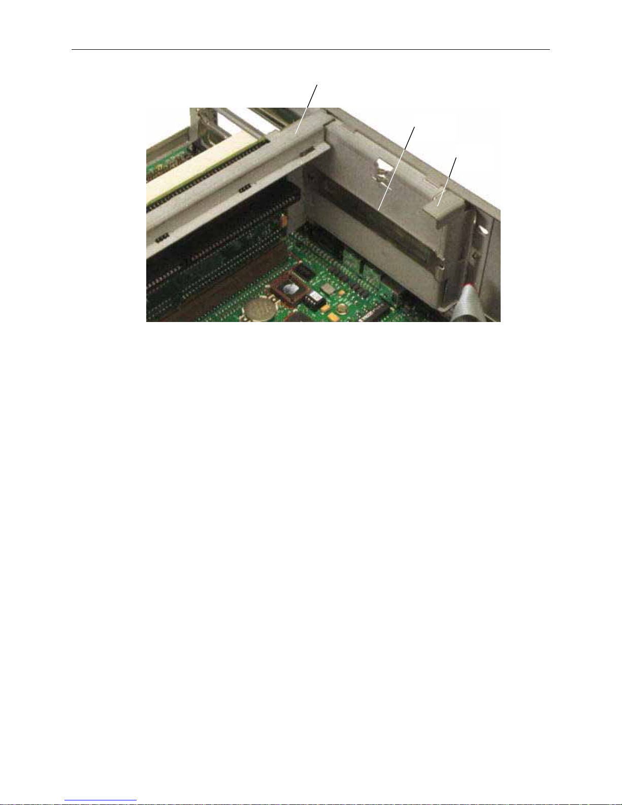
14
Peripheral
Brace
Blanking
Plate
I/O Lock
Bracket
4. Lift up and remove the peripheral brace as shown in the previous figure.
5. Disengage the riser card from the system board, and remove the card from the base unit.
6. Insert the new riser card into the system board slot, pushing firmly over the center of the PCI
connectors to ensure it seats completely.
CAUTION Do not rock the riser card back and forth; pins inside the connector may be damaged as a result.
Press firmly so the card connector slides evenly into the slot.
7. Replace the peripheral brace.
8. Replace the option boards connected to the riser card. Connect any external cables attached to the
boards. ISA boards must be installed in the same slots from which they were removed.
9. Replace the ISA I/O lock bracket.
10. Connect the SCSI and power cables to the riser card, if necessary.
11. Replace the system hard disk drive and the floppy disk drive.
System Board
CAUTION The system board is extremely sensitive to static electricity. To prevent serious damage to the system
board, wear the antistatic wrist strap while performing the following steps. Do not open the antistatic
bag containing the system board until instructed.
To remove the system board:
1. In a desktop system, remove the system hard disk drive as described previously in “System Hard
Disk Drive.”
2. In a desktop system, remove the floppy disk drive as described previously in “Floppy Disk Drive
or Combo Drive.”
3. Remove the riser card as described previously in “Replacing the Riser Card.”
Page 25
4. Note the orientation of the reset, disk activity LED, and power on LED cables; then disconnect the
LED cables from the system board.
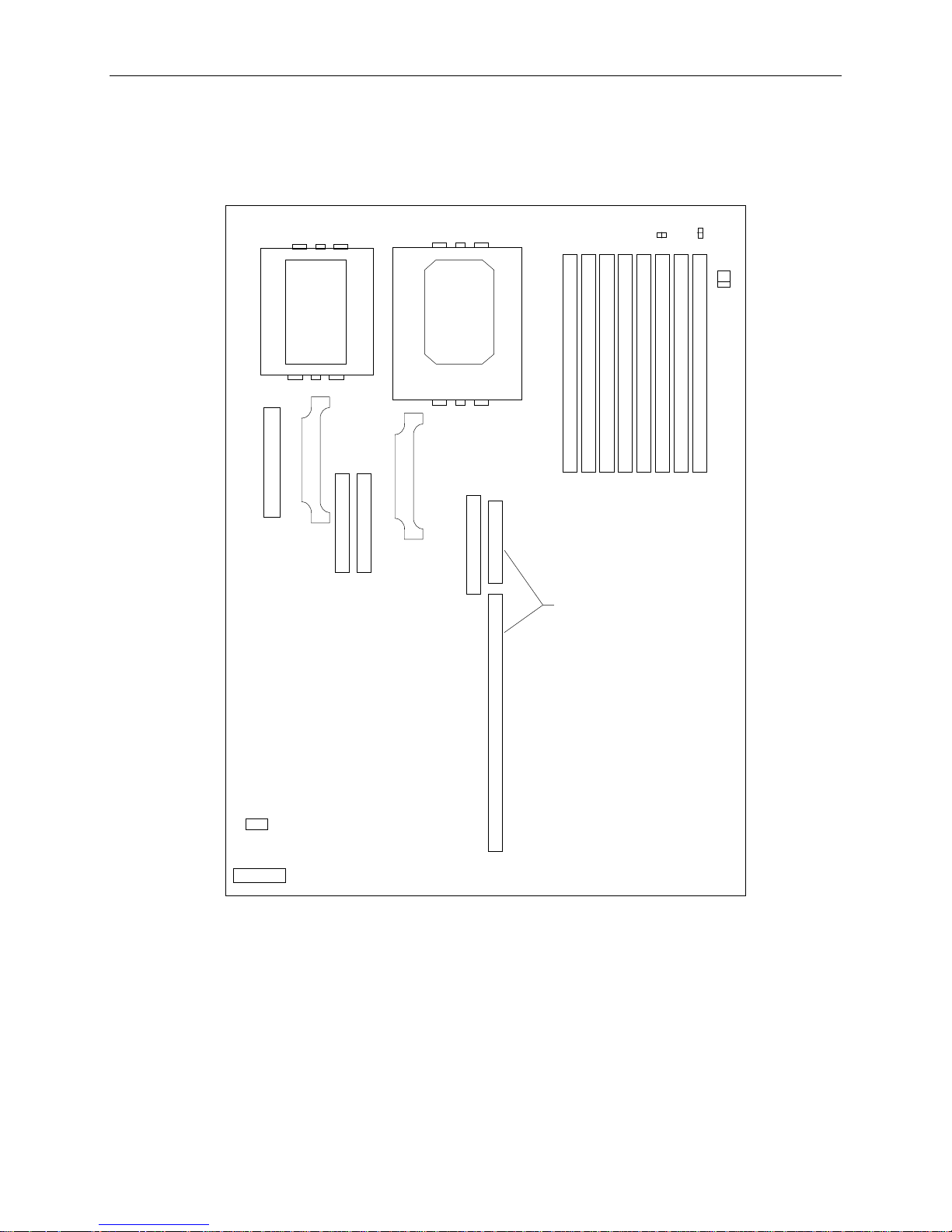
5. Disconnect all other cables from the system board. The following figure shows the cable
connector locations.
15
SCSI -
J43
CPU 0
ISA Bus -
J32
VRM 0
ISA Bus J33
CPU 1
VRM 1
Floppy -
J30
Memory Sockets
Riser Card
Connectors
J74
J71
J68
Audio - J22
MIDI - J17
6. Disconnect the cables from the external ports.
7. Remove the jackscrews from the video, parallel, and serial ports.
8. Remove the hex nuts from the audio jacks.
9. Remove the eight grounding screws from the system board.
10. Slide the system board to the front of the base unit.
11. Lift the board and remove it from the base unit. Set the board on a flat antistatic surface.
12. Remove the new system board from the antistatic bag and place it on a flat antistatic surface.
Page 26

16
13. Remove the SIMMs from the old system board and install them onto the new one in the same
configuration.
14. If a Windows RAM (WRAM) expansion module for G95 graphics is installed, remove the module
and install it onto the new system board.
To install a new system board:
The new system board should have the SIMMs and WRAM module (if required) installed before
placing it into the base unit.
1. Lower the new system board into the base unit. Ensure the standoff lines up with the hole in the
chassis. Slide the system board to the back of the base unit so the external ports fit into the back
panel.
2. Install the eight grounding screws.
3. Install the hex nuts onto the audio jacks.
4. Install the jackscrews onto the video, parallel, and serial ports.
5. Connect the MIDI (or game) and CD-ROM audio cables to the system board.
6. Connect the system power cables to the P1 through P5 connectors. The power cable connectors
are labeled with the corresponding system board connector.
7. Connect the LED and Reset cables to the system board.
NOTE The orange wire for the disk activity LED cable must connect to pin 1. The white wire for the power on
LED cable must also connect to pin 1. The orientation of the reset cable wires is not critical.
8. Install the riser card and the peripheral brace.
NOTE If installing ISA boards they must be placed in the same slots from which they were removed. Also
replace the I/O lock bracket for the ISA boards on side two of the riser card.
9. Install the floppy disk drive or combo drive; then connect the power cable and data cables to the
system board.
10. Install the system hard disk drive and connect the SCSI cable to the system board.
CMOS/Clock Battery
WARNING There is a danger of explosion if the battery is incorrectly replaced. Replace the battery with the
same or equivalent type only, as recommended by the manufacturer. Dispose of used batteries
according to the manufacturer’s instructions.
To replace the CMOS/clock battery:
1. Remove the system hard disk drive as described in step 2, “System Hard Disk Drive.” Leave the
cables attached. The battery is located on the system board at location B1. Refer to the following
figure.
Page 27
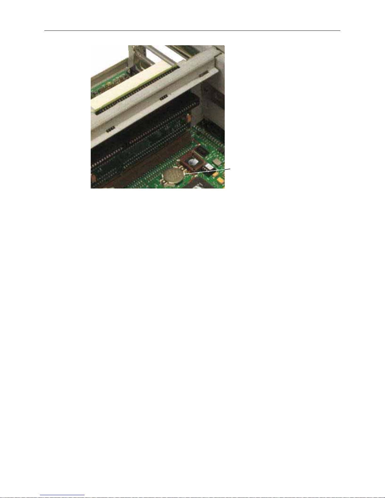
Battery
2. Carefully remove the discharged battery by grasping it firmly and lifting upward.
3. Install the new battery in the same orientation as the discharged battery.
17
4. Replace the system hard disk drive, inserting the bracket tabs into the slots on the peripheral brace.
Power Supply
CAUTION Purchase replacement power supplies from Intergraph to ensure proper specifications are met and to
guarantee safety.
WARNING Set the AC voltage switch on the back of the power supply to the correct voltage for your
location, or the power supply will be irreparably damaged when power is applied. If you do not
know the voltage range, call your local utilities company for assistance.
To replace the power supply:
1. Remove the AC power cord from the back of the base unit.
2. Remove the SCSI termination card as described previously in “SCSI Termination Card.” It is not
necessary to disconnect the card from the SCSI cable.
3. Remove the system disk drive as described in “System Hard Disk Drive.”
4. Disconnect the power cable from the floppy disk drive, CD-ROM drive, and hard disk drives.
5. Disconnect the system power cables from the P1 through P5 connectors on the system board. Take
note of the cable number (Px) attached to each connector on the system board.
Page 28

18
6. Open the clip that secures the bundle of power cables. Remove the audio cable from the power
cable bundle. The audio cable connects the CD-ROM drive to the system board.
7. Remove the screws securing the power supply to the back of the base unit.
8. Slide the power supply to the front and remove it from the base unit.
9. Remove the power switch cable and grounding wire from the base unit.
10. Set the AC voltage switch on the back of the new power supply to the correct voltage for your
location.
11. Slide the new power supply into place in the base unit. Mount the power supply using the screws
removed previously.
12. Mount the power switch cable and grounding wire to the base unit.
13. Replace the system hard disk drive.
14. Connect the system power cables to the P1 through P5 connectors on the system board.
15. Connect the remaining power cables to the system hard disk drive, CD-ROM drive, and floppy
drive.
16. Connect the audio cable to the system board and to the CD-ROM drive.
17. Secure the clip around the power cables and audio cable.
18. Replace the SCSI termination card.
19. Connect the AC power cord to the back of the base unit.
Page 29
3 Servicing the Deskside System
This chapter describes how replace parts in the deskside system, including the following devices:
u
Internal SCSI drives
u
Floppy disk drive or combo drive
u
RAID section
u
System hard disk drive
u
Auxiliary drives
u
Riser card
u
Processor module
u
P6 termination card
u
System board
u
System hard disk drive fan
u
Option board fans
19
u
CMOS/clock battery
u
Power supply
u
Power distribution board
Before replacing any parts, open the base unit and take precautions against electrostatic discharge as
described in Chapter 1, “Accessing the System.” After replacing system parts, close the base unit as
described in Chapter 1.
CAUTION The parts inside the base unit are designed to fit within very tight tolerances. Some force is required to
remove or insert parts. However, if you cannot remove or install a part properly, ensure that there are
no obstructions hindering the part.
Internal SCSI Drives
This section applies to CD-ROM drives, fixed disk drives, and tape drives.
To replace an internal SCSI drive:
1. Open the base unit and remove the necessary parts as described in Chapter 1.
2. Disconnect the power cable and SCSI cable from the drive. If removing the CD-ROM drive, also
remove the audio cable. Refer to the following figure.
Page 30
20
CD-ROM
Drive
Audio
Cable
Power Cable
SCSI Cable
3. Remove the screws from both sides of the SCSI drive.
4. Slide the SCSI drive out of the front of the base unit.
Disk
Drive
Screws
5. If replacing a disk drive (located above the CD-ROM drive), remove the bracket from the drive.
Refer to the following figure.
Screw
Slide
Bracket
6. Disable SCSI termination and set the SCSI ID on the back of the drive to the same ID as the drive
being replaced. If necessary, refer to the documentation delivered with the SCSI drive for
instructions.
7. If installing a hard disk drive, attach the drive to the bracket.
8. Insert the new SCSI drive through the front panel.
9. Secure the SCSI drive using the screws removed previously.
10. Connect the SCSI cable, power cable, and audio cable (CD-ROM drive only). The SCSI cable red
stripe (pin 1) must be adjacent to the power connector.
NOTE If installing a non-Intergraph CD-ROM drive, use the audio cable delivered with the new CD-ROM drive.
11. Close the base unit.
Page 31

Floppy Disk Drive or Combo Drive
To replace the floppy disk drive or combo drive:
1. Open the base unit and remove the necessary parts as described in Chapter 1.
2. Remove the CD-ROM drive as described previously in steps 2 through 4 of “Internal SCSI
Drives.”
3. Using a quarter-inch nutdriver, remove the screws from both sides of the drive as shown in the
following figure. Then slide the drive out of the base unit.
Red
Stripe
21
Screws
Floppy Cable
ISA Bus
Cable
Power Cable
4. Disconnect the floppy cable, and power cable from the floppy disk drive. Note the position of the
red stripe on the floppy cable and ISA bus cable. If replacing the combo rive, also disconnect ISA
bus cable.
5. Remove the four screws from the support bracket (two on each side) as shown in the following
figure.
Red Stripe
Page 32

22
Support
Bracket
Screws
6. Secure the replacement drive to the support bracket using the screws removed previously.
7. Connect the cables to the drive.
8. Install the drive into the base unit, and secure it using the screws removed previously.
9. Replace the CD-ROM drive and secure it to the chassis.
10. Close the base unit.
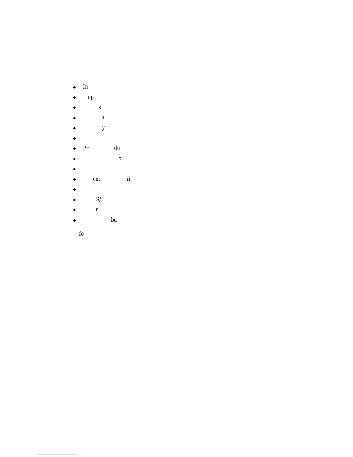
RAID Section
The RAID section is used in TDZ-610 workstations and some InterServe 605 servers.
To replace the RAID section:
1. Before opening the base unit, remove the RAID disk drives from the slots in the RAID section.
Note the order in which the drives are installed.
2. When opening the base unit, remove both left and right side panels.
3. Disconnect the cables attached to the RAID section. Keep track of where each cable was
connected. Refer to the following figure.
4. Remove the screws from the top and both sides of the RAID section. Refer to the following figure.
Page 33

Power
Cables
23
Screws (4)
RAID SCSI
Cable Drive Installed
Cable
5. Slide the RAID section out of the base unit.
6. Slide the new RAID section into the base unit.
7. Secure the RAID section using the eight screws removed previously.
8. Connect the cables to the RAID section.
9. After closing the base unit, install the RAID disk drives into the same slots in the RAID section
from which they were removed.
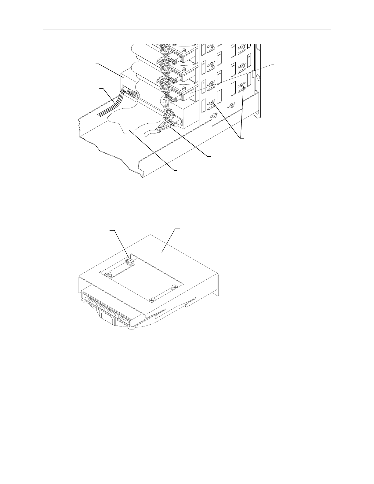
System Hard Disk Drive
To replace the system hard disk drive:
1. Disconnect the cables and remove the bracket screws from the hard disk drive, as shown in the
following figure.
Screw s (2
each side)
Sensor
Cable
2. Remove the chassis screw shown in the following figure.
Page 34

24
Power
Cable
Chassis
Screw
SCSI
Cable
3. Pull the drive forward and lift it out of the base unit, then set the drive on a flat antistatic surface.
4. Remove the bracket from the disk drive.
5. Secure the new disk drive to the bracket.
6. Install the disk drive into the base unit and secure it to the chassis using the chassis screw removed
previously.
7. Connect the SCSI and power cables to the disk drive.
8. Close the base unit.
Riser Card
To remove the riser card:
1. Remove the PCI access panel.
2. Remove the PCI boards connected to the riser card.
3. If ISA option boards are installed, disconnect the SCSI cable and power cables from the top of the
riser card, and remove the ISA I/O lock bracket. Refer to the following figure.
Bracket
Screws
Page 35

SCSI Cable
Power Cable
Connector
Connector
ISA I/O Lock
Bracket
Screw
4. Remove the screw on the pivoting ISA board guide as shown in the following figure.
5. Remove the ISA boards connected to the riser card. Note the position of each board in the ISA
slots.
25
6. Remove the screws shown in the following figure from the peripheral brace. Slide the peripheral
brace to the back of the base unit and remove it.
7. Remove the screw for the air baffle as shown in the following figure; then remove the air baffle.
Riser
Card
Screws
ISA Board
Guide
Peripheral
Brace
Air Baffle
Screws
8. Disengage the riser card from the system board, and remove the card from the base unit.
To install a new riser card:
1. Insert the riser card into its system board slot, pushing firmly over the center of the PCI connectors
to ensure it seats completely.
Page 36

26
CAUTION Do not rock the riser card back and forth; pins inside the connector may be damaged as a result.
Press firmly so the card connector slides evenly into the slot.
2. Replace the peripheral brace. Do not tighten the pivoting ISA board guide until the ISA boards
have been installed.
3. Replace the option boards connected to the riser card. Connect any external cables attached to the
boards. ISA boards must be installed in the same slots from which they were removed.
4. Replace the ISA I/O lock bracket and the PCI access panel.
5. Connect the SCSI and power cables to the riser card, if necessary.
6. Close the base unit.
Processor Module
The processor module contains two CPUs and a Voltage Regulator Module (VRM) for each CPU. The
processor module is replaced as one unit.
To replace the processor module:
1. When opening the base unit, remove the left side panel, and lay the base unit on its right side.
2. Remove the PCI option boards.
3. Remove the screws from the perimeter of the processor module.
4. Disengage the module from the system board connectors.
5. Align the new processor module over the connectors and firmly press it onto the connectors.
6. Secure the module using the screws removed previously.
7. Replace the PCI option boards. They must be installed in the same slots as before.
8. Close the base unit.
P6 Bus Termination Card
To replace the P6 bus termination card:
1. Open the base unit and remove the parts as described in Chapter 1.
2. Ensure the AC power cable is disconnected and the antistatic strap is properly connected.
3. Lay the system on its right side.
4. Remove the installed PCI option boards.
5. Remove the screws that secure the termination card to the system board.
Page 37

P6 Bus Termination
Card
27
6. Carefully disengage the termination card from the connectors.
7. Install the new termination card. The connectors are keyed to ensure proper orientation. Carefully
but firmly push the termination card into the connectors.
8. Secure the termination card with the screws removed previously.
9. Replace the option boards in the same slots from which you removed them.
10. Close the base unit.
System Board
CAUTION The system board is extremely sensitive to static electricity. To prevent serious damage to the system
board, wear the antistatic wrist strap while performing the following steps. Do not open the antistatic
bag containing the system board until instructed.
NOTE Before opening the base unit, run the AMIBIOS Setup program and record all the custom settings for
your system. After replacing the system board, you must run the System Configuration Utility for the
ISA boards. Ensure you have the necessary ISA board configuration files on diskette before you begin.
To replace the system board:
1. Open the base unit and remove the necessary parts as described in Chapter 1.
2. Ensure the AC power cable is disconnected and the antistatic strap is properly connected.
3. Remove the riser card as described previously in “Riser Card.”
4. Remove the processor module as described previously in steps 1 through 4 of “Processor Module”
or the P6 bus termination card as described in steps 1 through 6 of “P6 Bus Termination Card.”
5. Remove the option board fan assembly as described later in “Option Board Fans.”
6. Disconnect all cables attached to the system board. Refer to the following figure for cable
connector locations.
Page 38

28
Internal SCSI
Speaker
Reset
Audio
MIDI
Fan
Assembly
Power
Floppy Cable
Connector
ISA Bus
7. Disconnect the cables from the external ports.
8. Using a three-sixteenth-inch nutdriver, remove the jackscrews from the video, parallel, and serial
ports.
9. Using an 8 mm or five-sixteenth-inch nutdriver, remove the hex nuts from the audio jacks.
Audio
Jacks
10. Using a quarter-inch nutdriver, remove the eight grounding screws from the system board.
11. Slide the system board to the front of the base unit.
12. Lift the board and remove it from the base unit. Set the board on a flat antistatic surface.
Serial Parallel Video
Ports Port Port
Page 39

13. Remove the new system board from the antistatic bag and place it on a flat antistatic surface.
14. Remove the SIMMs from the old system board and install them onto the new system board in the
same configuration.
15. Remove the G95 WRAM module, if installed, and install it onto the new system board.
16. Lower the system board into the base unit. Ensure the standoffs line up with the holes in the
chassis. Slide the system board so the external ports fit into the back panel.
17. Install the jackscrews onto the video, parallel, and serial ports.
18. Install the hex nuts onto the audio jacks.
19. Install the eight ground screws.
20. Install the processor module (or P6 bus termination card).
21. Connect the cables to the system board.
22. Replace the option board fan assembly.
23. Replace the riser card, option board bracket, option boards, and SCSI and power cables.
24. Replace the PCI access panel.
25. Connect the external system cables to the external ports.
29
26. Close the base unit.
27. Run the AMIBIOS Setup utility and change the parameters to your required settings. Refer to the
System Setup.
28. If you have ISA option boards installed, run the System Configuration Utility. Refer to the System
Setup.
System Hard Disk Drive Fan
For systems without the internal RAID subsystem, a small fan beneath the power supply provides
cooling to the system hard disk drive.
To replace the system hard disk drive fan:
1. When opening the base unit, remove the top cover and left side panel.
2. Remove the screws shown in the following figure from the back cover. Pull on the side of the
cover opposite the AC receptacle to disengage it.
CAUTION Do not remove the two screws at the top of the chassis. The power supply could fall, causing damage
inside the base unit.
Page 40

30
AC
Receptacle
Screws
Screws
System Hard Disk
Drive Fan
3. Disconnect the fan power cable from the system board.
4. Remove the fan from the back panel.
5. Attach the new fan to the back panel.
6. Connect the fan power cable to the system board.
7. Replace the back and side panels and the top cover
8. Close the base unit.
Option Board Fans
To replace the option board fans:
1. Remove the peripheral brace.
2. Disconnect the power cables from the system board.
3. The option board fans are removed as a single, self-contained assembly. Remove the fan assembly
screws shown in the following figure; then remove the fan assembly.
Page 41

Screws
4. The option board fans are installed as a single, self-contained assembly. Install the new fan
assembly into the chassis and connect the power cables to the system board.
31
5. Replace the peripheral brace.
6. Close the base unit.
CMOS/Clock Battery
WARNING There is a danger of explosion if the battery is incorrectly replaced. Replace the battery with the
same or equivalent type only, as recommended by the manufacturer. Dispose of used batteries
according to the manufacturer’s instructions.
To replace the CMOS/clock battery:
1. Remove the ISA option boards. The battery is located next to the riser card. Refer to the
following figure.
2. Note the orientation of the battery.
Page 42

32
Riser Card
Battery
3. Carefully remove the discharged battery by grasping it firmly and lifting upward.
4. Install the new battery in the same orientation as the discharged battery.
5. Replace the ISA option board.
6. Close the base unit.
Power Supply
CAUTION Purchase replacement power supplies from Intergraph to ensure proper specifications are met and to
guarantee safety.
To replace the power supply:
1. Remove the AC power cord from the back of the base unit.
2. Disconnect the power cables from the riser card, hard disk drives (or internal RAID subsystem and
DC distribution board), floppy disk drive, and CD-ROM drive.
3. Open the clip that secures the bundle of power cables. Remove the audio cable (connecting the
CD-ROM drive to the system board) from the power cable bundle.
4. Remove the screws securing the power supply to the back of the base unit. Refer to the following
figure.
CAUTION Support the bottom of the power supply with your hand as you remove the screws. Otherwise, the
power supply could fall and cause damage inside the base unit.
Page 43

Screws
33
5. Push the power supply out the side of the base unit.
6. Remove the power switch cable and grounding wire from the chassis.
7. Remove the new power supply from its packaging. On a desktop system, set the AC voltage
switch on the back of the new power supply to the correct voltage for your location.
8. Slide the new power supply into place in the base unit. Mount the power supply using the screws
removed previously.
9. Slide the power cable bundle through the opening; then connect the main power cable to the riser
card.
10. Connect the remaining power cables to the hard disk drives (or internal RAID subsystem and DC
distribution board), CD-ROM drive, and floppy disk drive.
11. Secure the clip around the power cable bundle.
12. Close the base unit.
13. Connect the AC power cord to the back of the base unit.
Power Distribution Board
NOTE The power distribution board is used only in systems which feature the internal RAID section.
To replace the power distribution board:
1. Open the base unit and remove the necessary parts as described in Chapter 1.
2. Remove the power supply as described previously in steps 1 through 7 of “Power Supply .”
3. Disconnect the fan power cable from the system board.
Page 44

34
4. Using a quarter-inch nutdriver, remove the screw (next to the power distribution board) securing
the fan assembly to the base unit.
5. Push the fan assembly towards the internal RAID subsystem and lift the assembly out of the base
unit.
6. Disconnect the cables from the power distribution board. Keep track of the cables which attach to
the various connectors.
7. Using a No. 1 Phillips screwdriver, remove the screws securing the power distribution board to the
base unit.
8. Remove the board from the base unit.
9. Attach the new power distribution board to the base unit.
10. Replace the fan assembly.
11. Connect the cables to the power distribution board.
NOTE Refer to Chapter 7, “Power Supplies, Power Distribution Board, and Fans,” if you need details about
cable connections to the power distribution board.
12. Replace the power supply.
13. Close the base unit.
Page 45

4 Upgrading the System
This chapter describes upgrading your system by adding memory, internal or external SCSI devices,
and option boards. When adding ISA option boards, see also the instructions for using the System
Configuration Utility (SCU).
Adding Memory
Intergraph’s memory upgrade kit contains two Single Inline Memory Modules (SIMMs) and a
disposable antistatic wrist strap.
CAUTION System memory modules available from Intergraph have been certified for use with Intergraph
computers at extremes of temperature and system load to ensure reliable performance. System
memory modules available from other vendors may function improperly or unreliably in your Intergraph
computer.
To avoid damaging the SIMMs and voiding the warranty, take the following precautions.
u
Do not bend, twist, drop, or otherwise handle the SIMMs carelessly.
35
u
Do not expose the SIMMs to moisture or extreme temperatures.
u
Do not remove the SIMMs from the antistatic bag until instructed.
Follow these SIMM population rules to correctly install the SIMMs.
u
All SIMMs in the sockets must be the same memory size.
u
Two, four, or eight SIMMs must be installed in the sockets. The system will not configure itself if
only three, five, six, or seven SIMMs are installed in the sockets.
To install a memory upgrade:
1. Remove the graphics boards and the installed PCI option boards.
2. If installing 128 MB SIMMs in a deskside system, remove the board guide for PCI slot 6 to allow
for the extra height of these large SIMMs. Remove the top screw from the board guide assembly,
then remove the assembly from the chassis. Refer to the following figure.
3. Remove the side screw securing the slot 6 board guide to the board guide assembly; then remove
the board guide. Refer to the following figure.
Page 46

36
Top Screw
Board Guide
Assembly
Side Screw
PCI Slot 6
Board Guide
4. Remove the existing SIMMs from their sockets before adding new ones.
5. Remove the SIMMs from their antistatic bag and install them in this order:
u
If you are installing two SIMMs, install them in the Bank 0 sockets.
u
If you are installing four SIMMs, install them in the Bank 1 sockets first, and then in the Bank
0 sockets.
u
If you are installing eight SIMMs, install the first SIMM in Bank 3 socket J58. Install each
remaining SIMM in the next empty socket until Bank 0 socket J51 is the last socket populated.
Page 47

Bank 0
Bank 1
37
Bank 2
Bank 3
(Socket J58)
Bank 1
Bank 0
(Socket J51)
Bank 3
Bank 2
6. Position the SIMM in the next available socket so that the notch faces the back of the base unit.
7. Insert the SIMM at a 60 degree angle, pressing it firmly into the socket.
8. Push on the top edge of the SIMM until it snaps into the metal clips and locks into the vertical
position. The socket tabs must fit inside the mounting holes of the SIMM.
9. Repeat steps 5 through 7 for each SIMM.
10. If you installed 128 MB SIMMs in a deskside system, replace the board guide assembly (without
the slot 6 board guide).
11. Replace the graphics boards and PCI option boards.
12. After you close the base unit, restart the system. The new memory is recognized automatically.
Adding Internal SCSI Devices
Desktop systems are equipped with an Ultra SCSI controller for all SCSI devices. You can install
internal Ultra SCSI devices in the drive bays located on the right front side of the base unit. The device
must be a 1-inch high device to fit in these bays. You can install a replacement hard disk drive in the
system hard disk drive bracket between the riser card and power supply. If the hard disk drive is more
than 1-inch high you will not be able to use ISA slot 1. If you install a non-Ultra SCSI device, data
transfer rates are limited to the specification of the device.
Page 48

38
Deskside systems are equipped with an Ultra SCSI controller for internal SCSI devices. The internal
drive bays are located above the floppy disk drive bay. These bays are designed to accommodate
1.0-inch and 1.6-inch high devices. If you install a non-Ultra SCSI device, data transfer rates are
limited to the specification of the device.
CAUTION Connecting a non-compliant SCSI-1 device to a TD/TDZ-x10 or InterServe x05 system may cause your
system to stop working, or lead to other unpredictable results.
To install an internal SCSI device:
1. If a device already occupies the location in which you are adding the new device, remove the
existing device. If installing the device into an empty drive bay, remove the support or slide
bracket from the drive bay.
2. Mount the device to the support or slide bracket, if necessary.
3. If installing a non-bracketed device, slide the device through the faceplate and secure it directly to
the chassis.
If installing a bracketed device, slide the bracket through the faceplate, if installing into one of the
forward drive bays; then secure the bracket to the chassis.
4. If installing into the system hard disk drive bracket in a desktop system, replace the bracket,
ensuring the bracket tabs engage the slots on the peripheral brace.
NOTE ISA Slot 1 can be used only if the system hard disk drive is less than 1.6-inches high.
5. Connect the SCSI cable and power cable to the device. The SCSI cable is keyed to ensure proper
insertion, so that the red stripe (pin 1) is adjacent to the power connector.
6. After closing the base unit, install the device drivers and configure the device according to the
vendor’s instructions, if necessary.
Adding External SCSI Devices
You can add single-ended SCSI devices to the system by connecting them to the SCSI port on the back
of the base unit. Additional SCSI option boards (adapters) can be installed to support external SCSI
devices as well. Refer to the “Adding Option Boards” section later in this chapter to install new
boards.
Cable Length Requirements
The desktop systems are equipped with an Ultra SCSI controller (AIC 7860) for all internal and
external SCSI devices. By default, the controller arbitrates with each device (that is, initiates sync
negotiation) to determine the data rate the device will use to transfer data (5, 10, or 20 MHz). If the
target device complies with the 20 MHz SCSI specification, then the data transfer rate will be 20 MHz.
If another device complies with a different specification, then date transfer will be at the lowest data
rate without changing any settings for the controller or the target device.
The deskside systems use a Fast SCSI-2 controller (AIC-7850) for all external SCSI devices. Fast
SCSI-2 devices comply with the 10 MHz SCSI specification. You should install only Fast SCSI-2
devices to the external SCSI port. If you install an Ultra SCSI device, data transfer rates are limited to
the SCSI-2 specification. If you install a SCSI-1 device, data transfer rates are limited to the
specification of the device.
CAUTION Connecting a non-compliant SCSI-1 device to the system may cause your system to stop working, or
lead to other unpredictable results.
Page 49

39
You can add up to five external single-ended SCSI devices to a desktop workstation, and up to seven
external single-ended SCSI devices to a deskside workstation. The number of devices and length of the
cables used to connect the devices becomes a factor when using Fast SCSI-2 or Ultra SCSI devices.
Ultra-SCSI devices impose shorter cable restrictions than Fast SCSI-2 or SCSI-1. The total length of
the SCSI cabling must not exceed the following:
Number of Devices
SCSI-1 Fast SCSI-2 Ultra SCSI
1 to 4 19.8 feet (6 meters) 9.9 feet (3 meters) 9.9 feet (3 meters)
5 to 7 9.9 feet (3 meters) 9.9 feet (3 meters) 4.9 feet (1.5 meters)
NOTE The SCSI controller (integrated or on an option board) counts as one device.
NOTE The AIC 7860 in the desktop system can be configured to transfer data at Fast SCSI-2 rates for all
devices. This allows Ultra SCSI devices to be installed without being hampered by the Ultra SCSI
cable restrictions. Total cable length can then be extended to the Fast SCSI-2 length. See “Disabling
SCSI Sync Negotiation” later in this chapter to configure the controller.
When attaching drives to the system’s SCSI port on the I/O connector board, the total length of the
SCSI cabling is the sum of all of the following:
u
SCSI bus trace length on I/O expansion board - 12.0 inches (30.5 cm)
u
SCSI cable inside the base unit - 41 inches (104 cm)
u
SCSI cable inside each device (average) - 8 inches, (20 cm)
u
SCSI cable between the base unit and the first device
u
SCSI cable between each device
If attaching SCSI drives to an optional SCSI adapter, the total length of the SCSI cabling is the sum of
all of the following:
u
SCSI cable inside the system (101.6 mm)
u
SCSI cable inside each external device (203.2 mm)
u
SCSI cable between the base unit and the first device
u
SCSI cable between each device
Connecting the Device
To add an external SCSI device:
1. Connect the SCSI cable to the SCSI port on the base unit and to the device.
2. Set the device’s SCSI ID to an unused number (1, 2, 3, 5, or 6). By default, the following devices
use pre-defined SCSI IDs:
− System disk drive uses ID 0.
− CD-ROM drive uses ID 4.
− SCSI bus uses ID 7.
3. Disable or enable the device’s SCSI termination according to the vendor’s instructions. The last
external device on the SCSI cable chain must have SCSI termination enabled. All other external
devices must have SCSI termination disabled.
4. If necessary, install the device drivers and configure the device according to the vendor’s
instructions.
Page 50

40
Disabling SCSI Sync Negotiation
Use the following instructions if you need to disable the SCSI sync negotiation, which forces the
controller to transfer data at a specified rate (slower than its capability) for the target devices.
To disable sync negotiation:
1. Power off the system and reboot into DOS using the SYSUTIL diskette.
2. From the SYSUTIL main menu, select SCSI Select Utility.
3. From the Options box, select Configure/View Host Adapter Settings.
4. Select the SCSI Device Configuration option.
5. Change the Initiate Sync Negotiation values for all the attached SCSI devices
(represented by their SCSI ID number) to no.
6. Set the Maximum Sync Transfer Rate values for the devices to the desired settings. If
changing these settings to extend cable lengths or add more devices, set Ultra SCSI devices to
10.0 or less.
NOTE The Advanced Configuration Option allows you to disable the Ultra SCSI controller. When Ultra SCSI
is enabled, the available sync rates are 20, 16, 13.4, 10. When Ultra SCSI is disabled then 10, 8, 6.7,
5 are available.
7. Press ESC until the Exit Utility dialog displays. Select Yes and press ENTER.
8. Press any key to restart the system.
Adding Option Boards
This section briefly describes the differences between Peripheral Component Interconnect (PCI) and
Industry Standard Architecture (ISA) option boards. Instructions are also provided for installing option
boards on the riser card.
The following figure shows the riser card in a desktop system.
Side One
PCI 1
PCI 2
PCI 3
ISA 2
ISA 3
Side Two
ISA 1
Page 51

PCI 1
PCI 2
PCI 3
PCI 4
PCI 5
PCI 6
41
In deskside systems, PCI boards connect to side 1 of the riser card; ISA boards connect to side 2. The
following figure shows the slots on the deskside riser card.
Side One Side Two
ISA 1
ISA 2
ISA 3
ISA 4
Primary PCI Slots
Some PCI option boards (refer to documentation delivered with the board) must be installed in a
primary PCI slot. In a desktop system, PCI slots 1, 2, and 3 are primary. In a deskside system, PCI
slots 5 and 6 are primary.
PCI Option Boards
PCI option boards do not require manual system configuration when installing the board. The system
BIOS detects the board’s presence during startup and reads information from the board’s configuration
registers to assign the necessary system resources. However, if installing a PCI IDE controller, you
must set jumpers on the controller before installing it into the system, as follows.
Setting jumpers on PCI IDE controller boards:
1. Set the jumpers on single-channel controllers to coordinate the IDE channel to IRQ 14. Set the
jumpers on dual-channel controllers to coordinate the primary IDE channel to IRQ 14, and the
secondary IDE channel to IRQ 15. Use the guide below when setting the jumpers.
Desktop Systems
PCI Slot 1 INT A INT B
PCI Slot 2 INT D INT A
PCI Slot 3 INT C INT D
IRQ14 IRQ15
Deskside Systems
PCI Slot 5 INT A INT B
PCI Slot 6 INT D INT A
2. Install the PCI IDE controller into a primary PCI slot, as follows.
IRQ14 IRQ15
Page 52

42
To install PCI option boards:
1. Remove the blanking plate from an available PCI slot.
2. Install the PCI option board. Press firmly to ensure the board seats completely into the riser card
connector.
3. Mount the board to the chassis using the screw removed in step 1 above.
4. After closing the base unit, restart the system. The new PCI board is recognized and configured
automatically.
ISA Option Boards
ISA boards are not designed with internal registers that define the board’s configuration to the system
during startup. Therefore, you must run the System Configuration Utility (SCU) to define the board to
the system. Run the SCU before installing an ISA board to reserve system resources for the board and
to prevent conflicts with option boards already installed. Refer to “Using the System Configuration
Utility” later in this chapter.
To install an ISA board into a desktop system:
1. Remove the system hard disk drive (or its bracket if the disk drive is not installed).
NOTE ISA Slot 1 can be used only if the hard disk drive is less than 1.6-inches high.
2. If installing the board onto side one of the riser card, remove the blanking plate from the
appropriate slot.
3. If installing the board to side two of the riser card, remove the I/O lock bracket and the blanking
plate from the destination slot, as shown in the following figure.
Blanking
Plate
I/O Lock
Bracket
4. Install the option board. Press firmly to ensure the board seats completely in the slot.
5. Replace the system hard disk drive (or its bracket if the disk drive is not installed).
Page 53

43
To install an ISA board into a deskside system:
1. Loosen the screw to allow the pivoting ISA board guide to swing toward the system fans, as shown
in the following figure.
ISA Board Guide Screw
2. Install the option board. Press firmly to ensure the board seats completely in the slot.
3. Slide the pivoting ISA board guide over the edge of the ISA board; then, tighten the screw.
4. Secure the board to the chassis with the screw, and install the I/O lock bracket.
5. After closing the base unit, restart the system.
You may need to load device drivers to enable the new option board to operate. If so, refer to the
documentation provided with the option board.
Using the System Configuration Utility
The System Configuration Utility (SCU) is an MS-DOS utility that will not run in the Windows NT
environment. Use the System Utilities (SYSUTIL) diskette delivered with your system to boot the
system into MS-DOS. The system must be set to boot from the floppy disk drive (normally drive A) to
use the SCU. If necessary, follow the procedure documented in System Setup to change the
workstation boot sequence.
ISA Boards with a Configuration File
Some ISA boards are shipped with a diskette containing a configuration file. The configuration file can
be loaded to the system so that the BIOS reads this file to assign resources during startup. If you install
ISA boards that are shipped with a configuration diskette, follow this procedure.
NOTE If a configuration diskette is not delivered with the option board, refer to “ISA Boards without a
Configuration File” later in this chapter.
Page 54

44
To define ISA boards with a configuration file:
1. Shut down and power off the system.
2. Insert the SYSUTIL diskette into the floppy diskette slot of the combo drive; then restart the
system.
3. When the MS-DOS Startup menu displays, select the System Configuration Utility option.
4. Use the arrow keys or the mouse to select Step 2 from the SCU Main Menu. Then press
add a board that was not detected or has not been installed.
A prompt displays, requesting that you copy the configuration files needed to configure the system.
The configuration file is on a diskette provided by the ISA board manufacturer.
5. Press
ENTER to accept A:\ as the path to the configuration file.
6. Select the slot where the board will be installed. Only slots 1 through 3 are valid for the desktop
system, and slots 1 through 4 are valid for the deskside system.
7. When prompted to insert the source disk, insert the diskette containing the configuration file and
press
ENTER.
When prompted to insert the destination disk, insert the SYSUTIL diskette and press
configuration file from the option board manufacturer will be installed to the system and to the
SYSUTIL diskette.
8. Press
ESC to return to the SCU Main Menu.
9. Select Step 4 from the SCU Main Menu to save the configuration, and then select Step 6 from the
SCU Main Menu to exit the SCU.
10. Remove the diskette from the combo drive; then restart the system.
ISA Boards without a Configuration File
Some ISA board vendors do not include configuration files with their boards. For these boards, you
must use the SCU to define the ISA board to the system (that is, manually create a configuration file)
by following this procedure.
INSERT to
ENTER. The
To define ISA boards without a configuration file:
1. Shut down and power off the system.
2. Insert the SYSUTIL diskette into the floppy diskette slot of the combo drive; then restart the
system.
3. When the MS-DOS Startup menu displays, select the System Configuration Utility option.
4. From the SCU Main Menu, select Step 2, then press
F6. The ISA Board Definition Menu displays.
5. Enter the data specified in the manufacturer’s configuration instructions.
NOTE Use the TAB and arrow keys to move the cursor from field to field. Once inside the DMA, IRQ, and
Ports fields, press ENTER to display the sub-fields for entering the information.
6. Press F10 to save the data to the system.
7. Press
8. Press
ENTER to return to the ISA Board Definition Menu.
ESC to return to the SCU Main Menu.
9. Select Step 2 from the SCU Main Menu. The Add and Remove Boards Menu displays.
10. Select the required slot number and press
INSERT.
Page 55

11. Select INSERT to add the board. The ISA Board Database Menu displays.
45
12. Select the correct board name and press
ENTER.
13. When the Slot Selection Menu displays, select the required slot and press
14. Press
ESC to return to the SCU Main Menu.
15. Select Step 4 from the SCU Main Menu to save the configuration.
16. Select Step 6 from the SCU Main Menu to exit the SCU.
17. Remove the diskette from the combo drive; then restart the system.
ENTER.
Page 56

46
Page 57

5 System Board
This chapter provides information about the system board (MSMT359), including the following:
u
Components and chipsets
u
Cable connectors
u
Address configuration
u
External ports
The system board provides the following system functionality:
u
Processors - one to four Intel Pentium Pro 200 MHz, each with 512 KB L2 cache
u
PCI Bridge - Intel Orion PCI bridge provides the interface between the processors and PCI
expansion bus
u
PCI to ISA Bridge - Intel 82379AB provides the interface between the ISA expansion bus and the
PCI bus
u
Memory - eight memory sockets and Intel memory controllers support up to 1 GB of four-way
interleaved memory
47
u
Networking - Intel 82557 provides Ethernet 10Base-T or 100Base -TX protocol, autodetects
network type
u
SCSI - Adaptec 7860 Ultra SCSI controller supports external SCSI drives
u
System I/O - Standard Microsystems Corporation FDC37C932 Super I/O Controller supports
mouse, keyboard, floppy disk drive, Real Time Clock, Non-Volatile RAM, serial ports, and
parallel port
Page 58

48
Accelerator
Memory Sockets
Components and Chipsets
The following figure shows the locations of the major integrated components and the jumper
connectors.
PCI
Bridge
CPU Frequency
Jumpers
Sound
Processor
Lithium
Battery
Ethernet
Controller
SCSI
Controller
PCI to
ISA
Bridge
Flash
EEPROM
OMCDC
J25
VGA Mode Jumper
Graphics
J16
BIOS Jumper
I/O
Controller
OMCDP
MICMICMICMIC
Memory
Controllers
Window
RAM
Palette
DAC
Page 59

Lithium Battery (CMOS/Clock Battery)
When the system is off, the Lithium battery on the system board provides power to the real time clock
and BIOS flash EPROM, which stores the BIOS information. As long as the system is running, the
batteries are not used to sustain the information. If the battery fails, the system date and time will be
lost and the BIOS will not be installed when the system is rebooted. To replace a failed battery, refer
to Chapter 2, “Servicing the Desktop System” or Chapter 3, “Servicing the Deskside System.”
Graphics Chipset
G95 Accelerator
The graphics accelerator (Matrox MGA-2064W) interfaces to the system board through the PCI bus.
This accelerator supports all of the standard VGA graphics modes in addition to native modes capable
of resolutions up to 1600 x 1200. The frame buffer interface is 64 bits wide and is clocked at 100
MHz. Color depths of 4, 8, 16, 24, and 32 bits are supported, allowing a resolution of 1280 x 1024 (24
bit color depth) in only 4 MB of frame buffer memory. Features such as bit block transfer (BitBlt),
Line Draws, and Fills provide hardware acceleration for Windows. Video playback is accelerated
through scaling and YUV to RGB color space conversion.
Palette DAC
49
The palette DAC operates up to 175 MHz and converts the digital RGB data in the frame buffer to
analog signals for the monitor. The device includes two fully programmable phase-locked loop clock
sources for both the memory clock and the pixel clock.
Window RAM
Window RAM (WRAM) is the video memory used by the MGA-2064W. The graphics frame buffer
consists of two 256K x 32 WRAM components for 2 MB of video memory. WRAM is a dual-ported
video memory specially designed to accommodate common drawing functions, offering higher graphics
performance at a lower cost than standard Video RAM.
Starting with 2 MB WRAM, a 2 MB or 6 MB WRAM mezzanine module can be added for improved
video performance. 8 MB of WRAM is the maximum amount configurable. Memory above 2 MB
increases the number of colors available at each resolution, enabling you to work in true color mode at
higher resolutions. Increased WRAM also improves color acceleration by providing extra caching
memory for storing off-screen fonts and images.
VGA Mode Jumper
The VGA mode jumper (J25) enables or disables the G95 VGA mode on motherboards equipped with
the G95 graphics chipset. By default, the jumper is not installed (OFF), which enables VGA mode. If
the jumper is installed (ON), the VGA mode is disabled.
NOTE You must remove the PCI option boards and the processor module (or P6 bus termination card) to
access the VGA mode jumper.
Page 60

50
SCSI Controller
The SCSI controller is the Adaptec Ultra SCSI Adapter (AIC-7860), which provides a single-ended bus
for SCSI-1, Fast SCSI-2, and Ultra SCSI devices. The SCSI bus is dedicated to the hard disk drives
and CD-ROM drive. The SCSI bus actively terminates on the system board and at the end of the
internal SCSI cable. The AIC-7860 supports low-speed devices to allow legacy SCSI devices to be
used with the system. By default, the controller functions in Fast SCSI-2 mode rather than Ultra mode.
I/O Controller
The Standard Microsystems Corporation (SMC) Super I/O Controller (FDC37C932) integrates mouse,
keyboard, serial, parallel (multi-mode), floppy (2.88 MB), and Real-Time Clock (RTC) functions into
one chip.
Serial Port
The FDC37C932 supports four serial ports via two external port connectors (COM 1 and COM 2).
COM1 can be configured as COM1 or COM3; COM2 can be configured as COM2 or COM4. The
serial ports use the system I/O addresses shown below.
Port
Addresses Interrupts
COM1 3F8-3FF IRQ4
COM2 2F8-2FF IRQ3
COM3 3E8-3EF IRQ4
COM4 2E8-2EF IRQ3
The addresses for each serial port can be configured in AMIBIOS Setup, as described in the System
Setup. Do not assign more than one device to the same COM port number. Serial port problems occur
because a serial port and another device are assigned to the same COM number. The system and the
connected serial device must be set to the same communications parameters (baud rate, parity, number
of data bits, and number of stop bits). Refer to the serial device documentation for information about
setting these parameters.
Parallel Port
The parallel port functionality of the FDC37C932 includes the following modes:
u
Normal mode (or Compatibility mode) - an industry-standard parallel interface mode. Normal
mode provides an asynchronous, byte-wide forward channel (host to peripheral), and is the base
mode common to all compliant interfaces.
u
SPP mode (or Byte or Bi-Dir mode) - compatible with IBM PS/2 hosts. SPP is an asynchronous,
byte-wide reverse channel (peripheral to host) mode using the eight data lines of the interface for
data, and the control/status lines for handshaking. Transfer direction is controlled by the host
when the peripheral and the host both support bi-directional use of data lines.
u
EPP mode - provides an asynchronous, byte-wide, bi-directional channel controlled by the host
device. This mode also provides separate address and data cycles over the eight data lines of the
interface. EPP increases the data transfer performance to 2 MB per second while retaining
backward compatibility with existing AT and PS/2 compatible interfaces.
u
ECP mode - similar to EPP, providing an asynchronous, byte-wide, bi-directional channel
controlled by the host device. Additionally, ECP implements a control line to distinguish between
command and data transfers. A command may optionally be used to indicate single byte data
compression or channel address. Other ECP mode features include:
Page 61

−
Supports 2 MB per second data transfer rate
−
High performance, half duplex, forward and reverse channel
−
Interlocked handshake for fast, reliable data transfer
−
Channel addressing for low-cost peripherals
−
Link and data layer separation
−
Active output drivers and adaptive signal timing
−
Peer-to-peer capability
The addresses and interrupts used by the external parallel port can be assigned in AMIBIOS Setup.
Refer to the System Setup for information to configure the ports. The parallel port addresses and
interrupts are shown in the following table.
51
Port
Address Interrupt
LPT1 378-37A IRQ7 or IRQ5
LPT2 278-27A IRQ7 or IRQ5
LPT3 3BC-3BE IRQ7 or IRQ5
Processor Components
Processors
The system uses one or two processors installed on the system board. Each processor is 180 MHz or
200 MHz Pentium Pro with 512 MB secondary cache. Quad-processor systems use a processor card
(MSMT310) to add two more processors. When only one or two processors are installed, the P6 bus
termination card (MSMT311) is installed instead of the processor module. The termination card
provides bus termination for the P6 bus.
Processor Jumpers
Jumpers are used to set the processor to clock speed ratio for the system. The default, certified
configuration is a ratio of 3:1 (3x multiplier). The 180 MHz CPU uses a 60 MHz P6 bus, with jumpers
installed to obtain the 3x multiplier. The 200 MHz CPU uses a 66.67 MHz P6 bus, with jumpers
installed to obtain the 3x multiplier. The following table shows the jumper settings to obtain the 3x
multiplier. IN denotes the jumper is installed on both pins.
CPU 0 Frequency
CPU 1 Frequency
Jumper Setting Jumper Setting
J63 OUT J49 IN
J62 IN J50 IN
J61 IN J47 IN
J60 IN J48 OUT
CAUTION Do not change the jumper settings in an attempt to change CPU speed. The CPUs will only operate
properly when the jumpers are installed in their default settings.
Page 62

52
The following figure shows the detail of the CPU frequency jumper connectors.
CPU 0
VRM
Jumpers for CPU 0
J63
J62
J61
J60
NOTE The processor module does not use configurable jumpers.
CPU 1
Jumpers for CPU 1
J49
J50
J47
J48
PCI Bridge
The PCI bridge chip (Intel 82454) provides high-bandwidth PCI compatibility for the system. The
bridge chip supports the primary PCI bus and is the path by which processors have access to all PC
compatible devices such as the ISA bus, BIOS PROM, and graphics controller. PCI slots 5 and 6 are
on the primary PCI bus. PCI slots 1 through 4 (secondary) are supported by an Intergraph
programmable part on the riser card.
PCI to ISA Bridge
The Intel 82379AB System I/O-APIC (Advanced Programmable Interrupt Controller) bridges the ISA
bus off the Primary PCI bus (PCI bus 0). The 82379AB supports all four ISA expansion slots.
Memory Components
Memory Sockets
The system board contains eight memory sockets which accept 72 pin SIMMs from Intergraph. The
sockets are divided into four banks. When all sockets are populated, the memory is four-way
interleaved which results in maximum memory performance. Refer to Chapter 4 for instructions to
upgrade memory. The following figure shows the socket numbers and bank organization.
Page 63

53
J58
13203210Banks -
CPU 0
J51
CPU 1
Memory Controllers
The Orion memory components (OMC) include the OMC-DP (data path) and the OMC-DC (data
control). The OMC-DP provides a consolidated memory data path between the P6 bus and the memory
interface chips (MICs). The MICs provide the interface between the P6 bus (via the OMC-DP) and the
installed memory modules. Each MIC handles 1/4 of the memory data path, and is optimized for
interleaved performance using read-around writes and data buffering. The OMC-DC is an addressing
and control device for the DRAM array that interfaces to the OMC-DP.
BIOS Components
Flash EPROM
The system board (MSMT329) uses a flash EPROM chip (MYPG782) for the system’s Basic
Input/Output System (BIOS). The System Setup Guide contains information about reprogramming the
flash EPROM with a new BIOS when necessary. It also defines the features of the AMIBIOS Setup
program, used to modify the BIOS parameters.
BIOS Jumper
The BIOS jumper (J16) allows the BIOS password to be bypassed. By default, the jumper is OFF,
which enables the password. When the jumper is ON, the password is disabled.
NOTE You must remove the PCI option boards and the processor module (or P6 bus termination card) to
access the BIOS jumper.
Page 64

54
Sound Controller
The sound controller is the Vibra 16C chip from Creative Labs. Integrated onto the system board, the
controller is a complete, full-feature MPC 2.0 compliant sound implementation, providing full Sound
Blaster Pro functionality and compatibility. The sound controller has the following features and
specifications:
Feature
Sound Controller Creative Labs Vibra 16C
Audio Resolution 16-bit
Sound Blaster Compatibility Sound Blaster Pro, with Sound Blaster 16 register
MIDI/UART Mode/
Compatibility
Bus Interface 16-bit ISA
CODEC 16-bit Sigma Delta Stereo
CODEC FIFO 4 Samples
FM Synthesizer Yamaha OPL3
External Audio Inputs Microphone (Monoral), Stereo Line-In
Internal Audio Inputs Stereo FM Synthesis, Stereo Wave Data, Stereo
Audio Outputs Stereo Line-Out
MIDI/Joystick MIDI In, MIDI Out, Up to 4 fire buttons
ADPCM Audio Compression 4:1, 3:1, and 2:1
Sampling Rate Range 5 KHz - 44.1 KHz in 228 selectable steps
Selectable Microphone AGC Yes
Microphone Support Low-Impedance (600 Ohms) Dynamic, Electek
Specification
compatibility
Roland MPU401
CD, Monoral PC Speaker
The Vibra 16C sound controller is configured entirely through I/O port accesses. When the system is
powered up, the hardware forces the Vibra 16C to respond to default I/O port addresses, interrupt
request (IRQ) level, and direct memory access (DMA) request and acknowledge. The following table
shows the default sound controller configurations and available programmable settings.
Parameter
Base I/O Address / MPU-401 220/330 240/300
8-bit DMA Req / Ack Level 1 3
16-bit DMA Req / Ack Level 5 7
Interrupt Request Level 10 5, 7
The settings above may be changed in AMIBIOS Setup (see “Chipset Setup” in the Setup and
Maintenance Guide, delivered with the system) so the Vibra 16C internal registers respond to custom
settings.
Default Other Available
Page 65

Cable Connectors
The following figure shows the internal connector locations. Verify Pin 1 location for each connector
on the system board.
NOTE For the power connectors, refer to “Power Supply Information” in this chapter.
The following figure shows the location of the cable and jumper connectors. The CPU, VRM, memory
sockets, and riser card connectors are provided for reference.
55
SCSI -
J43
CPU 0
ISA Bus -
J32
VRM 0
ISA Bus J33
CPU 1
VRM 1
Floppy -
J30
Memory Sockets
Riser Card
Connectors
J74
J71
J68
Audio - J22
MIDI - J17
Page 66

56
Floppy Pinout
All odd pins are connected to ground.
Signal
RPM 2 DRV0- 14 TRK0- 26
No connect 4 MTR1- 16 WRPRT- 28
DRATE0 6 DIR 18 RDATA- 30
INDEX- 8 STEP- 20 HDSEL 32
MTR0- 10 WDATA- 22 DSKCHG 34
DRV1- 12 WGATE- 24
Audio Pinout
Signal Pin
Right Sound Channel 1
Ground 2
Left Sound Channel 3
Ground 4
ISA Bus J32 Pinout
Signal Pin Signal Pin Signal Pin
IRQ15 1 SD+(0) 15 Ground 28
IRQ14 2 SD+(1) 16 RSTDRV 29
IRQ10 3 SD+(4) 17 Ground 30
IRQ3 4 SD+(5) 18 SA+(6) 31
IRQ7 5 MEMW- 19 SA+(7) 32
IRQ9 6 MEMR- 20 SA+(10) 33
IOCS16- 7 SA+(17) 21 SA+(11) 34
Ground 8 SA+(18) 22 SA+(14) 35
IOCHRDY+ 9 SA+(21) 23 SA+(15) 36
Ground 10 SA+(22) 24 BALE 37
SD+(14) 11 SA+(1) 25 IOR- 38
SD+(15) 12 Ground 26 D7BUFDIR 39
SD+(11) 13 SA+(3) 27 PWR_DWN 40
SD+(10) 14
Pin Signal Pin Signal Pin
Page 67

ISA Bus J33 Pinout
Signal Pin Signal Pin Signal Pin
Spare 1 SD+(2) 15 Ground 28
IRQ11 2 SD+(3) 16 SA+(4) 29
IRQ4 3 SD+(6) 17 SA+(5) 30
IRQ5 4 SD+(7) 18 SA+(8) 31
0WS- 5 SA+(19) 19 SA+(9) 32
Ground 6 SA+(20) 20 SA+(12) 33
MEMCS16- 7 SA+(23) 21 SA+(13) 34
Ground 8 SBHE- 22 SA+(16) 35
SPKR- 9 SA+(0) 23 AEN 36
Ground 10 Ground 24 IOW- 37
SD+(13) 11 SA+(2) 25 Ground 38
SD+(12) 12 Ground 26 LOBUFDIR 39
SD+(9) 13 ISA BCLK 27 HIBUFDIR 40
SD+(8) 14
57
Address Configuration
DMA Channels
The system board uses Direct Memory Address (DMA) channels to exchange data without accessing
the CPU. Some channels are assigned for specific use by the system, as defined below. Each DMA
channel appropriates full 32-bit processing. For an ISA bus, channels 0 through 3 are 8-bit and
channels 4 through 7 are 16-bit channels.
DMA
0 Spare 4 Cascade input for 0-3
1 Vibra 16C Controller 5 Vibra 16C Controller
2 I/O Controller 6 Spare
3 Parallel Port 7 Spare
Input/Output Addresses
The following table lists a small subset of the reserved I/O addresses.
Address
0278 - 027F Parallel Port LPT2
02E8 - 02EF Serial Port COM4
02F8 - 02FF Serial Port COM2
0378 - 037F Parallel Port LPT1
03B0 - 03BF Monochrome Display/Printer Adapter
03C0 - 03CF Enhanced Graphics Adapter (EGA/VGA)
03D0 - 03DF Color/Graphics Monitor Adapter (CGA/MCGA)
Assignment DMA Assignment
Device
Page 68

58
Address Device
03E8 - 03EF Serial Port COM3
03F0 - 03F7 I/O Controller
03F8 - 03FF Serial Port COM1
Memory A ddress Map
The following table lists the memory address map assignments.
Memory Address
00000000 - 0009FFFF 640K System board memory
000A0000 - 000BFFFF 128K Video memory
000C0000 - 000C7FFF 32K Video ROM
000C8000 - 000DFFFF 96K Available I/O Adapter ROM
000E0000 - 000EFFFF 64K BIOS ROM and PCMCIA
000F0000 - 000FFFFF 64K BIOS ROM
00100000 - 0FFFFFFF 256M Expansion memory
10000000 - 3FFFFFFF ----- Reserved
PCI to ISA Bus Interrupt Mapping
The ISA bridge (Intel 82379AB) provides the sixteen conventional ISA interrupts, plus four interrupt
request pins for PCI peripheral interrupts (PIRQ0 through PIRQ3). For PC-AT architecture
compatibility reasons, the PCI interrupts are routed to the ISA interrupts within the ISA bridge. The
assertion of a PCI interrupt concludes in an ISA interrupt being asserted.
The 8-bit PIRQ Route Control Registers in the ISA bridge determine to which ISA interrupt a PIRQ is
routed. Four PIRQ Route Control Registers are used for the PCI interrupts, located at the ISA bridge
address offsets defined below.
PCI Interrupt Request
PIRQ0 60
PIRQ1 61
PIRQ2 62
PIRQ3 63
Address Offset (Hex)
Size Assignment
Bit 7 of each PIRQ registers enable (Low) or disable (High) the routing of the PIRQ to an ISA
interrupt. The lowest four bits (3:0) of each PIRQ register determines to which ISA interrupt the PIRQ
will be routed, as defined below.
Bits (3:0) of PIRQ
0000 Reserved 1000 Reserved
0001 Reserved 1001 IRQ9
0010 Reserved 1010 IRQ10
0011 IRQ3 1011 IRQ11
0100 IRQ4 1100 IRQ12
0101 IRQ5 1101 Reserved
ISA Interrupt Bits (3:0) of PIRQ ISA Interrupt
Page 69

Bits (3:0) of PIRQ ISA Interrupt Bits (3:0) of PIRQ ISA Interrupt
0110 IRQ6 1110 IRQ14
0111 IRQ7 1111 IRQ15
PCI Bus Configuration Space
The table below lists the configuration space used for the primary PCI bus. The PCI bus uses type 1
configuration access, which specifies two 32-bit I/O ports used as the index register (0CF8h) and the
data register (0CFCh).
59
Device
Host-to-PCI Bridge (PCMC) 0 800000XX
PCI-to-ISA Bridge 2 800010XX
Graphics Accelerator 5 800028XX
Ethernet Controller 6 800030XX
SCSI Controller 7 800038XX
PCI Slot 1 D 800068XX
PCI Slot 2 E 800070XX
PCI Slot 3 F 800078XX
Each PCI slot on the riser card has four available interrupt lines: INTA, INTB, INTC, and INTD.
These are connected to the PCI interrupts PIRQ0 through PIRQ3, as shown below:
Interrupt Line
INTA PIRQ0 PIRQ1 PIRQ2 PIRQ3 PIRQ0 PIRQ1
INTB PIRQ1 PIRQ2 PIRQ3 PIRQ0 PIRQ1 PIRQ2
INTC PIRQ2 PIRQ3 PIRQ0 PIRQ1 PIRQ2 PIRQ3
INTD PIRQ3 PIRQ0 PIRQ1 PIRQ2 PIRQ3 PIRQ0
Slot 1 Slot 2 Slot 3 Slot 4 Slot 5 Slot 6
ISA Bus IRQ Assignments
The ISA slots on the riser card accommodate ISA based option boards and a 16-bit wide expansion
bus. The ISA bus interrupt (IRQ) assignments are defined below.
Device Number 0CF8h Value
IRQ
0 System Timer 0 8 Real Time Clock
1 Keyboard Full 9 Spare
2 Cascade input for IRQ8 - IRQ15 10 Vibra 16C Controller
3 COM2, COM4 11 Spare
4 COM1, COM3 12 Mouse
5 Spare 13 Not Available
6 I/O Controller 14 Spare
7 Parallel Port 15 Spare
Name IRQ Name
Page 70

60
The spare interrupts listed above may be assigned to PCI and ISA devices. When you add a PCI device
to the system, the interrupt will be automatically assigned by the system BIOS. However, at least one
interrupt must be available for the PCI bus. For increased performance, one interrupt should be left
available for each PCI based controller used in the system. When you add a ISA board, you must
assign the interrupt using the System Configuration Utility and jumpers on the option board.
External Ports
The following figures show the external ports in their proper orientation, when the base unit is in the
upright position.
MIDI Pinout
15
9
Ethernet Pinout
1
8
1
8
Pin Signal Pin Signal
1 +5V 9 +5V
2 Fire button 0 10 Fire button 2
3 X-axis, joystick 1 11 X-axis, joystick 2
4 Ground 12 MIDI out
5 Ground 13 Y-axis, joystick 2
6 Y-axis, joystick 1 14 Fire button 3
7 Fire button 1 15 MIDI in
8 +5V
Pin Signal Pin Signal
1 TD+ - Transmit 5 Reserved
2 TD– - Transmit 6 RD– - Receive
3 RD+ - Receive 7 Reserved
4 Reserved 8 Reserved
Page 71

Serial (COM) Pinout
61
6
9
Mouse and Keyboard Pinout
2 4 6
1 3 5
1
5
Pin Signal
1 DCD - Data Carrier Detect
2 RD - Receive Data
3 TD - Transmit Data
4 DTR - Data Terminal Ready
5 Ground
6 DSR - Data Set Ready
7 RTS - Request to Send
8 CTS - Clear to Send
9 RI - Ring Indicator
Mouse Keyboard
Pin Signal Pin Signal
1 MDATA 1 KDATA
2 Reserved 2 Reserved
3 Ground 3 Ground
4 Fused VCC -
+5V
5 MCLK 5 KCLK
6 Reserved 6 Reserved
4 Fused VCC -
+5V
Video Pinout
5 10 15
1 6 11
Pin Signal
1 R - Red
2 G - Green
3 B - Blue
4 MID2 - Monitor ID2
5, 6, 7, 8, 10 Ground
9 No Connect
11 MID0 - Monitor ID0
12 MID1 - Monitor ID1
13 HSYNC - Horizontal Sync
14 VSYNC - Vertical Sync
15 MID3 - Monitor ID3
Page 72

62
SCSI Pinout
50
26
25
1
Pin Signal
26 Command Data-0
27 Command Data-1
28 Command Data-2
29 Command Data-3
30 Command Data-4
31 Command Data-5
32 Command Data-6
33 Command Data-7
34 Command Data Parity
38 Terminator Power
41 Attention
43 Busy
44 Acknowledge
45 Reset
46 Message
47 Select
48 Command
49 Request
50 Input/Output
Note Pins 12, 13, 14, 37, and 39 are not connected; all other pins not listed are connected to ground.
Parallel Pinout
14
25
1
13
Pin Signal Pin Signal
1 -Strobe 10 -ACK -
Acknowledge
2 Data 0 11 Busy
3 Data 1 12 PE - Paper Empty
4 Data 2 13 +Select
5 Data 3 14 -Auto FDXT -
Auto Feed
6 Data 4 15 -Error
7 Data 5 16 -Init - Start
8 Data 6 17 -SLCTIN - Select
9 Data 7 18-25 Ground
Page 73

6 Riser Cards
This chapter describes the riser cards for the desktop and deskside systems.
Desktop Riser Card (MSMT345)
63
Side One
PCI 1
PCI 2
ISA 1
PCI 3
ISA 2
ISA 3
Side Two
Expansion Slots
The riser card has three PCI slots and three ISA slots. All PCI slots are on the primary PCI bus,
supported by the PCI bridge on the system board.
Graphics Card Slot Assignments
Graphics card are installed in specific PCI slots on the riser card. The following chart specifies the
slots where graphics boards are located.
NOTE Systems with on-board graphics use G95 accelerator on the system board, rather than an installed PCI
card.
Millennium II
Dual Screen (DS)
Slot 2
Slot 3
Slot 1
Slot 2
Slot 3
Slot 1
Slot 2
Slot 3
Millennium II card
(second screen)
Intense 3D (I3D)
I3D card I3D card I3D card I3D card
Z10
Z10 card Z10 card Z10 card
Millennium II
A la Carte
Millennium II card Millennium II card
I3D, DS I3D with Geometry (G) I3D-G, DS
I3D card I3D card
Z10, DS Z10 with Texture
Z10 card
Millennium II
A la Carte, DS
Millennium II card
(first screen)
(second screen)
Geometry accelerator Geometry accelerator
Texture card
Page 74

64
Z13 Z13 with Geometry Z25 Z25 with Geometry
Slot 1
Slot 2
Slot 3
Z13 card Z13 card Z13 card Z13 card
VGA board VGA board VGA board VGA board
Geometry accelerator Geometry accelerator
Deskside Riser Card (MSMT280, MSMT463)
Power Connector
SCSI Connector
Side One Side Two
PCI 1
PCI 2
ISA 1
PCI 3
ISA 2
PCI 4
ISA 3
PCI 5
ISA 4
PCI 6
PCI-to-PCI Bridge
SCSI Controller
Expansion Slots
The riser card has six PCI slots and four ISA slot. PCI slots 5 and 6 are on the primary PCI bus,
supported by the PCI bridge on the system board. PCI slots 1 through 4 (secondary) are supported by a
PCI-to PCI bridge (an Intergraph programmable part for MSMT463, or the DEC 21050 chip for
MSMT280). Some PCI option boards must be installed in a primary PCI slot, as stated in the
documentation delivered with the option board.
NOTE Full-length PCI cards cannot be installed in PCI slot 6 if the processor module is installed on system
board MSMT353. The processor module is used in quad-processor systems only.
SCSI Controller and Connector
If the riser card is MSMT280, the system’s internal SCSI devices use the SCSI controller on the system
board (AIC-7860). The SCSI cable for external devices connects to the SCSI connector on the riser
card.
If the riser card is MSMT463, the system’s internal SCSI devices use the SCSI controller on the riser
card (AIC-7880). The SCSI cable for internal devices connects to the SCSI connector on the riser card.
External devices use the SCSI controller on the system board.
Page 75

Graphics Card Slot Assignments
Graphics card are installed in specific PCI slots on the riser card. The following chart specifies the
slots where graphics boards are located.
NOTE Systems with onboard graphics use the G95 accelerator on the system board, rather than an installed
PCI card.
65
Slot 3
Slot 4
Slot 3
Slot 4
Slot 5
Slot 2
Slot 3
Slot 4
Slot 5
Slot 1
Slot 2
Slot 3
Slot 4
Slot 5
Millennium II
Dual Screen (DS)
Millennium II
A la Carte
Millennium II
A la Carte, DS
Millennium II card
(first screen)
Millennium II card
(second screen)
Intense 3D (I3D)
Millennium II card Millennium II card
(second screen)
I3D, DS I3D with Geometry (G) I3D-G, DS
I3D card I3D card
I3D card I3D card I3D card I3D card
Geometry accelerator Geometry accelerator
Z10
Z10, DS Z10 with Texture (T) Z10-T, DS
Z10 card Z10 card Z10 card Z10 card
Z10 card Texture card Texture card
Z10 card
Texture card
Z13
Z13, DS Z13-G Z13-G, DS
Z13 card Z13 card
VGA card VGA card
Z13 card Z13 card Z13 card Z13 card
VGA card VGA card VGA card VGA card
Geometry accelerator Geometry accelerator
Z25
Slot 1
Slot 2
Slot 3
Slot 4
Graphics board Graphics board Graphics board Graphics board
VGA board VGA board VGA board VGA board
Slot 5
NOTE In a TDZ-610, the RAID controller board is installed in PCI Slot 2 if the system also contains the Z25-G
board set.
Z25, DS Z25-G Z25-G, DS
Graphics board Graphics board
VGA board VGA board
Geometry board Geometry board
Page 76

66
Page 77

7 Power Supplies, Power
pp
Distribution Board, and Fans
This chapter provides information for the deskside and desktop power supplies and fans. The power
distribution board information is also included here for systems using the internal RAID section.
Deskside Power Supply (MPWS131)
The TDZ-410, TDZ-610, InterServe 605, and InterServe 605UW systems use the MPWS131 power
supply, which has a maximum output of 539 watts.
NOTE If the system has internal RAID section, a power distribution board is also installed. Refer to “Power
Distribution Board (MPCBD13)” later in this section for more information.
The power supply is switchable (autoranging) between 90-132 VAC or 180-264 VAC, depending on
the location. The input frequency is 47-63 Hz, single phase. At full load, nominal AC line, nominal
power factor of 0.6, and temperature of 25°C, the power supply has a minimum efficiency of 65
percent.
67
DC Output Specifications
The following table details the power supply DC output specifications.
Nominal Output Voltages
Continuous Load (Maximum)
Continuous Load (Minimum)
Noise and Ripple (PARD) (DC
to 30 MHz)
Initial Setting Tolerance
(Maximum)
Regulation Line/Load
(Maximum)
Overshoot - Turn on/off
(Maximum)
Notes:
1. The 539 W power supply meets or exceeds the specifications in the above table. For the noted
specifications, the Maximum values describe the smallest acceptable maximum load, and the
Minimum values describe the largest acceptable minimum load.
2
2,5
2,5
1,5
Outputs
#1 #2 #3 #4 #5 Unit
+3.3 +5.1 +12.0
1
1
3,4
48
06000A
76
3,4
12
4
−
12.0
−
5.0
0.5 0.5 A
50 50 100 250 100 mV
±
3%
±
3%
±
3%
±
3%
±
5%
±
5%
±
±
10%
10%
±
±
10%
10%
5% 5% 10% 10% 10%
V
DC
DC
DC
2. These outputs are measured at the connector of a loaded cable.
3. The +3.3 V and +5.1 V outputs do not draw more than 400 watts combined.
Page 78

68
4. Any combination of +3.3 V, +5.1 V, and +12 V do not exceed their maximum or 539 watts of total
power.
5. The sum of Initial Setting Tolerance and Line/Load Regulation does not exceed 3% for the
+3.3 V output, 3% for the +5.1 V output, 5% for the +12.0 V output, and 10% for the negative
output voltages.
Cable Connectors
The following table shows the cable connectors from the power supply that connect to the riser card
and to the devices in the system.
The following table shows the cable connectors from the power supply that connect to the riser card
and to the devices in the system.
P1 Pinout
Connector
P1 Riser Card P6 Auxiliary Drive
P2 CD-ROM Drive P7 Auxiliary Drive
P3 Auxiliary Drive P8 Auxiliary Drive
P4 Auxiliary Drive
P5 Auxiliary Drive
Pin Signal Wire Color Pin Signal Wire Color
1 +3.3V Orange 13 +5V Red
2 +3.3V Orange 14 Ground Black
3 +3.3V Orange 15 Ground Black
4 Ground Black 16 +5V Red
5 Ground Black 17 Ground Black
6 Ground Black 18 -12V Blue
7 +3.3V Orange 19 +5V Red
8 +3.3V Orange 20 -5V Red
9 +5V Red 21 Ground Black
10 Ground Black 22 +12V Yellow
11 +5V Red 23 Ground Black
12 Ground Black 24 Power
Device Connector Device
(or RAID section)
P9 Combo Drive
(or RAID section)
Green
Good
P2 - P8 Pinout
Pin Signal Wire Color
1 +12V Yellow
2 Return Black
3 Return Black
4 +5V Red
Page 79

P9 Pinout
Pin Signal Wire Color
1 +5V Red
2 Return Black
3 Return Black
4 +12V Yellow
Power Distribution Board (MPCBD13)
The power distribution board is only used in systems with the internal RAID section. These systems
include the internal RAID section, and require special power signal routing.
Cable Connectors
The following figure shows the MPCBD13 cable connectors.
69
J10
J19
J13
J10, Power
Pin
1 +12V Yellow
2 Return Black
3 Return Black
4 +5V Red
J13, RAID Sensor
Pin
1,2,3,4 +5.1V 22 Not used 34 Drive 3 Status
6 Dskbad 24 Not used 36 Drive 4 Status
8 Dskgood 26 Alarm Reset 38 Drive 5 Status
10 Alarm 30 Drive 1 Status 40 Drive 6 Status
Signal Wire Color
Signal Pin Signal Pin Signal
J18
J20
J17 J40
J16
Page 80

70
Pin Signal Pin Signal Pin Signal
12,14,28 No Connect 32 Drive 2 Status Remaining Ground
16 Pwrbad
J16, Power On LED
Pin
Signal Wire Color
1 Pwrgood Black
2 Ground Black
J17, Alarm Silence Button
Pin
Signal Wire Color
1 Alarm reset Red
2 Ground Black
J18, Drive Installed
Pin
Signal Wire Color
J18 - 1 Drive 1 Brown
J18 - 2 Drive 2 Black
J18 - 3 Drive 3 Red
J19, Drive Installed
Pin
Signal Wire Color
J19 - 1 Drive 4 Brown
J19 - 2 Drive 5 Black
J19 - 3 Drive 6 Red
J20, Auxiliary LED
Pin
Signal Wire Color
1 Remote On/Off In Black
2 Remote On/Off Out Black
3 LED Ground Orange
J40, Channel Mode LED
Pin
Signal Wire Color
1 Disk bad Black
2 Ground Black
3 Disk good Orange
Page 81

Deskside Fans
pp
Option Board Fans (MCBLZ520 and MCBLY690)
The option board are cooled by one 119 mm (MCBLZ520) and two 80 mm (MCBLY690) fans. All
deskside systems use these fans.
RAID Fan (CFAN111)
Only the systems with internal RAID uses the 92 mm RAID fan (CFAN1110), located between the
power supply and the RAID disk drives.
System Disk Fan (MCBL172A)
Only non-RAID deskside systems use the 80 mm fan (MCBL172A) mounted to the power supply
access panel.
Desktop Power Supplies
71
The desktop systems use a 300 Watt or 200 Watt power supply, as follows:
u
300 Watt power supply (MPWS141 or MPWS148) - TDZ-410
u
200 Watt power supply (MPWS140) - TD-310 and InterServe 305
The power supply is switchable (manual) between 90-132 VAC or 180-264 VAC, depending on the
location. The input frequency is 47-63 Hz, single phase. At full load, nominal AC line, nominal power
factor of 0.6, and temperature of 25°C, the power supply has a minimum efficiency of 65 percent.
300 W DC Output Specifications
Nominal Output Voltages
Continuous Load (Maximum)
Continuous Load (Minimum)
Noise and Ripple (PARD)
(DC to 30 MHz)
Initial Setting Tolerance
(Maximum)
Regulation Line/Load
(Maximum)
2
6
2,6
Overshoot, Turn on/off
(Maximum)
1,5
Outputs
#1 #2 #3 #4 #5 Unit
+3.3 +5.0 +12.0
1
1
3,4
20
02000A
45
3,4
4,5
5
−
12.0
−
5.0
0.5 0.5 A
V
DC
DC
DC
50 50 100 250 100 mV
±3% ±3% ±5% ±10% ±10%
±3% ±3% ±5% ±10% ±10%
5% 5% 10% 10% 10%
Page 82

72
pp
Notes:
1. The 300 W power supply meets or exceeds the specifications in the above table. For the noted
specifications, the Maximum values describe the smallest acceptable maximum load, and the
Minimum values describe the largest acceptable minimum load.
2. These outputs are measured at the connector of a loaded cable.
3. The +3.3 V and +5.0 V outputs do not draw more than 240 watts combined.
4. Any combination of +3.3 V, +5.0 V, and +12 V do not exceed their maximum or 300 watts of total
power.
5. The +12 V output is able to supply a peak current of 7 amps for 30 seconds.
6. The sum of Initial Setting Tolerance and Line/Load Regulation does not exceed 3% for the +3.3 V
output, 3% for the +5.0 V output, 5% for the +12.0 V output, and 10% for the negative output
voltages.
7. Current always flows from the +12 V (or -12 V) output to the fans.
8. No output exceeds 240 VA under any condition.
200 W DC Output Specifications
Outputs
#1 #2 #3 #4 #5 Unit
Nominal Output Voltages
1,5
Continuous Load (Maximum)
Continuous Load (Minimum)
Noise and Ripple (PARD)
(DC to 30 MHz)
Initial Setting Tolerance
Regulation Line/Load
2
6
2,6
Overshoot (Turn on/off)
1
1
+3.3 +5.0 +12.0
19
3,4
34
3,4
5
4,5
−
12.0 −5.0
0.5 0.5 ADC
VDC
0 2 1 0 0 ADC
50 50 100 250 100 mV
Max
±3% ±5% ±5%
±3% ±5% ±5%
±
10% ±10%
±
10% ±10%
Max
Max
5% 5% 10% 10% 10% Max
Notes:
1. The 200 W power supply power supply should meet or exceed these specifications. For the noted
specifications, the Maximum values describe the smallest acceptable maximum load and the
Minimum values describe the largest acceptable minimum load.
2. These outputs are measured at the connector of a loaded cable
3. The +3.3 V and +5.0 V outputs will never draw over 170 watts together.
4. Any combination of +3.3 V, +5.0 V, and +12 V cannot exceed their maximum or 200 watts of total
power.
5. The +12 V output must be able to supply a peak current of 6 amps for 30 seconds.
6. The sum of Initial Setting Tolerance and Line/Load Regulation will not exceed 3% for the +3.3 V
output, 5% for the +5.0 V output, 5% for the +12.0 V output, and 10% for the negative output
voltages.
7. For +5 V output loads less than 4 amps, the +12 V maximum load shall be limited to 3.5 amps.
8. When the + 12 V output is at minimum load, the +5 V load will not exceed 50% of full load.
Page 83

9. Current will always be flowing from the +12 V output to the fans.
10. No output may exceed 240 VA under any condition.
Cable Connectors
The following table shows the cable connectors from the power supply the system board and to other
devices in the system. The connectors and pinouts are the same for the 200 Watt and 300 Watt power
supplies.
73
P1 Pinout
P2 Pinout
Connector
P1 System Board P6 Hard Disk Drive
P2 System Board P7 CD-ROM Drive
P3 System Board P8 Hard Disk Drive
P4 System Board P9 Floppy Drive or Combo Drive
P5 System Board
Pin Signal Wire Color
1 Power Good Green
2 +5V Red
3 +12V Yellow
4 -12V (Key) Blue
5 Ground Black
6 Ground Black
Pin Signal Wire Color
1 Return (Key) Black
2 Return Black
3 -5V White
4 +5V Red
5 +5V Red
6 +5V Red
Device Connector Device
P3 Pinout
Pin Signal Color
1 +5V Red
2 +5V (Key) Red
3 +5V Red
4 Return Black
5 Return Black
6 Return Black
Page 84

74
P4 Pinout
P5 Pinout
Pin Signal Color
1 Return Black
2 Return Black
3 Return Black
4 +5V Red
5 +5V Red
6 +5V (Key) Red
Pin Signal Color
1 +3.3V Orange
2 +3.3V Orange
3 +3.3V Orange
4 +3.3V Orange
5 Return (Key) Black
6 Return Black
P6, P7, P8 Pinout
Pin Signal Color
1 +12V Yellow
2 Return Black
3 Return Black
4 +5V Red
P9 Pinout
Pin Signal Color
1 +5V Red
2 Return Black
3 Return Black
4 +12V Yellow
Desktop Fans
The desktop systems use a fan mounted onto the power supply to provide internal cooling. No other
fans are used.
Page 85

8 Peripherals
This chapter describes the peripherals used in the desktop and deskside systems, including:
u
RAID section
u
CD-ROM drive
u
Disk drives (1 GB, 2 GB, 4 GB)
u
Floppy disk drive
u
Combo drive
RAID Section
The following figure shows the RAID Section (MESAN15) assembly, used in TDZ-610 and some
InterServe 605 systems.
MSMT323
75
J6
J12
J11
JP8
J2
J3
J1
J1
MSMT322
JP7
MSMT321
J5
Page 86

76
J5 and J11, MCBL054A, RAID SCSI
Pin
Signal Pin Signal Pin Signal
1-16 Ground 43 SCSI Data Bit 3 56 Fault Data
17 Term Power 44 SCSI Data Bit 4 57 Busy
18 Term Power 45 SCSI Data Bit 5 58 Acknowledge
19 No Connect 46 SCSI Data Bit 6 59 Reset
20-34 Ground 47 SCSI Data Bit 7 60 Message
35 SCSI Data Bit 12 48 SCSI Data Parity 0 61 Select
36 SCSI Data Bit 13 49 SWAP (Ground) 62 Carrier Detect
37 SCSI Data Bit 14 50 Shell OK (Ground) 63 Request
38 SCSI Data Bit 15 51 Term Power 64 I/O
39 SCSI Data Parity 1 52 Term Power 65 SCSI Data Bit 8
40 SCSI Data Bit 0 53 No Connect 66 SCSI Data Bit 9
41 SCSI Data Bit 1 54 Fault Clock (Ground) 67 SCSI Data Bit 10
42 SCSI Data Bit 2 55 Attention 68 SCSI Data Bit 11
J1, MCBL061A, LED Signals
Pin
Signal Pin Signal Pin Signal
1 Ground 6 Slot 2 Amber 11 Ground
2 Slot 3 Amber 7 Ground 12 Slot 1 Green
3 Ground 8 Slot 2 Green 13 VCC
4 Slot 3 Green 9 Ground 14 VCC
5 Ground 10 Slot 1 Amber
J3, MCBL055A, RAID Sensor
Pin
Signal Pin Signal Pin Signal
1,2,3,4 +5.1V 22 Not used 34 Drive 3 Status
6 Dskbad 24 Not used 36 Drive 4 Status
8 Dskgood 26 Alarm Reset 38 Drive 5 Status
10 Alarm 30 Drive 1 Status 40 Drive 6 Status
12,14,28 No Connect 32 Drive 2 Status Remaining Ground
16 Pwrbad
Page 87

CD-ROM Drive
The following figure shows the back of the CD-ROM drive.
77
Audio Connector
Mode Select
Header
Settings for mode select header, which sets SCSI ID, parity, and other drive functionality are printed on
the CD-ROM drive.
Terminator resistors are installed in the terminator sockets only when active termination is required.
By default, these sockets are empty since termination is provided by the SCSI cable.
Disk Drives
The following disk drives are used in non RAID systems. For information about the RAID drives used
in systems with the internal RAID section, refer to the InterRAID documentation.
Terminat or
Sockets
SCSI Connector
Power
Connector
Part Number
CDSK111 Seagate ST51080N 1 GB
CDSK094 Seagate ST32155N 2 GB
CDSK098 Conner CFP4207S 4 GB
CDSK123 Seagate ST34371N 4 GB
SCSI ID selection is defined in the following table. Each disk drive has a connector which uses
jumpers to set the SCSI ID. Where Seagate uses ID1, ID2, and ID4 to identify how to set the SCSI ID,
Conner uses 0E1, 0E2, and 0E3.
SCSI ID
0 Off Off Off
1 On Off Off
2 Off On Off
3 On On Off
4 Off Off On
5 On Off On
6 Off On On
Vendor Number Capacity
ID1/0E1 ID2/0E2 ID4/0E3
Page 88

78
CDSK111 1 GB
The following figure shows the jumper connector J8 on the back of the disk drive.
ID1
ID2
ID4
Pin 2
Pin 1
SCSI ID selection uses the ID1, ID2, and ID4 jumpers on connector J8. To disable SCSI termination,
install the Term Disable jumper and remove both Term Power jumpers from connector J8. To enable
SCSI termination, remove the Term Disable jumper and install both Term Power jumpers onto J8.
CDSK094 2 GB
The following figure shows the jumper connectors J6 and J2 on the disk drive.
ID1
ID2
ID4
ooooooo oooooooooo
ooooooooooooooooo
Parity
Enable
Term
Disable
J6
J8
Term Power
SCSI
Connector
SCSI ID selection uses the ID1, ID2, and ID4 jumpers on connector J6. To disable SCSI termination,
remove the TE jumper from connector J2.
TE
J2
oooooooo
oooooooo
Pin 1
Power
Connector
TP
Page 89

CDSK098 4 GB
The following figure shows the jumper connector J5 and SCSI terminator sockets on the disk drive.
0E1
0E2
0E3
79
SCSI Terminat or
Sockets
J5
Connectors 0E1 through 0E3 are also available on a jumper block near the SCSI terminator sockets; do
not install jumpers on these connectors. To enable SCSI termination, install the proper resistors into
both terminator sockets. To disable SCSI termination, remove both resistors from the sockets.
CDSK123 4 GB
The following figure shows the jumper connectors J6 and J2 on the disk drive.
ID1
ID2
ID4
J6
TE
J2
oooooooo
oooooooo
SCSI
Connector
Pin 1
Power
Connector
SCSI ID selection uses the ID1, ID2, and ID4 jumpers on connector J6. To disable SCSI termination,
remove the TE jumper from connector J2.
Page 90

80
Floppy Disk Drive
The following figure shows the cable connectors on the back of the floppy disk drive.
Combo Drive
The following figure shows the cable connectors on the combo drive.
Power
Connector
J5 J4
J6 J3
Power
Connector
Converter
Connector
Floppy
Connector
Floppy
Connector
J2
ISA Bus
Connectors
Page 91

Note the following items on the combo drive.
u
The ISA bus connector J3 uses cable MCBL084A and connects to J32 on the system board.
u
The ISA bus connector J6 uses cable MCBL084A and connects to J33 on the system board.
u
The converter connector J4 uses cable MCBLZ230 to J2 on the combo drive. The following table
shows the pinout of MCBLZ230.
Pin
Signal Pin Signal Pin Signal
1 VCC 10 MTR1- 19 Ground
2 INDEX- 11 No connect 20 TRK03 VCC 12 DIR 21 Ground
4 DRV1- 13 No connect 22 WRPRT5 VCC 14 STEP- 23 Ground
6 DSKCHG 15 Ground 24 RDATA7 No connect 16 WDATA- 25 Ground
8 No connect 17 Ground 26 HDSEL
9 RPM 18 WGATE-
81
Page 92

82
Page 93

A Additional System Information
This appendix provides information for cleaning the system, specifications, and model numbers.
Cleaning the System
Follow these guidelines for cleaning the system. Power off the system before cleaning the system. Do
not clean parts inside the CD-ROM drive.
u
Exterior Surfaces -- Use a mild cleaning detergent and a clean cloth to clean the monitor screen
and the exterior surfaces of the base unit.
u
Mouse -- On the bottom of the mouse, a retaining ring holds the tracking ball in place. To clean
the mouse, remove the retaining ring and turn the mouse over; the tracking ball will fall out. Blow
gently into the opening. Clean the tracking ball and rollers with a cotton swab and alcohol.
Replace the tracking ball and the retaining ring.
u
Keyboard -- Dust the keyboard with a dry cloth. Aerosol cleaners are commercially available to
remove the dust between the keys. Keep the keyboard and the surface beneath the keys dry.
83
Specifications
System BIOS
Processor(s)
Host Bridge
Graphics Accelerator
Sound Controller
Ethernet Controller
SCSI Controller
Peripheral Controller
PCI-to-ISA Bridge
Mouse
Keyboard
Base Unit Dimensions
(W x D x H)
Expansion Slots
Quad processor system: AMI BIOS core 782
Single- and dual-processor systems: AMI BIOS core 752
Intel Pentium Pro
Intel P6 Bus-to-PCI Bridge chip (OPB) and memory controller (OMC).
PCI bus compliant to PCI Bus Specification revision 2.0
G95, Z10, Z13, Z25, Intense 3D, Matrox Millennium II
Creative Labs Vibra 16C, MPC 2.0 compliant
Intel 82557 10/100BaseTX PCI LAN
Desktop: Adaptec AIC-7850 (internal and external)
Deskside (except InterServe 605UW): AIC-7860 internal, AIC-7850
external
Interserve 605UW: AIC-7880 internal, AIC-7860 external)
Standard Microsystems FDC37C932
Intel 82379AB
Three button, 400 DPI
104 key, multimedia
Desktop: 18.75 in. x 18.25 in. x 5 in. (476 mm x 463 mm x 127 mm)
Deskside: 7.87 in. x 25.78 in. x 19.88 in (200 mm x 655 mm x 505 mm)
Desktop: Two full-length PCI, one full-length PCI/ISA, one full-length
ISA, one half-length ISA
Deskside: Six full-length PCI (five with quad processors), four full-length
ISA
Page 94

84
Power Supply
Desktop: 90-132 VAC or 180-264 VAC; 47-63 Hz input
TDZ: 300 Watts, manual-ranging
TD, InterServe: 200 Watts, manual-ranging
Deskside: 90-132 VAC or 180-264 VAC; 47-63 Hz input, 539 Watts,
auto-ranging
Product Model Number
The model number on the back of the base unit identifies the hardware configuration when shipped
from Intergraph. The module number does not identify changes made by resellers or other changes
made after the unit has been installed. Individual digits are defined as follows:
Digit
1 - Series P: Desktop Q: Deskside system
2 - Processor Type M: Single 180 MHz CPU with 256 KB cache
3 - Graphics 5: G95
4 - Chassis 0: TD/TDZ-310, TD/TDZ-410, InterServe 305
5 - Memory 4: 32 MB
6 - Peripheral Drives 3: CD-ROM drive and floppy disk drive
7 - Disk Drives 2: 1 GB
8 - Operating System 2: Windows NT Workstation
9 - Revision Variable
Meaning
T: Dual 180 MHz CPU with 256 KB cache
H: Single 200 MHz CPU with 256 KB cache
J: Dual 200 MHz CPU with 256 KB cache
F: Quad 200 MHz CPU with 256 KB cache
G: Dual 200 MHz CPU (Quad ready) with 256 KB cache
7: Millennium II with 4 MB RAM
D: Millennium II with 8 MB RAM
E: Millennium II with 12 MB RAM
M: Z10
1: InterServe 605
N: TDZ-610 with RAID, InterServe 605 with RAID
Q: StudioZ
6: 64 MB
7: 128 MB
4: CD-ROM and combo drive
3: 2 GB
4: 4 GB
7: 2 GB with 4 GB AV drive (StudioZ)
L: 4 GB with 4 GB AV drive (StudioZ)
3: Windows 95
7: Windows NT Server
Q: Z13
R: Z25
S: Z13GT with 32 MB RAM
T: Z25GT with 64 MB RAM
Z: Intense 3D
9: 256 MB
B: 512 MB
C: 1 GB
Page 95

Index
85
8
82379AB (PCI to ISA bridge), 52
A
Addresses
parallel port, 50
serial port, 50
AIC-7860 (SCSI controller), 50
Audio
pinout, 56
B
Base unit dimensions, 83
Bi-Dir mode
parallel port, 50
BIOS components, 53
BIOS jumper, 53
Byte mode
parallel port, 50
C
Cable length requirements
SCSI devices, 38
CD-ROM drive
description, 77
replacing, 19
replacing, 10
Cleaning
exterior surfaces, 83
keyboard, 83
mouse, 83
Closing the base unit
deskside, 8
desktop, 3
CMOS/Clock battery, 49
replacing, 16, 31
Combo drive
description, 80
replacing, 9, 21
Combo drive (MESAM86)
converter cable (MCBLZ230)
pinout, 81
Compatibility mode
parallel port, 50
Configuring
ISA boards, 43
Connecting the device
SCSI devices, 39
Connector pinouts, 55
CPU frequency
jumper connectors, 51
D
Desktop system
servicing, 9
Disabling SCSI sync negotiation
SCSI devices, 40
Disk drives
descriptions, 77
replacing, 19
DMA channels, 57
Document conventions, ix
Document organization, ix
Documentation, xi
E
ECP mode
parallel port, 50
Electrostatic discharge
avoiding, 2, 7
EPP mode
parallel port, 50
Ergonomics, x
Ethernet controller, 83
Ethernet port, 60
Expansion slots, 83
Exterior surfaces
cleaning, 83
External ports, 60
External SCSI devices
adding, 38
F
Fans
deskside, 71
desktop, 74
option board
replacing, 30
system hard disk drive
replacing, 29
FDC37C932 (I/O controller), 50
Flash EEPROM
description, 53
Page 96

86
Floppy
pinout, 56
Floppy controller
(function of FDC37C932), 50
Floppy disk drive
description, 80
replacing, 9, 21
G
G95 accelerator, 49
Graphics accelerator, 83
Graphics accelerator (MGA 2064W),
49
Graphics card slot assignments, 63, 65
Graphics chipset, 49
H
Host bridge, 83
I
I/O controller (FDC37C932), 50
Information
operating system, x
system hardware, x
Input/Output addresses, 57
Intergraph
BBS, xii
FAXLink, xii
on the Internet, xi
Internal SCSI devices
adding, 37
Internal SCSI drives
replacing, 19
Interrupt lines, 59
Interrupt mapping, 58
Interrupts
parallel port, 50
serial port, 50
ISA boards
with a configuration file, 43
without a configuration file, 44
ISA bus, 59
ISA bus IRQ assignments, 59
ISA bus J32
pinout, 56
ISA bus J33
pinout, 57
ISA option boards, 42
K
Keyboard, 83
cleaning, 83
Keyboard controller
(function of FDC37C932), 50
Keyboard port, 61
L
Lithium battery, 49
M
Memory
adding, 35
Memory address map, 58
Memory components, 52
Memory controllers, 53
Memory sockets, 52
MGA 2064W (graphics accelerator), 49
MIDI port, 60
Model number, 84
Mouse, 83
cleaning, 83
Mouse controller
(function of FDC37C932), 50
Mouse port, 61
N
Normal mode
parallel port, 50
O
Opening the base unit
deskside, 4
desktop, 1
Option board fans
replacing, 30
Option board fans (MCBLZ520 and
MCBLY690), 71
Option boards
adding, 40
P
P6 bus termination card
replacing, 26
Palette DAC, 49
Parallel port, 62
function of FDC37C932, 50
PCI
access panel, 6
bus
configuration space, 59
PCI option boards, 41
PCI to ISA bridge (82379AB), 52
PCI to ISA bus interrupt mapping, 58
PCI-to-ISA bridge, 83
Page 97

87
Peripheral Component Interconnect
(PCI)
bridge, 52
Peripheral controller, 83
Peripherals, 75
Pinouts
audio, 56
deskside power supply, 68
desktop power supply, 73
Ethernet, 60
floppy, 56
ISA bus J32, 56
ISA bus J33, 57
keyboard, 61
MIDI, 60
mouse, 61
parallel, 62
power distribution board, 69
SCSI, 62
serial (COM), 61
video, 61
PIRQ, 58
Power distribution board
replacing, 33
Power Distribution Board (MPCBD13),
69
cable connectors, 69
Power supply, 84
replacing, 17, 32
Power supply (MPWS131)
cable connectors, 68
DC output, 67
P1 pinout, 68
P2-P8 pinout, 68
P9 pinout, 69
Power supply (MPWS131), 67
Power supply (MPWS140), 71
cable connectors, 73
DC output, 72
P1 pinout, 73
P2 pinout, 73
P3 pinout, 73
P4 pinout, 74
P5 pinout, 74
P6, P7, P8 pinout, 74
P9 pinout, 74
Power supply (MPWS141/MPWS148),
71
cable connectors, 73
DC output, 71
P1 pinout, 73
P2 pinout, 73
P3 pinout, 73
P4 pinout, 74
P5 pinout, 74
P6, P7, P8 pinout, 74
P9 pinout, 74
Primary PCI slots
option boards, 41
Processor components, 51
Processor jumpers, 51
Processor module
replacing, 26
Processor(s), 51, 83
R
RAID fan (CFAN1110), 71
RAID section
replacing, 22
RAID section (MESAN15), 75
Real-Time Clock (RTC)
(function of FDC37C932), 50
Riser card, 40
replacing, 13, 24
Riser card (MSMT345)
expansion slots, 63
Riser card (MSMT345), 63
Riser card (MSMT463), 64
expansion slots, 64
graphics card slot assisgnments, 65
SCSI controller, 64
S
SCSI
cable lengths, 39
CD-ROM drive termination, 77
controller (AIC-7860), 50
disabling sync negotiation, 40
disk drive termination, 78, 79
ultra, 37
SCSI controller, 83
SCSI port, 62
SCSI termination card
replacing, 12
SCSI-1, 38
Serial (COM) port, 61
Serial port
(function of FDC37C932), 50
SIMMs
128 MB, 35
installation rules, 35
precautions, 35
Slots
primary PCI, 41, 64
Small Computer System Interface
(SCSI)
adding internal devices, 37
Sound controller, 83
features, 54
Page 98

88
Specifications, 83
SPP mode
parallel port, 50
System
accessing, 1
BIOS, 83
ergonomics, x
maintenance
tools required, 1
model number, 84
upgrades, 35
System board, 47
address configuration, 57
cable connectors, 55
components and chipsets, 48
external ports, 60
replacing, 14, 27
System Configuration Utility (SCU), 42
using, 43
System disk fan (MCBL172A), 71
System hard disk drive
replacing, 11, 23
System hard disk drive fan
replacing, 29
T
Tape drive
replacing, 19
Telephone support, xi
Training, xi
U
Ultra SCSI, 37
V
VGA mode jumper, 49
Video
memory (WRAM), 49
Video port, 61
W
Window RAM, 49
 Loading...