

Page 1

InterRAID-8e
Hardware User’s Guide
February 1998
DHA022310
Page 2

Copyright
1998 Intergraph Computer Systems. All rights reserved. This document contains information protected by copyright, trade secret, and
trademark law. This document may not, in whole or in part, be reproduced in any form or by any means, or be used to make any
derivative work, without written consent from Intergraph Computer Systems.
Use, duplication, or disclosure by the United States Government is subject to restrictions as set forth in subdivision (c)(1)(ii) of the rights in
technical data and computer software clause at DFARS 252.227-7013. Unpublished rights are reserved under the copyright laws of the
United States.
Intergraph Computer Systems, Huntsville AL 35894-0001
Notice
Information in this document is subject to change without notice and should not be considered a commitment by Intergraph Computer
Systems. Intergraph Computer Systems shall not be liable for technical or editorial errors in, or omissions from, this document. Intergraph
Computer Systems shall not be liable for incidental or consequential damages resulting from the furnishing or use of this document.
All warranties given by Intergraph Computer Systems about equipment or software are set forth in your purchase contract. Nothing stated
in, or implied by, this document or its contents shall be considered or deemed a modification or amendment of such warranties.
Trademarks
Intergraph Computer Systems and the Intergraph Computer Systems logo are registered trademarks of Intergraph Computer Systems.
TDZ, StudioZ RAX, RenderRAX, InterServe, and InterRAID are trademarks of Intergraph Computer Systems.
Microsoft, MS-DOS, and Windows are registered trademarks of Microsoft Corporation. Windows NT is a trademark of Microsoft
Corporation.
Other brands and product names are trademarks of their respective owners.
FCC/DOC Compliance
This equipment has been tested and found to comply with the limits for a Class B digital device, pursuant to part 15 of the FCC Rules.
These limits are designed to provide reasonable protection against harmful interference when the equipment is operated in a residential
installation. This equipment generates, uses, and can radiate radio frequency energy. If the equipment is not installed and used in
accordance with the instructions, it may cause harmful interference to radio communications. However, there is no guarantee that
interference will not occur in a particular installation.
If this equipment does cause harmful interference to radio or television reception, which can be determined by turning the equipment off
and on, try to correct the interference as follows: reorient or relocate the affected device; increase the separation between this equipment
and the affected device; connect this equipment to an outlet on a circuit different from the circuit to which the affected device is connected;
consult a dealer or an experienced radio/television technician for help.
Changes or modifications made to the system that are not approved by the party responsible for compliance could void the user’s authority
to operate the equipment.
This Class B digital apparatus meets all requirements of the Canadian Interference-Causing Equipment Regulations. Cet appareil
numérique de la classe B respecte toutes les exigencies du Règlement sur le materiél brouilleur du Canada.
Page 3

Warnings
Changes or modifications made to the system that are not approved by the party responsible for compliance could void the user’s authority
to operate the equipment.
To reduce the risk of electrical shock, do not attempt to open the equipment unless instructed. Do not use a tool for purposes other than
instructed.
There is a danger of explosion if the battery is incorrectly replaced. Replace the battery only with the same or equivalent type as
recommended by the manufacturer. Dispose of used batteries according to the manufacturer’s instructions.
There are no user serviceable parts in the power supply. Refer all servicing of the power supply to qualified service personnel.
To comply with FCC Class B limits, you must use shielded cables with this device.
Notes
This device is designed and manufactured to comply with approved safety standards for information processing and business equipment.
Read all operating instructions before using this device. Keep these instructions for future reference. Follow all warnings on the device or
in the operating instructions.
Page 4

Page 5

Contents
Preface............................................................................................................................... xi
About This Document.........................................................................................................xi
Document Conventions......................................................................................................xii
Finding Operating System Information ..............................................................................xii
Customer Support..............................................................................................................xii
1 Getting Started................................................................................................................ 1
InterRAID-8e Features......................................................................................................... 1
MegaRAID Controllers........................................................................................................3
Applicable Intergraph Systems............................................................................................. 3
Returning Equipment to Intergraph Computer Systems ........................................................3
v
Hardware and Software Support Services............................................................. xii
World Wide Web................................................................................................xiii
Intergraph Bulletin Board Service .......................................................................xiii
FAXLink.............................................................................................................xiii
Telephone ...........................................................................................................xiii
More Support Options......................................................................................... xiv
Door Lock.............................................................................................................. 1
Cabinet Monitoring................................................................................................ 1
Information Control Panel...................................................................................... 1
Ultra SCSI Bus Termination .................................................................................. 2
I/O Interface Board ................................................................................................ 2
Bus Configurations................................................................................................. 2
Obtain an RGA Log Number..................................................................................4
Complete the RGA Form and Shipping Label......................................................... 4
Repackage Disk Drives for Separate Shipment....................................................... 4
Repackage Disk Drives and Cabinet....................................................................... 5
2 Setting Up InterRAID-8e Deskside................................................................................. 9
Installing the MegaRAID Controller .................................................................................. 10
TDZ-610 and InterServe 6x5 Systems .................................................................. 11
InterServe 80 Systems.......................................................................................... 12
InterServe 8000 Systems...................................................................................... 13
Setting up the Cabinet........................................................................................................ 14
Connecting the Cables ....................................................................................................... 14
TDZ-610 and InterServe 6x5 Systems .................................................................. 15
InterServe 80 Systems.......................................................................................... 16
InterServe 8000 Systems...................................................................................... 17
Installing and Labeling RAID Disk Drives......................................................................... 18
Powering On and Configuring the System..........................................................................19
Important Operating Notices ................................................................................ 19
Important Software Notices.................................................................................. 20
Page 6

vi
3 Setting Up InterRAID-8e Rack-Mount........................................................................ 21
Installing the MegaRAID Controller .................................................................................. 22
TDZ-612 RAX, RenderRAX, and InterServe 6x5R Systems................................. 23
InterServe 8400, InterServe 650/660, and StudioZ RAX Systems......................... 24
InterServe 8000 Systems...................................................................................... 25
InterServe 8400/650/660 Channel 2 Expansion .................................................... 26
InterServe 8000 Channel 2 Expansion .................................................................. 27
Installing the Cabinet into a Rack ...................................................................................... 28
Connecting the Cables ....................................................................................................... 30
Single-Bus Cabinets............................................................................................. 30
Dual-Bus Cabinets ............................................................................................... 31
Installing and Labeling RAID Disk Drives......................................................................... 33
Powering On and Configuring the System..........................................................................35
Important Operating Notices ................................................................................ 35
Important Software Notices.................................................................................. 35
4 Using the Information Control Panel........................................................................... 37
System Status Icon............................................................................................................. 38
Hardware Menu................................................................................................................. 38
Component Status ................................................................................................ 38
Configuration Info................................................................................................ 39
POST Results.......................................................................................................39
Internal Temp ...................................................................................................... 39
Options Menu.................................................................................................................... 40
SCSI ID ............................................................................................................... 40
Heat Threshold..................................................................................................... 41
SAF-TE Chain ID ................................................................................................ 41
Change Passcode.................................................................................................. 41
Lock (or Unlock).................................................................................................. 42
5 Using the MegaRAID BIOS Configuration Utility ...................................................... 43
Identifying Controller Assignments ................................................................................... 43
Fixed Hard Disk Drive ......................................................................................... 43
InterServe 615, 625, 635, 645 Systems................................................................. 44
InterServe 8400 Systems...................................................................................... 45
InterServe 8000 Systems...................................................................................... 46
Starting MegaRAID BIOS ................................................................................................. 47
Identifying Management Menu Options............................................................................. 48
Exiting MegaRAID BIOS.................................................................................................. 48
Management Menu Tree .................................................................................................... 49
Configure Menu................................................................................................... 50
Initialize Menu..................................................................................................... 50
Objects Menu.......................................................................................................50
Format Menu ....................................................................................................... 54
Rebuild Menu....................................................................................................... 55
Check Consistency Menu..................................................................................... 55
Page 7

vii
Select Adapter Menu............................................................................................ 56
Disable BIOS Menu............................................................................................. 56
Configuring Arrays and Logical Drives.............................................................................. 56
Choosing a Configuration Method........................................................................ 57
Designating Drives as Hotspares .......................................................................... 58
Using Easy Configuration .................................................................................... 59
Using New Configuration..................................................................................... 62
Using View/Add/Delete Configuration................................................................. 66
Initializing Logical Drives.................................................................................... 69
Formatting Physical Drives .................................................................................. 71
Rebuilding Critical Logical Drives..................................................................................... 72
Using a Pre-loaded SCSI Drive “As-is”.............................................................................. 74
Saving and Restoring a Configuration................................................................................ 75
Save Configuration to Diskette............................................................................. 75
Restore Configuration to MegaRAID Controller................................................... 75
6 Using the Power Console GUI.......................................................................................77
Identifying Controller Assignments ................................................................................... 77
Fixed Hard Disk Drive ......................................................................................... 77
InterServe 615, 625, 635, 645 Systems................................................................. 79
InterServe 8400 and 8000 Systems....................................................................... 80
Starting Power Console...................................................................................................... 81
Identifying Power Console Options.................................................................................... 82
Configuration Icons.............................................................................................. 82
Drag and Drop Icons............................................................................................ 83
Logical Drives Icons and Logical Drive x Menu................................................... 84
Channels Icons and Channel x Menu ................................................................... 86
Performing Power Console Tasks....................................................................................... 86
Viewing Information............................................................................................ 87
Selecting Adapter_x ............................................................................................. 88
Creating an Array ................................................................................................ 88
Changing RAID Level.......................................................................................... 91
Configuring a Hotspare ........................................................................................ 94
Rebuilding a Drive............................................................................................... 95
Removing a Drive................................................................................................ 96
Selecting Change Policy....................................................................................... 97
Securing Power Console .................................................................................................... 97
7 Using the Power Console Menus................................................................................... 99
Adapter Menu...................................................................................................................100
Configuration......................................................................................................101
Flush Cache ........................................................................................................103
View Log............................................................................................................103
Diagnostics .........................................................................................................103
Firmware Download............................................................................................103
Enclosure Management.......................................................................................103
Page 8

viii
Properties............................................................................................................104
Hide/Display Toolbox..........................................................................................104
Performance Monitor On/Off ..............................................................................104
Object Identification On/Off................................................................................105
Enable/Disable Sound .........................................................................................105
Enable/Disable Alarm Control ............................................................................105
Exit.....................................................................................................................105
Physical Drv Menu ...........................................................................................................106
Logical Drv Menu.............................................................................................................107
Create .................................................................................................................107
Initialize..............................................................................................................108
Check Parity........................................................................................................108
Properties............................................................................................................109
Window............................................................................................................................109
Help..................................................................................................................................109
8 Configuring the Disk Array for Performance.............................................................111
RAID Technology.............................................................................................................111
Striped RAID Performance...............................................................................................111
Mirrored RAID Performance ............................................................................................112
Other Performance Options...............................................................................................112
SCSI-2 Command Tagging .................................................................................112
Write-Back Policy...............................................................................................113
Read Ahead Policy..............................................................................................113
Database Applications.......................................................................................................113
RAID Mode Performance and Data Integrity Differences..................................................114
9 Troubleshooting............................................................................................................115
InterRAID-8e LEDs..........................................................................................................116
Power On LED....................................................................................................116
Channel Mode LED ............................................................................................116
Power Supply LED..............................................................................................116
Fan LED .............................................................................................................117
Disk Activity LEDs.............................................................................................117
Drive Status LEDs...............................................................................................117
Drive Fault LEDs................................................................................................118
Power-On Self Test...........................................................................................................118
Microprocessor Failures......................................................................................118
RAM Checksum Failure......................................................................................119
SCSI Bus Access Failure.....................................................................................119
Hardware and Software Failures .......................................................................................119
InterRAID-8e Power Supply Failures..................................................................120
Windows NT Server Failure................................................................................120
Formatting RAID Disk Drives.............................................................................121
Creating a RAID Disk Drive Stripe Set ...............................................................121
Page 9

Troubleshooting................................................................................................................122
Host System........................................................................................................123
InterRAID-8e......................................................................................................124
10 Servicing the Disk Array ...........................................................................................127
Precautions.......................................................................................................................127
Replacing a MegaRAID Controller...................................................................................128
Replacing Disk Drives......................................................................................................128
Replacing Power Supplies.................................................................................................129
Replacing Cooling Fans....................................................................................................131
Replacing a Fuse...............................................................................................................132
Replacing Cabinets...........................................................................................................133
A Specifications...............................................................................................................135
B Software Updates.........................................................................................................137
Updating the MegaRAID Driver .......................................................................................137
Installing MegaRAID Utilities ..........................................................................................138
C RAID Controller..........................................................................................................141
MegaRAID Controller ......................................................................................................141
Features............................................................................................................................142
PCI Bus Interface................................................................................................142
AT Compatible BIOS..........................................................................................142
MegaRAID Controller Firmware.........................................................................142
RAID SCSI Bus..................................................................................................142
Components......................................................................................................................142
i960 RISC Processor............................................................................................143
Cache Memory....................................................................................................143
PCI Connector.....................................................................................................143
Flash EEPROM...................................................................................................143
SCSI Controller...................................................................................................143
External RAID SCSI Connector ..........................................................................143
Onboard Speaker.................................................................................................143
ix
Glossary...........................................................................................................................145
Index................................................................................................................................153
Returned Goods Authorization (RGA) Form
Shipping Labels
Page 10

x
Page 11

Preface
The InterRAID-8e Hardware User’s Guide discusses the enhanced disk array cabinet known
as InterRAID-8e. InterRAID-8e features SAF-TE disk array cabinets with Ultra SCSI in
single-bus and dual-bus configurations. This guide provides user and technical information
and instructions for installing the disk array cabinet for use with Intergraph’s servers. It also
provides hardware and software installation procedures, specifications, and troubleshooting
information.
About This Document
The InterRAID-8e Hardware User’s Guide is organized as follows:
u
Chapter 1, “Getting Started,” describes cabinet features and the various Intergraph
servers used with the InterRAID-8e cabinet. It describes how to return equipment to
Intergraph Computer Systems.
u
Chapter 2, “Setting Up InterRAID-8e Deskside,” describes setting up the deskside dualbus cabinets.
xi
u
Chapter 3, “Setting Up InterRAID-8e Rack-Mount,” discusses setting up the rack-mount
single-bus and dual-bus cabinets.
u
Chapter 4, “Using the Information Control Panel,” discusses the menus of the
InterRAID-8e Information Control Panel.
u
Chapter 5, “Using the MegaRAID BIOS Configuration Utility,” describes using the
MegaRAID BIOS Configuration utility to manage the disk arrays.
u
Chapter 6, “Using the Power Console GUI,” describes using the MegaRAID Power
Console graphics user interface to manage the disk arrays.
u
Chapter 7, “Using the Power Console Menus,” discusses using the Power Console
pulldown menus to manage the disk arrays.
u
Chapter 8, “Configuring the Disk Array for Performance,” discusses the various RAID
drive software configurations and their effects on performance.
u
Chapter 9, “Troubleshooting,” provides LED indications and error conditions that can
occur during the Power-On Self Test (POST) diagnostic. It includes solutions to
miscellaneous problems and provides troubleshooting guidelines for the host system and
disk arrays.
u
Chapter 10, “Servicing the Disk Array,” provides maintenance procedures for replacing
parts of the system.
u
Appendix A, “Specifications,” includes product specifications.
Page 12

xii
u
Appendix B, “Software Updates,” describes how to update MegaRAID driver and install
MegaRAID utilities.
u
Appendix C, “RAID Controller,” illustrates the MegaRAID controller and describes
features and components.
Document Conventions
Bold
Italic Variable values that you supply, or cross-references.
Monospace
SMALL CAPS Key names on the keyboard, such as D, ALT or F3; names of files and
CTRL+D Press a key while simultaneously pressing another key; for example, press
Commands, words, or characters that you key in literally.
Output displayed on the screen.
directories. You can type filenames and directory names in the dialog boxes
or the command line in lowercase unless directed otherwise.
CTRL and D simultaneously.
Finding Operating System Information
For more information on using the Windows NT operating system, refer to the printed and
online Windows NT documentation from Microsoft.
Customer Support
Intergraph Computer Systems offers an assortment of customer support options.
Hardware and Software Support Services
Intergraph Computer Systems provides a variety of hardware services for Intergraph and
third-party equipment. Services include warranty upgrades, repair depot service, on-site
hardware maintenance, system administration, and network consulting. Hardware
purchased from Intergraph Computer Systems includes a factory warranty ranging from 30
days to three years. A detailed warranty description is available on the World Wide Web;
see the Support pages at http://www.intergraph.com/ics.
Intergraph Computer Systems provides complimentary software support for 30 or 90 days
following shipment of a hardware or software product. This includes World Wide Web
access, Intergraph Bulletin Board Service access, FAXLink service, and telephone (Help
Desk) support. At the end of the complimentary support period, you can purchase other
levels of software support.
Page 13

World Wide Web
You can visit Intergraph Computer Systems on the World Wide Web at
http://www.intergraph.com/ics. On these pages, you can get news and product
information, technical support information, software updates and fixes, and more.
Intergraph Bulletin Board Service
On the Intergraph Bulletin Board Service (IBBS), you can get technical support information,
software updates and fixes, and more.
To connect to the IBBS:
1. Set your system’s communications protocol for eight (8) data bits, no parity, one (1) stop
bit, and any baud rate up to 14,400.
2. Using a modem, call 1-205-730-8786. Outside the United States, call one of the mirror
sites listed on World Wide Web; see the Software Support pages at
http://www.intergraph.com.
3. At the login prompt, key in your user ID. If you have not connected before, key in new
to create a user ID.
xiii
4. Follow the menus to find what you need. The IBBS provides clear choices and online
If you have trouble connecting to or using the IBBS, call the Customer Response Center at
1-800-633-7248 (product entry IBBS) or leave a message for the IBBS System Operator at
1-205-730-1413.
FAXLink
To use the FAXLink:
u
u
Telephone
To get customer support by telephone:
u
help.
Call 1-800-240-4300 for information on how to get technical support information using
the FAXLink.
Call 1-205-730-9000 to get documents (up to five per call).
In the United States, call the Customer Response Center at 1-800-633-7248 between the
hours of 7:00 a.m. and 7:00 p.m. Central Time, Monday through Friday (except
holidays).
Page 14
xiv
u
Outside the United States, contact your local Intergraph Computer Systems subsidiary or
distributor.
Have the following information available when you call:
u
Your service number, which identifies your site to Intergraph Computer Systems. You
use your service number for warranty or maintenance calls.
u
Your Customer Personal Identification Number (CPIN). You get a CPIN the first time
you call the Customer Response Center; it is associated with your service number for
future call logging.
u
The product’s name or model number.
u
The product’s serial number. Software product serial numbers are included in the
product packaging. Hardware product serial numbers are on a sticker affixed to the
hardware product.
u
Your name and telephone number.
u
A brief description of the question or problem.
More Support Options
To get information on more customer support options:
u
Visit the Support pages on the World Wide Web at http://www.intergraph.com/ics.
u
For hardware support questions in the United States, call 1-800-763-0242.
u
For software support questions in the United States, call 1-800-345-4856.
u
Outside the United States, contact your local Intergraph Computer Systems subsidiary or
distributor.
Page 15

1 Getting Started
This chapter provides basic information about the InterRAID-8e disk array cabinet. Read
this information before setting up the cabinet. The setup chapters for deskside and rackmount cabinets assume the system base unit is already set up.
u
To set up the deskside cabinet, see Chapter 2, “Setting Up InterRAID-8e Deskside.”
u
To set up the rack-mount cabinet, see Chapter 3, “Setting Up InterRAID-8e RackMount.”
InterRAID-8e Features
The following provides a brief description of the features of the InterRAID-8e disk array
cabinets.
Door Lock
The front door uses a door lock to prevent unauthorized access to the internal components.
Two keys are provided with the cabinet. To unlock the door, insert the key and turn it
counterclockwise. To lock the door, turn the key clockwise.
1
Cabinet Monitoring
The cabinet uses an intelligent interface (microprocessor) to alert the user in the event of an
abnormal system condition. The microprocessor resides on the SCSI bus and communicates
the level of fault-tolerance to the user through software, LEDs, and audible alarms. The
microprocessor monitors the working status of the cabinet’s disk drives, power supplies,
cooling fans and temperature, and continually reports to the LEDs and the Information
Control Panel.
The microprocessor uses the SCSI Accessed Fault-Tolerant Enclosure (SAF-TE) method to
communicate abnormal system conditions. SAF-TE provides more detailed status
information than simple working or failed status. SAF-TE allows the microprocessor to
report items such as cooling fan speed and temperature.
Information Control Panel
The Information Control Panel (ICP) has a liquid crystal display and five function keys to
allow you to monitor the power supplies, fans, microprocessor, and cabinet temperature.
You can also silence the audible alarm, view component system status, read the firmware
revision level, and establish a passcode to protect SCSI ID options.
Page 16

2
Ultra SCSI Bus Termination
The Ultra SCSI bus is the pathway over which disk drive data and status signals transmit
between the MegaRAID controller and the disk array cabinet. To function properly, the bus
must be terminated at both ends. The MegaRAID controller in the host system provides
termination for one end of the bus. The I/O interface boards in the disk array cabinet
provides termination for the other end.
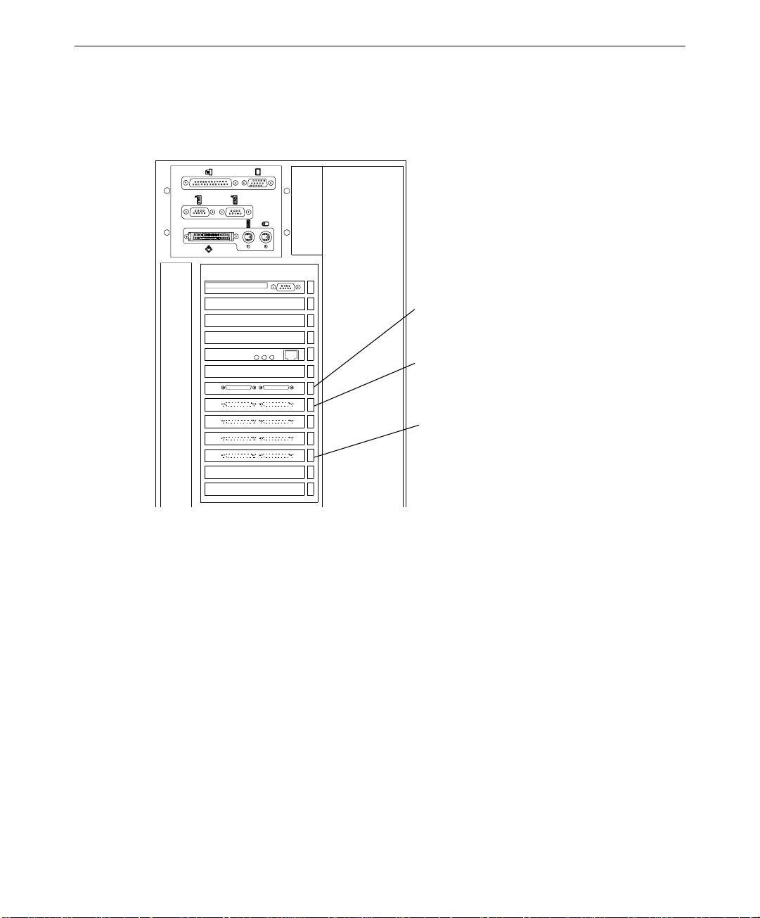
I/O Interface Board
The I/O interface board connects between the disk array’s bus and the MegaRAID controller
board via two 68-pin very high density (VHD) SCSI connectors. The connectors are labeled
Channel 0 and Channel 1.
Channel 0
Bus Configurations
The InterRAID-8e cabinet uses Ultra Wide SCSI cable configurations for single-bus or
dual-bus operation. Separate internal modules in the disk array cabinet define the bus
configuration.
u
The InterRAID-8e with the dual-bus module provides two separate channels for the
cabinet’s disk drive slots. The top or left cabinet slots connect to one of the channels,
and the bottom or right slots connect to the other channel.
u
The InterRAID-8e with the single-bus module provides one channel for the cabinet’s
disk drive slots.
I/O Interface
Board
Channel 1
Page 17

MegaRAID Controllers
The MegaRAID controller board that resides in the system base unit incorporates a 32-bit
RISC processor. The processor controls all functions including SCSI bus transfers, RAID
processing, configuration, data striping, error recovery, and drive building.
The MegaRAID controller features either two or three Ultra SCSI chips that provide the data
channels for connecting disk array cabinets. Each chip provides one channel. The use of the
channels depends on the cabinet’s bus configuration and the system base unit.
u
Dual-bus cabinets require two of the channels to be connected (Channel 0 and 1) to the
cabinet.
u
Single-bus cabinets use only one of the channels (Channel 0).
u
Some systems feature internal RAID, which uses one or two of the channels.
Chapters 2 and 3 provide additional information about connecting cabinets to the controller.
Applicable Intergraph Systems
3
The InterRAID-8e is available in deskside or rack-mount configurations for various systems.
The deskside cabinet is available as a dual-bus only. The rack-mount version is available as
dual-bus and single-bus, depending on the system to which it is attached. The following
table lists the InterRAID-8e cabinets and the applicable systems.
InterRAID-8e Cabinet
Deskside dual-bus InterServe 615, 625, 635, 645; InterServe 80;
Rack-mount dual-bus InterServe 615R, 625R; InterServe 8000; StudioZ
Rack-mount single-bus InterServe 615R, 625R; InterServe 8400
Intergraph System
InterServe 8000; TDZ-610
RAX
Returning Equipment to Intergraph Computer Systems
Some malfunctioning equipment cannot be repaired in the field, and you must return it to
Intergraph Computer Systems for repair. Follow the steps in the next sections to obtain a
Returned Goods Authorization (RGA) log number, complete the RGA form and shipping
label, and repackage the equipment.
Page 18

4
Obtain an RGA Log Number
The RGA log number must be included with the shipment for Intergraph Computer Systems
to properly track the repair work and return the equipment.
To obtain an RGA log number:
1. Determine the serial number of the system. The serial number is located on a white bar
code identification label on the back of the base unit.
2. Call the Customer Response Center at 1-800-633-7248, and identify your call to the
operator as a Warranty Call. Give the operator the serial number of the system, and you
will be given an RGA log number.
Complete the RGA Form and Shipping Label
The RGA form must accompany all returned equipment. When the service activity has been
completed by Intergraph Computer Systems, the repaired or replaced equipment will be
shipped to the address listed on the RGA form.
To complete the RGA form and shipping label:
1. Copy the RGA form at the back of this guide.
2. Complete the form, entering the RGA log number obtained from the Customer Response
Center. Ensure that the address in the From section is the location to which you want
the equipment to be returned.
3. Pack the equipment as described in this chapter.
4. Place the RGA form in the shipping box containing the equipment.
5. Copy the repair depot shipping labels at the back of this guide.
6. Add the RGA log number to a shipping label and affix it to the shipping box containing
the equipment.
7. Ship the box containing the equipment to Intergraph Computer Systems.
NOTE Parts damaged during shipping and parts not covered by the warranty are liable for repair
charges.
Repackage Disk Drives for Separate Shipment
If you need to return only the RAID disk drives, but not the disk array cabinet, they can be
returned separately. The disk drives cannot be returned in the box that shipped with the
cabinet. They must be returned in a specially designed multi-pack box for disk drive
shipment. The Intergraph multi-pack box provides the required protection needed when
shipping the disk drives by themselves.
Page 19

CAUTION Pack the RAID disk drives in the Intergraph multi-pack drive box for transportation. If the
drives are not packed into this box, they could be damaged during shipment.
If you do not have an Intergraph multi-pack box, call the Intergraph Order Desk at
1-800-543-1054.
Repackage Disk Drives and Cabinet
Use the original Intergraph packaging in which your equipment was shipped. The disk drive
box fits inside the shipping carton.
CAUTION Pack all equipment in the original boxes for transportation to avoid damage during shipment.
To repack the equipment:
1. Power down the disk array cabinet and wait for the RAID disk drives to completely stop
spinning. The disk drives could be damaged if removed while still spinning.
2. Remove all of the RAID disk drives from the cabinet. Handle the disk drives carefully
and by the edges only.
3. Place each disk drive into an antistatic bag and seal the bag.
5
4. Place one RAID disk drive into each compartment in the foam. If packing less than four
drives, place them in the foam to distribute the weight evenly. See the following figure.
rive Filler (for
1.0-inch high
rives only)
RAID Disk Drive (in antistat i c bag)
NOTE For 1.0-inch high drives, place a drive filler over each drive.
Top Foam Layer
Drive Foam
(holds up to four dr ives)
Drive Box
Page 20

6
5. Place the top foam layer into the drive box.
CAUTION If the top foam layer is not installed, the drives may move around inside the box causing
damage during shipment.
6. Securely tape the drive box closed.
CAUTION Remove all RAID disk drives from a disk array before repacking the cabinet. If you ship a
cabinet with disk drives installed, the drives and the cabinet could be damaged.
7. Place the bottom foam support into the disk array box, and then set the cabinet onto the
foam. See the following figure.
8. Place the top foam support onto the cabinet.
9. Securely tape the disk array box closed.
10. Place the disk array box into the shipping carton.
11. Place the filler at the end of the disk array box.
12. Place the two disk drive boxes alongside the disk array box.
13. Pack the cables and other miscellaneous parts into the accessories box.
14. Place the accessories box on top of the disk array box.
15. Ensure the RGA form is placed inside the shipping carton.
16. Securely tape the shipping carton.
Page 21

Accessories
Box
Filler
7
Top Foam Support
InterRAID-8e Cabinet
Bottom Foam Support
Disk Array Box
Shipping
Carton
The disk drive boxes were not designed to ship disk
drives by themselves. If shipping di sk dr ives alone,
order the Intergraph multi - pack box.
Disk Drive
Boxes
CAUTION The type of disk drive box that fits inside the shipping carton should be used only when
shipping drives with an InterRAID cabinet. Do not use it for shipping disk drives by
themselves or damage may occur.
Page 22

8
Page 23

2 Setting Up InterRAID-8e Deskside
This chapter describes setting up the deskside (standalone) InterRAID-8e cabinet. If setting
up a rack-mount InterRAID-8e cabinet, see Chapter 3. When setting up the deskside
cabinet, you will perform the following tasks:
u
Unpack the equipment.
u
Install the MegaRAID controller (if not pre-installed in the system base unit).
u
Set up the cabinet.
u
Connect the cables.
u
Install and label the RAID disk drives.
u
Power on and configure the system.
Carefully unpack the equipment. The shipping carton contains the following items:
u
MegaRAID controller board (if included)
u
InterRAID-8e cabinet (dual-bus only)
9
u
Disk drive boxes containing up to four drives
u
Diskettes containing configuration and utility software
u
Accessories box
The accessories box contains the following items:
u
InterRAID-8e cabinet power cord
u
Two RAID SCSI cables
u
Key for disk array cabinet
u
Disk drive labels
u
Drive Labeling instruction sheet
u
Power Supply Cord Selection instruction sheet
u
Antistatic Handling instruction sheet
Retain all packaging materials. Equipment returned for repair must be in the original
packaging to obtain warranty service, if provided under your contract agreement.
NOTE If any of the listed parts are missing or damaged, call the Customer Response Center at
1-800-633-7248.
Page 24

10
Installing the MegaRAID Controller
If the InterRAID-8e option includes a MegaRAID controller in the shipping carton, follow
these instructions to install the controller into the system. Otherwise, go to “Setting up the
Cabinet.” The following table shows information about the deskside systems that allow the
InterRAID-8e option.
System
Primary Controller Slot Secondary Controller Slots
TDZ-610 Not applicable Any available PCI
InterServe 6x5 with RAID PCI Slot 1 Any available PCI
InterServe 6x5 non-RAID Not applicable Any available PCI
InterServe 80 Not applicable Any available PCI
InterServe 8000 PCI Slot 4 PCI Slots 5 through 8
NOTE The systems with “Not applicable” for primary controller slot use a fixed disk drive as the boot
drive. All installed MegaRAID controllers are treated as secondary.
The following figure shows the three channel MegaRAID controller and Channels 0, 1, and
2. The two-channel version of the controller does not include the components for Channel 2.
Channel 0
Channel 0
(External)
Channel 1
(External)
Channel 1
Channel 2
NOTE For those systems using an internal channel for the internal RAID section, you cannot use the
external channel with the same number. For example, the InterServe 8000 uses Channel 0
and Channel 1 for the internal RAID section. Therefore, external Channel 0 and Channel 1 is
not available for connection.
Page 25

TDZ-610 and InterServe 6x5 Systems
The following figure shows the PCI slots of the TDZ-610 and the InterServe 6x5 systems.
PCI Slot 1 (Prim ary for
InterServe 6x5 with
PCI Slot 6
internal RAID)
11
To install the MegaRAID controller:
1. Ensure the system is powered off.
2. Open the base unit by removing the top cover, left side panel, and PCI access panel on
the bottom of the unit.
3. Remove the screw and blanking plate from an available PCI slot.
4. Install the MegaRAID controller. Press firmly and evenly over the PCI connector to
ensure the board seats completely into the slot.
5. Secure the board with the screw removed from the blanking plate.
6. Close the base unit.
7. Set up the disk array cabinet as described in “Setting up the Cabinet.”
Page 26

12
InterServe 80 Systems
The following shows the I/O panel on the back of the InterServe 80 systems.
PCI Slot 1
PCI Slot 7
To install the Two-channel MegaRAID controller:
1. Ensure the system is powered off.
2. Remove the top cover and left side panel from the system.
3. Remove the screw and blanking plate from an available PCI slot.
4. Install the MegaRAID controller. Press firmly and evenly over the PCI connector to
ensure the board seats completely into the slot.
5. Close the base unit.
6. Set up the disk array cabinet as described in “Setting up the Cabinet.”
Page 27
InterServe 8000 Systems
The following shows the I/O panel on the back of the InterServe 8000 systems.
13
PCI Slot 4
(Primary)
PCI Slot 5
PCI Slot 8
To install the MegaRAID controller:
1. Ensure the system is powered off.
2. Remove the right side panel from the system.
3. Remove the screw and blanking plate from an available PCI slot.
NOTE Install secondary controllers only in PCI slots 5 through 8. If you install secondary controllers
in PCI slots 1 through 3, the system will not boot.
4. Install the MegaRAID controller. Press firmly and evenly over the PCI connector to
ensure the board seats completely into the slot.
5. Close the base unit.
6. Set up the disk array cabinet as described in “Setting up the Cabinet.”
Page 28

14
Setting up the Cabinet
When setting up the deskside cabinet, stand the cabinet on its pre-installed metal foot near
the system base unit. The cabinets can be placed side-by-side. Keep the following in mind
when selecting a location.
u
Allow six inches of space in front of the cabinet for the door to open.
u
Allow at least a three-inch clearance in back of the cabinet for air circulation.
u
Place the cabinet on a hard, flat surface (not on carpet).
u
Ensure the surface will support the weight of the cabinets with all RAID disk drives
installed. A fully loaded deskside cabinet weighs approximately 70 pounds.
Connect the cables to the cabinet and to the controller as described next.
Connecting the Cables
This section describes connecting the RAID SCSI cables from the MegaRAID controllers to
the disk array cabinets. Information for choosing and connecting a power cord is also
included.
NOTE Keep track of the cabinet attached to each channel of the MegaRAID controllers. The drives
in each cabinet must be labeled according to their channel and controller as described later in
this chapter.
CAUTION The deskside InterRAID-8e can use RAID SCSI cables of only 1 meter. If you attach cables
longer than 1 meter to the cabinet, the cabinet and controller will not operate reliably.
CAUTION The disk array cabinets must not be daisy-chained to each other. If you attach cables in this
manner, the cabinet and controller may not operate reliably. Intergraph Computer Systems
does not recommend daisy-chaining cabinets.
Page 29
TDZ-610 and InterServe 6x5 Systems
Connect the RAID SCSI cables to the disk array cabinet and MegaRAID controller as
follows.
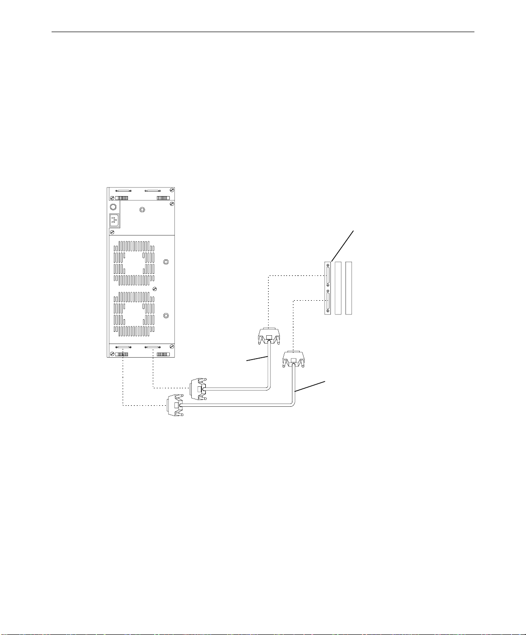
To connect the cables:
1. Connect a RAID SCSI cable to the Channel 0 port on the cabinet and to the Channel 0
port on the MegaRAID controller. Repeat for the Channel 1 port. See the following
figure.
15
MegaRAID Controller
External Ports on the
PCI I/O Panel
Channel 1
Channel 0
NOTE If necessary, the ports at the top of the deskside disk array cabinet can be used instead of the
lower ports.
2. Secure the cables using the thumb screws (finger tight only). Failure to secure the
cables properly can result in intermittent problems with the cabinet or the MegaRAID
controller.
3. Choose the proper power cord for the cabinet, depending on your country. See the
Power Supply Cord Selection instruction sheet included in the accessory pack.
4. Connect the power cord to the InterRAID-8e cabinet and to the facility power outlet, AC
distribution box, or uninterruptible power supply (UPS).
CAUTION If the system does not connect to a UPS, data loss can occur if there is a power failure.
Page 30

16
InterServe 80 Systems
Connect the RAID SCSI cables to the disk array cabinet and MegaRAID controller as
follows.
To connect the cables:
1. Connect a RAID SCSI cable to the Channel 0 port on the cabinet and to the Channel 0
port on the MegaRAID controller. Repeat for the Channel 1 port. See the following
figure.
MegaRAID Controller
External Ports on the
PCI I/O Panel
Channel 1
Channel 0
NOTE If necessary, the ports at the top of the deskside disk array cabinet can be used instead of the
lower ports.
2. Secure the cables using the thumb screws (finger tight only). Failure to secure the
cables properly can result in intermittent problems with the cabinet or the MegaRAID
controller.
3. Choose the proper power cord for the cabinet, depending on your country. See the
Power Supply Cord Selection instruction sheet included in the accessory pack.
4. Connect the power cord to the InterRAID-8e cabinet and to the facility power outlet, AC
distribution box, or uninterruptible power supply (UPS).
CAUTION If the system does not connect to a UPS, data loss can occur if there is a power failure.
Page 31

InterServe 8000 Systems
Connect the cables for the secondary controllers as follows.
NOTE Do not connect cables to the external ports of the primary controller, located in PCI Slot 4.
The primary controller uses Channel 0 and 1 for the internal RAID section, so a cable cannot
be connected to the external Channel 0 and Channel 1 port.
To connect the cables to the system and cabinet:
1. Connect a RAID SCSI cable to the Channel 0 port on the cabinet and to the Channel 0
port on the secondary MegaRAID controller. Repeat for the Channel 1 port. See the
following figure.
MegaRAID Controller
External Ports on the
PCI I/O Panel
17
Channel 0
Channel 1
NOTE If necessary, the ports at the top of the deskside disk array cabinet can be used instead of the
lower ports.
2. Secure the cables using the thumb screws (finger tight only). Failure to secure the
cables properly can result in intermittent problems with the cabinet or the MegaRAID
controller.
3. Choose the proper power cord for the cabinet, depending on your country. See the
Power Supply Cord Selection instruction sheet included in the accessory pack.
4. Connect the power cord to the InterRAID-8e cabinet and to the facility power outlet, AC
distribution box, or uninterruptible power supply (UPS).
CAUTION If the system does not connect to a UPS, data loss can occur if there is a power failure.
Page 32

18
Installing and Labeling RAID Disk Drives
The InterRAID-8e cabinet supports up to eight 1.0-inch or 1.6-inch high, 3.5-inch form
factor RAID disk drives. Capacities include 4 GB, 9 GB, and higher as the disk drives
become available. The slots of the InterRAID-8e cabinet are numbered from 1 to 8, starting
with the bottom slot. The drive SCSI ID’s of the InterRAID-8e cabinet by default are
numbered 0, 1, 2, 4, 5, 6, 8, and 9, starting with the bottom slot. The SCSI ID if SAF-TE
card by default is 3.
CAUTION High-capacity RAID disk drives are susceptible to physical shock. Handle all disk drives
carefully and avoid unnecessary handling.
To install and label the RAID disk drives:
1. Unlock the front panel door using the key for the InterRAID-8e cabinet.
2. Remove the RAID disk drives from the drive boxes.
CAUTION Carefully insert the disk drives to avoid damaging the connector.
3. Install the RAID disk drives into the cabinet as follows.
−
Extend the drive latching clips and slide the drive into the slot.
−
Push between the latching clips until the drive connects.
−
Close the drive latching clips until they snap into place, locking the drive into the
slot.
4. Label the installed drives as described below. Use the peel-off labels from the Drive
Labeling instruction sheet and fill in the information for each drive.
The left side of the disk drive label identifies the disk drive size (in GB). The label has
blank spaces for the numbers to indicate the MegaRAID controller board (ADP),
channel (CH), and SCSI ID (ID).
x GB
ADP
x GB
ADP
NOTE The label sheets do not include the numbers 3 and 7 for SCSI IDs. These ID numbers are
used by the disk array cabinet and the MegaRAID controller board.
CH ID
100
CH ID
Blank Disk Drive Label
Number Added
Page 33

The lower four RAID disk drives connect to one channel; the upper four RAID disk
drives connect to another channel. The following table shows the channel and ID
numbers used for drives installed in a cabinet.
19
Disk Drive Label
Cabinet Slots
ADP X CH 1 ID 4 8 (top)
ADP X CH 1 ID 2 7
ADP X CH 1 ID 1 6
ADP X CH 1 ID 0 5
ADP X CH 0 ID 4 4
ADP X CH 0 ID 2 3
ADP X CH 0 ID 1 2
ADP X CH 0 ID 0 1 (bottom)
5. If you have additional cabinets, install the disk drives and complete the drive label
information as appropriate.
Powering On and Configuring the System
To prevent accidental power off or on, the power switch is recessed and not accessible with
the door closed and locked. Before starting the system for the first time, read the following
important operating and software notices.
Important Operating Notices
u
In some instances, the audible alarm sounds when you power on the InterRAID-8e
cabinet. To silence the alarm, press the Menu and Enter keys on the Information
Control Panel. See Chapter 9, “InterRAID-8e Power Supply Failures,” for information
about alarm conditions.
u
Always power on the InterRAID-8e cabinet and wait for the audible beep before
powering on the system base unit.
u
If you turn off the power to the system base unit before completing the setup procedures,
you must reload the operating system. Once you power on the system base unit, do not
power off the system without completing Windows NT Server installation.
u
Always power off the system base unit before powering off the InterRAID-8e cabinet. If
you power off the cabinet first, the MegaRAID controller board will read the drives as
dead the next time you power on the system.
Page 34

20
Important Software Notices
u
You must complete the Windows NT Server installation before using the system.
Intergraph Computer Systems installs the MegaRAID BIOS configuration and Power
Console utilities on your system before shipment. Power Console provides valuable
information about the InterRAID-8e disk array, and can help you pinpoint any problems
that may occur in disk array operation. Power Console installation is described in
Appendix B of this guide, and in the hardware documentation delivered with your
server.
u
Intergraph Computer Systems recommends that you add a shortcut to Power Console to
the Windows NT Startup menu (Start/Programs/Startup). See Windows NT Help for
information on adding a shortcut to a menu on the Start menu.
u
The MegaRAID controller board has two types of write caching: write-through and
write-back. Write-through caching reduces the risk of data loss in the event of a power
failure. Write-back caching improves performance, but the drawback is potential data
loss if power fails. Intergraph Computer Systems recommends connection to a UPS to
guard against data loss.
u
Intergraph Computer Systems typically configures the MegaRAID controller board to
RAID level 5. MegaRAID controllers support RAID levels 0, 1, 3, 5, 10 (0+1), 30, and
50.
To power on and configure the system:
1. Power on the InterRAID-8e cabinet and wait for the audible beep. After the power-on
self-test completes, the Drive Status and Channel Mode LEDs remain green.
NOTE The Power Status LED remains amber and the LCD screen displays Non-Redundant Power
when only one power supply is present, or if more than four drives are used with two power
supplies.
2. Power on the system base unit and the monitor.
3. Configure the MegaRAID controllers installed in the system. The System Setup
contains basic information to configure the disk array appropriate for the system. See
Chapter 5, “Using the MegaRAID BIOS Configuration Utility” in this document for
details about specific procedures.
CAUTION After you configure the RAID disk drives, it is important that you backup the configuration to a
diskette. The diskette will be helpful in the event the configuration should become lost. See
the “Saving and Restoring a Configuration” section in Chapter 5.”
Use Disk Administrator in Windows NT to partition and format the disk space not used by
the operating system. When prompted to create a Signature File, select Yes. See the
Windows NT Server System Guide for information on using Disk Administrator.
Page 35

3 Setting Up InterRAID-8e Rack-Mount
This chapter describes setting up the rack-mount InterRAID-8e cabinet. If setting up a
deskside (standalone) InterRAID-8e cabinet, see Chapter 2. When setting up the rack-mount
cabinet, you will perform the following tasks:
u
Unpack the equipment.
u
Install the MegaRAID controller (if not pre-installed in the system base unit).
u
Install the cabinet in the rack.
u
Connect the cables.
u
Install and label the RAID disk drives.
u
Power on and configure the system.
Carefully unpack the equipment. The shipping carton contains the following items:
u
MegaRAID controller board (if included)
u
InterRAID-8e cabinet (single or dual-bus)
21
u
Disk drive boxes containing up to four drives
u
Diskettes containing configuration and utility software
u
Accessories box
The accessories box, included with the cabinet, contains the following items:
u
InterRAID-8e cabinet power cord
u
Handle brackets and screws
u
Rack mounting hardware (shelves, screws, and tinnerman nuts)
u
RAID SCSI cable (two cables, if dual-bus)
u
Key for disk array cabinet
u
Disk drive labels
u
Drive Labeling instruction sheet
u
Power Supply Cord Selection instruction sheet
u
Antistatic Handling instruction sheet
Retain all packaging materials. Equipment returned for repair must be in the original
packaging to obtain warranty service, if provided under your contract agreement.
Page 36

22
NOTE If any of the listed parts are missing or damaged, call the Customer Response Center at
1-800-633-7248.
Installing the MegaRAID Controller
If the InterRAID-8e option includes a MegaRAID controller in the shipping carton, follow
the instructions in this section to install the controller into the system. Otherwise, go to
“Installing the Cabinet into a Rack.” The following table shows information about the rackmount systems that allow the InterRAID-8e option.
System
Primary Controller Slot Secondary Controller Slots
TDZ-612 RAX Not applicable Any available PCI
RenderRAX Not applicable Any available PCI
InterServe 6x5R Not applicable Any available PCI
InterServe 8400,
PCI Slot 4 PCI Slots 5 through 8
InterServe 650/660
StudioZ RAX Not applicable PCI Slots 4 though 7
InterServe 8000 PCI slot 4 PCI slots 5 through 8
NOTE The systems with “Not applicable” for primary controller slot use a fixed disk drive as the boot
drive. All installed MegaRAID controllers are treated as secondary.
The following figure shows the MegaRAID controller and Channels 0, 1, and 2.
Channel 0
Channel 0
(External)
Channel 1
(External)
Channel 1
Channel 2
NOTE For those systems using an internal channel for the internal RAID section, you cannot use the
external channel with the same number. For example, the InterServe 8000 uses Channel 0
and Channel 1 for the internal RAID section. Therefore, external Channel 0 and Channel 1 is
not available for connection.
Page 37

TDZ-612 RAX, RenderRAX, and InterServe 6x5R Systems
PCI Slot 1
The following shows the I/O panel on the back of the TDZ-612 RAX, RenderRAX, and
InterServe 6x5R systems.
PCI Slot 6
To install the controller:
1. Ensure the system is powered off.
23
2. Remove the top cover.
3. Remove the screw and blanking plate from an available PCI slot.
4. Install the MegaRAID controller. Press firmly and evenly over the PCI connector to
ensure the board seats completely into the slot.
5. Secure the board with the screw removed from the blanking plate.
6. Replace the top cover.
7. Install the disk array cabinet as described in “Installing the Cabinet into a Rack.”
Page 38

24
InterServe 8400, InterServe 650/660, and StudioZ RAX Systems
The following shows the I/O panel on the back of the InterServe 8400, InterServe 650/660,
and StudioZ RAX systems.
PCI Slot 4
(Primary)
PCI Slot 8
(Secondary
PCI Slot 5
(Secondary)
To install the controller:
1. Ensure the system is powered off.
2. Remove the top cover from the system.
3. Remove the screw and blanking plate from an available PCI slot.
4. Install the MegaRAID controller. Press firmly and evenly over the PCI connector to
ensure the board seats completely into the slot.
5. Secure the board with the screw removed from the blanking plate.
6. If using the Channel 2 connector, see “InterServe 8400 Channel 2 Expansion” for
instructions to install and route the Channel 2 access cable.
NOTE Channel 2 expansion is not available for StudioZ RAX systems.
7. Replace the top cover.
8. Install the disk array cabinet as described in “Installing the Cabinet into a Rack.”
Page 39

InterServe 8000 Systems
The following shows the I/O panel on the back of the InterServe 8000 systems.
25
PCI Slot 4
(Primary)
PCI Slot 5
PCI Slot 8
To install the controller:
1. Ensure the system is powered off.
2. Remove the right side panel from the system.
3. Remove the screw and blanking plate from an available PCI slot.
NOTE Install secondary controllers only in PCI slots 5 through 8. If you install additional controllers
in PCI slots 1 through 3, the system will not boot.
4. Install the MegaRAID controller. Press firmly and evenly over the PCI connector to
ensure the board seats completely into the slot.
5. Secure the board with the screw removed from the blanking plate.
6. If using the Channel 2 connector, see “InterServe 8000 Channel 2 Expansion” for
instructions to install and route the Channel 2 access cable.
7. Replace the side panel.
8. Install the disk array cabinet as described in “Installing the Cabinet into a Rack.”
Page 40

26
InterServe 8400/650/660 Channel 2 Expansion
The MegaRAID controller has three channels available for cabinet connection. Two of the
channels (0 and 1) are available on the back of the controller. The third channel (2) is
accessible via the Channel 2 ports above the I/O panel. If the Channel 2 access cable is not
installed in the base unit, you must install the cable to use Channel 2 of the controller. To
determine if the cable is installed, see if the Channel 2 port has a connector or a metal plate
over the port. If a connector is present, the cable is installed. If the metal plate is present,
install the access cable if it is included with the disk array cabinet.
NOTE The disk array cabinet attached to the Channel 2 port must be a single-channel cabinet. The
following instructions describe how to install the Channel 2 access cables in the base unit.
These steps assume the required secondary controllers have been installed and the unit is
open.
To install the Channel 2 access cable:
1. Connect the Channel 2 access cables to the Channel 2 connector of the secondary
MegaRAID controllers.
2. Connect the other end of the access cables to the Channel 2 ports as follows. See the
following figure.
−
Attach the cable from the controller in PCI slot 5 to the right Channel 2 port.
−
Attach the cable from the controller in PCI slot 6 to the middle Channel 2 port.
−
Attach the cable from the controller in PCI slot 7 to the left Channel 2 port.
Channel 2 Access
Channel 2
Ports
PCI Slot 7
(Secondary)
Cabl e R outing
(Internal)
PCI Slot 5
(Secondary)
3. Close the base unit.
4. Install the disk array cabinet as described in “Installing the Cabinet into a Rack.”
Page 41

InterServe 8000 Channel 2 Expansion
PCI Slot 6
PCI Slot 7
PCI Slot 5
The MegaRAID controller has three channels available for cabinet connection. Two of the
channels (0 and 1) are available on the back of the controller. The third channel (2) is
accessible via the Channel 2 port to the left of the I/O panel. If the Channel 2 access cable is
not installed in the base unit, you must install the cable to use Channel 2 of the controller.
To determine if the cable is installed, see if the Channel 2 port has a connector or a metal
plate over the port. If a connector is present, the cable is installed. If the metal plate is
present, install the access cable if it is included with the disk array cabinet.
NOTE The disk array cabinet attached to the Channel 2 port must be a single-channel cabinet. The
following instructions describe how to install the Channel 2 access cables in the base unit.
These steps assume the required secondary controllers have been installed and the unit is
open.
To install the Channel 2 access cable:
1. Connect the Channel 2 access cables to the Channel 2 connector of the secondary
MegaRAID controllers.
2. Connect the other end of the access cables to the Channel 2 ports as follows. See the
following figure.
27
−
Attach the cable from the controller in PCI slot 5 to the top Channel 2 port.
−
Attach the cable from the controller in PCI slot 6 to the middle Channel 2 port.
−
Attach the cable from the controller in PCI slot 7 to the lower Channel 2 port.
Channel
2 Access
Cables
Channel
2 Ports
3. Close the base unit.
4. Install the disk array cabinet as described in “Installing the Cabinet into a Rack.”
Page 42

28
Installing the Cabinet into a Rack
The InterRAID-8e cabinet requires 4 U vertical mounting space. One U equals 1.75 inches.
The Intergraph rack is designed to support the weight of the cabinet when fully loaded with
disk drives (weighing approximately 70 pounds). If installing the cabinet into a nonIntergraph rack, ensure the rack can safety support the weight of the cabinet and drives.
To install the cabinet:
1. Attach the handle brackets to both sides of the InterRAID-8e cabinet. Use the eight
panhead screws (four for each bracket) supplied with the InterRAID-8e.
Handle Bracket
NOTE The sides of the InterRAID-8e cabinet have different hole patterns to match the pattern in
each handle bracket.
2. Determine the 4 U space (12 holes) in which to install the InterRAID-8e cabinet. The
following figure shows where the mounting shelf and tinnerman nut must be installed in
a given 4 U space.
Mounting Shelf
(End View)
4 U (12 Holes)
Tinnerman
Nut
Interior Face of
Mounting Post
Page 43
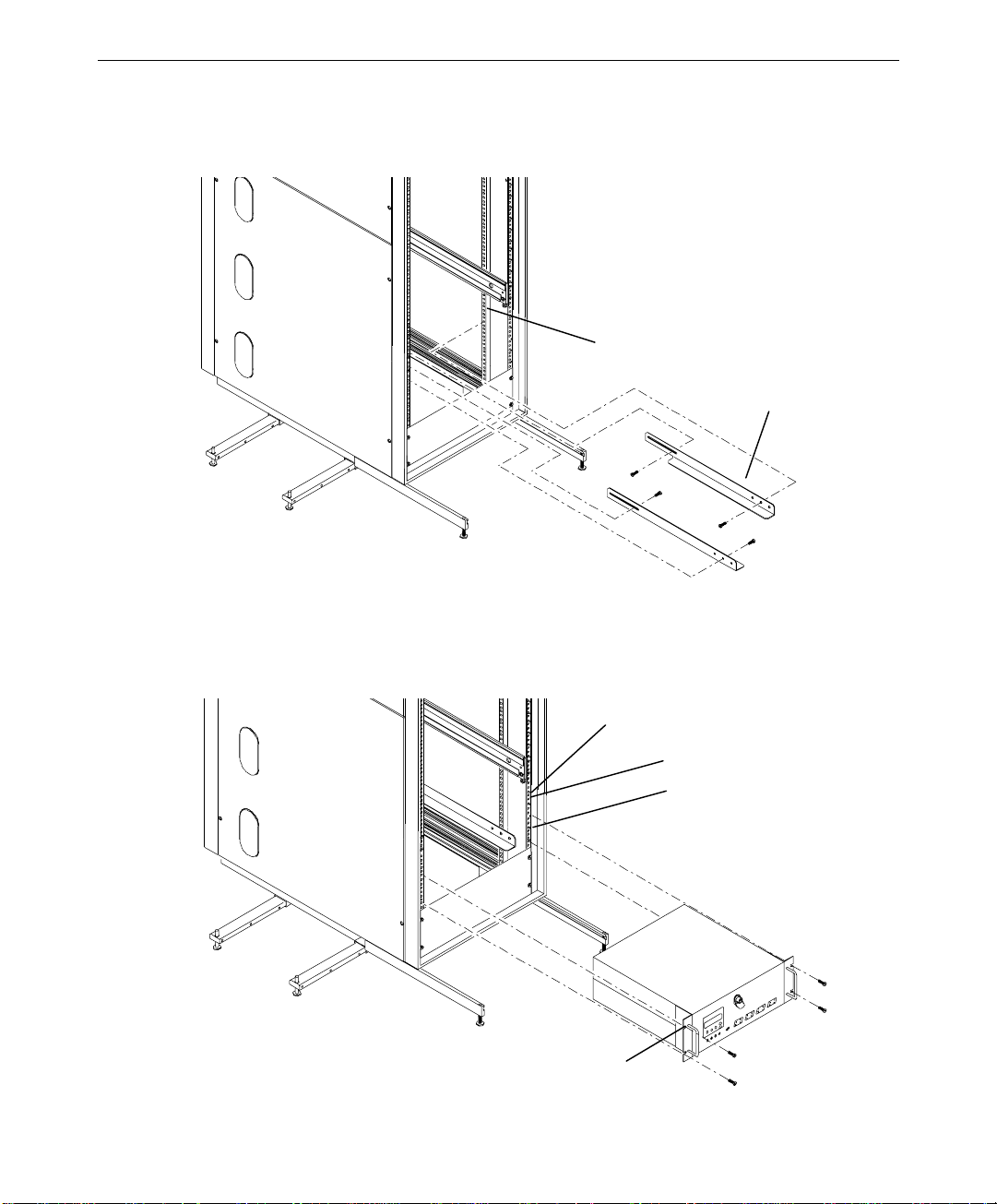
3. Using the screws provided, attach the mounting shelves to the rack. See the following
figure.
Interior Face of
Mounting Post
Mounting
Shelf
29
4. Place the InterRAID-8e cabinet on the mounting shelf as shown in the following figure.
5. Install tinnerman nuts on the exterior face of the two front mounting posts. Using the
screws provided, secure the handle brackets to the rack.
Exterior Face of
Mounting Post
Hole 22
Hole 15
Handle Bracket
Page 44

30
Connecting the Cables
This section describes the external RAID SCSI cable connections for single-bus and dual-bus
disk array cabinets. The single-bus cabinet uses only one channel from the MegaRAID
controller. The dual-bus cabinet uses two channels from the MegaRAID controller. The
following sections describe the details for connecting the cabinets.
NOTE Single-bus cabinets are not available for the StudioZ RAX systems.
CAUTION The rack-mount disk array cabinet can use RAID SCSI cables up to 2 meters. If you attach
cables longer than 2 meters to the cabinet, the cabinet and controller will not operate reliably.
Single-Bus Cabinets
Keep track of the cabinet attached to each channel of the MegaRAID controller. The drives
in each cabinet must be labeled according to their channel as described later in this chapter.
The channel usage and availability of the primary controller are as follows:
u
TDZ-612 RAX, RenderRAX, InterServe 6x5R -- These systems do not use a primary
controller.
u
InterServe 8400 -- Channels 0 and 1 are used for internal RAID section. Channels 0
and 1 are not available for connecting a cabinet.
u
InterServe 8000 -- Channels 0 and 1 are used for internal RAID section. Channels 0
and 1 are not available for connecting a cabinet.
The channels available on secondary controllers are as follows:
u
TDZ-612 RAX, RenderRAX, InterServe 6x5R -- Channels 0 and 1 are available for
connecting cabinets. Channel 2 is not available.
u
InterServe 8400, 8000 -- Channels 0 and 1 are available for connecting cabinets.
Channel 2 is available if the Channel 2 access cable is installed.
To connect RAID SCSI cables:
1. Connect the RAID SCSI cable to an available channel on the primary or secondary
MegaRAID controller. Connect the other end of the cable to the lower right connector
on the InterRAID-8e cabinet.
2. Secure the cables using the thumb screws (finger tight only). Failure to secure the
cables properly can result in intermittent problems with the cabinet or the MegaRAID
controller.
Page 45

Channel 2 Port
MegaRAID Controller
External Connect or s
NOTE Ensure that the 2 meter cables connect to the right side of the InterRAID cabinet. The
InterRAID-8e cabinet contains special extender circuitry that supports longer (2 meter) cable
lengths connected only on the right side of the cabinet. Do not connect 2 meter cables to the
left side of the cabinet.
31
NOTE The disk array cabinet attached to the Channel 2 port must be a single-bus cabinet.
3. Route the cables through the cable handler (if installed) or other retaining devices, such
as clips, cable ties, etc.
4. Choose the proper power cord for the cabinet, depending on your country. See the
Power Supply Cord Selection instruction sheet included in the accessory pack.
5. Connect the power cord to the InterRAID-8e cabinet and to the facility power outlet, AC
distribution box, or uninterruptible power supply (UPS).
CAUTION If the system does not connect to a UPS, data loss can occur if there is a power failure.
Dual-Bus Cabinets
Keep track of the cabinet attached to each channel of the MegaRAID controller. The drives
in each cabinet must be labeled according to their channel as described later in this chapter.
The cable connections from the primary controller differ for each system as described below.
The internal RAID section uses one or two channels of the primary controller, and those
channels are not available for attaching an external cable.
u
TDZ-612 RAX, RenderRAX, InterServe 6x5R -- These systems do not use a primary
controller.
Page 46

32
u
InterServe 8400 -- Channels 0 and 1 are used for internal RAID section. Channels 0
and 1 are not available for connecting RAID SCSI cables to one disk array cabinet.
u
InterServe 8000 -- Channels 0 and 1 are used for internal RAID section. Channels 0
and 1 are not available for connecting a cabinet.
The channels available on secondary controllers are as follows:
u
TDZ-612 RAX, RenderRAX, InterServe 6x5R -- Channels 0 and 1 are available for
connecting cabinets. Channel 2 is not available.
u
InterServe 8400, 8000 -- Channels 0 and 1 are available for connecting cabinets.
Channel 2 is available if the Channel 2 access cable is installed.
u
StudioZ RAX -- Channels 1 and 2 of the controller in PCI slot 4 are used for the internal
RAID section, and Channel 0 is not available. Controllers in PCI slot 5 through 7 use
Channels 0 and 1 to connect cabinets, and Channel 2 is not available.
To connect cables:
1. Connect the RAID SCSI cable Channel 0 on the primary or secondary MegaRAID
controller. Connect the other end of the cable to the Channel 0 connector on the
InterRAID-8e cabinet. Repeat for Channel 1.
2. Secure the cables using the thumb screws (finger tight only). Failure to secure the
cables properly can result in intermittent problems with the cabinet or the MegaRAID
controller.
The following figure shows connecting cables to Channel 0 and 1 of a controller.
Channel 0
Channel 1
NOTE Ensure that the 2 meter cables connect to the right side of the InterRAID cabinet. The
InterRAID-8e cabinet contains special extender circuitry that supports longer (2 meter) cable
lengths connected only on the right side of the cabinet. Do not connect 2 meter cables to the
left side of the cabinet.
MegaRAID Controller
External Connect ors
Page 47

3. Route the cables through the cable handler (if installed) or other retaining devices, such
as clips, cable ties, etc.
4. Choose the proper power cord for the cabinet depending on your country. See the Power
Supply Cord Selection instruction sheet included in the accessory pack.
5. Connect the power cord to the InterRAID-8e cabinet and to the facility power outlet, AC
distribution box, or uninterruptible power supply (UPS).
CAUTION If the system does not connect to a UPS, data loss can occur if there is a power failure.
Installing and Labeling RAID Disk Drives
The InterRAID-8e cabinet supports up to eight 1.0-inch or 1.6-inch high, 3.5-inch form
factor RAID disk drives. Capacities include 4 GB, 9 GB, and higher as the disk drives
become available. The slots of the InterRAID-8e cabinet are numbered from 1 to 8, starting
with the right slot.
CAUTION High-capacity RAID disk drives are susceptible to physical shock. Handle all disk drives
carefully and avoid unnecessary handling.
To install and label the RAID disk drives:
33
1. Unlock the front panel door using the key for the InterRAID-8e cabinet.
2. Remove the RAID disk drives from the drive boxes.
CAUTION Carefully insert the disk drives to avoid damaging the connector.
3. Install the RAID disk drives into the cabinet as follows.
−
Extend the drive latching clips and slide the drive into the slot.
−
Push between the latching clips until the drive connects.
−
Close the drive latching clips until they snap into place, locking the drive into the
slot.
4. Label the installed drives as described below. Use the peel-off labels from the Drive
Labeling instruction sheet and fill in the information for each drive.
The left side of the disk drive label identifies the disk drive size (in GB). The label has
blank spaces for the numbers to indicate the MegaRAID controller board (ADP),
channel (CH), and SCSI ID (ID).
Page 48

34
x GB
ADP
x GB
ADP
NOTE The label sheets do not include the numbers 3 and 7 for SCSI IDs. These ID numbers are
used by the disk array and for the MegaRAID controller board.
In a single-bus InterRAID-8e cabinet, all eight RAID disk drives connect to a single
channel. Use the following table to label the drives:
Disk Drive Label
ADP X CH X ID 9 8 (left)
ADP X CH X ID 8 7
ADP X CH X ID 6 6
ADP X CH X ID 5 5
ADP X CH X ID 4 4
ADP X CH X ID 2 3
ADP X CH X ID 1 2
ADP X CH X ID 0 1 (right)
In a dual-bus InterRAID-8e cabinet, the right four RAID disk drives connect to one
channel and the left four RAID disk drives connect to another channel. The following
table shows the channel and ID numbers used for drives installed in a cabinet.
CH ID
100
CH ID
Cabinet Slots
Blank Disk Drive Label
Number Added
Disk Drive Label
ADP X CH 1 ID 4 8 (left)
ADP X CH 1 ID 2 7
ADP X CH 1 ID 1 6
ADP X CH 1 ID 0 5
ADP X CH 0 ID 4 4
ADP X CH 0 ID 2 3
ADP X CH 0 ID 1 2
ADP X CH 0 ID 0 1 (right)
5. If you have additional cabinets, install the disk drives and complete the drive label
information as appropriate.
6. See the StudioZ RAX System Setup for specific information about drive labeling.
Cabinet Slots
Page 49

Powering On and Configuring the System
To prevent accidental power off or on, the power switch is recessed and not accessible with
the door closed and locked. Before starting the system for the first time, read the following
important operating and software notices.
Important Operating Notices
u
In some instances, the audible alarm sounds when you power on the InterRAID-8e
cabinet. To silence the alarm, press the Menu and Enter keys of the Information
Control Panel. See Chapter 9, “InterRAID-8e Power Supply Failures,” for information
about alarm conditions.
u
Always power on the InterRAID-8e cabinet and wait for the audible beep before
powering on the system base unit.
u
If you turn off the power to the system base unit before completing the setup procedures,
you must reload the operating system. Once you power on the system base unit, do not
power off the system without completing Windows NT Server installation.
u
Always power off the system base unit before powering off the InterRAID-8e cabinet. If
you power off the cabinet first, the MegaRAID controller board will read the drives as
dead the next time you power on the system.
35
Important Software Notices
u
You must complete the Windows NT Server installation before using the system.
Intergraph Computer Systems installs the MegaRAID BIOS configuration and Power
Console utilities on your system before shipment. Power Console provides valuable
information about the InterRAID-8e disk array, and can help you pinpoint any problems
that may occur in disk array operation. Power Console installation is described in
Appendix B of this guide, and in the hardware documentation delivered with your
server.
u
Intergraph Computer Systems recommends that you add a shortcut to Power Console to
the Windows NT Startup menu (Start/Programs/Startup). See Windows NT Help for
information on adding a shortcut to a menu on the Start menu.
u
The MegaRAID controller board has two types of write caching: write-through and
write-back. Write-through caching reduces the risk of data loss in the event of a power
failure. Write-back caching improves performance, but the drawback is potential data
loss if power fails. Intergraph Computer Systems recommends connection to a UPS to
guard against data loss.
u
Intergraph Computer Systems typically configures the MegaRAID controller board to
RAID level 5. MegaRAID controllers support RAID levels 0, 1, 3, 5, 10 (0+1), 30, and
50.
Page 50

36
To power on and configure the system:
1. Power on the InterRAID-8e cabinet and wait for the audible beep. After the power-on
self-test completes, the Drive Status and Channel Mode LEDs remain green.
NOTE The Power Status LED remains amber and the LCD screen displays Non-Redundant Power
when only one power supply is present, or if more than four drives are used with two power
supplies.
2. Power on the system base unit and the monitor.
3. Configure the MegaRAID controllers installed in the system. The System Setup
contains basic information to configure the disk array appropriate for the system. See
Chapter 5, “Using the MegaRAID BIOS Configuration Utility” in this document for
details about specific procedures.
CAUTION After you configure the RAID disk drives, it is important that you backup the configuration to a
diskette. The diskette will be helpful in the event the configuration should become lost. See
the “Saving and Restoring a Configuration” section in Chapter 5.”
4. Use Disk Administrator in Windows NT to partition and format the disk space not used
by the operating system. When prompted to create a Signature File, select Yes. See the
Windows NT Server System Guide for information on using Disk Administrator.
Page 51

4 Using the Information Control Panel
You can use the Information Control Panel (ICP) to silence the audible alarm, and monitor
the power supplies, fans, microprocessor, and cabinet temperature. Other menu functions let
you view component system status, read the firmware revision level, and establish a passcode
to protect SCSI ID options.
The liquid crystal display provides a four line by twenty character display. Of the five
function keys, two move the Menu Selector up or down. The
or returns to the main menu,
ESCAPE backs up one level or cancels an action.
ENTER selects the option indicated by the Menu Selector, and
MENU key selects menu options
37
Menu Selector
System Status Icon
Main Menu
Appears when
more options
are available
above
Appears when
more options
are available
below
Function
Keys
MENU ENTER ESCAPE
To display the Main menu, press the MENU key. Use the up and down arrow keys to make
your selection, and then press the
cursor to TURN OFF ALARM and press the
ENTER key. For example, to silence the alarm, move the
ENTER key.
Page 52

38
System Status Icon
An animated System Status icon appears in the ICP approximately 30 seconds after a static
display and indicates system status. It displays a “happy face” and looks left and right when
all systems operate normally. If an abnormality occurs within the system, the icon changes
to a “sad face” requesting your attention.
Systems Systems
Normal Abnormal
Hardware Menu
The Hardware menu displays the following options:
u
Component Status
u
Configuration Info
u
POST Results
u
Internal Temp
Component Status
This option gives a list and current status of the power supplies and fans installed in the
InterRAID-8e cabinet. The following is an example display:
PWR SPLY 1...OK
PWR SPLY 2...OK
PWR SPLY 3...MISSING
FAN 1........FAILED
FAN 2........OK
FAN SPEED....93%
BUS CONFIG...SINGLE
If an error occurs during startup, the alarm sounds a continuous tone. You can display the
Component Status menu to verify a suspected failed component. Component status is
indicated by OK, Missing, or Failed. If you receive a hardware error, display the ICP Main
menu and choose Hardware menu, then select Component Status and use the up or down
arrow keys to view a complete list of the components.
Page 53

During normal operation, if one of the power supplies fails, a continuous alarm sounds and a
warning message displays. The message tells you that the state of the power supply system is
no longer redundant. Display the Component Status menu to determine which power supply
has failed. Identify the failed unit by the power supply LED. Replace the failed power
supply to return the system to a redundant state.
Configuration Info
This option displays the cabinet type (SAF-TE) for the InterRAID-8e cabinet, and displays
information about the current RAID firmware, including product name, slot assignment,
RAM version, ROM version, and ID (in Hex format). The SAF-TE controller executes
RAM and ROM firmware code to monitor the cabinet. The following is an example display:
PROD: InterRAID-8e SAF-TE
SLOT 1 CARD:
I/O INTERFACE
RAM REVISION: 0.xx
ROM REVISION: 1.xx
ID: 64363264h
POST Results
39
This option displays the diagnostics performed during the startup power-on self-test (POST).
If an error occurs it displays in the ICP, LEDs blink, and the alarm sounds. The following is
an example display:
ROM CHKSUM OK
RAM CHKSUM OK
RAM R/W OK
SCSI BUS 0 OK
SCSI BUS 1 OK
PROCESSOR OK
Internal Temp
This option displays the current internal cabinet temperature using the highest indication of
two sensors. Cabinet temperature is measured within the drive bay area between drive slots
2 and 3, and between slots 7 and 8. By sensing cabinet temperature in these locations, the
system provides maximum protection. The temperature displays in both Fahrenheit and
Celsius degrees. The following is an example display:
CABINET INTERNAL
TEMPERATURE
96° F/36° C
Page 54

40
Options Menu
The Options Menu displays the following selections.
u
SCSI ID
u
Heat Threshold
u
SAF-TE Chain ID
u
Change Passcode
u
Lock (or Unlock)
SCSI ID
SCSI ID displays the ID that is set for each disk drive slot. Intergraph Computer Systems
recommends that you do not change any SCSI ID settings, even though SCSI IDs 0 through
15 are available and can be changed at the SCSI ID menu. If you change a SCSI ID setting,
you must turn off power to the InterRAID-8e cabinet and wait 30 seconds before turning on
power again for those settings to take effect. Be sure to turn off the power to the system base
unit before you turn off power to the InterRAID-8e cabinet.
NOTE If you turn off the power to the InterRAID-8e cabinet and then power off the system base unit,
the RAID controller will mark offline all drives in the array.
Set Upper and Lower Slot IDs
NOTE Disk drive SCSI IDs cannot be set individually with these menu selections.
Intergraph Computer Systems recommends that you do not change the SCSI ID settings. If
necessary, you can set SCSI IDs manually for each group of slots from a pre-defined table of
IDs. The currently set IDs will display on the ICP. Refer to the following example:
0123
Lower 4 0124
4567
4568
5678
The IDs will be assigned sequentially beginning with the lowest slot in the group. Choose
“Set Lower Slot IDs” or “Set Upper Slot IDs” for the appropriate slots and press the ENTER
key.
Page 55

41
Reset Default IDs
Choosing the Reset Default IDs option from the SCSI ID menu will automatically set the
SCSI IDs to IDs 0, 1, 2, and 4 for the disk drives, and ID 3 for the SAF-TE. SCSI IDs for
the drives will be the same for both SCSI bus channels.
NOTE ID 3 is normally reserved for the InterRAID-8e SAF-TE board. The SAF-TE board contains
the control and monitoring electronics for the disk array. The SAF-TE board resides in one of
the two slots located in the top bay of the InterRAID-8e cabinet. The SAF-TE board ID uses
“OB” to indicate Off Bus (off line) mode. However, if SAF-TE is off line, the LEDs and other
error reporting signals will not function properly.
Heat Threshold
NOTE The Heat Threshold value is pre-set at the factory and should not be changed unless directed
by Intergraph Computer Systems Technical Support. The default setting is 116 degrees F
(47 degrees C).
Choose this option to change the temperature value for the temperature monitoring system.
If the temperature exceeds the set value, a Temperature Threshold Exceeded message
displays in the ICP. The RAID cabinet alarm sounds continuously until the problem is
corrected.
SAF-TE Chain ID
This option is for configuring the SAF-TE board for master and slave modes when cabinets
are daisy chained. Intergraph does not recommend daisy chaining InterRAID-8e cabinets.
The default setting for SAF-TE Chain ID is None.
Change Passcode
NOTE Lock mode is disabled until a passcode is entered. To enable lock mode, enter the default
passcode.
This option allows an administrator to create or change a passcode to protect access to the
SCSI ID menu, Heat Threshold, Change Passcode, and Lock (or Unlock) features.
Use the arrow keys to change the code value (0-9) and the
to the next. Then press the
prompted to press the
ENTER key after you have made your selections. You are
ESCAPE key after the passcode is changed for the change to take affect.
The new passcode does not take affect until you have returned to the ICP main menu and
“Status OK” displays.
NOTE If you lose your passcode, call the Customer Response Center at 1-800-633-7248 and ask
that your call be directed to the Solutions Center.
ENTER key to move from one field
Page 56
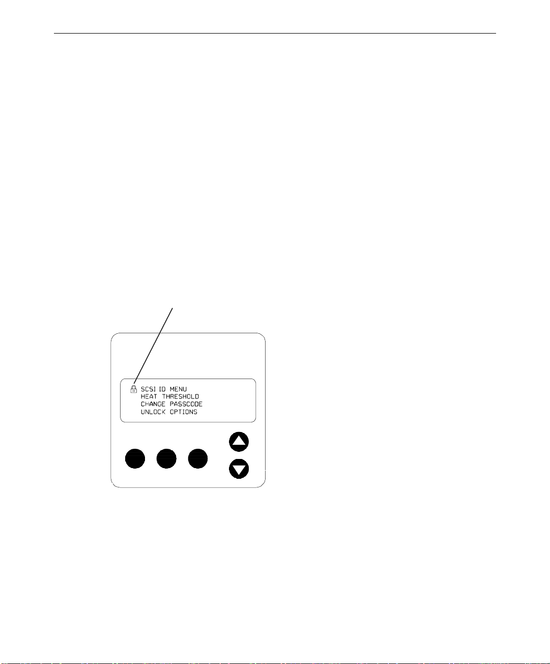
42
Lock (or Unlock)
This option lets you lock or unlock the Heat Threshold and Change Passcode items found
under the Options Menu. The option lets you change and lock the values to protect them
from being changed by unauthorized users.
The following is an example display:
ENTER 4 DIGIT
PASSCODE
▼
0000
Select Lock Options from the Options menu. Use the arrow keys to change the code value
(0-9) and the
you have made your selections. A lock icon appears in the ICP while the options remain
locked, as shown in the following example. You will be prompted that the SCSI ID Menu
options are locked until you have cycled the menus back to the ICP main menu and “Status
OK” displays.
ENTER key to move from one field to the next. Then press the ENTER key after
Lock Icon
MENU ENTER ESCAPE
Page 57

5 Using the MegaRAID BIOS
Configuration Utility
This chapter describes how to use the MegaRAID BIOS Configuration Utility (hereafter
referred to as MegaRAID BIOS) to configure disk arrays and logical drives. This utility is
executed instead of booting the operating system. Refer to Appendix B, “Software Updates”
for installing the MegaRAID BIOS configuration utility.
The topics in this chapter include the following:
u
Identifying controller assignments
u
Starting MegaRAID BIOS
u
Identifying Management menu options
u
Exiting MegaRAID BIOS
u
Management menu tree
u
Configuring arrays and logical drives
43
u
Rebuilding critical logical drives
u
Using a pre-loaded SCSI drive “as-is”
u
Saving and restoring a configuration
NOTE If you need to load the new driver, follow the applicable instructions in Appendix B, “Software
Updates.”
Identifying Controller Assignments
CAUTION The number assigned to the controller changes according to the number of installed
controllers. Note that MegaRAID BIOS refers to controllers as “Adapters.”
MegaRAID BIOS detects the presence of RAID controllers and assigns the controller
numbers in a unique way. The assignments also vary depending on the system boot device.
Fixed Hard Disk Drive
Intergraph systems that include a MegaRAID controller but use a fixed disk drive on a
separate controller as a boot device are covered in this section.
Page 58

44
The following tables show how MegaRAID BIOS lists from one to five installed controllers.
One Controller PCI Slot
1 First 0
Two Controllers PCI Slot
1 First 1
2 Second 0
Three Controllers PCI Slot
1 First 2
2 Second 1
3 Third 0
Four Controllers PCI Slot
1 First 3
2 Second 2
3 Third 1
4 Fourth 0
Five Controllers PCI Slot
1 First 3
2 Second 2
3 Third 1
4 Fourth 0
5 Fifth 4
Controller BIOS Configuration
Controller BIOS Configuration
Controller BIOS Configuration
Controller BIOS Configuration
Controller BIOS Configuration
InterServe 615, 625, 635, 645 Systems
InterServe 615, 625, 635, 645 systems are shipped from Intergraph Computer Systems with
RAID controllers installed in PCI slots 1 through 5 which should remain in these slots. On a
system with multiple RAID controllers, always use the RAID controller in PCI slot 1 as the
boot controller. On a system with one RAID controller, the controller resides in PCI slot 1.
The following tables show how MegaRAID BIOS lists the installed controllers.
One Controller PCI Slot
1 First 0 (Boot)
Controller BIOS Configuration
Page 59

Two Controllers PCI Slot Controller BIOS Configuration
1 First 0 (Boot)
2 Second 1
45
Three Controllers PCI Slot
1 First 0 (Boot)
2 Second 2
3 Third 1
Four Controllers PCI Slot
1 First 0 (Boot)
2 Second 3
3 Third 2
4 Fourth 1
Five Controllers PCI Slot
1 First 0 (Boot)
2 Second 3
3 Third 2
4 Fourth 1
5 Fifth 4
InterServe 8400 Systems
Controller BIOS Configuration
Controller BIOS Configuration
Controller BIOS Configuration
InterServe 8400 systems are shipped from Intergraph Computer Systems with RAID
controllers installed in PCI slots 4 through 8 which should remain in these slots. On a
system with multiple RAID controllers, always use the RAID controller in PCI slot 4 as the
boot controller. On a system with one RAID controller, the controller resides in PCI slot 4.
The following tables show how MegaRAID BIOS lists the installed controllers.
One Controller PCI Slot
4 First 0 (Boot)
Two Controllers PCI Slot
4 First 0 (Boot)
5 Second 1
Controller BIOS Configuration
Controller BIOS Configuration
Page 60

46
Three Controllers PCI Slot Controller BIOS Configuration
4 First 0 (Boot)
5 Second 2
6 Third 1
Four Controllers PCI Slot
4 First 0 (Boot)
5 Second 3
6 Third 2
7 Fourth 1
Five Controllers PCI Slot
4 First 0 (Boot)
5 Second 3
6 Third 2
7 Fourth 1
8 Fifth 4
InterServe 8000 Systems
InterServe 8000 systems are shipped from Intergraph Computer Systems with RAID
controllers installed in PCI slots 4 through 8 which should remain in these slots. On a
system with multiple RAID controllers, always use the RAID controller in PCI slot 4 as the
boot controller. On a system with one RAID controller, the controller resides in PCI slot 4.
The following tables show how MegaRAID BIOS lists the installed controllers.
Controller BIOS Configuration
Controller BIOS Configuration
One Controller PCI Slot
4 First 0 (Boot)
Two Controllers PCI Slot
4 First 0 (Boot)
5 Second 1
Controller BIOS Configuration
Controller BIOS Configuration
Page 61

Three Controllers PCI Slot Controller BIOS Configuration
4 First 0 (Boot)
5 Second 1
6 Third 2
47
Four Controllers PCI Slot
4 First 0 (Boot)
5 Second 1
6 Third 2
7 Fourth 3
Five Controllers PCI Slot
4 First 0 (Boot)
5 Second 1
6 Third 2
7 Fourth 3
8 Fifth 4
Starting MegaRAID BIOS
When the system boots, press CTRL+M when the following appears:
MEGARAID CONTROLLER BIOS Version
Host Adapter-1 Firmware Version
0 Logical Drives found on the Host Adapter
0 Logical Drives handled by BIOS
Press <Ctrl><M> to run MegaRAID BIOS Configuration Utility
Controller BIOS Configuration
Controller BIOS Configuration
x.xx
Aug 1, 1996
x.xx
DRAM Size 8 MB
NOTE If you do not press CTRL+M within a few seconds of the prompt, the system continues the
normal boot procedure.
For each MegaRAID controller in the system, the firmware version, DRAM size, and the
status of logical drives on that controller displays. When you press
Management menu displays.
CTRL+M, the
Page 62

48
Identifying Management Menu Options
The Management menu options are as follows:
Option
Configure Configures physical arrays and logical drives
Initialize Initializes one or more logical drives
Objects Individually accesses controllers, logical drives, physical drives and
Format Low-level formats a hard disk drive
Rebuild Rebuilds a failed disk drive
Check
Consistency
Select Adapter Selects a MegaRAID host adapter (controller)
Disable BIOS Disables the BIOS
The following table defines some terms you will see while configuring drives and running
the MegaRAID BIOS configuration utility.
READY Disk drive ready for configuration
ONLINE Disk drive ready for use
REBUILD Disk drive in rebuild state
OFFLINE Unformatted drive
PACK Configured pack
DRIVES Number of drives in a pack
SIZE Size of the packs (in megabytes)
HOTSP Disk drive configured as hotspare (standby) drive
FAIL Disk drive in fail state
Description
SCSI channel settings
Verifies that the redundancy data is correct in logical drives using
RAID level 1, 3, or 5
Exiting MegaRAID BIOS
To exit the MegaRAID BIOS configuration utility, press ESC while the Management menu
displays. Choose Yes at the prompt to save changes and exit. You must then reboot the
system. The MegaRAID BIOS message displays again. Press
Configuration Utility prompt displays.
ESC when the BIOS
Page 63

Management Menu Tree
The following is an expansion of the Management menu options. The menu items are
explained on the following pages.
CONFIG U RE -- Easy Co nf ig u rati o n
New Configuration
View/Add /Delete Configuration
Clear Configuration
INITIALIZ E -OBJECTS -- Adapte r -- Cl e ar Co nf iguration
Logical Drive -- Initialize
Physical Drive -- Rebuild
SCSI Channel/ Terminate High 8 Bits
Channel s (0, 1, 2) -- Termin ate Wi d e Chann el
FORMA T -REBU I LD -CHECK CONSISTENCY -SELECT ADAPTER -DISABLE BIOS --
49
Fle xRAID Po werFail
Flexible Dyna mic Si zing
Disk Spin-up Timings
Chi p Se t Ty pe
Cache Flush Timing s
Rebu i ld Rat e
Alarm Control
Auto Rebuild
Che ck Co n si s te nc y
View/Update Parameters
Format
Make Online
Fail Drive
Make Hotspare
View Drive Information
Synchronous Negotiation
SCSI- 2 Co m mand Tag gi ng
Disable Termination
Set Pow e rOn De faul ts
Ult ra SC SI
Page 64

50
Configure Menu
Choose the Configure option from the Management menu to select a method for configuring
arrays and logical drives. Intergraph Computer Systems recommends that you view a
configuration to prevent accidental modification of data.
Option
Easy
Configuration
New
Configuration
View/Add/Delete
Configuration
Clear
Configuration
Description
Select this option to perform a basic logical drive configuration where
every physical array you define is automatically associated with exactly
one logical drive.
Select this option to discard the existing configuration information and
to configure new arrays and logical drives. In addition to providing the
basic logical drive configuration functions, New Configuration allows
you to associate logical drives with multiple or partial arrays.
Select this option to examine the existing configuration and/or to specify
additional arrays and logical drives. View/Add/Delete Configuration
provides the same functions available in New Configuration.
Select this option to erase the current configuration information from the
MegaRAID controller non-volatile memory.
Initialize Menu
Choose Initialize from the Management menu to initialize one or more logical drives.
Initializing typically follows configuring a new logical drive.
CAUTION Initializing a logical drive destroys all data on the logical drive.
Objects Menu
Choose Objects from the Management menu to access the controllers (adapters), logical
drives, physical drives, SCSI channels, and Battery Backup options individually. You can
also change certain settings for each object. The Objects menu displays as follows.
-------------- Objects ---------------Adapter
Logical Drive
Physical Drive
SCSI Channel
Battery Backup
Page 65

51
Ensure the following important default settings of the Objects menu:
u
Under Objects/Adapter/Chip Set Type, ensure “Others” is selected.
u
Under Objects/Adapter/Alarm Control, ensure “Disable” is selected.
u
Under Objects/Adapter/Spinup Timings/Spinup Parameters, ensure “two drives every
six seconds” is selected.
u
Under Objects/SCSI Channel/Ultra SCSI, ensure “Enable” is selected for channels
connected to InterRAID-8e cabinets only.
u
After a logical drive is configured, Under Objects/Logical Drive/Drive #/View-Update
Parameters/FlexRAID Virtual Sizing, ensure “Disable” is selected.
Adapter
If your system has more than one MegaRAID controller, choose the Adapter option from the
Objects menu to select a MegaRAID controller and to modify the parameters. The following
displays:
x
-------------- Adapter
---------------Clear Configuration
FlexRAID PowerFail = DISABLED
Disk Spin-up Timings
Chip Set Type
Cache Flush Timings
Rebuild Rate
Alarm Control
Auto Rebuild = ENABLED
The following table describes the Adapter menu options.
Option
Clear
Configuration
FlexRAID
PowerFail
Disk Spin-up
Timings
Description
Choose this option to erase the current configuration from the controller
non-volatile memory.
Choose this option if you have battery backup installed. Default is
disabled.
Choose this option to set the method and timing for spinning up the hard
disk drives in the system. Default is 2 every 6 seconds.
Chip Set Type Choose this option to program the MegaRAID controller for a specific
motherboard chip set type, such as Intel Neptune, Intel Saturn, or other
chip set. Default is other.
Cache Flush
Timings
Choose this option to set the cache flush interval to once every 2, 4, 6, 8,
or 10 seconds. Default is 2.
Page 66

52
Option Description
Rebuild Rate Choose this option to change the rebuild rate for the controller. You can
also display the firmware version number.
Alarm Control Choose this option to enable, disable, or silence the onboard alarm tone
generator. Default is disable.
Auto Rebuild Choose this option to enable automatic rebuild. Default is enabled.
Logical
Drive
Choose the Logical Drive option from the Objects menu to select a logical drive and to
perform the listed actions.
The following table describes the Logical Drives options.
Option
Description
Initialize Choose this option to initialize the selected logical drive. This should be
done for every logical drive you configure.
Check
Consistency
Choose this option to verify the correctness of the redundancy data in the
selected logical drive. This option is only available if RAID level 1, 3, or
5 is used.
View/Update
Parameters
Choose this option to display the properties of the selected logical drive;
you can modify the cache write policy, read policy, I/O policy, and
FlexRAID Virtual Sizing from this menu.
Page 67

Physical Drive
Choose the Physical Drive option from the Objects menu to select a physical device and to
perform the operations listed in the table below. The physical hard disk drives in the system
are listed. Move the cursor to the desired device and press
NOTE On systems with two-channel MegaRAID controllers, only two columns representing the two
channels will appear on the Physical Drive menu.
ENTER to display the following:
53
The following table describes the Physical Drive options.
Option
Description
Rebuild Choose this option to rebuild the selected disk drive.
Format Choose this option to low-level format the selected disk drive.
Make Online Choose this option to change the state of the selected disk drive to Online.
Fail Drive Choose this option to change the state of the selected disk drive to Fail.
Make Hotspare Choose this option to designate the selected disk drive as a hotspare.
View Drive
Information
Synchronous
Negotiation
SCSI-2
Command
Choose this option to display the manufacturer data for the selected
physical device.
Choose this option to enable or disable synchronous negotiation for the
selected physical device. The default is Enabled.
Choose this option to set the number of queue tags per command to 2, 3,
or 4, or to disable command tagging. The default setting is 4 queue tags.
Tagging
SCSI Channel
Choose the SCSI Channel option from the Objects menu to select a SCSI channel on the
currently selected controller.
Page 68

54
The following displays:
-------------- Channel
x
---------------Terminate High 8 Bits
Terminate Wide Channel
Disable Termination
Set PowerOn Defaults
Ultra SCSI = DISABLED
The following table describes the SCSI Channel options.
Option
Terminate
High 8 Bits
Description
Choose this option to enable termination on the selected channel for the
upper eight bits and disable termination on the MegaRAID controller for
the lower eight bits. This setting is required if the selected SCSI channel
is terminated with 8-bit devices at both ends.
Terminate
Wide Channel
Choose this option to enable wide channel termination for the selected
channel. This is required if the MegaRAID controller is at one end of the
SCSI bus for the selected channel.
Disable
Termination
Choose this option to disable termination on the MegaRAID controller for
the selected channel. This option should be used if the selected SCSI
channel is terminated with Wide devices at both ends.
Set PowerOn
Defaults
Choose this option to have the MegaRAID controller examine its SCSI
channels and to set its termination automatically.
Ultra SCSI Choose this option to enable or disable Ultra SCSI. Default is disabled.
Format Menu
Choose Format from the Management menu to low-level format one or more physical drives.
WARNING Formatting a hard drive destroys all data on the drive.
Since most SCSI disk drives are low-level formatted at the factory, this step is usually not
necessary. You must format a disk only if one of the following applies:
u
The disk drive was not low-level formatted at the factory.
u
There are an excessive number of media errors detected on the disk drive.
You do not need to use the Format option to erase existing information on your SCSI disks,
such as a DOS partition. That information is erased when you initialize the logical drive(s).
Page 69

Rebuild Menu
Choose Rebuild from the Management menu to rebuild one or more failed disk drives.
Check Consistency Menu
Choose this option from the Management menu to verify the redundancy data in logical
drives using RAID levels 1, 3, or 5.
CAUTION Checking consistency could mean loss or corruption of data when an inconsistency is found
and corrected.
When you choose Check Consistency, the parameters of the existing logical drives on the
current controller and a selection menu listing the logical drives by number appear.
55
Press the arrow keys to highlight the desired logical drives. Press the spacebar to select or
deselect a drive for consistency checking. Press
F10 to begin the consistency check. A progress indicator for each selected logical drive
Press
F2 to select or deselect all the logical drives.
displays.
When the consistency check is finished, press any key to clear the progress display and press
ESC to return to the Management menu.
Page 70

56
Select Adapter Menu
This menu item displays only if more than one MegaRAID controller is installed in the
system. The following displays when you choose the Select Adapter option from the
Management menu:
Select the MegaRAID adapter that you want to configure from the above menu.
Disable BIOS Menu
Choose this option from the Management menu. This option allows you to toggle between
enable and disable BIOS.
Configuring Arrays and Logical Drives
You can configure physical arrays and logical drives with Setup using the following options:
u
Easy Configuration
u
New Configuration
u
View/Add Configuration
Each configuration method requires a different level of user input. Steps 3 through 5 below
are discussed for each configuration type. Generally, the operations proceed as follows:
1. Choose a configuration method.
2. Designate hotspares (optional).
3. Create arrays using the available physical drives.
4. Define logical drives using the space in the arrays.
5. Save the configuration information.
6. Initialize the new logical drives.
7. Formatting physical drives.
Page 71

Choosing a Configuration Method
Easy Configuration
In Easy Configuration, each physical array you create is associated with exactly one logical
drive, and you can modify the following parameters:
u
RAID level
u
Stripe size
u
Cache write policy
u
Read policy
u
I/O policy
If there are already logical drives configured when you select Easy Configuration, their
configuration information is not disturbed. You can define a maximum of eight (8) logical
drives per MegaRAID controller.
Configuration
New
57
In New Configuration, you can modify the following logical drive parameters:
u
RAID level
u
Cache write policy
u
Read policy
u
I/O policy
u
Logical drive size
u
Spanning of arrays
u
FlexRAID Virtual Sizing
If you select New Configuration, the existing configuration information on the selected
controller is destroyed when the new configuration is saved.
View/Add Configuration
View/Add Configuration allows you to control the same logical drive parameters as New
Configuration without disturbing the existing configuration information.
Page 72

58
Designating Drives as Hotspares
Hotspares are physical drives that are powered up with the RAID drives, and usually stay in
a standby state. If a disk drive used in a RAID logical drive fails, a hotspare will
automatically take its place and the data on the failed drive is reconstructed on the hotspare.
Hotspares can be used for level 1, 3 and 5 RAID. Each MegaRAID controller supports up to
eight hotspares. There are two methods for designating physical drives as hotspares:
u
Press F4 while creating arrays in Easy, New or View/Add Configuration mode.
u
From the Objects/Physical Drive menu, select a physical drive and press ENTER. Then,
select Make Hotspare.
When you choose any configuration option, a list of all physical devices connected to the
current controller displays, as shown below:
Press the arrow keys to highlight a disk drive that has a READY indicator and press F4 to
designate the drive as a hotspare. The indicator changes to HOTSP. The second method for
designating physical drives as hotspares is to select Objects from the Management menu, and
then select Physical Drive. A physical drive selection screen will appear. Select a disk drive
and press
ENTER to display the action menu for the drive.
Page 73

Press the arrow keys to select Make Hotspare and press ENTER. The indicator for the selected
drive changes to HOTSP.
Using Easy Configuration
Follow the steps below to create arrays using Easy Configuration. In Easy Configuration,
each array is associated with exactly one logical drive. You can define a maximum of eight
(8) logical drives per MegaRAID controller.
To use Easy Configuration:
1. Choose Configure from the Management menu.
2. Choose Easy Configuration from the Configure menu. The array selection menu
displays:
59
Hot key information displays at the bottom of the screen. The hot key functions are as
follows:
F2 Display the manufacturer data and error count for the highlighted drive.
F3 Display the logical drives that have been configured so far.
F4 Designate the highlighted drive as a hotspare.
3. Press the arrow keys to highlight specific physical drives. Press the spacebar to
associate the highlighted physical drive with the current array. The indicator for the
selected drive changes from READY to ONLIN A[array number]-[drive number]. For
example, ONLIN A2-3 means disk array 2, drive 3.
Add physical drives to the current array as desired. Try to use drives of the same
capacity in a specific array. If you use drives with different capacities in an array, all
drives in the array are treated as if they have the capacity of the smallest drive in the
array.
Page 74
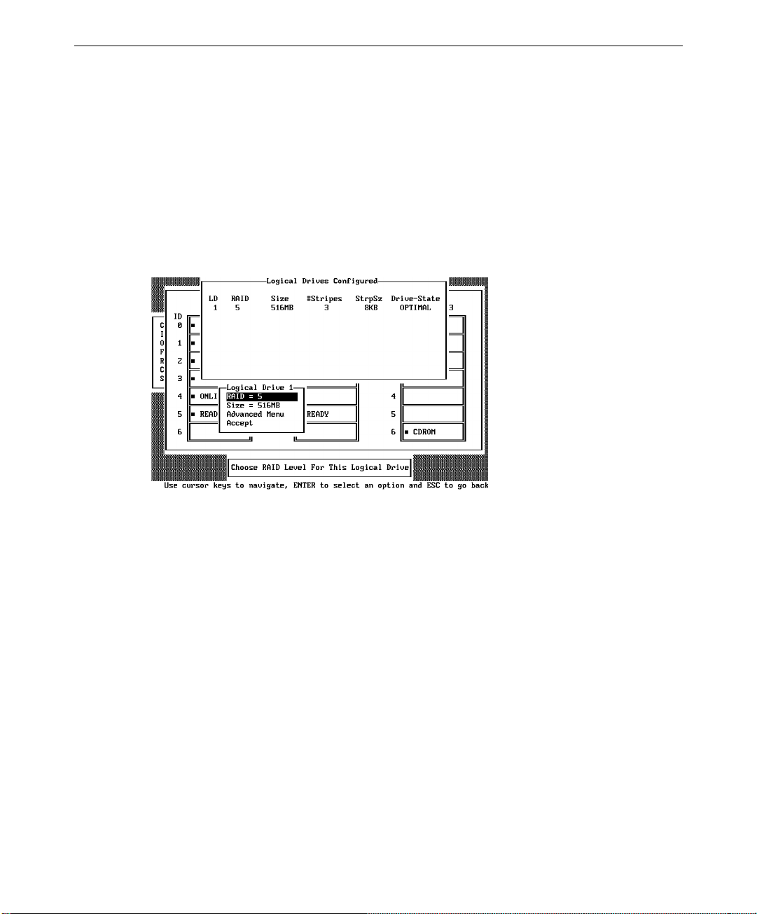
60
The number of physical drives in a specific array determines the RAID levels that can be
implemented with the array.
RAID 0 requires one to eight physical drives per array.
RAID 1 requires exactly two physical drives per array.
RAID 3 requires three to eight physical drives per array.
RAID 5 requires three to eight physical drives per array.
4. Press
ENTER when you are finished creating the current array. The logical drive
configuration screen displays.
The window at the top of the screen shows the logical drive that is currently being
configured as well as any existing logical drives. The column headings are as follows:
LD The logical drive number
RAID The RAID level
Size The logical drive size
#Stripes The number of stripes (physical drives) in the
associated physical array
StrpSz The stripe size
Drive-State The state of the logical drive
5. Set the RAID level for the logical drive. Highlight RAID and press
ENTER. The
available RAID levels for the current logical drive are displayed. Select a RAID level
and press
ENTER to confirm.
Do not use RAID 3 for any logical drive that is to be used as a DOS volume.
Page 75

6. Set the stripe size when this feature becomes available. Set cache write policy, read
policy, and I/O (cache) policy from the Advanced Menu from the bottom window of the
logical drive configuration screen.
The Advanced menu options are as follows:
61
Option
Description
Stripe Size This option sets the stripe size from 2 KB to 128 KB.
Write Policy This option sets the caching method to write-back or write-through. In
Write-back caching, the controller sends a data transfer completion
signal to the host when the controller cache has received all the data in
a transaction.
In Write-through caching, the controller sends a data transfer
completion signal to the host when the disk subsystem has received all
the data in a transaction. This is the default setting.
Write-through caching has a data security advantage over write-back
caching. Write-back caching has a performance advantage over writethrough caching.
Read Policy This option enables the SCSI read-ahead feature for the logical drive.
You can set this parameter to Normal, Read-ahead, or Adaptive.
Normal specifies that the controller does not use read-ahead for the
current logical drive.
Read-ahead specifies that the controller uses read-ahead for the current
logical drive. This is the default setting.
Adaptive specifies that the controller begins using read-ahead if the
two most recent disk accesses occurred in sequential sectors.
Cache Policy This parameter enables the controller cache during data transfers
involving the selected logical drive.
Cached I/O specifies that the controller cache is used. This is the
default setting.
Direct I/O specifies that the controller cache is not used.
7. After setting the options, press
ESC to exit the Advanced Menu.
Page 76

62
8. When you finish defining the current logical drive, highlight Accept from the bottom
window of the logical drive configuration screen, and press
ENTER. The array selection
screen displays if there are any unconfigured disk drives left.
9. Repeat steps 3 through 8 to configure another array and logical drive. MegaRAID
supports up to eight logical drives per controller. If you are finished configuring logical
drives, press
ESC to exit Easy Configuration. A list of the currently configured logical
drives displays:
After you respond to the Save prompt, you will return to the Configure menu.
10. Initialize the logical drives you have just configured as discussed later in this chapter.
Using New Configuration
Follow the steps below to create arrays using New Configuration. The New Configuration
option allows you to associate logical drives with partial and/or multiple physical arrays (the
latter is called spanning of arrays). To use the spanning feature and keep the existing
configuration, use View/Add/Delete Configuration.
Choosing the New Configuration option erases the existing configuration information on the
selected controller.
To use New Configuration:
1. Choose Configure from the Management menu.
2. Choose New Configuration from the Configure menu. An array selection menu shows
the devices connected to the current controller.
Page 77

Hot key information appears at the bottom of the screen. The hot key functions are as
follows:
F2 Display the manufacturer data and error count for the highlighted drive.
F3 Display the logical drives that have been configured.
F4 Designate the highlighted drive as a hotspare .
F10 Display the logical drive configuration screen.
3. Press the arrow keys to highlight specific physical drives. Press the spacebar to
associate the highlighted physical drive with the current array. The indicator for the
selected drive changes from READY to ONLIN A[array number]-[drive number]. For
example, ONLIN A2-3 means disk array 2, drive 3.
63
Add physical drives to the current array as desired. Try to use drives of the same
capacity in a specific array. If you use drives with different capacities in an array, all the
drives in the array are treated as if they have the capacity of the smallest drive in the
array.
The number of physical drives in a specific array determines the RAID levels that can be
implemented with the array.
RAID 0 requires one to eight physical drives per array.
RAID 1 requires exactly two physical drives per array.
RAID 3 requires three to eight physical drives per array.
RAID 5 requires three to eight physical drives per array.
4. Press
ENTER when you finish creating the current array. To continue defining arrays,
repeat step 3. To begin logical drive configuration, go to step 5.
5. Press
F10 to configure logical drives. The logical drive configuration screen displays as
shown:
Page 78

64
The window at the top of the screen shows the logical drive that is currently being
configured as well as any existing logical drives. The column headings are as follows:
LD The logical drive number
RAID The RAID level
Size The logical drive size
#Stripes The number of stripes (physical drives) in the associated physical array
StrpSz The stripe size
Drive-State The state of the logical drive
6. Set the RAID level for the logical drive. Highlight RAID and press
ENTER. A list of the
available RAID levels for the current logical drive displays. Select a RAID level and
ENTER to confirm.
press
Do not use RAID 3 for any logical drive to be used as a DOS volume.
7. Set the spanning mode for the current logical drive. Highlight Span from the bottom
window of the logical drive configuration screen, and press
ENTER. The choices are as
follows:
CanSpan Array spanning is enabled for the current logical drive. The logical drive can
occupy space in more than one array.
NoSpan Array spanning is disabled for the current logical drive. The logical drive can
occupy space in only one array.
For two arrays to be spannable, they must have the same stripe width (they must contain
the same number of physical drives) and must be consecutively numbered. If Array 2
contains four disk drives, it can be spanned only with Array 1 and/or Array 3, and only
if Arrays 1 and 3 also contain four disk drives. If the two criteria for spanning are met,
MegaRAID automatically allows spanning. If the criteria are not met, the Span setting
makes no difference for the current logical drive. Highlight a spanning option and press
ENTER.
Page 79

65
The spanning options are:
Configuring RAID 10, RAID 30, or RAID 50 Logical Drives.
Configure RAID 10 by spanning two to four contiguous arrays, each containing one
RAID 1 logical drive. The RAID 1 logical drives must have the same stripe size. For
example, you can use the span option to configure up to four pairs of RAID 1 drives. Up
to eight physical drives can appear as one large RAID 1 logical drive.
Configure RAID 30 by spanning two to four contiguous arrays, each containing one
RAID 3 logical drive. The RAID 3 logical drives must have the same stripe size.
Configure RAID 50 by spanning two to four contiguous arrays, each containing one
RAID 5 logical drives. The RAID 5 logical drives must have the same stripe size.
8. Set the logical drive size. Move the cursor to Size from the bottom of the logical drive
configuration screen, and press
ENTER.
By default, the logical drive size is set to all available space in the array(s) being
associated with the current logical drive, thus accounting for the Span setting and for
partially used array space. For example, if the previous logical drive used only a part of
the space in an array, the current logical drive size is set to the remaining space by
default.
9. Select Advanced from the bottom window of the logical drive configuration screen to set
the remaining options.
NOTE For a description of the options, refer to the table in “Using Easy Configuration.”
10. After setting the options, press ESC to exit the Advanced Menu.
11. When you finish defining the current logical drive, highlight Accept from the bottom
window of the logical drive configuration screen, and press
ENTER. If there is space
remaining in the arrays, the next logical drive to be configured displays.
12. To configure another logical drive, repeat steps 6 through 9. If the array space has been
used up, a list of the existing logical drives displays. Press any key to continue and
respond to the Save prompt.
13. Initialize the logical drives you have just configured as discussed later in this chapter.
Page 80

66
Using View/Add/Delete Configuration
Follow the steps below to create arrays using View/Add/Delete. View/Add/Delete
Configuration allows you to associate logical drives with partial and/or multiple physical
arrays (this is called spanning of arrays). The existing configuration is left intact when you
select view to look at the current configuration.
To use view/add/delete configuration:
1. Choose Configure from the Management menu.
2. Choose View/Add/Delete Configuration from the Configure menu. An array selection
window displays showing the devices connected to the current controller.
Hot key information appears at the bottom of the screen. The hot key functions are as
follows:
F2 Display the manufacturer data and MegaRAID error count for the highlighted
drive.
F3 Display the logical drives that have been configured.
F4 Designate the highlighted drive as a hotspare .
F5 Delete a logical drive.
F10 Display the logical drive configuration screen.
3. Press the arrow keys to highlight specific physical drives. Press the spacebar to
associate the highlighted physical drive with the current array. The indicator for the
selected drive changes from READY to ONLIN A[array number]-[drive number]. For
example, ONLIN A2-3 means disk array 2, drive 3.
Add physical drives to the current array as desired. Try to use drives of the same
capacity in a specific array. If you use drives with different capacities in an array, all the
drives in the array are treated as if they have the capacity of the smallest drive in the
array.
Page 81

67
The number of physical drives in a specific array determines the RAID levels that can be
implemented with the array.
RAID 0 requires one to eight physical drives per array.
RAID 1 requires exactly two physical drives per array.
RAID 3 requires three to eight physical drives per array.
RAID 5 requires three to eight physical drives per array.
4. Press
ENTER when you finish creating the current array. To continue defining arrays,
repeat step 3. To begin logical drive configuration, go to step 5.
5. Press
F10 to configure logical drives. The logical drive configuration screen displays, as
shown below:
The window at the top of the screen shows the logical drive that is currently being
configured as well as any existing logical drives. The column headings are as follows:
LD The logical drive number
RAID The RAID level
Size The logical drive size
#Stripes The number of stripes (physical drives) in the associated physical array
StrpSz The stripe size
Drive-State The state of the logical drive
6. Set the RAID level for the logical drive. Highlight RAID and press
ENTER. A list of the
available RAID levels for the current logical drive displays. Select a RAID level and
ENTER to confirm.
press
Do not use RAID 3 for any logical drive to be used as a DOS volume.
Page 82

68
7. Set the spanning mode for the current logical drive. Highlight Span from the bottom
window of the logical drive configuration screen and press
ENTER. The choices are:
CanSpan Array spanning is enabled for the current logical drive. The logical drive can
occupy space in more than one array.
NoSpan Array spanning is disabled for the current logical drive. The logical drive can
occupy space in only one array.
For two arrays to be spannable, they must have the same stripe width (they must contain
the same number of physical drives) and they must be consecutively numbered. If Array
2 contains four disk drives, it can be spanned only with Array 1 and/or Array 3, and
only if Arrays 1 and 3 also contain four disk drives. If the two criteria for spanning are
met, MegaRAID automatically allows spanning. If the criteria are not met, the Span
setting makes no difference for the current logical drive. Highlight a spanning option
and press
ENTER.
The spanning options are:
Configuring RAID 10, RAID 30, or RAID 50 Logical Drives.
Configure RAID 10 by spanning two to four contiguous arrays, each containing one
RAID 1 logical drive. The RAID 1 logical drives must have the same stripe size. For
example, you can use the span option to configure up to four pairs of RAID 1 drives. Up
to eight physical drives can appear as one large RAID 1 logical drive.
Configure RAID 30 by spanning two to four contiguous arrays, each containing one
RAID 3 logical drives. The RAID 3 logical drives must have the same stripe size.
Configure RAID 50 by spanning two to four contiguous arrays, each containing one
RAID 5 logical drives. The RAID 5 logical drives must have the same stripe size.
8. Set the logical drive size. Move the cursor to Size from the bottom window of the
logical drive configuration screen and press
ENTER.
By default, the logical drive size is set to all available space in the array(s) being
associated with the current logical drive, thus accounting for the Span setting and for
partially used array space. For example, if the previous logical drive used only a part of
the space in an array, the current logical drive size is set to the remaining space by
default.
9. Select Advanced from the bottom window of the logical drive configuration screen to set
the remaining options.
Page 83

NOTE For a description of the options, refer to the table in “Using Easy Configuration.”
10. After setting the options, press ESC to exit the Advanced Menu.
11. When you finish defining the current logical drive, highlight Accept from the bottom
window of the logical drive configuration screen, and press
ENTER. If there is space
remaining in the arrays, the next logical drive ready to be configured displays.
12. To configure another logical drive, repeat steps 6 through 9. If the array space has been
used up, a list of the existing logical drives displays. Press any key to continue and
respond to the Save prompt.
13. Initialize the logical drives you have just configured as discussed later in this chapter.
Initializing Logical Drives
You should initialize each new logical drive you configure. You can initialize the logical
drives in two ways:
u
Batch Initialization
u
Individual Initialization
To use batch initialization:
69
1. Choose Initialize from the Management menu. A list of the current logical drives
displays, as shown below:
2. Press the arrow keys to highlight all drives. Press the spacebar to select the highlighted
logical drive for initialization. Press
3. When you finish selecting logical drives, press
F2 to select or deselect all logical drives.
F10 and choose Yes at the confirmation
prompt. The progress of the initialization for each drive is shown in bar graph format.
Page 84

70
4. When initialization is complete, press any key to continue. Press ESC to return to the
Management menu.
To use individual initialization:
1. Choose the Objects option from the Management menu. Choose the Logical Drive
option from the Objects menu. The following displays.
2. Select the logical drive to be initialized. The following menu displays:
3. Choose the Initialize option from the action menu. The progress of the initialization
displays as a bar graph on the screen.
4. When initialization completes, press any key to return to the previous menu.
Page 85
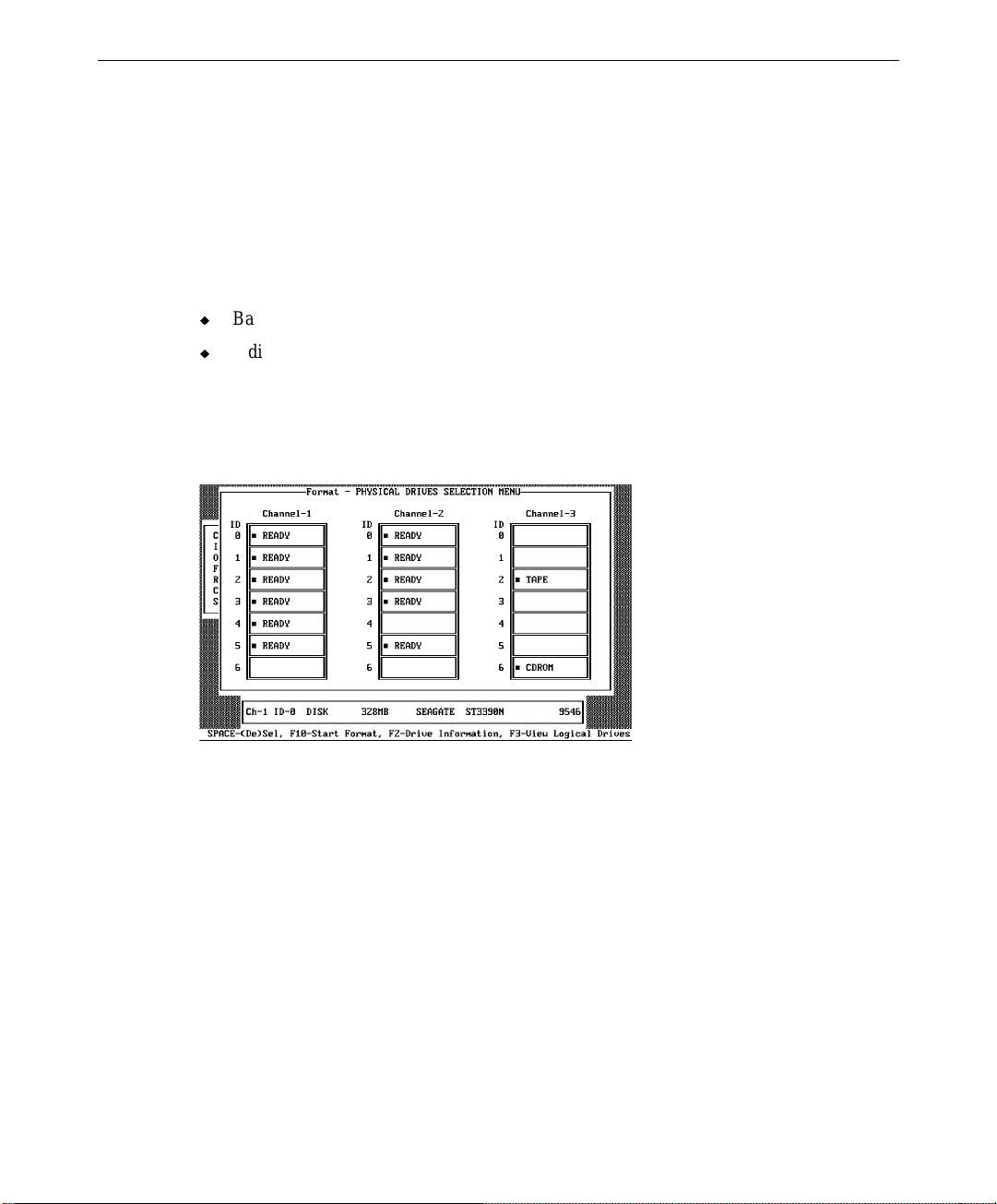
Formatting Physical Drives
Choose the Format option from the Management menu to low-level format one or more
physical drives. A physical drive can be formatted if it is not part of a configuration and is
in a Ready state. Since most SCSI drives are factory formatted, do this step only if the drive
has an excessive number of media errors.
You can format the physical drives in two ways:
u
Batch Formatting
u
Individual Formatting
To use batch formatting:
1. Choose Format from the Management menu. A device selection menu displays,
showing the devices connected to the current controller:
71
2. Press the arrow keys to highlight all drives. Press the spacebar to select the highlighted
physical drive for formatting. The indicators for selected drives flashes.
3. When you are finished selecting physical drives, press
F10 and choose Yes at the
confirmation prompt. The indicators for the selected drives changes to FRMT[number],
where [number] reflects the order of drive selection. Formatting may take some time,
depending on the number of drives you have selected and the drive capacities.
4. When formatting is complete, press any key to continue. Press
ESC to return to the
Management menu.
To use individual formatting:
1. Choose Objects from the Management menu. Choose the Physical Drive option from
the Objects menu. A device selection window displays showing the devices connected to
the current controller:
Page 86

72
2. Press the arrow keys to highlight the physical drive to be formatted and press ENTER.
The following action menu displays:
3. Choose the Format option from the action menu and respond to the confirmation
prompt. Formatting can take some time, depending on the drive capacity.
4. When formatting completes, press any key to return to the previous menu.
Rebuilding Critical Logical Drives
NOTE Logical drives are sometimes referred to as “a pack.”
If a disk drive fails in an array that is configured as a RAID 1, 3, or 5 logical drive, you can
reconstruct the data that was on the failed drive by first replacing the drive. You can then
rebuild the logical drive.
Page 87
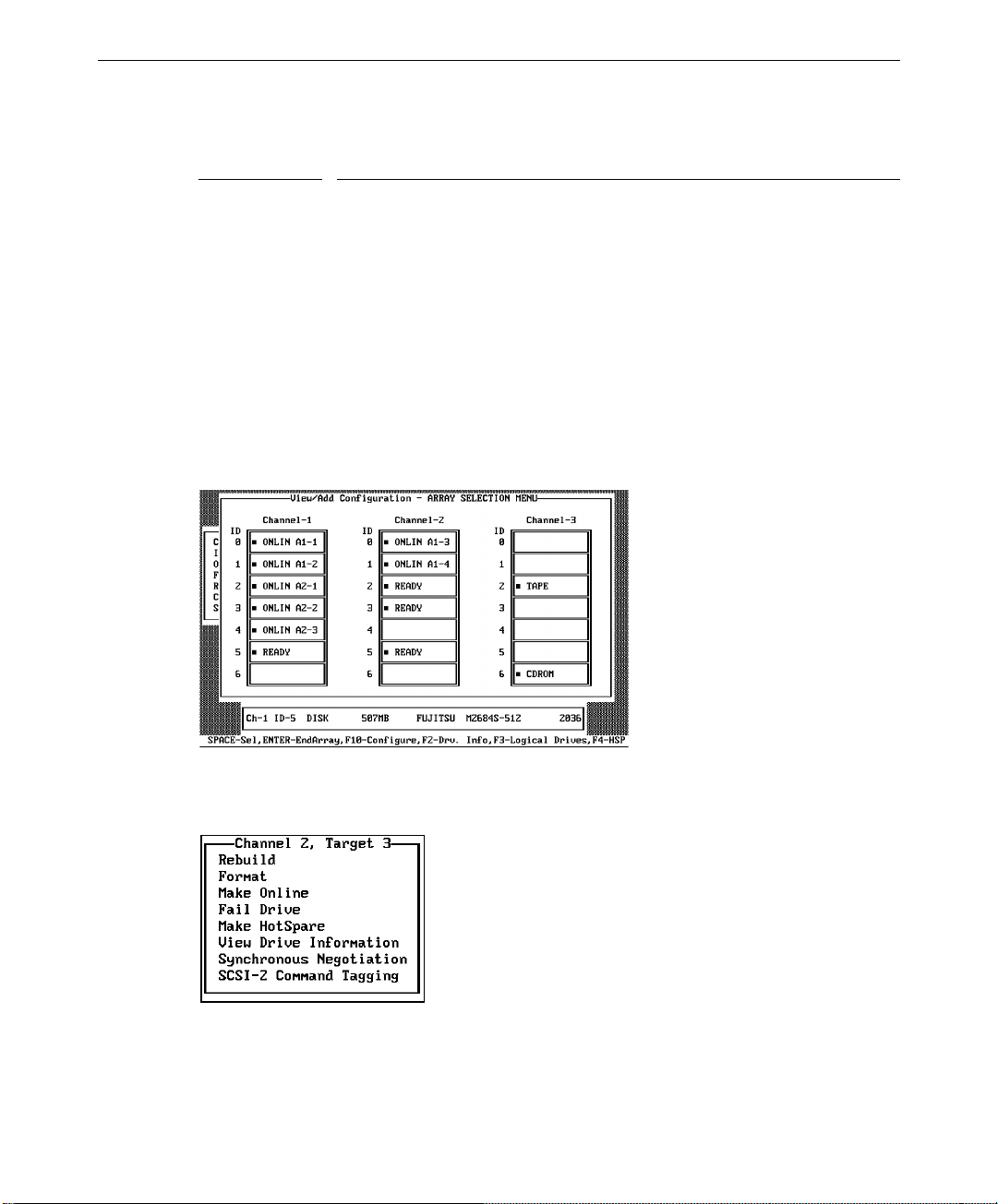
The rebuild types are as follows:
73
Type
Automatic
Rebuild
Description
MegaRAID automatically tries to use hotspares to rebuild failed disk
drives. Display the Objects menu, Physical Drive option screen while a
rebuild is in progress. The drive indicator for the hotspare disk drive
changes to REBLD A[array number]-[drive number], indicating the disk
drive to be replaced.
Manual
Rebuild
Manual rebuild is necessary if there are no hotspares with enough capacity
to rebuild the failed drives.
To rebuild an individual drive using manual rebuild:
1. Choose Objects from the Management menu. Choose Physical Drive from the Objects
menu. A device selection window displays showing the devices connected to the current
controller:
2. Press the arrow keys to highlight the physical drive to be rebuilt and press ENTER. The
following action menu displays:
3. Choose the Rebuild option from the action menu and respond to the confirmation
prompt. Rebuilding can take some time, depending on the drive capacity.
4. When rebuild completes, press any key to return to the previous menu.
Page 88

74
To use batch mode for manual rebuild:
1. Choose Rebuild from the Management menu. A device selection window is displayed
showing the devices connected to the current controller. The failed drives have FAIL
indicators.
2. Press the arrow keys to highlight all drives to be rebuilt. Press the spacebar to select the
highlighted physical drive for rebuild.
3. After selecting the physical drives, press
F10 and select Yes at the confirmation prompt.
The indicators for the selected drives changes to REBLD. Rebuilding can take some
time, depending on the number of drives you have selected and the drive capacities.
4. When rebuild is complete, press any key to continue. Press
ESC to return to the
Management menu.
Using a Pre-loaded SCSI Drive “As-is”
CAUTION To use a pre-loaded drive in the manner described here, you must make it the first logical
drive defined (for example: LD1) on the controller to which it is connected.
You may have a SCSI disk drive that is already loaded with software. The drive may be a
boot disk containing an operating system. You can use the MegaRAID controller as a SCSI
adapter for such a drive by performing the following steps.
To use a pre-loaded SCSI drive:
1. Connect the SCSI drive to one of the channels on the MegaRAID controller, with proper
termination and target ID settings.
2. Boot the system and start Setup by pressing
3. Choose Easy Configuration from the Configure menu.
4. Press the cursor keys to highlight the pre-loaded drive.
CTRL+M.
5. Press the spacebar. The pre-loaded drive should now become an array element.
6. Press
ENTER. You have now declared the pre-loaded drive as a one-disk array. Display
the logical drive configuration screen.
7. Set the read policy and cache policy option on the Advanced menu.
8. Exit the Advanced menu. Highlight Accept and press
9. Press
ESC and choose Yes at the Save prompt.
ENTER.
10. Exit Setup and reboot.
Set the host system to boot from SCSI, if such a setting is available.
Page 89

Saving and Restoring a Configuration
The MegaRAID configuration manager allows you to save the MegaRAID controller’s drive
configurations to a diskette. You should always back up the hardware configuration for
every InterRAID cabinet connected to the system. This section also describes how to restore
a lost hardware configuration to the MegaRAID controller.
Save Configuration to Diskette
To save a configuration to diskette:
1. Ensure the boot sequence for the system is A:, C:.
2. Insert the bootable MegaRAID diskette containing confmgr.exe into the floppy disk
drive.
3. Restart the system. Key in confmgr at the command prompt. The MegaRAID PCI
Adapter Configuration Manager displays:
MegaRAID PCI Adapter Configuration Manager Ver x.xx [July 8 1996].
Adapter 1 found at Base port = 0xec10 Irq= 0xb
75
Save Config to File 1 Restore Config from File 2
Display Adapter Config 3 Display File Config 4
Exit 5
Enter Option -
4. To save the configuration, key in 1 and follow the instructions on the screen. Use a file
name with fewer than twenty characters including the .MEG extension. The following
displays:
Saving configuration...
Press Any Key to Continue.
5. Choose another option, or press 5 to exit.
Restore Configuration to MegaRAID Controller
The MegaRAID configuration manager also allows you to restore to the MegaRAID
controller board a configuration that was corrupted or otherwise lost. The restored
configuration file must match the hardware configuration. MegaRAID assumes the number
of physical drives installed in the InterRAID cabinet is the same as the number of drives
configured in the configuration file.
Page 90

76
To restore a configuration to the MegaRAID controller:
1. At the MegaRAID PCI Adapter Configuration Manager menu, key in 2.
CAUTION In the next step, key in only a MegaRAID configuration file. Restoring any other file will
overwrite the binary code for setting the registers, causing damage to the RAID controller
board. The board must be replaced.
2. Key in the filename for the configuration file at the prompt. Do not include directory
paths. If you used a .MEG extension as part of the filename, include the extension. The
configuration is read from the file and saved on the RAID controller board.
3. Press 5 to exit the configuration manager.
4. Remove the MegaRAID diskette and restart the system.
Page 91

6 Using the Power Console GUI
This chapter describes how to use MegaRAID Power Console. Power Console is an object-
oriented graphics user’s interface (GUI) used to configure and monitor RAID systems
locally. Intergraph Computer Systems includes Power Console on the MegaRAID diskette
delivered with the InterRAID cabinets.
NOTE If you need to reload the MegaRAID driver, follow the instructions in Appendix B “Software
Updates.”
Power Console allows you to control and monitor the status of hard disk drives and the
RAID enclosure. You should understand basic terminology associated with RAID. Refer to
Chapter 8 and the glossary for information on RAID concepts and terminology. The topics
in this chapter include:
u
Identifying Controller Assignments
u
Starting Power Console
u
Identifying Power Console Options
u
Performing Power Console Tasks
77
u
Securing Power Console
Identifying Controller Assignments
If you have more than one MegaRAID controller (referred to as “Adapter” in Power
Console) in a host system, be sure to configure at least one logical drive on every MegaRAID
controller in the host system before you access the controllers from Power Console.
NOTE You can also set up the logical drives as discussed in Chapter 5 using the MegaRAID BIOS
Configuration utility.
Power Console detects the presence of MegaRAID controllers and assigns the controller
numbers in a unique way. The assignments also vary depending on the system’s boot device.
Fixed Hard Disk Drive
Intergraph systems that include a MegaRAID controller but use a fixed disk drive on a
separate controller as a boot device are covered in this section.
Page 92

78
The following tables show how Power Console lists from one to five installed controllers.
One Controller PCI Slot
1 First 0
Two Controllers PCI Slot
1 First 0
2 Second 1
Three Controllers PCI Slot
1 First 0
2 Second 1
3 Third 2
Four Controllers PCI Slot
1 First 0
2 Second 1
3 Third 2
4 Fourth 3
Five Controllers PCI Slot
1 First 0
2 Second 1
3 Third 2
4 Fourth 3
5 Fifth 4
Controller Power Console
Controller Power Console
Controller Power Console
Controller Power Console
Controller Power Console
Page 93

InterServe 615, 625, 635, 645 Systems
InterServe 615, 625, 635, 645 systems are shipped from Intergraph Computer Systems with
RAID controllers installed in PCI slots 1 through 5 which should remain in these slots. On a
system with multiple RAID controllers, always use the RAID controller in PCI slot 1 as the
boot controller. On a system with one RAID controller, the controller resides in PCI slot 1.
The following tables show how Power Console lists the installed controllers.
79
One Controller PCI Slot
1 First 0 (Boot)
Two Controllers PCI Slot
1 First 0 (Boot)
2 Second 1
Three Controllers PCI Slot
1 First 0 (Boot)
2 Second 1
3 Third 2
Four Controllers PCI Slot
1 First 0 (Boot)
2 Second 1
3 Third 2
4 Fourth 3
Five Controllers PCI Slot
1 First 0 (Boot)
2 Second 1
3 Third 2
4 Fourth 3
5 Fifth 4
Controller Power Console
Controller Power Console
Controller Power Console
Controller Power Console
Controller Power Console
Page 94

80
InterServe 8400 and 8000 Systems
InterServe 8400 and 8000 systems are shipped from Intergraph Computer Systems with
RAID controllers installed in PCI slots 4 through 8 which should remain in these slots. On a
system with multiple RAID controllers, always use the RAID controller in PCI slot 4 as the
boot controller. On a system with one RAID controller, the controller resides in PCI slot 4.
The following tables show how Power Console lists the installed controllers.
One Controller PCI Slot
4 First 0 (Boot)
Two Controllers PCI Slot
4 First 0 (Boot)
5 Second 1
Three Controllers PCI Slot
4 First 0 (Boot)
5 Second 1
6 Third 2
Four Controllers PCI Slot
4 First 0 (Boot)
5 Second 1
6 Third 2
7 Fourth 3
Five Controllers PCI Slot
4 First 0 (Boot)
5 Second 1
6 Third 2
7 Fourth 3
8 Fifth 4
Controller Power Console
Controller Power Console
Controller Power Console
Controller Power Console
Controller Power Console
Page 95
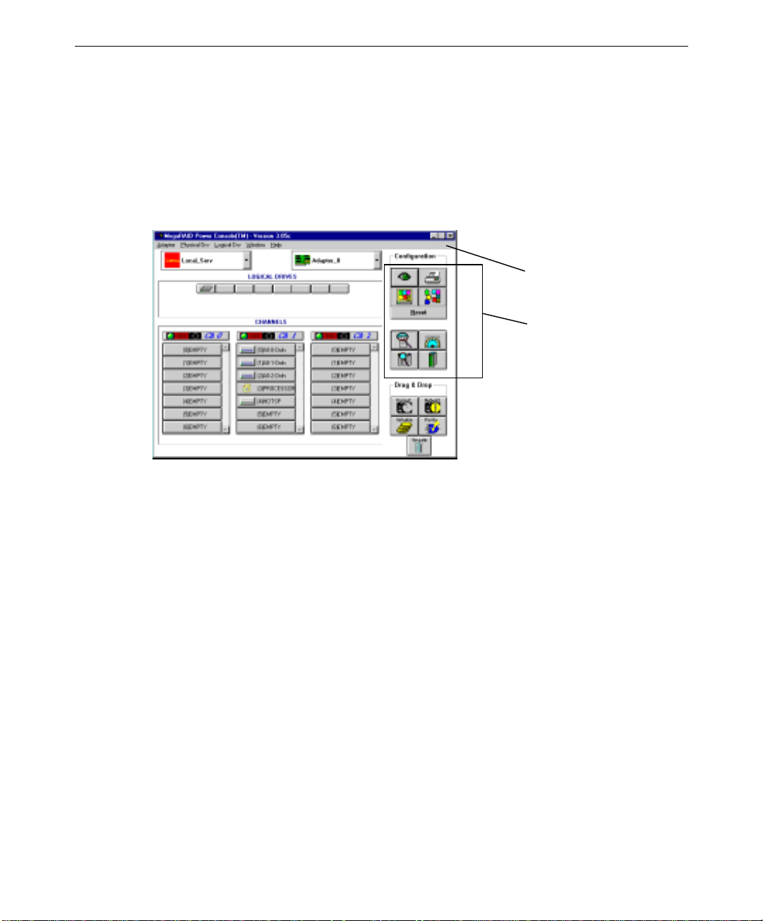
Starting Power Console
Select the MegaRAID Power Console icon from the MegaRAID group in the Windows NT
screen to display the main menu.
NOTE On systems with two-channel MegaRAID controllers, only two columns representing the two
channels will appear on the main menu.
Top Menu
Bar
Toolbox
81
NOTE The toolbox provides convenient access to the features. In lieu of the toolbox you can select
the same features using the top menu bar. Chapter 7 describes the options of the top menu
bar.
The following table defines some terms you will see while configuring drives and running
Power Console.
READY Disk drive ready for configuration
OPTIMAL Disk drive ready for use
ONLINE Disk drive ready for use
REBUILD Disk drive to be replaced
OFFLINE Unformatted drive
PACK Configured pack
DRIVES Number of drives in a pack
SIZE Size of the packs (in megabytes)
HOTSP Disk drive configured as hot spare (standby) drive
EMPTY No disk drive installed
DEGRADED A logical drive has encountered a problem
FAIL A disk drive has failed
Page 96

82
Identifying Power Console Options
Power Console executes from any workstation and runs under Microsoft Windows NT. The
topics discussed in this section include:
u
Configuration Icons
u
Drag and Drop Icons
u
Logical Drives Icons and Logical Drive x menu
u
Channels Icons and Channel x menu
Configuration Icons
The icons are described below.
Display configuration; click on this icon to display the current RAID system
configuration. For example:
Print; click on this icon to make a hardcopy of the current configuration.
Auto configuration; click on this icon to allow MegaRAID to configure the
RAID subsystem.
Page 97

Custom configuration; click on this icon to allow you to configure the RAID
subsystem.
Reset; click on this icon to clear the RAID configuration on the
currently selected controller. A confirmation dialog appears as follows:
Click on OK to reset the configuration or Cancel to abort the process.
83
View log; click here to display a list of MegaRAID activities.
Rebuild rate; click on this icon to set the RAID rebuild drive rate.
Rescan; when you click on this icon, the currently selected MegaRAID
controller rescans its SCSI channels to ensure drive configuration information is current.
Drag and Drop Icons
The icons are described below.
Rebuild disk; drag the physical drive icon that represents the drive to be rebuilt
to this icon to rebuild the selected drive.
Page 98

84
Initialize logical drive; drag the logical drive icon that represents the drive to
be initialized to this icon.
CAUTION If you reset your configuration by mistake, you can recover it by reconfiguring the physical
drives into the same array and logical drive structure they were in, or by saving the
configuration without initializing. Another method is to save the configuration to a floppy.
Logical drive parity check; drag the logical drive icon to this icon to check
parity.
CAUTION Any parity inconsistency will automatically be corrected. This could cause loss or corruption
of data.
Trash; drag the drive icon that represents the drive to be deleted to this icon,
and then drop it.
Logical Drives Icons and Logical Drive x Menu
The following are the logical drives icons:
Status
The indictor light on each logical drive icon indicates its status.
u
Green indicates normal operation.
u
Yellow indicates that the drive performance is degraded.
u
Red indicates a failed drive.
With the cursor placed over one of the device icons, click the right mouse button to display
the Logical Drive x menu. The menu has a list of actions that can be applied to the selected
device. Refer to the following figure:
Page 99

Logical Drive x Menu
You can perform RAID tasks on preconfigured RAID logical drives without halting system
operations. You can select any bolded option from the Logical Drive x pull down menu as
shown in the following dialog:
85
Change Config and
Add Drive Options
Trash Icon
Change Config and Add Drive options extend from the Advanced Menu. For more details
on these options, refer to “Creating an Array” in this chapter.
NOTE The trash can icon in the lower right corner of the MegaRAID Power Console dialog is
available for you to use. For example, to delete a physical drive from a RAID logical drive,
drag and drop a physical drive over the trash can icon.
Page 100

86
Channels Icons and Channel x Menu
The channels icons consist of a stack of drive icons where each device on a SCSI channel is
represented by a disk, CD-ROM, or tape drive icon. The channel indicator light on each
channel icon indicates the status of that channel.
u
Green indicates normal operation.
u
Yellow indicates that the drive performance is degraded.
u
Red indicates a failed drive.
With the cursor over a configured device, click the right mouse button to display the Channel
x pull down menu. The menu lists the bolded options available for that physical device.
Pull Down Menu
for Channel
x
The Deactivate option lasts for 60 seconds when invoked. During this period, the RAID
controller ceases to issue commands on the SCSI bus for a selected channel. By idling the
bus activity in this manner, it assures data integrity when hot swapping disk drives.
CAUTION After a drive fails, do not place the drive back ONLINE or you will get data errors. You
should investigate why the device went offline and correct the problem.
Performing Power Console Tasks
The topics in this section include:
u
Viewing Information
u
Selecting Adapter_x
u
Creating an Array
 Loading...