

Page 1

InterRAID
Hardware User’s Guide
January 1997
DHA018210
Page 2

Warranties and Liabilities
The information and the software discussed in this document are subject to change without notice and
should not be considered commitments by Intergraph Corporation. Intergraph Corporation assumes no
responsibility for any errors in this document.
The software discussed in this document is furnished under a license and may be used or copied only in
accordance with the terms of the license. No responsibility is assumed by Intergraph for the use or
reliability of software on equipment that is not supplied by Intergraph or its affiliated companies.
All warranties given by Intergraph Corporation about equipment or software are set forth in your purchase
contract, and nothing stated in, or implied by, this document or its contents shall be considered or deemed
a modification or amendment of such warranties.
Copyright
1997, Intergraph Corporation including this documentation, and any software and its file formats and
audio-visual displays described herein; all rights reserved; may only be used pursuant to the applicable
software license agreement; contains confidential and proprietary information of Intergraph and/or other
third parties which is protected by copyright, trade secret and trademark law and may not be provided or
otherwise made available without prior written authorization.
Restricted Rights Legend
Use, duplication, or disclosure by the United States Government is subject to restrictions as set forth in
subdivision (c)(1)(ii) of the rights in technical data and computer software clause at DFARS 252.227-
7013.
Unpublished rights reserved under the copyright laws of the United States.
Intergraph Corporation
Huntsville AL 35894-0001
Trademarks
Intergraph and the Intergraph logo are registered trademarks of Intergraph Corporation. InterRAID is
a trademark of Intergraph Corporation.
Microsoft and Windows are registered trademarks of Microsoft Corporation. Windows NT is a
trademark of Microsoft Corporation.
Other brands and product names are trademarks of their respective owners.
Page 3

FCC Compliance
This equipment has been tested and found to comply with the limits for a Class A digital device, pursuant
to part 15 of the FCC Rules. These limits are designed to provide reasonable protection against harmful
interference when the equipment is operated in a commercial environment. This equipment generates,
uses, and can radiate radio frequency energy. If the equipment is not installed and used in accordance
with the instruction manual, it may cause harmful interference to radio communications.
Operation of this equipment in a residential area is likely to cause harmful interference in which case the
user will be required to correct the interference at his own expense.
DOC Compliance
This digital apparatus does not exceed the Class A limits for radio noise emissions from digital apparatus
set out in the Radio Interference Regulations of the Canadian Department of Communications.
Warnings
Changes or modifications made to the system that are not approved by the party responsible for
compliance could void the user’s authority to operate the equipment.
To reduce the risk of electrical shock, do not attempt to open the equipment unless instructed. Do not use
a tool for purposes other than instructed.
There are no user serviceable parts in the power supply. Refer all servicing of the power supply to
qualified service personnel.
There is a danger of explosion if the battery is incorrectly replaced. Replace the battery only with the
same or equivalent type as recommended by the manufacturer. Dispose of used batteries according to the
manufacturer’s instructions.
Cautions
THIS PRODUCT CONFORMS TO THE APPLICABLE REQUIREMENTS OF 21 CFR SUBCHAPTER J
AT DATE OF MANUFACTURE.
Read all safety and operating instructions before using the equipment. Keep these instructions for future
reference. Follow all warnings on the equipment or in the operating instructions.
Page 4

Page 5

Contents
Preface...............................................................................................................................xi
About This Document......................................................................................................... xi
Document Conventions......................................................................................................xii
Finding Operating System Information ..............................................................................xii
Getting Documentation and Training ................................................................................xiii
Getting Telephone Support ............................................................................................... xiii
Using the Intergraph Bulletin Board Service .....................................................................xiv
Using the Intergraph FAXLink ......................................................................................... xiv
Finding Intergraph on the Internet ..................................................................................... xv
1 Getting Started............................................................................................................... 1
Unpacking the Equipment.................................................................................................... 1
Identifying the Operating System Disk Drives......................................................................2
Selecting a Location............................................................................................................. 2
Describing Common Disk Array Features ............................................................................ 2
RAID Controller Board .......................................................................................... 3
Smart Cabinet Monitoring ...................................................................................... 3
SAF-TE Cabinet Monitoring ..................................................................................3
Door Lock..............................................................................................................3
Describing Applicable Intergraph Systems...........................................................................3
Identifying System PCI Slots................................................................................................5
Using the Controller Software.............................................................................................. 5
Determining the RAID Controller ........................................................................................ 6
Connecting the Cabinet........................................................................................................6
v
2 Setting Up and Expanding InterRAID-6....................................................................... 7
Connecting InterRAID-6 to the System................................................................................7
Connecting Remaining Cabinets and Cables ........................................................................8
Expanding the System..........................................................................................................8
Unpacking.............................................................................................................. 9
Setting Up Host...................................................................................................... 9
Installing the RAID Disk Drives ........................................................................................ 10
Powering On and Configuring the System.......................................................................... 12
Important Operating Notices ................................................................................ 12
Important Software Notices..................................................................................13
3 Setting Up and Expanding InterRAID-8..................................................................... 15
Connecting InterRAID-8 to the System.............................................................................. 15
Single-Channel .................................................................................................... 15
Dual-Channel.......................................................................................................16
Connecting Remaining Cabinets and Cables......................................................... 17
Page 6

vi
Expanding the System ........................................................................................................18
Unpacking ............................................................................................................18
Placing Cabinets ...................................................................................................19
Setting Up Host.....................................................................................................20
Installing Multiple Expansions..............................................................................21
Installing the RAID Disk Drives.........................................................................................23
Powering On and Configuring the System ..........................................................................25
Important Operating Notices .................................................................................25
Important Software Notices...................................................................................25
4 Setting Up and Expanding InterRAID-12.................................................................... 27
Connecting InterRAID-12 to the System.............................................................................27
Connecting Remaining Cabinets and Cables ....................................................................... 28
Expanding the System ........................................................................................................29
Unpacking ............................................................................................................29
Placing Cabinets ...................................................................................................29
Setting Up Host.....................................................................................................30
Installing the RAID Disk Drives.........................................................................................31
Powering On and Configuring the System ..........................................................................33
Important Operating Notices .................................................................................33
Important Software Notices...................................................................................34
5 Using DAC InterRAID Utilities....................................................................................35
Updating the DAC960 Driver .............................................................................................35
DACADM and DACMON Utilities....................................................................................36
Starting DACADM...............................................................................................37
DACADM Options...............................................................................................38
DACMON Overview.............................................................................................40
Starting DACMON...............................................................................................40
RAID BIOS Setup..............................................................................................................40
Startup Sequence...................................................................................................41
Error Conditions While Checking the Drives ........................................................41
Overview of DACCF..........................................................................................................42
Starting DACCF................................................................................................................. 43
Main Menu.........................................................................................................................45
01. Automatic Configuration.................................................................................46
02. New Configuration..........................................................................................48
03. View/Update Configuration............................................................................. 56
04. Rebuild ........................................................................................................... 58
05. Initialize System Drive.................................................................................... 59
06. Consistency Check..........................................................................................60
07. Tools...............................................................................................................61
08. Select DAC960 ...............................................................................................66
09. Advanced Functions........................................................................................66
10. Diagnostics .....................................................................................................70
Page 7

vii
Error Conditions ................................................................................................................ 70
Installation Aborted Errors ................................................................................... 70
NVRAM/Flash Configuration Mismatch Errors ................................................... 71
Controller Checksum Errors ................................................................................. 71
Common DACCF Procedures.............................................................................................72
Enabling Automatic Rebuild................................................................................. 72
Changing the Write Policy ................................................................................... 73
Configuring Additional Disk Arrays..................................................................... 73
Recovering Unusable (DED) Disk Drives............................................................. 74
6 Using MegaRAID BIOS...............................................................................................77
Updating the MegaRAID Driver ........................................................................................ 77
Startup Sequence................................................................................................................ 79
Management Menu Options ............................................................................................... 79
Exiting MegaRAID BIOS Configuration Utility................................................................. 80
Management Menu Tree .................................................................................................... 80
Configure Menu................................................................................................... 81
Initialize Menu.....................................................................................................81
Objects Menu....................................................................................................... 81
Format Menu........................................................................................................ 85
Rebuild Menu....................................................................................................... 86
Check Consistency Menu ..................................................................................... 86
Select Adapter Menu............................................................................................ 87
Disable BIOS Menu..............................................................................................87
Configuring Arrays and Logical Drives.............................................................................. 87
Choosing the Configuration Method..................................................................... 88
Designating Drives as Hot Spares......................................................................... 89
Using Easy Configuration..................................................................................... 90
Using New Configuration..................................................................................... 93
Using View/Add Configuration............................................................................ 97
Initializing Logical Drives.................................................................................. 100
Formatting Physical Drives ................................................................................ 101
Rebuilding Failed Disk Drives ......................................................................................... 103
Using a Pre-loaded SCSI Drive “As-is”............................................................................ 105
7 Using Power Console.................................................................................................. 107
Installing the MegaRAID Power Console Utility.............................................................. 107
Overview......................................................................................................................... 108
Power Console Icons........................................................................................................ 109
Configuration Icons............................................................................................ 109
Drag and Drop Icons .......................................................................................... 111
Logical Drive and Channel Icons ..................................................................................... 112
Defining Power Console Menu Options............................................................................ 113
Adapter Menu.................................................................................................................. 114
Configuration..................................................................................................... 116
Flush Cache ....................................................................................................... 118
Page 8

viii
View Log............................................................................................................118
Diagnostics.........................................................................................................118
Enclosure Management.......................................................................................118
Properties............................................................................................................119
Hide/Show Toolbox.............................................................................................120
Performance Monitor..........................................................................................120
Object Identification............................................................................................120
Enable/Disable Sound.........................................................................................121
Enable/Disable Alarm Control ............................................................................ 121
Exit.....................................................................................................................121
Physical Drv Menu...........................................................................................................121
Rebuild...............................................................................................................121
Abort Rebuild.....................................................................................................122
Format................................................................................................................122
Diagnostics.........................................................................................................122
Tools...................................................................................................................122
Properties............................................................................................................122
Logical Drv Menu ............................................................................................................123
Create.................................................................................................................123
Initialize .............................................................................................................124
Check Parity .......................................................................................................125
Properties............................................................................................................126
Logical Drive Menu............................................................................................126
Change Policy.....................................................................................................128
Advanced Menu..................................................................................................128
Removing a Drive.............................................................................................................133
Designating Drives as Hot Spares ..................................................................................... 134
Securing Power Console...................................................................................................134
Saving Configuration to Floppy........................................................................................135
8 Servicing the Disk Array ............................................................................................137
Precautions.......................................................................................................................137
Replacing RAID Controllers.............................................................................................137
Replacing Disk Drives......................................................................................................139
Replacing Power Supplies.................................................................................................139
Replacing Cooling Fans....................................................................................................140
Replacing Cabinets...........................................................................................................141
9 Identifying the RAID Controller Board......................................................................143
DAC960P Controller ........................................................................................................ 143
DAC960PD Controller ..................................................................................................... 144
MegaRAID Controller......................................................................................................145
Features............................................................................................................................145
PCI Bus Interface................................................................................................146
AT Compatible BIOS..........................................................................................146
RAID Controller Firmware .................................................................................146
Page 9

RAID SCSI Bus..................................................................................................146
Components..................................................................................................................... 146
i960 RISC Processor........................................................................................... 146
Cache Memory................................................................................................... 147
PCI Connector.................................................................................................... 147
Flash EEPROM (MegaRAID Only).................................................................... 147
SCSI Controller.................................................................................................. 147
External RAID SCSI Connector (DAC960PD and MegaRAID).......................... 147
Onboard Speaker (MegaRAID Only).................................................................. 147
10 Configuring the Disk Array for Performance......................................................... 149
RAID Technology............................................................................................................ 149
Striped RAID Performance .............................................................................................. 149
Mirrored RAID Performance............................................................................................ 150
Other Performance Options.............................................................................................. 150
Tagged Command Queuing................................................................................ 151
Write-Back Caching........................................................................................... 151
Controller Read Ahead....................................................................................... 151
Database Applications...................................................................................................... 151
RAID Mode Performance and Data Integrity Differences................................................. 152
A Specifications............................................................................................................. 153
InterRAID-6 .................................................................................................................... 153
InterRAID-8 .................................................................................................................... 154
InterRAID-12................................................................................................................... 155
ix
B Troubleshooting......................................................................................................... 157
General............................................................................................................................ 157
Error: System fails to power on.......................................................................... 157
Error: InterRAID drive keeps going dead, same physical drive each time .......... 157
Error: System hangs while loading operating system ......................................... 158
Error: System hangs when scanning devices ...................................................... 158
Error: Installation aborted ................................................................................. 158
Error: “No ROM Basic” message displays......................................................... 158
Error: HDD blinking amber, CHM blinking amber ............................................ 159
Error: HDD blinking green, CHM steady green ................................................. 159
InterRAID-8 and InterRAID-12 ....................................................................................... 159
Error: Information Control Panel displays, “Hardware Error” ............................ 159
Error: Power-On Self Test (POST) fails............................................................. 159
Error: Temperature threshold exceeded ............................................................. 160
InterRAID-8 Only............................................................................................................ 160
Error: All drives are dead .................................................................................. 160
Error: Upper bus drives appear dead and the Information Control
Panel displays, “Starting Single...” ........................................................ 160
Page 10

x
C LED Status Codes and Resource Failures................................................................161
InterRAID LEDs ..............................................................................................................161
Power On LED....................................................................................................163
Power Supply LED..............................................................................................163
Fan LED.............................................................................................................163
Channel Mode LED............................................................................................163
Disk Drive LEDs.................................................................................................164
Power-On Self Test...........................................................................................................164
Microprocessor Failures...................................................................................... 164
RAM Checksum Failure...................................................................................... 165
SCSI Bus Access Failure.....................................................................................165
Hardware and Software Failures .......................................................................................166
InterRAID-8 Power Supply Failures....................................................................166
Disk Drive Rebuild and Disk Drive Failure.........................................................166
Windows NT Server Failure................................................................................167
Removable Media Drive Failure.......................................................................... 167
Glossary ..........................................................................................................................169
Index................................................................................................................................177
Returning Equipment to Intergraph
Returned Goods Authorization (RGA) Form
Shipping Labels
Page 11

Preface
The InterRAID Hardware User’s Guide provides user and technical information about the
InterRAID-6, InterRAID-8, and InterRAID-12 disk array cabinet. It provides instructions
for installing and expanding the disk array cabinets for use with Intergraph’s servers. This
guide provides hardware and software installation procedures, specifications, and
troubleshooting information.
About This Document
The InterRAID Hardware User’s Guide is organized as follows:
u
Chapter 1, “Getting Started,” provides unpacking instructions for the InterRAID
cabinets. It covers identifying the operating system disk drives, selecting a location, and
common disk array features.
u
Chapter 2, “Setting Up and Expanding InterRAID-6,” describes setting up and
expanding the InterRAID-6 cabinet.
xi
u
Chapter 3, “Setting Up and Expanding InterRAID-8,” describes setting up and
expanding the InterRAID-8 single-channel and dual-channel cabinets.
u
Chapter 4, “Setting Up and Expanding InterRAID-12,” describes setting up and
expanding the InterRAID-12 cabinet.
u
Chapter 5, “Using DAC InterRAID Utilities,” describes how to install and use the Disk
Array Controller Administrator (DACADM) and the Disk Array Controller Monitor
(DACMON) utilities. It describes using the RAID controller’s Basic Input Output
System (BIOS) and the Disk Array Controller Configuration (DACCF) utility to manage
the disk arrays. It also covers DACCF error conditions and common procedures.
u
Chapter 6, “Using MegaRAID BIOS,” describes using the MegaRAID BIOS
Configuration utility to manage the disk arrays.
u
Chapter 7, “Using Power Console,” describes using the MegaRAID Power Console
graphics user interface to manage the disk arrays.
u
Chapter 8, “Servicing the Disk Array,” provides information on servicing the disk array.
This chapter includes maintenance procedures for replacing parts of the system.
u
Chapter 9, “Identifying the RAID Controller Board,” illustrates the three types of RAID
controllers used: DAC960P, DAC960PD, and MegaRAID. It provides jumper locations
and identifies internal and external ports.
Page 12

xii
u
Chapter 10, “Configuring the Disk Array for Performance,” discusses the various RAID
hard disk drive configurations and their effects on performance.
u
Appendix A, “Specifications,” includes product specifications.
u
Appendix B, “Troubleshooting,” includes troubleshooting guidelines for the disk arrays.
u
Appendix C, “LED Status Codes and Resource Failures,” provides error conditions that
may occur during the Power-On Self Test (POST) diagnostic. It includes solutions to
miscellaneous hardware and software problems.
Document Conventions
Bold Commands, words, or characters that you key in literally.
Italic Variable values that you supply, or cross-references.
Monospace Output displayed on the screen.
SMALL CAPS Key names on the keyboard, such as D, ALT or F3; names of files and
directories. You can type filenames and directory names in the dialog boxes
or the command line in lowercase unless directed otherwise.
CTRL+D Press a key while simultaneously pressing another key; for example, press
CTRL and D simultaneously.
ALT,SHIFT,F Press keys sequentially; for example, press ALT, then press SHIFT, then
F.
press
Finding Operating System Information
For more information on using the Windows NT operating system, refer to the printed and
online Windows NT documentation from Microsoft:
u
For detailed information on the Windows NT operating system, refer to the online
Windows NT System Guide, delivered on CD-ROM with the operating system, and to
Windows NT Help. You can purchase a printed copy of the System Guide from
Intergraph.
u
For detailed information on installing and updating Windows NT, refer to the Windows
NT Installation Guide.
Page 13

Getting Documentation and Training
You can purchase additional product documentation from Intergraph.
u
In the United States, contact your sales account representative, call the Intergraph Order
Desk at 1-800-543-1054, or send a fax to 1-800-548-3318 to place an order. If you call
or fax the Order Desk, have the document numbers ready for the items you wish to
purchase.
u
Outside the United States, contact the Intergraph subsidiary or distributor from which
you purchased your Intergraph product to place an order.
To find information on training for Intergraph products, or to enroll for an available class,
contact Intergraph Training Solutions at 1-800-240-3000.
Getting Telephone Support
If you experience problems with your Intergraph product, or have questions about the
information in this document, you can contact Intergraph for help.
xiii
u
In the United States, call the Customer Response Center at 1-800-633-7248 between the
hours of 7:00 a.m. and 7:00 p.m. Central Time, Monday through Friday (except
holidays).
u
Outside the United States, contact the Intergraph subsidiary or distributor from which
you purchased your Intergraph product.
Have the following information readily available when you call:
u
The product’s serial number or your service/CPIN number.
u
The product’s name or model number.
u
Your name and telephone number.
u
A brief description of the question or problem.
Page 14

xiv
Using the Intergraph Bulletin Board Service
Available 24 hours a day, 7 days a week, the Intergraph Bulletin Board Service (IBBS) is an
electronic forum for Intergraph customers to exchange information with Intergraph’s
technical and marketing staff, and with other Intergraph customers. You can use the IBBS
to get technical support information, documentation and training information, programs, and
software updates and fixes. The IBBS is also available for you to give suggestions, make
inquiries, and report problems.
To connect to the IBBS:
1. Set your system’s communications protocol for eight (8) data bits, no parity, one (1) stop
bit, and any baud rate up to 14,400.
2. Using a modem, dial the IBBS number, 1-205-730-8786. You can dial 1-205-730-6504
if you are using a 2,400 baud connection.
Mirror sites are maintained for locations outside the United States. Information on these
sites is available on Intergraph Online, Intergraph’s World Wide Web server.
3. When connected, respond to the login request by keying in your user ID. If you have not
connected before, key in new to create a user ID.
4. Follow the menus to find what you need. If you are new to computer bulletin boards, the
IBBS provides clear choices and plenty of online help. A text file that explains IBBS
commands and organization is available for you to download.
If you have trouble connecting to or using the IBBS, log a support request through the
Customer Response Center (product entry IBBS), send a fax to 1-205-730-1110, or leave a
message for the System Operator (Sysop) at 1-205-730-1413.
Using the Intergraph FAXLink
You can use the Intergraph FAXLink to get technical support information by fax 24 hours a
day, 7 days a week. From a touch-tone phone or fax machine phone:
u
Call 1-800-240-4300 to get new user instructions, an index listing of available
documents, and an overview of the categories of available information.
u
Call 1-205-730-9000 to order the documents (up to 5 per call).
Follow the prompts provided to locate and deliver the information you need.
Page 15

Finding Intergraph on the Internet
You can find Intergraph on the Internet in the following ways:
u
If you have a World Wide Web browser, connect to Intergraph Online, Intergraph’s
World WideWeb server, at http://www.intergraph.com. From the home page, follow
the links to Customer Services for information on available customer services and
support options.
u
If you have a File Transfer Protocol (FTP) program, connect to Intergraph at
ftp.intergraph.com.
u
If you have a Gopher program, connect to Intergraph at gopher.intergraph.com.
u
You can get information from Intergraph’s email server at info@intergraph.com. Put
help in the body of the message (the subject line is ignored) to get information on such
subjects as Intergraph’s online services and where to get World Wide Web browsers.
u
You can participate in the Intergraph Customer Forum (ICF), a bidirectional gateway to
the USENET newsgroup comp.sys.intergraph. Anything posted to that group or sent to
comp-sys-intergraph@ingr.com is emailed to all subscribers. Incoming email
messages are also posted to the newsgroup. You can subscribe to the ICF via Intergraph
Online.
xv
Page 16

1 Getting Started
The InterRAID-6, InterRAID-8, and InterRAID-12 disk array cabinets are easy to set up and
connect to an Intergraph desktop or deskside system. This document assumes the system
base unit is already set up.
NOTE To unpack and connect the rack-mount InterRAID-8 cabinet, refer to the hardware
documentation for the rack-mounted system.
Unpacking the Equipment
Carefully unpack the equipment. The carton contains the following items:
u
InterRAID cabinet
u
Disk drive box with RAID disk drives
u
Key
1
u
Diskettes containing configuration and utility software
u
Accessory pack
The accessory pack, included with the cabinet, contains the following items:
u
InterRAID cabinet power cord
u
RAID SCSI cable
u
Four plastic feet
u
Eight cap head hex screws
u
Hex wrench
u
Disk drive labels
u
Drive Labeling instruction sheet
u
Power Supply Cord Selection instruction sheet
u
Feet Installation instruction sheet
u
Antistatic Handling instruction sheet
u
Rubber pads (InterRAID-8 and InterRAID-12)
u
Blanking plate (InterRAID-8)
Page 17

2
Retain all packaging materials. Equipment returned for repair must be in the original
packaging to obtain warranty service, if provided under your contract agreement.
NOTE If any of the listed parts are missing or damaged, call the Intergraph Customer Response
Center at 1-800-633-7248.
Identifying the Operating System Disk Drives
The box containing the operating system disk drives is labeled, “This box contains disk
drives loaded with operating system software...” Each operating system drive is labeled with
the SCSI ID number. If additional cabinets are purchased, the RAID disk drives for these
cabinets will not contain the operating system software and will not be labeled.
CAUTION Do not remove the RAID disk drives from the antistatic bags until you are ready to install
them in the InterRAID cabinet.
Selecting a Location
The InterRAID cabinets can be placed side-by-side or stacked. Keep the following in mind
when selecting a location.
u
Allow six inches of space in front of the cabinet for the door to open.
u
Allow at least a three-inch clearance in back of the cabinet for air circulation.
u
Place the cabinet on a hard, flat surface (not on carpet).
u
Ensure the surface will support the weight of the cabinets with all RAID disk drives
installed, as follows:
−
InterRAID-6 weighs approximately 38 pounds.
−
InterRAID-8, rack-mount, weighs approximately 84 pounds.
−
InterRAID-8, tower, weighs approximately 75 pounds.
−
InterRAID-12 weighs approximately 75 pounds.
Describing Common Disk Array Features
The following features are common to the InterRAID-6, InterRAID-8, and InterRAID-12
expansion solutions.
Page 18

RAID Controller Board
The RAID controller board incorporates a 32-bit RISC processor to control all functions
including SCSI bus transfers, RAID processing, configuration, data striping, error recovery,
and drive building.
Smart Cabinet Monitoring
The cabinet uses an intelligent interface (microprocessor) to alert the user in the event of an
abnormal system condition. The microprocessor resides on the SCSI bus and communicates
the level of fault-tolerance to the user through software, LEDs, and audible alarms. The
cabinet monitors its disk drives, power supplies, cooling fans and temperature and
continually reports to the LEDs and the Information Control Panel.
NOTE The InterRAID-6 cabinet does not have an Information Control Panel.
SAF-TE Cabinet Monitoring
SCSI Accessed Fault-Tolerant Enclosure (SAF-TE) is a new method to alert the user of
abnormal system conditions. SAF-TE, in addition to the Smart Cabinet monitoring
functions listed above, allows reporting to the system of the cooling fan revolutions per
minute, power supply voltages and temperature in degrees, number of insertions per slot, and
number of powerup hours.
3
Door Lock
The front door uses an integrated door lock to prevent unauthorized access to the internal
components. Two keys are provided with the cabinet. To unlock the door, insert the key and
turn it counterclockwise. To lock the door, turn the key clockwise.
NOTE After inserting the key into the lock, the key can only be removed when the door is locked.
Describing Applicable Intergraph Systems
The dual-channel InterRAID-8 is available as a deskside (tower) unit, and the rack-mount
version is available as dual-channel and single-channel, depending on the system to which it
is attached.
Page 19

4
The following tables list current InterRAID cabinets, systems, controllers, and applicable
software.
InterRAID-6
Single-channel
Tower
InterRAID-8
Dual-channel
Tower
Dual-channel
Rack-mount
Single-channel
Rack-mount
Intergraph System Controller/Software Cabinet Software
DTP Server (TD-40)
InterServe 21
InterServe 32
DAC960xx with
DACCF, DACADM,
and DACMON utilities
Smart Cabinet
TD-30, TD-40
TDZ-600, TDZ-610
Intergraph System Controller/Software Cabinet Software
InterServe 610, 620,
630, 640
DAC960xx with
DACCF, DACADM,
Smart Cabinet
and DACMON utilities
StudioZ RAX
MegaRAID with
SAF-TE Cabinet
MegaRAID BIOS setup
and Power Console
utilities
InterServe 650, 660
MegaRAID with
SAF-TE Cabinet
MegaRAID BIOS setup
and Power Console
utilities
Dual-channel
Tower
InterServe 615, 625,
635, 645
MegaRAID with
MegaRAID BIOS setup
SAF-TE Cabinet
and Power Console
utilities
InterRAID-12
Dual-channel,
Tower
NOTE To determine which version of cabinet software is on your disk array cabinet(s), select the
following from the LCD Panel: Menu => Hardware => Firmware revision. A Smart cabinet
array will display a blank. A SAF-TE cabinet array will report SAF-TE on the top line of the
display.
Intergraph System Controller/Software Cabinet Software
InterServe 62, 64, 66
InterServe 610, 620,
630, 640
DAC960xx with
DACCF, DACADM,
and DACMON utilities
Smart Cabinet
Page 20

Intergraph does not recommend striping a 2-pack or logical drive across Smart cabinets and
SAF-TE cabinets. For more information on striping, refer to the appropriate chapter in this
guide for the installed controller and the applicable software utility. DAC960xx with
DACCF, DACADM, and DACMON utilities are found in Chapter 5. MegaRAID with
MegaRAID BIOS setup and Power Console utilities are found in Chapter 6 and Chapter 7,
respectively.
Identifying System PCI Slots
The following figures indicate PCI slot numbers for Intergraph’s system base units.
Slot 1
Slot 3
Slot 1
Slot 3
5
TD-xx, TD-xxx
TD-x10, TDZ-x10
Slot 1
Slot 6
Using the Controller Software
Your system shipped with either a DAC960xx or a MegaRAID controller and the associated
software. Be sure to determine which controller board is installed and use the proper
software when configuring. Chapter 5 contains the software instructions for the DAC960P
and DAC960PD controllers, and Chapters 6 and 7 contains the software instructions for the
MegaRAID controller.
DTP Server, InterServe 21
InterServe 6xx, TD-xx, TD-xxx,
TDZ-xx, TDZ-xxx
Page 21

6
Determining the RAID Controller
You can determine which RAID controller is installed in your system by viewing the BIOS
banner during the boot process. Chapters 5 and 6 provide examples of the BIOS banner for
the appropriate RAID controller. Refer to Chapter 5 for either a DAC960P or DAC960PD
controller, or Chapter 6 for a MegaRAID controller.
Connecting the Cabinet
Use the appropriate instructions in this guide when connecting the cabinet to the system base
unit.
u
For InterRAID-6 cabinets, refer to Chapter 2, “Setting Up and Expanding
InterRAID-6.”
u
For InterRAID-8 cabinets, refer to Chapter 3, “Setting Up and Expanding
InterRAID-8.”
u
For InterRAID-12 cabinets, refer to Chapter 4, “Setting Up and Expanding
InterRAID-12.”
Page 22

2 Setting Up and Expanding
InterRAID-6
To set up the InterRAID-6 disk array with a system base unit, you will perform the following
tasks:
u
Connect the InterRAID-6 cabinet to the system base unit.
u
Expand the system (if installing additional disk arrays).
u
Install the RAID disk drives.
u
Power on and configure the system.
Connecting InterRAID-6 to the System
To connect the InterRAID-6 cabinet:
7
1. Connect the RAID SCSI cable to the RAID SCSI port on the RAID controller board
installed in the system base unit.
RAID
Controller
Board in
Base Unit
InterRAID-6
RAID SCSI
Port
2. Connect the other end of the RAID SCSI cable to the RAID SCSI port on the
InterRAID-6 cabinet.
Page 23

8
Connecting Remaining Cabinets and Cables
To connect the remaining cabinets and cables:
1. Choose the proper power cord for the cabinet. Refer to the Power Supply Cord Selection
instruction sheet included in the accessory pack.
2. Connect the power cord to the InterRAID-6 cabinet. Lift the power cord retainer, insert
the power cord, and lower the retainer into place over the power cord.
3. Connect the other end of the power cord to an Uninterruptible Power Supply (UPS), if
available, or to a grounded, three-prong AC power outlet.
CAUTION If the system does not connect to a UPS, data loss can occur if there is a power failure.
4. If you have additional cabinets, connect the RAID SCSI cables and power cords in the
same manner as instructed above.
5. For Intergraph deskside systems, use the following table as a guide to install any
secondary RAID controller boards.
Number of
RAID
Controllers
One PCI Slot 3 - - Two PCI Slot 3 PCI Slot 2 - Three PCI Slot 3 PCI Slot 2 PCI Slot 1 Four PCI Slot 3 PCI Slot 2 PCI Slot 1 PCI Slot 6
Primary Secondary Secondary Secondary
−
If PCI Slot 6 is not available, use PCI Slot 5.
−
For DTP Server systems, the boot drive will be in the external disk array attached to
the primary RAID controller board.
−
For Intergraph desktop and deskside systems with an internal hard disk drive, the
boot drive is the internal hard disk drive and does not require connection to a
primary RAID controller board. Any external cabinets and associated RAID
controller boards are secondary.
Expanding the System
This section provides instructions to expand the following systems with additional
InterRAID-6 disk arrays:
u
InterServe 21, 22, and 32
Page 24

Unpacking
u
DTP Server
u
TD-xx (desktop and deskside)
The following describes unpacking, setting up, and connecting the InterRAID-6 Expansion
Solution to your system.
Carefully unpack the InterRAID-6 Expansion Solution equipment, and verify that you have
the following items:
u
InterRAID-6 cabinet
u
Key for cabinet door
u
RAID disk drives
u
Diskettes containing configuration and utility software
u
Documentation
u
Antistatic wrist strap
9
u
Accessory pack containing a power cord, RAID SCSI cables, four plastic feet, eight cap
head screws, one hex wrench, disk drive labels, rubber pads, a blanking plate, a Drive
Labeling sheet, a Feet Installation sheet, a Power Supply Cord Selection sheet, and an
Antistatic Handling sheet
The Expansion Solution equipment may also include a RAID controller board.
CAUTION Do not remove the RAID disk drives from the antistatic bags until you are ready to install the
drives in the cabinet. Do not handle the RAID disk drives unless you connect an antistatic
wrist strap to your wrist and to a bare metal surface on the cabinet.
Retain all packaging materials. You must return the system in the original packaging to
obtain warranty service. Refer to the instructions in the back of this guide for returning
equipment to Intergraph.
Setting Up Host
The following provides instructions for setting up the host system for use with an
InterRAID-6 Expansion Solution RAID controller board.
Page 25

10
To set up the host for use with InterRAID-6:
1. If your Expansion Solution came with a RAID controller board, install it into the
appropriate PCI slot in the system’s base unit. Refer to Chapter 1, “Getting Started,” for
PCI slot designations. Refer to your system’s documentation for instructions on opening
the base unit, taking precautions against electrostatic discharge, and installing option
boards.
−
On InterServe 21, DTP Server, and TD-xx deskside systems, the primary RAID
controller is installed in PCI slot 3. Install additional (secondary) controllers in PCI
slots 2, 1, and 6 (in that order). If PCI slot 6 is not available, use PCI slot 5.
−
On TD-xx desktop systems, the primary RAID controller may be installed in PCI
slot 1 or PCI slot 2, whichever is available. Install a secondary controller in the
other slot.
−
On InterServe 22 and 32 systems, the primary RAID controller is installed in PCI
slot 2. Install additional (secondary) controllers in PCI slots 3, 4, and 5.
−
On DTP Server systems, the boot disk drives are in the InterRAID disk array
connected to the primary RAID controller.
−
For Intergraph desktop and deskside systems with an internal hard disk drive, the
internal hard disk drive is the boot disk drive and does not require connection to a
primary RAID controller. Any external disk arrays and associated RAID
controllers are secondary.
2. Route and connect the RAID SCSI cables and power cables to the back of each cabinet.
Installing the RAID Disk Drives
The InterRAID-6 cabinet contains up to six 1.0-inch high, 3.5-inch form factor RAID disk
drives. Supported capacities include 1 GB, 2 GB, 4 GB, and higher as the disk drives
become available. Contact an Intergraph sales representative for drive availability. The lefthand side of the disk drive label identifies the disk drive size.
NOTE Intergraph attaches a SCSI ID number to the disk drive label to identify each of the boot disk
drives. All other disk drives are for data storage and do not specify a SCSI ID number.
CAUTION Ensure you install the boot disk drives into the InterRAID-6 cabinet that connects to the
primary RAID controller board.
To install the RAID disk drives:
1. Unlock the front panel door using the key for the InterRAID-6 cabinet.
Page 26

2. Remove the RAID disk drives from the carton labeled, “This box contains disk drives
loaded with operating system software....” For TD-xx desktop and deskside systems, the
first three drives (ID 0, 1, 2) contain the operating system. For the DTP Server systems,
all six disk drives contain the operating system.
The following table shows the order in which to install the boot disk drives:
11
Disk Drive Label
InterRAID-6 Slots
ADP CHN ID 6 Slot 6 (Top)
ADP CHN ID 5 Slot 5
ADP CHN ID 4 Slot 4
ADP CHN ID 2 Slot 3
ADP CHN ID 1 Slot 2
ADP CHN ID 0 Slot 1 (Bottom)
3. Install the boot disk drives in the primary InterRAID-6 cabinet. To insert a drive,
extend the drive latching clips and slide the drive into the slot. Push between the
latching clips until the drive connects. Close the drive latching clips until they snap into
place, locking the drive into the slot. Refer to the following figure.
CAUTION Carefully insert the disk drives to avoid damaging the Single Connector Attachment (SCA)
connector.
Power Switch
Drive
Latching
Clips
(Open)
Slot 1
4. Install the remaining RAID disk drives without labels into the primary cabinet. You can
install them in any order as long as the slots are filled sequentially upward (for example,
do not install drives in slots 4 and 6, leaving slot 5 empty).
Page 27

12
5. If necessary, fill in the label information for each RAID disk drive. Refer to the Drive
Labeling instruction sheet. The disk drive label has blank spaces for you to apply the
appropriate numbers to indicate the RAID controller board number (ADP X), channel
number (CHN Y), and SCSI ID number (ID Z). In the following table, Intergraph
reserves SCSI ID 3 for the entire disk array. All six RAID disk drives connect to a
single channel.
Use the following table to label the drives:
Disk Drive Label
ADP X CHN 0 ID 6 Slot 6 (Top)
ADP X CHN 0 ID 5 Slot 5
ADP X CHN 0 ID 4 Slot 4
ADP X CHN 0 ID 2 Slot 3
ADP X CHN 0 ID 1 Slot 2
ADP X CHN 0 ID 0 Slot 1 (Bottom)
6. If you have additional cabinets, install the RAID disk drives and complete the drive
label information as appropriate.
InterRAID-6 Slots
Powering On and Configuring the System
To prevent accidental power off or on, the power switch is recessed and not accessible with
the door closed and locked. Before starting the system for the first time, read the following
important operating and software notices.
Important Operating Notices
u
Always power on the InterRAID-6 cabinet and wait for the audible beep before powering
on the system base unit.
u
If you are installing RAID disk drives that are partially loaded with the Windows NT
Server operating system, you must complete installation of the operating system before
configuring your RAID disk array. If you do not complete installation, or if you turn off
the power to the system base unit before completing the Windows NT Server setup
procedures, you must reload the operating system. Once you power on the system base
unit, do not power off the system without completing Windows NT Server installation.
Page 28

u
Always power off the system base unit before powering off the InterRAID-6 cabinet. If
you power off the cabinet first, the RAID controller board will read the drives as dead
the next time you power on the system. Refer to Chapter 5 “Using DAC InterRAID
Utilities,” or Chapter 6 “Using MegaRAID BIOS” and Chapter 7, “Using Power
Console.”
Important Soft ware Notices
u
For DTP Server systems, Intergraph installs the Microsoft Windows NT Server
operating system software and prepares it for final configuration by users.
u
For desktop and deskside systems other than the DTP Server, the disk drives are
delivered with Microsoft Windows NT Server operating system software partially
installed. You must complete Windows NT Server installation before using the system.
u
The RAID controller board has two types of write caching: write-back and writethrough. Write-through caching reduces the risk of data loss in the event of a power
failure. Write-back caching improves performance, but the drawback is potential data
loss if power fails. Intergraph recommends connection to a UPS to guard against data
loss.
u
Intergraph configures the RAID controller board to RAID level 5. RAID controllers
support RAID levels 0, 1, 5, 6 (0+1), and 7. The MegaRAID controller, in addition to
the other levels, also supports RAID level 3.
13
To power on and configure the system:
1. Power on the InterRAID-6 cabinet and wait for the audible beep.
2. Power on the system base unit and the monitor.
3. Complete the Windows NT Server installation. Refer to the system’s setup or
configuration documentation.
4. Install the proper software utilities available for the RAID controller board installed in
the system.
For DAC960P and DAC960PD boards, install the DACADM and DACMON utilities.
Refer to Chapter 5, “Using DAC InterRAID Utilities.”
For MegaRAID boards, install the MegaRAID BIOS and Power Console utilities. Refer
to Chapter 6, “Using MegaRAID BIOS” and Chapter 7, “Using Power Console.”
WARNING After you configure the RAID disk drives, it is very important that you backup the
configuration to a diskette. It will be very helpful for future use in the event the
configuration should become lost. Refer to Chapter 5 “Using DAC InterRAID Utilities,”
or Chapter 6 “Using MegaRAID BIOS” and Chapter 7, “Using Power Console.”
Page 29

14
5. If necessary, configure the RAID controller board to your preferences. Refer to Chapter
5 “Using DAC InterRAID Utilities,” or Chapter 6 “Using MegaRAID BIOS” and
Chapter 7, “Using Power Console.”
6. Use Disk Administrator in Windows NT to partition and format the disk space not used
by the operating system. When prompted to create a Signature File, select Yes. Refer to
the Windows NT Server System Guide for information on using Disk Administrator.
Page 30

3 Setting Up and Expanding
InterRAID-8
To set up the InterRAID-8 disk array with a system base unit, you will perform the following
tasks:
u
Connect the InterRAID-8 cabinet to the system base unit.
u
Expand the system (if installing additional disk arrays).
u
Install the RAID disk drives.
u
Power on and configure the system.
Connecting InterRAID-8 to the System
When setting up the InterRAID-8 cabinet in a vertical position, install the plastic feet on the
cabinet according to the Feet Installation instruction sheet. If setting up the cabinet
horizontally, install the rubber pads on the cabinet in the recessed area of each corner.
15
NOTE To connect the rack-mount InterRAID-8 cabinet, refer to the system’s hardware
documentation for the rack-mounted system.
InterRAID-8 is available in two configurations, single-channel and dual-channel. The
single-channel cabinet has eight devices on one SCSI channel, and the dual-channel cabinet
has four devices on each of two SCSI channels. To determine whether you have a singlechannel or a dual-channel cabinet, look at the back of the cabinet. The single-channel
InterRAID-8 cabinet has only one SCSI port; the dual-channel cabinet has two SCSI ports.
Single-Channel
To connect the single-channel InterRAID-8 cabinet:
1. Connect one end of the RAID SCSI cable to the SCSI port on the InterRAID-8 cabinet.
Page 31

16
2. Connect the other end of the RAID SCSI cable to the channel 0 port on the RAID
Dual-Channel
Channel 0
controller board in the system base unit.
RAID
Controller
Board in Base
Unit
To connect the dual-channel InterRAID-8 cabinet:
1. Connect a RAID SCSI cable to the channel 0 port on the RAID controller in the base
unit, and to the channel 0 port on the InterRAID-8 cabinet.
Channel 1
RAID
Controller
Board in Base
Unit
Channel 0
2. Connect a RAID SCSI cable to the channel 1 port on the RAID controller board in the
base unit, and to the channel 1 port on the InterRAID-8 cabinet.
Page 32

Connecting Remaining Cabinets and Cables
To connect the remaining cabinets and cables:
1. Choose the proper power cord for the cabinet. Refer to the Power Supply Cord Selection
instruction sheet included in the accessory pack.
2. Connect the power cord to the InterRAID-8 cabinet.
3. Connect the other end of the power cord to an Uninterruptible Power Supply (UPS), if
available, or to a grounded, three-prong AC power outlet.
CAUTION If the system does not connect to a UPS, data loss can occur if there is a power failure.
4. If you have additional cabinets, connect the RAID SCSI cables and power cords in the
same manner as instructed above.
5. Use the following table as a guide to install any secondary RAID controller boards.
Number of
RAID
Controllers
One PCI Slot 3 - - Two PCI Slot 3 PCI Slot 2 - Three PCI Slot 3 PCI Slot 2 PCI Slot 1 Four PCI Slot 3 PCI Slot 2 PCI Slot 1 PCI Slot 6
Primary Secondary Secondary Secondary
17
−
If PCI Slot 6 is not available, use PCI Slot 5.
−
For Intergraph deskside systems with internal RAID, the internal RAID subsystem
already contains the boot drives. The primary RAID controller board connects to
the internal RAID subsystem.
−
For Intergraph deskside systems with an internal hard disk drive, the boot drive is
the internal hard disk drive and does not require connection to a primary RAID
controller board. Any external cabinets and associated RAID controller boards are
secondary.
Page 33

18
For InterServe 650, 660 systems, use the following table as a guide to install any
secondary RAID controller boards.
Number of
RAID
Controllers
Primary Secondary Secondary Secondary
One PCI Slot 7 - - Two PCI Slot 7 PCI Slot 6 - Three PCI Slot 7 PCI Slot 6 PCI Slot 5 Four PCI Slot 7 PCI Slot 6 PCI Slot 5 PCI Slot 4
Expanding the System
This section provides instructions to expand your InterServe 6xx system with additional
InterRAID-8 disk arrays. The following describes unpacking, placing cabinets, installing
internal expansion cables, and installing multiple expansions.
Unpacking
Carefully unpack the InterRAID-8 Expansion Solution equipment, and verify that you have
the following items:
u
InterRAID-8 cabinet
u
Key for cabinet door
u
RAID disk drives
u
Diskettes containing configuration and utility software
u
Documentation
u
Antistatic wrist strap
u
Accessory pack containing a power cord, RAID SCSI cables, four plastic feet, eight cap
head screws, one hex wrench, disk drive labels, rubber pads, a blanking plate, a Drive
Labeling sheet, a Feet Installation sheet, a Power Supply Cord Selection sheet, and an
Antistatic Handling sheet
The Expansion Solution equipment may also include the following items:
u
RAID controller board
u
Internal expansion cable
u
RAID SCSI cable
Page 34

CAUTION Do not remove the RAID disk drives from the antistatic bags until you are ready to install the
drives in the cabinet. Do not handle the RAID disk drives unless you connect an antistatic
wrist strap to your wrist and to a bare metal surface on the cabinet.
Retain all packaging materials. You must return the system in the original packaging to
obtain warranty service. Refer to the instructions in the back of this guide for returning
equipment to Intergraph.
Placi ng Cabinets
To place the cabinets side-by-side:
1. Place the feet on the bottom of the cabinet as described in the Feet Installation sheet.
2. Set the cabinet a few inches away from the existing cabinets.
To stack the cabinets:
1. If existing InterRAID cabinets are not already stacked, remove the RAID disk drives
from them and place the drives on an antistatic surface.
CAUTION Keep track of the drive locations. You must install the drives in the same cabinets and slots
from which you remove them.
19
2. To rotate the Information Control Panel on the cabinet door, open the cabinet door and
remove the folded section of ribbon cable from the slit in the Mylar on the back of the
door.
3. Using a 5/16-inch nutdriver, remove the hex nuts from the corners of the Information
Control Panel.
4. Rotate the Information Control Panel one-quarter turn counterclockwise and re-attach it
to the door with the hex nuts. Do not overtighten the nuts.
5. Close the cabinet door.
6. Place the rubber pads from the accessory pack into the recessed locations on the left side
(as viewed from the front) of the cabinet.
7. Place the bottom cabinet on its rubber pads on a flat, hard surface (not on carpet).
8. For each additional InterRAID cabinet you want to stack, repeat steps 2 through 6 and
place the additional cabinet on top of the previous cabinet.
CAUTION You may stack up to four InterRAID cabinets in a single stack.
9. If you removed RAID disk drives from existing InterRAID cabinets, replace them.
Page 35
20
Setting Up Host
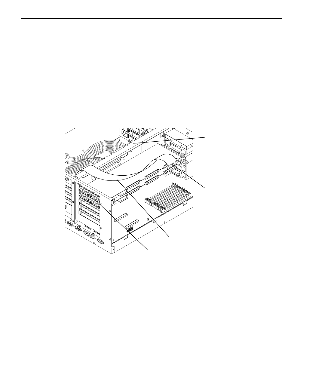
The following provides instructions for installing the internal expansion cable in the host to
use Channel 2 of the secondary RAID controller board.
To set up host for use with InterRAID-8:
1. Connect the internal expansion cable to the Channel 2 connector of the secondary RAID
controller board as shown in the following figure (here, the secondary RAID controller
is installed in PCI slot 2).
2. Route the internal expansion cable over the option board bracket as shown in the
following figure.
Option Board
Bracket
Channel 2
Internal Expansion Cable
PCI Slot 2
3. Using a quarter-inch nutdriver, remove the screw securing the ISA I/O lock bracket as
shown in the following figure. Remove the lock bracket.
Page 36
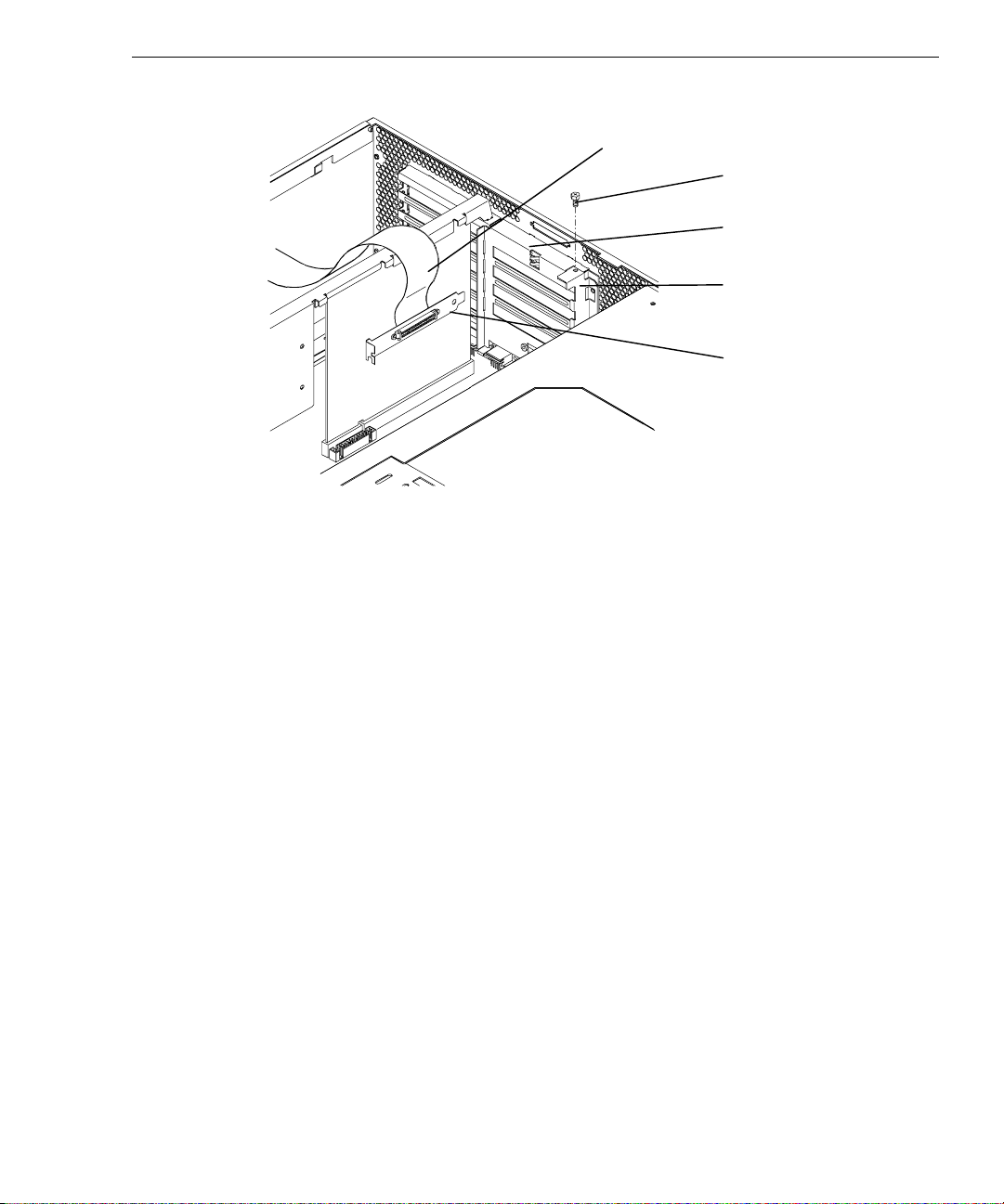
Internal Expansion Cable
Screw
ISA I/O
Slot Panel
ISA I/O Lock
Bracket
RAID Connector
Bracket
4. Remove the blanking plate from an available ISA I/O slot.
5. Install the RAID connector bracket of the internal expansion cable into the ISA I/O slot.
6. Replace the ISA I/O lock bracket.
21
7. For each additional internal expansion you want to add, refer to Chapter 1, “Getting
Started,” for PCI slot designations for your system. Install another RAID controller
board into the appropriate PCI slot, and repeat steps 1 through 6 to install another
internal expansion cable.
8. Close the system’s base unit as described in your system’s documentation.
9. Connect the disk array to the system as described in “Connecting InterRAID-8 to the
System.”
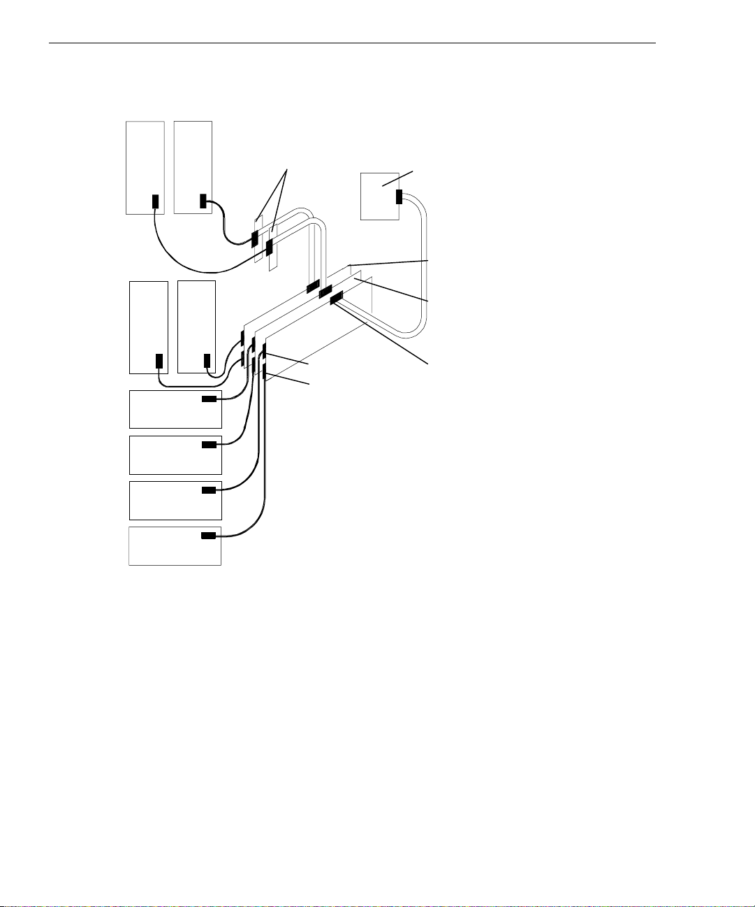
Installing Multiple Expansions
Once you understand how to expand a configuration by installing an additional RAID
controller board and an internal expansion cable, refer to the following figure to continue
expanding. The figure depicts two expansions supporting a total of nine single-channel,
deskside, disk arrays (including the internal RAID subsystem).
Page 37
22
Adding a third expansion is not shown, but is discussed later.
A B
B B
A
A
Available
ISA I/O
slot
Channel 0
Channel 1
Channels 0, 1, and 2 on the primary RAID
controller board in PCI slot 3 supports two
external disk arrays and one internal RAID
subsystem.
Internal RAID
Subsystem and
Cabling
“B” Expansion
(See Note 2.)
“A” Expansion
(See Note 1.)
Channel 2
Notes
1. Installing the “A” expansion with a secondary RAID controller board in PCI slot 2
supports three new disk arrays. Two arrays connect to the RAID controller and one
array connects to the RAID connector in the ISA I/O slot.
2. Installing the “B” expansion with a secondary RAID controller board in PCI slot 1
supports three new disk arrays. Two arrays connect to the RAID controller and one
array connects to the RAID connector in the ISA I/O slot.
Adding a third expansion to this InterRAID-8 configuration provides a maximum of four
RAID controller boards supporting twelve disk arrays (including the internal RAID
subsystem). The fourth RAID controller board will reside in either PCI slot 6 or 5,
depending on which slot is available. The third expansion will also use an available ISA I/O
slot and the RAID SCSI cable.
Page 38

Installing the RAID Disk Drives
The InterRAID-8 cabinet contains up to eight 1.0-inch or 1.6-inch high, 3.5-inch form factor
RAID disk drives. Supported capacities include 2 GB, 4 GB, 9 GB, and higher as the disk
drives become available. Contact an Intergraph sales representative for drive availability.
The left-hand side of the disk drive label identifies the disk drive size.
NOTE Intergraph attaches a SCSI ID number to the disk drive label to identify each of the boot disk
drives. All other disk drives are for data storage and do not specify a SCSI ID number.
CAUTION Ensure you install the boot disk drives into the InterRAID-8 cabinet that connects to the
primary RAID controller board.
To install the RAID disk drives:
1. Unlock the front panel door using the key for the InterRAID-8 cabinet.
2. Remove the RAID disk drives from the carton labeled, “This box contains disk drives
loaded with operating system software ...” The first three drives (ID 0, 1, 2) contain the
operating system.
The following table shows the order in which to install the boot disk drives:
23
Disk Drive Label
ADP CHN ID 2 Slot 3
ADP CHN ID 1 Slot 2
ADP CHN ID 0 Slot 1 (bottom, if deskside; right-hand, if rack)
3. Install the boot disk drives in the primary InterRAID-8 cabinet. To insert a drive,
extend the drive latching clips and slide the drive into the slot. Push between the
latching clips until the drive connects. Close the drive latching clips until they snap into
place, locking the drive into the slot. Refer to the following figure.
CAUTION Carefully insert the disk drives to avoid damaging the Single Connector Attachment (SCA)
connector.
InterRAID-8 Slots
Page 39
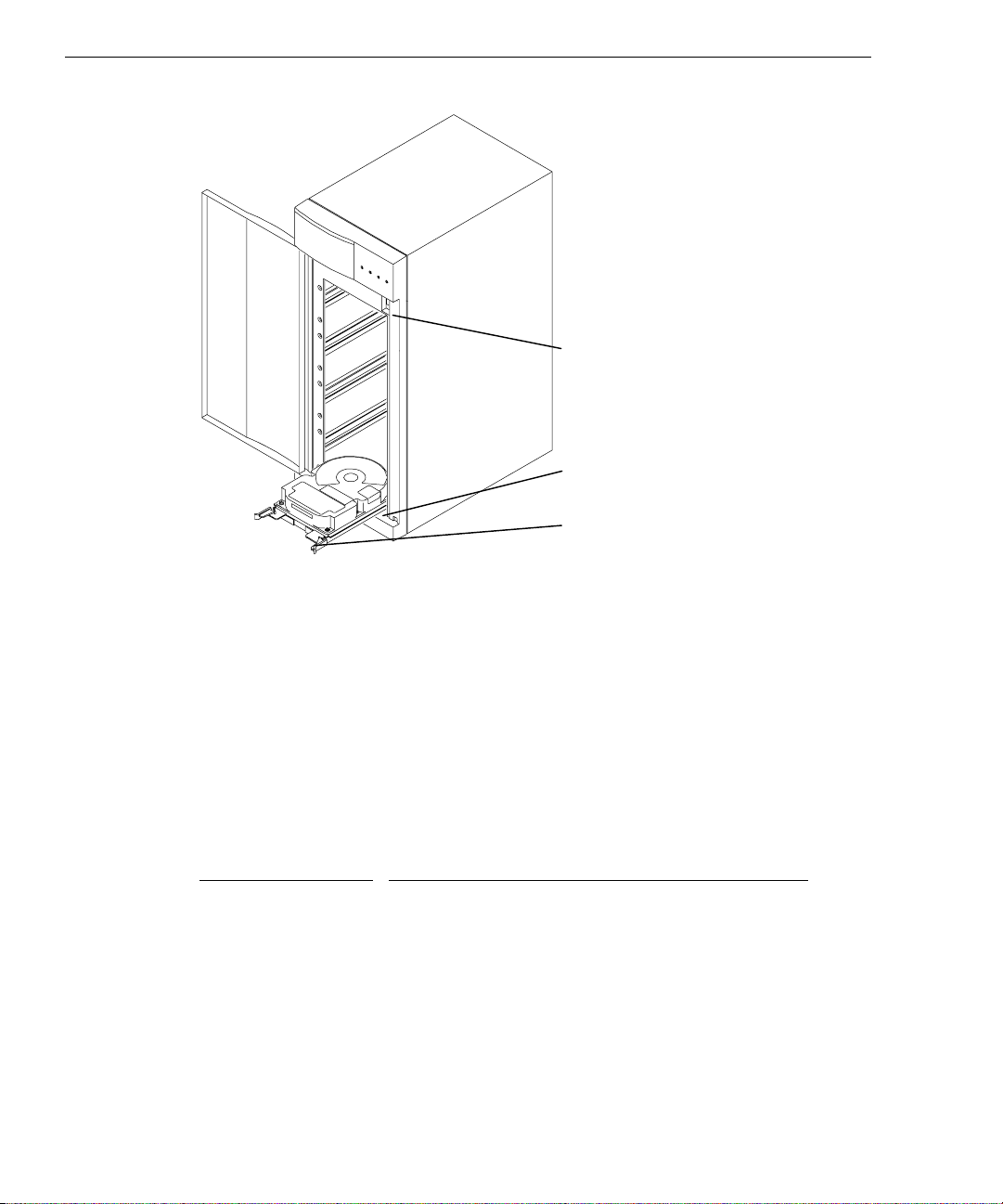
24
Power Switch
Slot 1
Drive Latching Clip (Open)
4. Install the remaining RAID disk drives without labels into the primary cabinet. You can
install them in any order as long as the slots are filled sequentially upward (for example,
do not install drives in slots 5 and 7, leaving slot 6 empty).
5. If necessary, fill in the label information for each RAID disk drive. Refer to the Drive
Labeling instruction sheet. The disk drive label has blank spaces for you to apply the
appropriate numbers to indicate the RAID controller board number (ADP X), channel
number (CHN Y), and SCSI ID number (ID Z). In the tables below, Intergraph reserves
SCSI ID 3 for the entire disk array and SCSI ID 7 for the RAID controller board. In a
single-channel InterRAID-8 cabinet, all eight RAID disk drives connect to a single
channel.
Use the following table to label the drives:
Disk Drive Label
InterRAID-8 Slots
ADP X CHN 0 ID 9 Slot 8 (top, if deskside; left-hand, if rack-mount)
ADP X CHN 0 ID 8 Slot 7
ADP X CHN 0 ID 6 Slot 6
ADP X CHN 0 ID 5 Slot 5
ADP X CHN 0 ID 4 Slot 4
ADP X CHN 0 ID 2 Slot 3
ADP X CHN 0 ID 1 Slot 2
ADP X CHN 0 ID 0 Slot 1 (bottom, if deskside; right-hand, if rack-mount)
Page 40

In a dual-channel InterRAID-8 cabinet, the lower four RAID disk drives connect to
channel 0; the upper four RAID disk drives connect to channel 1.
Use the following table to label the drives:
25
Disk Drive Label
InterRAID-8 Slots
ADP X CHN 1 ID 4 Slot 8 (top, if deskside; left-hand, if rack-mount)
ADP X CHN 1 ID 2 Slot 7
ADP X CHN 1 ID 1 Slot 6
ADP X CHN 1 ID 0 Slot 5
ADP X CHN 0 ID 4 Slot 4
ADP X CHN 0 ID 2 Slot 3
ADP X CHN 0 ID 1 Slot 2
ADP X CHN 0 ID 0 Slot 1 (bottom, if deskside; right-hand, if rack-mount)
6. If you have additional cabinets, install the disk drives and complete the drive label
information as appropriate.
Powering On and Configuring the System
To prevent accidental power off or on, the power switch is recessed and not accessible with
the door closed and locked. Before starting the system for the first time, read the following
important operating and software notices.
Important Operating Notices
u
Always power on the InterRAID-8 cabinet and wait for the audible beep before powering
on the system base unit.
u
If you turn off the power to the system base unit before completing the setup procedures,
you must reload the operating system. Once you power on the system base unit, do not
power off the system without completing Windows NT Server installation.
u
Always power off the system base unit before powering off the InterRAID-8 cabinet. If
you power off the cabinet first, the RAID controller board will read the drives as dead
the next time you power on the system. Refer to Chapter 5 “Using DAC InterRAID
Utilities,” or Chapter 6 “Using MegaRAID BIOS” and Chapter 7, “Using Power
Console.”
Important Soft ware Notices
u
You must complete the Windows NT Server installation before using the system.
Page 41

26
u
The RAID controller board has two types of write caching: write-back and writethrough. Write-through caching reduces the risk of data loss in the event of a power
failure. Write-back caching improves performance, but the drawback is potential data
loss if power fails. Intergraph recommends connection to a UPS to guard against data
loss.
u
Intergraph configures the RAID controller board to RAID level 5. RAID controllers
support RAID levels 0, 1, 5, 6 (0+1), and 7. The MegaRAID controller, in addition to
the other levels, also supports RAID level 3.
To power on and configure the system:
1. Power on the InterRAID-8 cabinet and wait for the audible beep.
2. Power on the system base unit and the monitor.
3. Complete the Windows NT Server installation. Refer to the system’s setup or
configuration documentation.
4. Install the proper software utilities available for the RAID controller board installed in
the system.
For DAC960P and DAC960PD boards, install the DACADM and DACMON utilities.
Refer to Chapter 5, “Using DAC InterRAID Utilities.”
For MegaRAID boards, install the MegaRAID BIOS and Power Console utilities. Refer
to Chapter 6, “Using MegaRAID BIOS” and Chapter 7, “Using Power Console.”
WARNING After you configure the RAID disk drives, it is very important that you backup the
configuration to a diskette. It will be very helpful for future use in the event the
configuration should become lost. Refer to Chapter 5 “Using DAC InterRAID Utilities,”
or Chapter 6 “Using MegaRAID BIOS” and Chapter 7, “Using Power Console.”
5. If necessary, configure the RAID controller board to your preferences. Refer to Chapter
5 “Using DAC InterRAID Utilities,” or Chapter 6 “Using MegaRAID BIOS” and
Chapter 7, “Using Power Console.”
6. Use Disk Administrator in Windows NT to partition and format the disk space not used
by the operating system. When prompted to create a Signature File, select Yes. Refer to
the Windows NT Server System Guide for information on using Disk Administrator.
Page 42

4 Setting Up and Expanding
InterRAID-12
To set up the InterRAID-12 disk array with a system base unit, you will perform the
following tasks:
u
Connect the InterRAID-12 cabinet to the system base unit.
u
Expand the system (if installing additional disk arrays).
u
Install the RAID disk drives.
u
Power on and configure the system.
Connecting InterRAID-12 to the System
When setting up the InterRAID-12 cabinet in a vertical position, first install the plastic feet
on the cabinet according to the Feet Installation instruction sheet. If setting up the cabinet
horizontally, install the rubber pads on the cabinet in the recessed area of each corner.
27
To connect the InterRAID-12 cabinet:
1. Connect a RAID SCSI cable to the channel 0 port on the RAID controller in the base
unit, and to the channel 0 port on the InterRAID-12 cabinet.
Channel 1
RAID
Controller
Board in Base
Unit
Channel 0
Page 43

28
2. Connect a RAID SCSI cable to the channel 1 port on the RAID controller board in the
base unit, and to the channel 1 port on the InterRAID-12 cabinet.
Connecting Remaining Cabinets and Cables
To connect the remaining cabinets and cables:
1. Choose the proper power cord for the cabinet. Refer to the Power Supply Cord Selection
instruction sheet included in the accessory pack.
2. Connect the power cord to the InterRAID-12 cabinet.
3. Connect the other end of the power cord to an Uninterruptible Power Supply (UPS), if
available, or to a grounded, three-prong AC power outlet.
CAUTION If the system does not connect to a UPS, data loss can occur if there is a power failure.
4. If you have additional cabinets, connect the RAID SCSI cables and power cords in the
same manner as instructed above.
5. Use the following table as a guide to install any secondary RAID controller boards.
Number of
RAID
Controllers
One PCI Slot 3 - - Two PCI Slot 3 PCI Slot 2 - Three PCI Slot 3 PCI Slot 2 PCI Slot 1 Four PCI Slot 3 PCI Slot 2 PCI Slot 1 PCI Slot 6
−
If PCI Slot 6 is not available, use PCI Slot 5.
−
For Intergraph deskside systems with internal RAID, the internal RAID subsystem
already contains the boot drives. The primary RAID controller board connects to
the internal RAID subsystem.
−
For Intergraph deskside systems with an internal hard disk drive, the boot drive is
the internal hard disk drive and does not require connection to a primary RAID
controller board. Any external cabinets and associated RAID controller boards are
secondary.
Primary Secondary Secondary Secondary
Page 44

Expanding the System
This section provides instructions to expand your InterServe 6x system or InterServe 6xx
system with additional InterRAID-12 disk arrays. The following describes unpacking,
placing cabinets, setting up, and connecting the InterRAID-12 Expansion Solution to your
system.
Unpacking
Carefully unpack the InterRAID-12 Expansion Solution equipment, and verify that you have
the following items:
u
InterRAID-12 cabinet
u
Key for cabinet door
u
RAID disk drives
u
Diskettes containing configuration and utility software
u
Documentation
u
Antistatic wrist strap
29
u
Accessory pack containing a power cord, RAID SCSI cables, four plastic feet, eight cap
head screws, one hex wrench, disk drive labels, rubber pads, a blanking plate, a Drive
Labeling sheet, a Feet Installation sheet, a Power Supply Cord Selection sheet, and an
Antistatic Handling sheet
The Expansion Solution equipment may also include a RAID controller board.
CAUTION Do not remove the RAID disk drives from the antistatic bags until you are ready to install the
drives in the cabinet. Do not handle the RAID disk drives unless you connect an antistatic
wrist strap to your wrist and to a bare metal surface on the cabinet.
Retain all packaging materials. You must return the system in the original packaging to
obtain warranty service. Refer to the instructions in the back of this guide for returning
equipment to Intergraph.
Placi ng Cabinets
To place the cabinets side-by-side:
1. Place the feet on the bottom of the cabinet as described in the Feet Installation sheet.
2. Set the cabinet a few inches away from the existing cabinets.
Page 45

30
To stack the cabinets:
1. If existing InterRAID cabinets are not already stacked, remove the RAID disk drives
from them and place the drives on an antistatic surface.
CAUTION Keep track of the drive locations. You must install the drives in the same cabinets and slots
from which you remove them.
2. To rotate the Information Control Panel on the cabinet door, open the cabinet door and
remove the folded section of ribbon cable from the slit in the Mylar on the back of the
door.
3. Using a 5/16-inch nutdriver, remove the hex nuts from the corners of the Information
Control Panel.
4. Rotate the Information Control Panel one-quarter turn counterclockwise and re-attach it
to the door with the hex nuts. Do not overtighten the nuts.
5. Close the cabinet door.
6. Place the rubber pads from the accessory pack into the recessed locations on the left side
(as viewed from the front) of the cabinet.
7. Place the bottom cabinet on its rubber pads on a flat, hard surface (not on carpet).
8. For each additional InterRAID cabinet you want to stack, repeat steps 2 through 6 and
place the additional cabinet on top of the previous cabinet.
CAUTION You may stack up to four InterRAID cabinets in a single stack.
9. If you removed RAID disk drives from existing InterRAID cabinets, replace them.
Setting Up Host
The following provides instructions for setting up the host system for use with an
InterRAID-12 Expansion Solution RAID controller board.
To setup the host for use with InterRAID-12:
1. If your Expansion Solution came with a RAID controller board, install it into the
appropriate PCI slot in the system’s base unit. Refer to Chapter 1, “Getting Started,” for
PCI slot designations. Refer to your system’s documentation for instructions on opening
the base unit, taking precautions against electrostatic discharge, and installing option
boards.
−
On InterServe 6x systems, the primary RAID controller is installed in PCI slot 3.
Install additional (secondary) controllers in PCI slots 4, 5, and 6.
Page 46

−
On InterServe 6xx systems, the primary RAID controller is installed in PCI slot 3.
Install additional (secondary) controllers in PCI slots 2, 1, and 6 (in that order). If
PCI slot 6 is not available, use PCI slot 5.
−
For Intergraph deskside systems with internal RAID, the internal RAID subsystem
already contains the boot disk drives. The primary RAID controller connects to the
internal RAID subsystem.
−
For Intergraph deskside systems with an internal hard disk drive, the internal hard
disk drive is the boot disk drive and does not require connection to a primary RAID
controller. Any external disk arrays and associated RAID controllers are secondary.
2. For stacked cabinets, route the RAID SCSI cables and power cables through the cable
guides on the back of each cabinet.
Installing the RAID Disk Drives
The InterRAID-12 cabinet contains up to twelve 1.0-inch high, 3.5-inch form factor RAID
disk drives. Supported capacities include 1 GB, 2 GB, 4 GB, and higher as the disk drives
become available. Contact an Intergraph sales representative for drive availability. The lefthand side of the disk drive label identifies the disk drive size.
31
NOTE Intergraph attaches a SCSI ID number to the disk drive label to identify each of the boot disk
drives. All other disk drives are for data storage and do not specify a SCSI ID number.
CAUTION Ensure you install the boot disk drives into the InterRAID-12 cabinet that connects to the
primary RAID controller board.
To install the RAID disk drives:
1. Unlock the front panel door using the key for the InterRAID-12 cabinet.
2. Remove the RAID disk drives from the carton labeled, “This box contains disk drives
loaded with operating system software ...” The first three drives (ID 0, 1, 2) contain the
operating system.
The following table shows the order in which to install the boot disk drives:
Disk Drive Label
ADP CHN ID 2 Slot 3
ADP CHN ID 1 Slot 2
ADP CHN ID 0 Slot 1 (Bottom)
InterRAID-12 Slots
Page 47

32
3. Install the boot disk drives in the primary InterRAID-12 cabinet. To insert a drive,
extend the drive latching clips and slide the drive into the slot. Push between the
latching clips until the drive connects. Close the drive latching clips until they snap into
place, locking the drive into the slot. Refer to the following figure.
CAUTION Carefully insert the disk drives to avoid damaging the Single Connector Attachment (SCA)
connector.
Power Switch
Slot 12
Drive Latching
Clip (Open)
Slot 1
4. Install the remaining RAID disk drives without labels into the primary cabinet. You can
install them in any order as long as the slots are filled sequentially upward (for example,
do not install drives in slots 5 and 7, leaving slot 6 empty).
If necessary, fill in the label information for each RAID disk drive. Refer to the Drive
Labeling instruction sheet. The disk drive label has blank spaces for you to apply the
appropriate numbers to indicate the RAID controller board number (ADP X), channel
number (CHN Y), and SCSI ID number (ID Z). In the table below, Intergraph reserves
SCSI ID 3 for the entire disk array. The lower six RAID disk drives connect to channel
0, and the upper six RAID disk drives connect to channel 1.
Page 48

Use the following table to label the drives:
33
Disk Drive Label
InterRAID-12 Slots
ADP X CHN 1 ID 6 Slot 12 (Top)
ADP X CHN 1 ID 5 Slot 11
ADP X CHN 1 ID 4 Slot 10
ADP X CHN 1 ID 2 Slot 9
ADP X CHN 1 ID 1 Slot 8
ADP X CHN 1 ID 0 Slot 7
ADP X CHN 0 ID 6 Slot 6
ADP X CHN 0 ID 5 Slot 5
ADP X CHN 0 ID 4 Slot 4
ADP X CHN 0 ID 2 Slot 3
ADP X CHN 0 ID 1 Slot 2
ADP X CHN 0 ID 0 Slot 1 (Bottom)
6. If you have additional cabinets, install the RAID disk drives and complete the drive
label information as appropriate.
Powering On and Configuring the System
To prevent accidental power off or on, the power switch is recessed and not accessible with
the door closed and locked. Before starting the system for the first time, read the following
important operating and software notices.
Important Operating Notices
u
Always power on the InterRAID-12 cabinet and wait for the audible beep before
powering on the system base unit.
u
If you turn off the power to the system base unit before completing the setup procedures,
you must reload the operating system. Once you power on the system base unit, do not
power off the system without completing Windows NT Server installation.
u
Always power off the system base unit before powering off the InterRAID-12 cabinet. If
you power off the cabinet first, the RAID controller board will read the drives as dead
the next time you power on the system. Refer to Chapter 5 “Using DAC InterRAID
Utilities,” or Chapter 6 “Using MegaRAID BIOS” and Chapter 7, “Using Power
Console.”
Page 49

34
Important Soft ware Notices
u
You must complete the Windows NT Server installation before using the system.
u
The RAID controller board has two types of write caching: write-back and writethrough. Write-through caching reduces the risk of data loss in the event of a power
failure. Write-back caching improves performance, but the drawback is potential data
loss if power is interrupted. Intergraph recommends connection to a UPS to guard
against data loss.
u
Intergraph configures the RAID controller board to RAID level 5. RAID controllers
support RAID levels 0, 1, 5, 6 (0+1), and 7. The MegaRAID controller, in addition to
the other levels, also supports RAID level 3.
To power on and configure the system:
1. Power on the InterRAID-12 cabinet and wait for the audible beep.
2. Power on the system base unit and the monitor.
3. Complete the Windows NT Server installation. Refer to the system’s setup or
configuration documentation.
4. Install the proper software utilities available for the RAID controller board installed in
the system.
For DAC960P and DAC960PD boards, install the DACADM and DACMON utilities.
Refer to Chapter 5, “Using DAC InterRAID Utilities.”
For MegaRAID boards, install the MegaRAID BIOS and Power Console utilities. Refer
to Chapter 6, “Using MegaRAID BIOS” and Chapter 7, “Using Power Console.”
WARNING After you configure the RAID disk drives, it is very important that you backup the
configuration to a diskette. It will be very helpful for future use in the event the
configuration should become lost. Refer to Chapter 5 “Using DAC InterRAID Utilities,”
or Chapter 6 “Using MegaRAID BIOS” and Chapter 7, “Using Power Console.”
5. If necessary, configure the RAID controller board to your preferences. Refer to Chapter
5 “Using DAC InterRAID Utilities,” or Chapter 6 “Using MegaRAID BIOS” and
Chapter 7, “Using Power Console.”
6. Use Disk Administrator in Windows NT to partition and format the disk space not used
by the operating system. When prompted to create a Signature File, select Yes. Refer to
the Windows NT Server System Guide for information on using Disk Administrator.
Page 50

5 Using DAC InterRAID Utilities
This chapter pertains only to systems containing either the DAC960P or DAC960PD
controller. If your system contains the MegaRAID controller, refer to Chapter 6.
NOTE Chapter 1 describes how to determine which RAID controller shipped with your system.
This chapter describes how to upgrade the DAC960 driver and use the RAID Basic
Input/Output System (BIOS) and all of the DAC960 Configuration Utility (DACCF) options.
The “Common DACCF Procedures” section contains procedures such as enabling automatic
rebuild, changing the write policy, configuring additional disk arrays, and recovering
unusable (DED) disk drives.
Intergraph includes DACCF on a diskette delivered with the InterRAID cabinets. Other
available utilities include the Disk Array Controller Administrator (DACADM) and the Disk
Array Controller Monitor (DACMON).
NOTE If you need to load the new driver, follow the applicable instructions in the following section
for Windows NT 3.51 or Windows NT 4.00. The DAC960 driver resides on the same diskette
containing DACCF.
35
Updating the DAC960 Driver
The DAC960 driver provides an interface for administering the InterRAID disk array
products. After configuring the Windows NT operating system, you must install the updated
Intergraph DAC960 driver.
To install the updated DAC960 driver for use with Windows NT 3.51:
1. Boot the system and log in as administrator.
2. At Program Manager, open Windows NT Setup.
3. From the Options menu, select Add/Remove SCSI Adapters.
4. Select the DAC960 driver; then, select Remove.
5. Select OK at the Warning dialog; then, select OK again.
6. At the Warning dialog, select Add; then, select OK. Windows NT Setup displays a list
of adapters.
7. Scroll to OTHER (Requires disk from a hardware manufacturer).
Page 51

36
8. Insert the diskette containing DAC960 NT driver into the floppy disk drive, and select
OK. The Select OEM Option dialog displays with the DAC960 adapter highlighted.
9. Select OK. Setup displays the Select SCSI Adapter Option dialog.
10. Select Install. Setup displays a message that the driver is already present on the system.
11. Select New; then, select Continue at the prompt to specify the path to the adapter files.
12. At the SCSI Adapter Menu, select Close.
13. From the Options menu, select Exit.
14. Reboot the system.
To install the updated DAC960 driver for use with Windows NT 4.00:
1. Boot the system and log in as administrator.
2. Open Control Panel.
3. Select SCSI Adapters icon.
4. Click the Drivers tab.
5. Select the DAC960 driver.
6. Click Remove to remove the old driver.
7. Click the Drivers tab again.
8. Click Add.
9. Click Have Disk.
10. Follow the instruction on the screen to install the updated driver.
11. Remove the diskette containing the DAC960 driver from the disk drive.
12. Reboot the system.
DACADM and DACMON Utilities
Two DAC960 administrative utilities are easy to install and use in the Windows NT
environment. The DACADM utility is the main administrative utility for the RAID
controller board and its attached disk arrays. The DACMON utility monitors the status of
the RAID controller board by recording all abnormal activities in the Event Viewer.
Page 52

The following Windows NT 3.5x and 4.00 drivers and utilities are provided in the DAC960
disk array driver and utilities:
DAC960NT.SYS Main DAC960 driver file for Windows NT
DACADM.EXE RAID controller board administration utility
DACMON.EXE Utility for monitoring the RAID controller board
To install DACADM and DACMON utilities:
1. Insert the diskette containing the DAC960 disk array driver and utilities into the floppy
disk drive.
2. Copy the DACADM and DACMON files to the SystemRoot\SYSTEM32 directory.
3. At the command prompt, key in the following (if Windows NT 4.00, use the Run
command):
a:\srvccfg dacmon DAC960Monitor c:\winnt\system32\dacmon.exe
In the above command, it is assumed that the Windows NT system files have been
copied in the directory named \WINNT. You can modify this command as appropriate.
37
Starting DACADM
Before running DACADM under Windows NT 3.51, create an icon in the Administrative
Tools program group.
To create an icon, and start DACADM using Windows NT 3.51:
1. Open Administrative Tools.
2. From File menu in Program Manager, select New. The dialog displays.
3. Select Program Item. The dialog displays.
4. In the Description box, type dacadm.
5. In the Command Line box, type dacadm.
6. Select OK. The dialog closes and the new icon appears in the group.
7. Double-click the DACADM icon in the Administrative Tools program group to execute
the utility.
Page 53

38
Before running DACADM under Windows NT 4.00, create an icon in the Program group.
To create an icon, and start DACADM using Windows NT 4.00:
1. Select Start => Settings => Taskbar
2. Click Start Menu Programs.
3. Click Add.
4. In the Command Line box, type c:\winnt40\system32\dacadm.exe.
5. Click Next; then click Finish. The dialog closes and the new icon appears in the group.
6. To execute the utility, select Start => Programs; then, click the DACADM icon.
DACADM Options
Under the Options pull-down menu, you will find the following entries:
u
Select Adapter
u
Drive Information
u
Change/Add Device
u
Make Standby
u
Rebuild Drive
u
System Drive
Select Adapter and System Drive have their own unique dialogs, whereas the Device
Selection dialog is common for all of the other entries.
The Device Selection dialog shows a matrix of the drives connected to the various channels
of the selected RAID controller board. The left-most column of the corresponds to SCSI ID
0. The SCSI ID increments by one number for each column. The letters STBY, DEAD, and
ONLN indicate standby, dead, and online. During rebuild, a box with dashes indicates the
rebuild process is occurring. A blank box indicates that a disk drive was not found for that
channel location and SCSI ID.
NOTE SCSI ID3 is blank to indicate it is reserved for the entire disk array.
Select Adapter
Use Select Adapter to select the RAID controller board for information or to perform an
action. The available DAC960 controller boards on the system are displayed as Adapter 1,
Adapter 2, etc. in the small boxes.
Page 54

Commands are executed only on the selected board. If a RAID controller board is not found,
the message “Not Installed” appears in the box.
Drive Information
Use this option to provide information about the disk drives connected to the selected RAID
controller board in a system. The horizontal bar represents the SCSI channel and the box
represents a drive. The box also indicates the drive status. Select a drive to view
information on soft error, hard error, parity error, drive model, or select OK to exit.
Change/Add Device
Use this option to idle a SCSI channel on the RAID controller board. Use this function when
replacing or rebuilding a dead drive on the selected channel. After the channel idles,
disconnect and remove the dead drive. Install a drive that functions properly.
NOTE Activity on the SCSI channel restarts 30 seconds after you idle a channel without informing
you with a message. Changing a drive must be done in less than 30 seconds, or done in two
stages: Idle the channel before removing the dead drive, then idle the channel again before
installing the new drive.
39
Make Standby
Use this option to create a standby drive. Select the dead (DEAD) drive box to make the
dead drive a standby drive. The RAID controller board will automatically try to start the
drive. If successful, it will make the drive a standby drive.
NOTE Only drives that are not part of any Drive Group (pack) can be made standby drives.
Rebuild Drive
Use this option to rebuild a drive indicated as dead by the RAID controller board. Before
executing this option, replace the dead drive with a properly working drive. Select the dead
(DEAD) drive box to start a rebuild on the drive selected, or select OK to exit. After the
rebuild starts, the rebuild status displays every system drive that needs the rebuild process.
System Drive
Use this option to display complete information about the system drives connected to the
RAID controller board. The information displayed includes the system drive number, RAID
level, write policy size, and status. The System Drive option also indicates system drives
that are Online, Offline or in a Critical state.
Page 55

40
DACMON Overview
The DACMON utility monitors the activities of the RAID controller board in the system and
records the activities in the Event Viewer. DACMON will fail to run if the RAID controller
board is not present. DACMON displays the status of the RAID controller board, the disk
drives, and the progress of any rebuild operations.
Starting DACMON
The DACMON icon must be included in Startup for activation under the Windows NT
operating system.
To create a DACMON icon:
1. Open Startup.
2. From File menu in Program Manager, select New. The dialog displays.
3. Select Program Item. The dialog displays.
4. In the Description box, type dacmon.
5. In the Command Line box, type dacmon.
6. Select OK. The dialog closes. The next time the system reboots, the minimized
DACMON icon appears in the lower left corner of the display.
To view output from the Event Viewer:
1. Under Administrative Tools, select Event Viewer.
2. At Log, select Application. The messages appear concerning the activities of the RAID
controller board and the time of the event.
RAID BIOS Setup
The RAID controller board contains its own BIOS separate from the system BIOS. Refer to
the system’s hardware documentation for information regarding the system BIOS for the
host server.
NOTE The DAC960P and DAC960PD boards use the same BIOS.
Page 56

Startup Sequence
During power up, the RAID controller board’s BIOS displays a sign-on message with its
version number and date. The sign-on message looks similar to the following:
DAC960P(D) BIOS Version x.xx--
Thereafter, the BIOS tries to locate the RAID disk array controller. Once located, the BIOS
determines if the controller firmware is operational. The RAID BIOS also looks for any
initialization error message that may be posted by the controller firmware. If it finds a
message, it displays one of the following errors on the screen and aborts the installation
process.
DAC960 fatal error--memory test failed
DAC960 fatal error--command interface test failed
DAC960 hardware error--run diagnostics to pinpoint error
DAC960 firmware checksum error--reload firmware
If any of these messages displays, call the Customer Response Center at
1-800-633-7248 for assistance.
41
Error Conditions While Checking the Drives
If the firmware finds a valid DAC960 configuration, but it does not match the SCSI drives
currently installed, one or more of the following messages display:
Unidentified device found at channel x....
Device identified for chn x, tgt y found at chn x’, tgt y’
SCSI device at chn x, tgt y not responding
If any of the above messages displays, the firmware stops the initialization process, except to
find other mismatches. Then, the BIOS displays the following:
DAC960 Configuration Checksum error-run configuration utility
Mismatch between NVRAM and Flash EEPROM configuration
At the next stage the following message may appear:
Recovery from mirror race in progress
The above message displays if the firmware detects that the system powered off abruptly,
letting some incomplete write operations occur.
The following messages may also appear:
Page 57

42
Adapter cannot recover from mirror race!
Some system drives are inconsistent!
If the firmware fails to respond to the BIOS inquiry within two minutes, the following
message displays:
DAC960 not responding--no drives installed.
The BIOS then inquires for the firmware version and other information, and displays the
following message:
DAC960 firmware version x.xx
One or more of the following messages display if the firmware reports the error conditions:
Warning: X system drives are offline
Warning: X system drives are critical
Warning: The following SCSI devices are dead--chn x, tgt y...
No system drives found: None installed
X system drives installed
The BIOS repeats the same process for additional DAC960 controllers present in the system.
Then, when possible, it proceeds to boot from the first system drive on the primary RAID
controller board.
Overview of DACCF
To use DACCF, you should be familiar with MS-DOS and understand the basic terminology
associated with RAID. Refer to Chapter 10 and the glossary for basic information about
RAID concepts and terminology.
The non-volatile memory and flash EEPROM on the RAID controller board stores the
DACCF configuration data. When you restart the system, the RAID controller (DAC960P
or DAC960PD) uses this information to define the RAID configuration to the operating
system.
Throughout the utility, a banner at the top of the display shows the title, version number,
date, controller name, slot number, and firmware version. At the bottom of every display,
DACCF indicates the actions you can take for each menu option. Additionally, information
boxes describe possible actions not allowed. Warning boxes display when the next action
could destroy data on the drives, erase configurations, or has other serious system
consequences.
Page 58

The following table defines the terms you will see while running DACCF and configuring
drives.
RDY Disk drive ready for configuration
CDR CD-ROM drive
TAP Tape drive
UNF Unformatted drive
PAK Configured packs
DRVS Number of drives in a pack
SIZE Size of the packs (in megabytes)
ONL Drive online (part of pack)
DED Failed drive
RBD Rebuilding
WRO Rebuilding (write only)
FMT Formatting
SBY Standby drive
43
Starting DACCF
You must run DACCF from a diskette. The boot sequence of the system must be A:, C:. If it
is not, refer to the system’s hardware documentation for instructions to change the boot
sequence.
To start the DACCF utility:
1. Insert the DACCF diskette into the floppy disk drive, and then restart the system.
2. At the command prompt, execute DACCF by keying in daccf.
DACCF detects the drives connected to the RAID controller board. A display similar to
the following appears.
Page 59
44
MYLEX Disk Array Controller-Configuration Utility Version X.XX X/XX/XX
Inqu iring the devic es co nnec ted t o the adap ter
Cha nnel # X Targ et ID X
Ini tializing table s, pl ease wait ...
The DACCF Main Menu displays if there is only one board installed, as described in the
“Main Menu” section. If you have multiple RAID boards in the system, refer to step 3
following. If error messages display, refer to “Error Conditions” in this chapter.
3. If the system contains more than one RAID controller board, a menu similar to the
following lists them according to the BIOS scan order.
MYLEX Disk Array Controller-Configuration Utility Version X.XX X/XX/XX
2 Channel - 7 Target DAC960P #1 Firmware version x.xx
Select DAC9 60
DAC960P (PC I) #1
DAC960P (PC I) #2
DAC960P (PC I) #3
DAC960P (PC I) #4
Select DAC960 using cursor keys, hit <Enter>, <ESC> to Exit
NOTE The primary RAID controller board connects to the disk array that contains the boot disk
drives. The primary RAID controller board always precedes any secondary RAID controller
board(s) according to the scan order.
Page 60

For DTP Server and TD-xx deskside systems, the following table identifies the scan
order of the PCI slots containing the primary and secondary RAID controller boards
(DAC960).
45
DACCF DAC960
Selection Menu
- - Slot 4 1
DAC960 #1 Primary Slot 3 2
DAC960 #2 Secondary Slot 2 3
DAC960 #3 Secondary Slot 1 4
DAC960 #4 Secondary Slot 6 6
- - Slot 5 7
NOTE The BIOS scans the secondary SCSI bus fifth, and the primary SCSI bus eighth in the above
scan order.
4. Use the up and down arrow keys to highlight the RAID controller board to be
configured, and then press
a time.
NOTE If you use the default configurations outlined in this chapter, the RAID controller board
displayed as controller #1 should always connect to the disk array containing the boot disk
drives.
RAID Controller
Board
ENTER. You can configure only one RAID controller board at
System PCI Slot Scan Order
Main Menu
After successful drive initialization, the DACCF Main Menu displays.
Page 61

46
MYLEX Disk Array Controller-Configuration Utility Version X.XX X/XX/XX
2 Channel - 7 Target DAC960P #1 Firmware version x.xx
Main Menu
01. Automatic Configura tion
02. New Confi guration
03. View/Upda te Configu ratio n
04. Rebuild
05. Initializ e System D rive
06. Consisten cy Check
07. Tools
08. Select DA C960
09. Advanced Functions
10. Diagnosti cs
If more than 3 Physical Driv es ar e pre sent , choose t his
option to cre ate one RA ID 5 Syste m Dri ve a utomatical ly.
Use cursor keys for selection, hit <ENTER> to select, <ESC> to Quit
The help window (box below the Main Menu) briefly describes the operations you can
perform with the highlighted option.
Use the cursor keys to select the options in the Main Menu. Press
highlighted option. The following sections describe each option in detail.
01. Automatic Configuration
Use the Automatic Configuration option in the DACCF Main Menu only when three to eight
disk drives of the same capacity are attached to the RAID controller; the drives can be in
different disk arrays. This function aborts after displaying an error message if the drive
capacities are different.
Automatic Configuration creates a single pack using all of the drives, and then creates a
single RAID Level 5 system drive when you select the write policy for the system drive. The
system disk drive number is 0. You can define a maximum of eight (8) system drives per
DAC960 RAID controller.
To perform automatic configuration:
1. From the DACCF Main Menu, select Automatic Configuration. If a valid configuration
exists, a warning message displays:
A valid configuration exists. Proceeding further will destroy
this configuration.
ENTER to select the
Page 62

2. Select YES in the confirmation window to proceed. Select NO to return to the Main
Menu.
After selecting YES, the RAID controller examines the total capacity of each drive
connected to the controller. If all the drives are the same, this message displays:
Do you want to have Write Caching enabled?
3. Selecting YES sets the write policy to Write-back. Selecting NO sets the write policy to
Write-through. Write-through caching is required when re-installing the operating
system (the installation will fail if set to Write-back). After an installation, you can reset
it to Write-back.
CAUTION Write-through caching reduces the risk of data loss in the event of a power failure. Write-
back caching improves performance, but the drawback is potential data loss during a power
failure. Without a UPS, a power failure can corrupt a disk drive resulting in lost data.
After the system saves the configuration, a display similar to the following appears. The
display describes the configuration created.
MYLEX Disk Array Controller-Configuration Utility Version X.XX X/XX/XX
2 Channel - 7 Target DAC960P #1 Firmware version x.xx
Automatic Conf iguration
47
Number of Sys tem Drives = 1
RAID Level = 5
Write Cache = Disabled
Number of Physical Drives = 3
Available Capacity = 2026 MB
Automatic Configuration successfully done.
Make sure to INITIALIZE System drive#0 before exiting this utility!
Press any k ey to retu rn to Main Men u
4. Press any key to return to the DACCF Main Menu.
5. From the DACCF Main Menu, select Tools. Back up and print the configuration file
using the Backup/Restore Conf and the Print Configuration options of the Tools menu.
Refer to “07. Tools” in this chapter for details.
6. From the DACCF Main Menu, select Initialize System Drive to initialize the system
disk drive that does not contain the operating system. Refer to "05. Initialize System
Drive" in this chapter for details.
Page 63

48
7. To partition the disk drive space, reboot the system into Windows NT and run Disk
Administrator.
02. New Configuration
Use the New Configuration option in the DACCF Main Menu to configure the drives in the
disk array for the first time, or to establish a new configuration. This option overwrites the
existing configuration with the new configuration. When you select New Configuration, the
following menu displays.
MYLEX Disk Array Controller-Configuration Utility Version X.XX X/XX/XX
2 Channel - 7 Target DAC960P #1 Firmware version x.xx
Choose this o ption to c reate , arr ange, or cancel one or
more packs an d also to view infor matio n on the physi cal
drives connec ted to the adap ter.
New Configu ration
1. Define Pa ck
2. Define Sy stem Drive
Use Cursor keys for selection, hit <ENTER> to select, <ESC> to Exit
NOTE Use New Configuration with caution, or you will lose an existing configuration.
Define Pack
Use Define Pack in the New Configuration menu to set up physical drives into packs, cancel
and arrange existing packs. When you select Define Pack, a display similar to the following
appears.
Page 64
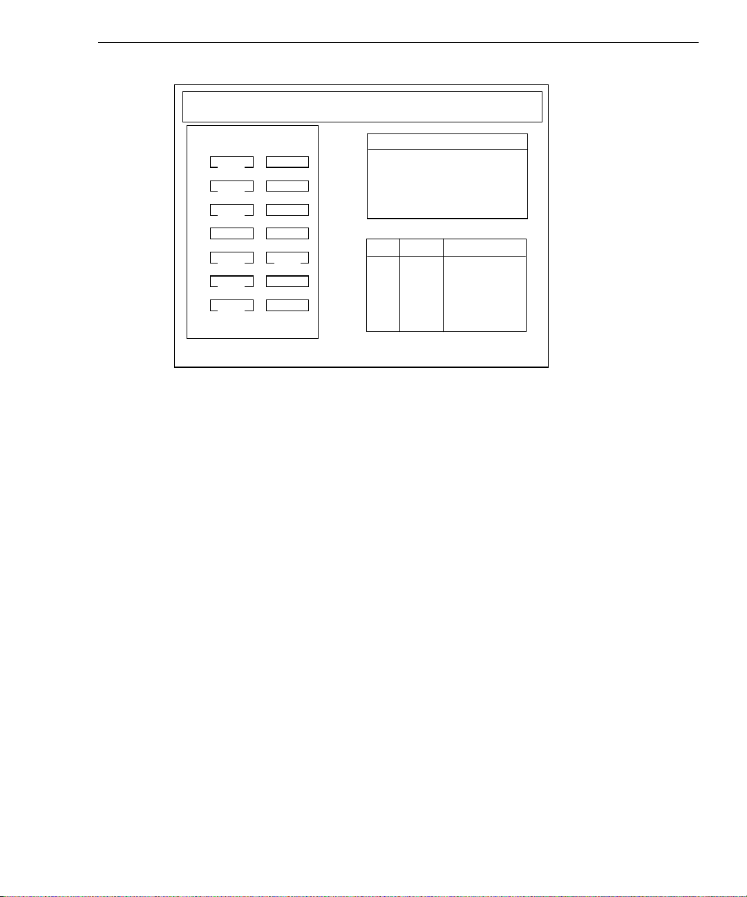
MYLEX Disk Array Controller-Configuration Utility Version X.XX X/XX/XX
2 Channel - 7 Target DAC960P #1 Firmware version x.xx
Tgt Chann el Nu mbe r
ID 0 1
0
RDY
1
RDY
2
RDY
3
4
RDY
5
RDY
6
RDY
CDR
Pack Definition
1. Create Pac k
2. Cancel Pac k
3. Arrange Pa ck
4. Device Inf ormation
PAK DRVS SIZE (MB)
The disk drive list to the left of the display contains the details of existing configured drives.
RDY indicates the disk drive is ready for configuration. CDR represents the CD-ROM
drive, and TAP represents a tape drive, if installed.
49
NOTE An unformatted (UNF) drive must be low-level formatted before configuration. Refer to “07.
Tools” in this chapter and use the Tools option of the DACCF Main Menu to low-level format
the drive.
On the lower right side of the display, columns list the configured packs (PAK), number of
drives in the packs (DRVS), and the size of the packs (SIZE) in megabytes.
Pack Definition contains four options you can select. The following instructions describe
how to use each option.
Create Pack allows you to create multiple packs containing multiple drives.
To create a pack:
1. From the Pack Definition menu, select Create Pack. The first drive in the disk array
highlights.
2. Use the up and down arrow keys to select a drive, and press
ENTER to include the drive
in the new pack.
3. Select additional drives to include in the pack.
NOTE All the drives in a pack must be the same capacity, or the pack capacity will be a multiple of
the smallest drive. To determine the capacity of a drive, refer to the instructions in this
section for displaying device information.
Page 65

50
4. When you have included all of the desired disk drives for this pack, press ESC to return
to the Pack Definition menu. The drives in the pack are labeled online (ONL), and
identified by the pack label and stripe order. For example, A-0 stands for pack A, drive
0; B-3 stands for pack B, drive 3.
If you do not want to create another pack, then the new pack must be arranged before
defining a system drive. Refer to the instructions in this section for arranging packs.
5. Repeat steps 1 through 4 to create another pack. When you have defined all drives on a
channel in a pack, the Arrange Pack option in the Pack Definition menu automatically
highlights. Refer to the instructions in this section for arranging packs.
Cancel Pack in the Pack Definition menu allows you to cancel a pack.
To cancel a pack:
1. From the Pack Definition menu, select Cancel Pack. The first drive in the first pack
highlights.
NOTE You have to cancel the packs in reverse order from the way in which you created them.
2. Press ENTER to cancel the highlighted pack, or move the cursor to another pack, and
then press
ENTER. The pack is canceled and the Cancel Pack option highlights in the
Pack Definition menu.
3. Select another pack to cancel, or choose another option in the Pack Definition menu.
Arrange Pack in the Pack Definition menu allows you to identify packs to be defined as
system drives. You cannot define a pack as a system drive until it has been arranged.
To arrange a pack:
NOTE Drives in an arranged pack that have not been configured as a system drive will be
automatically configured as standby (SBY) drives.
1. From the Pack Definition menu, select Arrange Pack. The first drive in the first pack
highlights.
2. Press
ENTER to arrange the pack. The pack information columns list the configured
packs (PAK), number of drives in the packs (DRVS), and the size of the packs (SIZE).
3. Select another pack to arrange and press
ENTER. The pack information columns update
each time you arrange a pack. The following example is for two arranged packs.
Page 66
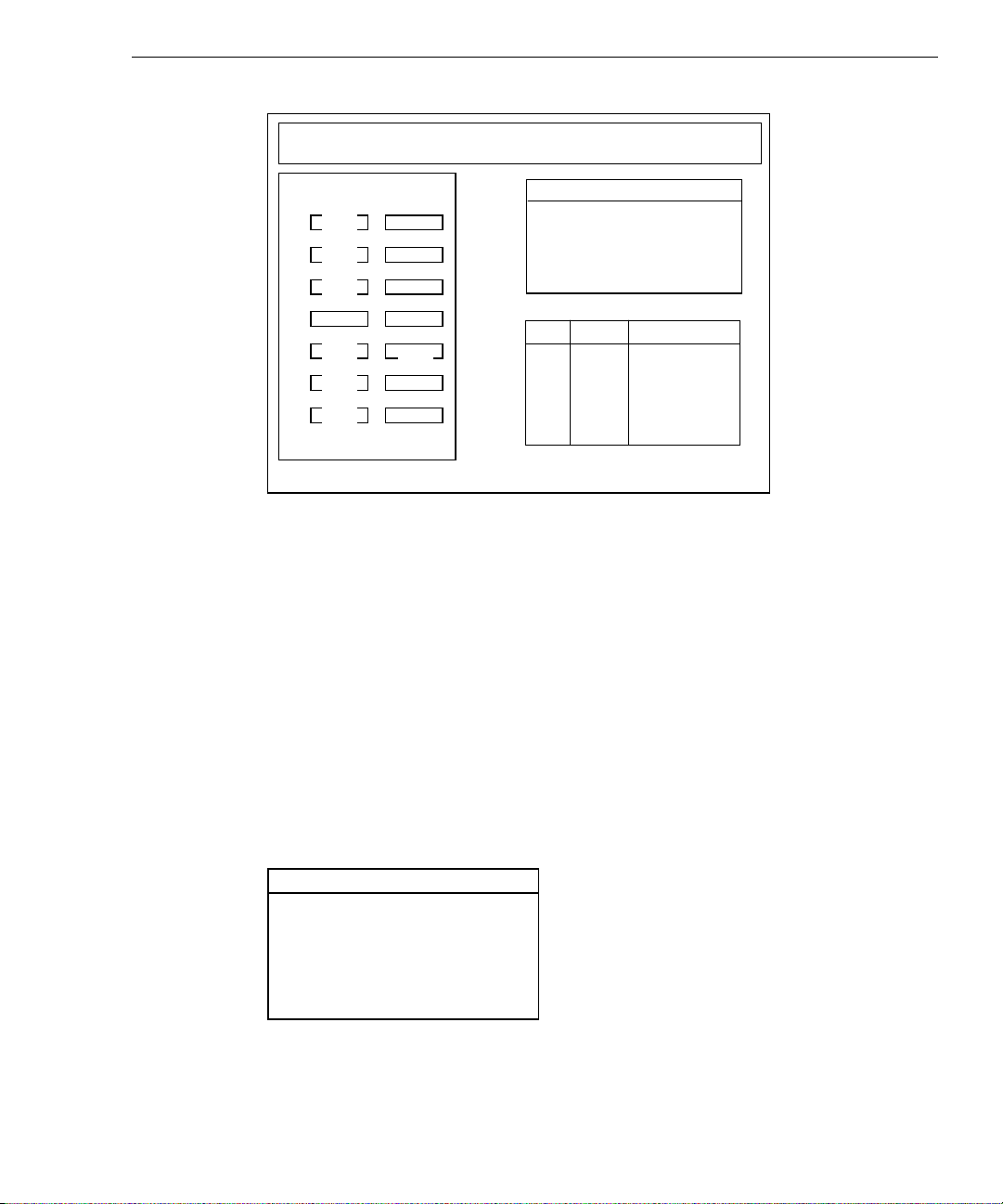
MYLEX Disk Array Controller-Configuration Utility Version X.XX X/XX/XX
2 Channel - 7 Target DAC960P #1 Firmware version x.xx
Tgt Chann el Nu mbe r
ID 0 1
A-0
0
ONL
A-1
1
ONL
A-2
2
ONL
3
A-3
4
ONL
B-0
5
ONL
B-1
6
ONL
CDR
Pack Definition
1. Create Pac k
2. Cancel Pac k
3. Arrange Pa ck
4. Device Inf ormation
PAK DRVS SIZE (MB)
A 4 4052
B 2 2026
4. After arranging all of the packs, press ESC to return to the New Configuration menu.
Then, select the Define System Drive option to proceed.
NOTE After arranging all of the packs, the Define System Drive option in the New Configuration
menu highlights. Refer to "Define System Drive" later in this section for more details.
51
Device Information in the Pack Definition menu displays information about a drive
connected to the RAID controller. The RAID controller can also display information for
other devices such as CD-ROM drives and tape drives.
To display device information:
1. From the Pack Definition menu, select Device Information. The first disk drive in the
disk drive list highlights.
2. Press
ENTER to display the information, or select another drive. The device information
displays as follows.
Device Information
Vendor : Conner
Model number : CFP1060ELK
Revision : 2035
Size : 1013 MB
Channel : 0
Target : 0
3. Press any key to return to the disk drive list, and select another drive. Press ESC to
return to Pack Definition menu.
Page 67
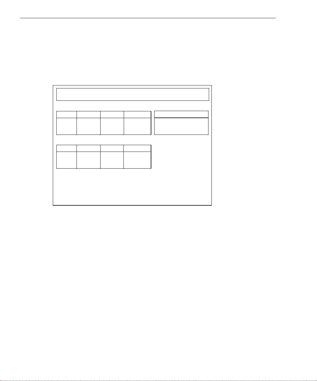
52
x
Define System Drive
Define System Drive of the New Configuration menu allows you to create one or more
system drives, and change the write policy for the selected system drive. You can define a
maximum of eight (8) system drives per DAC960 RAID controller. When you select Define
System Drive, a display similar to the following appears.
MYLEX Disk Array Controller-Configuration Utility Version X.XX X/XX/XX
2 Channel - 7 Target DAC960P
Pak/Drvs Size (MB) Pak/Drvs Size(MB)
A/4 4052
B/2 2026
Sys Drv Size (MB) RAID Write Mode
#1
Firmware version x.x
System Drive Definition
System Drive Definition
1. Create System Drive
2. Toggle Write Policy
The Pak/Drvs column (top left) lists all the current arranged packs and their sizes. The size
specified for each pack is the sum of the capacity of the drives in the pack.
NOTE If the drives in a pack are not the same size, then the size of the pack is a product of the
number of drives in the pack and the smallest drive in the pack.
The Sys Drv column (lower left) lists all the created system drives, their sizes, RAID levels,
and write policies. If you have not defined a system drive, the Sys Drv column is empty.
The column updates as you define the system drives.
NOTE Drives in an arranged pack that have not been configured into a system drive will be
automatically configured as standby (SBY) drives.
The System Drive Definition menu has two options: Create System Drive and Toggle Write
Policy. The following instructions allow you to create a system drive.
Page 68
DAC960 System Drive Size Limit
If your system has InterRAID disk arrays that use a DAC960P or DAC960PD RAID
controller board with version 2.x (or previous) firmware, be aware of the following
limitations:
u
You cannot create a system (logical) drive larger than 32,768 MB.
u
You can create a pack larger than 32,768 MB. However, if you do so, and then try to
create a system drive larger than 32,768 MB, the attempt to create the system drive will
fail.
WARNING If you try to create a system drive larger than 32,768 MB, the Mylex DACCF utility
program will insert your original drive size (default) and not create a system drive.
You can work around these limitations as follows:
1. Create one or more packs, with each pack containing up to eight disk drives of any size,
as required.
2. Divide each pack into system drives, with each system drive less than or equal to 32,768
MB.
3. Initialize the system drives.
53
If you require the entire amount of disk space to appear as a single system drive, rather than
as multiple 32 GB (or smaller) system drives, you can combine the smaller drives into a
logical volume using the Windows NT Disk Administrator. Combining the drives in this
way does not affect the speed or capacity of the disk subsystem.
NOTE The terms
To create a system drive:
1. You can define a maximum of eight (8) system drives per DAC960 RAID controller.
From the System Drive Definition menu, select Create System Drive. The first arranged
pack in the Pak/Drvs column highlights, and the RAID Levels display as follows.
RAID Level
RAID 0
RAID 1
RAID 5
RAID 6
RAID 7
system drive
and
logical drive
are used interchangeably.
Page 69
54
The following table briefly describes the supported RAID levels.
RAID
Level
Description
0 Data is striped across several physical drives, yielding higher performance
than is possible with individual drives. This level does not provide
redundancy.
1 Drives are paired and mirrored. All data is 100 percent duplicated on an
equivalent drive.
5 Data is striped across several physical drives. For data redundancy, drives
are encoded with rotated XOR redundancy. Parity is spread across all drives.
6 (0+1) Combines RAID Level 0 and RAID Level 1
7 Drives are seen independently as with any disk controller, or spanned and
seen as a single disk. This option does not provide redundancy.
NOTE Refer to Chapter 10 for detailed information about the various RAID levels.
Valid RAID levels are determined by the number of drives in the selected pack. You
can choose valid RAID levels only for the highlighted pack.
2. Select a RAID level for the highlighted pack, and then press
ENTER. The Enter Size
window shows the maximum possible size for the system drive being defined.
NOTE The size you specify is the actual size of the system drive, which includes the overhead for
the RAID level and redundancy. The size of the system drive is what the operating system
recognizes and uses. If you do not specify the size as the total available capacity, then you
can define another system drive on the same pack. The maximum size of a system drive is
32,768 MB.
3. Enter the size for the system drive. Two windows display as shown.
System Drive# = 0
RAID Level = 5
Capacity = 3039 MB
Do you want to create
this system drive?
NO
YES
NOTE Spanning a system drive across multiple packs is automatically done when the size of the
packs are the same.
Page 70

55
4. Select YES to create the system drive as defined. The system drive information displays
in the Sys Drv column.
Write-through caching reduces the risk of data loss in the event of a power failure.
Write-back caching improves performance, but the drawback is potential data loss if
power fails. If you want to change the policy to write-back for systems with a UPS
attached, refer to the instructions for changing the write policy in this section.
5. To create another system drive on a different pack, or on the unused space of the same
pack, repeat steps 1 through 4 above. If the space is insufficient on a partially defined
pack, a message explaining this condition displays when you try to define a system
drive.
6. After creating all the system drives, press
ESC twice. When the Save Configuration
window displays, select YES to save the configuration to flash EEPROM.
CAUTION If you select NO in the Save Configuration window, the currently defined configuration is
entirely discarded, and the program returns to the DACCF Main Menu.
NOTE If you press
and the program returns to the New Configuration menu. You can continue later with the
configuration process.
ESC in the Save Configuration window, the defined configuration remains intact
7. Initialize all of the new system drives. Refer to "05. Initialize System Drive" in this
chapter.
8. Ensure the Array Encl MGMT I/F option is set to Enabled to allow automatic disk drive
rebuild. Refer to “09. Advanced Functions,” in this chapter for more information about
the Array Encl MGMT I/F option and other hardware parameters.
The following instructions allow you to change the write policy for the system drives.
To change the write policy of a system drive:
1. From the System Drive Definition menu, select Toggle Write Policy. The write policy
of the first system drive highlights in the Write Mode column.
2. Press
ENTER to toggle the policy. For each system drive policy you need to change,
select the policy and press
ENTER.
3. Once you change the write policy on all the desired system drives, press
the System Drive Definition menu.
4. Press
ESC again to save the configuration.
ESC to return to
Page 71
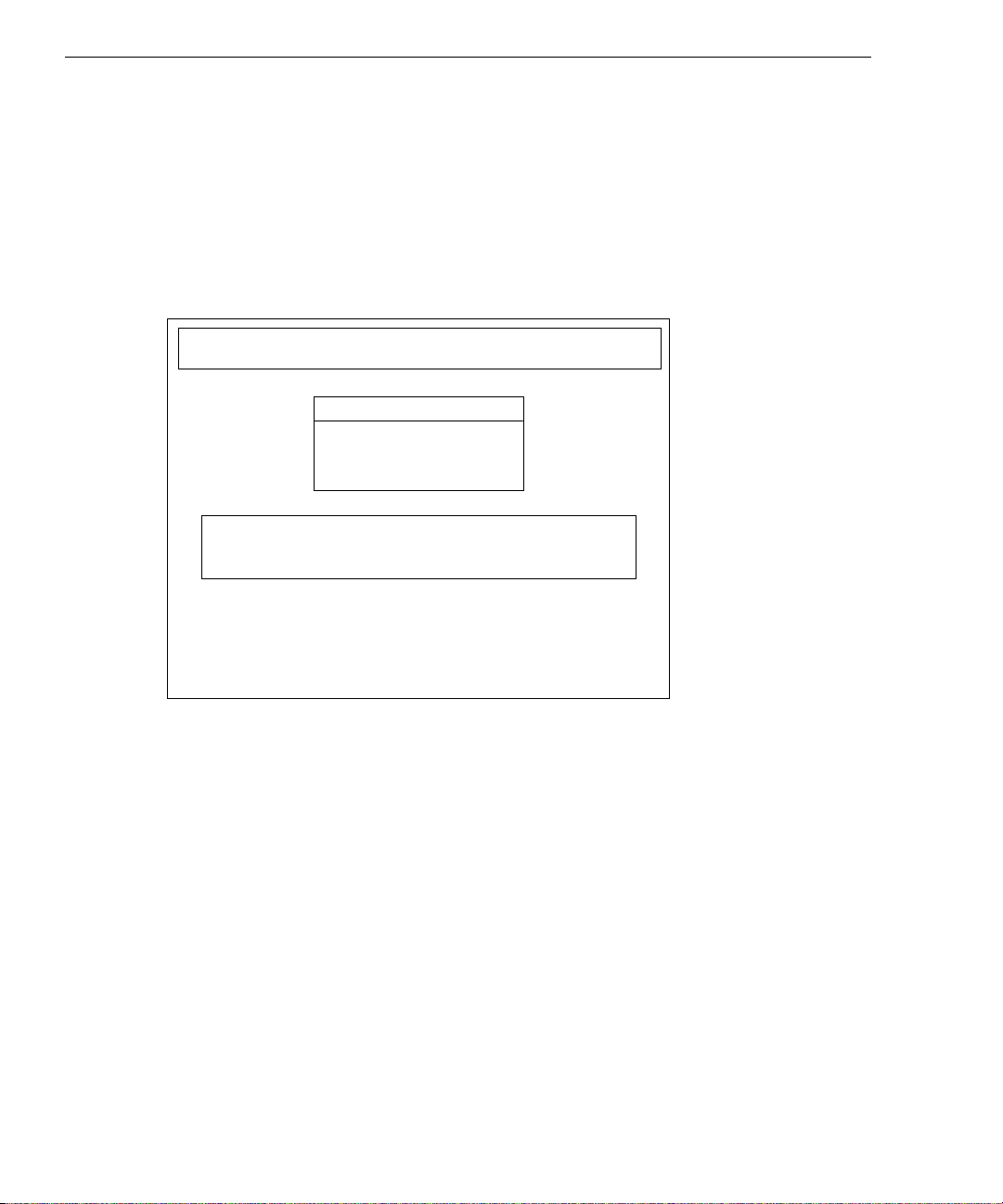
56
03. View/Update Configuration
Use the View/Update Configuration option in the DACCF Main Menu to view, edit, or
update an existing configuration, add more disk drives, or use existing standby drives as
normal drives. You can change the write policy of any system disk drive at any time by
selecting this option.
When you select View/Update Configuration, the following menu displays.
MYLEX Disk Array Controller-Configuration Utility Version X.XX X/XX/XX
2 Channel - 7 Target DAC960P #1 Firmware version x.xx
View/Update Co nfigurati on
1. Define Pack
2. Define Syst em Drive
Choose this option to view exis ting pack (s) OR cre ate,
arrange, ca ncel one o r mor e add itio nal p acks
Use Cursor keys for selection, hit <ENTER> to select, <ESC> to Exit
Define Pack
The existing packs can be canceled, deleted or changed. The newly added drives (RDY) and
the existing standby (SBY) drives can be created into packs. You can define a maximum of
eight (8) physical drives per pack. If you wish to cancel a pack, and more than one pack is
defined, be sure to cancel all packs in reverse order. For example, if you define three packs
(A, B, C), be sure to cancel pack C before canceling packs B and A, otherwise a “wrong
order” error message appears.
NOTE For creating and arranging packs, refer to “02. New Configuration” in this chapter.
When you select Define Pack, a display similar to the following appears.
Page 72
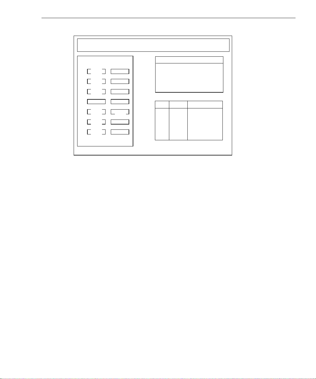
MYLEX Disk Array Controller-Configuration Utility Version X.XX X/XX/XX
2 Channel - 7 Target DAC960P #1 Firmware version x.xx
57
Tgt Chann el Nu mbe r
ID 0 1
A-0
0
ONL
A-1
1
ONL
A-2
2
ONL
3
A-3
4
ONL
B-0
5
ONL
B-1
6
ONL
CDR
Pack Definition
1. Create Pac k
2. Cancel Pac k
3. Arrange Pa ck
4. Device Inf ormation
PAK DRVS SIZE (MB)
A 3 3039
The disk drive list to the left of the display contains the details of existing configured drives.
ONL indicates the disk drive is online (usable) and CDR represents an installed CD-ROM
drive.
On the lower right side of the display, columns lists the configured packs (PAK), number of
drives in the packs (DRVS), and the size of the packs (SIZE) in megabytes.
Define System Drive
Define System Drive of the View/Update Configuration menu (after additional packs have
been created and arranged) allows you to create additional system drives. You can define a
maximum of eight (8) system drives per DAC960 RAID controller. You can also change the
write policy for the selected system drive. When you select Define System Drive, a display
similar to the following appears.
Page 73

58
MYLEX Disk Array Controller-Configuration Utility Version X.XX X/XX/XX
2 Channel - 7 Target DAC960P #1 Firmware version x.xx
Refer to “02. New Configuration” in this chapter for details of defining system drives.
04. Rebuild
Use the Rebuild option in the DACCF Main Menu to manually rebuild a replacement disk
drive for one that has failed. You can also rebuild a replacement disk drive automatically if
the Array Encl MGMT I/F option is set to Enabled. Refer to “09. Advanced Functions,” in
this chapter for more information about the Array Encl MGMT I/F option and other
hardware parameters.
Pak/Drvs Size (MB) Pak/Drvs Size(MB)
A/3 3039
Sys Drv Size (MB) RAID Write Mode
0 2026 1 WRITE THRU
Use Cu rsor keys for selection , hit <Ent er> to sel ect, <ESC > to Previous Menu
System Drive Definition
1. Create System Drive
2. Toggle Write Policy
Intergraph recommends that you use the automatic rebuild feature, rather than rebuild the
replacement disks manually. Systems using a redundant RAID level without standby drives
in place pose a risk should one of the online drives suddenly fail. The disk array will
continue to function without interruption, but the RAID system cannot tolerate further
physical drive failures, since data on the drives is no longer redundant. In order to make the
system redundant, you must replace and rebuild the failed disk drive.
NOTE The Rebuild option only works in systems with redundant system drives. If you attempt to
rebuild a drive in a non-redundant system, errors will occur.
To manually rebuild a new disk drive:
1. From the DACCF Main Menu, select Rebuild. A menu similar to the following
displays. The drive marked dead (DED) indicates a replacement disk drive.
Page 74

MYLEX Disk Array Controller-Configuration Utility Version X.XX X/XX/XX
2 Channel - 7 Target DAC960P #1 Firmware version x.xx
Tgt Chann el Nu mbe r
ID 0 1
A-0
0
ONL
A-1
1
ONL
A-2
2
ONL
3
4
5
6
A-3
DED
B-0
ONL
B-1
ONL
CDR
REBUILD
59
Select a drive using cursor keys, hit <Enter> to Rebuild, <ESC> to Quit
2. Select the drive marked DED, and press ENTER. Once the rebuild starts, a progress bar
displays.
When the rebuild completes, a message displays stating that the rebuild was a success, or
that errors occurred. If errors occur, open the Bad Block Table as described in “07. Tools”
in this chapter.
05. Initialize System Drive
Once a system drive is created (refer to “02. New Configuration” for details), it must be
initialized before the system can use it. The process fills the drives with initialized data and
synchronizes redundancy (mirror or parity). Errors can result if you fail to initialize a
system drive. For example, the drive may not function properly, fail to boot, fail to install
the operating system, or fail the consistency check. Also, a change in the size of the system
drives or packs requires that you initialize a system drive.
NOTE The initialization process is much faster with write-back cache enabled. You can enable
write-back cache for this process, and then disable it after initialization, if desired. Refer to
“03. View/Update Configuration” and select Define System Drive to change the write policy.
Once the system drive initialization starts, it cannot be aborted.
To initialize a system drive:
1. From the DACCF Main Menu, select Initialize System Drive. A list of system drives
displays with the first system drive highlighted. The following message also displays:
Page 75

60
Simultaneous initialization of two or more drives can be done.
Using cursor keys, move the required System drive box and hit
<Enter> to select. After selecting the required System drive(s),
move to the ‘START’ box and hit <Enter> to proceed with the
Initialization.
!!Warning: Initialization of the System drives will destroy data
on drives.
2. Press
ENTER to select the system drive. If multiple system drives exist, press ENTER on
each for simultaneous initialization. A check mark indicates the selected system drives.
3. After selecting all the system drives to be initialized, select the Start box and then press
ENTER. The following message displays:
Do you want to proceed with initialization?
4. Select YES to initialize all of the selected system drives. A progress bar indicates each
system drive initialized.
5. When the initialization of all system drives completes, press any key to save the
configuration and return to the DACCF Main Menu.
6. Ensure the Array Encl MGMT I/F option is set to Enabled. Refer to “09. Advanced
Functions,” in this chapter for more information about the Array Encl MGMT I/F option
and other hardware parameters.
06. Consistency Check
Use the Consistency Check option in the DACCF Main Menu to verify data consistency on
redundant system drives. You should always execute a Consistency Check after a system
crash or power interruption.
To perform a consistency check:
1. From the DACCF Main Menu, select Consistency Check. A list of current system
drives displays.
2. Use the cursor keys to select a system drive, and press
ENTER. If the system drive you
select is not a redundant drive, the following message displays:
Cannot Check consistency of a non-redundant System drive
If the selected drive is redundant, the consistency check starts. When the consistency
check completes, a message displays the results. If inconsistent blocks were found, the
following message displays.
Do you want to restore consistency?
3. Select YES to restore consistency to the system drive.
Page 76

NOTE Restoring consistency could mean loss of data in the blocks that were found inconsistent.
4. After restoring consistency, select another drive to check, or exit to the DACCF Main
Menu.
07. Tools
Use the Tools option in the DACCF Main Menu to perform many useful operations on the
RAID system. When you select the Tools option, a menu similar to the following displays.
MYLEX Disk Array Controller-Configuration Utility Version X.XX X/XX/XX
2 Channel - 7 Target DAC960P #1 Firmware version x.xx
Tgt Chann el Nu mbe r
ID 0 1
A-0
0
ONL
A-1
1
ONL
A-2
2
ONL
3
A-3
4
DED
B-0
5
ONL
B-1
6
ONL
CDR
1. Bad Bloc k Table
2. Error Co unts
3. Format D rive
4. Make Onl ine
5. Kill Dri ve
6. Backup/R estore Con f
7. Clear Co nfiguratio n
8. Print Co nfiguratio n
Tools
61
Press any key to continue
Bad Block Table
From the Tools menu, if you select Bad Block Table (BBT), the View Bad Block Table menu
displays and allows you to view the rebuild BBT and the write back BBT as follows.
View Bad Block
Table
View Rebuild BBT
View Write Back BBT
Select View Rebuild BBT to view information about the bad blocks detected on the system
drive during a rebuild. This information includes the location on the system drive where the
disk error occurred, its block number, and the number of consecutive blocks where disk
errors occurred. Press any key to return to the View Bad Block Table menu. The
information clears the rebuild BBT after you return to the View Bad Block Table menu.
Page 77

62
Select View Write Back BBT for information about the bad blocks detected during write
back operations. This information includes the location on the system drive where the disk
error occurred, its block number, and the number of consecutive blocks where the disk errors
occurred. Press any key to return to the View Bad Block Table menu. The information
clears the write back BBT after you return to the View Bad Block Table menu.
Error Counts
Use Error Counts in the Tools menu to view the error counts of the disk drives. The RAID
firmware maintains error counts for all physical drives.
To view the error counts:
1. From the Tools menu, select Error Counts. The first disk drive in the disk drive list
highlights.
2. Press the cursor keys to select a disk drive, and then press
ENTER. A display similar to
the following appears.
Channel # : 0
Target ID : 1
Parity Errors : 0
Soft Errors : 0
Hard Errors : 0
Misc. Errors : 0
3. Press ESC to return to the Tools menu. The error counts will clear the next time you
return to the View Bad Block Table menu.
Format Drive
Use Format Drive in the Tools menu to low-level format the physical drives. You can select
multiple drives for simultaneous formatting.
NOTE Only disk drives that are not configured into packs are available for low-level formatting.
To format drives:
1. From the Tools menu, select Format Drive. The first drive available for formatting
highlights.
2. Press
ENTER to select the drive, or move to another drive. The label for the selected disk
drives changes to format (FMT).
3. After selecting all the drives to format, press
All data will be LOST.
Proceed with Format?
ESC. The following message displays:
Page 78

4. Select YES. The following message displays:
Do you really want to Format selected drives?
5. Select YES to start formatting. The following message displays:
Formatting all the selected drives. Please wait...
Once complete, the disk drives return to their original states, except for the drives labeled
UNF (unformatted), which will be changed to RDY (ready).
Make Online
Use the Make Online option in the Tools menu to change a disk drive from the unusable
(DED) state to the online (ONL) state. Disk drives that are labeled DED and not configured
into a pack cannot be made online.
To make drives online:
1. From the Tools menu, select Make Online. A warning message displays stating the
consequences of making a drive online.
2. Press a key to dismiss the warning message. The first drive available to the Make
Online function highlights.
63
3. Press the cursor keys to highlight a drive, and then press
ENTER. A confirmation
message displays:
Do you really want to make drive Online?
4. Select YES. The drive state changes to ONL.
5. After selecting all the drives to be made online, press
NOTE You can quickly make all DED drives online by restoring the RAID configuration file, as
described later in “Backup/Restore Conf.”
ESC.
Kill Drive
Use the Kill Drive option in the Tools menu to change an ONL disk drive to DED. Only
physical drives included in a configured pack can be killed.
To kill a drive:
1. From the Tools menu, select Kill Drive. A warning message displays stating the
consequences of killing a drive.
2. Press a key to dismiss the warning message. The first drive available for killing
highlights.
Page 79

64
3. Press the cursor keys to highlight a drive, and then press ENTER. A confirmation
message displays:
Do you really want to KILL the drive?
4. Select YES. The drive state changes to DED.
5. After selecting all the drives to be killed, press
ESC.
Backup/Restore Conf
Use the Backup/Restore Conf option in the Tools menu to save a new configuration to a
diskette (back up), or to restore a configuration file that has become corrupted or lost. For
every InterRAID cabinet connected to the system, always back up a configuration file.
To back up a configuration to floppy:
1. Insert a diskette into the floppy disk drive.
2. From the Tools menu, select Backup/Restore Conf.
3. Select Backup.
4. Press
ENTER to confirm the warning message.
5. Type a filename for the configuration file. Do not include directory paths. Use a .CFG
extension as part of the filename to identify it as a configuration file. The following
message displays:
Existing File, if any will be overwritten!
6. Select YES and press
ENTER.
7. Remove the diskette from the floppy disk drive.
To restore a configuration:
1. From the Tools menu, select Backup/Restore Conf.
2. Select Restore.
3. Press
ENTER to confirm the warning message.
4. Key in the filename for the configuration file. Do not include directory paths. If you
used a .CFG extension as part of the filename, include the extension.
WARNING Do not key in the filename used for the ASCII version of the RAID configuration file.
The ASCII version will overwrite the binary code for setting the registers, causing
damage to the RAID controller board. The board must be replaced.
The following message displays:
Do you really want to Restore Configuration?
Page 80

CAUTION The restored configuration file must match the hardware configuration. DACCF assumes the
number of physical drives installed in the InterRAID cabinet is the same as the number of
drives configured in the configuration file.
5. Select YES and then press ENTER. The following message displays:
Are you sure you want to Restore Configuration?
65
6. Select YES and then press
ENTER. The configuration is read from the file and saved on
the RAID controller board.
7. Exit DACCF and restart the system for the restored configuration to take effect.
Clear Configuration
Use the Clear Configuration option in the Tools menu to erase the existing configuration of
the RAID controller board.
To clear the existing configuration:
1. From the Tools menu, select Clear Configuration. The following message displays:
The existing config will be destroyed!
2. Select YES to clear the configuration.
The disk drives in the disk array will not be accessible until you define a new configuration.
Print Configuration
Use the Print Configuration option in the Tools menu to save a copy of the configuration in
ASCII format to a floppy diskette or hard disk drive.
To save an ASCII version of the configuration file:
1. Insert a diskette into the floppy disk drive.
2. From the Tools menu, select Print Configuration.
3. Type the filename for the ASCII version of the configuration file. Do not include
directory paths. Include the .TXT extension as part of the filename.
NOTE Do not key in the filename of the binary version of the configuration file.
4. Select YES to confirm the filename.
5. To view the file, exit DACCF. At the command prompt, type the following and press
ENTER, where filename is the name of the ASCII file you just made:
edit filename
Page 81

66
6. To print a hardcopy, use the editor’s print command.
7. Remove the diskette from the floppy disk drive.
08. Select DAC960
When you have multiple RAID controller boards in the system, the Select DAC960 option in
the DACCF Main Menu allows you to select the RAID controller that needs to be
configured. You can configure only one RAID controller board at a time.
To select a RAID controller board:
1. From the DACCF Main Menu, select Select DAC960. A list of all installed RAID
controller boards displays. Refer to “Starting DACCF” earlier in this chapter for
information about determining the difference between primary and secondary RAID
controller boards.
2. Select the RAID controller board to configure, and then press
ENTER. Note that the
banner at the top of the display shows the RAID controller board currently selected.
3. DACCF scans the disk array to detect the drives connected to the controller and returns
to the DACCF Main Menu.
NOTE If there are errors associated with the selected controller, refer to “Error Conditions” later in
this chapter.
09. Advan ced Functions
When you select the Advanced Functions option from the DACCF Main Menu, the
following menu displays.
Page 82

MYLEX Disk Array Controller-Configuration Utility Version X.XX X/XX/XX
2 Channel - 7 Target DAC960P #1 Firmware version x.xx
Edit/View P arameters
Hardware Param eters
Physical Param eters
SCSI Xfer Para meters
Startup Parame ters
Choose this option to view or e dit the c ontrollers
Hardware fe atures lik e bat tery back up.
Use Cursor keys for selection, hit <ENTER> to select, <ESC> to Exit
Hardware Parameters
When you select Hardware Parameters, a menu similar to the following displays. Use the
arrow keys to select a parameter, and press
ENTER to toggle the settings.
67
Hardware Par ameters
Battery Backup Disabaled
Array Enclosure Man agement Enabled
StorageWorks Fault MGMT. (TM) Disabled
NOTE The default hardware parameters are: Battery Backup = Disabled, Array Enclosure
Management. I/F (AEMI) = Enabled, StorageWorks Fault MGMTI/F = Disabled.
The InterRAID-6, InterRAID-8, and InterRAID-12 disk arrays do not support the Battery
Backup option. Intergraph recommends connection to a UPS to guard against data loss.
The Array Enclosure Management I/F option should be set to Enabled each time you create a
new configuration. This option allows the Windows NT Server operating system to
recognize a failed drive and to begin the automatic on-line rebuild of the drive. Intergraph
recommends the automatic rebuild capability for every InterRAID configuration.
The StorageWorks Fault Management option is not used by the InterRAID-6, InterRAID-8,
and InterRAID-12 disk arrays. The default is Disabled.
Page 83

68
Physical Parameters
When you select Physical Parameters, a menu similar to the following displays. The three
physical parameters that can be set are Default rebuild rate, the Stripe size (K bytes), and
Controller read ahead. Use the arrow keys to select a parameter, and press
ENTER to toggle
the settings.
Physical Par ameters
Default Rebuild Rate 50
Stripe Size (K bytes) 8
Controller read ahead Enabled
NOTE The default physical parameters are: Default rebuild rate = 50, Stripe size (K bytes) = 8,
Controller read ahead = Enabled.
Use the Default rebuild rate option to change the rebuild rate from 0 to 50. A rebuild rate of
50 is the maximum. A higher value assigns a higher priority to the rebuild activity rather
than the other activities, resulting in a faster drive rebuild, but slower disk performance. If
the rebuild needs the least priority, set the rebuild rate to 0 to increase performance for other
activities.
The Stripe size (K bytes) option changes the way of accessing the information on the drives.
Stripe sizes of 8K, 16K, 32K and 64K are supported. A higher stripe size results in a higher
sequential throughput and a slightly reduced random throughput.
WARNING When you select a different stripe size, all existing data on the drives will be lost.
Back up the drives before changing the stripe size.
The Controller read ahead option, when set to Enabled, directs the controller to read the data
from the block requested and from one block ahead. This method of reading data assumes
that the subsequent block of data will soon be requested. The Controller read ahead option is
Enabled by default and will increase the performance of read operations.
SCSI Xfr Parameters
The SCSI Xfr Parameters menu allows you to change Data transfer rate and Command
tagging parameters for each channel on the current RAID controller board. When you select
the SCSI Xfr Parameters from the Edit/View Parameters menu, you are prompted to select a
channel. After selecting the channel, the following menu displays.
Page 84

SCSI Xfr Paramet ers
Data transfer rate 10 MHz
Command tagging Enabled
SCSI data bus width 16 Bit
NOTE The default SCSI Xfr parameters are: Data transfer rate = 10 MHz, Command tagging =
Enabled, SCSI data bus width = 16 Bit.
The Data transfer rate option sets the default SCSI negotiation rate for the selected SCSI
channel. The options are 10 MHz, 8 MHz, 5 MHz, and Asynchronous. The default is 10
MHz for the disk drives.
The Command tagging option enables or disables command tagging support for the selected
SCSI channel. The default is set to Enabled.
The SCSI data bus width option allows you to select either 8 Bit or 16 Bit parameters.
Verify that 16 Bit is enabled.
Startup Parameters
69
The options for the Startup Parameters (Spin up option, Number of devices per spin, and
Delay) can be used to set up the way the disk drives spin initially. However, by default, the
InterRAID cabinet power supplies manage how the drives spin up, so these options do not
need changing. The disk drives spin up one at a time, with a four-second delay between spin
up. If you change the Spin up parameter to Automatic, then the Devices per spin and Delay
parameters can also be changed. The following menu shows the startup parameters.
NOTE This parameter only applies to the disk drives in the disk array, not to other SCSI devices.
Startup Para meters
Spin up option On power
Number of devices per spin 0
Delay (seconds) 0
NOTE The default startup parameters are: Spin up option = On power, Number of devices per spin
= 0, Delay (seconds) = 0.
Page 85

70
10. Diagnostics
The last option in the DACCF Main Menu is for performing system level diagnostics on the
selected RAID controller. Diagnostics are reserved for Intergraph field engineer use only.
An engineer can access the diagnostics with an uppercase Y as supported under DACCF
version 3.10.
NOTE Before running the diagnostics, refer to the README file on the DACCF diskette for
limitations and warnings about the diagnostics.
Error Conditions
During startup, DACCF may report the following types of messages:
u
Installation aborted errors
u
NVRAM/Flash configuration mismatch errors
u
Controller checksum errors
The following sections describe the errors.
Installation Aborted Errors
If reporting an installation abort condition, the following message displays:
Installation aborted
The cause of this error includes a faulty SCSI cabling, SCSI channel, controller, or improper
power to the disk drives. This error also occurs if you power off the InterRAID cabinet
before the system.
To recover from an aborted installation:
1. Press any key. A list of all the disk drives displays. The state of all the drives whose
state changed since the last time the InterRAID cabinet was powered off also displays.
2. Press the
system drive and other associated information already stored.
3. Power off the system and power off the InterRAID cabinet. Then, restart the InterRAID
cabinet and the system.
S key to save the displayed configuration. This process does not affect the
Page 86

NVRAM/Flash Configuration Mismatch Errors
If detecting a mismatch between the configurations saved in the NVRAM and flash
EEPROM, the following message displays:
The NVRAM and FLASH configurations do not match. Proceeding further
will allow selection between NVRAM and FLASH configurations.
The cause of this error is probably due to a corrupted NVRAM.
To recover from the mismatch:
1. Press a key to display the Load Configuration Menu.
Load Config uration
Load FLASH Configuration
Load NVRAM Configuration
2. Normally the flash EEPROM contains the most accurate configuration. Choose the
Load Flash configuration option.
71
3. Press the
S key to save the configuration.
4. Power off the system and power off the InterRAID cabinet. Then, restart the InterRAID
cabinet and the system.
Controller Checksum Errors
If a configuration checksum error is present, DACCF displays the following message,
advising the user to reset the RAID to a default configuration.
The controller configuration table has a checksum error. This may
be due to corruption in the configuration tables stored in the
controller’s FLASH memory. To overcome this problem the
configuration table has to be restored to the default values. Then
rerun the utility and restore the required configuration from a
previously backed up file using menu options under “Tools.” If
there is no backup then the controller parameters have to be set to
the required values using “Advanced Functions” option from the “Main
Menu.” Setting wrong values may cause data loss!
To recover from the controller checksum error:
1. Press the
2. Exit DACCF, power off the system and power off the InterRAID cabinet.
S key to save the current configuration.
Page 87

72
3. Wait at least 30 seconds; then, restart the InterRAID cabinet and restart the system with
the DACCF diskette in the floppy disk drive.
4. At the command prompt, key in daccf.
5. When the DACCF Main Menu displays, select the Tools option.
6. Select the Backup/Restore Conf option, then select Restore Configuration.
7. Key in the filename for the configuration file. Do not include directory paths. If you
used a .CFG extension as part of the filename, include the extension.
WARNING Do not key in the filename used for the ASCII version of the RAID configuration file.
The ASCII version will overwrite the binary code for setting the registers, causing
damage to the RAID controller board. The board must be replaced.
8. After restoring the configuration, exit DACCF and restart the system.
Common DACCF Procedures
This section provides a set of common procedures used to configure the disk arrays.
Enabling Automatic Rebuild
The Array Encl MGMT I/F option allows you to hot swap disk drives and automatically
rebuild the replacement disk drive. If Array Encl MGMT I/F is enabled, the RAID
controller detects the replacement drive and automatically begins the rebuild process.
Array Encl MGMT I/F is enabled by default, and must be enabled each time you change the
RAID configuration. RAID configurations for additional disk arrays do not have Array Encl
MGMT I/F enabled by default.
To enable automatic rebuild:
1. Ensure the boot sequence for the system is A:, C:.
2. Insert the DACCF diskette into the floppy disk drive.
3. Restart the system.
4. At the command prompt, key in daccf.
5. If you have multiple RAID controller boards installed in the system, select the controller
to be configured.
6. When the DACCF Main Menu displays, select the Advanced Functions option.
7. Select the Hardware Parameters option.
Page 88

8. Toggle the Array Encl MGMT I/F option to Enable.
73
9. Press
ESC twice to save the automatic rebuild setting.
10. Select Yes to save the configuration.
11. Exit DACCF, remove the diskette, and then restart the system.
Changing the Write Policy
Follow these steps to change the write policy of system drives.
To change the write policy:
1. Ensure the boot sequence for the system is A:, C:.
2. Insert the DACCF diskette into the floppy disk drive.
3. Restart the system.
4. At the command prompt, key in daccf.
5. If you have multiple RAID controller boards installed in the system, select the controller
to be configured.
6. When the DACCF Main Menu displays, select the View/Update Configuration option.
7. Select the Define System Drive option; then, select the Toggle Write Policy option.
8. Use the cursor keys to select a system drive; then, toggle the write policy option to Write
Through or Write Back, as desired.
9. Press
ESC twice to save the write policy setting.
10. Select Yes to save the configuration.
11. Exit DACCF, remove the diskette, and then restart the system.
Configuring Additional Disk Arrays
Additional disk arrays are not configured at the factory. You can use the quick configuration
process outlined below to configure an additional disk array for RAID Level 5.
To configure for RAID Level 5:
1. If DACCF is already running, go to the DACCF Main Menu. Skip to step 6.
2. Ensure the boot sequence for the system is A:, C:.
3. Insert the DACCF diskette into the floppy disk drive.
4. Restart the system.
Page 89

74
5. At the command prompt, key in daccf.
6. If you have multiple RAID controller boards installed in the system, select the controller
to be configured.
7. From the DACCF Main Menu, select the Automatic Configuration option (which
defaults to RAID Level 5).
8. If a WARNING window displays, you have selected a controller that has been previously
configured. Select YES to overwrite the configuration, or select NO to discontinue.
You can use Select DAC960 of the DACCF Main Menu to select another controller, and
then re-select Automatic Configuration if desired.
9. Select YES to enable write-back cache, if desired. The configuration displays. Press
any key to continue.
10. Select the Initialize System Drive option of the DACCF Main Menu to initialize the
system drive.
11. When the system drive list displays, select Sys Drv 0 and press
12. At the confirmation window, use the arrow key to select YES and press
13. A status bar shows the progress of the initialization. After initialization is complete,
press any key to continue.
14. From the DACCF Main Menu, select Advanced Functions, and then select Hardware
Parameters.
15. Toggle the Array Encl MGMT I/F option to Enabled.
16. Press
ESC twice to save the setting.
17. Select Yes to save the configuration.
18. Exit DACCF, remove the diskette, and then restart the system.
19. Under Windows NT, run Disk Administrator. Select YES to create a signature file.
20. Partition and format the disk space. Use the Help command for specific instructions to
partition and format the drive.
Recovering Unusable (DED) Disk Drives
If the InterRAID cabinet is powered down before the system, or if a power outage occurs, all
of the system drives may show up as unusable (DED) the next time you power on the system.
Should this occur, use the following procedures to make the drives online (ONL).
ENTER.
ENTER.
CAUTION Perform the following procedures only if all disk drives are marked DED by an incorrect
power down sequence, or if a power outage occurs. If a particular drive is truly unusable,
replace it as described in Appendix B, “Troubleshooting.”
Page 90

To recover a DED disk drive:
1. Ensure the boot sequence for the system is A:, C:.
2. Insert the DACCF diskette into the floppy disk drive.
3. Restart the system.
4. At the command prompt, key in daccf.
5. If you have multiple RAID controller boards installed in the system, select the controller
to be configured.
6. When the DACCF Main Menu displays, select Tools.
NOTE You can restore each drive one at a time by selecting Make Online of the Tools menu. If you
prefer to change all of the drives at once, proceed to step 10 and use the Backup/Restore
Conf option.
7. To restore each drive individually, select Make Online and press ENTER.
8. The cursor will display in the drive matrix area. Use the arrow keys to select the dead
drive and press
ENTER.
9. Select YES in the confirmation window.
75
10. Repeat steps 6 through 8 for each drive marked DED. Then, proceed to step 13.
11. To backup or restore all drives at once, select the Backup/Restore Conf option of the
Tools menu. Press
ENTER to confirm the warning message.
12. Key in the filename for the configuration file. Do not include directory paths. If you
used a .CFG extension as part of the filename, include the extension.
WARNING Do not key in the filename used for the ASCII version of the RAID configuration file.
The ASCII version will overwrite the binary code for setting the registers, causing
damage to the RAID controller board. The board must be replaced.
The following message displays:
Do you really want to Restore Configuration?
CAUTION The restored configuration file must match the hardware configuration. DACCF assumes the
number of physical drives installed in the InterRAID cabinet is the same as the number of
drives configured in the configuration file.
13. Select YES and then press ENTER. The configuration is read from the file and saved on
the RAID controller board.
Page 91

76
14. Press ESC to exit the Tools menu.
15. Press
ESC to exit DACCF, and then select YES at the confirmation window.
16. Remove the DACCF diskette and restart the system.
Page 92

6 Using MegaRAID BIOS
This chapter pertains only to systems containing the MegaRAID controller. If your system
contains either the DAC960P or DAC960PD controller, refer to Chapter 5.
NOTE Chapter 1 describes how to determine which controller was shipped with your system.
This chapter describes how to upgrade the MegaRAID driver and use the MegaRAID BIOS
Configuration Utility to configure disk arrays and logical drives. Since the utility resides in
the MegaRAID BIOS, its operation is independent of the operating system on your system
base unit. Intergraph includes MegaRAID BIOS on a diskette delivered with the InterRAID
cabinets.
The topics in this chapter also include the following:
u
Startup Sequence
u
Management Menu Options
u
Exiting Setup
77
u
Setup menu tree
u
Configuring arrays and logical drives
u
Rebuilding failed disk drives
u
Using a pre-loaded SCSI drive “as-is”
NOTE If you need to load the new driver, follow the applicable instructions in the following section
for Windows NT 3.51 or Windows NT 4.00. The MegaRAID driver resides on the same
diskette containing the MegaRAID Power Console Utility.
Updating the MegaRAID Driver
The MegaRAID driver provides an interface for administering the InterRAID disk array
products. After configuring the Windows NT operating system, you must install the updated
Intergraph MegaRAID driver. An icon will be automatically created in the Power Console
program group.
To install the updated MegaRAID driver for use with Windows NT 3.51:
1. Boot the system and log in as administrator.
2. At Program Manager, open Windows NT Setup.
Page 93

78
3. From the Options menu, select Add/Remove SCSI Adapters.
4. Select the MegaRAID driver; then, select Remove.
5. Select OK at the Warning dialog; then, select OK again.
6. At the Warning dialog, select Add; then, select OK. Windows NT Setup displays a list
of adapters.
7. Scroll to OTHER (Requires disk from a hardware manufacturer).
8. Insert the diskette containing MegaRAID NT driver into the floppy disk drive, and
select OK. The Select OEM Option dialog displays with the MegaRAID adapter
highlighted.
9. Select OK. Setup displays the Select SCSI Adapter Option dialog.
10. Select Install. Setup displays a message that the driver is already present on the system.
11. Select New; then, select Continue at the prompt to specify the path to the adapter files.
12. At the SCSI Adapter Menu, select Close.
13. From the Options menu, select Exit.
14. Reboot the system.
To install the updated MegaRAID driver for use with Windows NT 4.00:
1. Boot the system and log in as administrator.
2. Open Control Panel.
3. Select SCSI Adapters icon.
4. Click the Drivers tab.
5. Select the MegaRAID driver.
6. Click Remove to remove the old driver.
7. Click the Drivers tab again.
8. Click Add.
9. Click Have Disk.
10. Follow the instruction on the screen to install the updated driver. This will create a
MegaRAID Program Group and a MegaRAID Power Console Program item.
11. Remove the diskette containing the MegaRAID driver from the disk drive.
12. Reboot the system.
Page 94

Startup Sequence
When the system boots, press CTRL+M when the following appears:
MEGARAID CONTROLLER BIOS Version x.xx Aug 1, 1996
Host Adapter-1 Firmware Version x.xx DRAM Size 8 MB
0 Logical Drives found on the Host Adapter
0 Logical Drives handled by BIOS
Press <Ctrl><M> to run MegaRAID BIOS Configuration Utility
NOTE If you do not press CTRL+M within a few seconds of the prompt, the system continues the
normal boot procedure.
For each MegaRAID controller in the system, the firmware version, DRAM size, and the
status of logical drives on that controller displays. When you press
Management Menu displays:
-------------- Management Menu ---------------Configure
Initialize
Objects
Format
Rebuild
Check Consistency
Select Adapter
Disable BIOS
CTRL+M, the following
79
Management Menu Options
The Management main menu options are as follows:
Option
Configure Configures physical arrays and logical drives
Initialize Initializes one or more logical drives
Objects Individually accesses controllers, logical drives, and physical drives
Format Low-level formats a hard disk drive
Rebuild Rebuilds a failed disk drive
Check
Consistency
Select Adapter Selects a MegaRAID host adapter (controller)
Disable BIOS Disables the BIOS
Description
Verifies that the redundancy data is correct in logical drives using
RAID level 1, 3, or 5
Page 95

80
Exiting MegaRAID BIOS Configuration Utility
To exit the MegaRAID BIOS configuration utility, press ESC while the Management menu is
displayed. Choose Yes at the prompt. You must then reboot the system. The MegaRAID
BIOS message displays again. Press
ESC when the BIOS Configuration Utility prompt
displays.
Management Menu Tree
The following is an expansion of the Management menu options. The menu items are
explained on the following pages.
CONFIGURE -- Easy Configuration
New Con fig uration
View/Add Configuration
Clear Configuration
INITIALIZE -OBJECTS -- Adapter -- Clear Config uration
FlexRA ID Pow e rFail
Flexible (Dyn amic) Sizing
Disk Spin -up Tim ings
Chip Set Type
Cache Fl ush Timi ng s
Rebuild Rate
Alarm Control
Ultra SCSI
Auto Rebuild
Logical Drive -- Initialize
Check Consistency
View/Update Parameters
Physical Drive -- Rebuild
Format
Make Online
Fail Drive
Make Hotspare
View Drive Information
Synchronous Negotiation
SCSI-2 Command Tagging
SCSI Channel -- Terminate Hi gh 8 Bits
FORMAT -REBUIL D -CHECK CONSISTENCY - SELECT ADAPTER - -
Termin ate W ide Channel
Disable Termi natio n
Set Pow erOn Defaults
Page 96

Configure Menu
Choose the Configure option from the ManagementSetup main menu to select a method for
configuring arrays and logical drives.
81
Option
Easy
Configuration
New
Configuration
View/Add
Configuration
Clear
Configuration
Description
Select this option to perform a basic logical drive configuration where
every physical array you define is automatically associated with exactly
one logical drive.
Select this option to discard the existing configuration information and to
configure new arrays and logical drives. In addition to providing the
basic logical drive configuration functions, New Configuration allows you
to associate logical drives with multiple or partial arrays.
Select this option to examine the existing configuration and/or to specify
additional arrays and logical drives. View/Add Configuration provides the
same functions available in New Configuration.
Select this option to erase the current configuration information from the
MegaRAID controller non-volatile memory.
Initialize Menu
Choose Initialize from the Management menu to initialize one or more logical drives.
Initializing typically follows configuring a new logical drive.
WARNING Initializing a logical drive destroys all data on the logical drive.
Objects Menu
Choose Objects from the Management menu to access the controllers (adapters), logical
drives, physical drives, and SCSI channels individually. You can also change certain
settings for each object. The Objects menu options are described below.
Objects
Adapter
Logical Drive
Physical Drive
SCSI Channel
Ensure the following important default settings of the Objects menu:
Page 97

82
u
Under Objects/Adapter/Chip Set Type, ensure Others is selected.
u
Under Objects/Adapter/Alarm Control, ensure Disable is selected.
u
Under Objects/Adapter/Spinup Timings/Spinup Parameters, set to two drives every six
seconds.
u
Under Objects/Adapter/Ultra SCSI, set to Disabled.
Adapter
If your system has more than one MegaRAID controller, choose the Adapter option from the
Objects menu to select a MegaRAID controller and to modify the parameters.
The following displays:
-------------- Adapter x ---------------Clear Configuration
FlexRAID PowerFail = DISABLED
Flexible Dynamic Sizing
Disk Spin-up Timings
Chip Set Type
Cache Flush Timings
Rebuild Rate
Alarm Control
Ultra SCSI = DISABLED
Auto Rebuild = ENABLED
The following table describes the Adapter menu options.
Option
Clear
Configuration
FlexRAID
Description
Choose this option to erase the current configuration from the controller
non-volatile memory.
Choose this option if you have battery backup installed.
PowerFail
Flexible
Dynamic
Choose this option if you plan on adding disk drives to the array and want
to use the extra space without rebooting. Default is disabled.
Sizing
Disk Spin-up
Timings
Choose this option to set the method and timing for spinning up the hard
disk drives in the system. Default is 2 every 6 seconds.
Chip Set Type Choose this option to program the MegaRAID controller for a specific
motherboard chip set type, such as Intel Neptune, Intel Saturn, or other
chip set. Default is other.
Cache Flush
Timings
Choose this option to set the cache flush interval to once every 2, 4, 6, 8,
or 10 seconds. Default is 2.
Page 98
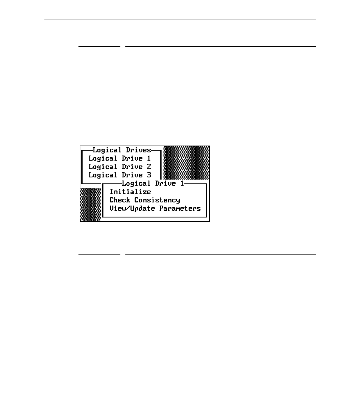
Option Description
Rebuild Rate Choose this option to change the rebuild rate for the controller. You can
also display the firmware version number.
Alarm Control Choose this option to enable, disable, or silence the onboard alarm tone
generator. Default is disable.
Ultra SCSI Choose this option to enable or disable Ultra SCSI. Default is disabled.
Auto Rebuild Choose this option to enable automatic rebuild. Default is enabled.
Logical
Drive
Choose the Logical Drive option from the Objects menu to select a logical drive and to
perform the listed actions.
83
The following table describes the Logical Drives options.
Option
Description
Initialize Choose this option to initialize the selected logical drive. This should be
done for every logical drive you configure.
Check
Consistency
Choose this option to verify the correctness of the redundancy data in the
selected logical drive. This option is only available if RAID level 1, 3, or
5 is used.
View/Update
Parameters
Choose this option to display the properties of the selected logical drive;
you can modify the cache write policy, the read policy, and the I/O policy
from this menu.
Page 99
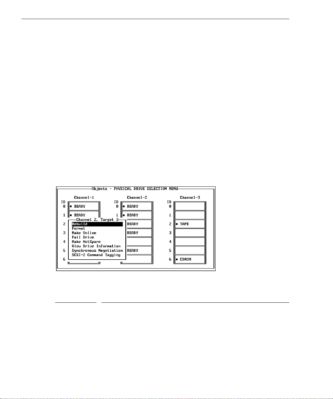
84
The following table defines some terms you will see while configuring drives and running
the MegaRAID BIOS configuration utility.
READY Disk drive ready for configuration
ONLINE Disk drive ready for use
REBUILD Disk drive to be replaced
OFFLINE Unformatted drive
PACK Configured pack
DRIVES Number of drives in a pack
SIZE Size of the packs (in megabytes)
HOTSP Disk drive configured as hot spare (standby) drive
Physical
Drive
Choose the Physical Drive option from the Objects menu to select a physical device and to
perform the operations listed in the table below. The physical hard disk drives in the system
are listed. Move the cursor to the desired device and press
ENTER to display the following:
The following table describes the Physical Drive options.
Option
Description
Rebuild Choose this option to rebuild the selected disk drive.
Format Choose this option to low-level format the selected disk drive.
Make Online Choose this option to change the state of the selected disk drive to Online.
Fail Drive Choose this option to change the state of the selected disk drive to Fail.
Make HotSpare Choose this option to designate the selected disk drive as a hot spare.
View Drive
Information
Choose this option to display the manufacturer data for the selected
physical device.
Page 100
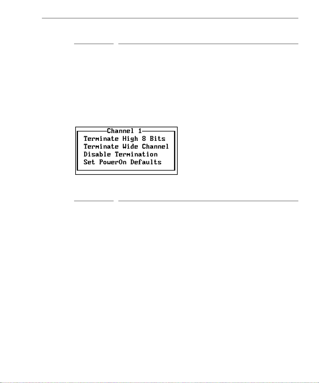
Option Description
Synchronous
Negotiation
SCSI-2
Command
Tagging
SCSI Channel
Choose the SCSI Channel option from the Objects menu to select a SCSI channel on the
currently selected controller.
The following table describes the SCSI Channel options.
Choose this option to enable or disable synchronous negotiation for the
selected physical device. The default is Enabled.
Choose this option to set the number of queue tags per command to 2, 3,
or 4, or to disable command tagging. The default setting is 4 queue tags.
85
Option
Terminate
High 8 Bits
Terminate
Wide Channel
Disable
Termination
Set PowerOn
Defaults
Description
Choose this option to enable termination on the selected channel for the
upper eight bits and disable termination on the controller for the lower
eight bits. This setting is required if the selected SCSI channel is
terminated with 8-bit devices at both ends.
Choose this option to enable wide channel termination for the selected
channel. This is required if the MegaRAID controller is at one end of the
SCSI bus for the selected channel.
Choose this option to disable termination on the MegaRAID controller for
the selected channel. This option should be used if the selected SCSI
channel is terminated with Wide devices at both ends.
Choose this option to have the MegaRAID controller examine its SCSI
channels and to set its termination automatically.
Format Menu
Choose Format from the Management menu to low-level format one or more physical drives.
WARNING Formatting a hard drive destroys all data on the drive.
 Loading...