

Page 1

Wildcat 4210 Graphics
Hardware User’s Guide
July 2000
D1AV00080
Page 2

Copyright
2000 Intergraph Corporation. All rights reserved. This document contains information protected by copyright, trade
secret, and trademark law. This document may not, in whole or in part, be reproduced in any form or by any means, or
be used to make any derivative work, without written consent from Intergraph Corporation.
Use, duplication, or disclosure by the United States Government is subject to restrictions as set forth in subdivision
(c)(1)(ii) of the rights in technical data and computer software clause at DFARS 252.227-7013. Unpublished rights are
reserved under the copyright laws of the United States.
Intergraph Corporation, Huntsville AL 35894-0001
Notice
Information in this document is subject to change without notice and should not be considered a commitment by
Intergraph Corporation. Intergraph Corporation shall not be liable for technical or editorial errors in, or omissions
from, this document. Intergraph Corporation shall not be liable for incidental or consequential damages resulting from
the furnishing or use of this document.
All warranties given by Intergraph Corporation about equipment or software are set forth in your purchase contract.
Nothing stated in, or implied by, this document or its contents shall be considered or deemed a modification or
amendment of such warranties.
Trademarks
Intergraph Corporation, the Intergraph Corporation logo, Intense3D, and Wildcat are registered trademarks of
Intergraph Corporation. SuperScene and DirectBurst are trademarks of Intergraph Corporation. Microsoft, the
Microsoft logo, Windows, and Windows NT are registered trademarks of Microsoft Corporation. Intel and Pentium
are registered trademarks of Intel Corporation. OpenGL is a registered trademark of Silicon Graphics, Inc.
Other brands and product names are trademarks of their respective owners.
FCC/DOC Compliance
This equipment has been tested and found to comply with the limits for a Class A digital device, pursuant to Part 15 of
the FCC Rules. These limits are designed to provide reasonab le protection against harmful interference when the
equipment is operated in a commercial environment. This equipment generates, uses, and can radiate radio frequency
energy and, if not installed and used in accordance with the instruction manu al , may cause harmful interference to radio
communications. Operation of this equipment in a residential area is likely to cause harmful interference in which case
the user will be required to correct the interference at his own expense.
This Class A digital apparatus meets all requirements of the Canadian Interference-Causing Equipment Regulations.
Cet appareil numérique de la classe A respecte toutes les exigencies du Règlement sur le materiél brouilleur du Canada.
Warnings
Changes or modifications made to the card that are not approved by the party responsible for compliance could void
the user's authority to operate the equipment.
To reduce the risk of electrical shock, do not attempt to open the equipment unless instructed. Do not use a tool for
purposes other than instructed.
There are no user serviceable parts in the card. Refer all servicing of the card to qualified service personnel.
To comply with FCC Class A limits, you must use shielded cables with this device.
Page 3

Contents
Preface............................................................................................................................................. v
About This Document...................................................................................................................... v
Document Conventions .................................................................................................................... v
Operating System Information......................................................................................................... vi
Customer Support............................................................................................................................ vi
1 Introduction................................................................................................................................. 1
Features ............................................................................................................................................ 1
External Connectors......................................................................................................................... 3
2 Setup............................................................................................................................................. 5
Preparing for Installation.................................................................................................................. 5
Installing the Wildcat 4210 Card ...................................................................................................... 6
Connecting Monitors........................................................................................................................ 7
Installing Wildcat Driver Software................................................................................................... 9
Connecting a Stereo Display Device ..............................................................................................13
Make Sure the Computer is Ready..................................................................................... 5
Collect Materials and Tools............................................................................................... 5
Take Anti-static Precautions .............................................................................................. 6
Make Sure the Computer is Ready..................................................................................... 9
Remove Existing Wildcat Driver Software........................................................................ 9
Install Wildcat Driver Software........................................................................................ 10
Installing Heidi
Verify the Default Video Display Driver ......................................................................... 11
Verify the System Startup Version................................................................................... 12
Check the Video Image.................................................................................................... 12
®
Driver Software for AutoDesk Applications......................................... 11
iii
3 Using the Wildcat 4210............................................................................................................. 15
Configuring the Video Display....................................................................................................... 15
Enabling Stereo Display................................................................................................................. 17
Enabling Multiview and Genlock................................................................................................... 18
Enabling Dual Monitors in Windows 2000.................................................................................... 20
4 Troubleshooting......................................................................................................................... 23
Common Problems and Solutions...................................................................................................23
Diagnostics..................................................................................................................................... 24
Getting a Usable Video Resolution................................................................................................ 24
In Windows 2000............................................................................................................. 25
In Windows NT 4.0.......................................................................................................... 25
Determining a Defective Unit ......................................................................................................... 25
Getting Help................................................................................................................................... 26
5 Technical Information............................................................................................................... 27
Functional Specifications................................................................................................................27
Requirements.................................................................................................................................. 27
3D Performance.............................................................................................................................. 27
Page 4

iv
Resolutions and Refresh Rates ....................................................................................................... 28
Connectors...................................................................................................................................... 29
DVI-I Out Ports................................................................................................................ 30
Genlock In Port................................................................................................................ 30
Stereo Sync Out Port........................................................................................................ 30
Multiview In and Out Ports.............................................................................................. 30
Page 5

Preface
The Wildcat 4210 Graphics Hardware User’s Guide contains information on the setup and use of
the Wildcat 4210 video card, as well as information on troubleshooting, connections, and
specifications.
If you purchased a Wildcat 4210 as part of a computer, the card was factory installed and
configured in your computer prior to shipment. This document provides instructions for setting
your display para meters and installing the vi deo drivers and hardware in case you bought the
Wildcat 4210 as an add-on or as part of an upgrade.
About This Document
This document is organized as follows:
♦ Chapter 1, “Introduction,” describes the Wildcat 4210, its features, and its connectors.
♦ Chapter 2, “Setup,” provides step-by-step instructions for installing Wildcat 4210 hardware
and driver software, and for connecting monitors and a stereo display device.
♦ Chapter 3, “Using the Wildcat 4210,” provides instructions for configuring the video display
and using Wildcat 4210 features.
v
♦ Chapter 4, “Troubleshooting,” describes ways to solve common problems and get help.
♦ Chapter 5, “Technical I nformation,” provides general, functional, and performance
specifications for the Wildcat 4210, and describes its connectors and ports.
Document Conventions
Bold
Italic Variable values that you supply, or cross-references.
Monospace
SMALL CAPS Key names on the keyboard, such as D, AL T or F3; names of files and directories.
CTRL+D Press a key while simultaneously pressing another key; for example, press CTRL
Commands, words, or characters that you key in literally.
Output displayed on the screen.
You can type filenames and directory names in the dialog boxes or the command
line in lowercase unless directed otherwise.
and D simultaneously.
Page 6

vi
Operating System Information
Your computer must be running Microsoft’s Windows 2000 operating system or Microsoft’s
Windows NT 4.0 operating system with Service Pack 5 (or later) installed. The appropriate
operating system was installed on your computer pri or to shipment if you bought t he Wildcat 4210
as part of a computer.
For more information on the operating system, refer to Microsoft’s printed and online
documentation delivered with the computer.
Customer Support
Please contact your system vendor regarding any support issues you may have.
For the latest Intense3D news and product information, visit http://www.intense3d.com on the
World Wide Web.
Page 7

1 Introduction
The Wildcat 4210 video card equips your personal computer or personal workstation with
powerful and professional 3D graphics capability. This video card infuses Intel Pentium II or
greater computers running the Microsoft Windows 2000 or Windows NT 4.0 operating system
with workstation-class 3D graphics features and performance.
If you purchased a Wildcat 4210 as part of a computer, it was configured to operate in the
computer before shipment. No other modifications are necessary. Also, the Wildcat driver
software was installed before shipment and is operative when you receive the computer. No
further installat ion or configura tion is necessary unless you b ought the card as an add-on or as part
of an upgrade. Store the driver CD or diskette that came with the computer in a safe place in case
you need to reinstall the Wildcat driver software.
Features
1
Card Interface
Video Memory
Graphics Controller
RAMDAC
Plug and Play Monitor
Accelerated 3D API
Maximum Resolution
Maximum Aspect Ratio
Maximum Refresh Rate
AGP Pro 110, designed for computers with a 110 Watt AGP Pro
expansion card slot
NOTE A Wildcat 4210 cannot plug into a standard AGP
expansion card slot.
Frame buffer 128 MB
Texture buffer 128 MB
DirectBurst 32 MB
High-speed Wildcat chipset technology with dual-display support
250 MHz
Supported
OpenGL
1920 x 1200
16:10
75 Hz
NOTE Supported refresh rates, monitor resolutions, aspect
ratios, and color depths depend on the monitor type, if
you select multisampling, and if you use single or dual
monitors. See Appendix A, "Specifications," for a list of
supported resolutions and refresh rates.
NOTE To display at a specific resolution with the desired
refresh rate, both the video card and the monitor must
support it. Refer to the documentation delivered with
the monitor for a list of supported video resolutions.
Page 8

2
Power Management
Geometry Acceleration
Traditional 2D Operations
Open GL Operations
Display Power Manage ment Signaling (DPMS)
Advanced Configuration and Power Interface (ACPI)
Model view matrix transformation of vertex and normal
coordinates
Perspective and viewport transformations
Texture matrix transformation of texture coordinates
Local display list storage and processing
Full lighting calculations (up to 24 lights)
View volume clipping
Up to six user clip planes
Image processing
16- and 32-bit color depths (565, 8888)
Solid and patterned area fills
Vectors (diamond rule compliant)
Block moves (screen-to-screen)
Block gets (screen-to-system)
Block puts (system-to-screen)
Bilinear scaling
Image support for multiple formats, zooming, bilinear scaling,
color matrix, and color tables
Fogging: linear, exponential, exponential
2
, and user-defined
2D/3D points, vectors, and polygons
Texture mapping: point, bilinear, trilinear, and multiple internal
formats
24- and 32-bit depth buffering
Dithering
Fast window clears
Window clipping
Fast window-mode double buffering
Masking
Frame-sequential and interlaced stereo support
Stencil operations
Matrix transformations
Page 9

3
OpenGL Extensions
Additional Features
Imaging extensions – pixel buffer, color table, color matrix, convolution
Blend extensio ns – color, minmax, function separate, subtract
Fog extensions – fog function, fog offset
Texture extensions – 3D textures (edge, border, and LOD clamps),
mipmap generation
Video extensions – interlace, interlace read
422 pixels
Swap control extensions – swap control, swap frame lock, swap usage
Texture color table
Pixel texture and 3D texturi ng
Stencil operation wrap
Post-texturing specular
SuperScene full-scene multisampled anti-aliasing – point sampled with
sixteen samples, sample location jittering, dynamic sample allocation,
dynamic sample backoff
Two video look-up tables
Eight stencil planes
Eight double-buffered overlay planes
32-bit Z buffer
High-performance DACs that directly drive display devices
DDC2B Display Data Channel standard
Head-mounted displays and shutter glasses (frame sequential and
interlaced stereo required)
Onboard texture memory with full mipmapped trilinear interpolated
texture processing
Digital Video Interface (DVI)-I display support
External Connectors
The Wildcat 4210 has the following external connectors (see Figure 1):
♦ Primary and secondary DVI-I Out ports
♦ Genlock In port
♦ Stereo Sync Out port
♦ Multiview In and Multiview Out ports
Page 10

4
Figure 1. External Connectors
See Appendix B, “Connectors,” for detailed information on each of the external connectors.
Page 11

2Setup
This chapter contains instructions for installing a Wildcat 4210 video card, connecting the
computer’s monitors and a stereo display device, and installing the driver software.
If you purchased a Wildcat 4210 as part of a computer, it was installed before shipment along with
the Wildcat driver software. The installation instructions in this chapter are necessary only if you
must install or replace the card or if you must reinstall the Wildcat driver software.
Preparing for Installation
Make Sure the Computer is Ready
General requirements include:
♦ Pentium II or greater processor
♦ Microsoft Windows 2000 or Microsoft Windows NT 4.0 with Service Pack 5 (or later)
♦ Accelerated Graphics Port (AGP) Pro 110 expansion slot
5
♦ Two open Peripheral Component Interconnect (PCI) slots adjacent to the AGP Pro 110 slot
♦ 32 MB DRAM minimum (64 MB recommended)
♦ Industry-standard, multiple-frequency monitor (VGA) or a Digital Video Interface (DVI)-
compliant digital display device
♦ 3 MB of free space on the computer’s primary system disk for the driver software
Collect Materials and Tools
Make sure you have the following items:
♦ Wildcat 4210 video card
♦ Delivery media containing the Wildcat 4210 video display driver
♦ Flat-head or Phillips screwdriver
♦ Monitor cables supplied with the computer or with the computer’s monitors
♦ To connect VGA monitors, 15-pin DVI-VGA adapters for the monitor cables
♦ The computer’s documentation
♦ Grounding wrist stra p
Page 12

6
T ake A nti-st atic Precautions
Static electricity can damage the components inside a computer or on a printed circuit card. To
reduce the possibility of electrostatic discharge:
♦ Turn off power to the computer.
CAUTION: Physically remove the power cord from the computer and wait 15 to 30 seconds
for standby power to dissipate. Damage can occur to add-in components if
power is not physically removed from the computer during installation
procedures.
♦ Touch the metal chassis of the computer to drain off static electricity before touching the card.
♦ Wear a pr operly connected grounding wrist str ap when handling the card or working in the
computer.
♦ Do not wear wool or polyester clothing.
♦ Work in an area with a relative humidity of at least 50 percent.
♦ Keep the card in the anti-static bag until you are ready to install it.
♦ Handle the card as little as possible and only by the edges.
Installing the Wildcat 4210 Card
Refer to the computer’s documentation for instructions on opening and closing the computer,
identifying the AGP Pro 110 and Peripheral Component Interconnect (PCI) expansion slots, and
adding expansion cards.
To install the Wildcat 4210 card:
1. Turn off power to the computer and to the monitors, and disconnect the cables from the
computer.
2. Open the computer to gain access to the AGP Pro 110 expansion slot.
3. Remove the existing video card. Keep the screws; you will use them to secure the Wildcat
4210 card to the chassis.
4. Align the Wildcat 4210 card with the AGP Pro 110 expansion slot and the adjacent PCI
expansion slot. Make sure the gold-fingered connectors on the card's edges (see Figure 2) are
aligned properly with the slot connectors.
NOTE A Wildcat 4210 cannot plug into a standard AGP expansion card slot.
Page 13
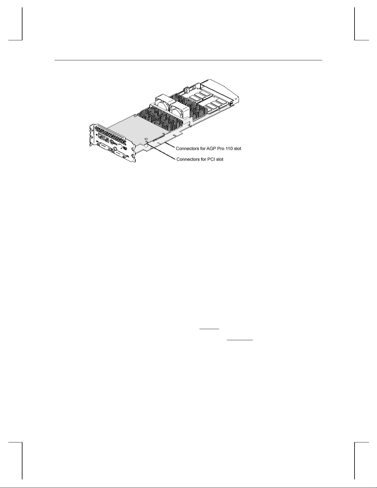
Figure 2. Expansion slots connectors
5. Push the card into the expansion slots firmly and evenly until it is fully seated in the slot
connectors.
6. Visually inspect the connections. If they do not appear to be correct, remove and reinstall the
card.
7. Use the screws you removed previously to secure the card to the computer’s chassis.
7
8. Close the computer and reconnect the power cord.
Connecting Monitors
Refer to the documentation delivered with the computer's monitors for information on the type of
connection required. The monitor cables will have either a Digital Video Interface (DVI)-I
connector or a 15-pin VGA connector.
To connect DVI monitors:
1. Turn off power to the computer and to the monitors.
2. Connect the cable for a single monitor to the Primary DVI-I port (see Figure 3).
3. If needed, connect the cable for a second monitor to the Secondary DVI-I port.
NOTE Multiple monitor support is available only under Windows 2000. If you are
connecting two monitors to the Wildcat 4210, see Chapter 3, “Using the W ildcat
4210,” for information about configuring dual displays.
4. Turn on power to the computer and to the monitors. If the monitors’ Power On LEDs do not
illuminate or the monitors do not display, refer to Chapter 4, “Troubleshooting.”
Page 14

8
Figure 3. DVI-I Ports
To connect VGA monitors:
1. Turn off power to the computer and to the monitors.
2. Connect the 15-pin VGA connector on each monitor cable to the VGA end of a DVI-VGA
adapter (see Figure 4).
3. If you are connecting a single monitor, connect the DVI-I end of the DVI-VGA adapter to the
Primary DVI-I port (see Figure 3).
4. If needed, connect the DVI-I end of the DVI-VGA adapter for a second monitor to the
Secondary DVI-I port.
NOTE Multiple monitor support is available only under Windows 2000. If you are
connecting two monitors to the Wildcat 4210, see Chapter 3, “Using the W ildcat
4210, “ for information about configuring dual displays.
Figure 4. DVI-I to VGA Adapter
5. Turn on power to the computer and to the monitors. If the monitors’ Power On LEDs do not
illuminate or the monitors do not display, refer to Chapter 4, “Troubleshooting.”
Page 15

NOTE If the computer’s monitors do not have built-in video cables, use shielded video
cables. The cables should have DVI-I connectors or 15-pin VGA connectors (with
adapters) at one end for the video output port on the card, and the appropriate
connectors at the other end for the video input ports on the monitors. See the
documentation delivered with the computer’s monitors for more information.
NOTE If you installed the Wildcat 4210 video card, the computer will boot into VGA mode.
Go to “Installing Wildcat Driver Software” for instructions on installing the Wildcat
driver software.
Installing Wildcat Driver Software
If you are installing or replacing a Wildcat 4210 card or reinstalling Wildcat driver software, take
the following steps.
Refer to the Microsoft Windows NT or Windows 2000 documentation and online Help for more
information on installing driver software.
Make Sure the Computer is Ready
Make sure the computer has the following before installing the Wildcat driver software:
9
♦ Microsoft Windows 2000 or Microsoft Windows NT Workstation 4.0 with Service Pack 5 (or
later)
♦ 3 MB of free space on the computer’s primary system disk
CAUTION You must have the correct driver for Windows 2000 or Windows NT 4.0. If you are
unsure, refer to the README file on the driver CD or diskette for this information.
Remove Existing Wildcat Driver Software
If you are reinstalling Wildcat driver software, you must first remove the currently installed
Wildcat driver software.
To remove Wildcat driver software in Windows 2000:
1. Log on to Windows 2000 using an account that has administrative privileges.
2. From the operating system Start menu, go to Settings » Control Pane l » Add/Remove
Programs » Change and Remove Programs.
3. Highlight the Intense3D Display Driver and click Change/Remove.
4. Click Yes when prompted to confirm driver software removal and follow the prompts.
5. Click OK when notified that driver software removal is complete.
6. Restart the computer.
Page 16

10
To remove Wildcat driver software in Windows NT 4.0:
1. Log on to Windows NT using an account that has administrative privileges.
2. From the operating system Start menu, go to Settings » Control Pane l » Add/Remove
Programs » Install/Uninstall.
3. Highlight the Intense3D Display Driver and click Add/Remove.
4. Click Yes when prompted to confirm driver software removal and follow the prompts.
5. Restart the computer.
Install Wildcat Driver Software
To install Wildcat driver software in Windows 2000:
1. Log on to Windows 2000 using an account that has administrative privileges.
2. When the Found New Hardware Wizard displays, click Next.
3. Under Install Hardware Device Drivers, click Search for a suitable driver for my device
(recommended), and then click Next.
4. Under Locate Driver Files, make sure the appropriate search location is selected, and that Disk
1 of the driver media is loaded in the appropriate drive (or the Disk 1 folder is selected); then
click Next. The Wizard locates the driver installation files.
5. Under Driver Files Search Results, click Next to start the installation.
6. Insert Disk 2 when prompted (or select the Disk 2 folder), and then click OK to continue with
the installation.
7. Once the driver successfully installs, click Finish to dismiss the Found New Hardware Wizard.
NOTE Windows 2000 recognizes the dual pipelines as two devices. The Found New
Hardware Wizard will display a second time to finish the installation. You must
repeat Steps 3 through 7 above to complete the installation.
8. When told that the computer must be restarted for the new settings to take effect, remove the
delivery media from the disk drive (if applicable) and click Yes to restart the computer.
See Chapter 3, “Using the Video Card,” for instructions on defining the display properties.
To install Wildcat driver software in Windows NT 4.0:
1. Log on to Windows NT using an account that has administrative privileges.
2. Insert the delivery media (diskettes or CD) into the appropriate device on the computer.
3. From the operating system Start menu, go to Settings » Control Panel » Display » Settings »
Display Type » Change.
4. In the Change Display dialog, click Have Disk.
Page 17

5. In the Install From Disk dialog, type the path to the directory that contains the delivery media.
6. In the Change Display dialog box, verify that the Wildcat 4210 driver is highlighted and then
click OK.
7. Click Yes when asked if you want to install a third-party driver.
8. After the driver files are copied, a message that the driver successfully installed displays.
Click OK.
9. Click Close to exit the Display Type dialog, and again to exit the Display Properties dialog.
10. When told that the computer must be restarted for the new settings to take effect, remove the
diskette from the computer’s floppy disk drive, if applicable. Click Yes to restart the
computer.
11. After the computer restarts and you log in, a message displays stating that a new display driver
has been installed, and that you should use the Display option in the Control Panel to select
the preferred display resolution. Click OK.
See Chapter 3, “Using the Video Card,” for instructions on defining the display properties.
Installing Heidi® Driver Software for AutoDesk Applications
11
The Intense3D Heidi driver software allows full-screen multisampling of and compatibility with
AutoDesk applications, as well as hardware acceleration of the Wildcat 4210 via OpenGL. To
install the Heidi driver software and to activate full screen multisampling, refer to the
on driver Disk 3 or in the Disk 3 folder of the driver CD.
Verify the Default Video Display Driver
To verify the default video display driver in Windows 2000:
1. From the operating system Start menu, go to Settings » Control Panel » Display » Settings.
2. Verify that two Intense3D Wildcat 4210 devices are listed under Display.
3. Click Cancel to close the Display Properties dialog.
See Chapter 3, “Using the Video Card,” for instructions on defining the display properties.
To verify the default video display driver in Windows NT 4.0:
1. From the operating system Start menu, go to Settings » Control Panel » Display » Settings »
Display Type.
2. Verify that Intense3D Wildcat 4210 is listed under Display.
3. Click Cancel to close the Display Properties dialog.
See Chapter 3, “Using the Video Card,” for instructions on defining the display properties.
README file
Page 18

12
Verify the System Startup Version
To verify the default system startup version in Windows NT 2000:
1. From the operating system Start menu, go t o Settings » Control Panel » System » Advanced »
Startup and Recovery.
2. Verify that Microsoft Windows 2000 Professional is listed as the default operating system and
click OK.
3. Click OK to close the System Properties dialog.
See Chapter 3, “Using the Video Card,” for instructions on defining the display properties.
To verify the default system startup version in Windo ws NT 4.0:
1. From the operating system Start menu, go to Settings » Control Panel » System »
Startup/Shutdown.
2. Verify that Windows NT Workstation Version 4.x is selected in the Startup list. If it is not,
select it from the list and click Apply.
NOTE Do not select the VGA version of the operating system. The video display runs in
VGA mode when the Wildcat driver software is not running.
3. Click OK to close the System dialog.
See Chapter 3, “Using the Video Card,” for instructions on defining the display properties.
Check the Video Image
To check the video image:
1. If the Display Properties dialog box is not already displayed, from the operating system Start
menu go to Settings » Control Pa nel » Display » Settings.
2. Click Test to test the display resolution.
3. Click OK to dismiss the Display Properties dialog.
See Chapter 3, “Using the Video Card,” for instructions on defining the display properties.
Page 19

Connecting a Stereo Display Device
See the documentation delivered with the stereoscopic display device for detailed information on
connections and cabling.
To connect a stereo display device:
1. Connect one end of the stereo emitter cable to the input port on the stereoscopic display
device.
2. Connect the other end of the stereo emitter cable to the Stereo Sync Out port on the Wildcat
4210 video card (see Figure 5).
3. Configure the display settings to enable stereo display. See Chapter 3, “Using the Video
Card,” for more information.
13
Figure 5. Stereo Sync Out Port
Page 20

14
Page 21

3 Using the Wildcat 4210
This chapter contains instructions for configuring the video display and enabling the stereo display.
If you purchased the Wildcat 4210 with a computer, it was configured for use before shipment.
Configuring the Video Display
On a computer running Windows NT 4 .0, the Display Propertie s dialog will have two additional
tabs: Intense3D Configuration and Intense3D Mo nitor. On a computer running Windows 2000, go
to Display Properties » Settings » Advanced to see these tabs.
To use the Intense3D Configuration tab:
1. Make sure you are logged into a non-VGA version of Windows NT or Windows 2000.
2. Close any open applications.
3. From the operating system Start menu, go to Settings » Control Panel » Display. In Windows
NT 4.0, click the Intense3D Configuration tab if it is not already displayed (see Figure 6). In
Windows 2000, continue to Settings » Advanced and click the Intense3D Configuration tab.
4. On the Intense3D Configuration tab, click Hardware Information to view hardware settings;
click View Configuration to view the display configuration; o r click Configurati on Wizard to
modify or delete the display configuration or create a new one.
15
Figure 6. Intense3D Configuration Tab
To use the Intense3D Monitor tab:
1. Make sure you are logged into a non-VGA version of Windows NT or Windows 2000.
Page 22

16
2. Close any open applications.
3. From the operating system Start menu, go to Settings » Control Panel » Display. In Windows
NT 4.0, click the Intense3D Monitor tab if it is not already displayed (see Figure 7). In
Windows 2000, continue to Settings » Advanced and click the Intense3D Monitor tab.
Figure 7. Intense3D Monitor Tab
4. In the Intense 3D Monitor tab, click Color Calibration to change the color settings (see Figure
8). Make changes, and then click OK to accept the changes and dismiss the Color Calibration
dialog, or click Cancel to close the Color Calibration dialog without making any changes.
You are returned to the Intense3D Monitor tab.
Figure 8. Color Calibration Dialog
Page 23

5. In the Intense3D Monitor tab, click Configure Monitor to change the display mode, select a
monitor type, and change the resolution/refresh rate (see Figure 9). Once you have made the
changes you require, click OK to accept the new configuration and dismiss the Configure
Monitor dialog. You are returned to the Intense3D Monitor tab.
NOTE See “Enabling Stereo Display,” for instructions on changing the Display Mode. See
Appendix A, “Specifications,” for a list of available monitor resolutions.
17
Figure 9. Configure Monitor Dialog
6. Click OK on the Display Properties dialog to accept the changes, or click Cancel to close the
dialog without accepting any modifications.
7. Restart the computer if you are prompted to do so. Most changes will take effect without
restarting.
Enabling Stereo Display
If you connect a device to the stereo port on the Wildcat 4210, you must change the display mode
to view in stereo.
To enable stereo display:
1. Make sure your stereo display device is properly connected to the stereo output port on the
Wildcat 4210. See Chapter 2, "Setup," for more information.
2. From the operating system Start menu, go to Settings » Control Panel » Display. In Windows
NT 4.0, click the Intense3D Monitor tab if it is not already displayed. In Windows 2000,
continue to Settings » Advanced and click the Intense3D Monitor tab.
3. On the Intense3D Monitor tab, click Configure Monitor.
4. Select a Stereoscopic Display mode from the Display Mode list box and then click OK.
Page 24

18
5. You may see the following message: “The selected monitor cannot display the current desktop
area. Select a new resolution before applying these changes.” If you do, click OK and then
select a resolution from the list of available resolutions.
6. Click OK if the display is correct and you wish to keep the new settings.
7. Click OK to accept the new display mode.
NOTE You must disable stereo mode when you no longer wish to view in stereo. Follow the
previous steps, and select Monoscopic Display from the Display Mode list box.
Enabling Multiview and Genlock
The Wildcat 4210 features Multiview support for frame locking and rate locking of multiple
computers. Genlock support allows video timing to be synchronized to an external timing source.
NOTE Your application must support Multiview for Multiview to work.
NOTE Refer to the Support pages on the Intense3D Web site for information on ordering
the correct Multiview and Genlock cables.
To prepare computers to use Multiview:
1. Insert one end of a shielded RJ12 cable into the Multiview Out port (see Figure 10) of the first
computer. This computer becomes the “master”
2. Insert the other end of the cable into the Multiview In port (see Figure 10) of the second
computer. This computer becomes a “slave.”
Figure 10. Multiview Ports
3. If connecting more tha n two computers, continue linking computers to one another by
connecting the Multiview Out port of one computer to the Multiview In port of the next. The
last computer should terminate the links and only have a cable plugged into the Multiview In
port.
Page 25

19
To confirm Multiview cables are detected:
1. On each "slave" computer, from the operating system Start menu, go to Settings » Control
Panel » Display » Settings.
2. If the computer is running Windows NT 4. 0, the input cables will display as Detected und er
Multiview Information.
3. If the computer is running Windows 2000, go to Advanced » Intense 3D Monitor » Multiview.
The input cables will display as Detected under Multiview Information.
To enable Genlock:
1. Connect the external timing source to the Genlock In port on the "master" computer (see
Figure 11).
Figure 11. Genlock In port
2. From the operating system Start menu, go to Settings » Control Panel » Display » Settings »
Advanced » Intense3D Monitor » Multiview (see Figure 12).
Figure 12. Multiview configuration dialog box.
3. Under Genlock Configuration, choose Enable
4. Choose the signal source from the Source list box.
Page 26

20
5. Select the Signal Edge Response, Signal Lock Rate, and Pixel Align Offset appropriate for
your application and hardware setup, and then click Apply.
NOTE Some monitors require custom timing file entries for Genlock to be properly
maintained. Refer to the documentation delivered with your monitor for further
information.
Enabling Dual Monitors in Windows 2000
Wildcat 4210 supports dual monitors on a computer running Windows 2000. Two monitors can
be connected to the Wildcat 4210 so the display area stretches across both monitors.
NOTE Before enabling dual monitors, connect the second monitor to the Secondary DVI-I
port. See Chapter 1, "Setup,” for instructions.
To enable dual monitors:
1. From the operating system Start menu, go to Settings » Control Panel » Display » Settings »
Advanced » Intense3D Configuration.
2. Next to Maximum Number of Displays, select 2, and then click Apply (see Figure 13).
Figure 13. Choosing Maximum Number of Displays
3. When prompted, click Yes to shut down the computer. When the computer has shut down,
turn off power to the computer.
4. Turn on power to the computer and to the monitors. The primary monitor displays the startup
sequence. If the monitors' Power On LEDs do not illuminate or the monitors do not display,
refer to Chapter 4, “Troubleshooting.”
Page 27
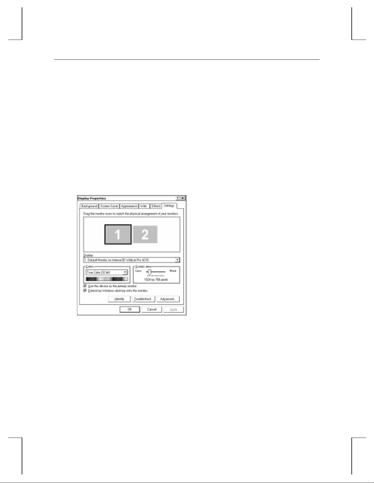
To change monitor settings with a dual monitor conf iguration:
1. From the operating system Start menu, go to Settings » Control Panel » Display » Settings.
2. Drag the monitor icons to match the physical arrangement of your monitors (see Figure 14).
3. Click OK.
To adjust the colors or resolution of a monitor:
1. From the operating system Start menu, go to Settings » Control Panel » Display » Settings.
2. Click the icon for a monitor or select that monitor from the Display list box (see Figure 14).
3. Make changes to the items under Colors or Screen Area.
4. Click OK.
NOTE Any changes made in the Advanced Properties dialog affects both monitors.
21
Figure 14. Dual Monitor Settings Tab
Page 28

22
Page 29

4 Troubleshooting
This chapter describes common problems and solutions, how to get a usable video resolution, how
to reinstall the video driver software, and how to get help.
Common Problems and Solutions
Problem Cause Solution
Display is black, not
synchronized, or
distorted
Display properties are not
set correctly.
Single monitor is not
plugged into primary DVI-I
port.
23
In Windows 2000, restart in Safe Mode
and select a supported resolution and
refresh rate. In Windows NT, use the
Last Known Good option. See "Getting
a Usable Video Resolution" later in this
chapter.
Turn off power to the computer.
Disconnect the monitor from the
secondary DVI-I port and connect it to
the primary DVI-I port. See Chapter 2,
"Setup," for more information.
Monitor does not support
a selected resolution or
refresh rate
There is no VGA boot
screen
The selected settings are
not compatible with your
monitor and video card.
The connections may not
be set up properly.
In Windows 2000, restart in Safe Mode
and select a supported resolution and
refresh rate. In Windows NT, use the
Last Known Good option. See "Getting
a Usable Video Resolution" later in this
chapter.
Reinstall the video driver. See Chapter
2, "Setup," for more information.
Make sure the monitor cables are
securely fastened to the video card.
Make sure the monitors and computer
are plugged i nto electrical outlets and
are receiving power.
Check any other external display
connectors, if applicable.
Make sure the video card is seated
properly in its expansion slot.
Page 30

24
Problem Cause Solution
Screen image is offcenter
Color balance is wrong Monitor settings may be
There is no picture
Screen image defects
appear
Diagnostics
Monitor settings may be
configured improperly.
configured improperly.
Improper software setup or
hardware problem.
Computer was not shut
down and powered off after
selecting the dual monitor
feature in Windows 2000.
Possible indication of a
hardware problem.
Refer to your monitor’s documentation
for instructio ns on making horizontal
and vertical adjustments.
Refer to your monitor’s documentation
for instructions on adjusting the color
display.
Restart into VGA/Safe Mode to verify
the display properties are configured
correctly for the monitor type. If the
software setup is correct, use a similar
type monitor (if available and
functioning properly) to determine if
the computer is defective. See “Getting
a Usable Video Resolution” later in this
chapter.
Shut down the computer and turn off
power to it. Then turn on power to the
computer and let it restart.
Run diagnostics to check the graphics
hardware.
Diagnostics utilities for checking the video card and instructions for using these utilities may be
available from your computer vendor.
Getting a Usable Video Resolution
The computer operates in VGA mod e when the video display driver is not running t o
accommodate all monitor types. VGA mode is used during initial installation of the video display
driver and when experiencing video problems. If you select a resolution that causes the monitor to
display incorrectly, take the following actions, as appropriate.
Page 31

In Windows 2000
Press CTRL+ALT+DEL but do not log on to the Windows 2000 operating system. Instead, shut
down the computer, and then restart into Safe Mode to choose another resolution or to reinstall the
video driver software.
To restart in Safe Mode:
1. Restart the computer.
25
2. At the boot screen, press
3. Select Safe Mode, and then press
In Windows NT 4.0
Press CTRL+ALT+DEL but do not log on to the Windows NT operating system. Instead, shut down
then use the Last Known Good option to return to the last known good configuration recorded by
Windows NT.
To use the Last Known Good option:
1. Restart the computer.
2. Press the space bar when prompted to invoke the Last Known Good menu.
If this option fails to correct the video display problem, restart the computer in VGA mode and
reconfigure your display to 640 x 480 resolution, 60 Hz refresh rate. Then restart the computer in
non-VGA mode.
To restart in VGA mode:
1. Restart the computer.
2. At the boot screen, select the VGA version of the operating system.
F8 to enter the Windows 2000 Advanced Options Menu.
ENTER to return to the boot screen.
Determining a Defective Unit
To determine a defective unit:
1. Save and exit from all files.
2. Shut down the operating system.
3. Turn off the power to the monitor and to the computer.
CAUTION Always turn off the power to the computer before connecting or disconnecting the
cables.
4. Check and reseat all card and cable connections as needed.
Page 32

26
5. Turn on the monitor power. If the Power On LED does not illuminate, see "Getting Help" in
this chapter.
6. Turn on the power to the computer base unit. If the Power On LED on the base unit does not
illuminate, or if the BIOS beep codes indicate a failure, see "Getting Help" in this chapter.
Getting Help
If the troubleshooting procedures in this chapter do not resolve the problem, please contact your
computer vendor for technical assistance. For information about your warranty, see your
computer’s documentation.
Page 33

5 Technical Information
Functional Specifications
♦ Interface – AGP Pro 110
♦ Graphic controller – High-speed Wildcat chipset technology
♦ DAC speed – 250 MHz
♦ Data width – Frame buffer 256 bits; texture buffer 128 bits; DirectBurst 64 bits
♦ Video memory – Frame buffer 128 MB; texture buffer 128 MB; DirectBurst 32 MB
♦ Interrupts – PCI-assigned; Interrupt A for Wildcat 4210
♦ DMA chann els – PCI, AGP 2x
♦ Connectors – Two DVI-I outputs; BNC connector; two 6-pin modular jacks; 3-pin miniDIN
stereo sync output
♦ Dimensions – 2.20 in (5.6 cm) high x 13.34 in (33.9 cm) long by 4.25 in (10.8 cm) wide
27
Requirements
♦ Expansion slots – One AGP Pro 110 slot and two adjacent PCI slots (one for the on-board
power supply and one for cooling)
♦ Power – 85 W maximum; 12.0 V 250 mA maximum; 5.0 V 9.8 A maximum; 3.3 V 10 A
maximum
3D Performance
Performance numbers reflect maximum hardware rate. Numbers may vary depending on the
application.
♦ 3D Gourad-shaded triangles, Z-buffered, 15-pixel – 12.0 M triangles/sec
♦ 3D Gourad-shaded triangles, Z-buffered, 25-pixel – 8.5 M triangles/sec
♦ 3D Vectors, solid color, 10-pixel – 17.6 M vectors/sec
Page 34

28
Resolutions and Refresh Rates
Supported monitor resolutions and refresh rates may vary depending on the monitor.
Monitor Resolutions
(bits per pixel)
1280 x 1024 85 Yes Yes
1920 x 1440 75 - 1856 x 1392 85 - 1824 x 1368 90 - 1792 x 1344 75 - 1600 x 1200 90 Yes 1280 x 960 85 Yes Yes
1152 x 864 85 Yes Yes
1024 x 768 85 Yes Yes
800 x 600 85 Yes Yes
640 x 480 85 Yes Yes
1920 x 1200 76 - 1824 x 1128 75 Yes 1792 x 1120 75 Yes 1600 x 1024 76 Yes 1440 x 900 90 Yes Yes
1280 x 800 90 Yes Yes
2048 x 1152 75 - 1920 x 1080 85 Yes 1600 x 900 85 Yes 1520 x 856 90 Yes Yes
1360 x 766 90 Yes Yes
1280 x 720 85 Yes Yes
856 x 480 85 Yes Yes
Max. Refresh
Rates (Hz)
SuperSceneAAFrame Sequential
Stereo
Page 35

Connectors
The Wildcat 4210 is an AGP Pro 110 card designed for computers that have an AGP Pro 110 slot.
The card plugs into the AGP Pro 110 slot and an adjacent PCI slot.
NOTE A Wildcat 4210 cannot plug into a standard AGP slot.
Figure 15. Expansion slot connectors
29
The card has several external ports for external devices and computer connections. The following
sections describe the ports in detail.
Figure 16. External connectors
Page 36

30
DVI-I Out Ports
The primary and secondary digital video output ports are DVI-I receptacles with 29 signal contacts
as specified by the Digital Visual Interface specification (Revision 1.0). These ports support pixel
rates up to 112 MHz using the SII150 A PanelLink device from Silicon Image. The ports are fully
compliant with the DVI specification, and support digital and analog displays.
Genlock In Port
This port is a 75-ohm male BNC connector that is used to connect to a 75-ohm coaxial cable
terminated with a female BNC connector. The port allows video timing to be synchronized to an
external timing source. The port provides a periodic signal to the display system to lock vertical
refresh rate.
Stereo Sync Out Port
This port is a female, 3-pin, mini-DIN connector. The port provides connection to the emitter
module for LCD shutter glasses or to other stereo shutter devices.
Multiview In and Out Ports
These ports are two 6-pin modular jack connectors. They allow Multiview support for frame
locking and rate locking of multiple computers.
 Loading...