

Page 1

Intense3D
Wildcat 3510 Graphics
Hardware User’s Guide
June 1999
D1AV00050
Page 2

Copyright
1999 Intense3D, Inc. All rights reserved. This document contains information protected by copyright, trade secret, and trademark
law. This document may not, in whole or in part, be reproduced in any form or by any means, or be used to make any derivative
work, without written consent from Intense3D.
Use, duplication, or disclosure by the United States Government is subject to restrictions as set forth in subdivision (c)(1)(ii) of the
rights in technical data and computer software clause at DFARS 252.227-7013. Unpublished rights are reserved under the copyright
laws of the United States.
Intense3D, Inc., Huntsville AL 35894-0001
Notice
Information in this document is subject to change without notice and should not be considered a commitment by Intense3D.
Intense3D shall not be liable for technical or editorial errors in, or omissions from, this document. Intense3D sh all not be liable for
incidental or consequential damages resulting from the furnishing or use of this document.
All warranties given by Intense3D about equipment or software are set forth in your purchase contract. Nothing stated in, or implied
by, this document or its contents shall be considered or deemed a modification or amendment of such warranties.
Trademarks
Intense3D and the Intense3D logo are registered trademarks and Wildcat is a trademark of Intense3D, Inc. Microsoft and Windows
NT are registered trademarks of Microsoft Corporation. Intel and Pentium are registered trademarks of Intel Corporation. Other
brands and product names are trademarks of their respective owners.
FCC/DOC Compliance
This equipment has been tested and found to comply with the limits for a Class B digital device, pursuant to part 15 of the FCC
Rules. These limits are d esigned to pr ovide reasonable protectio n against harmful interference when the equip ment is operated in a
residential installation. This equipment generates, uses, and can radiate radio frequency energy. If the equipment is not installed and
used in accordance with the instructions, it may cause harmful interference to radio communications. However, there is no guarantee
that interference will not occur in a particular installation.
If this equipment does cause harmful interference to radio or television reception, which can be determined by turning the equipment
off and on, try to correct the interference as follows: reorient or relocate the affected device; increase the separation between this
equipment and the affected device; connect this equipment to an outlet on a circuit different from the circuit to which the affected
device is connected; consult a dealer or an experienced radio/television technician for help.
This Class B digital apparatus meets all requirements of the Canadian Interference-Causing Equipment Regulations. Cet appareil
numérique de la classe B respecte toutes les exigencies du Règlement sur le materiél brouilleur du Canada.
Warnings
Changes or modifications made to the system that are not approved by the party responsible for compliance could void the user's
authority to operate the equipment.
To reduce the risk of electrical shock, do not attempt to open the equipment unless instructed. Do not use a tool for purposes other
than instructed.
Notes
This device is designed and manufactured to comply with approved safety standards for information processing and business
equipment.
Read all operating instructions before using this device. Keep these instructions for future reference. Follow all warnings on the
device or in the operating instructions.
Page 3

Contents
Preface........................................................................................................................ ..................... v
About This Document.......................................................................................................................v
Document Conventions..................................................................................................................... v
Operating System Information.......................................................................................................... v
Customer Support ............................................................................................................................ vi
1 Getting Started.............................................................................................................................1
System Requirements........................................................................................................................1
Features.............................................................................................................................................1
Hardware.......................................................................................................................................... 2
Driver Software................................................................................................................................ 2
Connecting Monitors........................................................................................................................ 2
Configuring the Video Display.........................................................................................................3
Enabling the Stereo Display............................................................................................................. 4
iii
Hardware and Software Support Services......................................................................... vi
World Wide Web .............................................................................................................. vi
Intergraph Bulletin Board Service..................................................................................... vi
Telephone.........................................................................................................................vii
More Support Options...................................................................................................... vii
2 Replacing and Upgrading the Wildcat 3510 Graphics Card.................................................. 5
Taking Antistatic Precautions........................................................................................................... 5
Collecting Materials and Tools......................................................................................................... 5
Removing and Installing Cards......................................................................................................... 6
Finishing the Installation...................................................................................................................7
Installing Driver Software.................................................................................................................7
Troubleshooting the Installation....................................................................................................... 8
3 Technical Information............................................................................................................... 11
Hardware Specifications................................................................................................................. 11
Monitor Resolutions.......................................................................................................................11
VGA Video Display Support.......................................................................................................... 12
Texture Processing ......................................................................................................................... 12
DDC and DPMS Support ............................................................................................................... 12
Interfaces........................................................................................................................................ 13
Video Output Port............................................................................................................ 13
Stereo Sync Output Port................................................................................................... 14
Page 4

iv
Page 5

Preface
The Intense3D Wildcat 3510 Graphics Hardware User’s Guide provides information and
technical specifications on the Intense3D Wildcat 3510 graphics accelerator.
About This Document
The Intense3D Wildcat 3510 Graphics Hardware User’s Guide is organized as follows:
♦ Chapter 1, “Getting Started,” introduces the Wildcat 3510 and its features, and describes how
to get started using the Wildcat 3510 in your workstation.
♦ Chapter 2, “Replacing and Upgrading the Wildcat 3510,” provides instructions for replacing
Wildcat 3510 hardware, installing cards, reinstalling driver software, and troubleshooting the
installation.
♦ Chapter 3, “Technical Information,” provides technical information about the Wildcat 3510.
Document Conventions
v
Bold
Italic Variable values that you supply, or cross-references.
Monospace
SMALL CAPS Key names on the keyboard, such as D, ALT or F3; names of files and directories.
CTRL+D Press a key while simultaneously pressing another key; for example, press CTRL
Commands, words, or characters that you key in literally.
Output that displays on the screen.
You can type filenames and directory names in the dialog boxes or the command
line in lowercase unless directed otherwise.
and D simultaneously.
Operating System Information
For more detailed information on the Microsoft Windows NT® operating system, refer to the
printed and online Microsoft documentation delivered with the system.
Page 6

vi
Customer Support
Intergraph Computer Systems offers an assortment of customer support options.
Hardware and Software Support Services
Intergraph Computer Systems provides a variety of hardware services for Intergraph and thirdparty equipment. Services include warranty upgrades, repair depot service, on-site hardware
maintenance, system administration, and network co nsulting. Hardware purchased from Intergraph
Computer Systems includes a factory warranty ranging from 30 days to three years. A detailed
warranty description is available on the World Wide Web; see the Support pages at
http://www.intergraph.com/ics.
Intergraph Computer Systems provides complimentary software support for 30 or 90 days
following shipment of a hardware or software product. This includes World Wide Web access,
Intergraph Bulletin Board Service access, and telephone (Help Desk) support. At the end of the
complimentary support period, you can purchase other levels of software support.
World Wide Web
You can visit Intergraph Computer Systems’ Support page on the World Wide Web at
http://www.intergraph.com/ics. On these pages, you can get news and product information,
technical support information, software updates and fixes, and more.
For the latest Intense3D news and product information, visit Intense3D on the World Wide Web at
http://www.intense3d.com.
Intergraph Bulletin Board Service
On the Intergraph Bulletin Board Service (IBBS), you can get technical support information,
software updates and fixes, and more.
To connect to the IBBS:
1. Set your system’s communications protocol for eight (8) data bits, no parity, one (1) stop bit,
and any baud rate up to 14,400.
2. Using a modem, call 1-256-730-8786. Outside the United States, call one of the mirror sites
listed on World Wide Web; see the Software Support pages at http://www.intergraph.com.
3. At the login prompt, key in your user ID. If you have not connected before, key in new to
create a user ID.
4. Follow the menus to find what you need. The IBBS provides clear choices and online help.
Page 7

If you have trouble conne cting to or using the IBBS, call the Customer Response Center at
1-800-633-7248 (product entry IBBS) or leave a message for the IBBS System Operator at
1-256-730-1413.
Telephone
To get customer support by telephone:
♦ In the United States, call the Customer Response Center at 1-800-633-7248 between the hours
♦ Outside the United States, contact your local Intergraph Computer Systems subsidiary or
Have the following information available when you call:
♦ Your service number, which identifies your site to Intergraph Computer Systems. You use
♦ Your Customer Personal Identification Number (CPIN). You get a CPIN the first time you
♦ The product’s name or model number.
vii
of 7:00 a.m. and 7:00 p.m. Central Time, Monday through Friday (except holidays).
distributor.
your service number for warranty or maintena nce calls.
call the Customer Response Center; it is associated with your service number for future call
logging.
♦ The product’s serial number. Software product serial numbers are included in the product
packaging. Hardware product serial numbers are on a sticker affixed to the hardware product.
♦ Your name and telephone number.
♦ A brief description of the question or problem.
More Support Options
For information on more customer support options:
♦ Visit the Support pages on the World Wide Web at http://www.intergraph.com/ics.
♦ For hardware support questions in the United States, call 1-800-763-0242.
♦ For software support questions in the United States, call 1-800-345-4856.
♦ Outside the United States, contact your local Intergraph Computer Systems subsidiary or
distributor.
Page 8

viii
Page 9

1 Getting Started
This chapter introduces the Wildcat 3510 graphics accelerator and describes what you need to use
it in your workstation.
System Requirements
To use the Wildcat 3510, you will need:
♦ A workstation running on Intel’s Pentium
®
♦ Microsoft Windows NT
optimal performance on systems using Intel’s Pentium III processor)
♦ A full-length Advanced Graphics Port (AGP) slot to insert the Wildcat 3510
♦ A minimum of 32 MB DRAM (64 MB recommended)
♦ An industry-standard, multiple-frequency monitor
♦ 3 MB of free space on the computer’s primary system disk for the Wildcat 3510 video display
driver software
Workstation 4.0 operating system (with SSE/SIMD extensions for
®
II (or later) processor or equivalent
1
Features
The Wildcat 3510 offers the following high-end graphics features.
♦ Support for Windows NT graphics – Graphic Device Interface (GDI) and OpenGL
♦ Support for resolutions up to 1.3 megapixels (1280 x 1024)
♦ Support for graphics features such as Gouraud shading, 2D and 3D vectors and triangles,
texture processing, rectangle fills, antialiased vectors, clipping, alpha blending, fog, and
stenciling
♦ 16 MB of Synchronous Dynamic RAM (SDRAM) frame buffer memory and 16 MB of
SDRAM texture memory
♦ Video plane sets of 128 bits per pixel (up to 1152 x 864) and 100 bits per pixel (at 1280 x
1024)
♦ Four video lookup tables
♦ 10-bit gamma correction
♦ 32-bit double-buffering and 32-bit Z-buffering at 128 bits per pixel (up to 1152 x 864) or 24-
bit double-buffering and 24-bit Z-buffering at 100 bits per pixel (at 1280 x 1024)
♦ Integrated VGA video support
Page 10

2
♦ Support for industry-standard monitors
♦ Hardware support for stereoscopic viewing, Display Data Channel (DDC), and Display Power
Management Signaling (DPMS)
Visit http://www.intense3d.com for the latest performance data and other product information.
Hardware
The Wildcat 3510 is a single-card solution that uses one AGP slot in your workstation.
Driver Software
The Wildcat 3510 uses the Intense3D Wildcat video display driver. The video display driver
installs as a standard Windows NT driver, and provides both GDI and OpenGL graphics
compatibility. In a workstation purchased with the Wildcat 3510, the current driver is installed on
your workstation, and is delivered on backup media with the system. You can download updated
drivers from Intergraph Computer Systems’ Web pages; see the Preface of this document for more
information.
Connecting Monitors
In a workstation purchased with the Wildcat 3510, the appropriate card is already installed in the
workstation base unit.
To connect monitors to the Wildcat 3510:
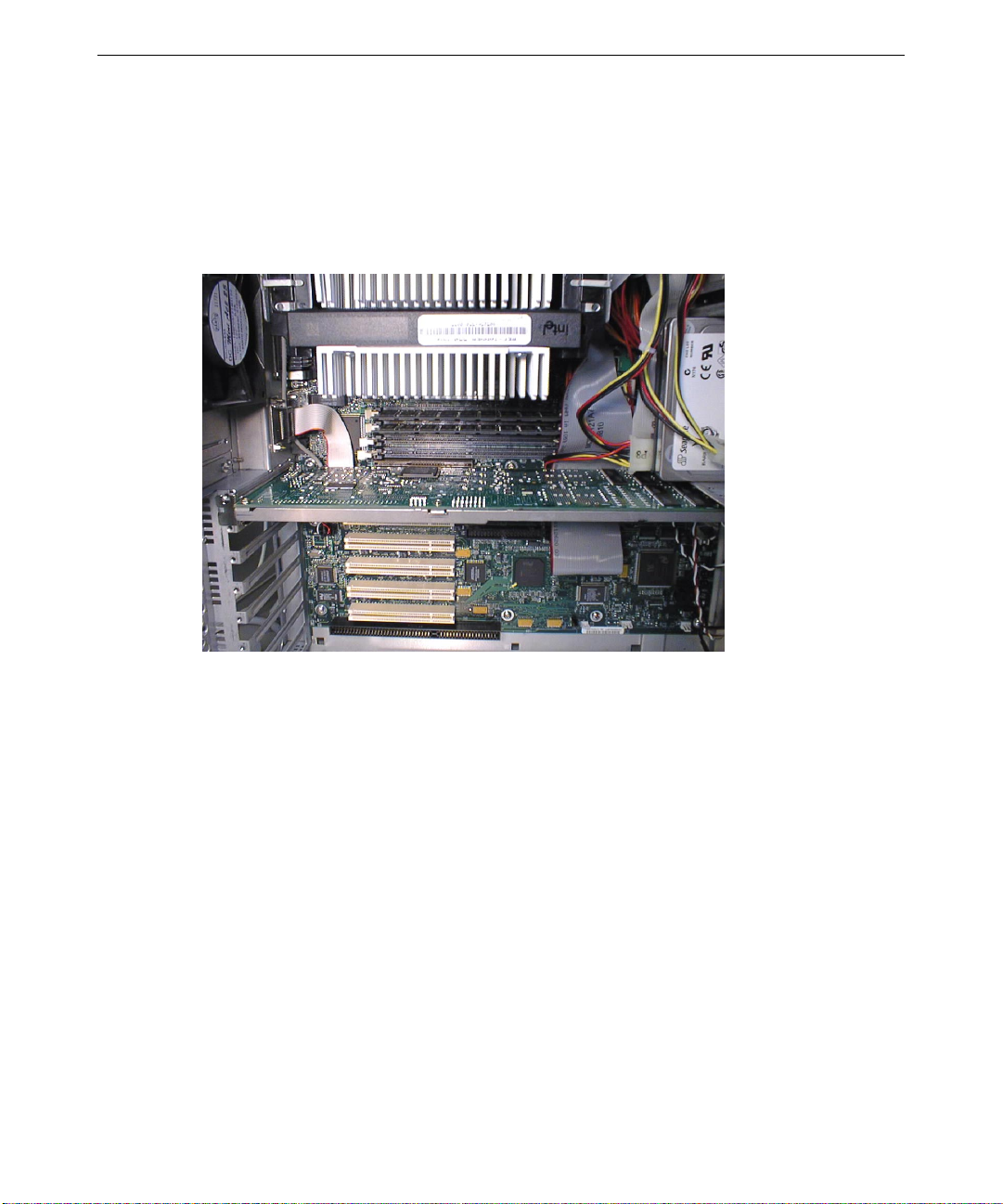
1. Connect the workstation monitor’s video cable to the color video output por t on the Wildcat
3510 card. See the following figure. (Insert new figure.)
Video Output Stereo Sync
Port Output Port
Page 11

NOTE If a workstation monitor has no built-in video cable, use a shielded video cable with a
15-pin (D-sub) video connector at one end for the video output port on the card, and
the appropriate connectors at the other end for the video input port on the
workstation monitor.
Monitor input ports are usually D-sub or Bayonet Nut Connect (BNC) connectors.
Shielded cables usually have a ferrite core (a box- or cylinder-shaped attachment)
near each end to reduce interference with radio frequencies.
2. Turn on power to the workstation. The video display starts in VGA mode.
3. If you want to use a stereoscopic display device, see the previous figure and the section in this
chapter on enabling the stereo display.
Configuring the Video Display
After connecting the monitor, you can turn on system power, start the Windows NT operating
system, and configure the video display.
CAUTION Make sure the monitor is connected correctly to the Wildcat 3510 before applying
power to the monitor and to the workstation.
To start the Microsoft Windows NT operating system:
3
1. Turn on power to the monitor and to the workstation.
2. At the boot screen, select the non-VGA version of Windows NT.
3. When prompted, press
CTRL+ALT+DEL to log on to Windows NT.
4. Log on to Windows NT. Refer to Windows NT documentation and Help for instructions, if
necessary.
To enable your workstation to use the Wildcat 3510, you must configure the display properties of
the Wildcat 3510 driver software. The driver software is installed on the system’s primary hard
disk drive. The Display Properties dialog is available from the Windows NT Control P a nel to
determine the system configuration and installed options. Display Properties lets you change the
video display settings to meet your needs.
To configure Wildcat 3510 video display driver software:
1. Close all open applications.
2. From the operating system Start menu, go to Settings/Control Panel/Display.
NOTE Two
Intense3D
Intense3D
tabs appear in the Display Properties Dialog:
Monitor. See Chapter 2 for details on how to use these tabs.
Intense3D
Settings and
3. Use the Display Properties dialog tabs to configure the operation of the workstation’s video
display. For example, click the Settings tab to change the screen resolution.
Page 12

4
4. Click OK to close the Display Properties dialog, or click Cancel to close Display Properties
without applying the changes.
5. Restart the system for changes to video attribute settings to take effect. (Certain changes, such
as gamma correction, do not require that you restart the system.)
For more detailed configuration information, see Chapter 2 and the
delivery media containing the Wildcat 3510 video display driver.
After you configure the video display, verify that the Wildcat 3510 driver is the default video
display driver that runs automatically when you start the workstation.
To verify the default video display driv er:
1. From the operating system Start menu, go to Settings/Control Panel/System.
2. On the Startup/Shutdown tab, verify that the non-VGA version of Windows NT is selected in
the Startup list. If it is not, select it from the list and click Apply.
3. Click OK to close the System dialog.
NOTE Do not select the VGA version of the operating system. The video display runs in
VGA mode when the Wildcat 3510 driver is not running.
Enabling the Stereo Display
The Wildcat 3510 provides a female, 5-pin stereo port for connecting a pair of LCD shutter glasses
and emitter module. Follow these instructions to connect the stereo emitter and enable the stereo
display:
1. Connect the stereo emitter cable to the stereo sync output port on the Wildcat 3510.
2. From the operating system Start menu, go to Settings/Control Panel/Display.
README.TXT file on the
3. Select Intense3D settings. Then select Advanced.
4. Select Enable Stereo Display and your choice of sequential or interlaced mode.
5. When prompted, restart your workstation. A red light on the stereo emitter indicates that your
display is configured for stereo and Microsoft Windows NT is running.
NOTE You must disable stereo mode when you no longer wish to view in stereo.
Page 13

2 Replacing and Upgrading the Wildcat 3510
Graphics Card
Follow the instructions in this chapter if you must replace or upgrade the Wildcat 3510 in your
workstation. Refer to your workstation’s documentation for instructions on opening and closing
the system and identifying the AGP expansion slot.
Taking Antistatic Precautions
Static electricity can damage the components inside a computer or on a printed circuit card. To
reduce the possibility of electrostatic discharge:
♦ Turn off power to the computer.
♦ Touch the metal chassis of the computer to drain off any static electricity before touching a
card.
♦ Wear a properly connected gro unding wrist strap when handling a card or working in a
computer.
♦ Do not wear wool or polyester clothing.
5
♦ Work in an area with a relative humidity of at least 50 percent.
♦ Keep cards in anti-static bags until you are ready to install them.
♦ Handle cards as little as possible and by the edges only.
Collecting Materials and Tools
Make sure you have the following materials and tools, as appropriate:
♦ Intense3D Wildcat 3510 card
♦ Backup media containing the Intense3D Wildcat 3510 video display driver (delivered with the
system), unless you plan to download an updated driver from Intergraph Computer Systems’
Webs pages (see the Preface of this document for more information)
♦ Flat-head or Phillips screwdriver, if required
Page 14
6
Removing and Installing Cards
To remove an installed Intense3D Wildcat 3510 card:
1. Turn off power to the workstation and to the monitor.
2. Open the workstation to gain access to the AGP slot.
3. Remove the existing card. Keep the screws; you will use them to secure the card to the
workstation’s chassis later.
To install the Intense3D Wildcat 3510 card:
1. Align the card with the AGP expansion slot, making sure the gold-fingered connections on the
card’s edge are aligned properly with the slot connector.
2. Push the card into the AGP slot firmly and evenly until it is fully seated in the AGP slot
connector.
3. Visually inspect the connection. If it does not appear to be correct, remove and reinstall the
card.
4. Use the screws you removed previously to secure the card to the workstation’s chassis.
Page 15

Finishing the Installation
To finish the installation:
1. Close the workstation.
2. Connect the workstation’s monitor as described in Chapter 1.
Installing Driver Software
You can install the Intense3D Wildcat video display driver software from the backup media
delivered with the system. You can also get updated driver software from Intergraph Computer
Systems’ Web pages; see the Preface of this document for more information. Refer to the
Microsoft Windows NT documentation and online Help for more information on installing drivers
and software application programs, and on configuring your workstation’s video display.
Make sure your workstation has the following before attempting to install Wildcat driver software:
♦ Microsoft Windows NT Workstation 4.0 operating system
♦ 3 MB of free space on the computer’s primary system disk
7
CAUTION Make sure you have the correct driver to use with the Windows NT 4.0 operating
system. If you are unsure, refer to the README.TXT file located on the delivery media
for this information.
To install Intense3D Wildcat 3510 driver software:
1. Log on to Windows NT using an account that has administrative privileges.
2. Create a directory on the workstation’s primary system disk.
3. Copy the files from the backup media to the directory created in step 2, or download them to
that directory from Intergraph Computer Systems’ Web pages.
4. From the operating system Start menu, go to Settings/Control Panel/Display/Settings.
5. Click Display Type, and then click Change.
6. In the Change Display dialog, click Have Disk.
7. In the Install From Disk dialog, type the path to the directory that you created in step 2 and
click OK.
8. Verify that the Wildcat 3510 driver is highlighted in the Change Display dialog and click OK.
Page 16

8
9. Click Yes when asked if you want to install a third-party driver. The files are copied from the
directory on your workstation’s primary hard disk drive.
NOTE If the driver files were delivered on two floppy diskettes, you will be prompted to key
in the path for the driver files from the second diskette. The files are copied from the
directory on your workstation’s primary hard disk drive.
10. After the driver files are successfully copied, a message that the driver successfully installed
displays. Click OK.
11. Click Close to exit the Display Type dialog.
12. Click Close to exit the Display Properties dialog.
13. When told that the workstation must be restarted for the new settings to take effect, remove
the diskette from the workstation’s floppy disk drive, if applicable. Click Yes to restart the
workstation.
14. After the system restarts and you log in, a message displays. The message states that a new
display driver has been installed, and that you should use the Display option in the Control
Panel to select the preferred display resolution. (See the section on monitor resolutions in
Chapter 3.) Click OK.
NOTE Two Intense3D tabs appear in the Display Properties Dialog: Intense3D Settings and
Intense3D Monitor. Use the Intense3D Settings tab to select graphics performance
and stereo settings. Use the Intense3D Monitor Type to select your monitor type and
review the supported DDC timings (if you have selected a DDC monitor).
15. Test your selected resolution by checking the Test option in the Display Properties dialog.
16. To change the display resolution or other display settings, see the section on configuring the
video display in Chapter 1. For more detailed installation information, refer to the
README.TXT file located on the delivery media.
CAUTION When you select Display in the Windows NT Control Panel, a message displays.
Click OK to close the message. The message displays every time you select Display
unless you clear the Show warning checkbox at startup.
Troubleshooting the Installation
The following table lists some common video configuration problems.
Problem
Display is black, not synchronized, or
distorted.
Monitor does not support a selected resolution
or refresh rate.
Action
Restart Windows NT in VGA mode and select a
supported resolution and refresh rate.
Restart Windows NT in VGA mode and select a
supported resolution and refresh rate.
Page 17

The system operates in VGA mode when the video display driver is not running to accommodate
all monitor types. VGA mode is used during initial installation of the video display driver and
when experiencing video problems. If you select a resolution that causes the monitor to display
incorrectly, do not press
CTRL+ALT+DEL to log on to the Windows NT operating system. Instead,
use the Last Known Good option to return to the last known good configuration recorded by
Windows NT.
To use the Last Known Good option:
1. Restart the system.
2. Press the space bar at the following prompt:
Press space bar NOW to invoke the Last Known Good Menu
If using the Last Known Good option fails to correct the video display problems, restart the system
in VGA mode and reconfigure your display to 640 x 480 x 60 Hz. Then, restart Windows NT
again in non-VGA mode.
To restart the system in VGA mode:
1. Restart the system.
2. At the boot screen, select the VGA version of the operating system.
9
If the monitor display is distorted, ensure the software setup is correct for the monitor type. If the
software setup is correct, use a similar type monitor (if available and functioning properly) to
determine if the workstation is defective.
To determine a defective unit:
1. Save and exit from all files, if possible; then shut down Windows NT.
2. Turn off the power to the monitor and to the workstation.
CAUTION Always turn off the power to the workstation before connecting or disconnecting the
cables.
3. Check and reseat all card and cable connections as needed.
4. Turn on the monitor power. If the Power On LED does not illuminate, return the monitor.
5. Turn on the power to the system base unit. If the Power On LED on the base unit does not
illuminate, or if the BIOS beep codes indicate a failure, return the workstation.
Page 18

10
Page 19

3 Technical Information
The following technical information is subject to change without notice.
Hardware Specifications
11
Item
System AGP 2.0
Card Size Full-length AGP card
Specification
Monitor Resolutions
In the following tables, i indicates an interlaced frequency.
The Wildcat 3510 supports standard multiple-frequency monitors at the following resolutions and
maximum refresh rates (Hz).
Resolution
640 x 480 4 x 3 128
800 x 600 4 x 3 128
1024 x 768 4 x 3 128
1152 x 864 4 x 3 128
1280 x 960 4 x 3 100
1280 x 1024 5 x 4 100
The Wildcat 3510 supports the following frame sequential stereo resolutions and maximum refresh rates for
multiple-frequency monitors.
Aspect Ratio Bits Per Pixel Vertical Refresh Rates (Hz)
60, 72, 75, 85, 60i
60, 72, 75, 85, 60i
60, 70, 75, 85, 60i
60, 70, 75, 85, 60i
60, 75, 85, 60i
60, 75, 85, 60i
Resolution
640 x 480 4 x 3 128 60
800 x 600 4 x 3 128 60
Aspect Ratio Bits Per Pixel Vertical Refresh Rates (Hz)
Page 20

12
The Wildcat 3510 supports InterView 28hd96 monitors at the following resolutions and maximum
refresh rates (Hz).
Resolution
640 x 480 4 x 3 128 75
800 x 600 4 x 3 128 75
1024 x 768 4 x 3 128 75
856 x 480 16 x 9 128 50, 60, 75
1280 x 720 16 x 9 128 50, 60, 75
1360 x 766 16 x 9 100
1520 x 856 16 x 9 100
The Wildcat 3510 supports Sony GDM-W900 monitors at the following resolutions and maximum
refresh rates (Hz).
Resolution
640 x 480 4 x 3 128 60
1280 x 1024 5 x 4 100 75
1280 x 800 16 x 10 128
1440 x 900 16 x 10 100
Aspect Ratio Bits Per Pixel Vertical Refresh Rates (Hz)
Aspect Ratio Bits Per Pixel Vertical Refresh Rates (Hz)
VGA Video Display Support
The Wildcat 3510 provides onboard VGA video display support. The maximum resolution
supported is 640 x 480, 4 bits per pixel, at 60 Hz vertical refresh.
72, 75, 85, 90, 60i
60, 70, 75, 85, 60i
60, 75, 85, 90, 60i
60, 75, 85, 60i
Texture Processing
The Wildcat 3510 provides full texture processing capabilities, including tri-linear interpolation of
MIP-mapped images. Included on the board are 16 MB of texture memory.
DDC and DPMS Support
The Wildcat 3510 provides hardware support for the Display Data Channel (DDC) standard for
communication between a workstation and its monitor. The Wildcat 3510 supports the DDC2B
standard, which allows for bidirectional communication.
Page 21

The Wildcat 3510 also provides hardware support for the Display Power Management Signaling
(DPMS) standard. DPMS allows for a workstation to send its monitor a signal to enter a powersaving mode.
Interfaces
The Wildcat 3510 has two interfaces: a video output port and a stereo sync output port. These
interfaces are described in the following sections.
Video Output Port
The video output port is a blue, female, 15-pin, D-Sub connector. The port provides connection to
a workstation monitor. The recommended cable length is less than three meters.
13
Pin
1 Red Analog Video 9 +5V Supply
2 Green Analog Video 10 Ground
3 Blue Analog Video 11 Monitor ID (bit 0)
4 Monitor ID (bit 2) 12 Monitor ID (bit 1) *
5 Ground 13 Horizontal /Composite Sync
6 Ground 14 Ver tical Sync
7 Ground 15 Monitor ID (bit 3) **
8 Ground
* Bidirectional Data (SDA) for DDC
** Data Clock (SCL) for DDC
Signal Name Pin Signal Name
11
1
6
Page 22

14
Stereo Sync Output Port
The stereo sync output port is a female, 5-pin, mini-DIN connector. The port provides connection
to the emitter module of a pair of LCD shutter glasses or to other stereo shutter devices.
Pin
Signal Name
1 Ground
2 Ground
3 +12V
4Stereo Sync
5 No Connect
5
x
3
1
4
2
 Loading...