

Page 1
USER’S MANUAL
PCI Express PEX Series
Interface Module
1-Channel RS-232C Asynchronous Serial Communications
and 1-Channel Printer Input/Output PCI Express Product
(Product Model: PEX-400111)
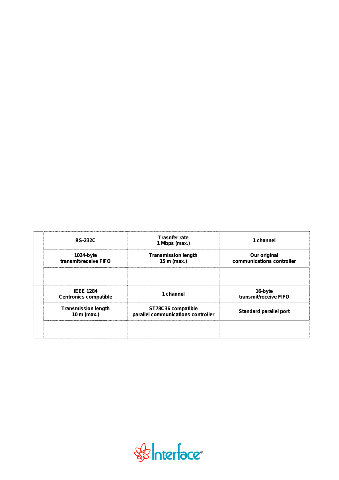
RS-232C
Trasnfer rate
1 Mbps (max.)
1 channel
1024-byte
Serial
Parallel
transmit/receive FIFO
IEEE 1284
Centroni cs co mpat i ble
Transmission length
10 m (max.)
Transmission length
15 m (max.)
1 channel
ST78C36 compatible
parallel communications controller
Our original
communic atio n s cont ro ller
16-byte
transmit/receive FIFO
Standard parallel port
Page 2
Notes to Users
You should carefully read Handle with Care for your safety before using this product.
The specifications of the product are under continuous improvement and while every effort is made to keep
this manual up-to-date, we reserve the right to update the contents of this
notice.
Therefore, you should thoroughly read this
product before.
All official specifications are expressed in metric. English unit is supplied for convenience. Using this product
requires t ech nica l know le dge o f har dwa re an d sof twa re.
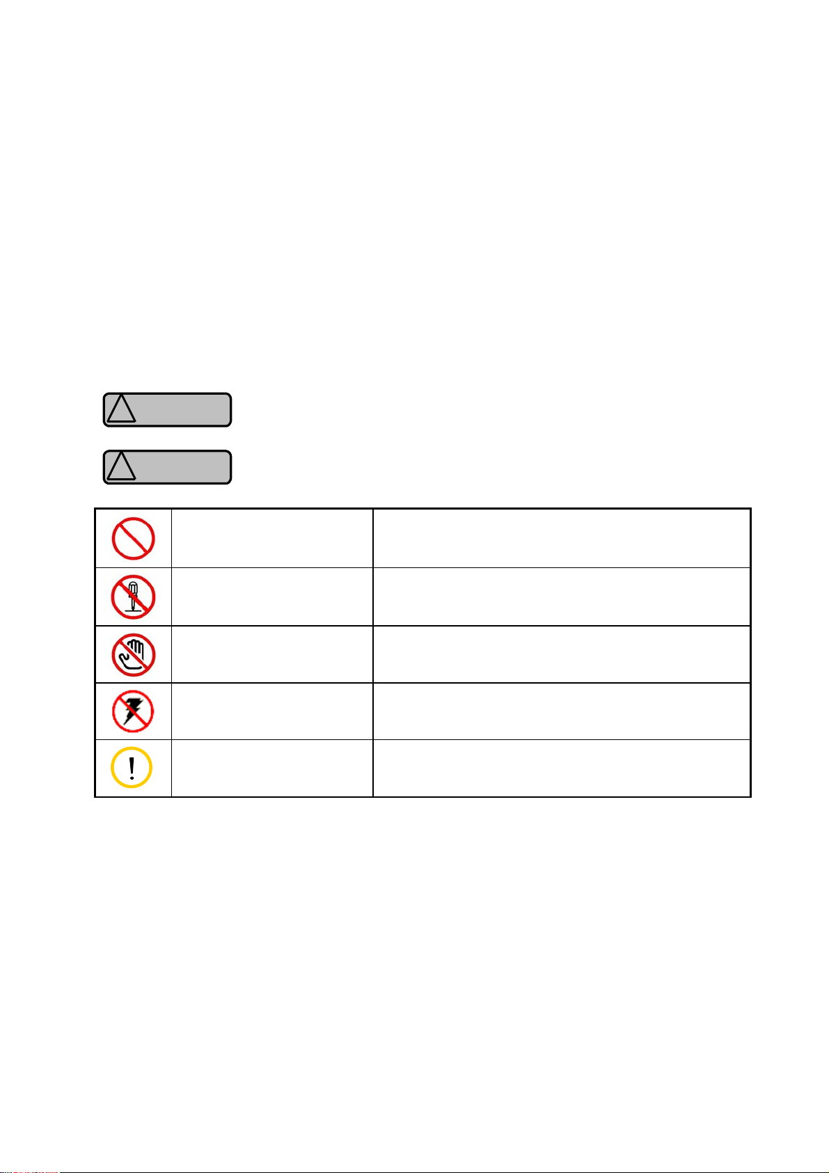
Conventions Used in This Manual
Warning
!
Caution
!
Prohibited Action
This mark means that there is a possibility of death or serious injury if you ignore or
do not follow the said instructions.
This mark means that there is a possibility of injury or physical harm if you ignore
or do not follow the said instructions.
USER’S MANUAL even if you have often purchased this
Stated action must be avoided.
USER’S MANUAL without prior
Don’t Disassemble
Equipment must not be disassembled.
Don’t Handle with Hands
Keep away from Static
Electricity
Note
Oth
er product and company names are trademarks, registered trademarks, or servicemarks of their
respective owners.
All rights reserved. No part of this publication may be reproduced or altered in any form or by any means
without the written permission of Interface Corporation.
Equipment must not be touched with hands.
Be careful of static electricity for the product damage.
Denotes a note.
© 2009 Interface Corporation
Page 3

PEX-400111
Document Description
Interface Corporation provides the following documents for this product. Please read carefully
before using it.
Manual Price Description
User’s Manual Free of charge The user’s manual including setup and hardware
specifications describes the basic operation to install this
product.
- Interface module installation
- Device driver software installation
- Product summary
- Features
- External interface specifications
- Example connection of external equipment
Technical Data Book Free of charge The technical data book is for a person who designs
hardware and software.
It includes direct control methods for hardware, I/O map,
and external specifications.
Note: You may download software drivers from our Web site (www.interface.co.jp) free of charge.
We also provide software drivers on CD-ROM for a nominal fee.
- 1 -
Interface Corporation
Page 4
PEX-400111
Handle with Care
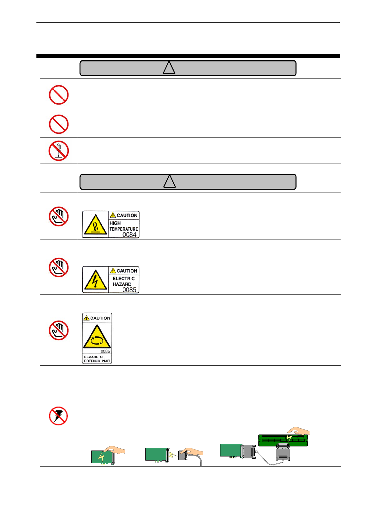
Warning
!
Please consult our Customer Support Center if you intend to use our products
for special purposes, such as the use for moving vehicles, medical treatment,
aerospace engineering, controlling nuclear power, submerged translators and
so on. Refer to “Chapter 11 Information Service,” page 44, for more details.
Keep this product away from flammable gases.
Do not modify the product. Interface Corporation assumes no liability for any
malfunctions resulting from users’ unauthorized modification of the product.
Caution
!
Do not touch around the following label because of high temperature when
using this product. Do not remove the label from the product.
Do not touch around the following label because electric shock may occur
when using high-voltage (50 Vdc or greater) for an external circuit. Do not
remove the label from the product.
Do not touch around the following label when using this product because there
is a rotary part near here. Do not remove the label from the product.
Discharge static electricity from your body by touching a grounded metal
object before handling the product. The static electricity may damage the
product.
Care should be taken in the following situations.
- When touching this product.
- When connecting a cable.
- When wiring a terminal block.
Interface Corporation
- 2 -
Page 5
PEX-400111
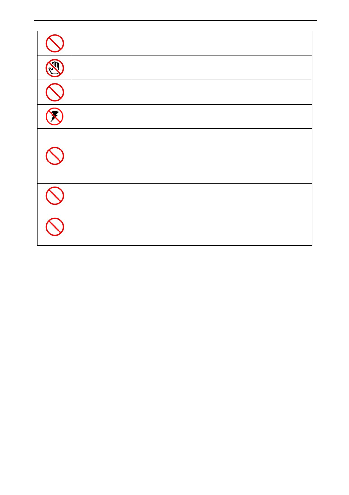
Make sure the external cable connector is disconnected before installing or
removing any interface modules. It may cause short-circuit with the interface
modules in adjacent slots.
To avoid possible injury or malfunction, do not touch the soldered surfaces
of the product.
Use this product only under the specified conditions such as power supply,
voltage, temperature, and humidity range.
Take measures to avoid and minimize shock, vibration, magnetic fields, and
static electricity in the storage or operating environment of this interface
module.
Avoid the following conditions for storage and operation.
• Extremely high temperature and humidity
• Exposure to the direct rays of the sun
• A lot of soot and dust
• Vibrations and mechanical shocks
• Chemical vapors
Keep this product away from foreign matter.
Do not forcibly bend the cable connected to each module.
This product is made under strict quality management, however, when using
this product for the purposes that may result in any damages, lost profits, or
any other incidental or consequential damages resulting from breakdown of
this product, the user is required to take adequate and appropriate measures,
such as installing safety devices to avoid possible serious accidents.
- 3 -
Interface Corporation
Page 6
PEX-400111
Environmental Sp e c ifications
Use this product only under the conditions as shown below.
Environmental Conditions
Operating temperature: 0 degrees C to 50 degrees C
Relative humidity: 20% to 90% (non-condensing)
Dust
Corrosive Gas
Noise
Typical office environment
None
Keep this product away from power source such as motors as far as possible
to avoid electromagnetic interference.
Voltage Requirements
Bus Requirements PCI Express
Interface Module Dimensions
Number of Slots Required
+3.3 Vdc (+/-0.3 V): 0.5 A (typ.)
TM
Base Specification Rev. 1.0a x1
MD1: 106.68 (D) x 64.4 (H) [mm]
1 slot
Periodic Inspections
The following inspections should be carried out on this product periodically.
Item
Checkpoint
Cable connections Be sure that all connectors and cables are installed correctly.
Card edge Check for dirt or corrosion.
Connector contacts Check for dirt or corrosion.
Interface module surfaces Surface should be free of dust and foreign matter.
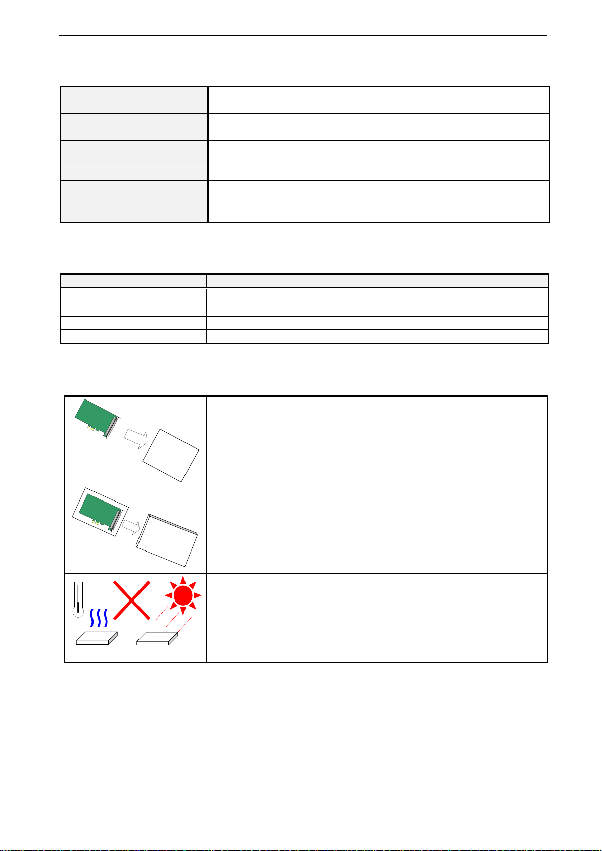
Storage
This product should be stored exactly the same way as when it was received. Proceed as follows:
electro-conductive
bag
2. Wrap this product with the original packing material.
1. Put this product back in its electro-conductive bag.
box
3. Do not expose this product to the direct rays of the sun. Avoid excessive
humidity. Store the product at room temperature.
The shape differs depending on the product.
Interface Corporation
- 4 -
Page 7

PEX-400111
Contents
Document Description 1
Handle with Care 2
Chapter 1 Summary 7
1.1 Features...................................................................................................................... 7
1.2 IEEE 1284 Compatibility.............................................................................................. 8
Chapter 2 Factory Default Settings 9
2.1 Factory Default Settings .............................................................................................. 9
Chapter 3 Setup 10
3.1 Interface Module Installation...................................................................................... 10
Chapter 4 Software Installation 11
4.1 Windows .................................................................................................................... 11
4.1.1 Installation of Device Driver Software............................................................ 12
Windows Server 2008 or Windows Vista......................................................... 12
Windows Embedded Standard, W indows XP Embedded, W indows XP, or
Windows Server 2003..................................................................................... 13
Windows 2000 ................................................................................................ 15
4.1.2 Installation of Utility Disk................................................................................ 16
4.1.3 Uninstallation of Utility Disk ........................................................................... 16
4.2 Linux ......................................................................................................................... 17
4.2.1 Serial interface.............................................................................................. 17
Installation...................................................................................................... 17
Loading a Driver Module and Making a Device Node...................................... 18
Kernel Version................................................................................................ 19
Uninstallation.................................................................................................. 19
4.2.2 Parallel Interface ........................................................................................... 20
Software Installation ....................................................................................... 20
Loading a Driver Module and Making a Device Node...................................... 21
Uninstallation.................................................................................................. 21
Chapter 5 Uninstallation 22
5.1 Interface Module Uninstallation.................................................................................. 22
- 5 -
Interface Corporation
Page 8

PEX-400111
Chapter 6 Hardware Description 23
6.1 Hardware Specifications............................................................................................ 23
6.2 Electric Characteristics.............................................................................................. 25
6.2.1 Serial interface.............................................................................................. 25
Absolute Maximum Rating (RS-232C)............................................................. 25
DC Specifications (RS-232C).......................................................................... 25
Surge Protection Voltage (RS-232C) .............................................................. 25
6.2.2 Parallel Interface ........................................................................................... 25
Absolute Maximum Rating (Parallel)............................................................... 25
DC Specifications (Parallel)............................................................................ 25
Surge Protection Voltage (Parallel)................................................................. 25
Chapter 7 Functional Description 26
7.1 Circuit Diagram.......................................................................................................... 26
7.2 Equivalent Circuits..................................................................................................... 27
7.2.1 Serial Interface Circuit (RS-232C Transceiver).............................................. 27
7.2.2 Parallel Interface Circuit ................................................................................ 27
7.3 Serial Interface Base Clock........................................................................................ 28
7.3.1 Serial Interface Transfer Rates (Bit Rate)...................................................... 28
7.3.2 Limitations on the Serial Interface Bit Rate Generator Programming.............. 29
7.4 Interrupt Sources....................................................................................................... 30
7.5 Serial Interface Half-duplex Control........................................................................... 30
7.6 AC Characteristics..................................................................................................... 31
Chapter 8 External Connections 32
8.1 External Connections................................................................................................. 32
8.2 Interface Product Pin Assignments............................................................................ 33
8.3 Signals...................................................................................................................... 34
8.4 Connection Diagrams................................................................................................ 35
8.4.1 Cabling with Terminal Block........................................................................... 35
8.4.2 Cabling with Branch Cable............................................................................. 35
8.4.3 Example Connections for Serial Interface...................................................... 36
Straight Cabling.............................................................................................. 36
Cross Cabling................................................................................................. 37
8.4.4 Example Connections for Parallel Interface ................................................... 38
25-Pin D-sub Connector (1284-A)................................................................... 38
36-Pin Centronics Connector (1284-B)............................................................ 39
36-Pin Half-Pitch Connector (1284-C)............................................................. 40
Chapter 9 Front Panel Installation 41
9.1 How to Exchange ...................................................................................................... 41
Chapter 10 Optional Products 43
10.1 Accessories............................................................................................................. 43
Chapter 11 Information Service 44
11.1 How to Get Information ............................................................................................ 44
Interface Corporation
- 6 -
Page 9

PEX-400111
Chapter 1 Summary
The PEX-400111 is a serial and parallel communications product for PCI Express-based computers. The
serial communications channel of this product is EIA RS-232C (EIA-574) compatible and can be used
as a Windows standard COM port. This product incorporates our original communications controller
which provides one 1024-byte transmit FIFO and one 1024-byte receive FIFO, and helps achieve
reliable transmission without data loss. The transfer rate is software selectable. Seven base clock
frequencies and a bit rate generator allow you to choose freely appropriate transfer rates for your
specific requirements. The parallel communications channel of this product is compatible with IEEE
1284 supporting bi-directional communications and can be used as a Windows standard parallel port.
The feature allows you to use the port as an expansion printer port and input from a peripheral device
such as a printer or image/film scanner.
1.1 Features
[Serial interface]
>>Our original communications controller
The PEX-400111 incorporates our original communications controller. The following functions are
extended.
- Transmit/receive FIFO size
- Maximum transfer rate
- Configurable transfer rate
- Automatic flow control
>>Windows standard COM port
The PEX-400111 includes a Windows standard COM port driver. This product can be used as an
expansion serial port on Windows-based computers.
>>Configurable transfer rate
A transfer rate is software selectable. This feature allows you to select an appropriate transfer rate. The
maximum transfer rate is 1 Mbps. An actual transfer rate depends on your computer, software, and
connection device.
>>1024-byte FIFOs
The communications controller provides one 1024-byte transmit FIFO and one 1024-byte receive FIFO,
and helps achieve reliable transmission without data loss.
- 7 -
Interface Corporation
Page 10
PEX-400111
>>Automatic flow control
The PEX-400111 supports automatic flow control by the serial communications controller. This feature
substantially reduces the burden on the host computer. The following list shows corresponding flow
controls on this product.
- Hardware flow control (RS/CS flow control)
- Software flow control (Xon/Xoff flow control)
>>Half-duplex transmission
The PEX-400111 can transmit data synchronizing with RS signal.
[Parallel interface]
>>IEEE 1284 mode selection
The PEX-400111 supports five modes; Byte, Compatibility, ECP, EPP, and Nibble. The ECP mode does
not support simultaneous operation of this product and a standard printer port. Some of the modes may be
unavailable due to your operating system even if a connected device supports several modes.
>>ECP data FIFO
The PEX-400111 uses the 16-byte deep FIFO in the ECP mode. This feature allows high-speed data to
transfer.
>>Windows standard parallel port
The PEX-400111 includes a Windows standard parallel port driver. This product can be used as an
expansion parallel port on Windows-based computers.
1.2 IEEE 1284 Compatibility
Model OS Compatibility Nibble Byte EPP ECP
PC/AT Compatible Windows 2000 and later Supported Supported Supported Supported Supported
Interface Corporation
- 8 -
Page 11
PEX-400111
Chapter 2 Factory Default Settings
2.1 Factory Default Settings
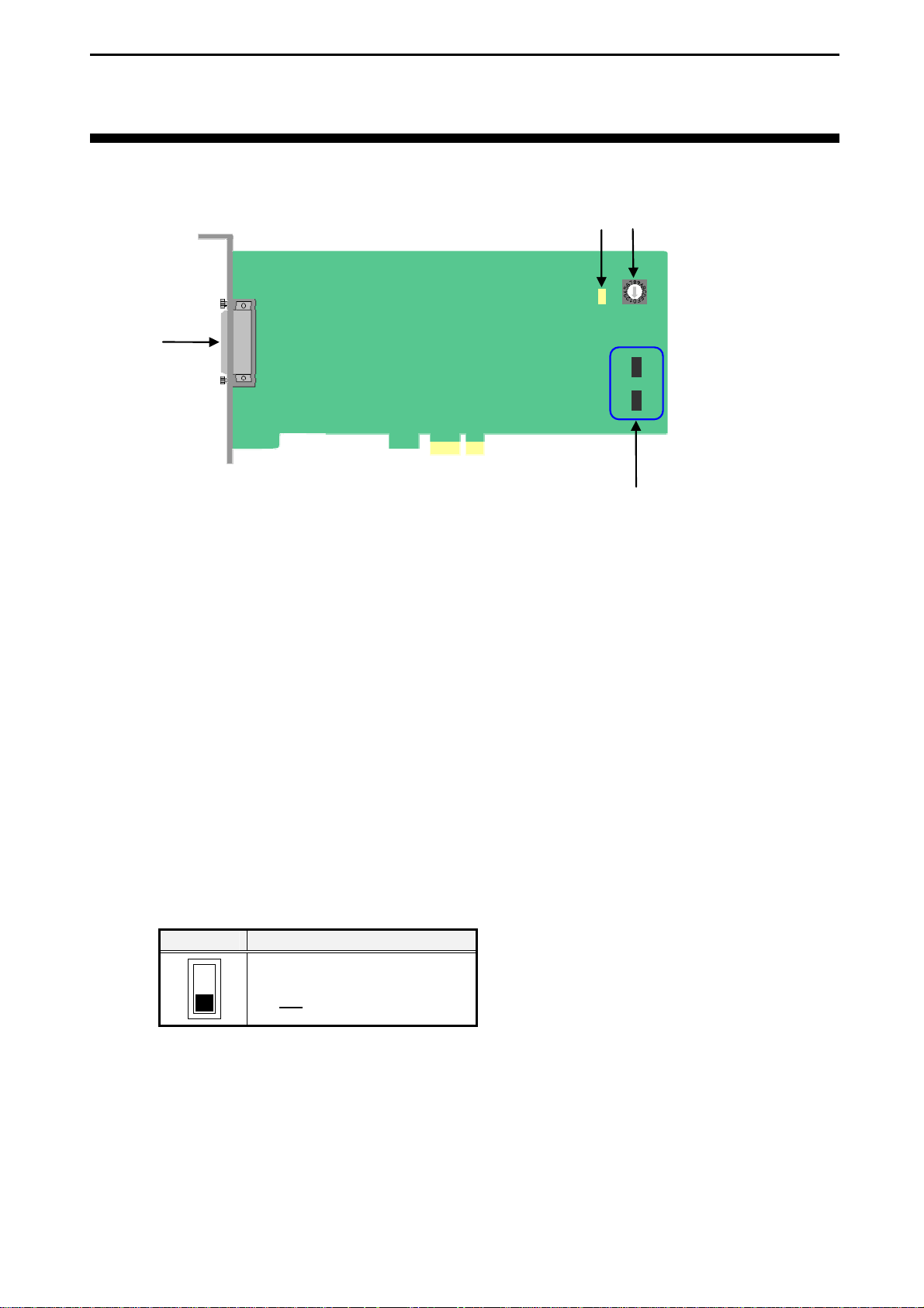
CN1
(1)
(2)
LED1
(3)
RSW1
ISP0
ISP1
(4)
B A
B A
(1) 68-pin 0.8 mm-pitch female connector (CN1)
This connector connects to external equipment.
(2) Access LED (LED1)
The LED1 glows green to indicate the CPU accesses to this product. A single access lights the LED1
for 500 ms. When continual accesses cease, the LED1 turns off 500 ms later.
(3) Interface module ID rotary switch (RSW1)
The rotary switch on each of our inteface modules identifies each interface module in cases where
our multiple interface modules of the same type are installed in the same system. Remember to set
this switch to a unique setting on each interface module so there is not a conflict among products of
the same type. When using an interface module of the same type, set the rotary switch to “0.”
(Factory default setting: 0)
(4) Reserved switch (ISP0, ISP1)
Setting Description
B
A
It must be fixed to position A.
Do not
change the setting.
The shows the switch setting position.
- 9 -
Interface Corporation
Page 12
PEX-400111
Chapter 3 Setup
This chapter explains about preparations for using this product.
<Flow>
Interface module installation
↓
Driver installation
↓
How to setup software
The interface module installation is completed. We recommend you to check the operation. Refer to
“4.1.3 Uninstallation of Utility Disk,” page 16, and “Chapter 5 Uninstallation,” page 22, for
uninstallation.
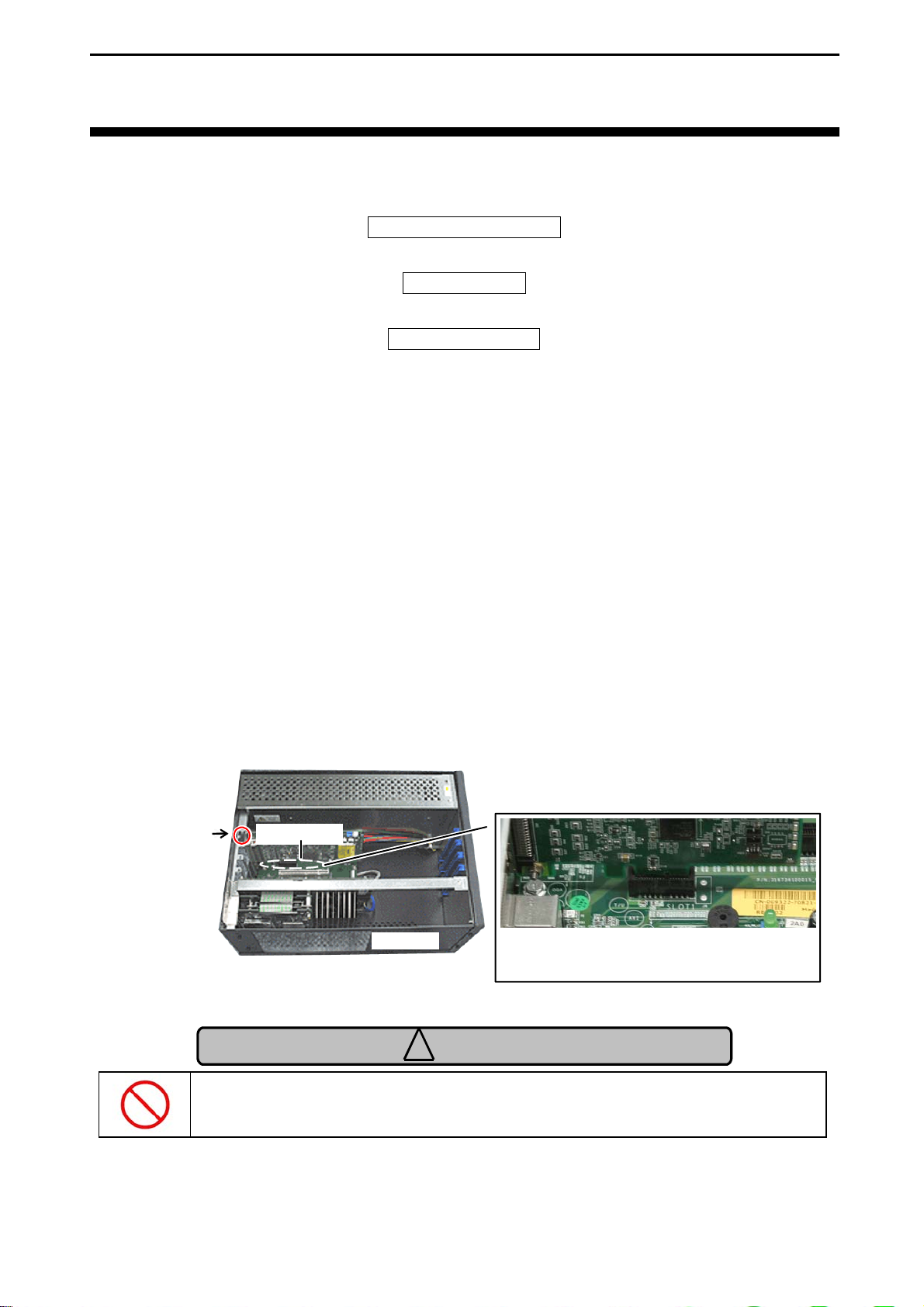
3.1 Interface Module Installation
Note: The following pictures are for reference purpose only.
1. Make sure that the system is turned off, and unplug the power cord.
2. Remove the PC case cover and a slot cover.
3. Insert the interface module into an open slot.
PCI Express connector
Screw fastening
Interface module
Computer
Insert the interface module into an open slot in
your computer.
Make sure that the goldfingers are properly inserted into the
PCI Express connector.
Caution
!
Be careful of the insert direction to avoid system damage when you insert
this product into your system.
4. Fasten the panel to the bracket with a screw.
5. Replace the cover, plug in the power cord, and turn on the computer.
Interface Corporation
- 10 -
Page 13
PEX-400111
Chapter 4 Software Installation
Information
To operate this product, the driver software is required. To download the
driver software free of charge, please visit our Web site (www.interface.co.jp
and get a user ID.
Refer to Help in the software about how to use the DLL functions, sample
programs, and utilities.
4.1 Windows
The Interface device driver software is composed as follows.
• Driver disk
This disk contains the device drivers.
Downloading procedure
>> Download the Driver Disk of GPF-4150 for your operating system from our Web site.
>> Execute the downloaded program, and then a folder is created.
Note: Please refer to “4.1.1 Installation of Device Driver Software,” page 12, for more details.
)
• Utility disk
This disk contains the Readme, Help, sample programs, utility, and so on.
Downloading procedure
>> Download the Utility Disk of GPF-4150 from our Web site.
>> Execute the downloaded program, and then [SETUP] folder is created.
>> Run the SETUP.EXE file on the [SETUP] folder. The programs will be installed to the drive
you specify.
- 11 -
Interface Corporation
Page 14

PEX-400111
4.1.1 Installation of Device Driver Software Windows Server 2008 or Windows Vista
The driver may only be installed by a member of the System Administrators group.
1. When you log on to Windows Server 2008 or Windows Vista, the device driver wizard will start
automatically. If you are prompted for an administrator password or confirmation, select Continue.
2. The Found New Hardware dialog box will appear, select Locate and install driver so ft ware
(recommended).
3. Select Don’t search online.
4. Click I don’t have the disc. Show me other options.
5. Click Browse my computer for driver software (advanced) .
6. Click Browse and specify the Win2000 driver folder downloaded from our Web site, and then click
Next.
7. Installation will start automatically.
8. Follow further instructions on your screen.
9. Repeat the installation of device driver software one more time.
Note: For Windows Server 2008 Server Core, install the driver with the following command.
<Example>
[Win2000] driver folder is in C drive: pnputil -i -a c:\Win2000\xxxx.INF
Interface Corporation
- 12 -
Page 15

PEX-400111
Windows Embedded Standard, Windows XP Embedded, Windows XP, or
Windows Server 2003
The driver may only be installed by a member of the System Administrators group.
1. When you log on to Windows Embedded Standard, Windows XP Embedded, Windows XP, or
Windows Server 2003, the device driver wizard will start automatically.
2. The Found New Hardware Wizard dialog box will appear, select Install fro m a lis t or spec i fic
location [Advanced], and then click Next.
3. Select Search for the best driver in these locations, and select Inclu de this lo cation in the
search: Then click Next.
4. Click Browse and specify the Win2000 driver folder downloaded from our Web site, and then click
Next.
5. Installation will start automatically.
6. Follow further instructions on your screen.
7. Repeat the installation of device driver software one more time.
If “parport.sys” is not found, insert the CD-ROM for your operating system and specify your
CD-ROM drive to copy.
To verify you have successfully installed the software, follow the instructions described below.
- Restart your computer.
- Click the Hardware tab in the Syste m Properties dialog box, and click Device Manager.
The list of devices installed in your computer will appear: Interface PEX-400111 [CN1](Serial
Port)[RSWxx](COMxx) and Interface PEX-400111 [CN2](Printer Port)[RSWxx](LPTxx) in the
Ports (COM & LPT), and Interface PEX-400111 in the Multifunction adapters.
The LPT port added by the PEX-400111 will be configured as a port without interrupt. To perform at
high-speed with interrupt, configure a port, follow the instructions described below.
- Open Device Manager.
- Click Ports (COM & LP T ).
- Open the Properties of Interface PEX-400111 [CN2](Printer Por t)[RSWxx](LPTxx).
- Click Port Settings tab and select a method in Filter Resource Method.
Make sure that there are no conflicts in setting up the computer resources, such as I/O addresses and
interrupt request levels. After the installation of device driver software is completed, please install the
utility disk.
- 13 -
Interface Corporation
Page 16

PEX-400111
• When importing the hardware information file for Windows Embedded Standard or
Windows XP Embedded
>> How to download the driver
1. Download the Driver Disk of GPF-4150 for its operating system from our Web site.
2. Execute the downloaded program, and then [Win2000] folder is created.
>> How to install the driver
1. Start up the Component Database Manager of Windows Embedded Standard or
Windows XP Embedded development enviroment.
2. Import our hardware information file. Follow further instructions on your screen to import the
file whose extension is SLD in the [Win2000] folder.
Interface Corporation
- 14 -
Page 17

PEX-400111
Windows 2000
The driver may only be installed by a member of the System Administrators group.
1. When you log on to Windows 2000, the device driver wizard will start automatically.
2. In the Found New Hardware Wizard dialog box, click Next.
3. Select Search for a suitable driver for my device [recommended], and then click Next.
4. Select Specify a location check box, and then click Next.
5. Click Browse and specify the Win2000 driver folder downloaded from our Web site, and then click
OK.
6. To install the driver Windows found, click Next.
7. Follow further instructions on your screen.
8. Repeat the installation of device driver software one more time.
If “parport.sys” is not found, insert the CD-ROM for your operating system and specify your
CD-ROM drive to copy.
To verify you have successfully installed the software, follow the instructions described below.
- Restart your computer.
- Click the Hardware tab in the Syste m Properties dialog box, and click Device Manager.
The list of devices installed in your computer will appear: Interface PEX-400111 [CN1](Serial
Port)[RSWxx](COMxx) and Interface PEX-400111 [CN2](Printer Port)[RSWxx](LPTxx) in the
Ports (COM & LPT), and Interface PEX-400111 in the Multifunction adapters.
The LPT port added by the PEX-400111 will be configured as a port without interrupt. To perform at
high-speed with interrupt, configure a port, follow the instructions described below.
- Open Device Manager.
- Click Ports (COM & LP T ).
- Open the Properties of Interface PEX-400111 [CN2](Printer Por t)[RSWxx](LPTxx).
- Click Port Settings tab and select a method in Filter Resource Method.
Make sure that there are no conflicts in setting up the computer resources, such as I/O addresses and
interrupt request levels. After the installation of device driver software is completed, please install the
utility disk.
- 15 -
Interface Corporation
Page 18

PEX-400111
4.1.2 Installation of Utility Disk
1. Decompress* the compression file downloaded from our Web site and run the SETUP.EXE file on
the decompression folder. The README, Help, and sample programs will be installed to the drive
you specify.
2. Follow further instructions on your screen.
3. To verify that you have successfully installed the software package, check that GPF-4150
is registered in the Interface folder of the Pr og ram Fi l es folder.
*
Decompress procedure
A. Create a directory with an appropriate name in a hard disk.
B. Copy each downloaded file to the directory created in Procedure A.
C. Run each file copied in Procedure B to decompress the file. Then a folder and file will be
created.
4.1.3 Uninstallation of Utility Disk
• Windows Server 2008 or Windows Vista
1. Click the Start button and Control Panel.
2. Click the Programs, Programs and Features, and then Uninstal l or Change a program.
3. Click Interface GPF-4150 in the list, and then click Uninstall.
4. Follow further instructions on your screen.
• Windows Embedded Standard, Windows XP Embedded, Windows XP, or Windows Server 2003
1. Click the Start button, point to Settings, and then click Control Panel.
2. Double-click Add/Remove Programs, and then click the Change or Remove Programs tab.
3. Click Interface GPF-4150 in the list, and then click Change/Remove.
4. Follow further instructions on your screen.
• Windows 2000
1. Click the Start button, point to Settings, and then click Control Panel.
2. Double-click Add/Remove Programs, and then click the Install/Uninstall tab.
3. Click Interface GPF-4150 in the list, and then click Add/Remove.
4. Follow further instructions on your screen.
Interface Corporation
- 16 -
Page 19

PEX-400111
4.2 Linux
The Interface device driver software is composed as follows.
• Driver disk
This disk contains the necessary files to run the software.
Downloading procedure
>> Download the Driver Disk [Linux/RTLinux] of GPH-4141 and GPH-8208 from our Web site.
>> If you use the CPU of SH, download the Driver Disk [SHLinux/SH-RTLinux] of GPH-4141
and GPH-8208 from our Web site.
>> The file you downloaded from our Web site is an archive file. You need to decompress the
downloaded file before using it. Please install the file whose time stamp is the latest.
4.2.1 Serial interface Installation
1. Login to your Linux system as a super user.
%su
Password:-------------Password of root
2. Change the current directory to where you downloaded the file and then decompress the file.
#cd /tmp
#tar xvzf gph4141_<architecture name>*1_(version)*2.tgz
3. The command will extract the following files in the directory.
>> lgph4141.<architecture name
>> rgph4141.<architecture name
*1
>.tgz Driver software archive for Linux
*1
>.tgz Driver software archive for RTLinux
>> common.tgz Common module archive
>> readme.txt Latest information file
>> install Shell script for installation
>> product.txt Additional file for installation
>> sh4.txt Additional file for installation
4. Run the installer.
#sh install
5. Follow further instructions displayed on your screen.
*3
Notes:
*1
•
*2
•
*3
•
Write “i386” or “sh4” depending on the architecture of your computer.
Write the latest version.
Not included in platforms of IBM PC/AT compatible.
- 17 -
Interface Corporation
Page 20

PEX-400111
Loading a Driver Module and Making a Device Node
1. Login to your Linux system as a super user.
%su
Password:-------------Passward of root
Load a Real-Time module for RTLinux.
#rtlinux start
2. Load the driver modules for kernel.
>>Linux
#modprobe cp4141
>>RTLinux
#modprobe rcp4141
3. Confirm that the communications port is recognized by using the /proc file system.
>>Linux
#cat /proc/tty/driver/cp4141
>>RTLinux
#cat /proc/tty/driver/rcp4141
Note: Refer to the Help about how to use the /proc file system.
Interface Corporation
- 18 -
Page 21

PEX-400111
Kernel Version
You may need to recompile the driver module if you upgrade to a new kernel version or change a kernel
version. Refer to the following instructions.
<dpg0100>
#cd /usr/src/interface/common/dpg0100/src
#make
#make install
<dpg0101>
#cd /usr/src/interface/common/dpg0101/src
#make
#make install
<dpg0102> for RTLinux
#cd /usr/src/interface/common/dpg0102/src
#make
#make install
Go to the src directory of Linux drivers. Then compile and install the modules.
#cd /usr/src/interface/gph4141/<architecture name>*1/
(OS name)*2/drivers/src
#make
#make install
Notes:
*1
•
Write “i386” or “sh4” depending on the architecture of your computer.
*2
•
Write “linux” for Linux and “rtl” for RTLinux.
Uninstallation
1. To remove the modules, run the shell script.
2. Run uninstall located in the gph4141/<architecture name>
Example: Assume that the installation directory is the default.
#cd /usr/src/interface/gph4141/<architecture name>*
#sh uninstall
3. Follow further instructions displayed on your screen.
*
Note:
Write “i386” or “sh4” depending on the architecture of your computer.
*
directory under the installation directory.
- 19 -
Interface Corporation
Page 22

PEX-400111
4.2.2 Parallel Interface Software Installation
1. Login to your Linux system as a super user.
%su
Password:-------------Password of root
2. Change the current directory to where you downloaded the file and then decompress the file.
#cd /tmp
#tar xvzf gph8208_<architecture name>*1_(version)*2.tgz
3. The command will extract the following files in the directory.
>> lgph8208.<architecture name
>> rgph8208.<architecture name
*1
>.tgz Driver software archive for Linux
*1
>.tgz Driver software archive for RTLinux
>> common.tgz Common module archive
>> readme.txt Latest information file
>> install Shell script for installation
>> product.txt Additional file for installation
>> sh4.txt Additional file for installation
4. Run the installer.
#sh install
5. Follow further instructions displayed on your screen.
Notes:
*1
•
Write “i386” or “sh4” depending on the architecture of your computer.
*2
•
Write the latest version.
*3
•
Not included in platforms of IBM PC/AT compatible.
*3
Interface Corporation
- 20 -
Page 23

PEX-400111
Loading a Driver Module and Making a Device Node
>>Linux
By adding a configuration of our printer port to the driver source code for standard printer port, the
port will be an alternative standard printer port. GPH-8208 does not include any driver modules for
Linux.
>>RTLinux
1. Login to your Linux system as a super user using the “su” command.
%su
Password:-------------Passward of root
2. Load a Real-Time module for RTLinux.
#rtlinux start
3. Load a driver module, common module, and interruput sharing module. Run the shell script to load
a driver module.
Example: Assume that the installation directory is the default.
#cd /usr/src/interface/gph8208/<architecture name>
#sh insrtlpara.sh
4. Create the program to control the device.
5. Run the shell script for loading cancellation to cancel the loading of RTLinux driver module.
Example: Assume that the installation directory is the default.
#cd /usr/src/interface/gph8208/<architecture name>
#sh rmrtlpara.sh
*
Note:
Write “i386” or “sh4” depending on the architecture of your computer.
*l/
rtl/drivers
*l/
rtl/drivers
Uninstallation
1. To remove the modules, run the shell script.
2. Run uninstall located in the gph8208/<architecture name>
Example: Assume that the installation directory is the default.
#cd /usr/src/interface/gph8208/<architecture name>*
#sh uninstall
3. Follow further instructions displayed on your screen.
*
Note:
Write “i386” or “sh4” depending on the architecture of your computer.
*
directory under the installation directory.
- 21 -
Interface Corporation
Page 24

PEX-400111
Chapter 5 Uninstallation
5.1 Interface Module Uninstallation
1. Make sure that your computer is turned off, and unplug the power cord from the AC outlet.
Remove the PC case cover.
2. Remove the screw from the interface module.
3. Remove the interface module from the slot gently.
Interface Corporation
- 22 -
Page 25
PEX-400111
Chapter 6 Hardware Description
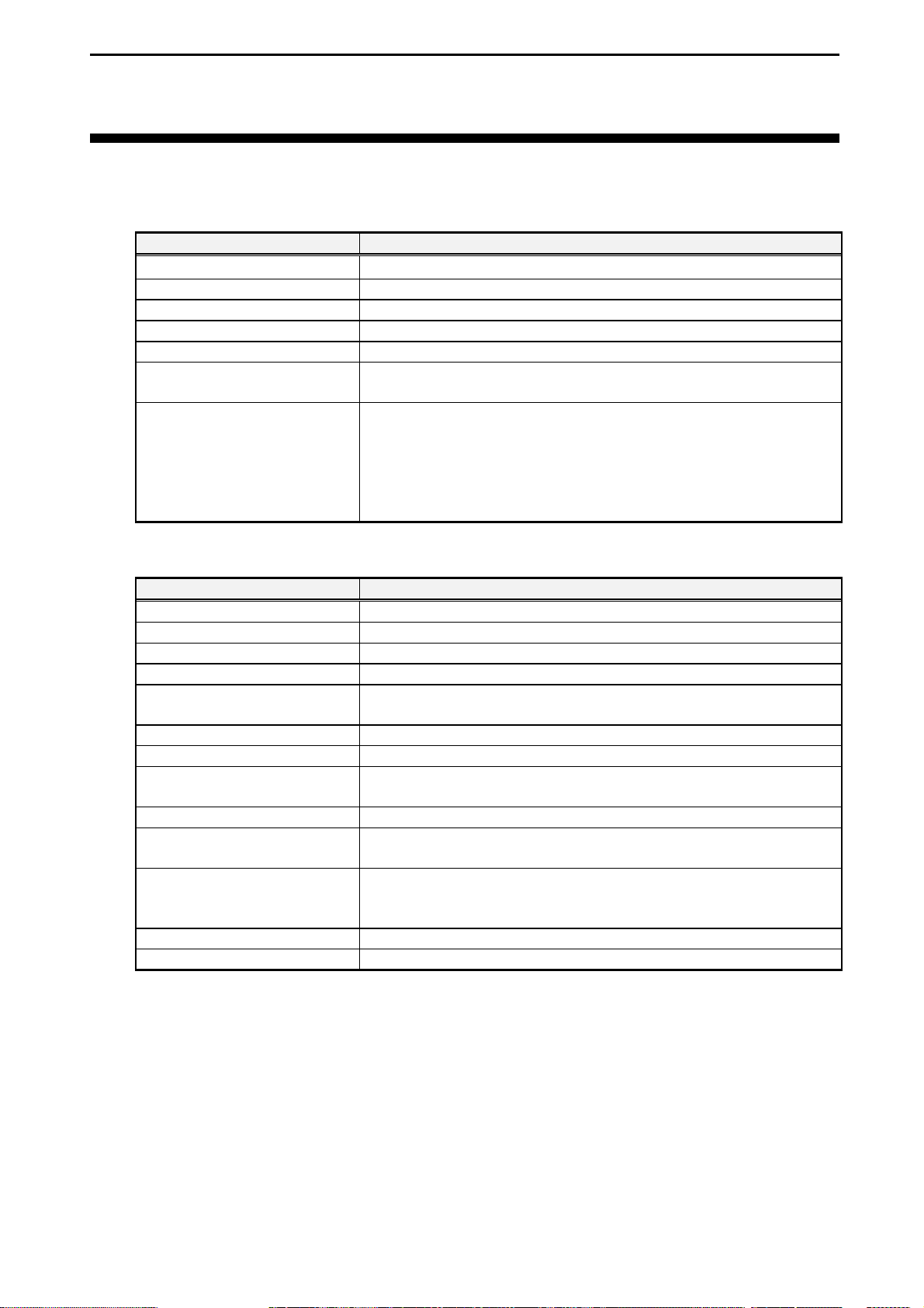
6.1 Hardware Specifications
Basic Specifications
Parameter Specification
Bus requirements PCI Express TM Base Specification Rev. 1.0a x1
Number of slots required 1 slot
Interface module dimensions MD1: 106.68 (D) x 64.4 (H) [mm]
Weight 50 g
Power consumption +3.3 Vdc (+/-0.3 V): 0.5 A (typ.)
Environmental conditions Operating temperature: 0 degrees C to 50 degrees C
Relative humidity: 20% to 90% (non-condensing)
Connectors CN1: 68-pin 0.8 mm-pitch female connector
On-board connector:
HDRA-E68LFD1T-SL (Honda Tsushin Kogyo Co., Ltd.) or
equivalent
Acceptable cable connector:
HDRA-E68MA1 (Honda Tsushin Kogyo Co., Ltd.) or equivalent
Serial Interface
Parameter Specification
Number of channels 1 channel
Communications standards RS-232C (EIA-574) compliant
Isolation No-isolation
Control signals CD, CI, CS, DR, ER, RD, RS, SD
Base clock frequencies 8.192 MHz, 12.288 MHz, 14.7456 MHz, 19.6608 MHz, 32 MHz,
49.152 MHz, and 58.9824 MHz
Transfer rates* Configurable within 8 bps to 1 Mbps
Communications mode Asynchronous communications
Serial communications
controller
RS-232C transceiver MAX3245E (Maxim Integrated Products, Inc.) or equivalent
Transmit/receive buffer
memory
Interrupt sources Receive data ready, transmit data ready, receive data time-out,
Maximum transmission length 15 m
Memory size 8 KB + 64 bytes + 16 bytes
Note: * Refer to “7.3 Serial Interface Base Clock,” page 28, for more details.
Our original communications controller
Transmit: 1024-byte FIFO for channel
Receive: 1024-byte FIFO for channel
receive data trigger, transmit data trigger, transmit idle, line status
(overrun, parity, framing, or break), modem status, flow control
- 23 -
Interface Corporation
Page 26
PEX-400111
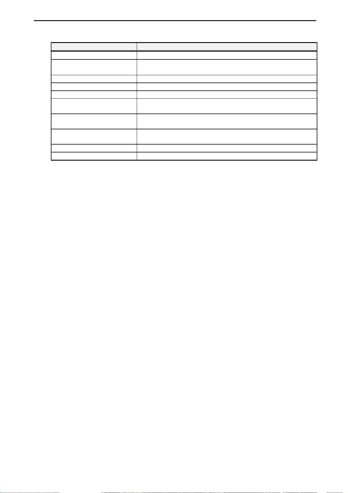
Parallel Interface
Parameter Specification
Number of channels 1 channel
Signal standard
Communications standards IEEE 1284 standard (Centronics compatible)
Windows standard parallel port Standard parallel ports supported
Isolation No-isolation
Parallel communications
controller
IEEE 1284 transceiver 74LVX161284 (Fairchild Semiconductor Incorporated) or
Communications modes Byte, Compatibility, ECP, EPP, Nibble (depending on your
Interrupt sources ACK signal, ERROR signal (in the ECP mode)
Number of I/O ports 8 ports x 2 + 4 ports
TTL level (+5 Vdc) (with 1.2 kΩ pull-up resistors, overvoltage and
reverse bias protection diodes, and noise filter)
ST78C36 (Exar Corporation) or equivalent
equivalent
operating system)
Interface Corporation
- 24 -
Page 27
PEX-400111
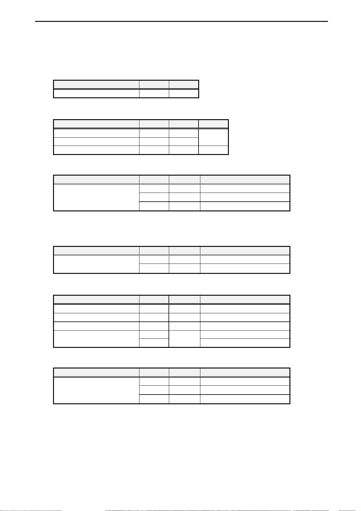
6.2 Electric Characteristics
6.2.1 Serial interface Absolute Maximum Rating (RS-232C)
Item Min. Max.
Input voltage -25 V +25 V
DC Specifications (RS-232C)
Item Min. Typ. Max.
Output voltage (3 kΩ load)
Input threshold voltage (low) +0.6 V +1.2 V
Input threshold voltage (high)
Surge Protection Voltage (RS-232C)
Item Min. Max. Condition
Surge protection voltage
+/-5 V +/-5.4 V
⎯
-15 kV +15 kV Human body model
-8 kV +8 kV Contact discharge
-15 kV +15 kV Air gap discharge
+1.5 V
⎯
+2.4 V
6.2.2 Parallel Interface Absolute Maximum Rating (Parallel)
Item Min. Max. Condition
-2.0 V +7.0 V 40 ns transient Input voltage
-0.5 V +5.5 V
DC Specifications (Parallel)
Item Min. Max. Condition
Output voltage (low)
Output voltage (high)
Input threshold voltage (low)
⎯
+2.23 V
⎯
+2.0 V D0 to D7 Input threshold voltage (high)
+2.3 V
Surge Protection Voltage (Parallel)
Item Min. Max. Condition
Surge protection voltage
-10 kV +10 kV Human body model
-6 kV +6 kV Air gap discharge
-2 kV +2 kV Machine model
+0.77 V
⎯
0.8 V
⎯
⎯
IOL = 14 mA
I
= -14 mA
OH
⎯
SELECT, nACK, nERROR, PE
- 25 -
Interface Corporation
Page 28
PEX-400111
r
r
Chapter 7 Functional Description
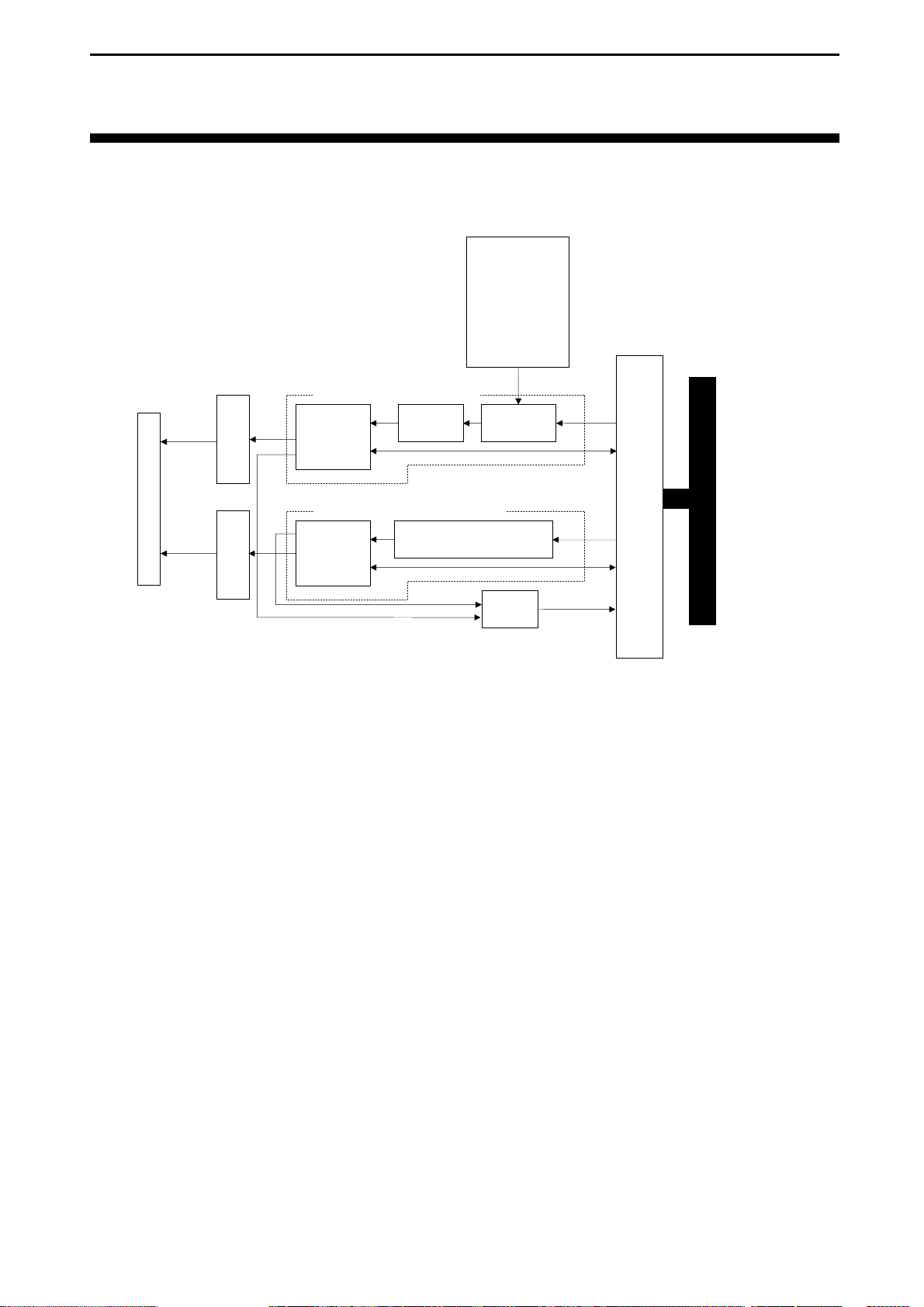
7.1 Circuit Diagram
Base clock
8.192 MHz,
12.288 MHz,
14.7456 MHz,
19.6608 MHz,
32 MHz,
49.152 MHz,
58.9824 MHz
PCI Express
RS-232C
transceive
CN1
transceive
IEEE 1284
Communications
controller
Bit rate
generator
Parallel interface control circuit
Parallel
communications
controller
ST78C36CJ44
Parallel communications controller
control circuit
Base clock
selec tion
Interrupt
circuit
PCI Express bridge circuit
Serial interface control circuit
Interface Corporation
- 26 -
Page 29
PEX-400111
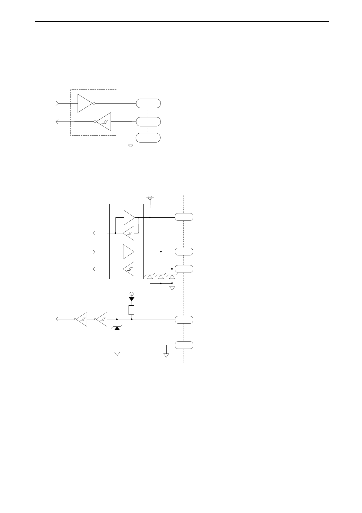
7.2 Equivalent Circuits
7.2.1 Serial Interface Circuit (RS-232C Transceiv er)
MAX3245E or equivalent
SD, ER, RS
RD, DR, CS, CI, CD
GND
Built-in surge absorber
7.2.2 Parallel Interface Circuit
IEEE1284 transceiver
74LVX161284 or equivalent
74VHC14
or equiva lent
VCC_cab
R
1.2 kΩ
Surge absorber
D0 to D7
nSTROBE, nAUTOFDX, nINIT, nSELECTIN
nACK, PE, nSELECT, nERROR
Surge absorber
74F1071 (Fairchild Semiconductor Incorporated) or equivalent
BUSY
GND
- 27 -
Interface Corporation
Page 30
PEX-400111
7.3 Serial Interface Base Clock
The PEX-400111 supports the following base clock frequencies used for the serial communications
controller:
8.192 MHz, 12.288 MHz, 14.7456 MHz, 19.6608 MHz, 32 MHz, 49.152 MHz, and 58.9824 MHz.
The maximum transfer rate of the PEX-400111 is 1 Mbps with the base clock frequency of 32 MHz.
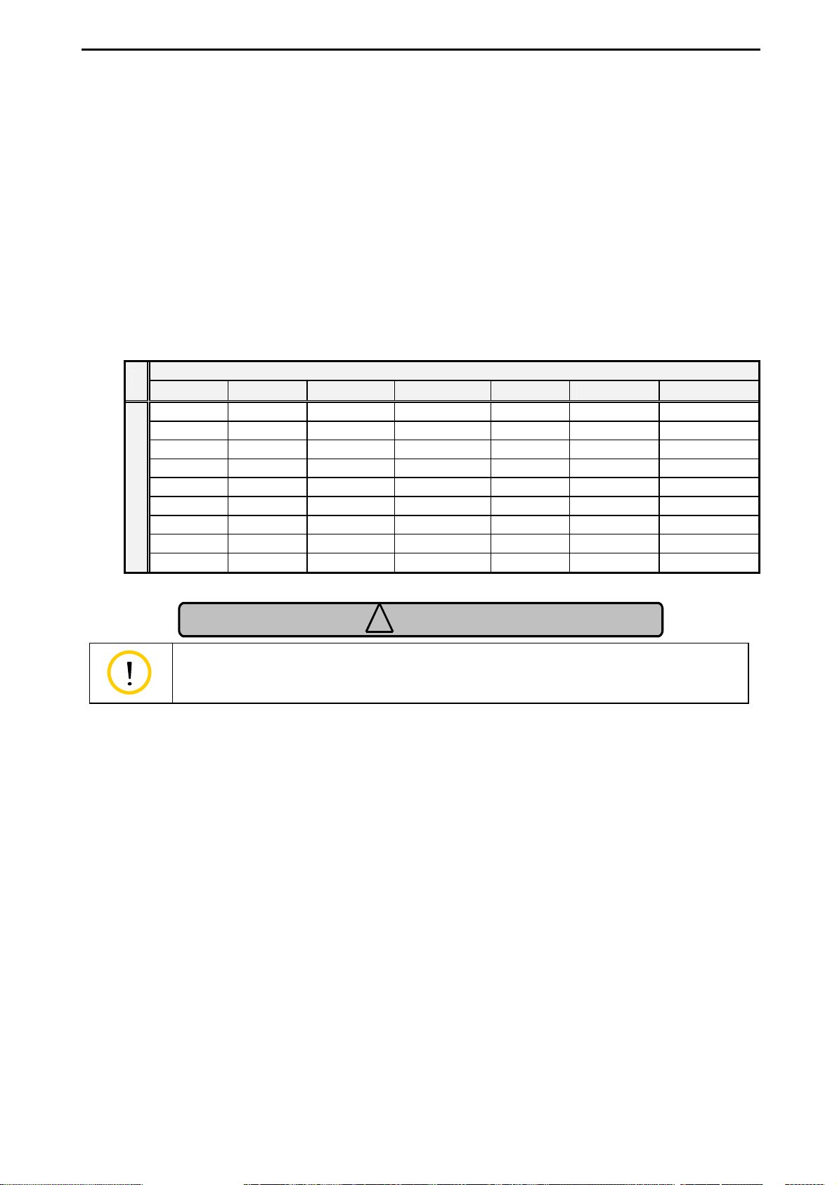
7.3.1 Serial Interface Transfer Rates (Bit Rat e)
The following table shows typical programmable transfer rates.
Refer to “7.3.2 Limitations on the Serial Interface Bit Rate Generator Programming,” page 29, for
more details. The PEX-400111 supports only asynchronous communications.
8.192 MHz 12.288 MHz 14.7456 MHz 19.6608 MHz 32 MHz 49.152 MHz 58.9824 MHz
512000 768000 921600 819200 1000000 768000 921600
256000 384000 115200 204800 500000 384000 115200
128000 192000 57600 102400 125000 192000 38400
64000 48000 9600 51200 50000 38400 14400
32000 24000 7200 10240 10000 19200 4800
4000 3000 2400 2560 2500 3000 2400
1000 1500 1200 1280 1250 1500 1800
Transfer Rates [bps]
500 75 150 600 625 750 300
8 12 15 20 32 48 64
Base Clock Frequency
Caution
!
An actual transfer rate depends on your computer, softw are, and
connection device.
Interface Corporation
- 28 -
Page 31

PEX-400111
7.3.2 Limitations on the Serial Interface Bit Rate Generator Programming
The PEX-400111 supports seven base clock frequencies (8.192 MHz, 12.288 MHz, 14.7456 MHz,
19.6608 MHz, 32 MHz, 49.152 MHz, and 58.9824 MHz) to generate the transmit/receive clock. This
feature allows you to use various transfer rates. The device driver selects a proper clock at the
initialization. Sixteen times of a selected transfer rate is required for the input clock. When a transfer rate
is 9600 bps, the input clock requires 153600 Hz and is produced by dividing the base clock frequency.
Where BaseClk is a base clock frequency (Hz) and BitRate is a transfer rate (bps), Divisor is a divisor
obtained by the following equation:
Divisor =
Select one of base clock frequencies from 8192000 Hz, 12288000 Hz, 14745600 Hz, 19660800 Hz,
32000000 Hz, 49152000 Hz, and 58982400 Hz.
If the divisor results in a decimal fraction, the combination of the base clock and transfer rate is not
available.
The following three examples describe to determine correct combinations of divisors and base clock
frequencies for the given transfer rates.
For 9600 bps transfer rate:
You can find 80 of divisor and 12288000 Hz of base clock frequency as derived from the following
result.
BaseClk
(BitRate × 16)
.
12288000 / (9600 x 16) = 80
For 64000 bps transfer rate:
You can find 8 of divisor and 8192000 Hz of base clock frequency as derived from the following
result.
8192000 / (64000 x 16) = 8
For 52000 bps transfer rate:
You cannot find any correct combinations of divisors and base clock frequencies. As a result,
52000 bps of transfer rate is not available on this product.
- 29 -
Interface Corporation
Page 32
PEX-400111
7.4 Interrupt Sources
This product generates interrupts to the computer with the following sources.
• Serial interface
- Receive data ready
- Transmit data ready
- Receive data time-out
- Receive data trigger
- Transmit data trigger
- Transmit idle
- Line status (overrun, parity, framing, or break)
- Modem status
- Flow control
• Parallel interface
- ACK signal
- ERROR signal (in the ECP mode)
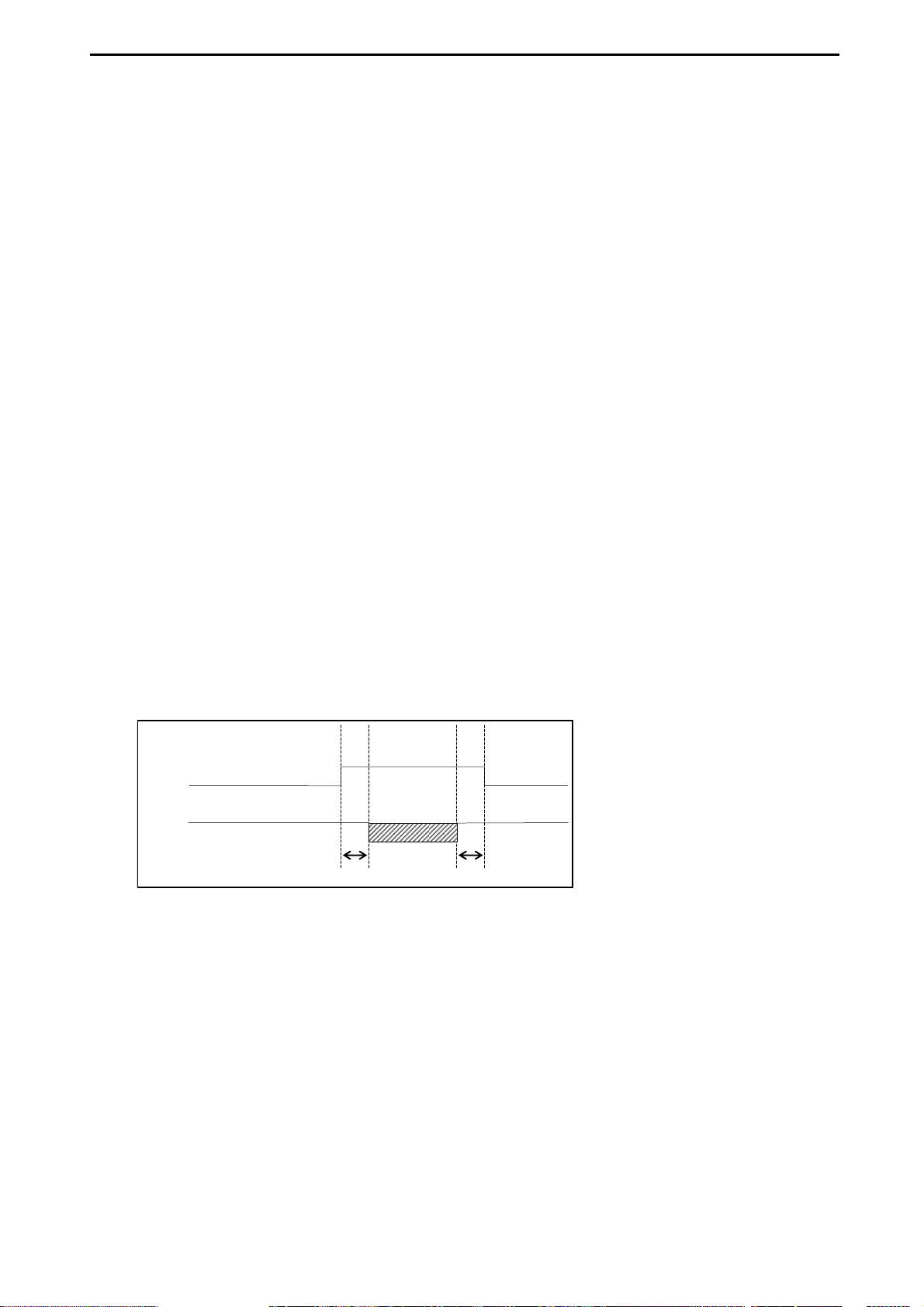
7.5 Serial Interface Half-duplex Control
The PEX-400111 supports the half-duplex transmission. This function controls signals and configures
the delay time (setup time/hold time).
ON
RS
SD
Setup time
Setup time: The delay time between the assertion of the RS signal and the start of data writing
Hold time: The delay time between the end of data transmission and the deassertion of the RS signal
Hold time
OFFOFF
Interface Corporation
- 30 -
Page 33
PEX-400111
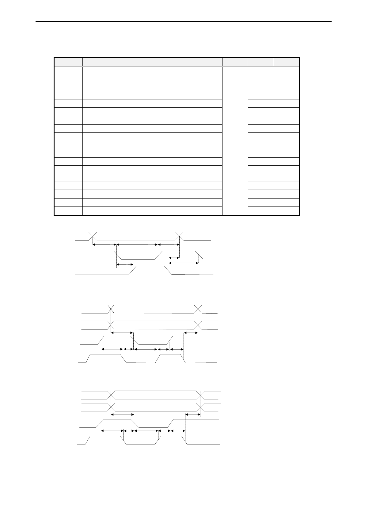
7.6 AC Characteristics
Symbol Parameter Min. Typ. Max.
T1 D0-D7 setup to nSTROBE active
T2 nSTROBE width
T3 D0-D7 hold from nSTROBE inactive 450 ns
T4 D0-D7 hold from BUSY inactive 80 ns
T5 nSTROBE active to BUSY active
T6 BUSY inactive to nSTROBE active 680 ns
T7 D0-D7, nAUTOFDX setup to nSTROBE active 0 ns 60 ns
T8 D0-D7, nAUTOFDX hold from BUSY active 80 ns 180 ns
T9 nSTROBE inactive to BUSY inactive 0 ns
T10 BUSY inactive to nSTROBE active 80 ns 200 ns
T11 nSTROBE active to BUSY active 0 ns
T12 BUSY active to nSTROBE inactive 80 ns 180 ns
T13 D0-D7, BUSY setup to nACK active
T14 D0-D7 data hold from nAUTOFDX active
T15 nACK inactive to nAUTOFDX active 80 ns 200 ns
T16 nAUTOFDX active to nACK active 0 ns
T17 nACK active to nAUTOFDX inactive 80 ns 200 ns
T18 nAUTOFDX inactive to nACK inactive
D0 to D7
nSTROBE
BUSY
T1
T5
T2
600 ns
⎯
⎯
500 ns
⎯
⎯
⎯
⎯
0 ns
⎯
⎯
0 ns
T3
T4
T6
⎯
Parallel port FIFO timing chart
D0 to D7
nAUTOFDX
nSTROBE
BUSY
T7
T9
T10 T11
T8
T9
T12
Parallel port transmit timing chart in the ECP mode
D0 to D7
BUSY
nACK
nAUT
OFDX
T13
T15
T17 T16
Parallel port receive timing chart in the ECP mode
T14
T18
T15
- 31 -
Interface Corporation
Page 34
PEX-400111
Chapter 8 External Connections
8.1 External Connections
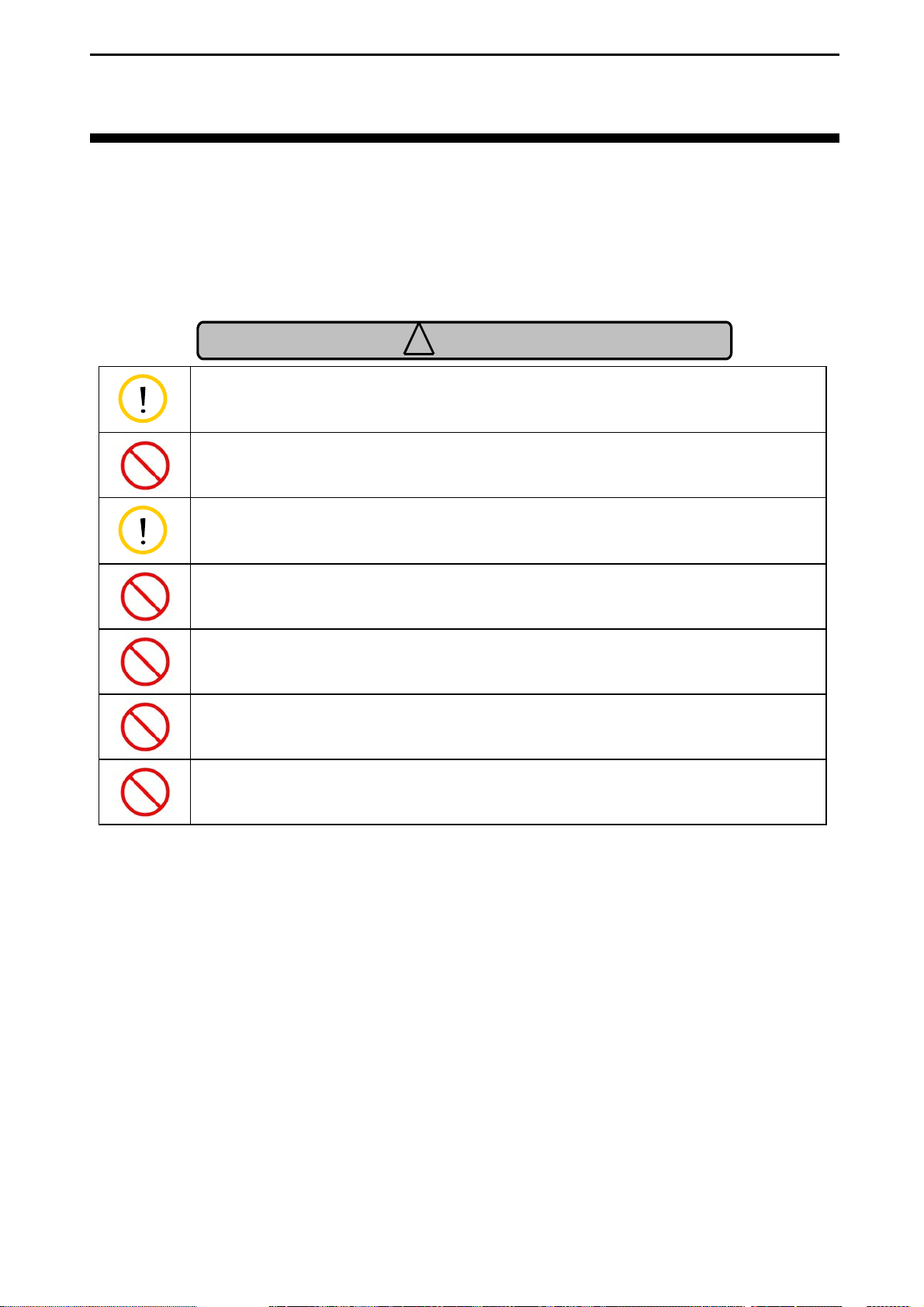
FAILURE TO OBSERVE THESE IMPORTANT SAFETY PRECAUTIONS MIGHT RESULT
IN EXCESSIVE VOLTAGE IN THE INTERFACE MODULE CIRCUITS, CAUSING AN
ELECTRICAL FIRE, WITH POSSIBLE OPEN FLAME AND SMOKE.
Caution
!
Do not open any input signals. If input signals (CD, CI, CS, and DR) are not
used for communications, connect them to ground.
Use this product only under the conditions specified in this manual. Failure to
observe these precautions may lead to malfunctions, product failure, and/or
injury.
To achieve precise data acquisition, we recommend you to use shielded or
shorter cables as much as possible to eliminate interference caused by noise.
Moreover, move noise sources away.
Never connect signals for serial interface to any signals other than the
RS-232C (EIA-574) standard.
Do not apply voltage less than or equal to -25 Vdc or greater than or equal to
+25 Vdc to signals for serial interface.
Never connect signals for parallel interface to any signals other than the TTL
level.
Do not apply voltage less than or equal to -2 Vdc or greater than or equal to
+7 Vdc to signals for parallel interface.
Interface Corporation
- 32 -
Page 35
PEX-400111
d
R
d
d
d
d
d
R
K
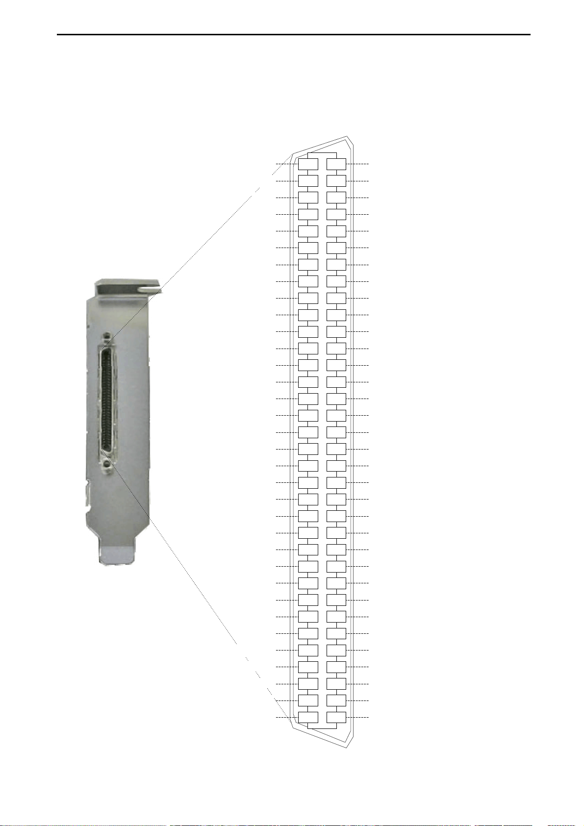
8.2 Interface Product Pin Assignments
Connector catalog number:
HDRA-E68LFD1T-SL (Honda Tsushin Kogyo Co., Ltd.) or equivalent
GND
GND
GND
CI
Reserved
CS
Reserve
RS
Reserved
D
GND
Reserve
Reserve
nSELECTIN
Reserve
Reserve
Reserve
nINIT
Reserved
nERRO
Reserved
nAUTOFDX
Reserved
SELECT
Reserved
PE
Reserved
BUSY
Reserved
nAC
Reserved
nSTROBE
GND
GND
3468
3367
3266
3165
3064
2963
2862
2761
2660
2559
2458
2357
2256
2155
2054
1953
1852
1751
1650
1549
1448
1347
1246
1145
1044
943
842
741
640
539
438
337
236
135
GND
Reserved
Reserved
ER
Reserved
SD
Reserved
RD
Reserved
Reserved
Reserved
CD
Reserved
Reserved
Reserved
Reserved
Reserved
D7
Reserved
D6
Reserved
D5
Reserved
D4
Reserved
D3
Reserved
D2
Reserved
D1
Reserved
D0
GND
GND
Reserved: Reserved pin. Do not connect to external equipment.
- 33 -
Interface Corporation
Page 36
PEX-400111
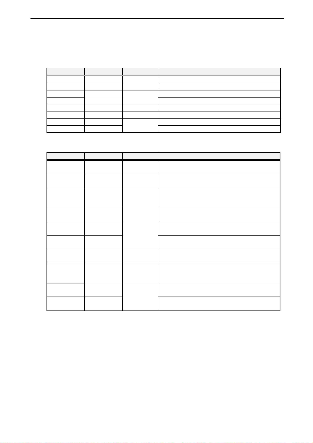
8.3 Signal s
Signal Description
Serial interface
Signal Pin Number Direction Description
CD 23 Data carrier detect
RD 27
SD 29 Transmit data
ER 31
DR 59 Input Data set ready
RS 61 Output Request to send
CS 63 Clear to send
CI 65
Parallel interface
Signal Pin Number Direction Description
nSTROBE
D0 to D7
37
3, 5, 7, 9, 11,
13, 15, 17
nACK
39
BUSY
PE
SELECT
nAUTOFDX
41
43
45
47
nERROR
49
nINIT
nSELECTIN
51
55
Input
Receive data
Output
Data terminal ready
Input
Call indicator
Output This signal shows that valid data are output (on D0
to D7). It is an active-low signal.
Input/output These signals are data bus.
Input
This signal shows that the printer receives data
correctly by negative pulses. It is an active high
signal.
This signal shows that the printer is not ready to
receive data. It is an active-high signal.
This signal shows paper-out condition. It is an
active-high signal.
This signal shows that the printer is selected. It is
an active-high signal.
Output This signal is an auto line-feed signal. It is an
active-low signal.
Input This signal shows that an error occurred. During
error condition, the printer keeps low level. It is an
Output
active-low signal.
This signal is an initialization signal. It is an
active-low signal.
This signal selects the printer. It is an active-low
signal.
Interface Corporation
- 34 -
Page 37
PEX-400111
8.4 Connection Diagrams
By using our optional products, the connection to the external circuit can be easily achieved. Refer to
“8.2 Interface Product Pin Assignments,” page 33, “8.4.3 Example Connections for Serial Interface,”
page 36, and “8.4.4 Example Connections for Parallel Interface,” page 38, before connecting this
product to the external circuit.
8.4.1 Cabling with Terminal Block
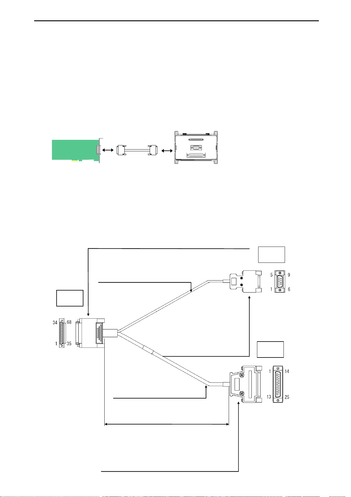
TNS-6840: 68-pin 0.8 mm-pitch connector printer terminal block
Interface module
Optional cable
8.4.2 Cabling with Branch Cable
CWB-9125RD
68-pin 0.8 mm-pitch male connector
Connector: HDRA-E68MA1 (Honda Tsushin Kogyo Co., Ltd.) or equivalent
Connector cover: HDRA-E68LGKPH (Honda Tsushin Kogyo Co., Ltd.)
Cable: UL20276 30AWG or equivalent
Cable diameter: φ 4.8 mm
CN1
Optional terminal block
9-pin D-sub male connector
Connector: 17DE-23090-C
(DDK Ltd.) or equivalent
Connector cover: 17JE-09H-1C
(DDK Ltd.) or equivalent
Stud: 17L-002C
(DDK Ltd.) or equivalent
Screw: #4-40UNC
or equivalent
CN2
CN3
Cable: UL20276 30AWG or equivalent
Cable diameter: φ 5.3 mm
25-pin D-sub female connector
Connector: 17DE-13250-C (DDK Ltd.) or equivalent
Connector cover: 17JE-25H-1C (DDK Ltd.) or equivalent
Stud: 17L-002C (DDK Ltd.) or equivalent
Screw: #4-40UNC
0.25 m
- 35 -
Interface Corporation
Page 38
PEX-400111
m
8.4.3 Example Connections for Serial Interface
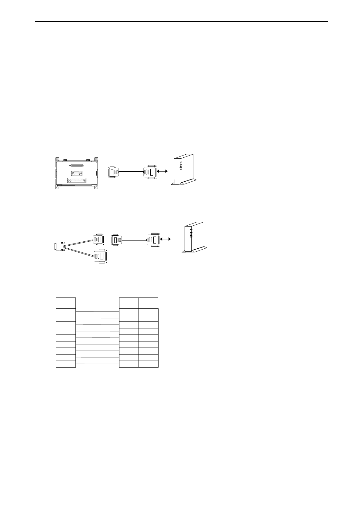
The following figures show example connections between the PEX-400111 and an external device with
our optional products. If the connecting device has its own specific instructions, you should refer to the
documentation that comes with it and follow the instructions to properly connect this product with it. By
using our optional products, the serial interface connector of the PEX-400111 will be converted to 9-pin
D-sub connector. Do not open any input signals. If input signals (CD, CI, CS, and DR) are not used for
communications, connect them to the GND signal.
Straight Cabling
Connect our optional product to a modem by using a straight cable.
Optional
terminal block
(TNS-6840)
Optional cable
(CWB-9125RD)
Signal
CD
RD
SD
ER
GND
DR
RS
CS
CI
Straight cable Modem
Straight cable
Modem (25-pin D-sub)
CI
Pin
Number
8
3
2
20
7
6
4
5
22
Signal
CD
RD
SD
ER
SG
DR
RS
CS
Mode
Interface Corporation
- 36 -
Page 39
PEX-400111
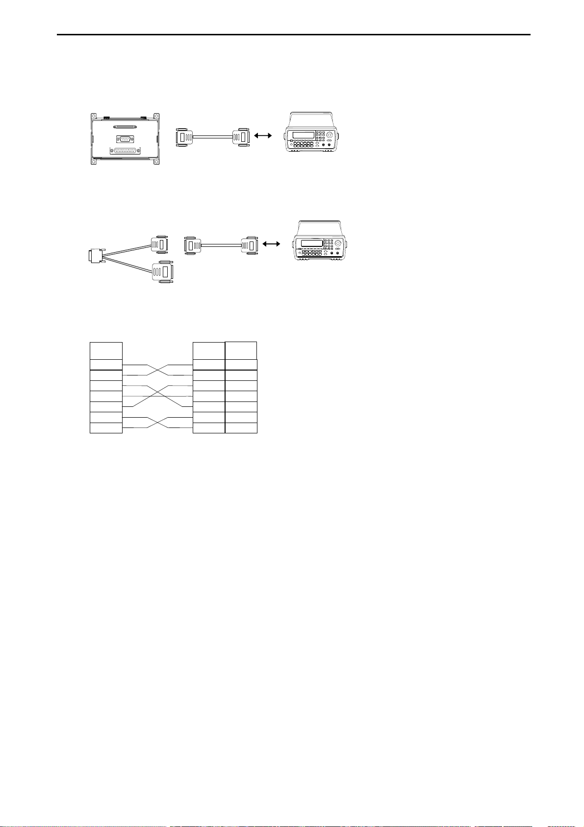
Cross Cabling
Connect our optional product to a function generator by using a cross cable.
Optional
terminal block
(TNS-6840)
Optional cable
(CWB-9125RD)
Function generator (9-pin D-sub)
Signal Signal
RD
SD
ER
GND
DR
RS
CS
Cross cable
Cross cable
Pin
Number
RD
SD
ER
SG
DR
RS
CS
Function generator
Function generator
2
3
4
5
6
7
8
- 37 -
Interface Corporation
Page 40
PEX-400111
r
r
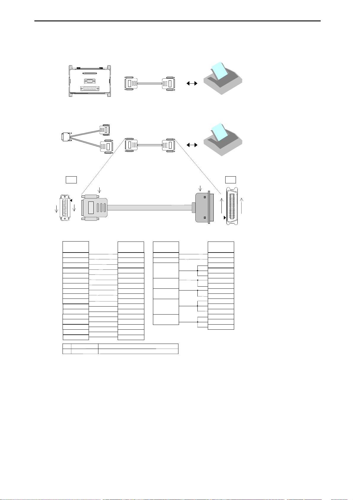
8.4.4 Example Connections for Parallel Interface
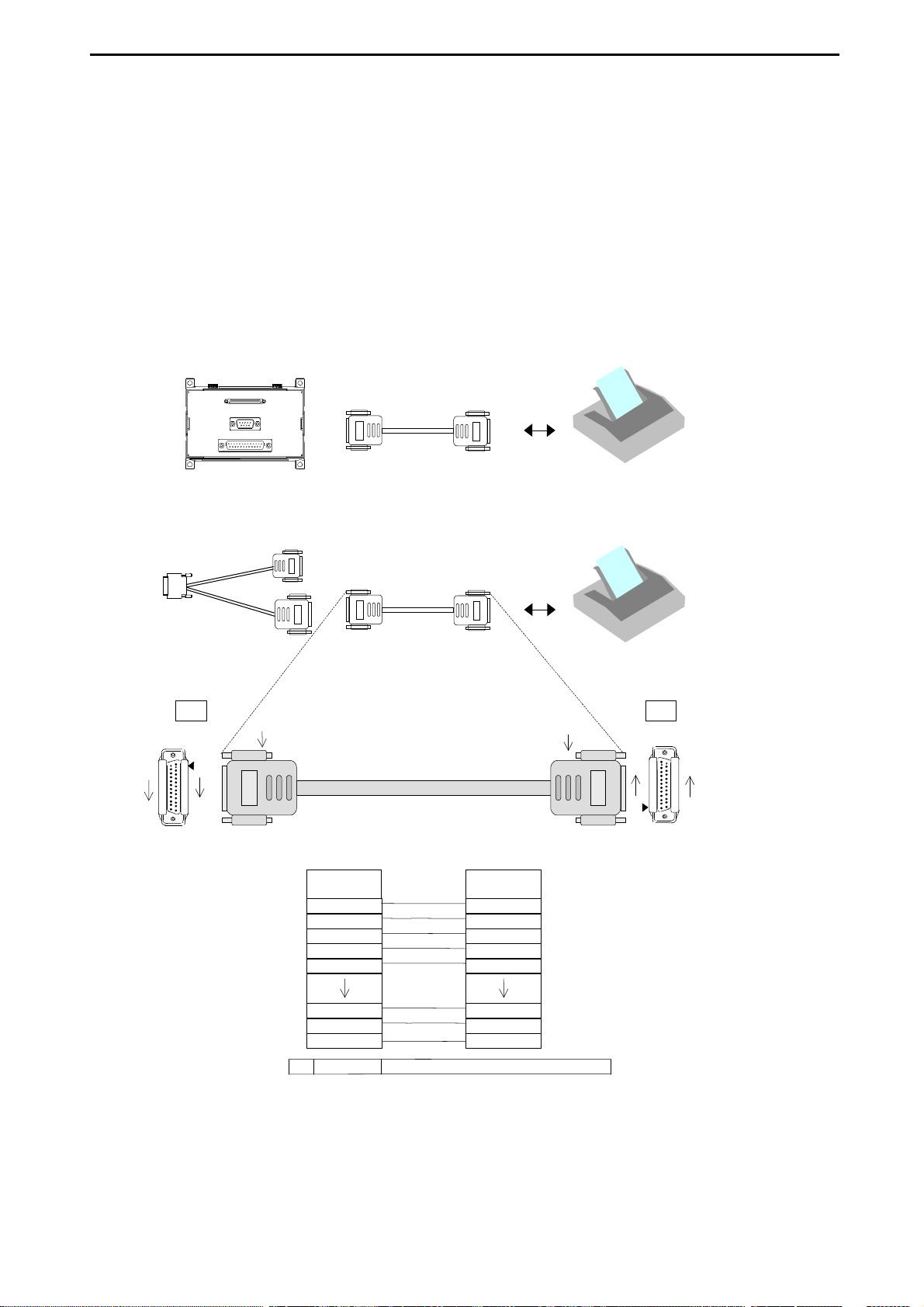
The following figures show example connections between the PEX-400111 and a device which has a
different type of connector. If the connecting device has its own specific instructions, you should refer to
the documentation that comes with it and follow the instructions to properly connect this product with it.
By using our optional products, the parallel interface connector of the PEX-400111 will be converted to
1284-A connector (25-pin D-sub connector).
25-Pin D-sub Connector (1284-A)
Connect our optional product to CN1 of the cable (IEEE 1284 A-A cable) as shown in the figure below.
Optional cable
(CWB-9125RD)
14
25
Optional
terminal block
(TNS-6840)
(1)
1
13
25-pin D-sub male connector (A)
IEEE 1284 printer cable
IEEE 1284 printer cable
CN1 connector
pin number
1
2
3
4
5
CN2 connector
pin number
1
2
3
4
5
Printe
Printe
(1)
13
1
25-pin D-sub male connector (A)
CN2CN1
25
14
23
24
25
(1)
23
24
25
Connecto r
GL-25L (Ho nda Tsushin Kogyo Co ., Ltd. ) or equivalent
Interface Corporation
- 38 -
Page 41
PEX-400111
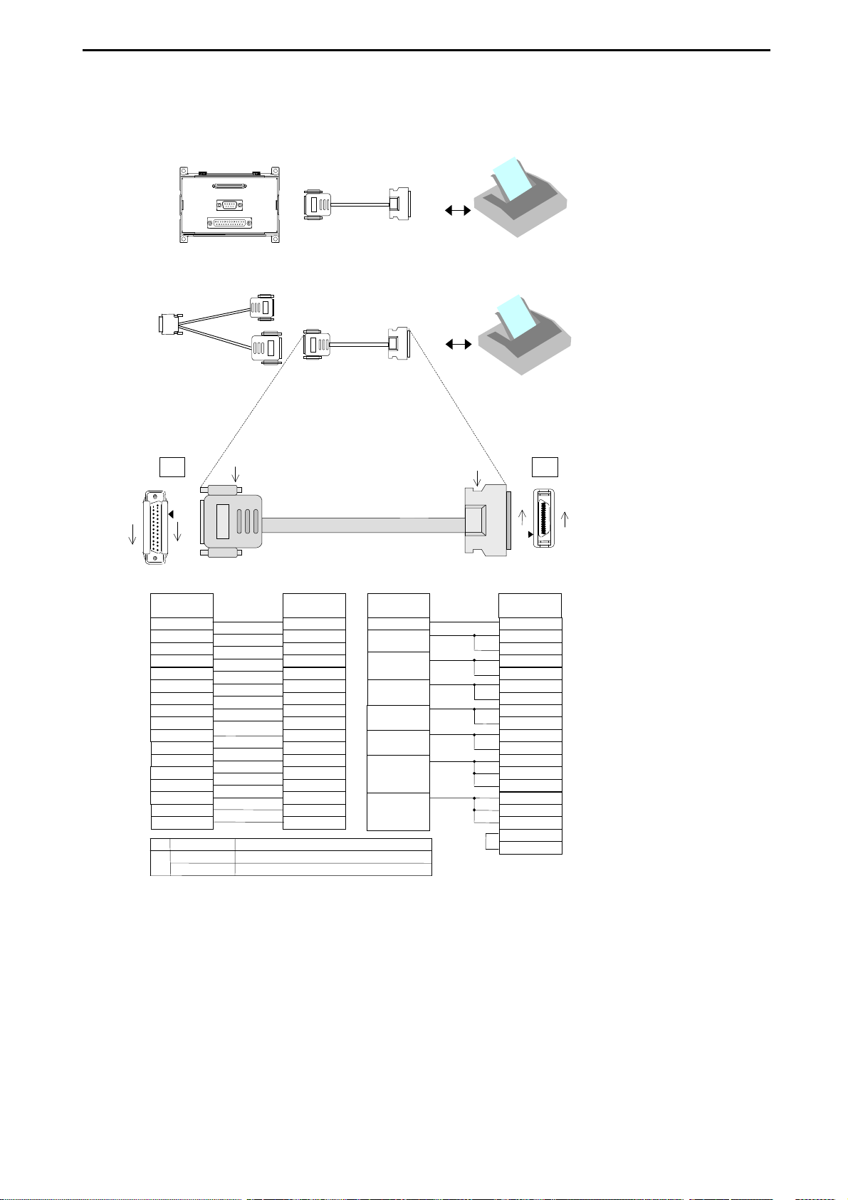
36-Pin Centronics Connector (1284-B)
Connect our optional product to CN1 of the cable (IEEE 1284 A-B cable) as shown in the figure below.
(CWB-9125RD)
14
25
CN1 connector
pin number
(1)
(2)
Optional
terminal block
(TNS-6840)
Optional cable
(1)
1
13
25 -pin D-su b male conn ect or ( A)
1
2
3
4
5
6
7
8
9
10
11
12
13
14
15
16
17
Connector
Connector
GL-25L (Honda Tsushin Kogyo Co., Ltd.) or equivalent
57-30360 (DDK Ltd. ) or equivalent
IEEE 1284 printer cable
IEEE 1284 printer cable
CN1 connector
pin number
1
2
3
4
5
6
7
8
9
10
11
12
13
14
32
31
36
CN1 connector
pin number
Printer
Printer
(2)
36-pin Centro nics male connector (B)
18
19
21
22
23
22
25
23
28
24
29
25
CN2CN1
18
1
CN2 connector
pin number
15
16
19
20
21
22
23
24
25
26
27
28
29
30
33
36
19
- 39 -
Interface Corporation
Page 42
PEX-400111
p
p
p
9
p
r
36-Pin Half-Pitch Connector (1284-C)
Connect our optional product to CN1 of the cable (IEEE 1284 A-C cable) as shown in the figure below.
Optional
IEEE 1284 printer cable
terminal block
(TNS-6840)
Optional cable
IEEE 1284 printer cable
(CWB-9125RD)
CN1 CN2
14
25
1
13
25-p in D-sub male connec tor (A)
CN1 connector
in number
1
2
3
4
5
6
7
8
9
10
11
12
13
14
15
16
17
Connector(1)
Connector
(2)
Connec tor cover
(1)
CN2 connector
in number
15
6
7
8
9
10
11
12
13
3
1
5
2
17
4
14
16
GL-25L (Honda Tsushin Kogyo Co., Ltd. ) or equivalent
10136-6000EL (Sumitomo 3M Limited) or equ ivalent
10336-A200-00 (Sumitomo 3M Limited) or equivalent
CN1 connector
in number
18
1
22
20
23
21
25
22
23
24
25
36-p in half-pit ch male con necto r (C)
(2)
Printer
Printe
18
1
CN1 connector
in number
33
24
25
26
27
28
29
30
31
19
22
20
21
23
32
34
35
18
36
36
19
Interface Corporation
- 40 -
Page 43
PEX-400111
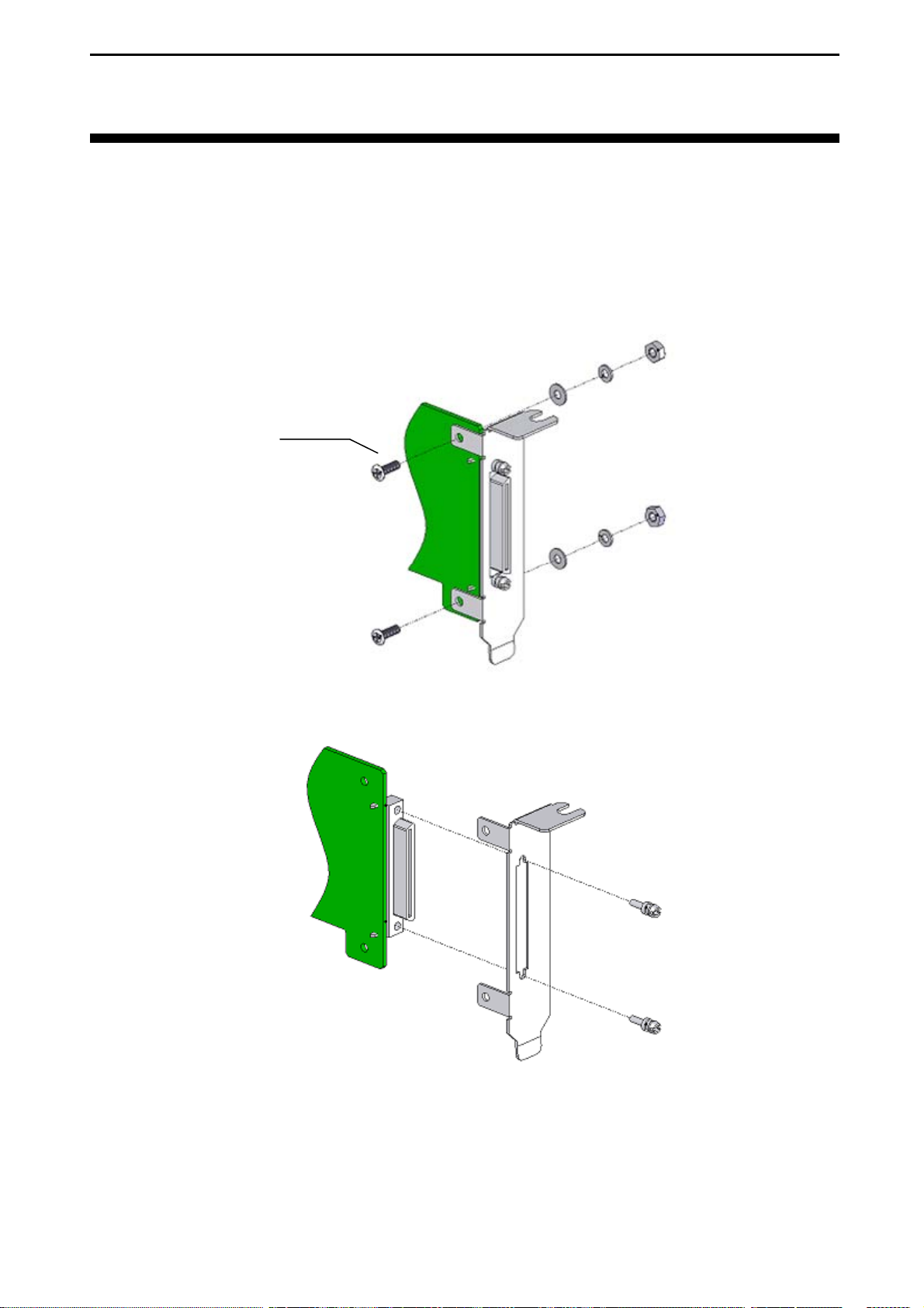
Chapter 9 Front Panel Installation
This product has a low profile front panel assembled with it. If you want to use the product in a
starndard slot, replace the low profile panel with a standard panel that cames with this product.
9.1 How to Exchange
1. Release the screws and hexagon nuts that hold the panel.
M2.5 screw
2. Release the screws that hold the connector. Then, remove the panel.
- 41 -
Interface Corporation
Page 44
PEX-400111
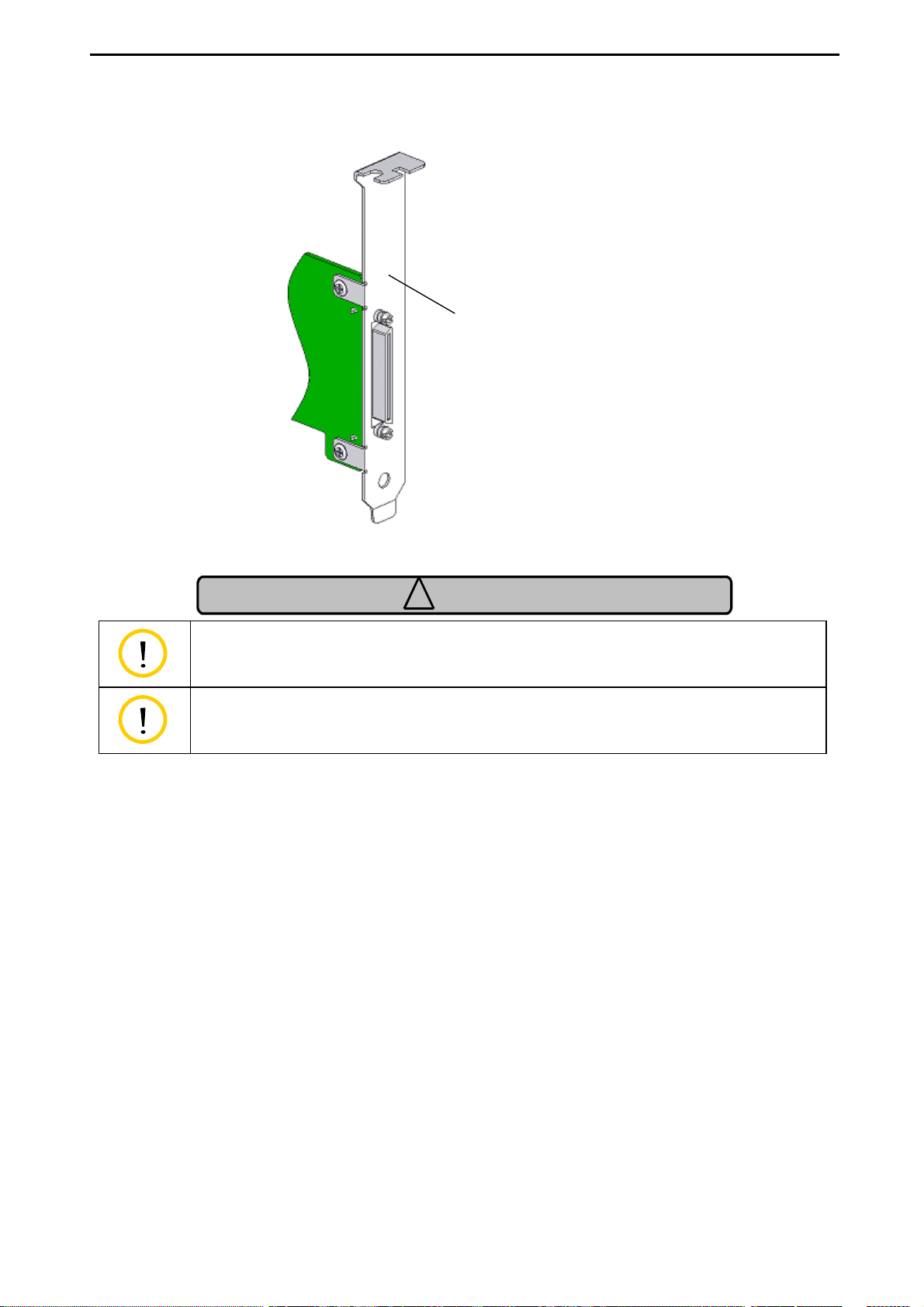
3. Assemble the standard panel to the product in the reverse procedure.
Standard panel
Caution
!
Use an appropriate driver bit not to strip the thread.
Fix the screws tightly not to loose.
Interface Corporation
- 42 -
Page 45
PEX-400111
Chapter 10 Optional Products
10.1 Accessories
Refer to our Web site (www.interface.co.jp), for more details.
Cables
Model Description
CWB-5608 68-pin 0.8 mm-Pitch Male Cable (0.8 m, 2.62 ft.)
CWB-5612 68-pin 0.8 mm-Pitch Male Cable (1.2 m, 3.93 ft.)
CWB-5615 68-pin 0.8 mm-Pitch Male Cable (1.5 m, 4.92 ft.)
CWB-9125RD
Terminal Blocks
Model Description
TNS-6840 68-Pin 0.8 mm-Pitch Connector Printer Terminal Block
Software
Model Description
GPF-4150 Win32 Asynchronous Serial Communications/Printer Port Driver Software
GPH-4141 Asynchronous Serial Communications Driver Software for Linux/RT
GPH-8208 Linux/RTLinux Driver Software for Printer Interface Module
Printer Branch Cable (Serial: 9-Pin D-Sub Connector/Parallel: 25-Pin D-Sub
Connector)
- 43 -
Interface Corporation
Page 46
PEX-400111
Chapter 11 Information Service
11.1 How to Get Information
We have a lot of valuable information on our Web site. Please visit our Web site and get your necessary
information.
Japan: www.interface.co.jp
International: www.interface-world.com
To download user’s manuals and device driver software, a registered user ID is required.
Technical Support Frequently asked questions, white papers. glossary, and so on.
Product Information What’s new, specifications, product selection guides, and so on
Useful Information Price information, rental information, distributors
Download Service Drivers, technical documents like sample programs and user’s manual data
Note: The design and contents of the Web site are under constant review. Therefore, there might be some
changes in its design and contents.
Interface Corporation
- 44 -
Page 47

PEX-400111
Revision History
Version Date Comments
1.0 November, 2009 First Release
Due to constant product improvements, the information in this USER’S MANUAL is subject to change
without prior notice.
- 45 -
Interface Corporation
Page 48

Indemnification
Interface Corporation makes no warranties regarding damages resulting from installation or use of this
product, whether hardware or software, and the user assumes all risk.
Interface Corporation shall not be liable for any incidental or consequential damages, including damages or
other costs resulting from defects which might be contained in the product, product supply delay or product
failure, even if advised of the possibility thereof. Customer’s right to recover damages caused by fault or
negligence on the part of Interface Corporation shall be limited to product improvement or exchange. Interface
Corporation does not assume the responsibility for compensation.
This product including its software may be used only in Japan. Interface Corporation cannot be responsible for
the use of this product outside Japan. Interface Corporation does not provide technical support service outside
Japan.
Interface Corporation provides only the exchange maintenance service outside Japan. The technical support
shall be limited to e-mail only.
Warranty
This product is warranted in accordance with our warranty provision. This warranty does not apply to the
software products, accessories, and expendable supplies such as batteries.
Notes:
• You can determine the warranty period at our Web site by the serial number and part number of your
product. Those without internet access should contact the Customer Support Center.
• Please refer to the insertion about repair, replace, and export of Interface products.
In principle, we do not charge for repair during the warranty period. (Customer is responsible for all shipping
charges.)
The Warranty provided herein does not cover expendable supplies such as batteries and damages, defects,
malfunctions, or failures caused by impact during transportation while under owner’s responsibility; owner’s
failure to follow the instructions and the precautions contained in this manual; modification and/or repair of
the product by other than Interface Corporation, trouble caused by use with peripherals not specified by
Interface Corporation, power failure or surges, fire, earthquake, tidal wave and/or flood, and transit damage.
This warranty is applied only when this product is used in Japan.
All repairs are accepted at your expense after the warranty period.
Rerepair is warranted only if the same components are broken within six months from the last repair.
(Rerepair is limited to repairable components.) When you request rerepair, please make sure to attach the
previous repair report. If the report is not attached, we treat the request as a new repair request.
Export
The foreign exchange and foreign trade law of Japan controls the export of this product, due to its possible use
as a STRATEGIC MATERIAL. Therefore, before you export this product, you must secure an export permit
from the government of Japan.
Page 49

Repair and maintenance
We provide repair and maintenance service for your damaged product. If you need this service, please follow
the procedures for repair and maintenance applications. You can also download a user’s manual of Japanese
version fr om our We b sit e belo w.
URL: www.interface.co.jp
For assistance
If you would like to inquire our products, please contact below.
Customer Support Center
(for Assistance)
Sales Information Center
(for Repair and Maintenance)
Phone: 0120- 447 213 ( in Ja pan)
(Available from 9:00 a.m. to 5:00 p.m. Monday to Friday except for
holiday s and c om pany holi day s)
FAX: 0120-4 5825 7 (i n Jap an)
E-mail: [email protected]
Phone: 082- 262- 163 0 (in Jap an )
(Available from 9:00 a.m. to 5:00 p.m. Monday to Friday except for
holiday s and c om pany holi day s)
Fax: 082-262- 15 52 ( in Japan )
MEU-A400111 Ver. 1.0 Vol. 1/1
 Loading...