

Page 1

Manageable Gigabit Switch
Preface
This manual describes how to install and use the Manageable
Gigabit Switch. This switch introduced here is designed to deliver
full scalability with SNMP/RMON web-based management
functions by providing:
z 24 x 10/100BaseTX fixed ports and optional 2 x
1000BaseT/SX/LX ports.
z 16 x 10/100BaseTX fixed ports and optional 1 x 8-Port
10/100BaseTX/100BaseFX module, 2 x 1000BaseT/SX/LX
ports.
For the two Gigabit ports, it allows options of fiber type and
wavelength at user’s discretion. This switch brings a simple answer
to today’s complicated networking environments.
To get the most out of this manual, you should have an
understanding of Ethernet networking concepts.
In this manual, you will find:
• Features on the switch
• Illustrative LED functions
• Installation instructions
• Management Configuration
• SNMP, DHCP, IGMP…
• Specifications
User’s Manual 1
Page 2

Manageable Gigabit Switch
Table of Contents
PREFACE 1
TABLE OF CONTENTS 2
PRODUCT OVERVIEW 5
MANAGEABLE 16/24 + 2 GIGABIT SWITCH 5
PACKAGE CONTENTS 5
PRODUCT HIGHLIGHTS 6
Basic Features 6
Management Support 6
FRONT PANEL DISPLAY 7
PHYSICAL PORTS 9
SWITCH MANAGEMENT 9
Administration console via RS-232 serial port 9
Web-based browser interface 9
External SNMP-based network management application 10
INSTALLATION 11
SELECTING A SITE FOR THE SWITCH 11
CONNECTING TO POWER 12
CONNECTING TO YOUR NETWORK 13
Cable Type & Length 13
Cabling 15
SWITCH MANAGEMENT 16
MANAGEMENT ACCESS OVERVIEW 16
ADMINISTRATION CONSOLE 17
Direct Access 17
Modem Access 18
WEB MANAGEMENT 18
SNMP-BASED NETWORK MANAGEMENT 18
PROTOCOLS 19
MANAGEMENT ARCHITECTURE 19
MENU-DRIVEN CONSOLE MANAGEMENT 20
LOGGING ON TO THE SWITCH 20
At the screen prompt 20
SWITCH MANAGEMENT SCREEN 21
Navigating Through the Console Interface 22
2 User’s Manual
Page 3

Manageable Gigabit Switch
PERFORMING BASIC MANAGEMENT ACTIVITIES 22
Start with Selection Menu 23
General Management Configurations 24
LAN Port Configurations 25
Console Port Configurations 27
PERFORMING ADVANCED MANAGEMENT ACTIVITIES 28
Start with Selection Menu 29
L2 Switching DataBase 30
IP Networking 35
Bridging 43
Static Filtering 44
MAC Address In-Filters 45
Spanning Tree Functions 46
SNMP Functions 50
Other Protocols 52
Port Mirroring 53
QoS Setup 54
Sending and Receiving Files 59
LOGOUT 61
SAVE SETTINGS 61
RESTORE DEFAULT SETTINGS 61
REBOOT 61
W
EB-BASED BROWSER MANAGEMENT 62
LOGGING ON TO THE SWITCH 62
UNDERSTANDING THE BROWSER INTERFACE 63
PERFORMING FILE ACTIVITIES 64
Start with Selection Menu 64
PERFORMING BASIC SETUP ACTIVITIES 66
Start with Selection Menu 66
LAN Port Configuration 68
Console Port Configuration 71
PERFORMING ADVANCED SETUP ACTIVITIES 73
Start with Selection Menu 73
MAC Address Management 74
IP Networking 78
Per Port Statistics 84
Bridging 84
Static MAC Filter 85
IP Multicast Group 88
VLAN Perspective 88
Spanning Tree Perspective 91
SNMP 93
Other Protocols 95
Port Mirroring 96
QoS 97
SNMP & RMON MANAGEMENT 106
OVERVIEW 106
SNMP AGENT AND MIB-2 (RFC 1213) 106
RMON MIB (RFC 1757) AND BRIDGE MIB (RFC 1493) 107
RMON Groups Supported 107
Bridge Groups Supported 108
User’s Manual 3
Page 4

Manageable Gigabit Switch
SPECIFICATIONS 109
4 User’s Manual
Page 5
Manageable Gigabit Switch
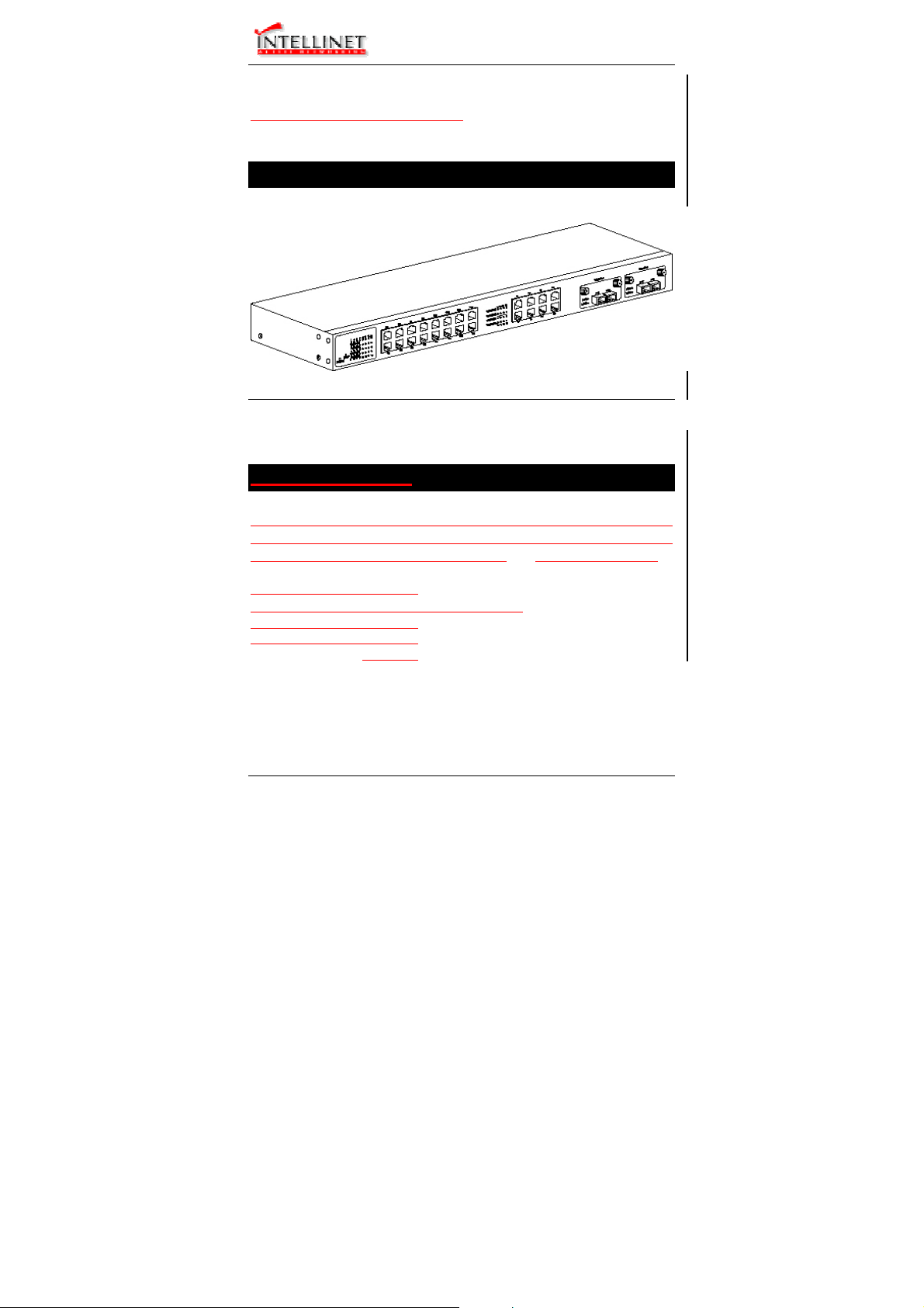
Product Overview
Manageable 16/24 + 2 Gigabit Switch
Front View
Package Contents
When you unpack the product package, you shall find the items
listed below. Please inspect the contents, and report any apparent
damage or missing items immediately to your authorized reseller.
3
User’s Manual 5
3
3
3
3
This Manageable Switch
User’s Manual
AC power cord
RS232 cable
Rackmount brackets with screws
Page 6

Manageable Gigabit Switch
Product Highlights
Basic Features
♦ 24 x 10/100BaseTX ports with RJ-45 connectors, plus
options of 2 x 1000BaseT/SX/LX ports, auto-MDIX on port
17 ~ port 24
♦ 16 x 10/100BaseTX ports with RJ-45 connectors, plus
options of 1 x 8-Port 10/100BaseTX/100BaseFX module
(auto-MDIX on TX ports of 8-Port module), 2 x
1000BaseT/SX/LX ports
♦ Auto-negotiation for speed and duplexity on all
10/100BaseTX ports
♦ Full wire-speed forwarding rate
♦ Store-and-forward mechanism
♦ Back-pressure and IEEE 802.3x compliant flow control
♦ Supports 32K MAC addresses
♦ Provides 2MBytes memory buffer
♦ Front panel reset button
♦ Front panel port status LEDs
♦ Standard 19” rackmount size, one-unit-height
Management Support
VLAN
♦ Port-based VLAN
♦ 802.1Q tagged VLAN
PORT-SECURITY
♦ Limit number of MAC addresses learned per port
♦ Static MAC addresses stay in the filtering table
PORT-MIRRORING
♦ Port-mirroring provided through dedicated ports
COS (IEEE802.1p Classification of Service)
♦ 4-level transmission priorities: 4 queues per output port
♦ Packet transmission scheduled using Weighted Round
Robin (WRR)
♦ User-defined weights
6 User’s Manual
Page 7
Manageable Gigabit Switch
♦ Classification of packet priority can be based on either a
VLAN tag on packet or a user-definable port priority
INTERNETWORKING PROTOCOLS
♦ Bridging:
802.1D Spanning Tree
802.1p/Q – GARP/GVRP
♦ Routing:
RIP
RIP-2
DHCP-Relay
ICMP Router Discovery Message
♦ IP Multicast:
IGMP Snooping
Maximum of 128 VLANs and IP multicast
sessions
♦ Bandwidth Control
NETWORK MANAGEMENT METHODS
♦ Console port access via RS-232 cable
♦ Telnet remote access
♦ SNMP agent:
MIB-2 (RFC1213)
Bridge MIB (RFC1493)
RMON MIB (RFC1757) – statistics, history, alarm and
events
VLAN MIB (802.1Q/RFC2674)
Private MIB
♦ Java applet-based MIB browser
♦ Web browser support based on HTTP server and CGI
parser
♦ Kermit/TFTP software-upgrade capability
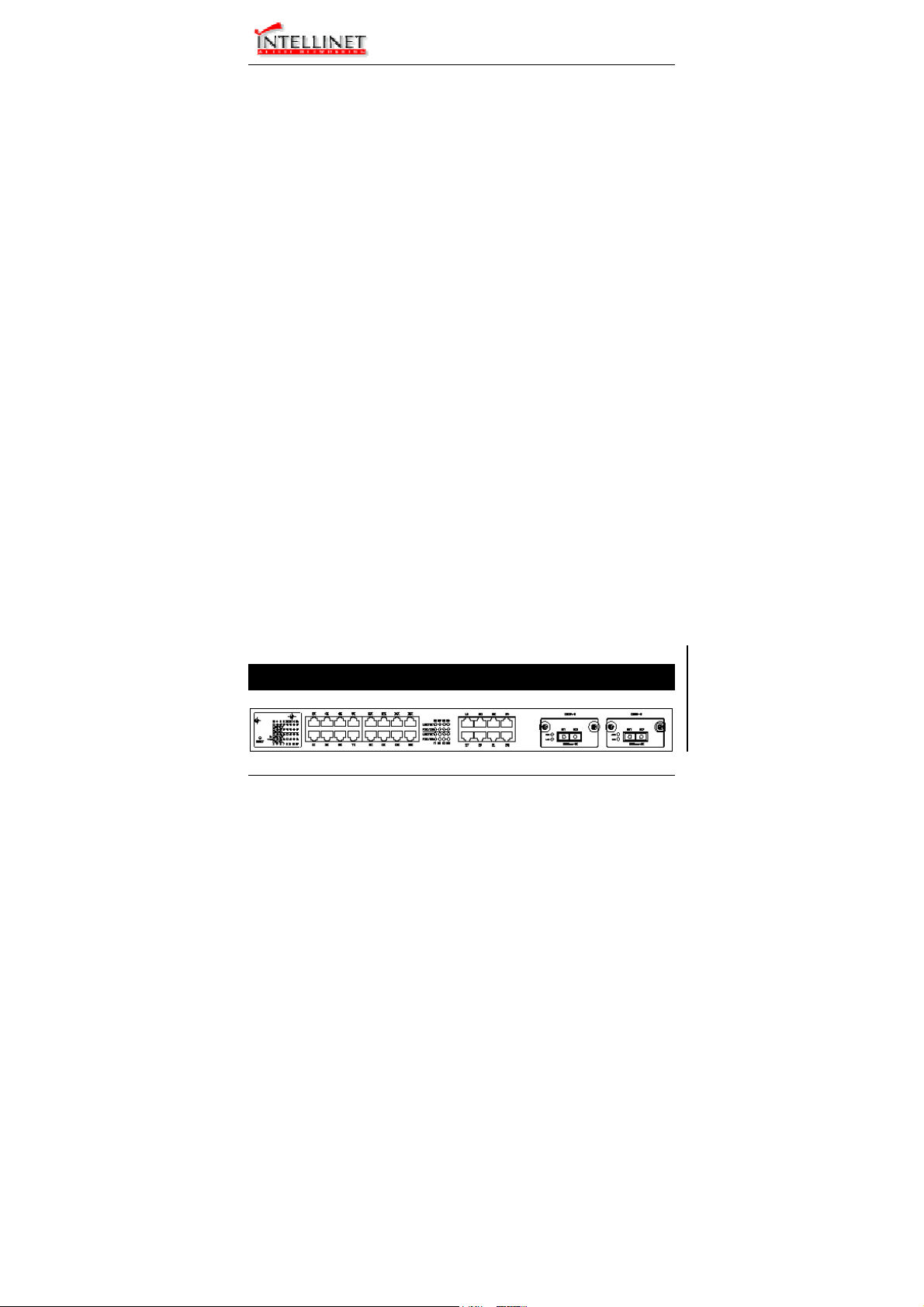
Front Panel Display
User’s Manual 7
Page 8

Manageable Gigabit Switch
c POWER
This LED comes on when the switch is properly connected to power and
turned on.
d Port Status LEDs
The LEDs are located at the left side of each section, displaying status for
each respective port. Please refer to the following table for more details.
LED State Indication
A valid network connection established.
LNK stands for LINK.
Transmitting or receiving data.
ACT stands for ACTIVITY.
Connection in full duplex mode.
FDX stands for FULL-DUPLEX.
Collision occurred.
COL stands for COLLISION.
LNK/ACT
FDX/COL
On
Flashing
On
Flashing
Off Connection in half-duplex mode.
e Gigabit Port Status LEDs
The LEDs are located at the left side of each Gigabit module, displaying
status for each respective port. Please refer to the following table for more
details.
LED State Indication
Transmitting or receiving data.
ACT stands for ACTIVITY.
No activity.
A valid network connection established.
LNK stands for LINK.
ACT
LNK
Flashing
Off
On
Off No connection.
8 User’s Manual
Page 9

Manageable Gigabit Switch
Physical Ports
The Manageable Gigabit Switch provides:
z 24 x 10/100TX fixed ports and options of 2 x 1000T/SX/LX
ports.
z 16 x 10/100TX fixed ports and options of 1 x 8-Port
10/100TX/100FX module, 2 x 1000T/SX/LX ports.
CONNECTIVITY
z
SC connectors on Gigabit ports
z ST, SC, VF-45, MT-RJ connectors on 100FX ports
z RJ-45 connectors on TX ports
MODE SELECTION
• 10BaseT full-duplex mode
• 10BaseT half-duplex mode
• 100BaseTX/FX full-duplex mode
• 100BaseTX/FX half-duplex mode
• 1000BaseT/SX/LX full-duplex mode
• Auto-negotiating mode
Switch Management
Administration console via RS-232 serial port
The switch provides an onboard serial port, which allows the switch to
be configured via a directly connected terminal or a Telnet session.
Web-based browser interface
The switch also boasts a point-and-click browser-based interface that
lets users access full switch configuration and functionality from a
Netscape or Internet Explorer browser.
User’s Manual 9
Page 10

Manageable Gigabit Switch
External SNMP-based network management application
The switch can also be configured via SNMP.
10 User’s Manual
Page 11

Manageable Gigabit Switch
Installation
This chapter gives step-by-step instructions about how to install the
switch:
Selecting a Site for the Switch
As with any electric device, you should place the switch where it
will not be subjected to extreme temperatures, humidity, or
electromagnetic interference. Specifically, the site you select
should meet the following requirements:
- The ambient temperature should be between 32 and 104
degrees Fahrenheit (0 to 40 degrees Celsius).
- The relative humidity should be less than 90 percent,
non-condensing.
- Surrounding electrical devices should not exceed the
electromagnetic field (RFC) standards for IEC 801-3, Level 2
(3V/M) field strength.
- Make sure that the switch receives adequate ventilation. Do
not block the ventilation holes on each side of the switch or the
fan exhaust port on the rear of the switch.
- The power outlet should be within 1.8 meters of the switch.
User’s Manual 11
Page 12
Manageable Gigabit Switch
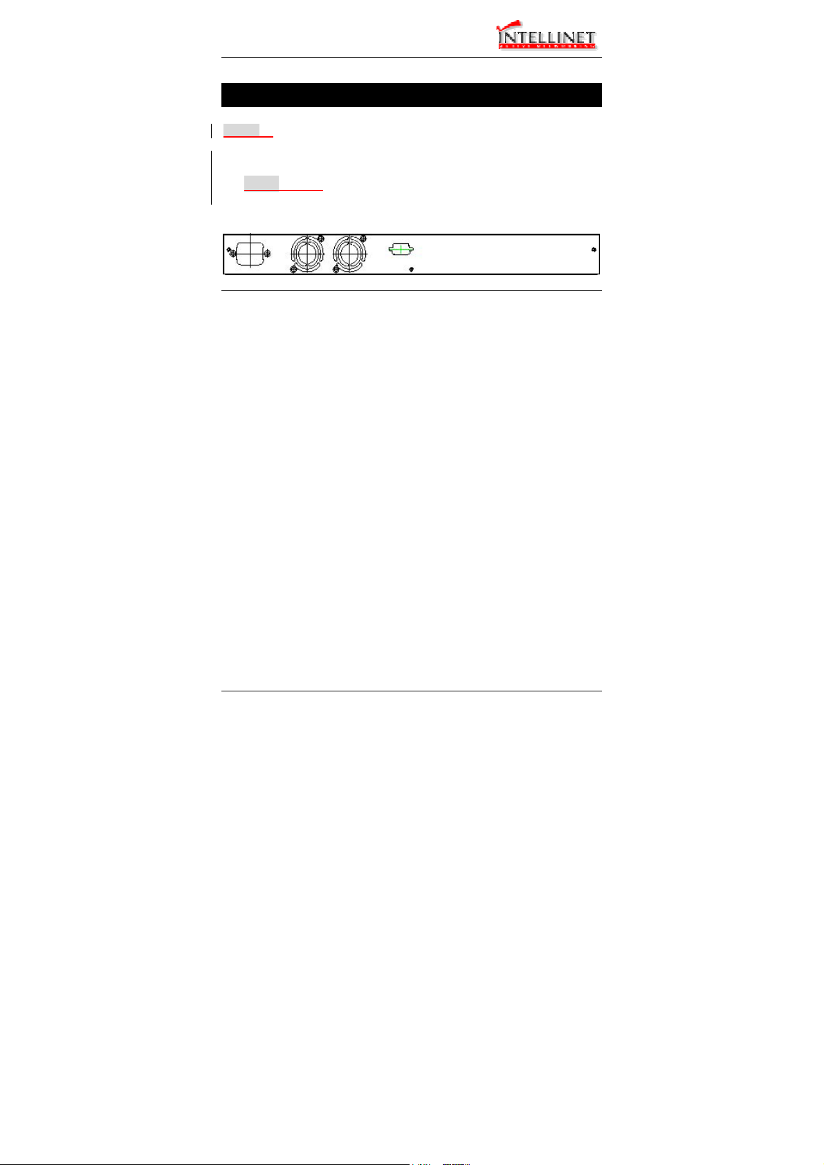
Connecting to Power
Step 1: Connect the supplied AC power cord to the receptacle on the back
of the switch, and then plug it into a standard AC outlet with a
voltage range from 100 to 240 Vac.
z Step 2: Disconnect the power cord if you want to shut down the
switch.
Rear view
12 User’s Manual
Page 13

Manageable Gigabit Switch
Connecting to Your Network
Cable Type & Length
It is necessary to follow the cable specifications below when connecting
the switch to your network. Use appropriate cables that meet your
speed and cabling requirements.
Cable Specifications
User’s Manual 13
Page 14

Manageable Gigabit Switch
Speed Connector
Port
Cable Max.
Speed
Half/Full
Duplex
10BaseT RJ-45 10/20 Mbps 2-pair
100BaseTX RJ-45 100/200
100BaseFX
(*Wavelength of
850nm)
100BaseFX
(*Wavelength of
1300nm)
1000BaseT RJ-45 1000/2000
(*Wavelength of
850nm)
(*Wavelength of
1300nm)
ST, SC, VF45, MT-RJ
SC 100/200
SC 1000/2000
SC 1000/2000
SC 1000/2000
SC 1000/2000
Mbps
100/200
Mbps
Mbps
Mbps
Mbps
Mbps
Mbps
Mbps
UTP/STP
Cat. 3, 4, 5
2-pair
UTP/STP
Cat. 5
62.5/125µm
multi-mode
fiber
10/125µm
single-mode
fiber
4-pair
UTP/STP
Cat. 5
62.5/125µm
multi-mode
fiber
50/125µm
multi-mode
fiber
62.5/125µm
multi-mode
fiber
10/125µm
single-mode
fiber
Distance
100 m
100 m
2 km
75 km
100 m
220 m 1000BaseSX
550 m
550 m 1000BaseLX
20 km
14 User’s Manual
Page 15

Manageable Gigabit Switch
Cabling
Step 1: First, ensure the power of the switch and end devices is turned off.
<Note> Always ensure that the power is off before any installation.
Step 2: Prepare cable with corresponding connectors for each type of port
<Note> To connect two regular RJ-45 ports between switches or hubs, you
Step 3: Consult Cable Specifications Table on previous page for cabling
Step 4: Connect one end of the cable to the switch and the other end to a
Step 5: Once the connections between two end devices are made
in use.
need a cross-over cable.
requirements based on connectors and speed.
desired device.
successfully, turn on the power and the switch is operational.
User’s Manual 15
Page 16

Manageable Gigabit Switch
Switch Management
This chapter explains the methods that you can use to configure
management access to the switch. It describes the types of
management applications and the communication and management
protocols that deliver data between your management device
(workstation or personal computer) and the system. It also contains
information about port connection options.
This chapter covers the following topics:
• Management Access Overview
• Key Concepts
• Key Guidelines for Implementation
• Administration Console Access
• Web Management Access
• SNMP Access
• Standards, Protocols, and Related Reading
Management Access Overview
The switch gives you the flexibility to access and manage the
switch using any or all of the following methods.
The administration console and web browser interface support are
embedded in the switch software and are available for immediate
use.
16 User’s Manual
Page 17

Manageable Gigabit Switch
Administration Console
The administration console is an internal, character-oriented, menudriven user interface for performing system administration such as
displaying statistics or changing option settings.
Using this method, you can view the administration console from a
terminal, personal computer, Apple Macintosh, or workstation
connected to the switch’s console port.
There are two ways to use this management method: direct access
or modem access. The following sections describe these methods.
Direct Access
Direct access to the administration console is achieved by directly
connecting a terminal or a PC equipped with a terminal-emulation
program (such as HyperTerminal) to the switch console port.
When using the management method, configure the terminal-emulation
program to use the following parameters (you can change these settings
after login):
[DEFAULT PARAMETERS]
♦ 115,200bps
♦ 8 data bits
♦ No parity
♦ 1 stop bit
This management method is often preferred because you can remain
connected and monitor the system during system reboots. Also, certain
error messages are sent to the serial port, regardless of the interface
through which the associated action was initiated. A Macintosh or PC
attachment can use any terminal-emulation program for connecting to
the terminal serial port. A workstation attachment under UNIX can use
an emulator such as TIP.
User’s Manual 17
Page 18

Manageable Gigabit Switch
Modem Access
You can access the switch’s administration console from a PC or
Macintosh using an external modem attached to the console port. The
switch management program provides Console Port screen, accessible
from the Basic Management screen, that lets you configure parameters
for modem access.
When you have configured the external modem from the administration
console, the switch transmits characters that you have entered as
output on the modem port. The switch echoes characters that it receives
as input on the modem port to the current administration console
session. The console appears to be directly connected to the external
modem.
Web Management
The switch provides a browser interface that lets you configure and
manage the switch remotely.
After you set up your IP address for the switch, you can access the
switch’s web interface applications directly in your web browser by
entering the IP address of the switch. You can then use your web
browser to list and manage switch configuration parameters from
one central location, just as if you were directly connected to the
switch’s console port.
Web Management requires either Microsoft Internet Explorer 4.01
or later or Netscape Navigator 4.03 or later.
SNMP-Based Network Management
You can use an external SNMP-based application to configure and
manage the switch. This management method requires the SNMP
agent on the switch and the SNMP Network Management Station
to use the same community string. This management method, in
fact, uses two community strings: the get community string and the
set community string. If the SNMP Network management station
18 User’s Manual
Page 19

Manageable Gigabit Switch
only knows the set community string, it can read and write to the
MIBs. However, if it only knows the get community string, it can
only read MIBs. The default get and set community strings for
the switch are public.
Protocols
The switch supports the following protocols:
VIRTUAL TERMINAL PROTOCOLS, SUCH AS TELNET
A virtual terminal protocol is a software program, such as Telnet, that allows
you to establish a management session from a Macintosh, a PC, or a UNIX
workstation. Because Telnet runs over TCP/IP, you must have at least one
IP address configured on the switch before you can establish access to it
with a virtual terminal protocol.
<Note> Terminal emulation is different from a virtual terminal protocol in that
SIMPLE NETWORK MANAGEMENT PROTOCOL (SNMP)
SNMP is the standard management protocol for multivendor IP networks.
SNMP supports transaction-based queries that allow the protocol to format
messages and to transmit information between reporting devices and datacollection programs. SNMP runs on top of the User Datagram Protocol
(UDP), offering a connectionless-mode service.
you must connect a terminal directly to the console port.
Management Architecture
All of the management application modules use the same
Messaging Application Programming Interface (MAPI). By
unifying management methods with a single MAPI, configuration
parameters set using one method (e.g. console port) are
immediately displayed the other management methods (e.g. SNMP
agent of web browser).
The management architecture of the switch adheres to the IEEE
open standard. This compliance assures customers that the switch is
compatible with, and will interoperate with other solutions that
adhere to the same open standard.
User’s Manual 19
Page 20

Manageable Gigabit Switch
Menu-Driven Console Management
The switch provides a menu-driven console interface for
configuration purposes. The switch can be configured either locally
through its RS-232 port or remotely via a Telnet session. For the
later, you must specify an IP address for the switch first.
This chapter describes how to configure the switch using its menudriven console.
* For initial IP settings, you must configure the switch through its
RS232 port.
Logging on to the switch
At the screen prompt
Login:
Password:
LOGIN NAME
Enter the console interface factory default console name admin.
PASSWORD
Enter the factory default password (no password, press <Enter> directly).
Or enter a user-defined password if you followed the instructions later and
changed the factory default password.
Factory Default Password: no password, press <Enter> directly.
<Note> Only one console and three telnet users can log on to the switch
concurrently. However, it is not recommended that multiple users
modify the configuration at the same time.
20 User’s Manual
Page 21

Manageable Gigabit Switch
Switch Management Screen
BASIC MANAGEMENT
Basic management activities.
ADVANCED MANAGEMENT
Advanced management activities.
LOGOUT
Highlight this option and press Enter to log out.
SAVE SETTINGS
Highlight this option and press Enter to save the current settings and remain
in the configuration program.
RESTORE DEFAULT SETTINGS
Highlight this option and press Enter to restore the factory default settings.
REBOOT
Highlight this option and press Enter to reboot.
User’s Manual 21
Page 22

Manageable Gigabit Switch
Navigating Through the Console Interface
The console interface consists of a series of menu boxes. Each
menu box has several options, which are listed vertically. Move the
highlight to select an option as you wish; press the Enter key to
activate that option.
Press this key… To
Up Arrow or K*
Down Arrow or J*
Tab Move the highlight between screens
Enter Select the highlighted option
Esc Move to a previous menu
Move the highlight one line up in a menu
box
Move the highlight one line down in a menu
box
<Note> * Remember to release the <Caps Lock> key if you press <K> or <J>
and cannot move the highlight on the screen.
Performing Basic Management Activities
Basic management activities consist of General, LAN Port, and
Console Port tasks.
22 User’s Manual
Page 23
Manageable Gigabit Switch
Start with Selection Menu
Step 1: Highlight [Basic Management] from [Switch Management] screen
Step 2: Highlight a desired option and press <Enter>. Or press <Esc> to
User’s Manual 23
and press <Enter>. The [Basic Management] screen appears:
exit.
Page 24

Manageable Gigabit Switch
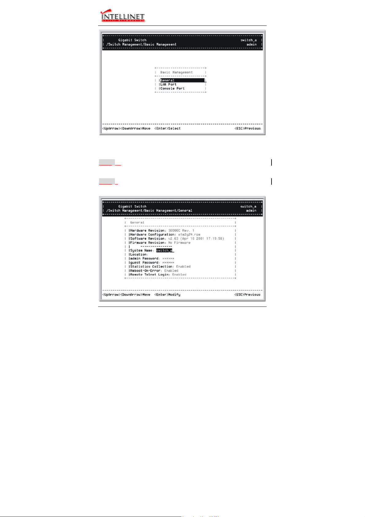
General Management Configurations
Step 1: Highlight [General] from [Basic Management] screen and press
System Name
<Enter>.
Step 2: System Name is highlighted. Press <Enter> if you want to change
Location
it.
Step 3: Move to highlight Location and press <Enter> if you want to
admin Password
change it.
Step 4: Move to highlight admin Password and press <Enter> if you want
guest Password
to change it.
Step 5: Move to highlight guest Password and press <Enter> if you want
Statistics Collection
to change it.
Step 6: Move to highlight Statistics Collection and press <Enter> if you
Reboot-On-Error
want to change it, Disabled or Enabled.
Step 7: Move to highlight Reboot-On-Error and press <Enter> if you want
Remote Telnet Login
to change it, Disabled or Enabled.
Step 8: Move to highlight Remote Telnet Login and press <Enter> if you
want to change it, Disabled or Enabled.
Return to Basic Management
Step 9: Press <Esc> to return to [Basic Management] screen when
completed.
24 User’s Manual
Page 25
Manageable Gigabit Switch
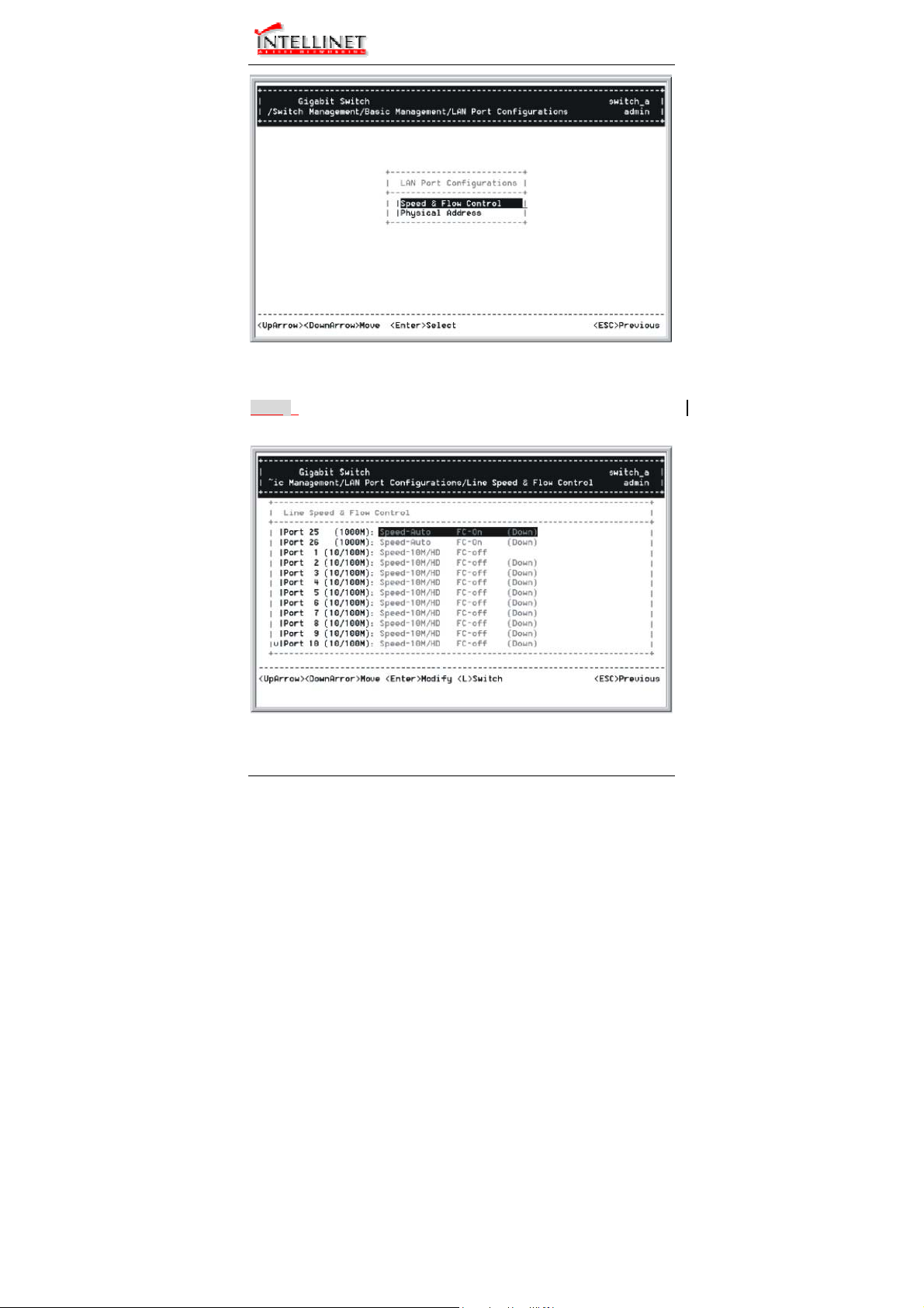
LAN Port Configurations
Step 1: Highlight [LAN Port] from [Basic Management] screen and press
SPEED & FLOW CONTROL
User’s Manual 25
<Enter>.
Page 26
Manageable Gigabit Switch
Step 2: Speed & Flow Control is highlighted. Press <Enter> if you want
to set speed or flow control on port.
Step 3: Highlight All (10/100M or 1000M) Ports and press <Enter> to
configure at one time. Otherwise, move to highlight each port and
press <Enter> to configure individually.
Step 4: Port Setting Options screen appears. Highlight Speed & Flow
Line Speed
Control and press <Enter>.
Step 5: For Line Speed, move to highlight a desired setting from Speed
Options and press <Enter>.
<Note> In the Speed Options, Auto denotes auto negotiation on speed and
duplex mode, HD denotes half-duplex, and FD denotes full-duplex.
Step 6: Press <Esc> to previous screen. Highlight Flow Control and
Flow Control
press <Enter>
Step 7: For Flow Control, move to highlight a desired setting from the
Flow Cntl Options and press <Enter>.
Step 8: Press <Esc> to a previous screen as shown in Step 3.
26 User’s Manual
Page 27
Manageable Gigabit Switch
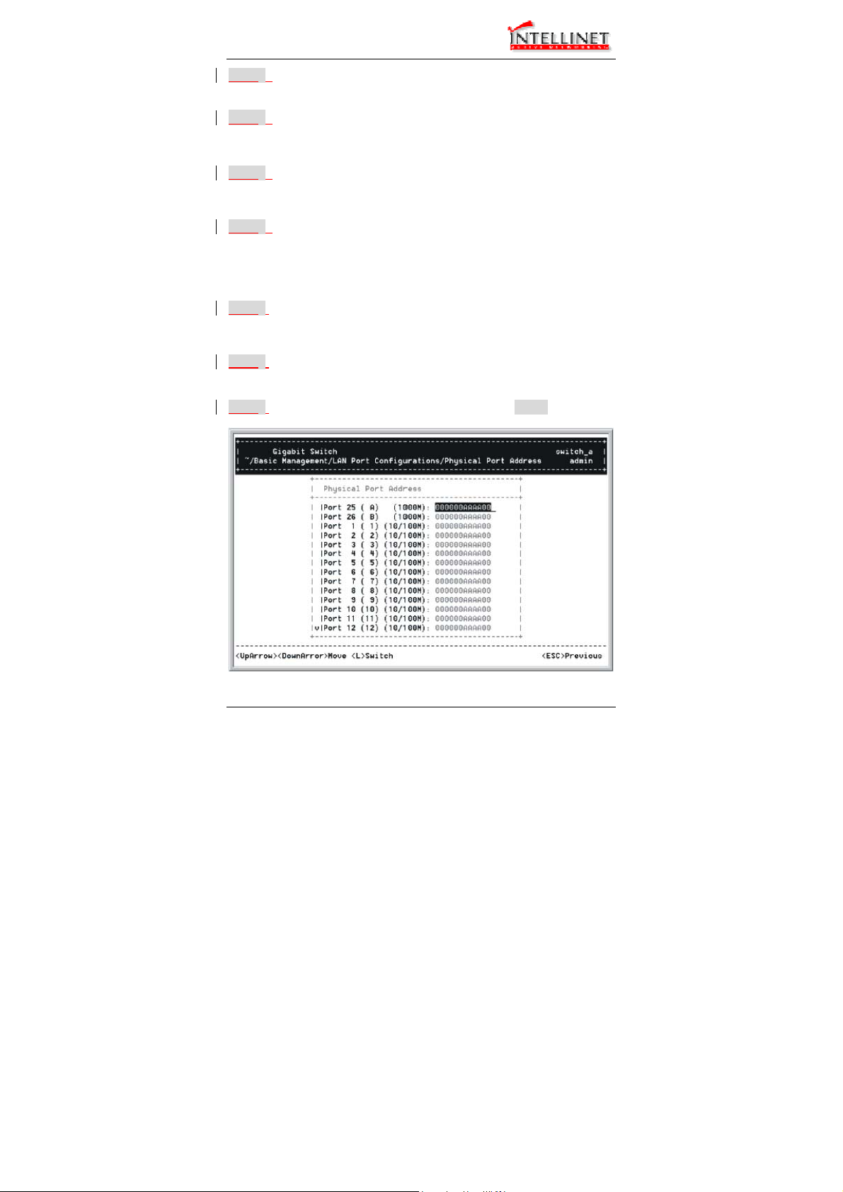
PHYSICAL PORT ADDRESS
Step 9: Press <Esc> to a previous screen as shown in Step 1.
Step 10: Move to highlight Physical Address to view physical port address.
Return to Basic Management
Step 11: Press <Esc> to return to [Basic Management] screen when
completed.
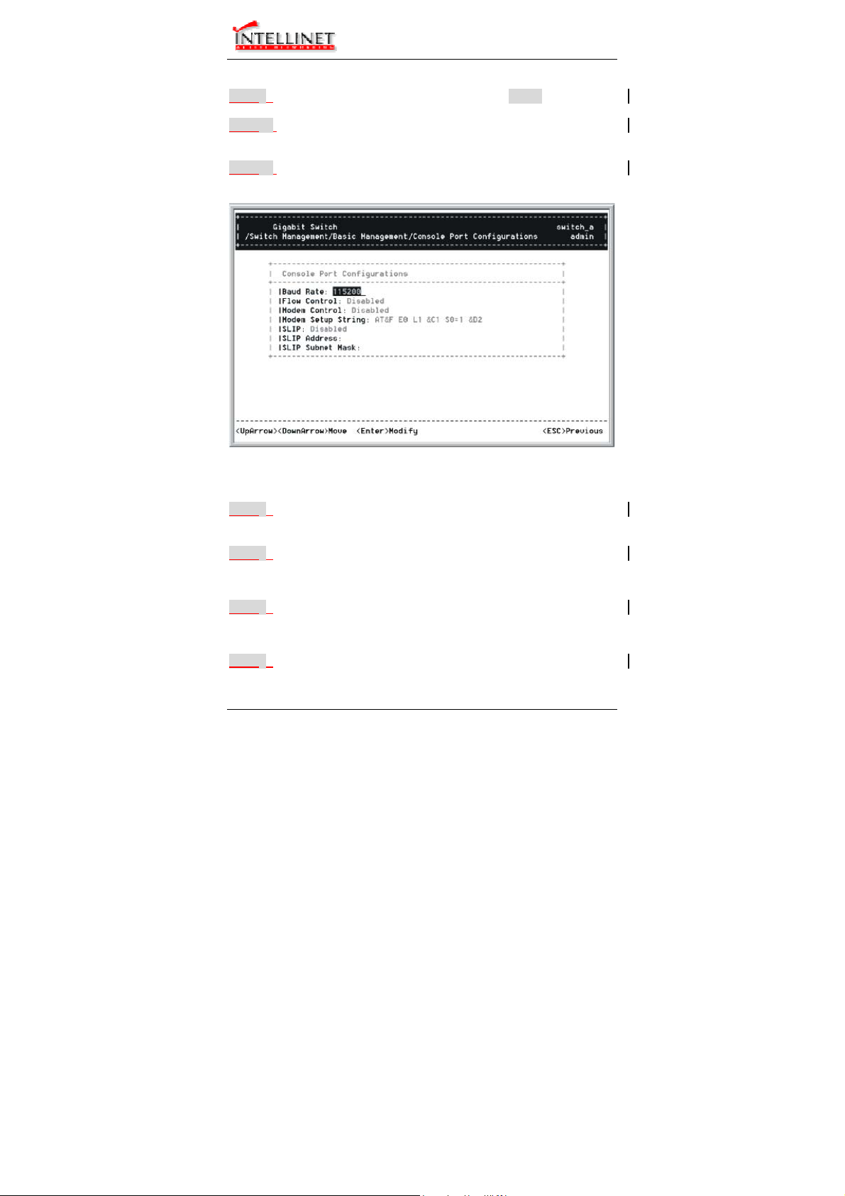
Console Port Configurations
Step 1: Move to highlight [Console Port] from [Basic Management] screen.
Baud Rate
Step 2: Baud Rate is highlighted. Press <Enter> if you want to change the
Flow Control
Step 3: Move to highlight Flow Control and press <Enter> if you want to
Modem Control
Step 4: Move to highlight Modem Control and press <Enter> to decide a
User’s Manual 27
current console baud rate.
change the current flow control method.
console modem connection, Disabled or Enabled.
Page 28

Manageable Gigabit Switch
Modem Setup String
Step 5: When a modem connection is enabled, move to highlight Modem
Setup String and press <Enter>. Decide whether you want to use
<Note> Default Setup String configures the modem to auto answer. It works
SLIP
Default or Custom Setup String.
for all Hayes compatible modems.
Step 6: Move to highlight SLIP and press <Enter> if you want to change it,
<Note> If you enable SLIP, a message tells you that the console port
SLIP Address
Disabled or Enabled.
becomes accessible only through the SLIP protocol after you logout
from the current console screen.
Step 7: Move to highlight SLIP Address and press <Enter> if you want to
SLIP Subnet Mask
set it.
Step 8: When SLIP IP address is entered, move to highlight SLIP Subnet
<Note> You must enter a SLIP address before you can enter a SLIP subnet
Mask and press <Enter>. Enter a suitable subnet mask.
mask.
Return to Basic Management
Step 9: Press <Esc> to return to [Basic Management] screen when
completed.
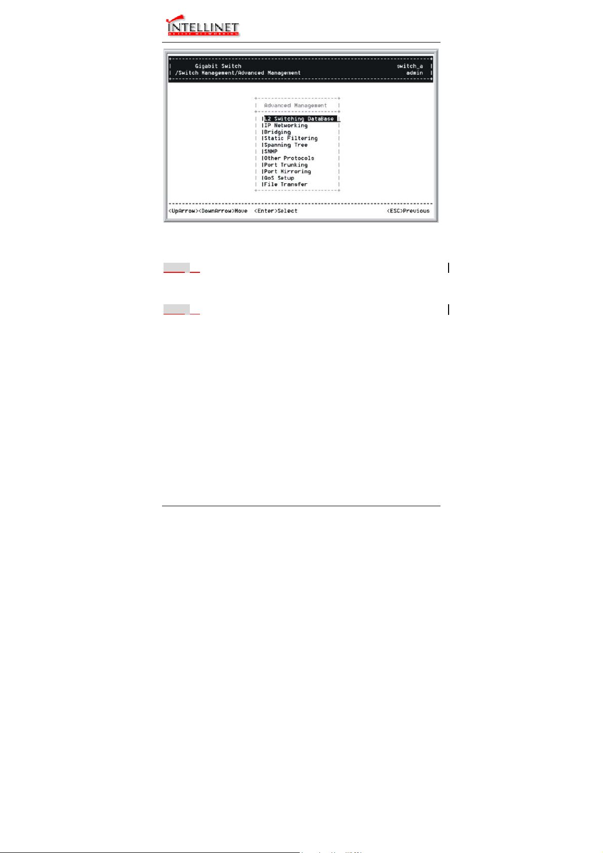
Performing Advanced Management Activities
Advanced management activities consist of L2 Switching DataBase
/ IP Networking / Bridging / Static Filtering / Spanning Tree /
SNMP / Other Protocols / Port Mirroring / QoS Setup / File
Transfer.
28 User’s Manual
Page 29
Manageable Gigabit Switch
Start with Selection Menu
Step 1: Highlight [Advanced Management] from [Switch Management]
Step 2: Move to highlight a desired option and press <Enter>.
L2 SWITCHING DATABASE
View and change VLAN, MAC address, IP multicast group, and port
perspectives.
IP NETWORKING
View and change IP settings, ARP and routing table parameters, DHCP
gateway settings, and ping settings.
BRIDGING
View and change the aging period for a MAC address and the flood limit for
all ports.
STATIC FILTERING
View / add / delete / search all source or destination MAC addresses to be
filtered.
User’s Manual 29
screen and press <Enter>. The [Advanced Management] screen
appears:
Or press <Esc> to exit.
Page 30
Manageable Gigabit Switch
SPANNING TREE
View and change spanning tree configurations, ports states, path costs, and
port priorities.
SNMP
View and change the SNMP configuration.
OTHER PROTOCOLS
View and change GVRP and IGMP settings.
PORT MIRRORING
Mirror one port to another.
QOS SETUP
Specify Quality of Service parameter.
FILE TRANSFER
Send files using the TFTP or Kermit protocol.
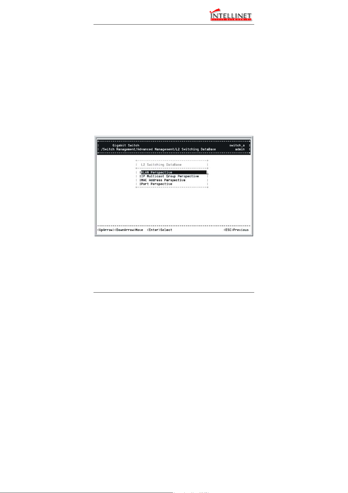
L2 Switching DataBase
Highlight [L2 Switching DataBase] from [Advanced Management] screen
and press <Enter>.
30 User’s Manual
Page 31

Manageable Gigabit Switch
VLAN PERSPECTIVE
Step 1: The VLAN Perspective is highlighted. Press <Enter> to view VLAN
info of the default VLAN or if you want to obtain a VLAN
perspective instead of the default VLAN.
<Note> Default VLAN:
The IEEE802.1Q standard defines VLAN ID #1 as the default VLAN. The
default VLAN includes all the ports as the factory default. The default
VLAN’s egress rule restricts the ports to be all untagged, so it can, by
default, be easily used as a simple 802.1D bridging domain. The
default VLAN’s domain shrinks as untagged ports are defined in other
VLANs.
Create VLAN
Step 2: Press <Shift> and [+] on keypad to enter New VLAN Settings.
Enter new VLAN ID and VLAN name.
<Note> “Remote” is appended to the VLAN ID automatically if the VLAN is
learned from a remote switch.
Add New Switch Ports
Step 3: Press <Esc> and appears the following screen. Press <Shift> and
[+] to add new switch ports to the newly created VLAN.
Step 4: Move to highlight a suitable option from Port Options and press
<Enter>, e.g. Untagged Ports.
User’s Manual 31
Page 32

Manageable Gigabit Switch
Step 5: From Select Untagged Ports, press <Enter> to select All Ports
or move to highlight each port individually and press <Enter>.
Similar procedure when you select Tagged Ports and Forbidden
<Note> If you added untagged ports and want to now add tagged ports or
Ports in Step 4.
forbidden ports, or vice versa, repeat Step 4 and Step 5.
Step 6: Press <Esc> to a previous screen as shown in Step 1.
Delete VLAN
Step 7: Delete VLAN: highlight a VLAN ID and press [-] to delete it.
Note that you cannot delete the default VLAN.
Step 8: Press <Esc> to a previous screen as shown in Step 1 when
VLAN Info
completed with deleting a VLAN.
Step 9: Highlight an existing VLAN and press <Enter> to view VLAN
information.
Step 10: Move to highlight VLAN Activities and press <Enter> to view or
search activity information.
Step 11: Return to Step 9. Move to highlight VLAN Settings and press
<Enter>. The screen appears as shown in Step 3 for adding or
deleting switch ports.
32 User’s Manual
Page 33

Manageable Gigabit Switch
IP MULTICAST GROUP PERSPECTIVE
Step 1: Move to highlight [IP Multicast Group Perspective] from [L2
Switching DataBase] screen and press <Enter>.
Step 2: Move to highlight an address to view information associated with
this IP multicast group.
MAC ADDRESS PERSPECTIVE
Step 1: Move to highlight [MAC Address Perspective] from [L2 Switching
DataBase] screen and press <Enter>.
Step 2: Enter a MAC address to view characteristics information,
corresponding VLANs, and corresponding ports in the switching
User’s Manual 33
database.
Page 34

Manageable Gigabit Switch
PORT PERSPECTIVE
Step 1: Move to highlight [Port Perspective] from [L2 Switching DataBase]
screen and press <Enter>.
You can view VLAN activities and RMON statistics here.
Per Port VLAN Activities
Step 2: Per Port VLAN Activities is highlighted. Press <Enter>.
Step 3: Move to highlight a port and press <Enter>.
E.g. select Port A to view corresponding VLAN Activities.
Step 4: View or search by MAC address individually.
Step 5: Press <Esc> to return to a previous screen as shown in Step 1.
Per Port Statistics
Step 6: Move to highlight Per Port Statistics and press <Enter>.
Step 7: Move to highlight a port and press <Enter>.
Press <R> to reset counter for this port.
Per Port MAC Limit
Step 8: Move to highlight Per Port MAC Limit and press <Enter>.
Step 9: Move to highlight a port and press <Enter>.
34 User’s Manual
Page 35

Manageable Gigabit Switch
IP Networking
Move to highlight [IP Networking] from [Advanced Management] screen
and press
<Enter>.
User’s Manual 35
Page 36

Manageable Gigabit Switch
IP & RIP SETTINGS
Step 1: Highlight [IP & RIP Settings] from [IP Networking] and press
<Enter>.
Step 2: The screen shows a list of VLAN IDs, IP addresses, subnet masks,
proxy ARPs, and RIPs currently defined.
Step 3: Move to highlight the row that contains the parameters you want to
change, and then press <Enter>.
Step 4: Move to highlight a parameter you want to change, and then press
Otherwise, you may press [-] to delete that parameter.
Initial IP Settings
<Enter> for modifications.
Step 5: Move to highlight IP Address and press <Enter>.
Step 6: Type an IP address and press <Enter>
Step 7: Press <Esc> until you return to [Switch Management] screen.
Make sure you save the settings before you log out.
ARP TABLE SETTING
Step 1: Move to highlight [ARP Table] from [IP Networking] and press
<Enter>. The screen shows the ARP table entries that have been
defined or learned.
36 User’s Manual
Page 37

Manageable Gigabit Switch
y
Add/Delete Static ARP Table Entries
Step 2: Press <Shift> and [+] on keypad to add an entry into the ARP
Enter Internet/Physical Addresses then.
Table.
Step 3: Press [-] on keypad if you want to delete a static entry from the
ARP Table.
* No precautionary message appears before you delete an entry from
the ARP table.
* Be sure
ou want to delete it before doing so.
Search for ARP Table Entries
Step 4: Press <S> to search a static entry. You can search by Internet
address or physical address.
ROUTING TABLE
Step 1: Move to highlight [Routing Table] from [IP Networking] and press
<Enter>. The screen shows the Routing Table allows you to view,
add, delete or search a particular routing path.
User’s Manual 37
Page 38

Manageable Gigabit Switch
Routing Table Columns
38 User’s Manual
Page 39

Manageable Gigabit Switch
Column Description
Network The IP subnetwork address to which the switch can
route packets.
Mask The related IP subnetwork mask to which the switch
can route packets.
Gateway
The IP address of the router at the next hop.
Metric The number of hops needed between the switch and
the destination network.
VLAN The VLAN within which the gateway or destination
resides.
Type
The IP route type for the IP subnetwork. There are six
IP route types:
Direct
Remote
Myself
A directly connected subnetwork.
A remote IP subnetwork or host address.
A switch IP address on a specific IP
subnetwork.
A subnetwork broadcast address.
An IP multicast address.
An illegal IP address to be filtered.
A manually configured routing entry.
A routing entry set via SNMP.
A routing entry obtained via ICMP
Protocol
Bcast
Mcast
Martian
Indicates one of the following:
Local
NetMgmt
ICMP
redirect.
RIP
A routing entry learned via the RIP
protocol.
Other
A protocol other than one of the other
four listed above.
Add/Delete Routing Table Entries
Step 2: Press <Shift> and [+] on keypad to enter Route Options as
shown below.
Step 3: Press [-] to delete an entry in the routing table.
User’s Manual 39
Page 40

Manageable Gigabit Switch
y
* No precautionary message appears before you delete an entry
from the routing table.
* Be sure
Search for Routing Table Entries
ou want to delete it before doing so.
Step 4: Press <S> to search a network address. Enter the network
address you want you are looking for.
DHCP GATEWAY SETTINGS
Step 1: Move to highlight [DHCP Gateway Settings] from [IP Networking]
and press <Enter>.
Step 2: Move to highlight a row you want to change the DHCP Gateway
Add/Delete Relay IP
Settings, and press <Enter>
Step 3: Press <Shift> and [+] on keypad to add a relay IP. Choose a
suitable interface or All Interfaces from Select Outbound Relay
Interfaces.
DHCP Gateway Options
Otherwise, you may press [-] on keypad to delete a relay IP.
* No precautionary message appears before you delete a relay IP.
* Be sure you want to delete it before doing so.
Step 4: Move to highlight DHCP Gateway and press <Enter>.
40 User’s Manual
Page 41

Manageable Gigabit Switch
Maximum Hops
Decide to have it Disabled or Enabled.
Step 5: Move to highlight Maximum Hops and press <Enter>
Step 6: Enter decimal number (1-16) to configure the maximum number of
Delay (sec)
Step 7: Move to highlight Delay (sec) and press <Enter>.
hops.
Step 8: Enter decimal number (0-65535) configure the delay in seconds.
Preferred Server
Step 9: Move to highlight Preferred Server and press <Enter>.
Step 10: Enter IP address for the Preferred Server.
Step 11: To specify up to three more Preferred Servers, repeat the above
steps.
PING SETTINGS
Step 1: Move to highlight [Ping] from [IP Networking] and press <Enter>.
User’s Manual 41
Page 42

Manageable Gigabit Switch
Host
Step 2: Move to highlight Host and press <Enter>.
Step 3: Enter 4 decimal bytes (dot separated) as the IP address to ping.
Count
Step 4: Move to highlight Count and press <Enter>.
Step 5: Specify a packet count number from 1 to 999, or type 0 for an
Size (bytes)
Step 6: Move to highlight Size and press <Enter>.
infinite packet count. Press <Enter>.
Step 7: Specify a packet size from 0-1500. Press <Enter>.
Timeout (sec)
Step 8: Move to highlight Timeout and press <Enter>.
Step 9: Specify a timeout value from 1-999. Press <Enter>.
Step 10: Press <Esc> to start to ping when completed with the ping
parameters.
42 User’s Manual
Page 43

Manageable Gigabit Switch
Bridging
Move to highlight [Bridging] from [Advanced Management] screen, and
press <Enter>.
AGING TIME
Step 1: Move to highlight Aging Time and press <Enter>.
Aging Options
Step 2: Set Aging Time is highlighted. Press <Enter>.
Enter a decimal number as bridge aging period in seconds.
Step 3: Otherwise, you may move to highlight No Aging, and press
FLOOD LIMIT FOR ALL PORTS
Step 1: Move to highlight [Flood Limit for All ports] and press <Enter>.
Flooding Options
Step 2: Set Flood Limit is highlighted. Press <Enter>.
Enter a decimal number as flood limit in packets per second.
Step 3: Otherwise, you may move to highlight Unlimited, and press
<Enter>.
<Enter>.
User’s Manual 43
Page 44

Manageable Gigabit Switch
Static Filtering
Move to highlight [Static Filtering] from [Advanced Management] screen,
and press <Enter>.
SOURCE/DESTINATION MAC ADDRESS OUT-FILTERS
Step 1: Move to highlight source MAC addresses or destination MAC
addresses for static filtering, and press <Enter>.
44 User’s Manual
Page 45

Manageable Gigabit Switch
y
Add/Delete/Search
Step 2: Press <Shift> and [+] on keypad to add a specific MAC address to
Press [-] to delete a specific MAC address from being filtered.
Press <S> to search through current list of MAC addresses in the
be filtered.
static filtering database. The static filtering database maximum
capacity is 64.
* No precautionary message appears before you delete a specific MAC
address from being filtered.
* Be sure
ou want to delete it before doing so.
MAC Address In-Filters
Move to highlight [Static Filtering] from [Advanced Management] screen,
and press <Enter>.
MAC ADDRESS IN-FILTERS
Step 1: Move to highlight MAC addresses In-Filters and press <Enter>.
Add/Delete/Search
Step 2: Press <Shift> and [+] on keypad to add a specific MAC address to
Press [-] to delete a specific MAC address from being filtered.
User’s Manual 45
be filtered.
Page 46

Manageable Gigabit Switch
y
Press <S> to search through current list of MAC addresses in the
static filtering database. The static filtering database maximum
capacity is 64.
* No precautionary message appears before you delete a specific MAC
address from being filtered.
* Be sure
ou want to delete it before doing so.
Spanning Tree Functions
Move to highlight [Spanning Tree] from [Advanced Management] screen,
and press <Enter>.
46 User’s Manual
Page 47

Manageable Gigabit Switch
SPANNING TREE CONFIGURATIONS
Step 1: Move to highlight [Spanning Tree Configurations] if you want to
change Spanning Tree Protocol Configurations.
Spanning Tree Protocol
Step 2: Press <Enter> to enter Spanning Tree Options.
Decide to have it Disabled or Enabled.
Bridge Priority
Step 3: Move to highlight Bridge Priority and press <Enter>.
Type a decimal number for the bridge priority and press <Enter>.
Hello Time (sec)
Step 4: Move to highlight Hello Time and press <Enter>.
Type a decimal number for the hello time and press <Enter>.
Max Age (sec)
Step 5: Move to highlight Max Age and press <Enter>.
Forward Delay (sec)
Type a decimal number for the max age.
Step 6: Move to highlight Forward Delay and press <Enter>.
User’s Manual 47
Type a decimal number for the forward delay.
Page 48

Manageable Gigabit Switch
SPANNING TREE PORT STATES
Step 1: Move to highlight [Spanning Tree Port States] if you want to
change per port administration status, and press <Enter>.
Step 2: Move to highlight a port if you want to change its administration
‘Disabled (Link Down)’ denotes Admin Status Up without a link.
‘Forwarding’ denotes Admin Status Up with a link.
‘Admin Status Down’ denotes no TX/RX transmission allowed
‘Admin Status Up’ denotes TX/RX transmission allowed.
48 User’s Manual
status, and press <Enter>.
Page 49

Manageable Gigabit Switch
SPANNING TREE PATH COSTS
Step 1: To change the path cost, move to highlight [Spanning Tree Path
Costs] and press <Enter>.
Step 2: Move to highlight All Ports or each port individually, and press
<Enter>. For new path cost, type a decimal number and press
<Enter>.
User’s Manual 49
Page 50

Manageable Gigabit Switch
SPANNING TREE PORT PRIORITIES
Step 1: To change the priority level per port, move to highlight [Spanning
Tree Port Priorities] and press <Enter>.
Step 2: Move to highlight All Ports or each port individually, and press
<Enter>. For new priority value, type a decimal number from 0-255,
and press <Enter>. A low value gives the port a greater likelihood
of becoming a Root port.
SNMP Functions
Move to highlight [SNMP] from [Advanced Management] screen, and
press <Enter>.
SNMP Options
Step 1: Move to highlight SNMP and press <Enter>.
Decide to have it Disabled or Enabled.
Get Community Name
Step 2: Move to highlight Get Community Name and press <Enter>.
Enter text and press <Enter>.
Set Community Name
Step 3: Move to highlight Set Community Name and press <Enter>.
Enter text and press <Enter>.
50 User’s Manual
Page 51

Manageable Gigabit Switch
Trap Community Name
Step 4: Move to highlight Trap Community Name 1 and press <Enter>.
Enter text and press <Enter>.
Repeat to specify up to three more trap community names.
Trap Host IP Address
Step 5: Move to highlight Trap Host 1 IP Address and press <Enter>.
Type an IP address for trap host 1 and press <Enter>
Repeat to specify up to three more trap host IP addresses
Cold Start Trap
Step 6: Move to highlight Cold Start Trap and press <Enter>.
Decide to have it Disabled or Enabled.
Warm Start Trap
Step 7: Move to highlight Warm Start Trap and press <Enter>.
Decide to have it Disabled or Enabled.
Link Down Trap
Step 8: Move to highlight Link Down Trap and press <Enter>.
Decide to have it Disabled or Enabled.
Link Up Trap
Step 9: Move to highlight Link Up Trap and press <Enter>.
Decide to have it Disabled or Enabled.
Authentication Failure Trap
Step 10: Move to highlight Authentication Failure Trap and press <Enter>.
Decide to have it Disabled or Enabled.
Rising Alarm Trap
Step 11: Move to highlight Rising Alarm Trap and press <Enter>.
Decide to have it Disabled or Enabled.
Falling Alarm Trap
Step 12: Move to highlight Falling Alarm Trap and press <Enter>.
Decide to have it Disabled or Enabled.
Topology Change Trap
Step 13: Move to highlight Topology Change Trap and press <Enter>.
Decide to have it Disabled or Enabled.
User’s Manual 51
Page 52

Manageable Gigabit Switch
Other Protocols
Move to highlight [Other Protocols] from [Advanced Management]
screen, and press <Enter>.
GVRP
Step 1: Move to highlight GVRP and press <Enter>.
Step 2: Decide to have it Disabled or Enabled.
IGMP
Step 1: Move to highlight IGMP and press <Enter>.
Step 2: Decide to have it Disabled or set in either Passive or Active mode.
52 User’s Manual
Page 53

Manageable Gigabit Switch
Port Mirroring
Move to highlight [Port Mirroring] from [Advanced Management] screen,
and press <Enter>.
Mirror To
Step 1: Press <Enter> to enter Mirror To Options, listing the ports that
Step 2: Move to highlight the port you want to mirror to and press <Enter>.
Mirror From
Step 3: Press <Enter> to enter Mirror From Options, listing the ports that
Step 4: Move to highlight the port you want to mirror from and press
Mirror Mode
Step 5: Move to select Mirror Mode. From Mode Options, decide
Step 6: Press <Esc> when completed.
User’s Manual 53
can be mirrored to.
can be mirrored from.
<Enter>.
whether the port to be mirrored from will be receiving or
transmitting.
Page 54

Manageable Gigabit Switch
QoS Setup
Move to highlight [QoS Setup] from [Advanced Management] screen,
and press <Enter>.
Global Setting
Step 1: Move to highlight Global Setting and press <Enter>.
54 User’s Manual
Page 55

Manageable Gigabit Switch
Step 2: Move to highlight Diffserv Expedite Forwarding and press
<Enter>. Move to highlight to enable or disable Diffserv Expedite
Forwarding and press <Enter>.
Step 3: Move to highlight ToS/VLAN and press <Enter>. Highlight the
desired setting then press <Enter>.
Step 4: Move to highlight QoS Status and press <Enter>. Move to
highlight to enable or disable QoS Status and press <Enter>.
Step 5: Move to highlight WRED Drop Priority Setting and press <Enter>.
Move to highlight to Low Drop Percentage or High Drop
Percentage and press <Enter>.
Step 6: Press <Esc> when completed
Logical Port
Step 7: Move to highlight Logical Port and press <Enter>.
Step 8: Move to highlight User Define Port, Well-Known Port, or Range
Port and press <Enter>.
Step 9: Move to highlight the appropriate port and press <Enter>.
Step 10: Press <Esc> when completed
User’s Manual 55
Page 56

Manageable Gigabit Switch
VLAN
Step 11: Move to highlight VLAN and press <Enter> to specify the QoS
VLAN priority.
Step 12: Move to highlight Drop Priority or Transmit Priority and press
<Enter>.
Step 13: Press <Esc> when completed
56 User’s Manual
Page 57

Manageable Gigabit Switch
ToS
Step 14: Move to highlight TOS and press <Enter> to specify the ToS
priority.
Step 15: Move to highlight Drop Priority or Transmit Priority and press
<Enter>.
Step 16: Press <Esc> when completed
Profile
Step 17: Move to highlight Profile and press <Enter> to select a QoS
profile.
Step 18: Move to highlight Megabit Profile or Gigabit Profile and press
<Enter>.
Step 19: Press <Esc> when completed
User’s Manual 57
Page 58

Manageable Gigabit Switch
Port Configuration
Step 20: Move to highlight Port Configuration and press <Enter> to
specify the port configuration parameters.
Step 21: Move to highlight Active Profile, Fixed Drop Priority, or Fixed
Transmit Priority and press <Enter>.
Step 22: Press <Esc> when completed
58 User’s Manual
Page 59

Manageable Gigabit Switch
Rate Control
Step 23: Move to highlight Rate Control and press <Enter> to specify rate
control parameters.
Step 24: Move to highlight Rate Control, or Port Number and press
<Enter>.
Step 25: Press <Esc> when completed.
Sending and Receiving Files
Move to highlight [File Transfer] from [Advanced Management] screen,
and press <Enter>.
If you access the administration console by connecting an RS232 cable
directly to the console port at the back of the switch, you will see a [File
Transfer] screen.
RECEIVE FILE VIA TFTP
Step 1: Move to highlight Receive File Via TFTP and press <Enter>.
Step 2: Type the name of the file you intend to receive and press <Enter>.
Step 3: Move to highlight IP Address and press <Enter>.
Type the IP address from where the file will be obtained.
User’s Manual 59
Page 60

Manageable Gigabit Switch
Step 4: Press <Esc> when completed.
Step 5: A dialog box appears to ask if you want to transfer file now.
Highlight [Yes] and press <Enter> to start file transfer.
Otherwise, move to highlight [No] and press <Enter> to deny it.
Step 6: Press <Esc> to a previous screen.
SEND FILE VIA TFTP
Step 1: In [File Transfer] screen, move to highlight Send File Via TFTP
and press <Enter>.
Step 2: If the default File Type is not the one you intend to send, press
<Enter>. Select the file type you intend to send and press <Enter>.
Step 3: Repeat Step 3-5.
RECEIVE FILE VIA KERMIT
Step 1: In [File Transfer] screen obtained via console port, move to
highlight Receive File Via Kermit and press <Enter>.
Step 2: A dialog box appears to ask if you want to transfer file now.
Move to highlight [Yes] and press <Enter> to start file transfer.
Otherwise, highlight [No] and press <Enter> to deny it.
Step 3: Press <Esc> to a previous screen.
SEND FILE VIA KERMIT
Step 1: In [File Transfer] screen obtained via console port, move to
highlight Send File Via Kermit and press <Enter>.
Step 2: Move to highlight a file type you intend to send and press <Enter>.
Step 3: A dialog box appears to ask if you want to transfer file now.
Move to highlight [Yes] and press <Enter> to start file transfer.
Otherwise, highlight [No] and press <Enter> to deny it.
Step 4: Press <Esc> to a previous screen.
60 User’s Manual
Page 61

Manageable Gigabit Switch
Logout
To log out, highlight [Logout] from [Switch Management] screen
and press <Enter>. Please remember to save settings you have
changed before you log out.
Save Settings
To save the current settings and remain in the configuration
program, highlight [Save Settings] from [Switch Management] and
press <Enter>.
Restore Default Settings
To restore the factory default settings, highlight [Restore Default
Settings] from [Switch Management] and press <Enter>.
The switch will be rebooted after confirming Yes as to restore the
default settings.
Reboot
To reboot the switch, highlight [Reboot] from [Switch Management]
and press <Enter>.
User’s Manual 61
Page 62

Manageable Gigabit Switch
Web-Based Browser Management
The switch provides a web-based browser interface for configuring
and managing the switch. This interface allows you to access the
switch using a preferred web browser.
This chapter describes how to configure the switch using its webbased browser interface.
Logging on to the switch
SWITCH IP ADDRESS
In your web browser, specify the IP address of the switch.
LOGIN ID
Enter the factory default login ID: admin.
PASSWORD
Enter the factory default password (no password, press Enter directly).
Otherwise, enter a user-defined password if you followed the instructions
later and changed the factory default password.
62 User’s Manual
Page 63

Manageable Gigabit Switch
Understanding the Browser Interface
The web browser interface provides three point-and-click buttons at
the upper field of the screen for configuring and managing the
switch.
In addition, you can click any port on the switch image to view the
switch’s current speed, duplex, and activity status.
The Basic Setup/General parameters appear at the lower field of
the screen. These parameters can also be displayed by clicking
Basic Setup button and select General in sub-menu.
User’s Manual 63
Page 64

Manageable Gigabit Switch
FILE
Save settings configured in the browser interface / download upgraded
software via TFTP / reboot the switch / logout of the browser interface.
BASIC SETUP
Perform general, LAN port, and console port activities.
ADVANCED SETUP
Perform MAC address management / IP networking / per port statistics /
bridging / static MAC filters / IP multicast group / VLAN perspective /
Spanning Tree perspective / SNMP / other protocols / port mirroring / QoS
tasks.
Performing File Activities
Start with Selection Menu
Click the [File] button at the upper field of the main display, the menu
options appear.
SAVING SETTING
Step 1: Click Saving Setting to save your configuration settings.
64 User’s Manual
Page 65

Manageable Gigabit Switch
Step 2: When you click it, a message asks ”Are you sure you want to
RECEIVE FILE VIA TFTP
save setting? ”, click OK to save it or Cancel to abort it.
Step 1: Click Receive File Via TFTP on the [File] display
<Note> The TFTP protocol is used to download upgraded software to the
switch.
A VLAN with the proper IP address and routing path to the TFTP server
must be configured for the switch to access the specified TFTP server.
Step 2: For File Name, type the name of the file you intend to receive.
Step 3: For IP Address, type the IP address from where the file will be
Step 4: Click Receive Now! .
REBOOT
obtained.
Step 1: Click Reboot on the [File] display.
Step 2: When you click it, a message asks ”Are you sure you want to
save setting? ”, click OK to save it or Cancel to abort it.
LOGOUT
Step 1: Click Logout on the [File] display.
Step 2: When you click it, a message asks ”Are you sure you want to
save setting? ”, click OK to save it or Cancel to abort it.
User’s Manual 65
Page 66

Manageable Gigabit Switch
Performing Basic Setup Activities
Start with Selection Menu
Click the [Basic Setup] button at the upper field of the main display, the
menu options appear.
66 User’s Manual
Page 67

Manageable Gigabit Switch
GENERAL MANAGEMENT CONFIGURATION
Step 1: Click General and the screen shows the Basic Setup/General
System Name
parameters.
Step 2: Click in System Name text box on the field of Basic
Setup/General.
Step 3: Type a system name if it is blank, or replace the current system
Location
name with a new one.
Step 4: Click in Location text box on the field of Basic Setup/General.
Step 5: Type a location name if it is blank, or replace the current location
Statistic Collection
name with a new one.
Step 6: To enable or disable statistics collection at the switch, click the
Reboot-On-Error
appropriate option from Statistic Collection drop-down menu.
Step 7: To allow or prevent the switch from rebooting when a fatal error is
detected, click the appropriate option from Reboot-On-Error dropdown menu.
User’s Manual 67
Page 68

Manageable Gigabit Switch
Remote Telnet Login
Step 8: To enable or disable access to the switch management program
via Telnet, click the appropriate option from Remote Telnet Login
drop-down menu.
Step 9: Click Update Setting. A confirmation window appears.
Click any button at the upper field of the screen to exit.
LAN Port Configuration
To access the LAN configuration parameters, click Basic Setup button
first and then point to LAN Ports and click a suitable option.
68 User’s Manual
Page 69

Manageable Gigabit Switch
PORT STATUS
Step 1: Click Basic Setup BLAN Port BPort Status to access a read-
only table shows the current settings for all ports.
User’s Manual 69
Page 70

Manageable Gigabit Switch
PORT SETTING
Step 1: Click Basic Setup BLAN Port BPort Setting to show the
configuration for all ports.
Step 2: In the Port column, click the port you want to configure.
Admin Setting
Step 3: Click the drop-down menu under Admin Setting, decide to
disable or enable it.
<Note> Disable: places the port in DOWN state. In this state, packets cannot
Speed/Duplex Options
be switched to and from the port
Enable: places the port in UP state. In this state, packets can be
switched to and from the port.
Step 4: Click the drop-down menu under Speed/Duplex Options if you
want to change the line speed and duplex settings.
<Note> Auto: allows the switch to automatically ascertain the line speed and
Flow Control Options
duplex mode.
All the other selections force the port to use a specific line speed and
duplex mode.
‘HD’ denotes half-duplex mode; FD denotes full-duplex mode.
Step 5: Click the drop-down menu under Flow Control Options if you
want to configure (Auto/Disable/Enable) the flow control for this
port.
<Note> Auto: allows the switch to automatically ascertain whether or not to
use flow control.
Enable: turns on flow control at all times.
Disable: turns off flow control at all times.
Step 6: Click Update Setting when completed. A confirmation window
appears.
<Note> The information here displayed automatically updates every 15
seconds, without requiring you to refresh the window.
70 User’s Manual
Page 71

Manageable Gigabit Switch
Console Port Configuration
To access the console port configuration parameters, click Basic Setup
button first and then click Console Port.
Baud Rate
Step 1: Click an appropriate speed from Baud Rate drop-down menu on
<Note> Auto: allows the switch to autobaud between 9600bps and
All the other selections force a specific console baud rate.
Flow Control
Step 2: Click a flow control method from Flow Control drop-down menu.
Modem Control
Step 3: Click an appropriate option from Modem Control drop-down
Modem Setup String Flag
Step 4: If you enabled a modem connection to the console port, click in
User’s Manual 71
the field of Basic Setup/Console Port Configuration.
115,200bps
menu to disable or enable a modem connection to the console
port.
Modem Setup String Flag drop-down menu to decide whether
you want to use a Default_Setup_String or Custom_Setup_String.
Page 72

Manageable Gigabit Switch
Modem Setup String
Step 5: If you select Custom_Setup_String, enter the string in the Modem
setup String text box.
<Note> The default modem setup string configures the modem to auto
SLIP
answer. It works for all Hayes-compatible modems.
Step 6: Click an appropriate option from SLIP drop-down menu to disable
SLIP Address
or enable SLIP.
Step 7: If you enable SLIP, type a SLIP address in SLIP Address text box.
SLIP Subnet Mask
Step 8: If you enable SLIP, type a SLIP subnet mask in SLIP Subnet
Mask text box.
Step 9: Click Update Setting when completed. A confirmation window
appears.
<Note> If you enable SLIP, a message tells you that the console port
If you enabled SLIP but did not specify a SLIP address and SLIP subnet
becomes accessible only through the SLIP protocol after you click
Update Setting.
mask, a message tells you to enter these parameters.
72 User’s Manual
Page 73

Manageable Gigabit Switch
Performing Advanced Setup Activities
Start with Selection Menu
Click the [Advanced Setup] button at the upper field of the main display,
the menu options appear.
User’s Manual 73
Page 74

Manageable Gigabit Switch
MAC Address Management
From the Advanced Setup menu, point to MAC Address Management
to view VLANs and their associated MAC addresses.
74 User’s Manual
Page 75

Manageable Gigabit Switch
PER VLAN VIEW
Step 1: Click Per VLAN View first, and click on the VLAN ID that you want
to view.
Step 2: Click to close the VLAN Activities window when finished viewing.
User’s Manual 75
Page 76

Manageable Gigabit Switch
PER PORT VIEW
Step 1: Click Advanced Setup B MAC Address Management B Per
Port View first, and click on the port that you want to view.
Step 2: Click to close the Per Port VLAN Activities window when finished
viewing.
76 User’s Manual
Page 77

Manageable Gigabit Switch
INDIVIDUAL MAC VIEW
Step 1: Click Advanced Setup B MAC Address Management B
Individual MAC View.
Step 2: Click in the Enter MAC Address text box and type the MAC
address that you want to view.
Step 3: Then click on the Get Information button.
Step 4: Click to close the Individual MAC View window when finished
User’s Manual 77
viewing.
Page 78

Manageable Gigabit Switch
IP Networking
To access the IP networking parameters, click the Advanced Setup
button, and Point to IP Networking from the selection menu.
78 User’s Manual
Page 79

Manageable Gigabit Switch
IP & RIP SETTINGS
Step 1: Click IP & RIP Settings to access IP and RIP settings. A list of
VLAN IDs appears, along with their corresponding IP address and
subnet mask.
Step 2: In the VLAN ID column, click a VLAN ID whose settings you want
IP Address
to view and/or change.
Step 3: Click in the text box and type a new address.
Alternatively, you can use the Delete IP button to delete the IP
address.
* No precautionary message appears before you delete the IP address.
* Be sure you want to delete it before doing so.
* The IP address is not deleted until you click Update Setting.
IP Subnet Mask
Step 4: Click in the text box and type a new address.
Frame Type
Step 5: Click a value from the drop-down list.
User’s Manual 79
Page 80

Manageable Gigabit Switch
BOOTP
Step 6: Click a value from the drop-down list.
Proxy ARP
Step 7: Click a value from the drop-down list.
RIP Setting
Step 8: Click a value from the drop-down list.
Use Broadcast/Multicast
Step 9: Specify whether you want to broadcast, multicast, or neither from
Advertise Routes
the drop-down list.
Step 10: Specify whether you want to advertise routes.
Advertise Default Route
Step 11: Specify whether you want to advertise the default route.
Accept RIP V1/V2 Updates
Step 12: Specify whether you want to accept RIP V1/V2 updates.
Accept Default Route Updates
Step 13: Specify whether you want to accept default route updates.
Use Split Horizon
Step 14: Specify whether split horizon is to be used.
Use Poisoned Reverse
Step 15: Specify whether poisoned reverse is to be used.
Send Triggered Responses
Step 16: Specify whether the switch is to send triggered responses.
Step 17: When you finished with these selections, click Update Setting.
Step 18: A confirmation window appears. Click to close the confirmation
window.
80 User’s Manual
Page 81

Manageable Gigabit Switch
DEFAULT GATEWAY
Step 1: Click Advanced Setup B IP Networking B Default Gateway to
Default Gateway
access gateway settings.
Step 2: For Default Gateway, click in the text box and type the IP address
Metric
of the router at the next hop.
Step 3: For Metric, click in the text box and type the number of hops
User’s Manual 81
needed between the switch and the destination network.
Page 82

Manageable Gigabit Switch
ARP TABLE
Step 1: Click Advanced Setup B IP Networking B ARP Table to view
The information here is read-only.
ARP table settings.
82 User’s Manual
Page 83

Manageable Gigabit Switch
DHCP GATEWAY SETTINGS
Step 1: Click Advanced Setup B IP Networking B DHCP Gateway
Settings to view and/or change settings.
Step 2: In the VLAN ID column, click on a VLAN ID that you want to view
or change its DHCP gateway settings.
DHCP Gateway
Step 3: Click the drop-down list and decide to have it Disabled or Enabled.
Maximum Hops
Step 4: Click in the text box and type a decimal number to configure the
Delay
maximum number of hops.
Step 5: Click in the text box and type a decimal number to configure the
Preferred Server
delay in seconds.
Step 6: Click in the text box and type an IP address for it.
Repeat to specify up to four more Preferred Servers.
User’s Manual 83
Page 84

Manageable Gigabit Switch
Per Port Statistics
Step 1: To access per port statistics, click the Advanced Setup button,
and then click Per Port Statistics from the selection menu.
Step 2: Click a port to view statistic data.
Step 3: Click Update Setting when completed.
Bridging
To access bridging parameters, click the Advanced Setup button, and
then click Bridging from the selection menu.
Aging Options
Step 1: Click the drop-down list for Disabled (No Aging) or Set Aging
Aging Time
Time.
Step 2: When Set Aging Time is selected, click in this text box and type a
decimal number as bridge aging period in seconds.
84 User’s Manual
Page 85

Manageable Gigabit Switch
Flood Limit
Step 3: Click the drop-down list for No Flooding, Controlled Flooding,
Flood Limit for All Ports
Unlimited Flooding.
Step 4: When Controlled Flooding is selected, click the text box and type
a decimal number as flood limit in packets per second.
Step 5: Click Update Setting when completed.
Static MAC Filter
To access the static MAC filter parameters, click the Advanced Setup
button, and point to Static MAC Filter in the selection menu.
User’s Manual 85
Page 86

Manageable Gigabit Switch
SOURCE MAC ADDRESS
Step 1: Click Source MAC Address.
Add Source MAC Address
Step 2: Click Add MAC Addr button to add a source MAC address for
static filtering.
Step 3: The Static Source MAC Filter window appears.
Click in the Source MAC Address Filter text box and type a
unique MAC source address you want to add.
Step 4: Click the Add button.
Step 5: A confirmation window appears. Click to close the confirmation
Delete Source MAC Address
window.
Step 6: If you no longer need a source MAC address, click Delete MAC
Addr button to delete it in Step 2.
Step 7: The Delete Source MAC Address window appears.
86 User’s Manual
Page 87

Manageable Gigabit Switch
Click the Select a MAC Address drop-down list and select the
source MAC address you want to delete.
Step 8: Click the Delete button.
* No precautionary message appears before you delete a MAC
address.
* Be sure you want to delete it before doing so.
DESTINATION MAC ADDRESS
Step 1: Click the Advanced Setup button, and point to Static MAC Filter
in the selection menu. Click Destination MAC Address.
Step 2: Click Add MAC Addr button to add a destination MAC address for
static filtering. Refer to Step 2~5 in Source MAC Address section
for similar procedure.
Step 3: Click Delete MAC Addr button to delete a destination MAC
address for static filtering. Refer to Step 6~9 in Source MAC
Address section for similar procedure.
User’s Manual 87
Page 88

Manageable Gigabit Switch
IP Multicast Group
To view the IP multicast group addresses, click the Advanced Setup
button, and click IP Multicast Group in the selection menu.
The information is read-only.
VLAN Perspective
To view the VLAN configuration information, click the Advanced Setup
button, and point to VLAN Perspective in the selection menu.
88 User’s Manual
Page 89

Manageable Gigabit Switch
VLAN CONFIGURATION
Step 1: Click VLAN Configuration.
Step 2: Click on a VLAN ID whose VLAN configuration you want to
change.
Step 3: The VLAN Information window appears.
Click to assign switch ports to VLAN ID 1.
For each switch, the port options include Tagged Ports,
Untagged Ports, or Forbidden Ports.
Step 4: Click to close the VLAN Information window.
Add a VLAN Entry
Step 5: Click on the Add VLAN button to create a new VLAN.
Step 6: The Add a VLAN Entry window appears.
Step 7: Click in the VLAN ID textbox and specify a new VLAN ID number
from 2~4094.
Step 8: Click in the VLAN Name textbox and type a name for this newly
User’s Manual 89
created VLAN.
Page 90

Manageable Gigabit Switch
Step 9: Click to assign switch ports to this VLAN.
For each switch, the port options include Tagged Ports,
Untagged Ports, or Forbidden Ports.
Step 10: Click Add Now! button.
Delete a VLAN Entry
Step 11: Click on the Delete VLAN button to delete a VLAN.
VLAN ID 1 is the default VLAN and cannot be deleted.
Step 12: The Delete a VLAN Entry window appears.
Step 13: Click the drop-down menu to select a VLAN ID, which you want to
delete.
Step 14: Click the Delete button.
* No precautionary message appears before you delete a VLAN.
* Be sure you want to delete it before doing so.
90 User’s Manual
Page 91

Manageable Gigabit Switch
Spanning Tree Perspective
To view the spanning tree perspective parameters, click the Advanced
Setup button, and point to Spanning Tree Perspective in the selection
menu.
CONFIGURATIONS
Step 1: To view and/or change the Spanning Tree configurations, click
Spanning Tree Protocol
Configurations from the above screen.
Step 2: Specify whether you want to have it Disabled or Enabled by
Bridge Priority
clicking the drop-down list.
Step 3: Click in the text box and type a decimal number between 0 and
Hello Time
65535.
Step 4: Click in the text box and type a decimal number between 0 and 10.
Max Age
Step 5: Click in the text box and type a decimal number between 6 and 40.
User’s Manual 91
Page 92

Manageable Gigabit Switch
Forward Delay
Step 6: Click in the text box and type a decimal number between 4 and 30.
Step 7: Click Update Setting. A confirmation window appears.
Click to close the confirmation window.
PORT SETTING
Step 1: To view and/or change the Spanning Tree configurations by port,
click the Advanced Setup button, point to Spanning Tree
Perspective in the selection menu, and click Port Setting.
Step 2: In the Port column, click the port whose Spanning Tree
Port Priority
information you want to view.
Step 3: Click in the text box and type a decimal number between 0 and
255. A low value gives the port a greater likelihood of becoming a
Path Cost
Root port.
Step 4: For Path Cost, click in the text box and type a decimal number as
a new path cost value.
92 User’s Manual
Page 93

Manageable Gigabit Switch
Port Status
Step 5: For Port Status, specify whether the port is up or down by clicking
the drop-down list.
Step 6: Click Update Setting. A confirmation window appears.
Click to close the confirmation window.
SNMP
To view and/or change all SNMP-related information, click the
Advanced Setup button, and click SNMP in the selection menu.
The SNMP Configurations window appears. As shown below, the
factory-default SNMP value is Enabled and the factory-default
Community Name value is public.
SNMP
Step 1: Specify whether it is Disabled or Enabled by clicking the drop-
Get Community Name
Step 2: Click in the text box and type a get community name.
User’s Manual 93
down list.
Page 94

Manageable Gigabit Switch
Set Community Name
Step 3: Click in the text box and type a set community name.
Trap Community Name
Step 4: Click in the text box and type a trap community name.
Trap Host IP Address
Step 5: Click in the text box and type a IP address for trap host 1~4.
Cold Start Trap
Step 6: Specify whether it is Disabled or Enabled by clicking the drop-
Warm Start Trap
down list.
Step 7: Specify whether it is Disabled or Enabled by clicking the drop-
Link Down Trap
down list.
Step 8: Specify whether it is Disabled or Enabled by clicking the drop-
Link Up Trap
down list.
Step 9: Specify whether it is Disabled or Enabled by clicking the drop-
Authentication Failure Trap
down list.
Step 10: Specify whether it is Disabled or Enabled by clicking the drop-
Rising Alarm Trap
down list.
Step 11: Specify whether it is Disabled or Enabled by clicking the drop-
Falling Alarm Trap
down list.
Step 12: Specify whether it is Disabled or Enabled by clicking the drop-
Topology Alarm Trap
down list.
Step 13: Specify whether it is Disabled or Enabled by clicking the drop-
down list.
Step 14: Click Update Setting when completed. A confirmation window
appears. Click to close the confirmation window.
94 User’s Manual
Page 95

Manageable Gigabit Switch
Other Protocols
To enable or disable the GVRP and/or IGMP protocols, click the
Advanced Setup button, and click Other Protocols in the selection
menu.
GVRP
Step 1: Specify whether it is Disabled or Enabled by clicking the drop-
IGMP
Step 2: Specify whether it is Disabled or Passive or Active by clicking the
Step 3: Click Update Setting when completed. A confirmation window
User’s Manual 95
down list.
drop-down list.
appears. Click to close the confirmation window.
Page 96

Manageable Gigabit Switch
Port Mirroring
To use the switch’s mirroring capability to mirror one port to another,
click the Advanced Setup button, and click Port Mirroring in the
selection menu.
Step 1: Click the port you want to mirror to in the Mirror To column.
Step 2: The Port Mirroring Setting window appears.
Mirror From
Step 3: In the Mirror From column, select a “mirror from” port by clicking
Mirror Mode
Step 4: In the Mirror Mode column, specify whether the “mirrored from”
Step 5: Click Update Setting when completed. A confirmation window
96 User’s Manual
the drop-down list.
port will be receiving or transmitting data by clicking the drop-down
list.
appears. Click to close the confirmation window.
Page 97

Manageable Gigabit Switch
QoS
To use the switch’s mirroring capability to mirror one port to another,
click the Advanced Setup button, and click QoS in the selection menu.
User’s Manual 97
Page 98

Manageable Gigabit Switch
Global Setting
Step 1: Point to Advanced Setup, point to QoS, and Click Global Setting.
Step 2: Use the DiffServ Expedite Forwarding drop-down list to specify
whether you want to enable or disable DiffServ Expedite Forwarding.
Step 3: Use the TOS/VLAN Tag drop-down list to select the priority you
want to use.
Step 4: Use the QoS drop-down list to enable or disable QoS.
Step 5: Under WRED, use the drop-down list boxes to select the:
• High drop percentage for level 1.
• Low drop and high drop percentages for level 2.
The low drop percentage for level 1 remains fixed at 0%, while the
low drop and high drop percentages
for level 3 remain fixed at 100%.
Step 6: Click Update Setting when completed. A confirmation window
98 User’s Manual
appears. Click to close the confirmation window.
Page 99

Manageable Gigabit Switch
Logic Port
Step 7: Point to Advanced Setup, point to QoS, and Click Logic Port.
Step 8: Point to Advanced Setup, point to QoS, point to Logic Port, and
click User Define Port, Well-Known Port, or Range Logic Port.
Step 9: Click Update Setting when completed. A confirmation window
User’s Manual 99
appears. Click to close the confirmation window.
Page 100

Manageable Gigabit Switch
VLAN
Step 10: Point to Advanced Setup, point to QoS, and Click VLAN.
Step 11: For each VLAN priority, use the left drop-down list to select a
transmit priority for that VLAN and use the right drop-down list to
select a high or low drop priority for that VLAN.
Step 12: Click Update Setting when completed. A confirmation window
100 User’s Manual
appears. Click to close the confirmation window.
 Loading...