

519021
Modularized 24+2G
Access Switch
Management Guide
3/2004
Modularized 24+2G Switch
COPYRIGHT
All rights reserved. No part of this publication may be reproduced, stored
in a retrieval system, or transmitted in any form or by any means, whether
electronic, mechanical, photo copying, recording or otherwise, without the
prior written permission of the publisher.
FCC WARNING
This equipment has been tested and found to comply with the limits for
class A device, pursuant to part 15 of FCC rules. These limits are
designed to provide reasonable protection against harmful interference in
a commercial installation. This equipment generates, uses and can
radiate radio frequency energy and, if not installed and used in
accordance with the instructions, may cause harmful interference to radio
communication. Operation of this equipment in a residential area is likely
to cause harmful interference, in which case, the user will be required to
correct the interference at the user’s own expense.
CE
This is a Class A product. In a domestic environment, this product may
cause radio interference in which case the user may be required to take
adequate measures.
Take special note to read and understand all content given in the warning
boxes
Warning

Table of Contents
1. Introduction .........................................................................................1
Features ...............................................................................................1
Specifications......................................................................................2
2. Web Management Function ...............................................................5
2-1. Web Management Home Overview............................................6
2-2. Module Type Configuration ........................................................7
2-3. Port status....................................................................................8
2-4. Port Statistics...............................................................................9
2-5. Administrator .............................................................................10
2-5-1. IP Address ............................................................................11
2-5-2. Advanced .............................................................................11
2-5-3. Console Port Information .....................................................13
2-5-4. Port Controls ........................................................................14
2-5-5. Trunking ...............................................................................15
2-5-5-1. Aggregator Setting........................................................16
2-5-5-2. Aggregator Information .................................................17
2-5-5-3. State Activity .................................................................18
2-5-6. Filter Database.....................................................................19
2-5-6-1. IGMP Snooping ............................................................19
2-5-6-2. Static MAC Address......................................................20
2-5-6-3. MAC Filtering................................................................21
2-5-7. VLAN Configuration .............................................................22
2-5-7-1. Port Based VLAN .........................................................24
2-5-7-2. 802.1Q VLAN ...............................................................25
2-5-8. Spanning Tree......................................................................29
2-5-9. Port Mirroring .......................................................................32
2-5-10. SNMP.................................................................................33
2-5-11. Security Manager ...............................................................34
2-5-12. TFTP Update Firmware......................................................35
2-5-13. Configuration Backup.........................................................36
2-5-13-1. TFTP Rsetore Configuration.......................................36
2-5-13-2. TFTP Backup Configuration .......................................36
2-5-14. Reboot................................................................................37
2-5-15. Network Tree......................................................................37
3. Console 1K Xmodem Update Firmware..........................................38
4. Console Menu Line ...........................................................................41
4-1. Main Menu ..................................................................................42
4-2. Switch Static Configurations....................................................43
4-2-1. Port Configuration ................................................................44
4-2-2. Trunk Configurations............................................................45
Modularized 24+2G Switch
4-2-3. VLAN Configuration .............................................................46
-2-3-1. VLAN Configurations....................................................47
4
4-2-3-2. Create a VLAN Group ..................................................48
4-2-3-3. Edit / Delete A VLAN Group .........................................50
4-2-3-4. Groups Sort Mode ........................................................52
4-2-4.Misc Configuration ................................................................53
4-2-4-1. MAC Age Interval..........................................................53
4-2-4-2. Broadcast Storm Filtering .............................................53
4-2-4-3. Max Bridge Transmit Delay Bound...............................54
-2-4-4. Port Security.................................................................56
4
4-2-4-5. Collisions Retry Forever...............................................57
4-2-4-6. Hash Algorithm.............................................................58
4-2-4-7. Broadcast Filtering........................................................58
4-2-4-8. Module Type Configuration...........................................59
4-2-5. Administration Configuration ................................................60
4-2-5-1. Change Username .......................................................60
4-2-5-2. Change Password........................................................61
4-2-5-3. Device Information........................................................61
4-2-5-4. IP Configuration............................................................62
4-2-5-5. Network Configuration..................................................62
4-2-5-6. Network Device Configure............................................63
4-2-6. Port Mirroring Configuration.................................................64
4-2-7. Priority Configuration............................................................65
4-2-7-1. Port Static Priority.........................................................65
4-2-7-2. 802.1P Priority Configuration........................................66
4-2-8. MAC Address Configuration.................................................67
4-2-8-1. Static MAC Address......................................................67
4-2-8-2. Filtering MAC Address..................................................71
4-3. Protocol Related Configuration ...............................................74
4-3-1. Spanning Tree Protocol (STP) .............................................74
4-3-1-1.STP Enable....................................................................75
4-3-1-2. System Configuration ...................................................75
4-3-1-3. Per Port Configurations ................................................76
4-3-2. SNMP...................................................................................77
4-3-2-1. System Options ............................................................77
4-3-2-2. Community Strings .......................................................78
4-3-2-3. Trap Managers .............................................................79
4-3-3.GVRP ....................................................................................80
4-3-4. IGMP ....................................................................................81
4-3-5. LACP....................................................................................81
4-3-5-1. Working Port Setting.....................................................82

4-3-5-2. State Activity .................................................................83
4-3-5-3. LACP Status .................................................................84
4-3-6. 802.1x Protocol ....................................................................85
4-3-6-1. 802.1x Enable...............................................................85
4-3-6-2. 802.1x System Configuration....................................86
4-3-6-3. 802.1x PerPort Configuration.......................................87
4-3-6-4. 802.1x Misc Configuration............................................88
4-4. Status and Counters..................................................................89
4-4-1. Port Status............................................................................89
4-4-2. Port Counters .......................................................................90
4-4-3. System Information ..............................................................91
4-4-4. Network Information.............................................................92
4-5. Reboot Switch............................................................................93
4-5-1. Default..................................................................................93
4-5-2. Restart..................................................................................93
4-6. TFTP Update Firmware..............................................................94
4-6-1. TFTP Update Firmware........................................................94
4-6-2. Restore Configure File .........................................................95
4-6-3. Backup Configure File..........................................................96
5. Menu Driven Interface via Telnet .....................................................97
6. Troubleshooting......................................................................................98
Appendix A.............................................................................................99
Application Examples.......................................................................99
Building to Building (Small Campus)..........................................99
Enterprise Server Aggregation ...................................................99
Appendix B ..........................................................................................101
802.1Q Tag-VLAN Application Example........................................101
Netwrok topology..........................................................................102
Appendix C ..........................................................................................109
Protocol VLAN Application Example ............................................109

Modularized 24+2G Switch
Modularized 24+2G Switch
1.
Introduction
Emanating from our expertise in developing network communication
solutions, the Modularized 24+2G Access Switch incorporates leading
switching technology and high-port density within a slim 1-rack unit
chassis. The Switch represents an industry first as no other switch in the
market today can match the unique 3 x 8-Port modular, 2 GBIC slots plus
console port design. This innovation offers the ultimate in flexibility and
freedom to "mix-and-match" in terms of cabling (fiber + copper) and
speed (Ethernet to Gigabit).
Features
Management features Console, Telnet and Web Browser User
•
Interfaces
• Console and Telnet settings using Menu-Driven Interface
3 x 8 10/100 Ethernet plus 2 GBIC uplink ports available
•
• Support up to 7 trunk groups
• Supports 802.3x flow control for full duplex mode and
collision-based backpressure for half-duplex mode
• Supports Head of Line (HOL) blocking prevention
• Supports broadcast storm filtering
Supports 14k MAC address entries
•
• Supports port-based VLAN, protocol based VLAN and 802.1Q
tag-based VLAN
GVRP
•
• IGMP Snooping
Specifications
Performance
Throughput: 14,880 pps for 10Mbps Ethernet
148,800 pps for 100Mbps Ethernet
1,488,000 pps for 1000Mbps Ethernet
Max. Distance: UTP: 100 meters (Category 5e or better)
Fiber
: 2,000 meters (62.5/125 micron fiber cabling)
20,000 meters (9/125 micron fiber cabling)
30,000 meters (9/125 micron fiber cabling)
60,000 meters (9/125 micron fiber cabling)
Connectors and Cabling
Ports: 3x Fast Ethernet slots (for 8-port modules);
2x GBIC
Module Types: 8-Port 100Mbps LC, fiber
8-Port 100Mbps MT-RJ, fiber
8-Port 10/100Mbps RJ-45
8-Port 100Mbps WDM fiber
2-Port Gigabit (GBIC)
Control: OUT band control: RS-232
IN-band control: RJ-45, Fiber
Power Characteristics
AC Input Voltage: 90 to 240V AC (auto-ranging) 50 to 60 Hz
Output: 3.3V DC, 20A & 5V, 1A (71W)
(2 Power supplies; 1 primary and 1 redundant)
Environmental Characteristics
1
2

Modularized 24+2G Switch
Modularized 24+2G Switch
Operating:
Temperature: 0
o
C to 50oC (32oF to 122oF)
Relative Humidity: 5% to 90%, non-condensing
Non-Operating / Storage:
Temperature: -10
o
C to 70oC (-13oF to 158oF
Relative Humidity: 5% to 90%, non-condensing
Physical Characteristics
Height: 1.73" (4.4 cm)
Width: 17.32" (44 cm)
Depth: 11.22" (28.5 cm)
Weight: 9.48lbs (4.3kg) fully loaded
Mounting: Standard 19" Rack-mount case
Network Management
System Configuration: Console port, Telnet
Spanning Tree Algorithm: IEEE 802.1D provides redundant link
support
Port-based, Protocol-based or 802.1Q VLAN's:
Up to 256 VLANs, with GVRP for
dynamic VLAN registration
Link Aggregation: up to 4 ports can be combined into a fat
pipe, 7 trunks
LEDs:
Modular Ports:
10/100Mbps: Green, illuminates when data transmission rate 100Mbp
LNK ACT: Green, flashing or illuminated when link pulses from a
compliant device is established, and when transmitting
or receiving data packets
FDX: Amber, illuminated when in full duplex mode
Gigabit Ports:
LNK ACT: Green, flashing or illuminated when link pulses from a
compliant dev ice
Standards and Compliance
IEEE 802.3 10BASE-T specification
IEEE 802.3u 100BASE-TX and 100BASE-FX specification
IEEE 802.3x Full Duplex on 10BASE-T and 100BASE-TX ports
IEEE 802.3z 1000BASE-SX specification
IEEE 802.1D Spanning-Tree Protocol
IEEE 802.1p Priority Queues
IEEE 802.Q VLAN Tagging
RFC 1350 TFTP
Electromagnetic Compatibility
FCC Part 15 of Class A
CE approved
3
4
Modularized 24+2G Switch
Modularized 24+2G Switch
2.
Web
Management
Function
1. The Switch management agent can be access via a web browser
If you need to change the IP or other default address for the first
time, it is recommended that you go to section three and use
console
Default Address:
MAC Address: (Factory set and unique for each device)
IP Address: 192.168.0.254
Subnet Mask: 255.255.255.0
Default Gateway: 192.168.0.1
User Name: admin
Password: (no default password)
The IP address of the Switch used for writing this manual has been
set via console mode to 192.168.0.197.
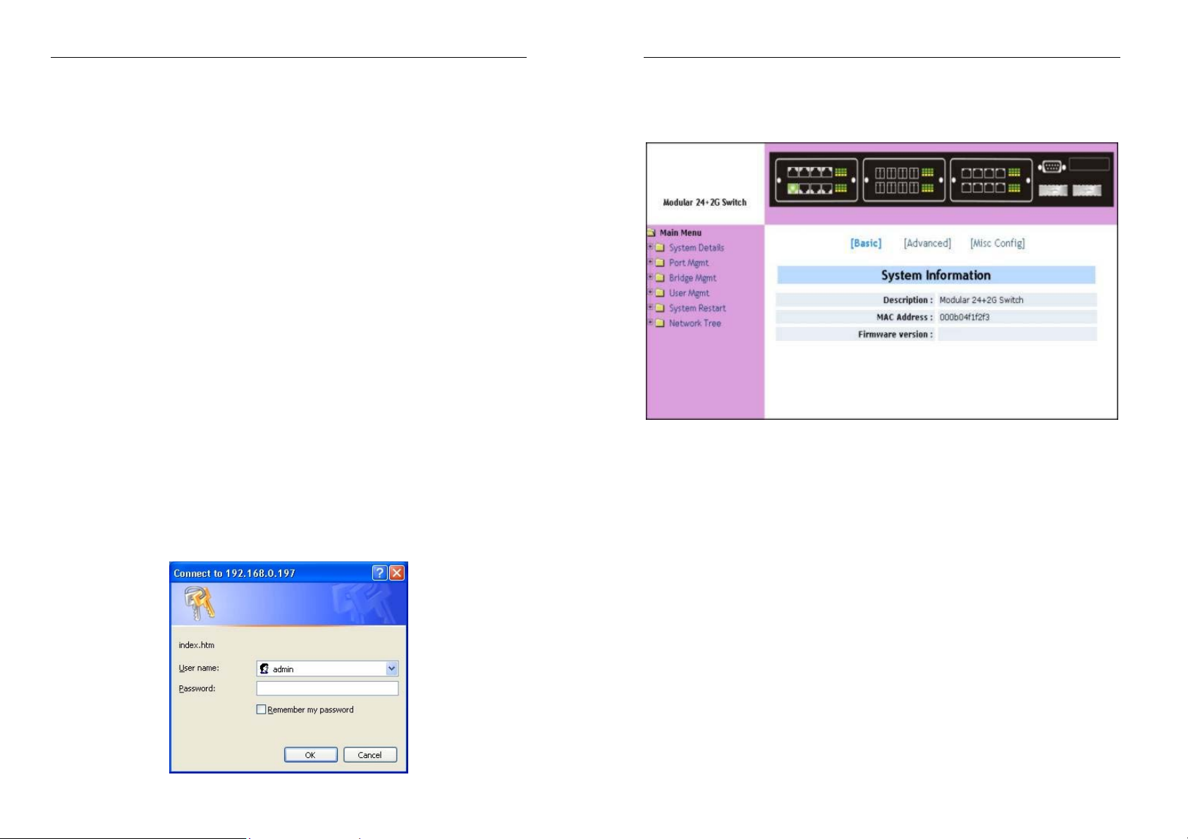
2. To access the Switch, open a web browser and key in the Switch’s
IP address. Enter username and password (default is no password)
and click on the <OK> button.
mode to secure a direct connection and to modify them.
2-1. Web Management Home Overview
1. This is the Home Page.
Basics
Description: Display the name of device type.
MAC Address:
Firmware Version: Display the Switch’s firmware version.
The unique hardware address assigned by
manufacturer (default)
5
6
Modularized 24+2G Switch
Modularized 24+2G Switch
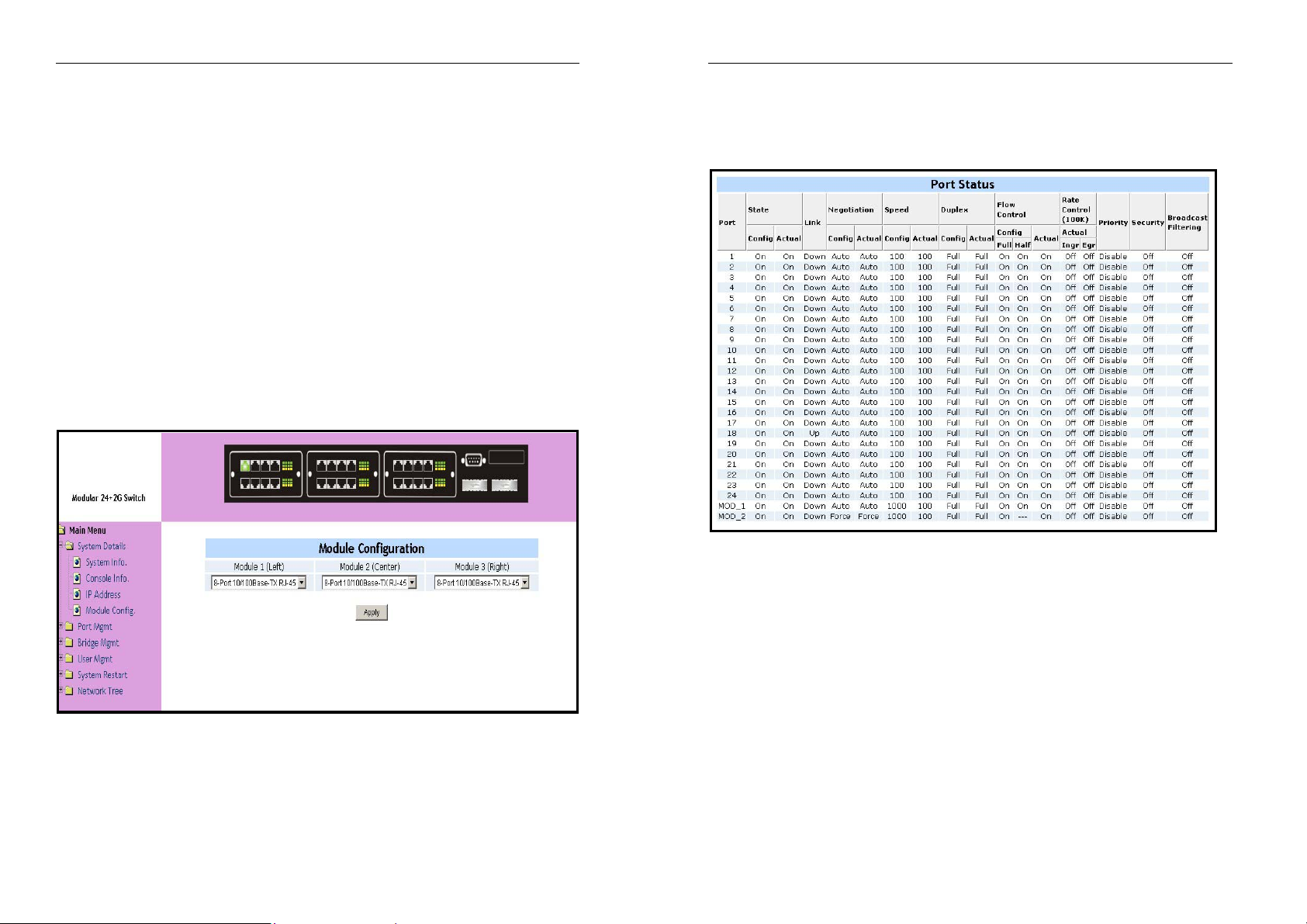
2-2. Module Type Configuration
The switch is modularized. In addition to two GBIC ports, there are three
modules selectable for your needs. For the different type modules, some
module/port settings maybe need to be reconfigured. You can configure
the module type by this function. The system can also configure all the
port settings of the module to the pre-defined values for you. If some of
the detail settings of each port do not meet your needs, you can change
them on a port-by-port basis from the Port Controls Page. The default
module type is 8-port 10/100 Base-TX RJ-45.
Available module types:
1. No Module
2. 8-Port 10/100 Base-TX RJ-45
3. 4-Port 100 Base-FX ST/SC
4. 8-Port 100 Base-FX LC
5. 8-Port 100 Base-FX MT-RJ
6. 8-Port 100 Base-FX BiDi
Warning: The modules are not hot swappable. You must
•
turn off the power before you change the modules. Failure
to do so may result in damage to the Switch.
2-3. Port status
This page can see every port status that depended on user setting and
the negotiation result.
1. State: Display port statuses disable or enable. “unlink” will be
treated as “off ”.
2. Link Status:
3. Auto-Negotiation:
auto/force/NWay.
4. Speed status:
port 1- 24 are 10/100Mbps, Port 25-26 are 10/100/1000Mbps
(depending on the modular card used).
5. Duplex status:
6. Flow Control:
Full: Display the flow control status is enable or disable in full mode.
Down is “No Link”, UP is “Link”.
Display the auto-negotiation mode:
Display 1000Mbps or 100Mbps or 10Mbps speed,
Display full duplex or half-duplex mode.
7
8
Modularized 24+2G Switch
Half: Display the backpressure is enable or disable in half mode.
7. Rate Control:
Ingr: Display the port effective ingress rate of user setting.
Egr: Display the port effective egress rate of user setting.
8. Priority:
disable.
9. Port Security:
10. Config: Display the state of user setting.
11. Atual: Display the negotiated result.
Display the rate control setting.
Display the port static priority status is High or Low or
Display the port security is enable or disable.
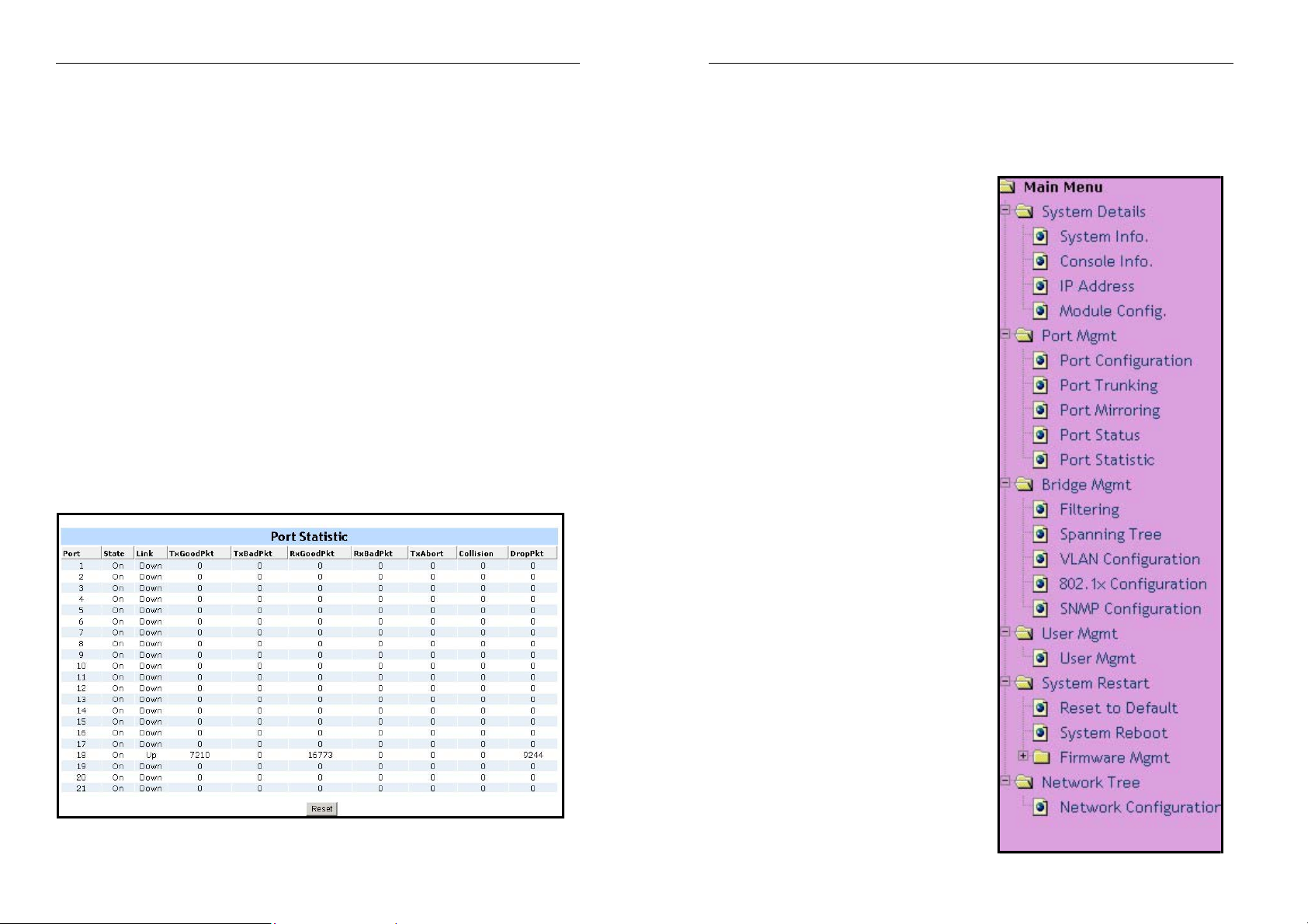
2-4. Port Statistics
Port statistics provide a summary of the current switch’s status, including
on/off state, link status, good or bad packets transmitting and receiving,
aborted packets, collisions and dropped packets.
Modularized 24+2G Switch
2-5. Administrator
There are many management functions that could be accessed via the
web browser. The main menu system lists all the functions. Simply click in
each item to go to the appropriate page.
9
10
Modularized 24+2G Switch
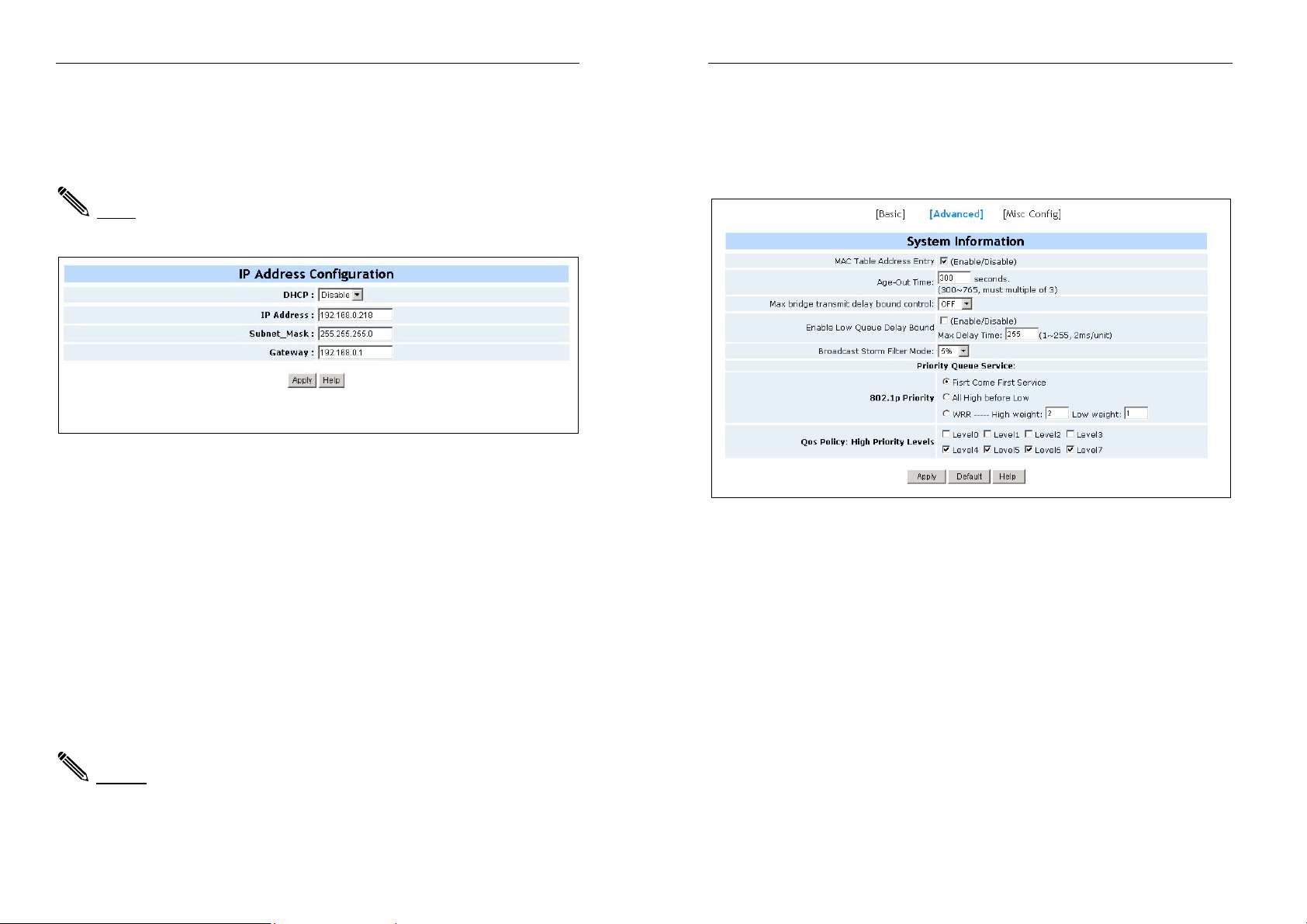
2-5-1. IP Address
1. The user can manually configure the IP Settings. Simply click on the
IP address field and enter the address, then click the apply button to
change the address.
Note: The user must reset/restart the Switch in order to use the new
IP address setting.
2-5-2. Advanced
Miscellaneous Setting:
MAC Address Age-out Time: Type the number of seconds that an
inactive MAC address remains in the switch's address table. The valid
range is 300~765 seconds. The default is 300 seconds.
Max bridge transmit delay bound control: Limit the packets queuing
time in the Switch. If enable, the packets queued exceed this time will be
dropped. This valid value are 1 sec, 2 sec, 4 sec and off.
Enable Low Queue Delay Bound: Limit the low priority packets queuing
time in Switch. If the low priority packets stay in Switch exceed the Max
Delay Time, it will be sent. The valid range is 1~255 ms.
NOTE: Make sure that “Max bridge transit delay bound control” is
enabled before activating the Delay Bound.
Modularized 24+2G Switch
Broadcast Storm Filter: To configure broadcast storm control, enable it
and set the upper threshold for individual ports. The threshold is the
percentage of the port's total bandwidth used by broadcast traffic. When
broadcast traffic for a port rises above this threshold, broadcast storm
control will activate. The valid threshold values are 5%, 10%, 15%, 20%,
25% and OFF.
Priority Queue Service settings:
First Come First Service (FCFS): The sequence of packets sent
depends on the order they arrive.
All High before Low (AHBL): The high priority packets are sent before
low priority packets.
Weighted Round Robin (WRR): Select the preferred ratio of high and
low priority packets sent by the switch in its priority queue. These options
represent the number of high priority packets sent before one low priority
packet is sent. For example, 5 High: 2 Low, means that the Switch sends
5 high priority packets before sending 2 low priority packet.
QoS Policy - Priority Levels:
designated high or low priority.
Collisions Retry Forever: Disable – In half-duplex, if collision occurs,
0~7 QoS levels can be assigned to
11
12
Modularized 24+2G Switch
the Switch will retry send 48 times and before dropping the frame.
Enable – In half-duplex, if collision occurs, the Switch will retry to send
frames indefinitely.
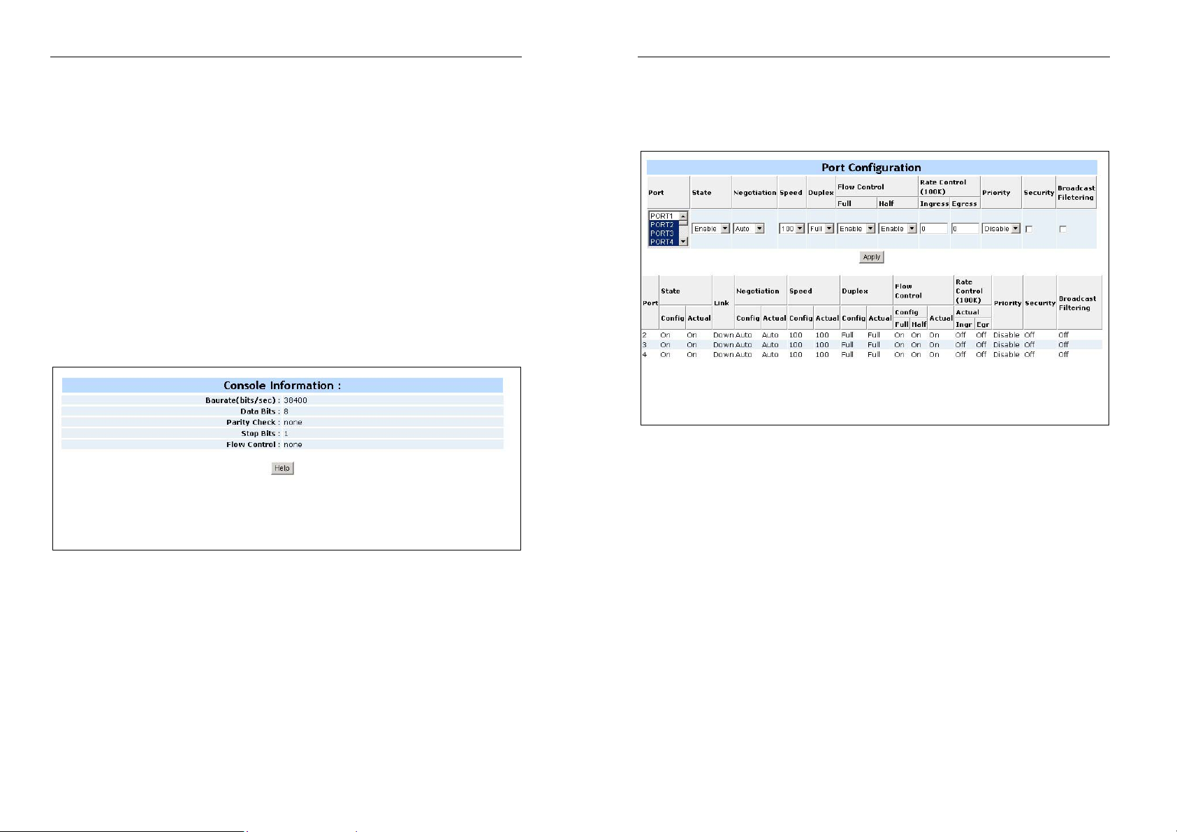
2-5-3. Console Port Information
1. Console is a standard UART interface to communicate with the
Serial Port. The user can launch windows HyperTerminal program
to link with the switch. See section three for details
Bits per seconds: 38400
Data bits: 8
Parity: none
Stop Bits: 1
Flow control: none
Modularized 24+2G Switch
2-5-4. Port Controls
Use this page to change the status of each port.
1. State: User can disable or enable this port control.
2. Auto-Negotiation: User can set auto-negotiation modes:
Force - specify the speed/duplex on this port with auto-negotiation
13
enable.
Auto NWay – for the Switch to automatically determine the highest
speed and duplex mode possible
3. Speed: User can set 100Mbps or 10Mbps speed on Port1~Port24.
User can set 1000Mbps, 100Mbps or 10Mbps speed on
Port25~Port26 (depending on module card specifications).
4. Duplex: User can set full duplex or half-duplex mode for each port.
5. Flows control:
Full: User can set full - flow control function (pause).
Half: User can set half – flow control (backpressure).
14
Modularized 24+2G Switch
6. Rate Control: port1 ~ port 24, supports by-port ingress and egress
rate control. For example, assume port 1 is 10Mbps, users can set its
effective egress rate to 1Mbps, ingress rate is 500Kbps. The Switch
will perform flow control or backpressure to confine the ingress rate to
meet the specified rate.
Ingress: Type the port effective ingress rate. The valid range is 0 ~
1000. The unit is 100K
0: disable rate control.
1 ~ 1000: valid rate value
Egress: Type the port effective egress rate. The valid range is
0~1000. The unit is 100K.
0: disable rate control.
1 ~ 1000: valid rate value.
7. Priority:
This static priority based on port, if you set the port to high
priority, the priority of incoming frames to this port will always be high
8. Port Security: A port in security mode will be “locked” without
permission of address learning. Only the incoming packets with
SMAC already existing in the address table can be forwarded . User
can disable the port from learning any new MAC addresses, then use
the static MAC addresses screen to define a list of MAC addresses
that can use the secure port. Enter the settings, then click Apply to set
the Switch with information provided on this page.
2-5-5. Trunking
The Link Aggregation Control Protocol (LACP) provides a standardized
means for exchanging information between Partner Systems on a link to
allow their Link Aggregation Control instances to reach agreement on the
identity of the Link Aggregation Group to which the link belongs. Move the
link to that Aggregation Group and enable its transmission and reception
functions in an orderly manner.
Link aggregation lets you group up to eight consecutive ports into a single
dedicated connection. This feature can expand bandwidth to a device on
the network. LACP operation requires full duplex mode, more detail
information refers to IEEE 802.3ad.
Modularized 24+2G Switch
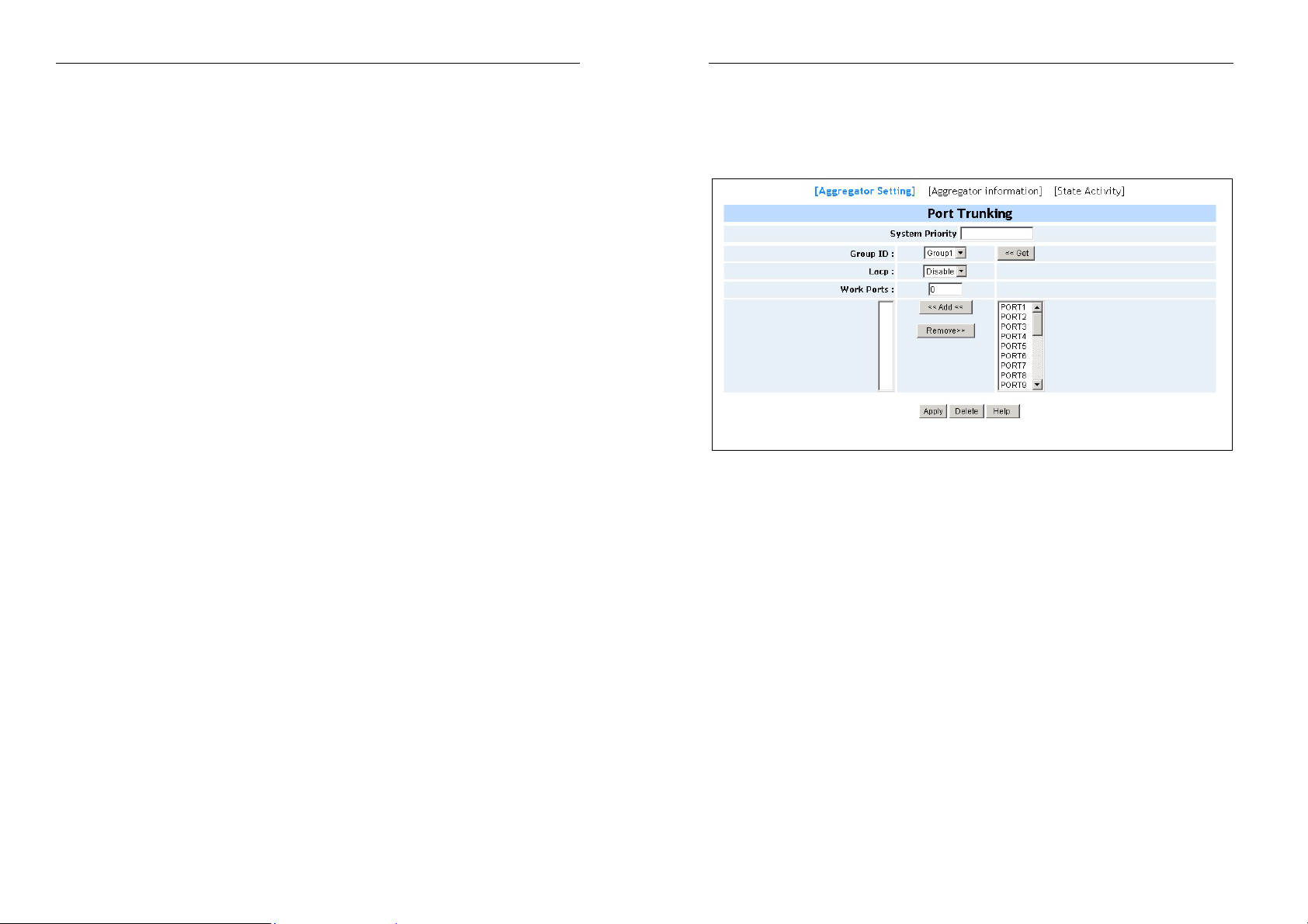
2-5-5-1. Aggregator Setting
System Priority: A value used to identify the active LACP. The Switch
with the lowest value has the highest priority and is selected as the active
LACP.
1. Group ID: There are seven trunk groups to provide configures.
Choose the "group id" and click "Get".
2. LACP:
If enable, the group is LACP static trunking group. If disable,
the group is local static trunking group. All ports support LACP
dynamic trunking group. If connecting to the device that also supports
LACP, the LACP dynamic trunking group will be created
automatically.
3. Work ports: Allow max. four ports can be aggregated at the same
time. If LACP static trunking group, the exceed ports are standby and
able to aggregate if work ports fail. If local static trunking group, the
number must be the same as the group member ports.
4. Select the ports to join the trunking group. Allow max. four ports can
be aggregated at the same time.
5. If LACP enable, you can configure LACP Active/Passive status in
each port on State Activity page.
6.
Click Apply.
15
16
Modularized 24+2G Switch
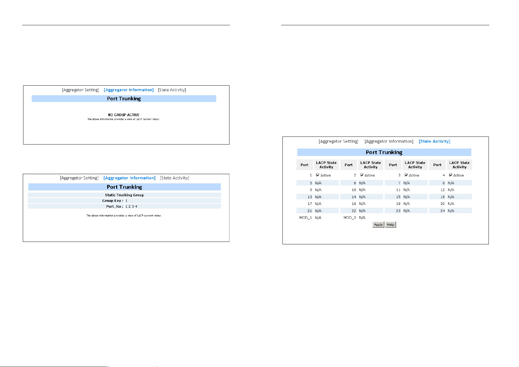
2-5-5-2. Aggregator Information
When setting LACP aggregator, you can view related information as
follows.
1. This page provides LACP current status. In this case, NO GROUP
ACTIVE, since LACP is not enabled.
2. This page displays Static Trunking groups.
Modularized 24+2G Switch
2-5-5-3. State Activity
Active (select): The port automatically sends LACP protocol packets.
Passive (no select): The port does not automatically send LACP protocol
packets, and respond only if it receives LACP protocol packets from
another networking device.
1. A link having either two active LACP ports or one active port can
perform dynamic LACP trunking. A link has two passive LACP ports
will not perform dynamic LACP trunking because both ports are
waiting for LACP protocol packet from another networking device.
2. If you are active LACP’s actor, when you select trunking port, the
active status will be created automatically.
17
18

2-5-6. Filter Database
2-5-6-1. IGMP Snooping
Modularized 24+2G Switch
Modularized 24+2G Switch
2-5-6-2. Static MAC Address
When you add a static MAC address, it is stored in the Switch's address
table regardless of whether the device is physically connected to the
Switch. This saves the Switch from having to re-learn a device's MAC
address when the device is disconnected or powered-off, and is then
active on the network again.
The Switch supports IP multicast, you can enable IGMP protocol on web
management’s switch setting advanced page, then display the IGMP
snooping information in this page You can view different multicast group,
VID and member ports here. IP multicast addresses range from 224.0.0.0
to 239.255.255.255.
The Internet Group Management Protocol (IGMP) is an internal protocol
of the Internet Protocol (IP) suite. IP manages multicast traffic by using
switches, routers, and hosts that support IGMP. Enabling IGMP allows
the ports to detect IGMP queries and report packets and manage IP
multicast traffic through the Switch. IGMP have three fundamental types
of messages. See table below:
Message Description
Query A message sent from the querier (IGMP router or switch) asking for a
response from each host belonging to the multicast group.
Report A message sent by a host to the querier to indicate that the host wants
to be or is a member of a given group indicated in the report message.
Leave Group A message sent by a host to the querier to indicate that the host has
quit to be a member of a specific multicast group.
19
1. From the main menu, click administrator Filter Database Static MAC
Address.
2. In the MAC address box, enter the MAC address to and from which
the port should permanently forward traffic, regardless of the device’s
network activity.
3. In the Port Number box, enter a port number.
4. If tag-based (IEEE 802.1Q) VLANs are set up on the Switch, static
addresses are associated with individual VLANs. Type the VID
(tag-based VLANs) associated with the MAC address.
5. Click on the Add button.
20
Modularized 24+2G Switch
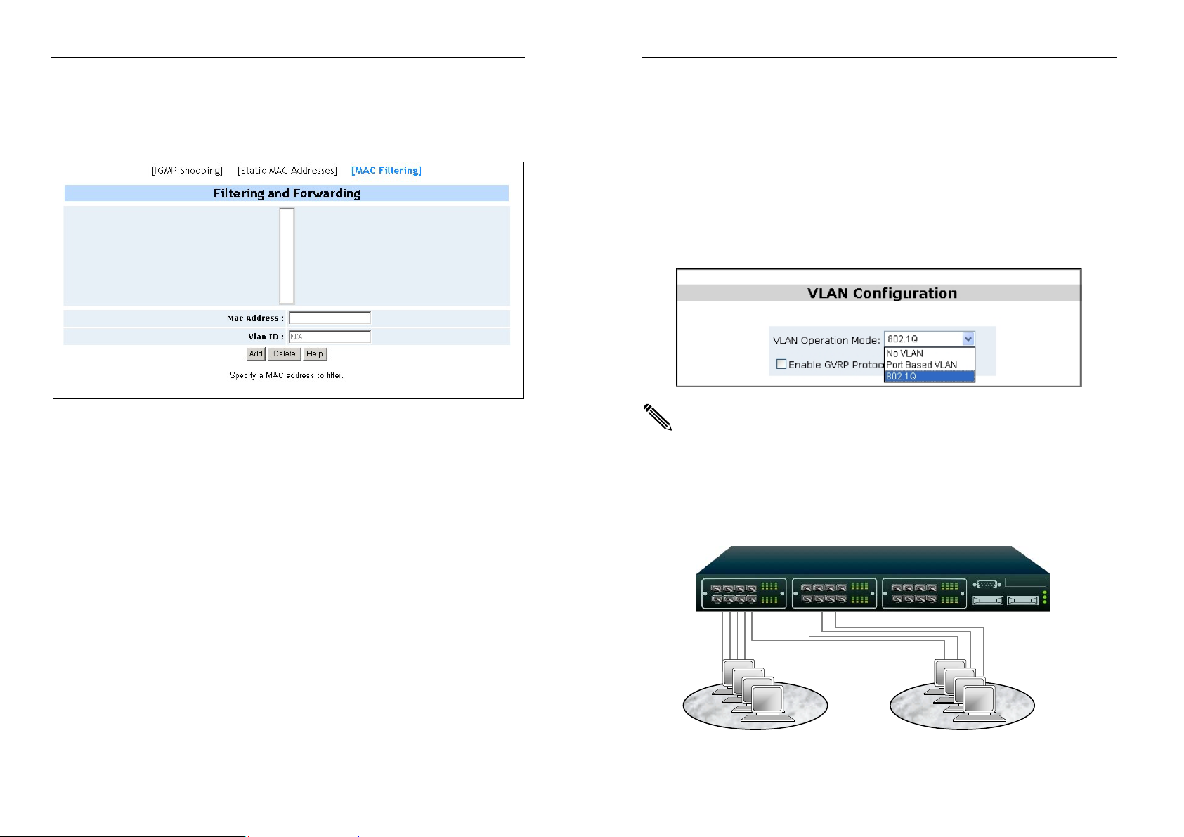
2-5-6-3. MAC Filtering
MAC address filtering allows the Switch to drop unwanted traffic. Traffic is
filtered based on the destination addresses.
Modularized 24+2G Switch
2-5-7. VLAN Configuration
A Virtual LAN (VLAN) is a logical network grouping that limits the
broadcast domain. It allows you to isolate network traffic so only members
of the VLAN receive traffic from the same VLAN members. Basically,
creating a VLAN in a switch is logically equivalent of reconnecting a group
of network devices to another Layer 2 switch. However, all the network
devices are still plug into the same switch physically. The Switch supports
port-based, 802.1Q (tagged-based) and protocol-based VLAN in web
management page. In the default configuration, VLAN support is disabled.
There are a few configuration examples in Appendix B for your reference.
1. In the MAC Address box, enter the MAC addresses that are to be
filtered.
2. If tag-based (802.1Q) VLAN are set up on the Switch, in the VLAN ID
box type the VID associated with the MAC address.
3. Click the on Add button.
4. Choose the MAC address that you want to delete and then click on
the Delete button
.
21
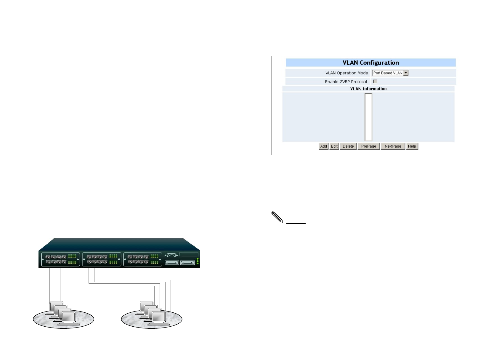
NOTE: Change VLAN mode for every time, you have to reboot the
Switch for valid value.
Support Port-based VLAN
Packets can go among only members of the same VLAN group. Note all
unselected ports are treated as belonging to another single VLAN. If the
port-based VLAN is enabled, the VLAN-tagging is ignored.
GROUP 1
SALES
GROUP 2
R&D
22
Modularized 24+2G Switch
Support Tag-based VLAN (IEEE 802.1Q VLAN)
Tagged-based VLAN is an IEEE 802.1Q specification standard.
Therefore, it is possible to create a VLAN across devices from different
switch venders. IEEE 802.1Q VLAN uses a technique to insert a “tag” into
the Ethernet frames. Tags contain a VLAN Identifier (VID) that indicates
the VLAN numbers.
Support Protocol-based VLAN
In order for an end station to send packets to different VLANs, it has to
either:
a. Be capable of tagging packets it sends with VLAN tags, OR
b. Be attached to a VLAN-aware bridge that is capable of
classifying and tagging the packet with different VLAN ID based
on not only default PVID but also other information about the
packet, such as the protocol.
The feature can be applied for accommodating devices that you want to
participate in the VLAN, but don’t support tagging. Therefore, the system
can add VAN tags to untagged frames which are based on PVID or on
different protocols.
The Switch will support protocol-based VLAN classification by means of
both built-in knowledge of layer 2 packet formats used by selected
popular protocols, such as Novell IPX and AppleTalk’s EtherTalk, and
some degree of programmable protocol matching capability. A port can
join more than one different protocol VLANs, but a port can’t apply a
same protocol twice for the VLAN configuration purpose. Otherwise you
will see the error message: “Save fail for ethertype conflict” when trying to
configure VLANs.
VID=2
VID=3
R&D
SALES
23
Modularized 24+2G Switch
2-5-7-1. Port Based VLAN
1. Click Add to create a new VLAN group.
2. Enter the VLAN name, group ID and select the members for the new
VLAN.
3. Click Apply.
4. If there are many groups that over the limit of one page, you can click
the “NextPage” to view other VLAN groups.
NOTE: If the trunk groups exist, they are displayed as: TRK1,
TRK2, …, in select menu of ports, and you can configure it to be the
member of the VLAN or not.
24
Modularized 24+2G Switch
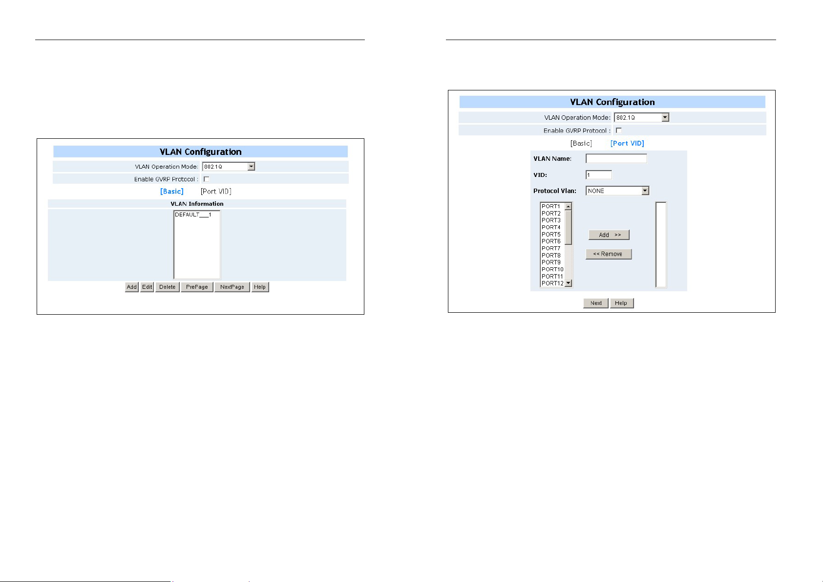
2-5-7-2. 802.1Q VLAN
Use this page to create tag-based VLANs, and enable or disable GVRP
protocol. There are 256 VLAN groups provided in the Switch. Enable
802.1Q VLAN, all ports on the Switch belong to a default VLAN. Its VID is
1. The default VLAN cannot be deleted.
Modularized 24+2G Switch
Basic
Create a VLAN and add tagged member ports to it.
GVRP (GARP [Generic Attribute Registration Protocol] VLAN
Registration Protocol) GVRP allows automatic VLAN configuration
between the Switch and nodes. If the Switch is connected to a device with
GVRP enabled, you can send a GVRP request using the VID of a VLAN
defined on the Switch. The Switch will automatically add that device to the
existing VLAN.
25
The above screen is the Main Tag-based VLAN page
1. From the main menu, click administrator VLAN configuration,
click Add then you will see the page as follow.
2. Type a name for the new VLAN.
3. Type a VID number (between 2-4094). The default is 1 (In total,
there are 255 VLANs that can be configured).
4. Choose the protocol type. If you are not applying protocol VLAN,
you must set the value to “NONE”. You can’t set a port to join
more than one VLANs/VIDs with a same protocol.
5. From the Available ports box, select ports to add to the switch
and click “Add >>”. If the trunk groups exist, you can see
displayed as: TRK1, TRK2, …, …, and you can configure it to bet
a member of the VLAN or not.
6. Click Next. Then you can view the page as follow.
26
Modularized 24+2G Switch
Modularized 24+2G Switch
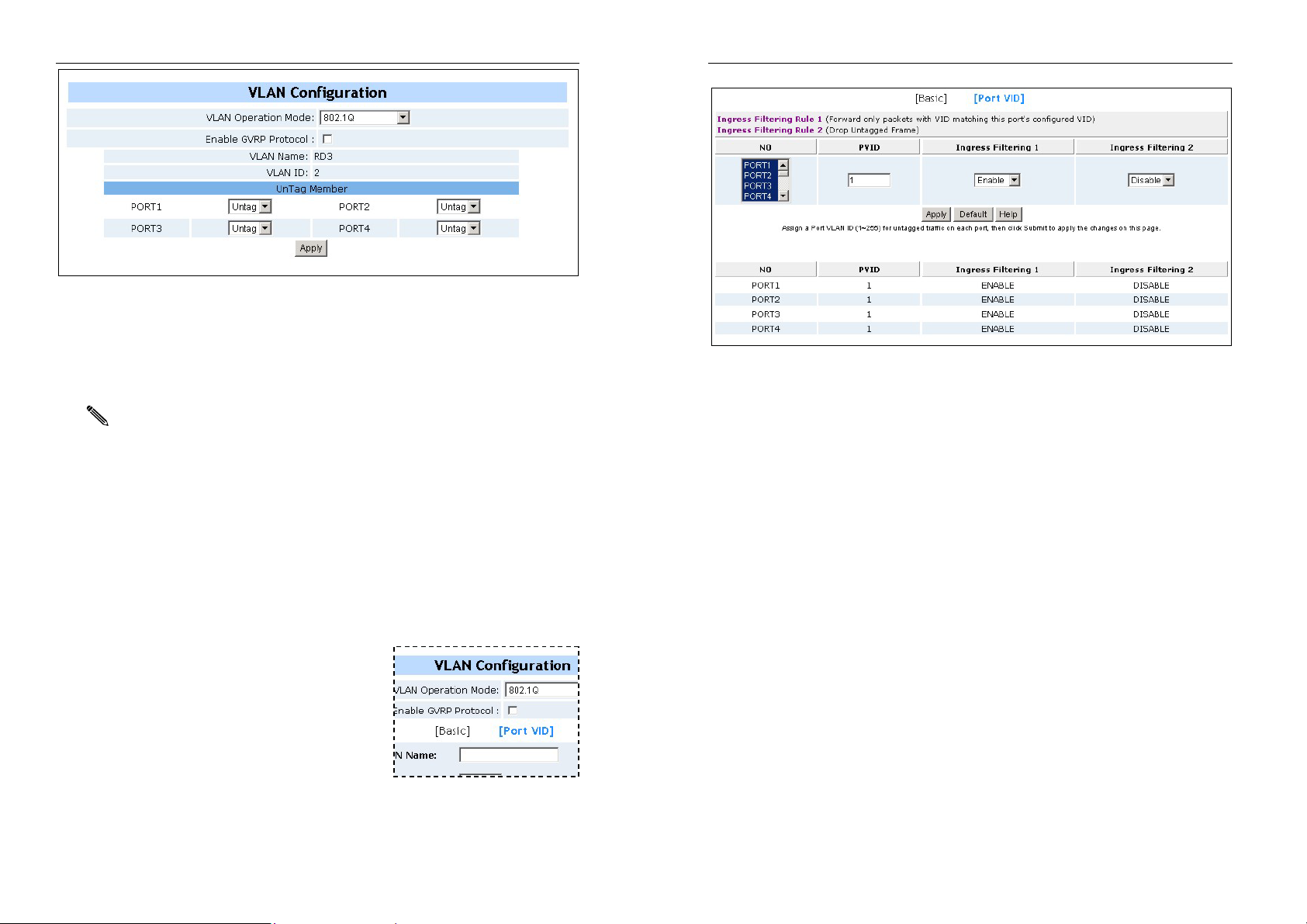
7. After adding ports to the VLAN, you use the above page to set the
outgoing frames as VLAN-tagged frames or not. The default is
‘Untag’. Using the dropdown box, select ‘Tag’ or ‘Untag’ and click
Apply.
Note: Unless you are sure the network has no tag-unaware devices, you should leave the
default setting of the outgoing frames to “Untag”.
Tag: Outgoing frames with VLAN-tagging.
Untag: Outgoing frames without VLAN-tagging.
Configure port VID settings
From the main tag-based (IEEE 802.1Q) VLAN page, click Port VID
Settings. Configure port VID settings
From the Main Tag-based VLAN page, click
[Port VID] (shown on the insert to the right) to
enter the Port VID Settings menu.
Port VID (PVID)
Set the port VLAN ID that will be assigned to untagged traffic on a given
port. This feature is useful for accommodating devices that you want to
participate in the VLAN but that don’t support tagging. Each port allows
user to set one PVID, the range is 1~4095, default PVID is 1.
Ports may share a same PVID, but all the PVIDs of the ports on the
switch must belong to the same 256 number group segment. (For
example: 1~255, 256~511,…3840~4095). This is in order to allow for
faster Ingress processing of frames. The PVID will be used for VLAN ID
tagging to untagged frames.
Note also that the PVID must be the same as the member VLAN group
IDs that the port belongs to, else the untagged traffic will be dropped.
This is because the port can’t transmit a frame with a VLAN Group ID it
doesn’t belong to. If a port also joins a protocol VLAN, the switch will
apply the protocol VLAN ID to untagged frames first. If the frame doesn’t
meet one of the protocols the port has defined, then the PVID will be
applied for this frame.
Ingress Filtering
Ingress filtering lets frames belonging to a specific VLAN to be forwarded.
The Switch has two ingress filtering rule as follows:
27
28
Modularized 24+2G Switch
Rule 1: Forward only packets with VID matching this port's configured
VID. The default is “Enable”. By default, only the packets with
VID matching this port’s configured VID can pass the port.
Rule 2: Drop Untagged Frame. The default is “Disable”. By default,
untagged packets can pass the port.
2-5-8. Spanning Tree
The Spanning Tree Protocol (STP) is a standardized method (IEEE 802.1D) for
avoiding loops in switched networks. When STP is enabled, it ensures that only
one path at a time is active between any two nodes on the network. You can
enable Spanning Tree Protocol on web management’s switch setting advanced
item, select enable Spanning Tree protocol. We recommend that you enable STP
on all switches to ensure that only a single active path on the network exists.
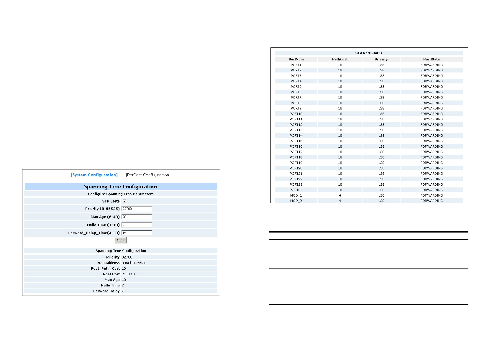
1. From the Spanning Tree Configuration Menu (shown below), you can
create a new value for the STP parameter, then click the Apply button to set
it. You can view spanning tree information the Root Bridge from the same
screen.
Modularized 24+2G Switch
2. You can view spanning tree status about the Switch from the
following screen.
Parameter Description
Priority You can change priority value, A value used to
identify the root bridge. The bridge with the lowest
value has the highest priority and is selected as
the root. Enter a value from 1 through to 65535.
Max Age You can change Max. Age value, the number of
seconds a bridge waits without receiving Spanning
Tree Protocol configuration messages before
attempting a reconfiguration. Enter a time in
seconds from 6 through to 40.
29
30

Modularized 24+2G Switch
Modularized 24+2G Switch
Hello Time You can change the Hello time value, the number
of seconds between the transmissions of
Spanning Tree Protocol configuration messages.
Enter a time in seconds from 1 through to 10.
Forward Delay time
3. From the Spanning Tree Configuration Menu, click PerPort Configuration
to configure STP parameters on each port, click on the Apply button to set
it.
You can change forward delay time, The number
of seconds a port waits before changing from its
Spanning Tree Protocol learning and listening
states to the forwarding status. Enter a time in
seconds from 4 through to 30.
Path Cost Specifies the path cost of the port. The Switch uses this
to determine which port are the forwarding ports. The
lowest numbers assigned are the forwarding ports. The
range is between 1 and 65535 and the default value
base on IEEE802.1D are:
10Mb/s = 50-600 100Mb/s = 10-60 1000Mb/s = 3-10
2-5-9. Port Mirroring
Port Mirroring is a method to monitor traffic in switched networks. Traffic
through ports can be monitored by one specific port. That is, traffic going in or
out monitored ports will be duplicated to a mirror port.
Parameter Description
Port Priority You can make the port more or less likely in becoming
the root port. The range is between 0-255. Its default
setting is 128. The lowest number has the highest
priority.
31
Roving Analysis State: Roving analysis is the mirroring of Fast Ethernet
port traffic to another port of the same media type within a system that
has an RMON probe or analyzer attached. This port allows external
RMON probes (network analyzers) to monitor traffic on any switched
segment.
You can monitor a designated roving analysis port to: Analyze traffic loads on
each segment so that you can continually optimize your network loads by
moving network segments, or troubleshoot switched network problems (for
example, to find out why a particular segment has so much traffic)
32
Modularized 24+2G Switch
Analysis Port: You can have as many as 16 network analyzers
connected to a system. For more accurate analysis, attach the analyzer
to a dedicated port instead of through a repeater. When the analyzer port
is set, it cannot receive or transmit any other data. Instead, it receives
only the data from the ports to be monitored.
Monitor Port: The ports you want to monitor. All monitor port traffic will be
copied to mirror port. You can select max 25 monitor ports in the switch. User
can choose which port that they want to monitor in only one mirror mode.
For each port 1-24 you wish to monitor, click the check box next that port.
When finished, click Apply
2-5-10. SNMP
Any Network Management platform running the simple Network
Management Protocol (SNMP) can manage the switch, provided the
Management Information Base (MIB) is installed correctly on the
management station. The SNMP is a Protocol that governs the transfer of
information between management station and agent.
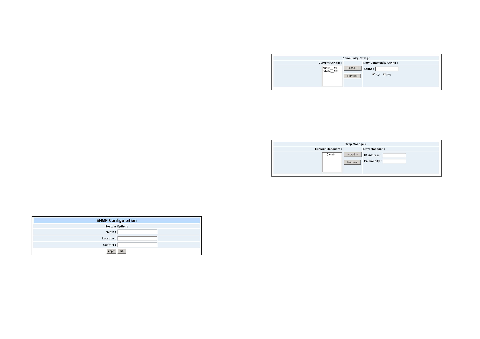
1. System Options: Use this page to define management stations as trap
managers and to enter SNMP community strings. User can also define
a name, location, and contact person for the switch. Fill in the system
options data, and then click Apply to update the changes on this page.
Name: Enter a name to be used for the switch.
Location: Enter the location of the switch.
Contact: Enter the name of a person or organization.
2. Community strings: serve as passwords and can be entered as one
of the following:
RO: Read only. Enables requests accompanied by this string to display
Modularized 24+2G Switch
MIB-object information.
RW
: Read write. Enables requests accompanied by this string to
display MIB-object information and to set MIB objects.
3. Trap Manager: The trap manager is a management station that receives
traps, the system alerts generated by the switch. If no trap manager is defined,
no traps are issued. Create a trap manager by entering the IP address of the
station and a community string the press “<<Add<<”.
2-5-11. Security Manager
Use this page, user can change web management user name and
password.
1. User name: Type the new user name.
2. Password: Type the new password.
3. Reconfirm password: Retype the new password.
4. Click Apply.
33
34

Modularized 24+2G Switch
2-5-12. TFTP Update Firmware
The following menu options provide some system control functions to
allow a user to update firmware and remote boot switch system:
1. Install TFTP Turbo98 and execution.
2. Copy firmware update version bin to TFTP Turbo98 directory.
3. In web management select administrator—TFTP update firmware.
4. Download new bin file then in web management press <update
firmware>.
5. After update finished, press <reboot> to restart switch.
Note: the address and file name in the above screen shot are just example
Modularized 24+2G Switch
2-5-13. Configuration Backup
2-5-13-1. TFTP Rsetore Configuration
Use this page to set TFTP server address. You can restore EEPROM
value from here, but you must put back image in TFTP server, Switch will
download back flash image.
Note: the address and file name in the above screen shot are just example
2-5-13-2. TFTP Backup Configuration
Use this page to set TFTP server ip address. You can save current
EEPROM value from here, then go to the TFTP restore configuration
page to restore the EEPROM value.
Note: the address and file name in the above screen shot are just example
35
36

Modularized 24+2G Switch
Modularized 24+2G Switch
2-5-14. Reboot
Reboot the Switch with a software reset.
2-5-15. Network Tree
The “web cluster” feature will search switch nodes connected to the local
network, and allows users to add/delete any network node(s) to/from the
network tree. So that users not only have a network view, but also access
or control switches or nodes from the local switch’s web interface. See
the following diagram..
3.
Console
1K Xmodem Update Firmware
The Switch provides a 1k Xmodem to update firmware via console. The
application only works in 38400bps mode. There are two cases where by
the 1K Xmodem is used:
A, User enters "1K Xmodem receiver mode" through pressing any key
within 3 seconds after system is powered on.
B, The system automatically enters "1K Xmodem receiver mode" if it
detects the firmware checksum fail while booting.
1. Start Xmodem receiver mode. Follow the screen cues by cliking any
key .
37
38

Modularized 24+2G Switch
2. By clicking on the connected button, you will see “CCCC…”displayed
on console. Select
Transfer -> Send File.
Modularized 24+2G Switch
4. Start download image file.
3. Select 1K Xmodem in the Protocol item, and specify the path where
the image file is to be sent. Then click on the Send button.
39
5. Finish download image - the switch system will update firmware
automatic. Update firmware ok - the switch will reboot.
40

Modularized 24+2G Switch
Modularized 24+2G Switch
4.
Console
Menu
Line
1. The Switch features a serial interface to manage and to monitor the
system. User can follow the Console Port Information provided by
web to use windows HyperTerminal program to link the Switch.
2. You can type user name and password to login. The default user
name is “admin”, with no default password.
4-1. Main Menu
There are six items on the Main Menu page. They are as follows:
Switch Static Configuration: Configure the Switch.
Protocol Related Configuration: Configure the protocol function.
Status and Counters: Show the status of the Switch.
Reboot Switch: Restart the system or reset Switch
to default configuration.
TFTP Update Firmware: Use tftp to download image.
Logout: Exit the menu line program.
<Control Key>
The control key provided in all menus as follow:
Tab: Move the cursor to next item.
Backspace: Move the cursor to previous item.
Enter: Select item.
Space: Toggle selectable items
41
42

Modularized 24+2G Switch
Modularized 24+2G Switch
4-2. Switch Static Configurations
You can press the key of Tab or Backspace to choose item, and press
Enter
key to select item
The following action menu line is provided within the configuration pages.
Actions->
<Quit>: Exit the current page and return to previous menu.
<Edit>:
<Save>: Save all configured values.
<Previous Page>:
<Next page>: Go to next page.
Configure items. When finished configurations, press
go back action menu line.
Return to previous page.
Ctrl+A
to
4-2-1. Port Configuration
This page allows the configuration of each port. Press <Space> key to
change the status of each item.
InRate (100K/unit): User can set input rate control. Each unit is 100K.
The valid range is 0~1000.
0: disable rate control.
1~1000: valid rate value.
OutRate (100K/unit): User can set output rate control. Each unit is 100K.
The valid range is 0~1000.
0: disable rate control.
1~1000: valid rate value.
Enabled: User can disable or enable each port. “Yes” means that the port
is enabled. “No” means the port is disabled.
Auto: User can set the auto negotiation mode.
Auto
NWay Force
Force
Spd/Dpx: User can set 100Mbps or 10Mbps speed on port 1~port 24, set
1000Mbps, 100Mbps or 10Mbps speed on port25~port26 (depending on
43
44
Modularized 24+2G Switch
the performance of the uplink module card), and set full duplex or
half-duplex modes.
Flow Control:
Full: User can enable or disable full flow control function (pause)
Half: User can enable or disable half flow control function
(back-pressure).
NOTE:
1. Selecting <Save> will only save the new configuration on the current
2. If the static trunk groups exist, you can see them after port 26 (e.g.
page.
TRK1, TRK2…), and they can be configured similarly to the items
above.
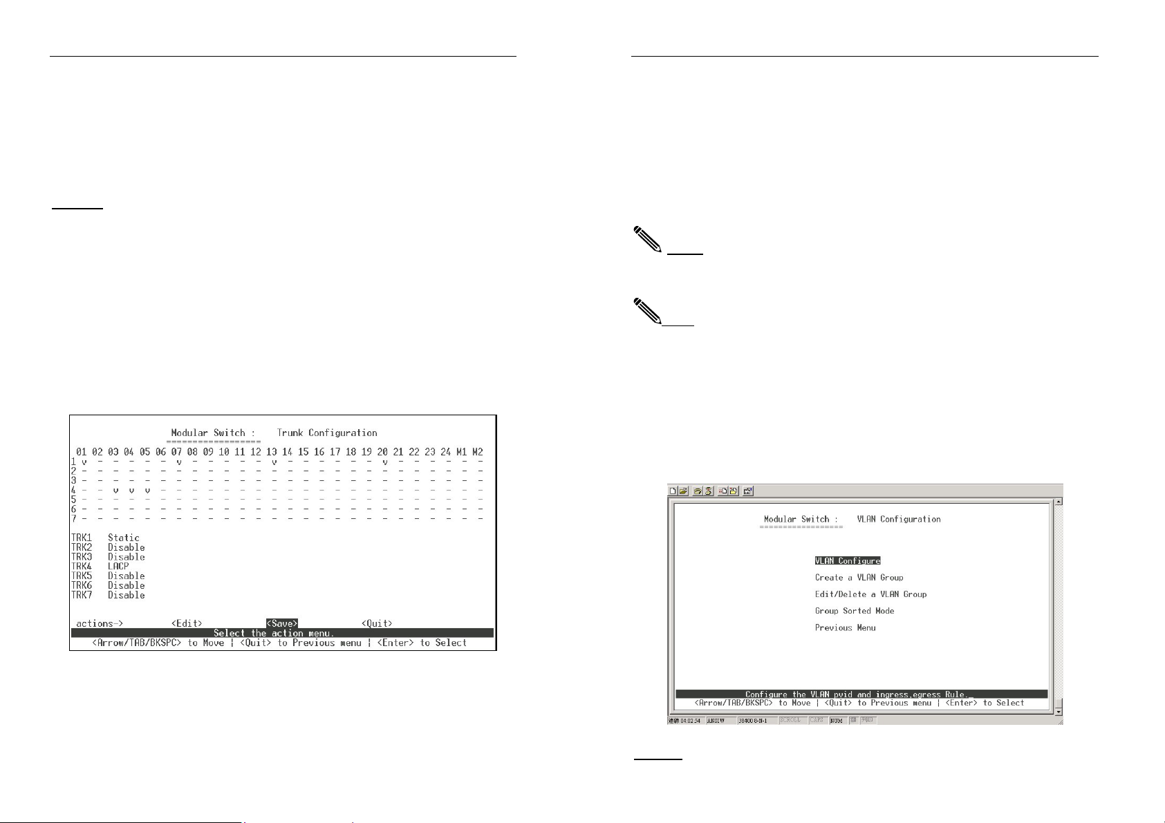
4-2-2. Trunk Configurations
Use this page to create a maximum of up to seven trunk groups. The user
can arbitrarily select up to four ports from port 1~port 26 to build a
trunking group.
Modularized 24+2G Switch
Below that are the “Static” or “LACP” settings the corresponding
trunk groups (TRK1~TRK7).
“Static” - the normal trunk.
“LACP” - trunking with Link Aggregation Control Protocol.
“Disable”, - the trunk group is deleted.
3. Press Ctrl+A to go back to the action menu line. Select <Save> to
save all configured values.
NOTE:All ports in the same static trunk group will be treated as single port. So when you
setting VLAN members and Port configuration they will be toggled on or off
simultaneously.
NOTE: If a VLAN Group exists, all of the members of static trunk group must be in same
VLAN Group.
4-2-3. VLAN Configuration
Use this page to set port-based VLAN or 802.1Q VLAN or to deactivate
the VLAN function. There are a few configuration examples in Appendix B
for your reference.
1. Select <Edit> on actions menu
2. The numbers running down the left hand side of the page represent
the trunk groups. Press the <space> key to configure the member
ports of each trunk group.
45
NOTE: Each time the VLANS are modified, the Switch must be restarted
46
Modularized 24+2G Switch
for the new configurations to take affect.
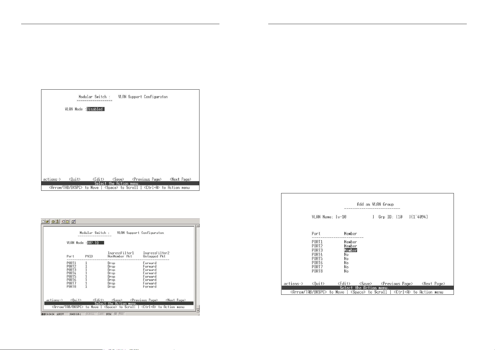
4-2-3-1. VLAN Configurations
There are three types to selected:
a. Disable
b. Port Based
c. 802.1Q
Default VLAN configuration is disable .
If 802.1Q VLAN are set, you can set PVID, ingress filtering 1 and ingress
filtering 2 on this page too.
Modularized 24+2G Switch
1. PVID (Port VID : 1~4095): Type the PVID. Each port allows user to
set one PVID, the range is 1~4095, default PVID is 1. Some ports can
share a same PVID. But in a same switch, all the PVIDs of the ports
of the switch must belong to a same 256 number segment, for
example 1~255, 256~511,…3840~4095.
NonMember Pkt:
2.
It matches the Ingress Filtering Rule 1 on web.
Either forward only packets with VID matching this port’s configured
VID, or to drop the frame when VID is not matching this port’s
configured VID. Press <Space> key to choose drop or forward. The
default is drop. It is the same as the filtering rule 1 is enabled on web.
3. UnTagged Pkt: It matches the Ingress Filtering Rule 2 on web.
Either drop or forward untagged frame. Press <Space> key to
choose drop or forward. The default is forward. It is the same as the
filtering rule 2 is enabled on web.
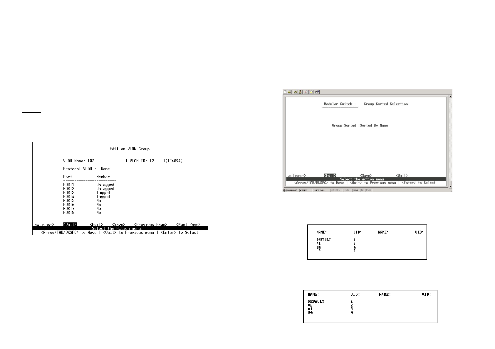
4-2-3-2. Create a VLAN Group
Create Port-Based VLAN
Creating a port-based VLAN and to add member/nonmember ports to it.
47
1. Select <Edit>.
48

Modularized 24+2G Switch
2. VLAN Name: Type a name for the new VLAN.
3. Grp ID: Type the VLAN group ID. The group ID range is 1~4094.
4. Member: Press <Space> key to choose VLAN member. There are
two types to selected:
d. Member: the port is a member of the current VLAN.
e. NO: the port is NOT a member of the current VLAN.
5. Press Ctrl+A to go back to the action menu line.
6. Select <Save> to save all configure values.
NOTE:
If the trunk groups exist, you can see it after port26 (e.g. TRK1, TRK2…), and if
desired, can chose to assign it is a member of the VLAN.
Create 802.1Q VLAN
Modularized 24+2G Switch
3. VLAN ID: Type a VID (between 2~4094). The default is 1. There are 256
VLAN groups provided for configuration. Each port can join more than one,
(up to 256) tagged VLAN groups.
4. Protocol VLAN: Press <Space> key to choose protocols type. If you are
not applying protocol VLAN, you must set the value to “None”. You can’t
set a port to join more than one VLANs/VIDs with a same protocol.
5. Member: Press <Space> key to choose VLAN member. There are three
types to select from:
a. UnTagged: this port is a member port of this VLAN group and
outgoing frames are NOT VLAN-Tagged frames.
b. Tagged: this port is a member port of this VLAN group and
outgoing frames are VLAN-Tagged frames.
c. NO: the port is NOT a member port of this VLAN group.
6. Press Ctrl+A to go back to the action menu line.
7. Select <Save> to save all configure values.
NOTE: If the trunk groups exist, you can see it after port26 (e.g. TRK1, TRK2…), and if
desired, can chose to assign it is a member of the VLAN.
4-2-3-3. Edit / Delete A VLAN Group
To create a 802.1Q VLAN and add tagged /untagged member ports to it, follow
the below procedure.
1. Select <Edit>.
2. VLAN Name: Type a name for the new VLAN.
49
Use this page to edit or delete a VLAN group.
50
Modularized 24+2G Switch
1. Select <Edit> or <Delete> item.
2. Choose the VLAN group that you want to edit or delete and then
press enter.
3. User can modify the protocol VLAN item and whether the member
port is tagged or un-tagged, and remove some member ports from an
existing VLAN group.
4. After editing the VLAN, press the <Save> key to save all configure
values.
NOTE:
1.When pressing
2.The VLAN Name and VLAN ID cannot be modified.
3.The default VLAN cannot be deleted.
<Enter>
once will complete deletion on delete mode.
Modularized 24+2G Switch
4-2-3-4. Groups Sort Mode
In this page, user can select VLAN group sort mode. The options are:
(1) sorted by name
(2) sorted by VID
In the Edit/Delete a VLAN group page, the following will be
displayed.
In the Edit/Delete a VLAN Group page, the result of the sort will be
displayed.
51
In the Edit/Delete a VLAN Group page, the result of sorting by VID is
diplayed.
52
Modularized 24+2G Switch
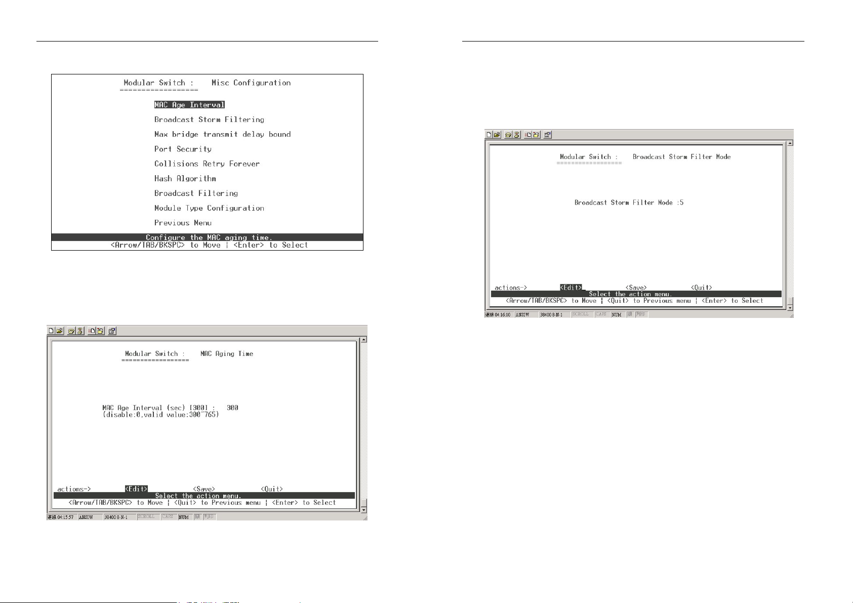
4-2-4.Misc Configuration
4-2-4-1. MAC Age Interval
Type the number of seconds that an inactive MAC address remains in the
Switch’s address table. The valid range is 300~765 seconds. The default
is 300 seconds.
Modularized 24+2G Switch
Use this page to configure broadcast storm control.
1. Select <Edit> to configure the broadcast storm filter mode.
2. Press <Space> key to choose the threshold value.
The valid threshold values are 5%, 10%,15%,20%,25% and NO.
4-2-4-3. Max Bridge Transmit Delay Bound
1. Max bridge transmit delay bound: Limit the packets queuing time in
the Switch. If enable, the packets queued that have exceed this time
frame will be drop. Press <Space> key to set the time. The valid
values are 1sec, 2secs, 4secs and off. The default is off.
2. Low Queue Delay Bound: Limits the low priority packets queuing
time in the Switch. When enabled, the low priority packets in the
Switch that have exceeded the Low Queue Max Delay Time it will be
sent. Press <Space> key to enable or disable this function.
4-2-4-2. Broadcast Storm Filtering
53
54

Modularized 24+2G Switch
Low Queue Max Delay Time:
3.
To set the time that low priority
packets are queued in the Switch. Default Max Delay Time is 255ms.
The valid range is 1~255 ms.
NOTE:
Make sure that the “Max bridge transit delay bound control” is
enabled before the Low Queue Delay Bound is enabled because the
former must be activated before the latter will work.
Modularized 24+2G Switch
4-2-4-4. Port Security
A port in security mode will be “locked” and does not permit address
learning. Only incoming packets with Static Media Access Control (SMAC)
already existing in the address table can be forwarded normally. The user
can disable the port from learning any new MAC addresses. Then use the
static MAC address screen to define a list of MAC addresses that can use
the secured port.
1. Select <Edit>.
2. Press Space key to choose enable / disable item.
3. Press
Ctrl+A
to go back action menu line.
4. Select <Save> to save all configure value.
5. You can press <Next Page> to configure port9 ~ port26, press
<Previous Page>
55
return to last page.
56

Modularized 24+2G Switch
Modularized 24+2G Switch
4-2-4-5. Collisions Retry Forever
Collisions Retry Forever:
Disabled – In half-duplex, if collision happens the Switch will retry to send
the frame 48 times before the frame is dropped.
Enabled – In half-duplex, if collision happens the Switch will retry to send
the frame indefinitely.
4-2-4-6. Hash Algorithm
CRC-hash/Direct-map Hash Algorithm.
4-2-4-7. Broadcast Filtering
In a regular wired LAN network, there is a lot of broadcasted
traffic. In order to filter the broadcast traffic, the user may disable
or enable Broadcast Filtering for each port.
57
58

Modularized 24+2G Switch
Modularized 24+2G Switch
4-2-4-8. Module Type Configuration
Selection physical Module type for help configuration switch .
Support module type:
1. No Module
2. 8-Port 10/100 Base-TX RJ-45
3. 4-Port 100 Base-FX ST/SC
4. 8-Port 100 Base-FX LC
5. 8-Port 100 Base-FX MT-RJ
6. 8-Port 100 Base-FX BiDi
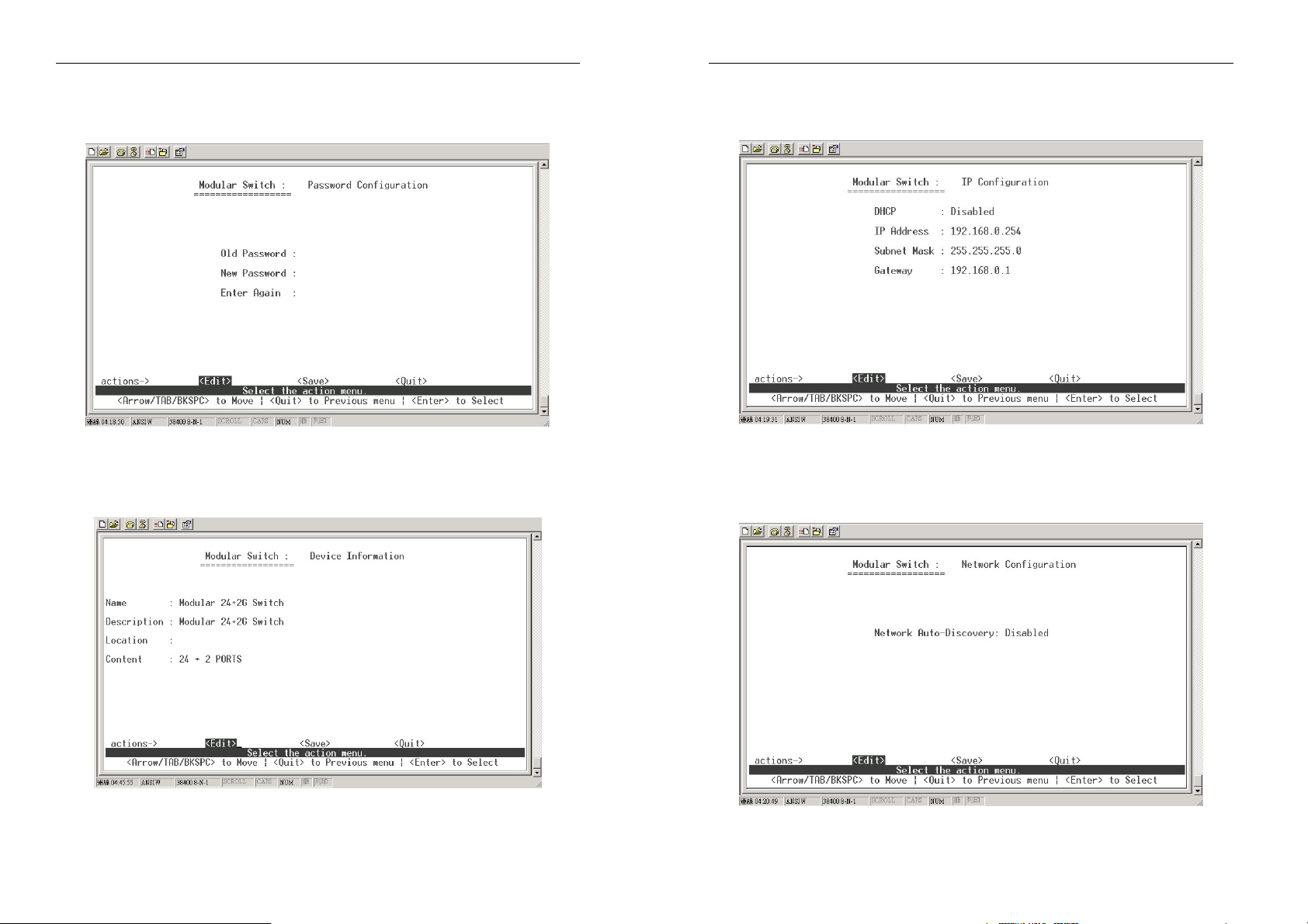
4-2-5. Administration Configuration
4-2-5-1. Change Username
Use this page to change web management user name.
Type the new user name, then select <Save> to change the username.
59
60
Modularized 24+2G Switch
4-2-5-2. Change Password
Use this page to change web management login password.
Modularized 24+2G Switch
4-2-5-4. IP Configuration
Use this page to configure the IP setting and fill in the new value.
4-2-5-3. Device Information
Use this page to configure the device information.
4-2-5-5. Network Configuration
Use this page to Enable/Disable Network Device Auto-Discovery feature
61
62

4-2-5-6. Network Device Configure
Configure and add static network device
Modularized 24+2G Switch
Modularized 24+2G Switch
4-2-6. Port Mirroring Configuration
The port mirroring is a method for monitor traffic in switched networks.
Traffic passing through ports can be monitored by one specific port. That
is the traffic going in or out of the monitored ports will be duplicated into a
separate monitoring port.
Press <Space> key to change configuration of each item.
1. Select
2. Sniffer Mode: Press <Space> key to select the sniffer mode. The
options are: Disable / Rx / Tx / Both.
3. Monitoring Port - sniffer port can be used to monitor all ports traffic.
Press <Space> key to select it.
Monitored Port -
4.
traffic will be copied to the sniffer port. You can select a maximum of
25 monitored ports in the Switch. The user can choose the ports to be
monitored in one sniffer mode. Press Space key to select the
member port, “V” is a member, “—“ isn’t a member.
5. Press Ctrl+A go back to the action menu line
6. Select
7. On the action menu line you can press <Next Page> to configure
port9 ~
NOTE: Only one sniffer mode can be activated at a time.
<Edit>
<Save>
port26, select
the ports you want to monitor. All monitored port
to save all configured values.
<Previous Page>
return to last page.
63
64

Modularized 24+2G Switch
4-2-7. Priority Configuration
4-2-7-1. Port Static Priority
The static priority is port-based. When a port is assigned with a high
priority, incoming frames from this port always have a high priority.
Modularized 24+2G Switch
4-2-7-2. 802.1P Priority Configuration
There are 0~7 priority queue levels that can be assigned.
1. Select <Edit>
2. Press <Space> key to select the priority level mapping from low to
high queue.
3. High/Low Queue Service Ratio H:L - User can select the ratio of
high priority packets and low priority packets.
4. Press Ctrl+A go back action menu line.
5. Selcet <Save> to save all configure value.
65
66

4-2-8. MAC Address Configuration
Modularized 24+2G Switch
Modularized 24+2G Switch
Add static MAC address
•
1. Select <Add> and then <Edit> to add static MAC address.
2. MAC Address - Enter the MAC address to the port that should
permanently forward traffic regardless of the Switch’s network
activity.
3. Port num - press <Space> key to select the port number.
4. Vlan ID - If they are tag-based (802.1Q), VLANs are set up on the
Switch. Static addresses are associated with individual VLANs. Type
the VID to associated with the MAC address.
5. Press Ctrl+A to go back to the action menu line, and then select
<Save> to save all configured values.
4-2-8-1. Static MAC Address
When you add a static MAC address, it remains in the Switch's address
table regardless of whether the device is physically connected to the
Switch. This saves the Switch from having to re-learn a device's MAC
address when the Switch is disconnected or powered-off and becomes
active on the network again.
In this page the user can add / modify / delete a static MAC address.
Edit static MAC address
•
1. Press <Edit> key.
2. Choose the MAC address that you want to modify and then press
Enter.
67
68

Modularized 24+2G Switch
Modularized 24+2G Switch
3. Press
<Edit>
key to modify all the items.
4. Press Ctrl+A to go back to the action menu line, and then select
<Save> to save all configured values.
Delete static MAC address
1. Press <Delete> key.
2. Choose the MAC address that you want to delete and then press
enter.
3. By pressing <Enter> once will complete the deletion.
69
70
Modularized 24+2G Switch
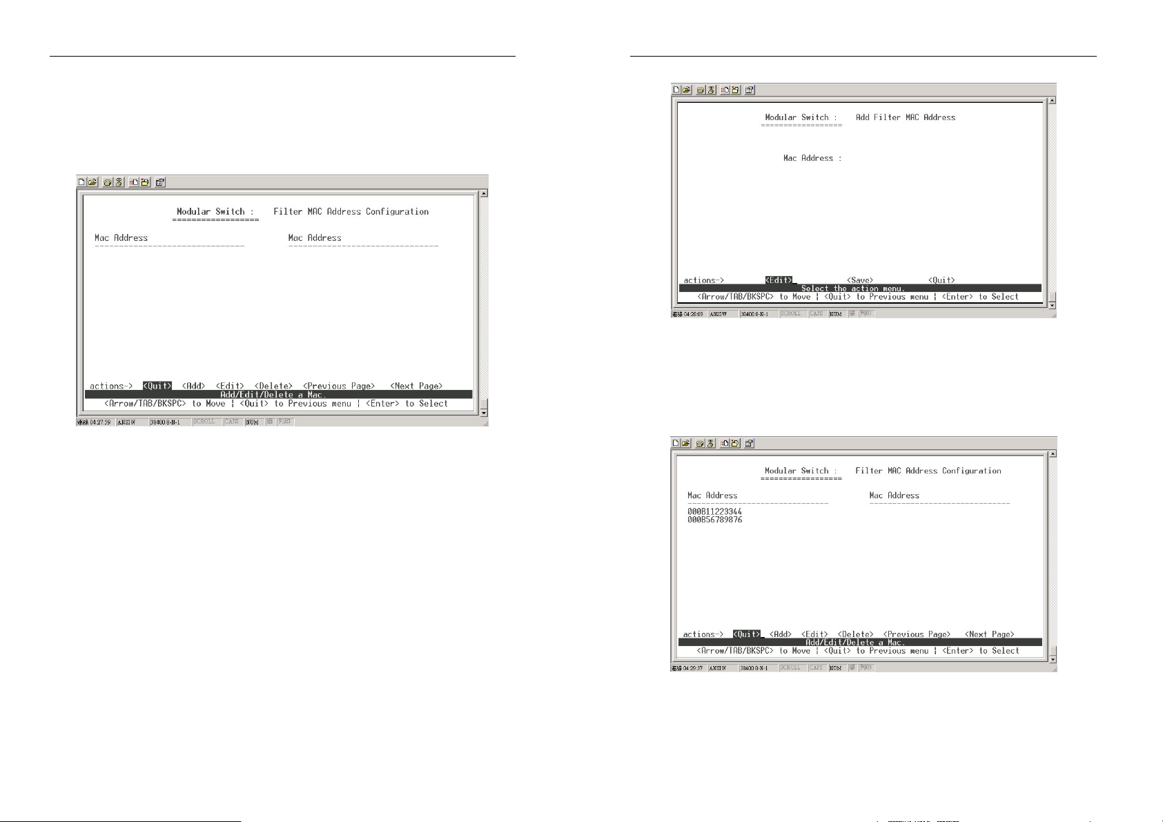
4-2-8-2. Filtering MAC Address
MAC address filtering allows the Switch to drop unwanted traffic. Traffic is
filtered based on the destination addresses. In this page, the user can
add / modify / delete filter MAC address.
Modularized 24+2G Switch
Add filter MAC address
1. Select <Add> and then <Edit> to add a filter MAC address.
2. MAC Address: Type the MAC address to be filtered.
3. Vlan ID: If they are tag-based (802.1Q), VLANs are set up on the
Switch. Type the VID to associate with the MAC address.
4. Press Ctrl+A to go back to the action menu line, and then select
<Save> to save
all configured values.
Edit filter MAC address
1. Press <Edit> key.
2. Choose the MAC address that you want to modify and then press
Enter.
3. Select <Edit> to modify all the items.
4. Press Ctrl+A to go back to the action menu line, and then select
<Save> to save all configured values.
71
72

Modularized 24+2G Switch
Modularized 24+2G Switch
4-3. Protocol Related Configuration
Delete filter MAC address
1. Select
2. Choose the MAC address that you want to delete and then press
Enter.
3. By pressing
<Delete>
<Enter>
to delete a filter MAC address.
once, the deletion will be completed.
4-3-1. Spanning Tree Protocol (STP)
73
74
Modularized 24+2G Switch
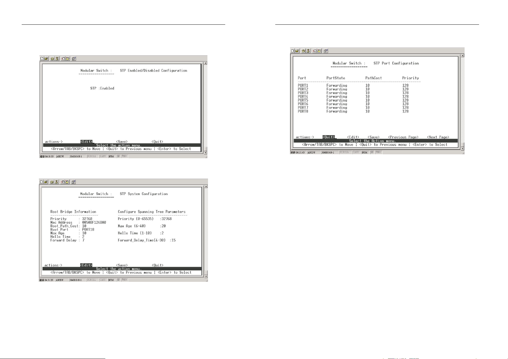
4-3-1-1.STP Enable
Use this page to enable or disable the Spanning Tree function (STP).
Press <Space> key to select enable or disable.
Modularized 24+2G Switch
4-3-1-3. Per Port Configurations
4-3-1-2. System Configuration
1. You can view spanning tree information about the Root Bridge on
the left.
2. On the right, user can set new value for STP parameter.
1. PortState: Display spanning tree status about each port whether it is
forwarding or blocking.
2. Select <Edit>
3. PathCost: Specifies the path cost of the port that the Switch uses to
determine which port are the forwarding ports
4. Priority: This means port priority, you can make it higher or lower or
making it more likely to become the root port
5. Press Ctrl+A go back to the action menu line
6. Select <Save> to save all configured values
7. On the action menu line you can press <Next Page> to configure
port9 ~ port26, press <Previous Page> return to last page.
75
76

Modularized 24+2G Switch
4-3-2. SNMP
Any Network Management running the simple Network Management
Protocol (SNMP) can manage the switch. Use this page to define
management stations as trap managers and to enter SNMP community
strings. User can also define a name, location, and contact person for the
switch.
Modularized 24+2G Switch
1. Press
2. System Name: Type a name to be used for the switch.
3. System Contact: Type the name of contact person or organization.
4. System Location: Type the location of the switch.
5. Press Ctrl+A go back action menu line.
6. Press
4-3-2-2. Community Strings
<Edit>
<Save>
.
to save the configure value.
4-3-2-1. System Options
77
Use this page to Add/ Edit/ Delete SNMP community strings.
1. Community Name: The name of current strings.
2. Write Access: Enable the rights is read only or read-write.
Restricted:
display MIB-object information.
Unrestricted: Read write, enables requests accompanied by this
string to display MIB-object information and to set MIB objects.
Read only, enables requests accompanied by this string to
78
Modularized 24+2G Switch
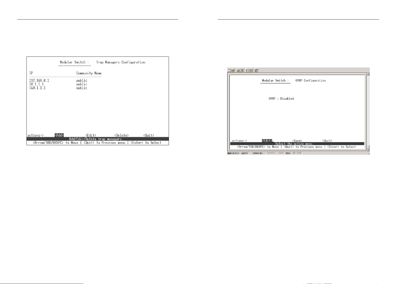
4-3-2-3. Trap Managers
A trap manager is a management station that receives traps, a system
alerts generated by the switch. .If no trap manager is defined, no traps
can be issued. Create a trap manager by entering the IP address of the
station and a community string.
Modularized 24+2G Switch
4-3-3.GVRP
Use this page to enable / disable the GVRP (GARP VLAN Registration
Protocol) support.
1. Select
2. Press Space key to choose Enabled / Disabled.
3. Press Ctrl+A go to the action menu line.
4. Select <Save> to save configured values.
<Edit>
.
79
80

Modularized 24+2G Switch
4-3-4. IGMP
Use this page to enable / disable the IGMP support.
1. Select <Edit>.
2. Press
3. Press Ctrl+A go to the action menu line.
Select <Save> to save configured values.
Space
key to choose Enabled / Disabled.
Modularized 24+2G Switch
4-3-5-1. Working Port Setting
Use this page to set the actual work ports in a trunk group.
1. Select <Edit>.
Group:
2.
Display the trunk group ID.
3. LACP: Display the trunk group’s LACP status.
4. LACP Work Port Num: The maximum number of ports that can be
aggregated at the same time. If it is a LACP static trunking group, the
exceed ports are standby and able to aggregate if work
ports fail. If it
is a local static trunking group, the number must be the same as
group ports.
NOTE: Before setting this page, you have to set the trunk groups on the Trunk
Configurations page first.
4-3-5. LACP
Use this page to configure and view all LACP status.
81
82

Modularized 24+2G Switch
4-3-5-2. State Activity
1. Select <Edit>
2. Press the <Space> key to choose the item.
Active: The port automatically sends LACP protocol packets.
Passive: The port does not automatically send LACP protocol
packets, and responds only if it receives LACP protocol packets from
another device
3. Press
Ctrl+A to
go to the action menu line
4. Select <Save> to save configured values.
If the user set LACP mode in the trunk group, all of the member ports
of this trunk group will be set to and an "Active" status automatically.
Modularized 24+2G Switch
4-3-5-3. LACP Status
When you have set the trunking groups, go to the following page to see
the related Static trunk group information.
<Quit>:
Exit this page and return to previous menu
<Previous Page>: Return to previous page
<Next page>: Go to next page
83
84

Modularized 24+2G Switch
4-3-6. 802.1x Protocol
This page can configure and view all the 802.1x status.
Modularized 24+2G Switch
3. Press Ctrl+A go back action menu line.
4. Select
4-3-6-2. 802.1x System Configuration
<Save>
to save configure value.
4-3-6-1. 802.1x Enable
1.
Select <Edit>.
2. Press Space key to choose Enabled / Disabled.
85
1. Press <Edit>.
2. Radius Server IP Address: the IP address of the authentication
server.
3. Shared Key: A key shared between this switch and authentication
server.
4. NAS, Identifier: A string used to identify this switch.
5. Server Port: The UDP port number used by the authentication server
to authenticate.
6. Accounting Port: The UDP port number used by the authentication
server to retrieve accounting information.
7. Press Ctrl+A go back action menu line.
8. Press <Save> to save configured value.
86
Modularized 24+2G Switch
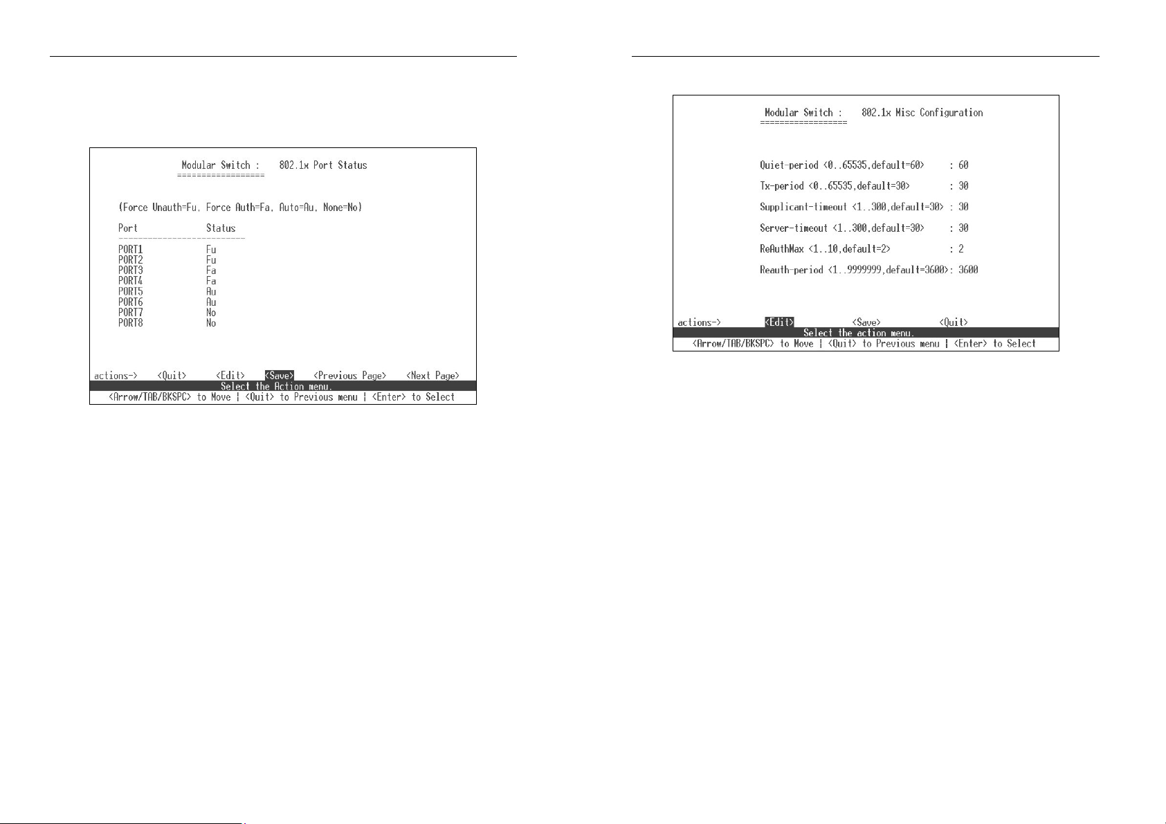
4-3-6-3. 802.1x PerPort Configuration
In this page, set the authorization status to activate 802.1x function by
port setting.
Modularized 24+2G Switch
4-3-6-4. 802.1x Misc Configuration
1. Select <Edit>.
Status:
2.
status.
3. Press Ctrl+A go back action menu line.
4. Select <Save> to save all configure value.
Fu: Force the specific port to be unauthorized.
Fa: Force the specific port to be authorized.
Au: The state of the specific port that was determined by the outcome of
the authentication.
No: The specified port does not support IEEE 802.1x function.
Press
<Space>
key to choose Fu / Fa / Au / No authorization
1. Press <Edit>.
2. Quiet Period: Used to define period of time during which it will not
attempt to acquire a supplicant (Default time is 60 seconds).
3. Tx Period: Used to determine when an EAPOL PDU is to be
transmitted (Default value is 30 seconds).
4. Supplicant Timeout: Used to determine timeout conditions in the
exchange between the supplicant and authentication server (Default
value is 30 seconds).
5. Server Timeout: Used to determine timeout conditions in the exchange
between the authenticator and authentication server (Default value is 30
seconds).
6. ReAuthMax: Used to determine the number of re-authentication
attempts that are permitted before the specific port becomes
unauthorized (Default value is 2 times).
7. Reauth Period: Used to determine a nonzero number of seconds
between periodic re-authentication of the supplications (Default value
is 3600 seconds).
8. Press Ctrl+A go back action menu line.
9. Press <Save> to save configures value.
87
88

4-4. Status and Counters
Modularized 24+2G Switch
Modularized 24+2G Switch
You can press the key of Tab or Backspace to choose item, and press
Enter key to select item.
4-4-1. Port Status
This page displays the status of each port.
Link Status:
InRate: Displays the input rate control (100K/unit) setting value.
OutRate: Displays the output rate control (100K/unit) setting value.
Enabled:
Auto: Displays the port NWay link mode: Auto, NWay_Force,
Spd/Dpx:
FlowCtrl: In auto / NWay force mode, the display for the flow
Displays whether the port is linked or not linked.
Displays whether the port is enabled or disable.
Depending on the user’s setting a “Yes“ or “No” status
will be displayed respectively. If the port is not linked its
status be treated as “No”.
Force.
Displays the port speed and duplex.
control status is enable or disable after auto-negotiation.
In force mode, the display for flow control status is enable
or disable depending on the user’s setting.
89
<Quit>: Exit the port status page, and return to the previous menu.
<Previous Page>: Display previous page.
<Next page>: Display next page.
4-4-2. Port Counters
The following information provides a view of the current status of the unit.
<Quit>:
<Reset All>: Set all counts to 0.
<Previous Page>: Display previous page.
<Next page>:
Exit the port status page and return to previous menu.
Display next page.
90

Modularized 24+2G Switch
Modularized 24+2G Switch
4-4-3. System Information
MAC Address: Media Access Control - The unique hardware
address assigned by manufacturer.
Firmware Version: Display the Switch’s firmware version.
4-4-4. Network Information
Display network devices
91
92

Modularized 24+2G Switch
Modularized 24+2G Switch
4-5. Reboot Switch
4-5-1. Default
Reset Switch to default configurations.
Press “Y”, the Switch will load default setting. After load of default settings
is completed, the Switch will reboot automatically.
4-5-2. Restart
Reboots the Switch with software reset.
4-6. TFTP Update Firmware
Use this page to update firmware or restore EEPROM value or upload
current EEPROM value.
4-6-1. TFTP Update Firmware
Use this page to update firmware via TFTP
1. Start the TFTP server, and copy firmware update version image file to
TFTP server.
2. Select <Edit> on this page.
3. TFTP Server: Type the IP of TFTP server.
Remote File Name:
4.
5. Press Ctrl+A to go to the action line.
6. Select <Save>, the Switch will start to download the image file.
7. When the update is successful, the image file will be downloaded.
8. Restart the Switch to launch the version of firmware.
Type the image file name.
93
94

Modularized 24+2G Switch
4-6-2. Restore Configure File
Use this page to restore EEPROM value from a saved image file in a
TFTP server.
1. Start the TFTP server.
2. Select <Edit> on this page.
3. TFTP Server: Type the IP of TFTP server.
4. Remote File Name: Type the image file name.
5. Press
6. Select <Save>. The Switch will start to download the image file.
8. When the restore function is successful, the image is downloaded.
9. Restart the Switch to resume normal operations.
Ctrl+A
to go to the action line.
Modularized 24+2G Switch
4-6-3. Backup Configure File
Use this page to save the current EEPROM value to image file. Then
when necessary, go to the update configure page to retrieve the
EEPROM value.
1. Start the TFTP server.
2. Select
3. TFTP Server: Type the IP of TFTP server.
4. Remote File Name: Type the image file name.
5. Press Ctrl+A to go to the action line.
6. Select <Save>. The Switch will start to save the image file.
6. When backup function successfully, the image file is saved to the
designated TFTP server.
7. Follow the instructions given in the Restore Configure File page to
restore lost settings
<Edit>
on this page.
95
96

Modularized 24+2G Switch
Modularized 24+2G Switch
5.
Menu Driven
Interface via
Telnet
This section provides some basic instructions to using Menu Driven
Interface to configure the Switch. Follow the instructions below:
1. Open a Command Prompt window and type
telnet xxx.xxx.xxx.xxx where xxx represents the IP address.
As an example, we’ll continue to use the IP address configured
in part A of this manual: 192.168.0.197
2. Then “Press <ENTER> key to start”
Login
6.
Troubleshooting
The network administrator can observe and monitor most areas of the
Switch status using the LED indicators on the front panel to quickly identify
problems. This section contains a few of the more common problems that
may arise and possible solutions.
Symptom: Power indicator does not light up after power on.
Cause:
Solution: Verify if the power outlet is functioning normally by plugging in
Symptom: Link indicator does not light up after making a connection.
Cause: Network cable or fiber switch port is defective.
Solution: Ensure that the attached device and switch are powered on.
Symptom: Unit powers off during operation after a period of time.
Cause: Loose power connections, power surges/loss or inadequate
Solution: Ensure that all power connections are secure and that the unit
Defective power outlet, power cord or internal power supply.
another properly operating device. Connect the power cord to
another device to test. If these two tests fail to resolve the
problem, replace the power supply unit.
Verify that the fiber cable has been properly connected to both
devices. Review that the cabling distance does not exceed
specified limits. Inspect cable for defects and replace if
necessary.
ventilation.
fans have proper ventilation. If unable to correct the problem by
above measures, it may be necessary to replace internal
power supply unit.
3. The default Login name is “admin” with no preset password.
The system provides a menu-driven user interfaces via console or
telnet. After you log into the system, you will see a window similar
to that as the console interface like in the section 1. To use the
management facilities of the switch via telnet, please see section
four.
97
98

Modularized 24+2G Switch
Modularized 24+2G Switch
LAN Switch
Appendix A
Application Examples
Building to Building (Small Campus)
In the figure below, the Switch is functioning as a backbone for a small
campus network configuration. It is providing a max. of 200 Mbps full
duplex link to a remote stack of 10/100 switches.
BUILDING C
BUILDING B
BUILDING A
Enterprise Server Aggregation
In the figure below, the Switch is functioning as a server aggregation for an
enterprise or LAN configuration. It is providing a 200 Mbps full duplex link
to a workgroups of 10/100 switches located on separate floors within a
single building.
FLOOR 10
GROUND
FLOOR
FLOOR 5
In the figure below, the Switch is functioning as a high-speed bridge
between segments creating increased capacity for each user (node) on
the local area network. It is providing a 200 Mbps full duplex link to a
variety of Ethernet / Fast Ethernet network devices within a LAN.
UP TO 24 NETWORK NODES CONNECTED
-10/100Mbps over copper segments
-100Mbps over fiber segments
99
100

Modularized 24+2G Switch
Appendix B
802.1Q Tag-VLAN Application Example
An IEEE 802.1Q VLAN is a group of ports that can be located anywhere in the
network, but communicate as though they belong to the same physical segment.
VLANs help to simplify network management by allowing you to move devices
to a new VLAN without having to change any physical connections. VLANs can
be easily organized to reflect departmental groups (such as Marketing or R&D),
usage groups (such as e-mail), or multicast groups (used for multimedia
applications such as videoconferencing).
VLANs provide greater network efficiency by reducing broadcast traffic, and
allow you to make network changes without having to update IP addresses or IP
subnets. VLANs inherently provide a high level of network security since traffic
must pass through a configured Layer 3 link to reach a different VLAN. Figure 1
demonstrate a VLAN example with 2 switches and 4 VLAN groups. Below are
details and configuration steps .
Internet
v102
IP: 137.92.254.11
SW2
IP: 137.92.254.10
v176
2 16 20 22 2418141210864
1 15 19 21 231713119753
PC 201 PC 205PC 203PC 202
v176
SW1
1 15 19 21 231713119753
2 16 20 22 2418141210864
PC 101 PC 103PC 102 PC 104
v102
v2
PC 204
Figure 1. 802.1Q Tag-VLAN example
25 26
untag-frame
v2
tag frame
vid 254, 176, 102, 2
25 26
tag frame
vid 254, 176, 102, 2
Port 25, 26 are members of
VLAN v254, v176, v102 and v2
tag frame
vid 254, 176, 102, 2
Port 25, 26 are members of
VLAN v254, v176, v102 and v2
v254
v176
v102
v2
Router
VLAN define
VIDName
254
176
102
2
Color
Modularized 24+2G Switch
Netwrok topology
In Fig 1, we will have a fibre (1000SX) carrying tagged VLANs with trivial
VIDs (254,176,102,2) only. This will be connected to the uplink port (26) on a
switch SW1. The internal management interface of this SW1 will have an IP
address on VLAN VID 254 (e.g. 137.92.254.10). A 1000SX port (25) on this
SW1 will then be connected to the uplink port (26) on SW2 and it will carry
tagged packets VIDS (254.176.102.2). Again the management port of the SW2
will be on VLANs VID 254 (e.g. 137.92.254.11). We will have a few ports on
the 550+ to egress untagged packets on VLANs 254.76.102.2. And we can
telnet/SNMP the management interfaces of both the SW1 and the SW2. That a
laptop on either VLANs 254.176.102.3 can see the rest of the network(s).
Internet
v102
v176
SW2
IP: 137.92.254.11
untag-frame
IP: 137.92.254.10
untag-frame
v176
2 16 20 22 2418141210864
1 15 19 21 231713119753
IP: 137.92.254.x /24
PC 201
SW1
PC 101
untag-frame
1 15 19 21 231713119753
2 16 20 22 2418141210864
untag-frame
IP: 137.92.254.x /24
v102
v2
Figure 2. Communications between PC101 & PC201 with tagged-VLAN.
v2
tag-frame
25 26
VLAN v254, v176, v102 and v2
25 26
tag-frame
Port 25, 26 are members of
Port 25, 26 are members of
VLAN v254, v176, v102 and v2
v254
v176
v102
v2
Router
VLAN define
VIDName
254
176
102
2
Color
101
102

Modularized 24+2G Switch
Switch Configuration
SW1 Configuration Steps – using menu-driven
Step 1. Configure PVID
[Switch Static Configuration] B [VLAN Configuration]
B [VLAN Configure]
Select VLAN mode (802.1Q)
PVID cofiguration : please refer to “PVID Configuration Table”
PVID Configuration Table
PVID
176 1~6
102 7~10
2 13~18
254 25, 26
1 (default) 11,12,19~24
Step 2 . Create VLAN Group : v176, 102, v2, v254
[Switch Static Configuration] B [VLAN Configuration]
B [Create a VLAN Group
]
Port #
Modularized 24+2G Switch
VLAN configuration: please refer to “VLAN Configuration Table”
VLAN Configuration Table
VLAN Config. Port Member (port #)
Name VID untagged tagged no
Default 1 11, 12, 21~24 25, 26 else
v176 176 1~6 25, 26 else
v102 102 5~10 25, 26 else
v2 2 13~18 25, 26 else
v254 254
Step 3. Edit “Default” VLANs
²
25, 26 else
103
104

Modularized 24+2G Switch
[Switch Static Configuration] B [VLAN Configuration]
B [Edit/Delete a VLAN Group]
VLAN configuration: please refer to “VLAN Configuration Table” above.
SW2 Configuration Steps – using menu-driven
Step 1. Configure PVID
Modularized 24+2G Switch
Select VLAN mode (802.1Q)
PVID configuration
: please refer to “PVID Configuration Table”
PVID Configuration Table
PVID
176 1~8
102 9~14
2 15~20
254 25, 26
1 (default) 21~24
Step 2 . Create VLAN Group : v176, 102, v2, v254
[Switch Static Configuration] B [VLAN Configuration]
B
[Create a VLAN Group]
VLAN configuration: please refer to “VLAN Configuration Table”
VLAN Configuration Table
VLAN Config. Port Member (port #)
Name VID untagged tagged no
Default 1 21~24 25, 26 else
v176 176 1~8 25, 26 else
v102 102 5~14 25, 26 else
v2 2 13~20 25, 26 else
v254 254
²
Port #
25, 26 else
[Switch Static Configuration] B [VLAN Configuration]
B [VLAN Configure]
105
106

Step 3. Edit “Default” vlan
Modularized 24+2G Switch
Modularized 24+2G Switch
Connecting
VLAN Groups
The switch supports communication within a common VLAN. However, if you
have devices in separate VLANs that need to communicate, and it is not
practical to include these devices in a common VLAN, then the VLANs can be
connected via the Layer 3 routing provided by another Layer 3 switch. In Fig 3,
we use the router with two network interfaces (192.168.0.1 /24, 192.168.1.1 /24)
to provide the Layer 3 routing.
v176
SW1
IP: 192.168.0.100
Internet
Router
tag-fram
1 15 19 21 231713119753
2 16 20 22 2418141210864
tag-fram
v102
v2
25 26
tag-fram
tag-fram
Port 25, 26 are members of
VLAN v254, v176, v102 and v2
192.168.0.1 /24
192.168.1.1 /24
[Switch Static Configuration] B [VLAN Configuration]
B[Edit/Delete a VLAN Group]
VLAN configuration: please refer to “VLAN Configuration Table” above.
107
SW2
IP: 192.168.0.200
2 16 20 22 2418141210864
1 15 19 21 231713119753
untag-frame
PC 201 PC 205
192.168.0.0.x /24
untag-frame
192.168.0.1.x /24
25 26
Port 25, 26 are members of
VLAN v254, v176, v102 and v2
v254
v176
v102
v2
VLAN define
VIDName
254
176
102
2
Color
Fig 3. VLAN groups communication.
108
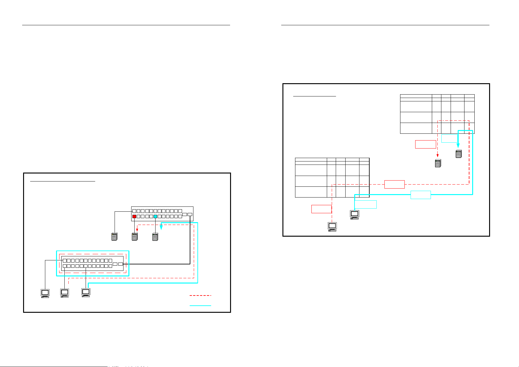
Modularized 24+2G Switch
Modularized 24+2G Switch
Appendix C
Protocol VLAN Application Example
In order for an end station to send packets to different VLANs, itself has to be
either capable of tagging packets it sends with VLAN tags or attached to a
VLAN-aware bridge that is capable of classifying and tagging the packet with
different VLAN ID based on not only default PVID but also other information
about the packet, such as the protocol. The Protocol-based VLAN feature of the
switch can be applied for accommodating devices that you want to participate in
the VLAN by means of built-in knowledge of layer 2 packet formats used by
selected popular protocols, such as IP and Novell IPX. The following example
will demonstrate you how to configure the switch for protocol—based VLAN
application.
Figure 1 shows you two switches with workstations and servers which are going
to work by using protocol VLAN.
Protocol VLAN Example-Construction
Switch-2
<PVID> Port Pvid
1 10
2 10
11 10
26 10
<VID> VLAN-Name Vid Protocol Member
V-10 10 none 1~25(untag),26 (tag)
V-IP-20 20 IP 1~25(untag),26 (tag)
V-IPX-30 30 IPX 1~25(untag),26(tag)
Other-Protocol-Server
IP-Server
Switch-1
<PVID> Port Pvid
1 10
2 10
11 10
26 10
<VID> VLAN-Name Vid Protocol Member
V-10 10 none 1~25(untag),26(tag)
V-IP-20 20 IP 1 (untag) , 26(tag)
V-IPX-30 30 IPX 11(untag) , 26(tag)
2 16 20 22 2418141210864
1 15 19 21 231713119753
IPX-Server
25
26
Figure 2 shows you the internal settings and data flows in the switches. In this
application, the IP frames from workstations will go to the IP server only and the
IPX frames will go to the IPX server only.
<tag frame >
vid:20
Switch-1
Port 1 2 11 26
Pvid 10 10 10 10
Protocol : none
Protocol : IP
Protocol :IPX
VLAN-10
Vid:10
VLAN-20
Vid:20
VLAN-30
Vid:30
<tag frame >
untag untag untag tag
untag
NO
<untag frame >
IP-Server
vid:30
NO NO
NO untag tag
<untag frame >
IPX-Server
tag
Protocol VLAN Example
Switch-2
port 1 2 11 26
pvid 10 10 10 10
Protocol : none
Protocol : IP
Protocol :IPX
VLAN-10
Vid:10
VLAN-20
Vid:20
VLAN-30
Vid:30
IP protocol packets
untag untag untag tag
untag untag untag tag
untag untag untag tag
<untag frame >
IP-Workstation
IPX protocol packet s
IPX-Workstation
<untag frame >
Figure 2 .
Other-Protocol-Workstation
2 16 20 22 2418141210864
1 15 19 21 231713119753
IP-Workstation
25
26
IPX-Workstation
Figure 1. Protocol VLAN Example
109
IP-path
IPX-path
110
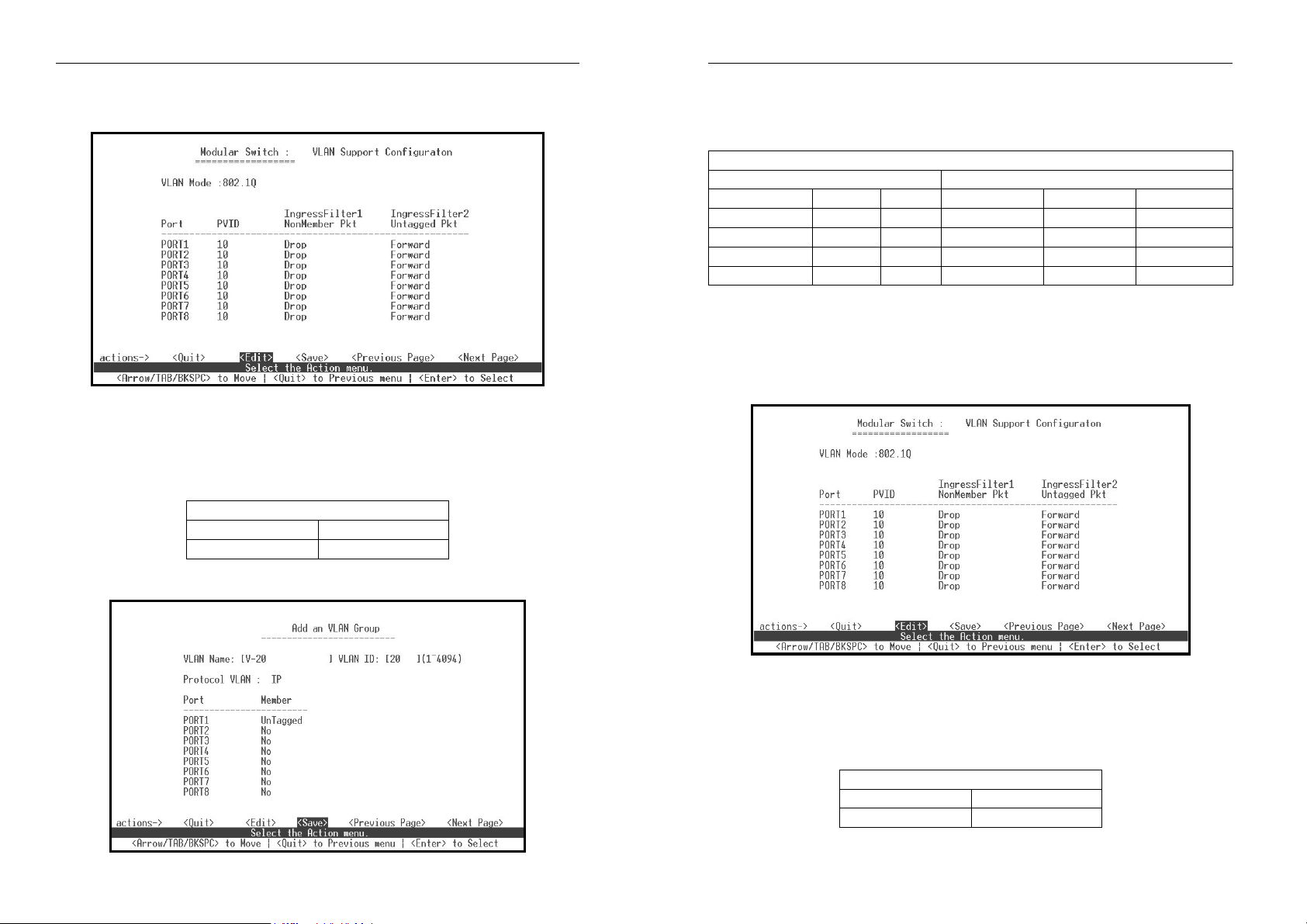
Modularized 24+2G Switch
SW1. Configuration Steps – using menu-driven
Step 1. Configure PVID
[Switch Static Configuration] B [VLAN Configuration]
B [VLAN Configure]
Select VLAN mode (802.1Q)
PVID configuration
: please refer to “PVID Configuration Table”
PVID Configuration Table
PVID
10 1~26
Port #
Step 2 . Create VLAN Group : V-10, V-IP-20, V-IPX-30
Modularized 24+2G Switch
[Switch Static Configuration] B [VLAN Configuration]
B
[Create a VLAN Group
VLAN configuration: please refer to “VLAN Configuration Table”
]
VLAN Configuration Table
VLAN Config. Port Member (port #)
Name VID Protocol untagged tagged no
Default 1 None X X 1~26
V-10 10 None 1~25 26 X
V-IP-20 20 Ip 1 26 else
V-IPX-30 30 Ipx 11 26 else
SW2. Configuration Steps – using menu-driven
Step 1. Configure PVID
111
[Switch Static Configuration] B [VLAN Configuration]
B [VLAN Configure]
Select VLAN mode (802.1Q)
PVID configuration: please refer to “PVID Configuration Table”
PVID Configuration Table
PVID
10 1~26
112
Port #

Modularized 24+2G Switch
Step 2 . Create VLAN Group: V-10, V-IP-20, V-IPX-30
[Switch Static Configuration] B [VLAN Configuration]
B [Create a VLAN Group
VLAN configuration: please refer to “VLAN Configuration Table”
]
VLAN Configuration Table
VLAN Config. Port Member (port #)
Name VID Protocol untagged tagged no
Default 1 None X X 1~26
V-10 10 None 1~25 26 X
V-IP-20 20 Ip 1~25 26 X
V-IPX-30 30 Ipx 1~25 26 X
113
 Loading...