

Page 1
µMIDI Manual
µMIDI Manual
USB/DIN MIDI Voice and Clock Interface
Manual Revision: 1.0
Page 2

µMIDI Manual
Table of Contents
Table of Contents
Overview
Features
Installation
Before Your Start
Installing Your Module
Front Panel
Controls
Outputs
Connection
DIN MIDI Devices
Computer
iPhone or iPad
Operation
Portamento (Glide)
Customization
Firmware Updates
Technical Specifications
MIDI Implementation Chart
Page 1
Page 3

µMIDI Manual
Overview
The µMIDI provides all the essentials to control and sync your Eurorack modular from your
computer, iPhone/iPad, or hardware MIDI device with a minimum of fuss. No menu diving or
configuration scripts, just two buttons. The connectivity, feature set, and compact size make the
µMIDI ideal for integrating your modular with the rest of your rig while not taking up too much
space in your case.
The upper clock section features a dedicated 16th note clock output ideal for synchronizing a
Eurorack sequencer like the Metropolis. A second clock output with selectable divisions can be
used when difference sync events are needed. The run and reset outputs can be used to reset
your Eurorack sequencers in tandem with any external sequencer or DAW.
The lower half of the µMIDI gives you everything you need to control a single voice synth via
MIDI. Just connect either a USB or DIN MIDI cable to the module, LEARN a channel, and start
playing.
Future firmware updates over USB are made easy with the Firmware Updater software.
Features
● High speed ARM processor for low latency & jitter.
● DIN or USB MIDI input.
● Two clock outputs, one with selectable divisions.
● Sequencer sync via run and reset outputs.
● Precision 0 – 10 V note pitch output with pitch bend & portamento CC support.
● Gate and trigger outputs for envelope triggering.
● Mod wheel and continuous controller outputs for additional modulation.
● Firmware updates over USB.
Page 2
Page 4

µMIDI Manual
Installation
Intellijel Eurorack modules are designed to be used with a Eurorack-compatible case and power
supply.
Before Your Start
Before installing a new module in your case you must ensure your case’s power supply has
sufficient available capacity to power the module:
● Sum up the specified +12V current draw for all modules, including the new one. Do the
same for the -12 V and +5V current draw. The current draw will be specified in the
manufacturer's technical specifications for each module.
● Compare each of the sums to specifications for your case’s power supply.
● Only proceed with installation if none of the values exceeds the power supply’s
specifications. Otherwise you must remove modules to free up capacity or upgrade your
power supply.
You will also need to ensure you have enough free space (hp) as well as free power headers in
your case to fit the new module.
You can use a tool like ModularGrid to assist in your planning. Failure to adequately power your
modules may result in damage to your modules or power supply. If you are unsure, please
contact us before proceeding.
Installing Your Module
When installing or removing a module from your case always turn off the power to the case and
disconnect the power cable. Failure to do so may result in serious injury or equipment damage.
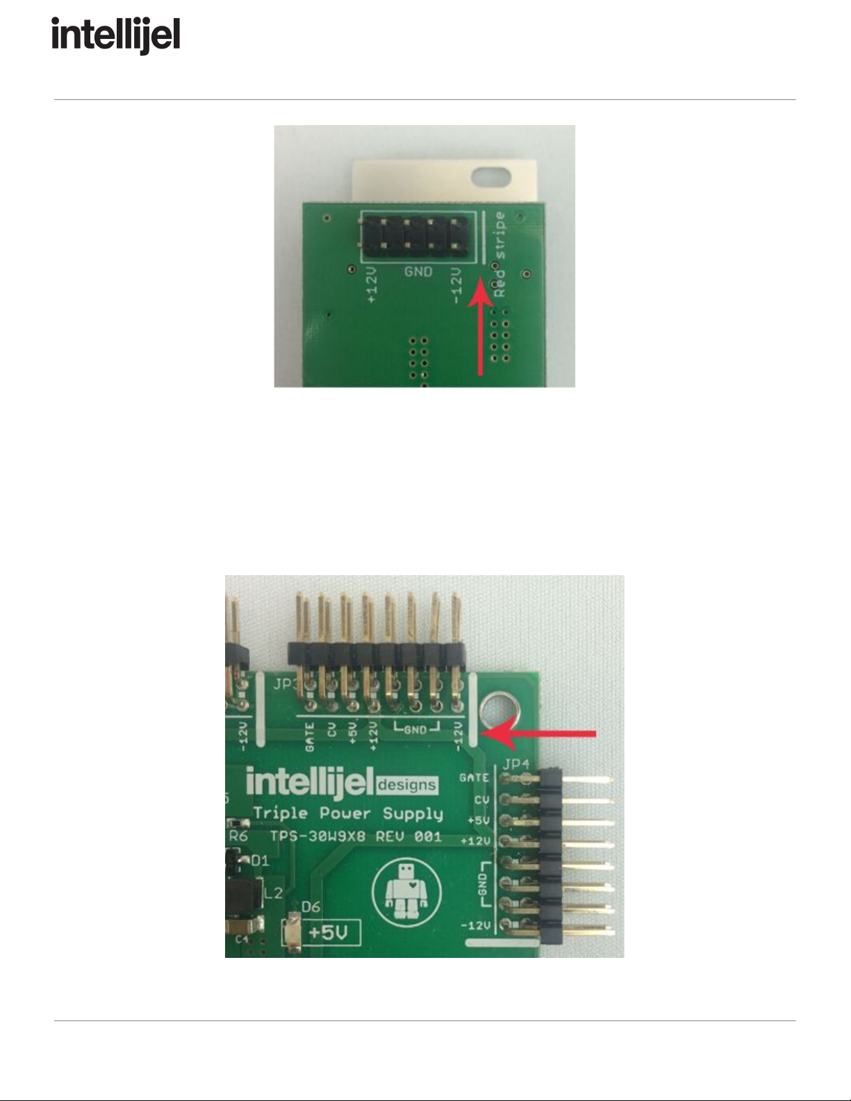
Ensure the 10-pin connector on the power cable is connected correctly to the module before
proceeding. The red stripe on the cable must line up with the -12V pins on the module’s power
connector. The pins are indicated with the label -12V, a white stripe next to the connector, the
words “red stripe”, or some combination of those indicators.
Page 3
Page 5
µMIDI Manual
Most modules will come with the cable already connected but it is good to double check the
orientation. Be aware that some modules may have headers that serve other purposes so
ensure the cable is connected to the right one.
The other end of the cable, with a 16-pin connector, connects to the power bus board of your
Eurorack case. Ensure the red stripe on the cable lines up with the -12V pins on the bus board.
On Intellijel power supplies the pins are labelled with the label “-12V” and a thick white stripe:
Page 4
Page 6

µMIDI Manual
If you are using another manufacturer’s power supply, check their documentation for
instructions.
Once connected, the cabling between a module and power supply should resemble the picture
below:
Before reconnecting power and turning on your modular system, double check that the ribbon
cable is fully seated on both ends and that all the pins are correctly aligned. If the pins are
misaligned in any direction or the ribbon is backwards you can cause damage to your module,
power supply, or other modules.
After you have confirmed all the connections, you can reconnect the power cable and turn on
your modular system. You should immediately check that all your modules have powered on
and are functioning correctly. If you notice any anomalies, turn your system off right away and
check your cabling again for mistakes.
Page 5
Page 7

µMIDI Manual
Front Panel
Controls
1. DIN MIDI Input - For connecting to 5-pin DIN MIDI outputs of controllers, synths, drum
machines etc.
2. USB Connector - For connecting to computers, iPhones, iPads, other USB MIDI hosts.
3. LEARN - This button can be used to learn the MIDI channel on which the µMIDI will
accept notes and controller values. Pressing the button once will cause the lights on the
module to blink in a cycle until the first note message is received. The listening channel
Page 6
Page 8

µMIDI Manual
will then be set to the channel of the note, and messages on other channels will be
ignored.Another function of the button is to save settings. Press and hold the button for
one second or longer to save the current clock division and learned channel to memory.
The settings will be recalled the next time your system is powered on.
4. + - The division button sets the clock division of the MIDI clock that is sent from the CLK
output. The default setting is 6, the same as the 1/16th output. Pressing the button
repeatedly cycles through the different divisions: 6 (1/16 notes), 12 (1/8 notes), 24 (1/4
notes), 48 (1/2 notes), 96 (whole notes, eg: every measure), 1 (24 ppq), 3 (1/32 notes).
Outputs
A. 1/16th - Trigger output which outputs a divided MIDI clock with a fixed division of 6,
equivalent to 1/16th notes. Suitable for connecting to sequencer clock inputs such as the
Metropolis.
B. CLK - Trigger output which outputs a divided MIDI clock with a division set by the ÷
button.
C. RUN - Gate output which goes high when a MIDI start or continue message is received
and low when a stop message is received.
D. RESET - Trigger output which sends a trigger when a MIDI reset message is received.
E. PITCH - 1 V/octave CV output with a range of 0 – 10 V. The voltage output is
determined by the pitch of the last played note and the pitch bend control. MIDI
note 0 (C-2) maps to 0 V and note 120 (C8) maps to 10 V.
F. MOD - CV output with a range of 0 – 5 V. The voltage is proportional to the position of
the mod wheel control. Suitable for connecting to the CV input of a VCA controlling
modulation depth.
G. VEL - CV output with a range of 0 – 5 V. The voltage is proportional to the velocity of the
last played MIDI note. Suitable for connecting to the LEVEL input of an envelope
generator such as the Atlantis envelope section or Dual ADSR.
H. CC - CV output with a range of 0 – 5 V. The voltage is proportional to the value sent by
MIDI CC #2.
I. GATE - Gate output which is high when a note is being played. Suitable for connecting
to the GATE input of an envelope such as the Atlantis envelope section or Dual ADSR.
J. TRIG - Trigger output which sends a trigger when a MIDI note on message is received.
Suitable for connecting to the TRIG input of an envelope generator such as the Atlantis
envelope section or Dual ADSR.
Page 7
Page 9

µMIDI Manual
Connection
DIN MIDI Devices
Connect a 5-pin MIDI DIN cable from the MIDI Out or MIDI Thru port of another MIDI device
such as a controller, drum machine, or synthesizer, to the MIDI DIN port at the top of the µMIDI.
Computer
The µMIDI can be connected to a Mac or PC using a USB A to B cable. As it is a USB MIDI
class-compliant device, no drivers are required.
iPhone or iPad
The µMIDI can be connected to an iPhone or iPad using the Apple Lightning to USB Camera
Adaptor . Connect a USB A to B cable between the adaptor and the module’s USB port then
connect the adaptor to your iDevice.
Operation
If you are only using MIDI clock then no further action is required. Upon receiving any MIDI
clock or transport messages the clock trigger outputs of the µMIDI will function as described in
the Front Panel section above.
If you are controlling a voice with MIDI messages you need to ensure the µMIDI is set to the
channel on which the messages are being sent. The default channel is 1 but can be changed by
pushing the LEARN button to put the module in to learn mode. When in learn mode the next
received note message will be used to set the listening channel. If you wish to save the learned
channel simply press and hold the button until the lights on the module all blink. The next time
the module powers on it will default to the newly saved channel.
Entering learn mode also resets the voice outputs in the event you get stuck notes or wish to
reset the outputs for some other reason. You can push the LEARN button again to exit learn
mode if you don’t need to change MIDI channels.
Portamento (Glide)
The µMIDI is capable of slewing the pitch output to achieve portamento effects. Portamento is
enabled by using the standard MIDI portamento controls:
Page 8
Page 10

µMIDI Manual
● Send CC 65 (Portamento Control) with a value of 127 to enable portamento
● Use CC 5 (Portamento Time MSB) for coarse control of the portamento time, or CC 37
(Portamento Time LSB) for fine control.
● You can disable portamento by sending CC 65 (Portamento Control) with a value of 0.
Customization
The operation of the µMIDI can be customized by visiting the µMIDI Configuration Utility web
page. You must use a recent version of Google Chrome and connect the µMIDI module to your
computer via the USB cable.
Firmware Updates
Firmware for the µMIDI can be updated using the Intellijel Firmware Updater. With your modular
system powered off, connect a USB cable between the module and your PC or Mac. Power on
your modular while holding down the LEARN button. Then follow the instructions on the
firmware updater page.
Technical Specifications
Width
6 hp
Maximum Depth
40 mm
Current Draw
47 mA @ +12V
3 mA @ -12V
Page 9
Page 11

µMIDI Manual
MIDI Implementation Chart
Page 10
Page 12

µMIDI Manual
Page 11
Page 13

µMIDI Manual
Page 12
Page 14

µMIDI Manual
Page 13
Page 15

µMIDI Manual
Page 14
Page 16

µMIDI Manual
Page 15
 Loading...