

Page 1
Triatt Manual
Overview
The Triatt is a 3-channel attenuverter and summing mixer.
Installation
See the Module Installation Guide for instructions on installing the module in your Eurorack modular
system.
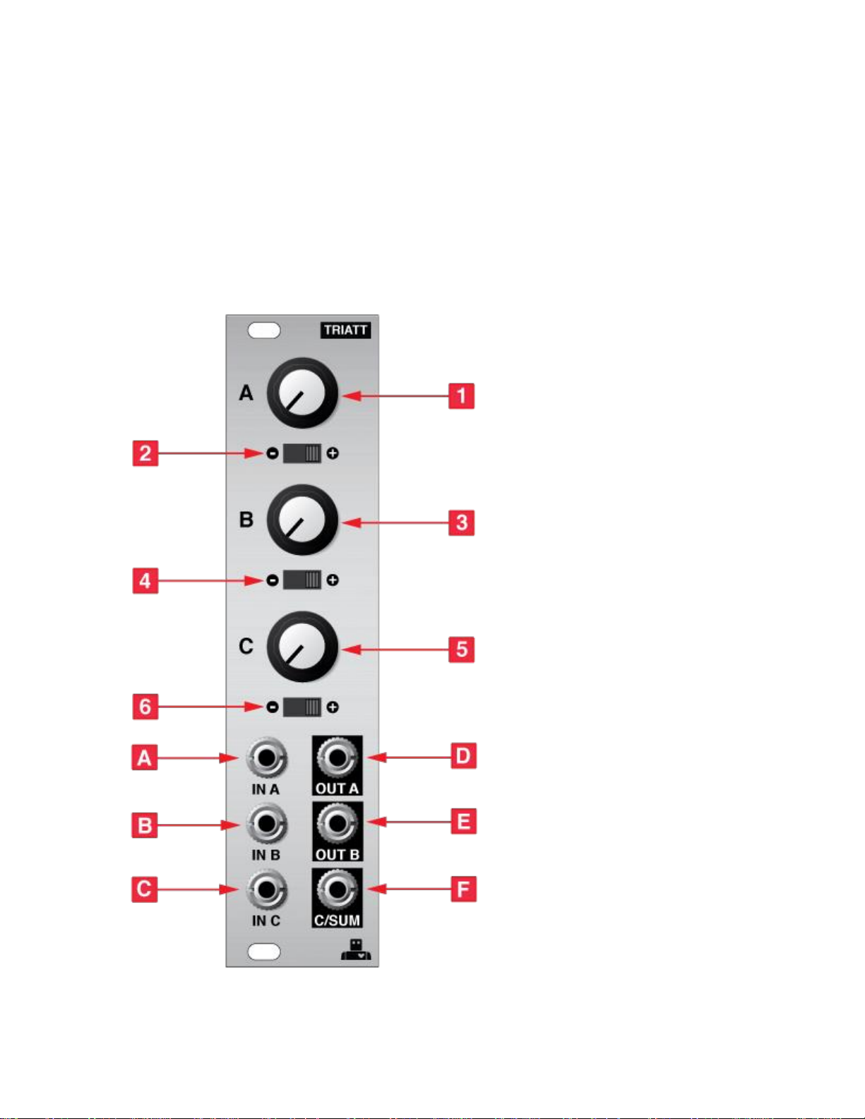
Front Panel
Page 2

Controls
1. Channel A attenuator
Sets the amount of attenuation for the IN A input. The behaviour of the knob depends on the position
of the polarity switch [2]. The attenuation amount is linear.
2. Channel A polarity switch
This is a 3-position switch that sets the polarity of the of the OUT A signal. With the switch in the right
position the channel functions as a standard attenuator. OUT A outputs the unmodified signal from IN
A when the attenuator knob is fully clockwise and no signal (0 V) when the knob is fully
counterclockwise.With the switch in the left position the channel functions as an inverting
attenuator. OUT A outputs the inverse of the signal at IN A when the knob is fully clockwise and no
signal when it is fully counterclockwise. For example, if the input is 5 V the output will be -5 V with the
knob fully clockwise.
With the switch in the middle position the channel acts a bipolar attenuverter. The output is the
unmodified input with the knob fully clockwise, the inverse of the input with the knob fully
counterclockwise, and 0 V when the knob is at the 12 o’clock position.
3. Channel B attenuator
Behaves the same as the Channel A attenuator but for channel B.
4. Channel B polarity switch
Behaves the same as the Channel A polarity switch but for channel B.
5. Channel C attenuator
Behaves the same as the Channel A attenuator but for channel C.
6. Channel C polarity switch
Behaves the same as the Channel A polarity switch but for channel C.
Inputs & Outputs
A. IN A
Input for channel A. When no cable is plugged in to the input is either 5 V or 10 V depending on the
position of the corresponding jumper on the rear of the module.
B. IN B
Input for channel B. When no cable is plugged in to the input is either 5 V or 10 V depending on the
position of the corresponding jumper on the rear of the module.
C. IN C
Input for channel C. When no cable is plugged in to the input is either 5 V or 10 V depending on the
position of the corresponding jumper on the rear of the module.
D. OUT A
Output for channel A. Plugging a cable into this jack removes the output from the SUM mix.
E. OUT B
Output for channel B. Plugging a cable into this jack removes the output from the SUM mix.
F. C/SUM
With no cables connected to OUT A or OUT B this output is a sum of the outputs of channels A, B,
and C. Connecting a cable to OUT A or OUT Bremoves their output from this sum. To get the output
of only the C channel, both A and B should be output separately.
Page 3

Rear Jumpers
The rear panel of the module features three jumpers that can be used to set the voltage that’s passed to
the input of each channel when no cable is connected. This feature allows the module to be used as a
manually variable voltage without needing to apply any input signal. When the jumper is between the top
and middle pin the voltage at the input is 5 V, and when it is between the bottom and middle pin the
voltage is 10 V.
Ensure the modular system is powered off before changing the jumper setting.
 Loading...