

Page 1

Audio Interface II Manual
Audio Interface II
Eurorack <-> Line Level Audio Interface
Manual Revision: 1.0
Page 2

Audio Interface II Manual
Overview
The Audio Interface II allows you to interface your Eurorack modular system to the pro balanced
line level world (+4 dBu). You can send and return to rack mount/desktop fx units, patch to
external line level instruments like synths and drum machines, interface to a DAW and much
more.
Features
● 2 x Balanced TRS 1/4″ to Eurorack modular level input paths
● 2 x Eurorack modular level signals to Balanced TRS 1/4″ output paths
● 4 x six stage led VU meter to monitor all inputs and outputs simultaneously
● Uses high quality THAT Corp balanced line drivers and receiver ICs
● Input path has up to 20 dB of gain which allows you to patch in low level consumer level
signals and boost them. 0 dB = 10 Vpp (nominal Eurorack level)
● Output path steps a nominal Eurorack level (10 Vpp) down to +4 dBu with up to +6 dB
gain
● Skiff friendly
Page 1
Page 3

Audio Interface II Manual
Table of Contents
Overview
Features
Table of Contents
Installation
Before Your Start
Installing Your Module
Front Panel
Controls
Inputs & Outputs
Instruction
Input From an External Source
Technical Specifications
Page 2
Page 4

Audio Interface II Manual
Installation
Intellijel Eurorack modules are designed to be used with a Eurorack-compatible case and power
supply.
Before Your Start
Before installing a new module in your case you must ensure your case’s power supply has
sufficient available capacity to power the module:
● Sum up the specified +12V current draw for all modules, including the new one. Do the
same for the -12 V and +5V current draw. The current draw will be specified in the
manufacturer's technical specifications for each module.
● Compare each of the sums to specifications for your case’s power supply.
● Only proceed with installation if none of the values exceeds the power supply’s
specifications. Otherwise you must remove modules to free up capacity or upgrade your
power supply.
You will also need to ensure you have enough free space (hp) as well as free power headers in
your case to fit the new module.
You can use a tool like ModularGrid to assist in your planning. Failure to adequately power your
modules may result in damage to your modules or power supply. If you are unsure, please
contact us before proceeding.
Installing Your Module
When installing or removing a module from your case always turn off the power to the case and
disconnect the power cable. Failure to do so may result in serious injury or equipment damage.
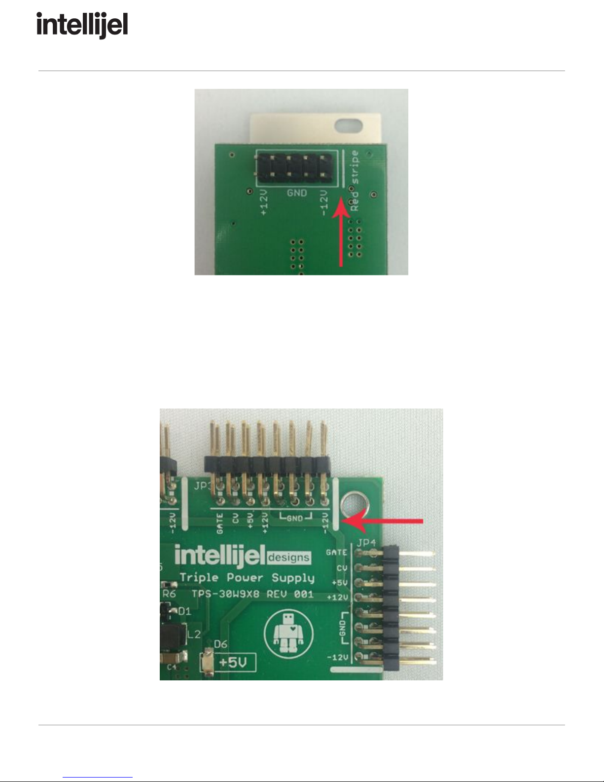
Ensure the 10-pin connector on the power cable is connected correctly to the module before
proceeding. The red stripe on the cable must line up with the -12V pins on the module’s power
connector. The pins are indicated with the label -12V, a white stripe next to the connector, the
words “red stripe”, or some combination of those indicators.
Page 3
Page 5
Audio Interface II Manual
Most modules will come with the cable already connected but it is good to double check the
orientation. Be aware that some modules may have headers that serve other purposes so
ensure the cable is connected to the right one.
The other end of the cable, with a 16-pin connector, connects to the power bus board of your
Eurorack case. Ensure the red stripe on the cable lines up with the -12V pins on the bus board.
On Intellijel power supplies the pins are labelled with the label “-12V” and a thick white stripe:
Page 4
Page 6

Audio Interface II Manual
If you are using another manufacturer’s power supply, check their documentation for
instructions.
Once connected, the cabling between a module and power supply should resemble the picture
below:
Before reconnecting power and turning on your modular system, double check that the ribbon
cable is fully seated on both ends and that all the pins are correctly aligned. If the pins are
misaligned in any direction or the ribbon is backwards you can cause damage to your module,
power supply, or other modules.
After you have confirmed all the connections, you can reconnect the power cable and turn on
your modular system. You should immediately check that all your modules have powered on
and are functioning correctly. If you notice any anomalies, turn your system off right away and
check your cabling again for mistakes.
Page 5
Page 7
Audio Interface II Manual
Front Panel
Page 6
Page 8

Audio Interface II Manual
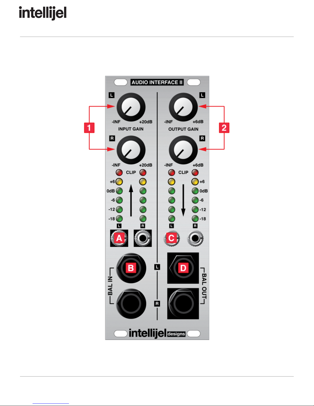
Controls
1. INPUT GAIN L/R
These knobs set the gain of the signal coming in to the modular via the BAL IN L/R
jacks. The knob range is from -∞ (no signal) to +6 dB. The signal levels are indicated on
the meters above the OUT L/R jacks.
2. OUTPUT GAIN L/R
These knobs set the gain of the signal leaving the modular via the BAL OUT L/R jacks.
The knob range is from -∞ (no signal) to +6 dB. The signal levels are indicated on the
meters above the IN L/R jacks.
Inputs & Outputs
A. OUT L/R
These jacks are the modular level outputs of the signals that come into the system via
the corresponding channel of the BAL IN L/R jacks. The signals are boosted to modular
levels according to the INPUT GAIN knobs.
B. BAL IN L/R
These jacks bring signals into your modular system from the outside world where they
are accessed from the corresponding OUT L/R jacks. Connect a 1/4″ balanced TRS
cable from the output of your other synthesizers, effects pedals, audio interfaces, etc. to
these jacks.
C. IN L/R
These jacks are the modular level inputs that send your modular’s audio to the outside
world. A modular audio signal connected to these jacks will appear at line level on the
corresponding BAL OUT jacks, with gain controlled by the OUTPUT GAIN knobs.
D. BAL OUT L/R
These jacks carry signals from your modular to your other audio equipment. Use a 1/4″
balanced TRS cable to connect each one to an input of an effects pedal, audio interface,
tape recorder, etc.
Page 7
Page 9

Audio Interface II Manual
Instruction
The Audio Interface II is divided into two halves that function independently. The left side is the
Input side which takes signals from line level sources such as sound cards, synthesizers, or
mixers, and converts them to modular level. The right side is the Output side and takes signals
from modular level sources and converts them to line level for sending to a sound card, mixer,
or other outboard processor. The diagram below illustrates a typical configuration for processing
audio from a synthesizer through the modular system and then passing the output to a mixer:
Input From an External Source
To take input from an external sound source and process it through the modular system first
connect the output of your external device to either the L or R BAL IN jack using a 1/4″ TRS
cable. If you are using a stereo source you may wish to connect to both the L and R BAL IN
jacks. You can also connect two totally different devices, one to L and the other to R.
The output from each channel of the BAL IN jacks will appear at the corresponding L or R
modular level output directly above the BAL IN jacks. You can adjust each input’s level using
the INPUT GAIN knobs. Ideally the knobs are set such that the loudest inputs cause the input
VU meters to go as high as possible without the red CLIP LED lighting up.
Page 8
Page 10
Audio Interface II Manual
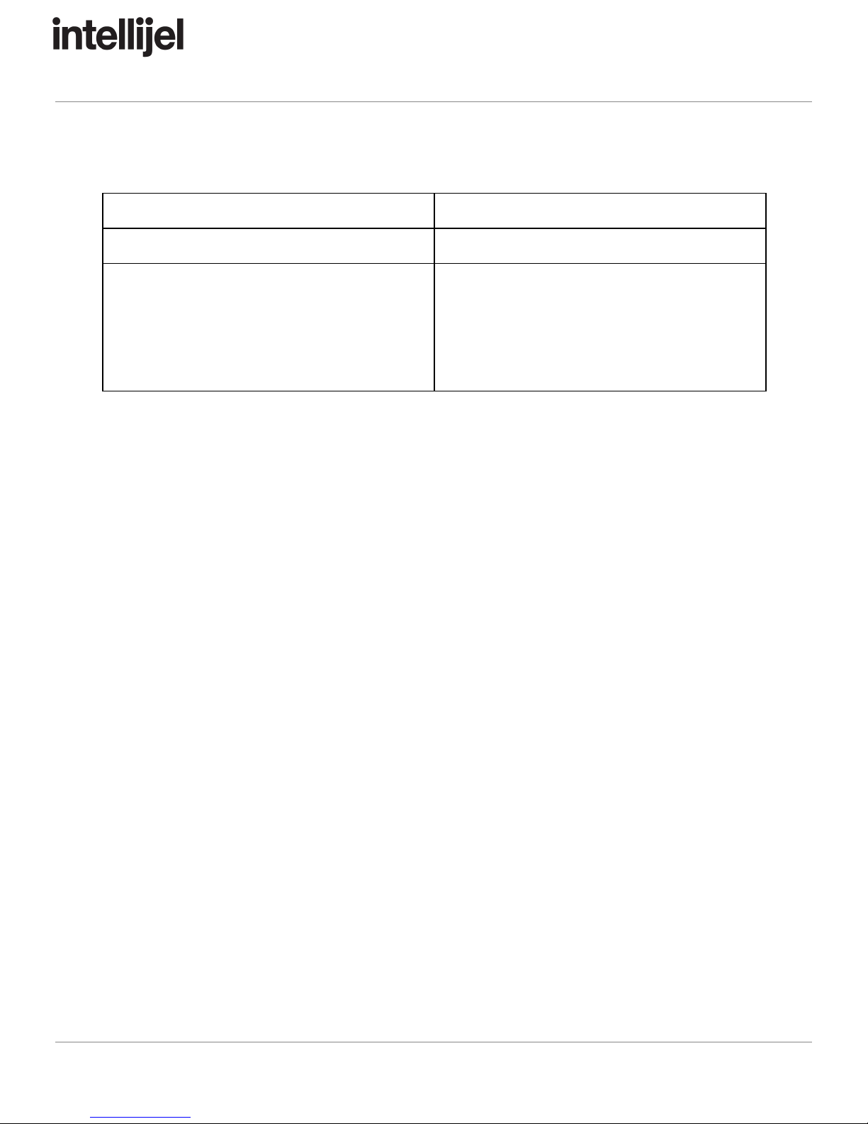
Technical Specifications
Width
10 hp
Maximum Depth
44 mm
Current Draw
50 mA @ +12V
50 mA @ -12V
NOTE: Nominal current draw is 50mA @ +12V,
but the current draw with all 24 LEDs lit is
120mA @ +12V
Page 9
 Loading...