

Page 1

ZT8101 Switch
User’s Manual
December 2001
Page 2

Information in this document is provided in connection with Intel® products. No license, express or implied, by estoppel or
otherwise, to any intellectual property rights is granted by this document. Except as provided in Intel’s T erms and Conditions of Sale
for such products, Intel assumes no liability whatsoever, and Intel disclaims any express or implied warranty, relating to sale and/or
use of Intel products including liability or warranties relating to fitness for a particular purpose, merchantability, or infringement of
any patent, copyright or other intellectual property right. Intel products are not intended for use in medical, life saving, or life
sustaining applications.
Intel may make changes to specifications and product descriptions at any time, without notice.
Designers must not rely on the absence or characteristics of any features or instructions marked “reserved” or “undefined.” Intel
reserves these for future definition and shall have no responsibility whatsoever for conflicts or incompatibilities arising from future
changes to them.
The ZT8101 may contain design defects or errors known as errata that may cause the product to deviate from published
specifications. Current characterized errata are available on request.
MPEG is an international standard for video compression/decompression promoted by ISO. Implementations of MPEG CODECs,
or MPEG enabled platforms may require licenses from various entities, including Intel Corporation.
This document and the software described in it are furnished under license and may only be used or copied in accordance with the
terms of the license. The information in this document is furnished for informational use only, is subject to change without notice,
and should not be construed as a commitment by Intel Corporation. Intel Corporation assumes no responsibility or liability for any
errors or inaccuracies that may appear in this document or any software that may be provided in association with this document.
Except as permitted by such license, no part of this document may be reproduced, stored in a retrieval system, or transmitted in
any form or by any means without the express written consent of Intel Corporation.
Contact your local Intel sales office or your distributor to obtain the latest specifications and before placing your product order.
Copies of documents which have an ordering number and are referenced in this document, or other I ntel literature may be obtaine d
by calling
1-800-548-4725 or by visiting Intel's website at http://www.intel.com.
*Other names and brands may be claimed as the property of others.
Copyright © 2001, Intel Corporation. All rights reserved.
Intel Corporation
5200 N.E. Elam Young Parkway
Hillsboro, Oregon 97124-6497
2 ZT8101 User’s Ma nual
Page 3

Contents
Contents
1 Introduction....................................................................................................................................9
Highlights..............................................................................................................................9
Ethernet Features.................................................................................................................9
Layer 2 Switching Functions....................................................................9
Layer 3 Switching Functions..................................................................10
Additional Features................................................................................................10
Front Panel Features .............................................................................10
Management Functions .........................................................................11
Warranty ................................................................................................11
Product Information and Sales Support..............................................................................11
2 Installation and Initial Setup.......................................................................................................13
Installing the Board............................ ...................................... ....... ...... ....... ...... ....... ..........13
Power on................................................................................................................14
Uninstalling the Board.........................................................................................................14
Identifying External Components....................................... ...... ....... ...... ....... ...... ....... ...... ....15
Status LEDs...........................................................................................................16
Health Status LED .................................................................................16
Hot Swap LED .......................................................................................16
Port LEDs ..............................................................................................................16
Link / Activity LED Mode........................................................................16
Link / Speed LED Mode.........................................................................17
Getting Started with Management ......................................................................................17
Accessing the Local Console.................................................................................17
To log in to the switch the first time........................................................18
Setting the IP Address ...........................................................................................18
To configure the IP address............................................ ...... ....... ...... ....18
Upgrading Firmware through Zmodem..................................................................19
To upgrade the firmware using Zmodem...............................................19
3 Switch Management and Operating Concepts.........................................................................21
Managing the Switch ..........................................................................................................21
Switch IP and MAC Addresses...........................................................................................22
Port Configurations.............................................................................................................22
Flow Control...........................................................................................22
Port Security and MAC Address Learning .............................................23
SNMP .................................................................................................................................23
BOOTP/DHCP Relay..........................................................................................................23
DNS Relay..........................................................................................................................24
Packet Forwarding...................................................... ....................................... ....... ...... ....24
MAC Address Aging Time .....................................................................................24
MAC Address Forwarding......................................................................................24
Storm Control.........................................................................................................25
Traffic Control ........................................................................................................25
IP Forwarding ........................................................................................................25
ARP Table..............................................................................................25
Router Ports.......... ...... ....... ...... ...... ....... ....................................... ...... ....26
ZT8101 User’s Manual 3
Page 4

Contents
Priority.................................................................................................................................26
Filtering...............................................................................................................................26
MAC Address Filtering...........................................................................27
IP Address Filtering................................................................................27
Port Mirroring......................................................................................................................27
Spanning Tree Protocol......................................................................................................28
STP Levels and Parameters..................................................................................28
STP Parameters for the Switch Level....................................................29
STP Parameters for the Port Level........................................................29
Link Aggregation.................................................................................................................30
VLANs.................................................................................................................................31
Static Port-Based VLANs.. ....... ...... ....................................... ...... ....... ...... ....... ...... .31
Static IEEE 802.1Q VLANs...... ...................................... ....... ...... ....... ...... ..............32
GVRP.....................................................................................................32
Ingress Checking ...................................................................................33
Broadcast Storm Control and VLANs ....................................................................33
Layer 3-Based VLANs ...... ....... ...................................... ....... ...... ....... ...... ..............34
Multi-Netting...........................................................................................................34
IP Interfaces........................................................................................................................34
System IP Interface................................................................................34
Additional IP Interfaces..........................................................................35
IP Addressing Scheme ..........................................................................35
Multicasting.........................................................................................................................36
Internet Group Management Protocol (IGMP).......................................................36
IGMP Queriers.......................................................................................................37
IGMP Snooping .....................................................................................................37
IGMP Group Settings.............................................................................................38
Routing Protocols ...............................................................................................................38
RIP.........................................................................................................................38
Distance Vector Multicast Routing Protocol (DVMRP) ..........................................38
Protocol-Independent Multicast - Dense Mode (PIM-DM).....................................39
4 Using the Telnet Console ...........................................................................................................41
Before You Start .................................................................................................................41
General Deployment Strategy . ...... ....... ...... ...... ....... ...... ....... ...... ...........................41
VLAN Layout..........................................................................................................42
IP Addressing Scheme for VLANs.........................................................................42
Static Route Assessment.. ....... ...... ....... ...... ...... ....... ....................................... ...... .42
Getting Started....................................................................................................................43
Console Usage Conventions.................................................................................43
Connecting to the Switch.......................................................................................43
To log in to the switch the first time........................................................44
Main Menu.............................................................................................................45
Creating User Accounts.........................................................................................46
To create a new user account................................................................46
Admin, User+ and Normal User Privileges ............................................47
To log in once you have created a registered user................................47
Saving Changes ....................................................................................................47
To save changes to NV-RAM ................................................................48
Reboot...................................................................................................................48
Basic Settings.....................................................................................................................48
4 ZT8101 User’s Ma nual
Page 5

Contents
Switch Information .................................................................................................49
Basic Switch Setup..................... ....... ...... ...... ....... ...... ....... ...... ....... ...... .................49
Network Management Setup .................................................................................51
To configure SNMP................................................................................51
To configure trap recipients ...................................................................51
To configure the access list .................. ...... ....... ...... ..............................52
Serial Port Settings ................................................................................................52
Port Configurations ................................................................................................52
Switch Utilities........................................................................................................53
To update firmware................................................................................54
To download a configuration file ............................................................54
To upload a configuration file.................................................................54
To upload a history log file.....................................................................54
To test connectivity with ping.................................................................55
BOOTP/DHCP Relay.............................................................................................55
To enable the BOOTP/DHCP relay agent .............................................55
DNS Relay.............................................................................................................56
To configure DNS Relay services...................... ...... ....... ...... ....... ...... ....56
Network Monitoring.............................................................................................................57
Port Statistics.........................................................................................................57
To view port utilization ...........................................................................57
To view port error statistics....................................................................58
To view an analysis of packet sizes and types ......................................59
Address Tables......................................................................................................59
To view the MAC address table.............................................................59
To view the IP address table..................................................................60
To view the routing table................ ....... ...... ....... ...... ....... .......................6 0
To view the ARP table ................................ ....... ...... ..............................61
Status.....................................................................................................................61
To view GVRP status.............................................................................61
To view the router ports ........... ...... ....... ...... ....... ...... ....... ...... ....... ..........61
To view the IGMP snooping status ....................................... .................62
To view the IP multicast forwarding table ..............................................62
To view the IGMP group table .................... ....... ...... ..............................6 2
To view the DVMRP routing table..........................................................63
To view the switch’s history log..............................................................63
Advanced Setup .................................................................................................................64
Spanning Tree .......................................................................................................64
To configure global STP switch settings................................................64
To define the port members of an STP group........................................65
Forwarding.............................................................................................................66
To configure MAC address aging ..........................................................66
To configure unicast MAC address forwarding......................................67
To configure multicast MAC address forwarding ...................................67
To configure storm control .....................................................................68
To configure advanced traffic control.....................................................68
To configure static IP routes ..................................................................69
To configure static ARP.........................................................................69
IP Address Filtering ...............................................................................................69
To specify an IP address for filtering......................................................69
MAC Address Priority ............................................................................................70
Mirroring Configurations ........................................................................................71
ZT8101 User’s Manual 5
Page 6

Contents
To configure a port for mirroring ............................................................71
VLAN Configuration...............................................................................................71
To configure GVRP globally...................................................................71
To create or modify a port-based VLAN ................................................72
To create or modify an 802.1Q VLAN....................................................72
To configure the member ports of an 802.1Q VLAN..............................73
Link Aggregation....................................................................................................74
To configure a link aggregation group ...................................................74
Layer 3 IP Networking ........................................................................................................74
Setting Up IP Interfaces.........................................................................................75
To set up IP Interfaces on the switch.....................................................75
RIP Configuration ..................................................................................................75
To configure RIP....................................................................................75
Multicast Global Configurations.............................................................................76
To configure globally the multicast protocols.........................................76
IGMP Configuration ...............................................................................................77
To configure IGMP snooping.................................................................77
To configure IGMP for an IP interface ...................................................78
DVMRP Interface Configuration ............................................................................78
To configure DVMRP for an IP interface................................................78
PIM-DM Interface Configurations .. ....... ...... ...... ....... ...... ....... ...... ...........................79
To configure PIM-DM for an IP interface ...............................................79
Static Router Port .......................... ....... ...... ...... ....... ...... ....... .................................79
To configure a static router port.............................................................80
5 Using the Web Console .............................................................................................................81
Before You Start .................................................................................................................81
General Deployment Strategy . ...... ....... ...... ...... ....... ...... ....... ...... ...........................81
VLAN Layout..........................................................................................................82
IP Addressing Scheme for VLANs.........................................................................82
Static Route Assessment.. ....... ...... ....... ...... ...... ....... ....................................... ...... .82
Getting Started....................................................................................................................83
Logging In............................................. ...... ...... ....... ...... ....... ...... ....... ...... ....... ...... .83
Configuration Options.................... ....... ...... ...... ....... ...... ....... ...... ....... ...... ..............84
User Accounts .......................................................................................................85
Admin and User Privileges.....................................................................85
Saving Changes ....................................................................................................86
To retain any configuration changes permanently.................................86
Restart...................................................................................................................87
Factory Reset ........................................................................................................87
To reset the switch to factory default values..........................................87
Basic Settings.....................................................................................................................87
Switch Information ...... ...... ....... ...................................... ....... ...... ....... ...... ....... .......88
Basic Switch Setup................................................................................................88
Serial Port Settings................................................................................................90
Port Configurations................................................................................................90
Network Management............................................................................................90
To configure SNMP community strings..................................................91
To configure trap recipients ...................................................................91
To configure management station IP addresses ...................................92
Switch Utilities ...... ....... ...... ....... ...... ....... ...... ...... ....................................... ....... ...... .92
6 ZT8101 User’s Ma nual
Page 7

Contents
To update firmware................................................................................92
To download a configuration file ............................................................93
To upload a configuration file.................................................................93
To upload a history log file.....................................................................93
To test connectivity with ping.................................................................94
BOOTP/DHCP Relay Agent ..................................................................................94
To configure the BOOTP/DHCP relay agent .........................................94
To configure the static BOOTP relay setup ...........................................95
DNS Relay.............................................................................................................95
To configure DNS Relay .... ...... ...... ....... ...... ....... ....................................96
To configure the static DNS table ..........................................................96
Network Monitoring.............................................................................................................96
Port Statistics.........................................................................................................97
To view port utilization ...........................................................................97
To view port error statistics....................................................................97
To view an analysis of packet sizes and types ......................................98
Address Tables......................................................................................................99
To view the MAC address table.............................................................99
To view the IP address table..................................................................99
To view the routing table................ ....... ...... ....... ...... ....... .....................10 0
To view the ARP table ................................ ....................................... ..100
Status...................................................................................................................101
To view GVRP Status ..........................................................................101
To view router ports .............................................................................101
To view IGMP snooping status ............................................. ....... ........102
To view the IP multicast forwarding table ............................................102
To view the IGMP group table .................... ....... ...... ............................10 2
To view the DVMRP routing table........................................................103
To view the switch’s history log............................................................103
Advanced Setup ...............................................................................................................104
Spanning Tree Protocol .......................................................................................104
To configure STP switch settings.........................................................104
To define the port members of an STP group......................................106
Forwarding...........................................................................................................106
To configure MAC address aging ........................................................107
To configure unicast MAC address forwarding....................................107
To configure multicast MAC address forwarding .................................107
To configure storm control ...................................................................108
To configure advanced traffic control...................................................108
To configure static IP routes ................................................................109
To configure static ARP.......................................................................109
IP Address Filtering .............................................................................................110
To specify an IP address for filtering....................................................110
MAC Address Priority ..........................................................................................110
To set up a MAC address priority ........................................................110
Mirroring Configurations ......................................................................................111
To configure a port for mirroring ..........................................................111
VLAN Configurations ......................... ...... ...... ....... ...... ....... ...... ....... ...... ....... ........112
To configure GVRP globally.................................................................112
To configure a port-based VLAN .........................................................112
To configure an 802.1Q VLAN.............................................................112
To configure member ports of an 802.1Q VLAN..................................113
ZT8101 User’s Manual 7
Page 8

Contents
Link Aggregation..................................................................................................113
To configure a link aggregation group .................................................114
Layer 3 - IP Networking ....................................................................................................114
Setting Up IP Interfaces.......................................................................................114
To set up IP interfaces on the switch...................................................114
RIP Configuration ................................................................................................115
To globally enable or disable RIP........................................................115
To configure RIP interface settings......................................................115
Multicast Global Configurations...........................................................................116
To configure globally the multicast protocols.......................................116
IGMP Configurations ...........................................................................................117
To configure IGMP snooping...............................................................117
To configure IGMP for an IP interface .................................................118
DVMRP Interface Configurations.........................................................................118
To configure DVMRP for an IP interface..............................................118
PIM-DM Setup ............ ...... ....... ...... ....... ...................................... ....... ...... ....... .....119
To configure PIM-DM for an IP interface .............................................119
Static Router Port Settings ............ ....... ...... ...... ....... ...... ....... ...... ....... ..................119
To configure a static router port...........................................................120
A Agency Approvals.....................................................................................................................121
CE Certification....................................................................................121
Safety...................................................................................................121
Emissions Test Regulations.................................................................121
Regulatory Information .....................................................................................................122
FCC—Federal Communications Commission (USA) ..........................122
Industry Canada (Canada)...................................................................122
Product Safety Information...............................................................................................123
Safety Precautions...............................................................................123
Product Safety Information...............................................................................................124
AC and/or DC Power Safety Warning (AC and/or DC Powered Units)124
Rack Mount Enclosure Safety..............................................................124
Revision History
Date Revision Description
December 6, 2001 00.2 Made technical corrections.
November 14, 2001 00.1a Added agency approvals.
November 9, 2001 00.1 First draft.
8 ZT8101 User’s Ma nual
Page 9

Introduction 1
The ZT8101 board is a high performance managed switch that supports both Layer 2 and Layer 3
features. For fast connection speeds and flexibility, it has 24 10/100 Mbps Fast Ethernet ports and 2
gigabit Ethernet ports in a 6U CompactPCI* form factor board. The in-chassis switch minimizes
external wiring and needs no extra rack height, thus improving density and reliability.
You can manage the switch from a termi nal, with Teln et, from a Web bro wser, or through IPMI via
the Chassis Management Module (ZT7101). The ZT8101 routes and switches at full wire speed
with its non-blocking architecture, and it has sophisticated multicast protocol s to limit unnecessary
traffic. It provides an in-chassis switch fabric that you can configure to operate in a redundant
configuration.
Highlights
• Full wire speed on all ports
• VLAN ID tagging and priority queues
• Port aggregation
• Port mirroring
• Packet filtering
• Multicast and broadcast storm control
• DHCP/BOOTP packet forwarding
• RIP (v1 and v2), DVMRP, PIM-DM
• Low port latency
• Hot-swappable board with LED indicator
Ethernet Features
Layer 2 Switching Functions
• 10BASE-T, 100BASE-TX, and 1000BASE-T port functions
— 22 10/100 Fast Ethernet ports to the mid-plane connectors
— 2 10/100 Fast Ethernet ports (RJ45) on the font panel
— 2 100/1000 Ethernet ports (RJ45) on the front panel
• Auto-negotiation function for speed (10 MB/100 MB/1000 MB), duplex (full/half), and flow-
control
• Back pressure flow control for half-duplex mode
• IEEE 802.3x compliant flow control for full-duplex mode
ZT8101 User’s Manual 9
Page 10

Introduction
• Per device packet buffer: 512 KB
• 8.8 Gbps switching fabric capacity
• Store and forward switching forwarding mode
• 8 KB Layer 2 MAC address
• Broadcast and multicast storm control
• Port mirroring
• Port aggregation
• IEEE 802.1D Spanning Tree Protocol
• IEEE 802.1Q tagged VLANs
• GVRP (GARP VLAN Registration Protocol) for automatic VLAN configuration
• IEEE 802.1p priority support with 4 priority queues
• IGMP Snooping with broadcast control
Layer 3 Switching Functions
•
Wire speed IP forwarding rate per system
• Hardware-based Layer 3 IP switching
• 2 KB Layer 3 IP address entries
• RIP (Routing Information Protocol) v1 and v2
• IP v4
• IGMP (Internet Group Management Protocol) v2
• PIM-DM (Protocol Independent Multicast-Dense Mode)
• DVMRP (Distance Vector Multicas t Rout ing Protocol) v3
• IP multi-netting
• IP fragmentation
• Path MTU discovery
• IEEE 802.1D frame support
• DHCP/BOOTP relay
Additional Features
Front Panel Features
• 2 10/100 RJ45 ports
• 2 100/1000 RJ45 ports
• RS 232 serial console port
• Status LEDs for port link, speed, and activity
10 ZT8101 User’s Manual
Page 11

Management Functions
• RS-232 port for out-of-band management and system diagnostics
• Telnet remote control console
• Web-based management console
• SNMP v1 Agent
• Supported MIBs
— MIB-II
— Bridge MIB
— RMON MIB (Statistics, History, Alarm, Event)
— RIP MIB
— CIDR MIB
— 802.1p MIB
• TFTP
• IP filtering on management interface
• DHCP client
• Password enabled
Introduction
Warranty
2 years
Product Information and Sales Support
Tel. (805) 541-0488
www.Intel.com
ZiatechInfo@Intel.com
ZT8101 User’s Manual 11
Page 12

Introduction
12 ZT8101 User’s Manual
Page 13
Installation and Initial Setup 2
This chapter provides installation and initial setup information for the switch .
Installing the Board
These instructions explain the mechanical aspects of installing a ZT8101board. The board should
be installed in a PICMG* 2.16 compliant fabric slot.
1. System power does not need to be off to insert a ZT8101 board.
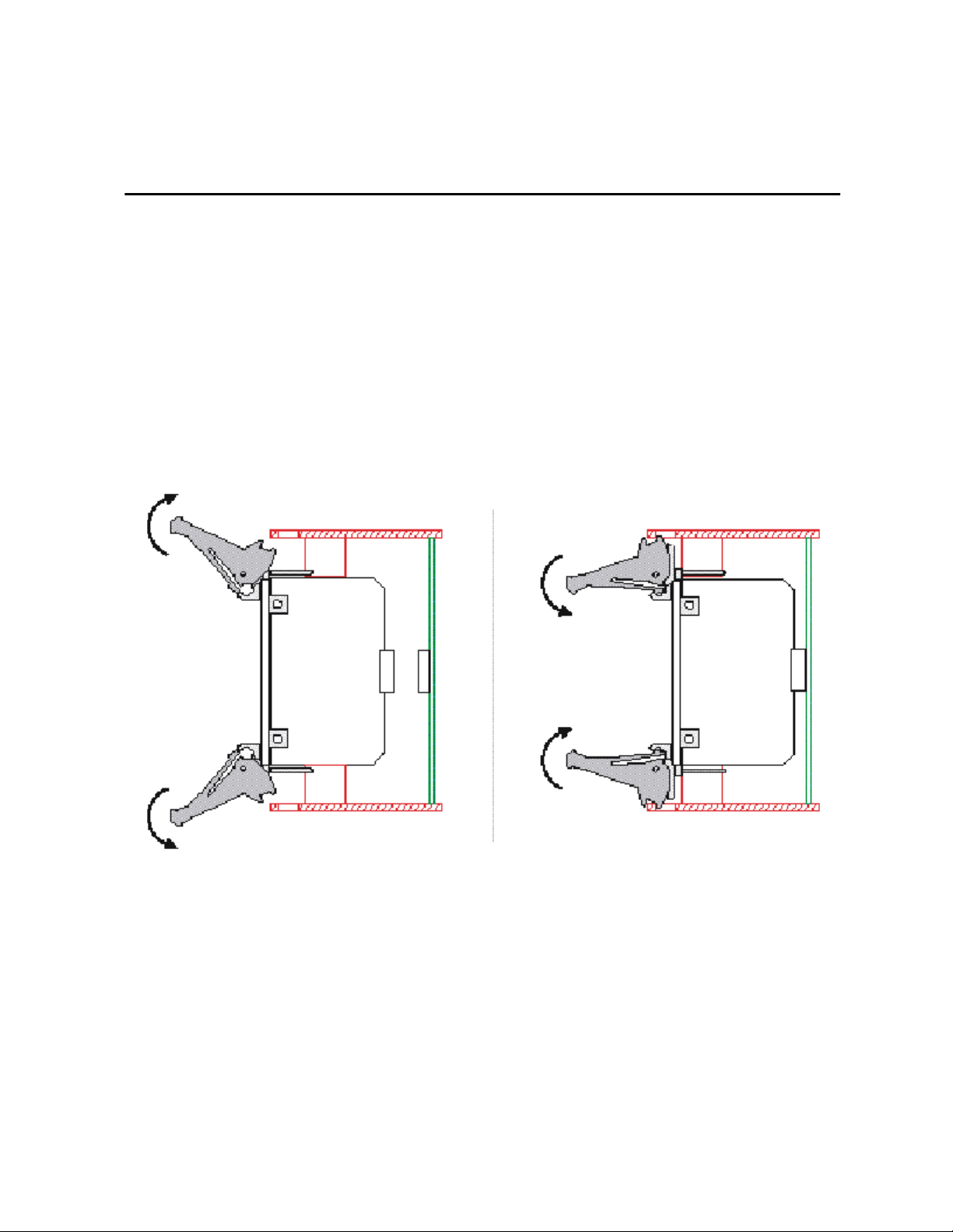
2. Prepare the board by opening the injector/ejector mechanisms.
Injector/Ejector Operation s
Open
Closed
3. Carefully align the edges of the board with the left and right card guides in the appropriate slot.
It may be helpful to look into the enclosure to verify correct alignment of the rails in the
guides.
4. Taking care to keep the board aligned in the guides, slide the board in until the injector/ejector
mechanisms engage the retention bars.
5. Simultaneously push in the board and rotate the injector/ejector mechanisms to their closed
positions (rotate inward) to seat the backplane connectors. When the board is in place, it will
boot if the system power is on.
6. Make the desired connections at the faceplate and configure the board.
ZT8101 User’s Manual 13
Page 14

Installation and Initial Setup
Power on
After the power switch is turned on, the LED indicators should respond as follows:
• All LED indicators will momentarily blink, which represents a reset of the system.
• The board status LED indicator will blink while the switch loads onboard software and
performs a self-test. After approximately 20 seconds, the LED will light again to indicate the
switch is in a ready state.
• The hot-swap LED indicator will be off.
• The port LED indicators will be off if there is no Ethernet connection and on if there is an
Ethernet connection.
Uninstalling the Board
These instructions explain the mechanical aspects of removing a ZT8101 board from a system.
1. You do not need to turn off the system power to remove a ZT8101 board.
2. Disconnect connections at the faceplate (Ethernet and serial ports).
3. The board should be in a “safe” state to be removed or data may be lost. Signal the system that
a board is about to be remo ved by parti ally unlatchin g the ejectors on the board to be remov ed.
Do not fully open the ejectors, as this levers the board out of the enclosure and prematurely
breaks its backplane connection.
4. Wait for the blue hot swap LED on the board's faceplate to light; this indicates that board
processes have finished and the board is safe to extract. If the hot swap LED fails to light after
30 seconds, re-latch the ejectors and unlatch them again. In this case, the board is safe to
extract (though the hot swap LED may not light).
5. Once the hot swap LED lights, open the injector/ejector mechanisms fully, rotating the handles
outward until the board disengages from the backplane (refer to “Injector/Ejector Operations”
on page 13).
6. Slide the board evenly out of the enclosure.
7. Install a replacement board or cover the empty slot with a filler panel to maintain the
enclosure's shielding and cooling performance.
14 ZT8101 User’s Manual
Page 15
Identifying External Components
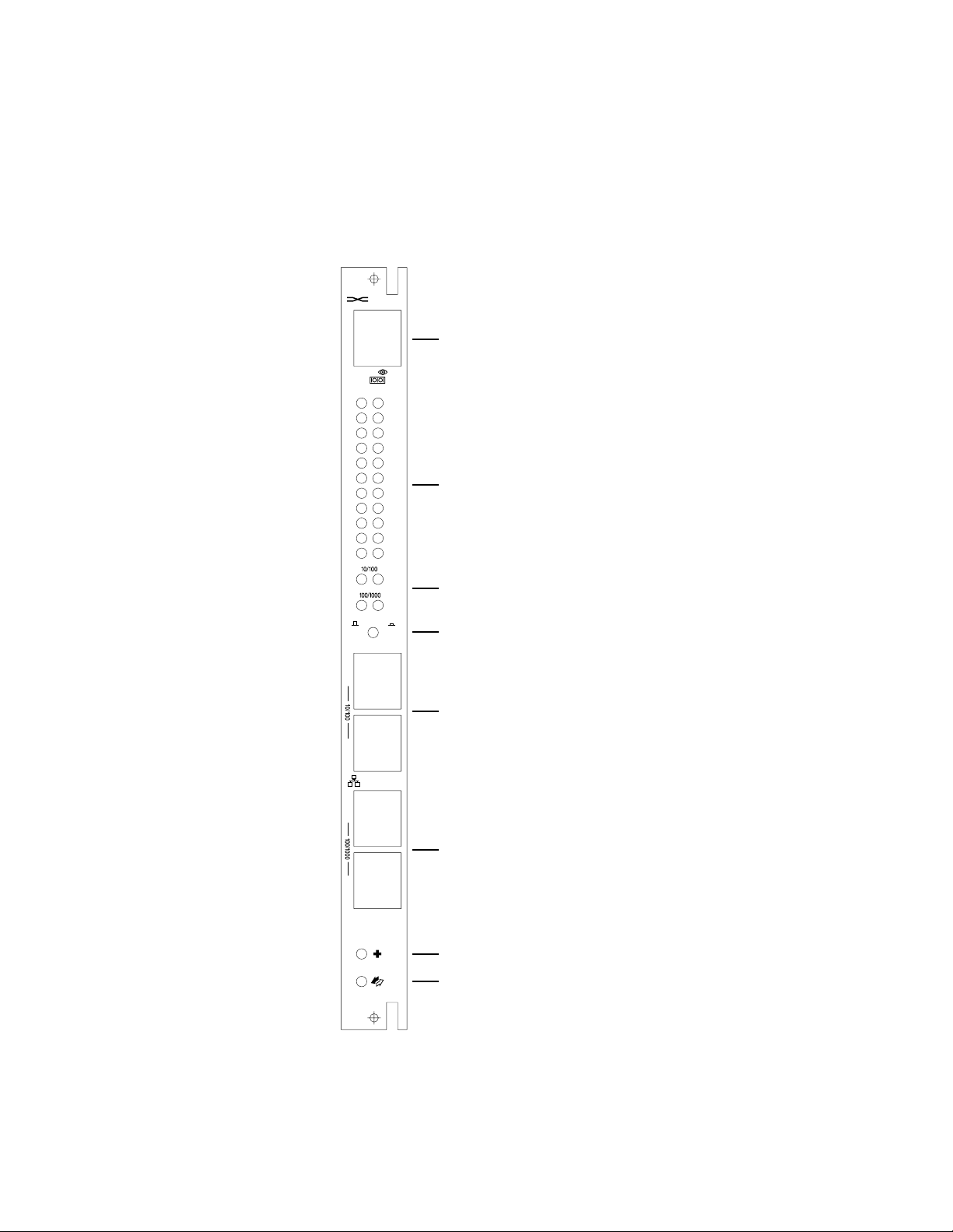
This chapter describes the front panel and the LED indicators of the ZT-8101switch. The front
panel consists of LED indicators, a management serial port, a toggle button, two 10/100 Ethernet
ports, and two 100/1000 Ethernet ports.
Management Serial Port
12
34
56
78
910
11 12
13 14
15 16
17 18
19 20
21 22/f
23 24
26
25
Ethernet Channel LEDs
(Activity/Speed)
Front Panel Ethernet Port LEDs
(Activity/Speed)
Installation and Initial Setup
LINK
ACT
23
24
25
26
STATUS
HOT SWAP
SPEED
Toggle Activity/Speed LEDs Pushbutton
10/100 Ethernet Ports
100/1000 Ethernet Ports
Board Status
Hot Swap
ZT8101 User’s Manual 15
Page 16

Installation and Initial Setup
Status LEDs
The two LEDs at the bottom of the font panel are status LEDs. The top LED indicates the overall
status of the board and the bottom LED indicates the hot swap status of the board.
Health Status LED
Status Meaning
Off Not powered.
Green Powered and functioning normally.
Amber
Hot Swap LED
Status Meaning
Off Switch is active or in the process of shutting down; do not remove it.
Blue Safe to remo ve th e sw i tch.
Attention needed due to one of the following conditions:
• Over temperature
• Backend supplies exceeding voltage limits
• IPMB time outs
Port LEDs
The LED array on the front panel displays inf ormati on abou t all the Ethe rnet l inks on t he bo ard. A
green/amber two-color LED is used for each of the 26 Ethernet port connections (24 10/100 + 2
Gigabit). A push-button switch just below the array toggles th e LED display from Link /Activity
mode to Link / Speed mode. The default LED mode is Link /Activity. When you depress the switch
button, the LEDs are in Link/Speed mode.
Link / Activity LED Mode
Status Meaning
Off No Ethernet connection.
Solid Green Good connection, link present.
Blinking Green Port is transmitting or receiving packets (activity is on going).
Port is not forwarding packets. The port has been disabled by management, an
address violation has occurred, or the port is being blocked by STP.
Solid Amber
Note: After a port is reconfigured, the port LED can remain amber for as long as
30 seconds while STP checks the switch for loop paths. When the STP checking
is completed, the port then resumes displaying its current connection status.
16 ZT8101 User’s Manual
Page 17

Link / Speed LED Mode
Port Type Status Meaning
10/100 Off 10 Mb/s
Solid Green 100 Mb/s
100/1000 Solid Green 100 Mb/s
Solid Amber 1000 Mb/s
Getting Started with Management
The switch contains the following components:
• A CPU
• Memory for data storage
• Flash memory for configuration data, operational programs, and SNMP agent firmware.
These components allow you to manage and monitor the switch from either the board’s serial port
or the network itself. You can configure and manage the switch from these locations:
Installation and Initial Setup
• A terminal or a workstation running terminal emulation software and connected to the switch
via the RS-232 port.
• A workstation connected to the network and running Telnet.
• A workstation connected to the network and running a Web browser.
To access the switch via Telnet or a Web browser, you must assign the switch an appropriate IP
address for your network. To do this, you must access the switch using the RS-232 port via the
Local Console.
This section explains how to
• Set up access to the Local Console
• Configure the switch’s IP address
Once you complete these tasks, you can access the switch from any of the three locations. Since the
Local Console and the Telnet Console use the same interface, chapter 4 explains how to access the
switch using Telnet and then explains all the configuration and management options in this
interface. Chapter 5 explains the Web Console. Both the Web and the Telnet/Serial interfaces
expose the same functionality. Chapter 3 describes some basic concepts that you should be familiar
with before configuring the switch.
Accessing the Local Console
The Local Console is a terminal or a workstation running a terminal emulation program that is
connected directly to the switch via the RS-232 console port on the front of the switch. Such a
connection is referred to as an “Out-of-Band” connection because the console is connected to the
switch using a different circuit than the circuit used for normal network communications. The
Local Console can be used to set up and manage the switch even when the network is down.
ZT8101 User’s Manual 17
Page 18

Installation and Initial Setup
The serial port on the front panel uses Cisco* cable kit (Order Number: ACS-DSBUASYN). This
kit includes a DB25 terminal adapter, a DB-9 terminal adapter, and RJ-45 rollover cable.
A terminal (such as a VT-100) or a computer running a terminal emulation program (such as
HyperTerminal, which is automatically installed with Windows*) is connected to this cable.
The serial port is set at the factory for the following configuration:
• Baud rate: 9600
• Data width: 8 bits
• Parity: None
• Stop bits: 1
• Flow Control: None
Make sure the terminal or computer you are using to make this connection is configured to match
these settings.
If you are having problems making this connection on a computer, make sure the emulation is set
to VT-100. If you still don’t see anything, press CTRL+R to refresh the screen.
To log in to the switch the first time
The usernames and passwords used to access the switch are case sensitive; therefore, “S” is not the
same as “s.”
When you first connect to the switch, you will be presented with a login screen.
1. Use the Arrow keys or the Tab key to move to the Username field. Leave the field blank and
press Enter. There is no initial username.
2. Move to the Password field. Leave the field blank and press Enter. There is no initial
password. The Main Menu appears.
The first created user automatically gets administrator privileges. One of your first configuration
tasks should be to create at least one Admin-level user for the switch to protect it from
unauthorized users.
Press CTRL+R to refresh the screen. This command can be used at any time to force the console
program in the switch to refresh the console screen.
Setting the IP Address
You use the Basic Network Setup menu to set the boot-up operation for obtaining an IP address or
to manually assign the IP address for the switch. The switch needs a valid IP address for your
network to access the switch via Telnet or the Web.
To configure the IP address
1. From the Main Menu, select Basic Network Setup and press Enter.
18 ZT8101 User’s Manual
Page 19

Installation and Initial Setup
2. To configure the IP address, use the Arrow keys or the Tab key to modify the settings in the
New Switch IP Settings column.
Parameter Default Description
Get IP From Manual
IP Address 10.90.90.90 Specifies the IP address assigned to the switch.
Subnet Mask 255.0.0.0
Default Gateway 0.0.0.0
VLAN Name default
Specifies the method for assigning the switch an IP address.
Use the spacebar to toggle to Manual, DHCP, or BOOTP.
Specifies the subnet mask assigned to the switch and to the
other devices on this segment of the network.
Specifies the IP address of the device that routes to different
networks. A gateway must be defined if the workstation you
are going to use for switch management is located on a
different IP segment than the switch.
Specifies the name of the VLAN that contains the
workstations that you will use to manage the switch. This
VLAN must already exist.
3. To configure a name and contact information for the switch, enter information in the following
fields.
Parameter Description
Name
Location Specifies the physical location of the switch.
Contact Specifies the name of the person responsible for the switch.
Specifies the name assigned to the switch. If you are installing multiple
switches, you should give each a unique name.
4. Highlight APPLY and press Enter.
5. Press Escape to return to the Main Menu.
6. To save your changes to NV-RAM, highlight Save Changes and press Enter .
To continue configuring the switch, see chapter 4 for information on this interface. See chapter 5
for information about using the Web Console.
Upgrading Firmware through Zmodem
Generally, TFTP is the first choice to use to upgrade firmware. The Telnet Console and the Web
Console both have options for upgrad i ng the fi rmware us i ng a TFT P ser ver (see chapt ers 4 and 5).
However, you can also use Zmodem to upgrade the firmware from the serial port.
Note: If FLASH becomes corrupted because you lose power when upgrading the firmware, you must use
Zmodem to fix the problem.
To upgrade the firmware using Zmodem
1. Obtain the runtime firmware.
2. Using Windows HyperTerminal*, log in to the switch through the serial port.
3. From the Main Menu, select Reboot and press Enter.
ZT8101 User’s Manual 19
Page 20

Installation and Initial Setup
4. When the power on self test message appears, press the # key and wait for the following
message:
Please change your baud rate to 115200 for the Zmodem upgrade, or
press CTRL+C to go to the BOOT Menu.
If you press CTRL+C, you can configure the baud rate to a different value.
5. Change HyperTerminal’s baud rate to match the target’s setting.
6. Use t he Send File function of HyperTerminal to upgrade the firmware.
When the download is completed, Zmodem will display a message indicating that it is done
and then a message about loading the Runtime image.
7. Change the baud rate of HyperTerminal back to 9600 bps.
8. Disconnect and reconnect.
9. Log in to the switch.
10. From the main menu, select Switch Information and press Enter. Verify the firmware
version.
20 ZT8101 User’s Manual
Page 21

Switch Management and Operating
Concepts 3
This chapter describes many of the concepts you need to understand to configure and manage the
switch. It also describes many of the features available for managing the switch. The instructions
for configuring the switch are in chapter 4 (Telnet Console) and chapter 5 (Web Console).
Managing the Switch
The ZT8101 switch has th ree methods for configurin g switch p arameters and vi ewing switch status
and statistics:
• Serial—The switch’s serial port on the front panel allows a terminal or a PC running terminal
emulation software to be connected to the switch and configure the switch. It uses the same
application that is used over Telnet. The serial port is usually used only for initial set up, such
as configuring the switch’s IP address, or when the network is down. It can also be used to
upgrade the switch’s firmware with Zmodem.
• Telnet—The switch's embedded Telnet server allows users from remote systems, which are
running a Telnet application over TCP/IP, to log in to the switch, configure it, and view the
status of and statistics from the ports. The current implementation allow eight 8 Telnet sessions
to be active at the same time.
• Web—The switch's embedded Web server allows users from remote systems, which are
running a Web browser, to log in to the switch, configure it, and view the status of and
statistics from the ports. The current implementation allows five HTTP sessions to be active at
the same time.
The switch also contains the following utilities:
• Ping—The Ping utility invokes the ICMP echo request and echo reply messages. A host or
gateway sends an ICMP echo request message to a specified destination. Any computer that
receives an echo request formulates an echo reply and transmits it to the original sender. The
echo request and associated reply can be used to test whether a destination is reachable and
responding. Five ping sessions can be supported simultaneously.
• TFTP—This protocol is used to transfer files without any kind of authentication. It runs on
top of UDP, using timeout and retransmission to ensure that data arrives. The switch's TFTP
client allows users to copy files from and to a remote system that is running the TFTP server
protocol. The TFTP client allows only one user to access it and transfer files.
You can use the TFTP client to do the follo wing:
— Download firmware.
— Download or upload a switch configuration file.
— Upload the switch's history log.
Some TFTP servers cannot determine when a transaction is aborted. In these cases, you must
reboot the switch, which restarts the TFTP server and re-initializes the TFTP transaction.
ZT8101 User’s Manual 21
Page 22

Switch Management and Operating Concepts
• Switch diag nost ics —The PROM loader automatically runs memory diagno stics each time the
switch is booted.
• Reset to factory defaults—The switch includes an option that allows you to reset the
configuration to the factory defaults. You can select to reset the IP address or save your
configured IP address.
Switch IP and MAC Addresses
Each switch must be assigned its own IP Address. The switch's default IP address is 10.90.90.90.
You can change the default switch IP address to meet the specification of your networking address
scheme.
The switch is also assigned a unique MAC address by the factory. You cannot change this MAC
address.
In addition, you can also set an IP address for a gateway router. This becomes necessary when the
network management station is located on a different IP network from the switch, making it
necessary for management packets to go through a router to reach the network manager, and vice
versa.
For security, you can list the IP addresses of the network management stations that you want to
manage the switch. If you list IP addresses, only those workstations have access; all others will be
denied.
You can also configure a VLAN for the network that the management stations are on, and then
configure the switch for this VLAN.
Port Configurations
By default, the switch is configured to use auto-negotiation to determine each port's speed and
duplex setting. The user can modify this and configure a port to use a specified configuration. The
Ethernet ports have the following characteristics:
Ethernet Por t Link Speed Duplex
Fast Ethernet (10/100) 10/100 Mbps Half, Full
Gigabit Ethernet 100/1000 Mbps Full
Flow Control
All ports have a traffic limit because they have a limited buffer space to receive incoming frames.
Upon reaching the limit, a port either starts dropping packets or triggers fl ow contr ol. The ZT8101
switch uses the following methods for flow control:
• 802.3x flow control—The switch sends PAUSE frames, which request remote ports to delay
sending packets for a period of time. Sending ports suspend further frame transmission until
the specified time period has elapsed.
• 802.3x compliant flow control —The switch does not send PAUSE frames, but it does
respond to them.
22 ZT8101 User’s Manual
Page 23

Switch Management and Operating Concepts
• Back pressure—The switch fakes a collision and then transmits a jam sequence to ensure all
stations are notified of the “collision.” This causes the sending ports to trigger their back-off
routines and reduces the amount of traffic on the port.
The port type and duplex mode determine which type of flow control is used. The following table
lists the port types and their flow control methods.
Port Type Duplex Mode Flow Control
Fast Ethernet (10/100) Half Back pressure
Fast Ethernet (10/100) Full 802.3x compliant
Gigabit Ethernet Full 802.3x
Port Security and MAC Address Learning
For security purposes, you can disable MAC address learning on one or more ports. When MAC
address learning is disabled, a port cannot discover MAC addresses. The port receives only
broadcast traffic and packets with destination MAC addresses that match the port's MAC address.
The default value for each port is learning enabled.
SNMP
The switch has an embedded Simple Network Management Protocol (SNMP) agent which is
compliant with SNMPv1. This agent monitors the status of the board’s hardware and the traffic
passing through its ports. A computer attached to the network, called a management station, can
access this information. The switch uses the following features to control access to its information:
• Community strings—You can configu re up to four comm unity strings so that on ly authorized
management stations can access the agent. You can set each string to grant either read only or
read/write access.
• IP address—You can restrict access to specified IP addresses. You can enter up to three IP
addresses which restricts access to these specified management stations.
You can also specify which management agents receive the trap messages generated by the SNMP
agent. These trap messages are status messages that alert you of events such as authentication
failure, STP topology changes, and link status changes on the port.
BOOTP/DHCP Relay
BOOTP and DHCP allow stations to obtain boot and TCP/IP information dynamically. The relay
agent allows them to obtain this information when the BOOTP/DHCP server is not on the same IP
interface as the end station. You can configure the switch so that the messages are forwarded from
one interface to the appropriate server on another interface.
ZT8101 User’s Manual 23
Page 24

Switch Management and Operating Concepts
DNS Relay
The Domain Name System (DNS) is used to map names to IP addresses. DNS relay enables the
switch to act as a DNS cache or proxy. It forwards DNS requests to DNS servers only if it can’t
resolve the name from its cache.
If you enable DNS relay on the switch, you can specify a primary and secondary DNS server to
forward requests that the switch cannot resolve. You can also specify that requests destined for
specific DNS servers should be first serviced by looking in the switch’s table.
Packet Forwarding
The switch maintains a forwarding table. This table contains the relationship between a destination
MAC or IP addresses and the Ethernet port or gateway router the destination resides on. This
information is then used to forward packets. This reduces the traffic congestion on the network,
because packets, instead of being transmitted to all ports, are transmitted to the destination port
only. For example, if Port 1 receives a packet destined for a station on Port 2, the switch transmits
that packet through Port 2 only, and transmits nothing through the other ports. This process is
referred to as “learning” the network topology.
You can configure forwarding rules for the following:
• MAC address aging
• MAC address forwarding
• IP address to a specified gateway
• IP address to a specified MAC address
MAC Address Aging Time
The aging time affects the lea rning p roces s of the switch. Dynamic forwarding table entries, which
are made up of the source and destination MAC addresses and their associated port numbers, are
deleted from the table if they are not accessed within the aging time.
The aging time can be 10 — 1,000,000 seconds with a default value of 300 seconds. A very long
aging time can result in dynamic forwarding table entries that are out-of-date or no longer exist.
This may cause incorrect packet forwarding decisions by the switch.
If the aging time is too short, however, many entries may be aged out too soon. This will result in a
high percentage of received packets whose source addresses cannot be found in the forwarding
table, in which case the switch will broadcast the packet to all ports, negating many of the benefits
of having a switch.
Static forwarding entries are not affected by the aging time.
MAC Address Forwarding
The switch allows you to configure how unicast and multicast packets are forwarded.
24 ZT8101 User’s Manual
Page 25

• For unicast packets, you specify the MAC address and then either select the port that they will
be forwarded to or have them dropped (called “BlackHole”).
• For multicast packets, you specify the MAC address and then select the ports they can be
forwarded to.
Storm Control
You can also set th res hold s to contr ol broadcast and multicast storms. When the threshold is
exceeded, the switch drops the multicast or broadcast traffic. When traffic levels drop below the
threshold, the switch resumes forwarding the traffic again.
The thresholds are applied to all Ethernet ports and cannot be set for indivi dual ports. The threshold
specifies in thousands the number of broadcast or multicast packets per second a port can receive
before triggering a storm control response. The possible range is 0 — 255 KB packets per second.
This threshold can be configured to apply to broadcast packets, to multicast packets, or to both.
Traffic Control
You can also set thresholds for the amount of traffic a port can handle before triggering flow
control. The flow control threshold sets the limit for the maximum amount of memory a port can
use to hold packets. When a port reaches this limit, the port sends a signal to slow down the packets
coming in:
Switch Management and Operating Concepts
• Ports in half-duplex mode assert a jamming signal.
• Ports in full-duplex mode send PAUSE frames.
You can set the flow control thresholds for individual ports and then monitor the status.
IP Forwarding
You can configure how packets are forwarded, based on t heir IP ad dress, by configuri ng entr ies fo r
the ARP table and the routing table.
ARP Table
The ARP table maintains the mappings from Internet addresses (IP) to hardware addresses (MAC).
There are two types of ARP entries: dynamic and static.
When a static ARP entry is added to the switch’s ARP table, the switch does not send an ARP
query to the configured IP address. This allows the switch to connect to devices that have not
implement ARP.
The ARP table has the following characteristics:
• Static entries have higher precedence th an dynamic entries. Ther efore, a static entry will not be
overwritten by a dynamic entry.
• The aging time for dynamic entries is 20 minutes. This value is not configurable.
• The table can be up to 2 KB in size.
• Up to 32 static entries are allowed in the table.
ZT8101 User’s Manual 25
Page 26

Switch Management and Operating Concepts
Router Ports
Router ports allow multicast packets to be propagated throu gho ut the network. Router ports can be
either static or dynamic. Static router ports are special routes that you manually enter into the
switch’s routing table. Usually it is a port that has a router attached to it, and the router has a
connection to a WAN or to the Internet. Static router ports should be used sparingly, because when
a network failure occurs, they do not change. However, they can reduce network traffic by
eliminating the need for a routing protocol on a local network. For ex ample, a local network, wh ich
has only one link to the network, is an ideal candidate for a static route. You can also use them to
restrict the transmission path a datagram must follow, based on the datagram's destination address.
You can add up to 32 static entries into the routing table.
Dynamic router ports are added by the switch. The switch monitors each port for UDP multicast
packets and IGMP multicast group membership reports. When these packets are detected on a port,
that port is dynamically assigned as a router port.
Priority
MAC address priority is a Layer 2 Class of Service. It allows certain frames, based on their MAC
address, to receive special handling.
Filtering
The frames can be prioritized based on where the MAC address appears:
• The source only
• The destination only
• Both the source and destination
Frames that match the criteria are given a priority tag. The switch supports only four hardware
priority levels per egress port, so the eight levels are mapped to four as listed in the table below.
Priority in Frames Priority Queue of ASIC
0 - 1 0
2 - 3 1
4 - 5 2
6 - 7 3
After an Ethernet frame has been prioritized, the switch forwards the Ethernet f rame using the s trict
priority-based scheduling algorithm. With this policy, any packets residing in a higher priority
queue are always transmitted first. Only when these queues ar e empty are packets in lower p riority
queues transmitted.
A filtering database is used to segment the network and control communication between segments.
It can also filter packets off the network for intrusion control. Static filtering entries can be made by
MAC or IP addresses.
26 ZT8101 User’s Manual
Page 27

Switch Management and Operating Concepts
Each port on the switch is a unique collision domain, and the switch filters (discards) packets
whose destination lies on the same port as where it originated. This keeps local packets from
disrupting communications on other parts of the network.
The switch does some filtering automatically:
• Dynamic filtering—The switch automatic learns and ages MAC addresses and their location
on the network. Filtering occurs to keep local traffic confined to its segment.
• Filtering done by the Spanning Tree Protocol—STP filters packets based on topology,
ensuring that signal loops don't occur.
• Filtering done for VLAN integrity—The switch filters packets from a member of a VLAN
(VLAN 2, for example) destined for a device on another VLAN (VLAN 3).
You can also manually configure the switch to drop packets from specified MAC and IP addresses.
Whenever a switch encounters a packet originating from, or destined to, a MAC address or an IP
address entered into the filter table, the switch discards the packet.
MAC Address Filtering
When filtering by MAC address, you have two options:
• Static—This option allows you to specify which port handles the packets from the specified
MAC address.
• BlackHole—This option allows you to have the switch drop the packets from, or to, a
specified MAC address.
IP Address Filtering
When filtering by IP address, you have three options. You can have the switch drop the packet
based on where the IP address appears:
• In the source
• In the destination
• In both the source and destination
The table can contain 32 entries, and two table entries are needed to configure a bi-direction filter.
Port Mirroring
Port mirroring allows the traffic on a particular port to be monitored by sending copies of the
packets to a target port. You can then attach a logic analyzer or a RMON probe to the target port
and study the traffic crossing the source port in a completely unobtrusive manner. You can
configure only one port to be a target port, but you can select multiple ports to be mirrored to this
target port. For optimum performance, you should mirror three or fewer ports at any given time.
You can select which traffic is mirrored. For a given mirrored port (or source port), you can select
to mirror only incoming traffic, only outgoing traffic, or both.
When mirroring ports, remember the following:
• The source port cannot be the target port.
ZT8101 User’s Manual 27
Page 28

Switch Management and Operating Concepts
• The target port cannot belong to a link aggregation group.
• The target port should be operating at the same or higher speed than the source port. If the
target port is operating at a lower speed than the source port, packets will be lost.
Spanning Tree Protocol
The IEEE 802.1D Spanning Tree Protocol allows for the blocking of links between switches that
form loops within the network. When multiple links between switches are detected, a primary link
is established. Duplicated links are blocked from use and become standby links. The protocol
allows for the duplicate links to be used in the event of a failure of the primary link.
It is possible to cause serious degradation of network performance if the Spanning Tree is
incorrectly configured. The switch’s default global setting should be used by the majority of
installations.
The ZT8101 switch performs the following functions:
• Creates a single spanning tree from any combination of switching or bridging elements.
• Creates multiple spanning trees from any combinatio n of ports contained within a single
switch, in user-specified groups.
• Automatically reconfigures the spanning tree to compensate for the failu re, addi tion, or
removal of any element in the tree.
• Reconfigures the spanning tree without operator intervention.
STP Levels and Parameters
The ZT8101 switch allows for two levels of operation: the switch level and the port level. The
switch level forms a spanning tree consist ing of links bet ween one or more switches. The po rt level
constructs a spanning tree co nsis ting of grou ps of one or more por ts. The STP op erates in much t he
same way for both levels.
• On the switch level, STP calculates the Bridge Identifier for each switch and then sets the Root
Bridge and the Designated Bridges.
• On the port level, STP sets the Root Port and the Designated Ports.
The factory default settings should cover the majority of installations. Setting up STP using values
other than the defaults can be complex. Therefore, we recommend that you keep the default factory
settings, and STP will automatically assign root bridges/ports and block loop connections.
Influencing STP to choose a particular switch as the root bridge using the Priority setting, or
influencing STP to choose a particular port to block using the Port Priority and Port Cost settings
is, however, relatively simple.
For example, if all switches have STP enabled with default setting s, the switch with the lowest
MAC address in the network becomes the root switch. By increasing the priority (lowering the
priority number) of the best switch, STP can be forced to select the best switch as the root switch.
28 ZT8101 User’s Manual
Page 29

Switch Management and Operating Concepts
STP Parameters for the Switch Level
The following are the user-configurable STP parameters for the switch level.
Parameter Description Default Value
Specifies the combination of the user-set priority and
Bridge Identifier
Priority
Hello Time
Max Age
Forward Delay
the switch’s MAC address. The bridge identifier
consists of two parts: a 16-bit priority and a 48-bit
Ethernet MAC address. The only portion that a user
can configure is the priority.
Specifies the relative priority for each switch. Lower
numbers specify a higher priority and a greater chance
of a given switch being elected as the root bridge
Specifies the length of time between broadcasts of the
hello message by the switch. It can be set from 1 — 10
seconds. This interval is not used until the switch
becomes (if ever) the root bridge.
The Hello Time parameter cannot be longer than the
Max Age parameter.
Measures the age of a received BPDU for a port, and
ensures that the BPDU is discarded when its age
exceeds the value of the Max Age parameter.
It can be set from 6 — 40 seconds.
Specifies the time a port can remaining in the listening
state while moving from the blocking state to the
forwarding state.
It can be set from 4 — 30 seconds.
32768 + MAC address
32768
2 seconds
20 seconds
15 seconds
Use the following formulas when setting these parameters:
• Max Age = 2 x (Forward Delay -1second)
• Mag Age = 2 x (Hello Time + 1 second)
STP Parameters for the Port Level
The following are the user-configurable STP parameters for the port or port group level.
Variable Description Default Value
Port Priori ty
Port Cost
A relative priority for each port. Lower numbers specify
a higher priority and a greater chance of a given port
being elected as the root port
A value used by STP to evaluate paths. STP calculates
path costs and selects the path with the minimum cost
as the active path.
32768
• 100 for 10 Mbps Fast
Etherenet ports
• 19 for 100 Mbps Fast
Ethernet ports
• 4 for 1000 Mbps Gigabit
Ethernet ports
ZT8101 User’s Manual 29
Page 30

Switch Management and Operating Concepts
Link Aggregation
Link aggregation allows several ports to be grouped so that they can act as a single port. This is
done to either increase the bandwidth of a network connection or to ensure fault recovery. The
group has the following assignments:
• Master port—This port is the Ethernet port with the lowest port number. All member ports
are configured to use its port settings and become members of its VLAN.
• Anchor port—This port is in charge of sending control packets, such as spanning tree
BPDUs, and also the flooding of multicast frames. When a link change event occurs in the
group, the anchor port may be re-elected.
When a link aggregation group is deleted or disabled, the ports retain their reassigned port settings.
They do not recover their original port settings. For example, suppose that Port 1 belongs to
VLAN1 and Port 2 belongs to VLAN2. When you create a group with a starting poi nt of Port 1 and
a width of 2, Port 2 will be added to VLAN1 and removed from VLAN2 automatically. If you
delete or disable the group later, the Port 2 will still be assigned to VLAN1.
The switch also assigns the group a anchor port. This port is in charge of sending control packets
and also the flooding of multicast frames. When a link change event occur s in the group , the anchor
port may be re-elected.
The ZT8101 supports six link aggregation groups, which may include from 2 — 8 switch ports
each, except for a gigabit link aggregation group, which consists of the two gigabit Ethernet ports
on the front panel.
Remember the following guidelines when creating a link aggregation group:
• The ports used in a group must all be of the same media type (10/100 Mbps fiber or 100/1000
Mbps fiber).
• The ports used for each group must all be on the same switch.
• The ports in a group must be contiguous (they must have sequential port numbers).
• Ports can only be assigned to one link aggregation group.
• None of the ports in a group can be configured as a mirror source port or a mirror target port.
• All of the ports in a group must be treated as a whole when added to or deleted from a VLAN.
• STP will use the port parameters of the base port in the calculation of port cost and in
determining the state of the link aggregation group. The following formula is used to calculate
the path cost:
path cost of master port - the number of ports in the group
• STP treats all ports in a link aggregation group as a single port and will block the entire group
if it is a redundant link.
• Data transmitted to a specific host (destination address) will always be transmitted over the
same port in the group. This allows packets in a data stream to arrive in the same order they
were sent.
• The configuration of the lowest numbered port in the group becomes the configuration for all
of the ports in the aggregation group. This port is called the base port of the group, and all
configuration options—including the VLAN configuration—that can be applied to the base
port are applied to the entire link aggregation group.
30 ZT8101 User’s Manual
Page 31

VLANs
Switch Management and Operating Concepts
• Load balancing is automatically applied to the links in the aggregation group, and a link failure
within the group causes the network traffic to be directed to the remaining links in the group.
• Switches that use a load-balancing scheme that sends the packets of a host-to-host data stream
over multiple ports cannot have a trunk connection with the ZT8101 switch.
• Enable the group prior to connecting any cable between the switches to avoid creating a data
loop. Disconnect all link aggregation cables or disable the ports before removing a link
aggregation group to avoid creating a data loop.
VLANs allow you to group some physical ports as if they were on the same LAN. VLAN can be
created either statically or dynamically.
• Static VLAN—Ports are assigned to a specific VLAN.
• Dynamic VLAN—Using GVRP (GARP VLAN Registration Protocol), ports are allowed to
dynamically join a VLAN group.
VLANs reduce traffic because traffic between VLANs is restricted. Bridges forward unicast,
multicast, and broadcast traffic only on LAN segments that serve the VLAN to which the traffic
belongs.
For static VLAN configuration, the switch supports two kinds of VLANs:
• Static port—U ses untagged frames.
• Static IEEE 802.1Q VLAN—Uses tagged or untagged frames. Ports that use tagged frames
can belong to more than one VLAN.
By default, all ports belong to a special VLAN called “default.” This default VLAN is a static
IEEE802.1Q VLAN, which has the following unique characteristics:
• The name and the type fields are read-only.
• It cannot be deleted.
• It can contain no VLAN members.
• Its VID is 1, which cannot be changed.
All user-configured VLANs have the following characteristics:
• The size of VLAN name field is 32 bytes.
• Ingress checking is set to on.
• Up to 32 static VLANs can be configured.
The switch supports a maximum of 255 VLANs (64 static, the rest dynamic).
Static Port-Based VLANs
A port-based VLAN is the easiest type to configure on the switch because you o nly need to specify
the following:
• VLAN name
ZT8101 User’s Manual 31
Page 32

Switch Management and Operating Concepts
• Member ports
The complexity of the VLAN configuration is hidden. The switch applies the following rules when
it creates the VLAN:
• Tagged fr ames are dis card ed. With port-b ased VLANs, fr ames ar e assu med to be untagged, so
that the VLAN members do not receive frames coming from another VLAN.
• VLAN ID is assigned using an internal algorithm. The switch allocates the largest free VLAN
ID that is smaller than 4095 (for example, 4094, 4093, 4092).
• The member port’s PVID is assigned as the VLAN ID.
• A port can only belong to one port-based VLAN.
Static IEEE 802.1Q VLANs
IEEE 802.1Q VLANS have the following characteristics:
• Use filtering to assign packets to VLANs.
• Assume the presence of a single global spanning tree.
• Use an explicit tagging scheme with one-level tagging.
A static IEEE 802.1Q VLAN is more complex than a port-based VLAN, but it is also more
flexible. You can configure ports to be tagged, untagged, or forbidden.
• Tagged Member Port—Ports with tagging enabled put the VID number, priority and other
VLAN information into the header of all packets that flow into and out of it. If a packet has
previously been tagged, the port will not alter the packet, thus keeping the VLAN information
intact. The VLAN information in the tag can then be used by other 802.1Q-compliant devices
on the network to make packet forwarding decisions. The tagging feature allows VLANs to
span multiple 802.1Q-compliant switches through a single physical connection and allows
Spanning Tree to be enabled on all ports and work normally. Tagged ports can belong to more
than one 80 2.1Q VLAN.
• Untagged Member Port—Ports with untagging enabled will strip the 802.1Q tag from all
packets that flow into and out of it. If the packet doesn't have an 802.1Q VLAN tag, the port
will not alter the packet. Thus, all packets received by and forwarded by an untagging port will
have no 802.1Q VLAN information. Untagging is used to send packets from an 802.1Qcompliant network device to a non-compliant network device and allow VLANs to work with
legacy switches that don't recognize VLAN tags in packet h eaders. The receiving port can only
forward untagged packets to the VLAN it belongs to.
• Forbidden Port—The forbidden flag designates the port as not being a memb er of the VLAN
and prevents packets tagged with the VLAN’s VID from entering the port.
You can enable or disable the following per port for IEEE 802.1Q VLANs:
• GVRP
• Ingress Checking
GVRP
GVRP (Group VLAN Registration Protocol) must be enabled globally on the switch before
individual ports can be enabled.
32 ZT8101 User’s Manual
Page 33

Switch Management and Operating Concepts
A global flag controls the switch’s ability to participate in dynamically configured VLANs. If the
GVRP flag is enabled, ports can dynamically register to be a member of a VLAN. If the flag is
disabled, only statically configured ports can be members of VLANs.
The default value is disabled.
Ingress Checking
An ingress port is a port on a switch where packets are flowing into the switch and VLAN
forwarding decisions must be made. Packets are forwarded according to the following rules:
• If ingress checking is disabled on a port, the switch forwards all incom ing tagged f rames, even
when the receiving port is not a member of the destination VLAN of the frame.
• If ingress checking is enabled on a port, the switch examines the VLAN information in the
packet header (if present) and decides whether to forward the packet.
When ingress checking is enabled, the switch uses different rules based on whether the incoming
packet is tagged. If the packet is tagged with VLAN information, the ingress port uses the
following rules to determine whether to forward the packet.
• It determines if the ingress port itself is a member of the tagged VLAN. If it is not, the packet
is dropped.
• If the ingress port is a member of the 802.1Q VLAN, the switch determines if the destination
port is a member of the 802.1Q VLAN. If it is not, the packet is dropped.
• If the destination port is a member of the 802.1Q VLAN, the packet is forwarded, and the
destination port transmits it to its attached netwo r k s e gment.
If the packet is not tagged with VLAN information, the ingress port tags the packet with its own
PVID as a VID (if the port is a tagging port). It then uses the following rules to determine whether
to forward the packet:
• If the destination port is a member of the same VLAN (has the same VID) as the ingress port,
the packet is forwarded, and the destination port transmits it on its attached netw ork segmen t.
• If it is not a member of the same VLAN, the packet is dropped.
This process is used to conserve bandwidth within the switch by dropping packets that are not on
the same VLAN as the ingress port at the point of reception. This eliminates the subsequent
processing of packets that will just be dropped by the desti nati on port.
Broadcast Storm Control and VLANs
The ZT8101 switch has broadcast sensors and filters built into each port to control broadcast
storms, but VLANs can also be used to segment broadcast domains. They do this by forwarding
packets only to ports that are members of the same VLAN. Other parts of the network are
effectively shielded. Thus, the smaller the broadcast domain, the smaller effect a broadcast storm
will have. Because VLANs are implemented at each switch port, they can be quite effective in
limiting the scope of broadcast storms.
ZT8101 User’s Manual 33
Page 34

Switch Management and Operating Concepts
Layer 3-Based VLANs
Layer 3-based VLANs use network-layer addresses (subnet address for TCP/IP) to determine
VLAN membership. These VLANs are based on Layer 3 information, but this does not constitute a
“routing” function.
Note: The ZT8101 allows an IP subnet to be conf igur ed fo r each 80 2.1 Q VLAN that exis ts on the s witch.
Even though a switch inspects a packet's IP address to determine VLAN membership, no route
calculation is performed, the RIP protocol is not employed, and packets traversing the switch are
bridged using the Spanning Tree algorithm.
A switch that implements Layer 3 (or subnet) VLANs without performing any routing function
between these VLANs is referred to as performing “IP switching.”
• IP switching does not allow packets to cross VLANs (in this case, IP subnets) without a
network de vice performing a routin g function between the VLANs (IP subne t s).
• The ZT8101 switch does not directly support IP switching; however, you can configure the
switch to imitate this behavior by assigning IP subnets to configured VLANs and then
disabling the Routing Information Protocol (RIP). This prevents packets from crossing IP
subnets without going through an external router.
Multi-Netting
In legacy networks, multi-netting is commonly used to configure a physical router port with more
than one IP interface. In a Layer 3 switch, an IP interface is bound to a single VLAN. To
accommodate multi-netting, you must configure two or more tagged VLANs to span the same
physical ports and then assign each VLAN a different IP address.
The VLANs must include tagged ports, because untagged ports can only belong to one VLAN.
IP Interfaces
An IP interface associates an IP address with a specific VLAN, which allows the VLAN to be
configured for RIP and multicasting protocols. Each VLAN must be configured prior to setting up
the corresponding IP interface. The switch has one pre-configured IP interface. You can add
additional IP interfaces for each user-defined VLAN.
System IP Interface
The switch’s pre-configured IP interface is called System. This name cannot be modified. By
default, the System IP interface is bound to the default VLAN (VID=1). This VLAN contains all
the switch's Ethe rnet ports.
You can assign or change the IP address of the System IP interface with a manual assignment,
BOOP, or DHCP. The switch uses the IP address assigned to the switch as the IP address for the
System IP interface.
Note: BOOTP and DHCP are only available for the System IP interface.
34 ZT8101 User’s Manual
Page 35

Switch Management and Operating Concepts
Additional IP Interfaces
To add an IP interface to the switch, you must first configure a VLAN and then associate an IP
address (subnet mask and gateway) with the VLAN. These user-defined IP interfaces differ from
the System IP interface in the following ways:
• They cannot use BOOTP/DHCP to get a dynamic IP address. They mus t be assigned a man ual
IP address.
• They can be renamed. However, when the change is applied, all other settings for the IP
interface are changed to their default values. This includes the settings for RIP and the IP
multicast protocols.
IP Addressing Scheme
An IP addressing scheme must be established an d implemented when the IP interfaces are set u p on
the switch.
For example:
VLAN Name VID Switch Ports
System (default) 1 5, 6, 7, 8, 21, 22, 23, 24
Engineering 2 9, 10, 11, 12
Marketing 3 13, 14, 15, 16
Finance 4 17, 18, 19, 20
Sales 5 1, 2, 3, 4
Backbone 6 25, 26
In this case, six IP interfaces (or six subnets) are required, so a CIDR notation of 10.32.0.0/11 (o r a
11-bit) addressing scheme will work. This addressing scheme will give a subnet mask of
11111111.11100000.00000000.000 00000 (binary) or 255.224.0.0 (decima l) .
A10.xxx.xxx.xxx IP address notation provide six network addresses. For example:
VLAN Name VID Network Address
System (default) 1 10.32.0.0
Engineering 2 10.64.0.0
Marketing 3 10.96.0.0
Finance 4 10.128.0.0
Sales 5 10.160.0.0
Backbone 6 10.192.0.0
The six IP interfaces, each with an IP address listed in the table above and a subnet mask of
255.224.0.0, can be entered into the Setup IP Interface form.
IP interfaces consist of two parts—a subnet mask and an IP address.
Each IP interface listed above provides a maximum of 2 ,09 7,15 0 u niqu e IP addr esses per in ter face
(assuming the 10.xxx.xxx.xxx notati on ).
ZT8101 User’s Manual 35
Page 36

Switch Management and Operating Concepts
Multicasting
Multicasting is a group of protocols and tools that enable a single source point to send packets to
groups of multiple destination points with persistent connections that last for some amount of time.
The main advantage of multicasting, when compared to broadcasting, is a decrease in the network
load.
• Broadcast packets are sent to all devices on a subnetwork.
• Unicast packets are sent from a single network device to another single network device.
• Multicast packets are sent to a group of network devices.
The following table lists some of the permanently assigned multicast addresses.
Address Description
224.0.0.0 Base Address (reserved)
224.0.0.1 All Systems on this subnet
224.0.0.2 All Routers on this subnet
224.0.0.3 Unassigned
224.0.0.4 DVMRP Routers
224.0.0.5 OSPF IGP Routers
224.0.0.6 OSPF IGP Designated Routers
224.0.0.7 ST Routers
224.0.0.8 ST Hosts
224.0.0.9 All RIP2 Routers
224.0.0.10 All IGRP Routers
224.0.0.11 Mobile Agents
224.0.0.12 DHCP Servers and Relay Agents
224.0.0.13 All PIM Routers
224.0.0.14 RSVP Encapsulation
224.0.0.15 All CBT Routers
224.0.0.16 Designated Sbm
224.0.0.17 All Sbms
224.0.0.18 VRRP
224.0.0.19 through 224.0.0.225 except
224.0.0.21
224.0.0.21 DVMRP on MOSPF
Unassigned
Internet Group Management Protocol (IGMP)
Multicasting relies on th e con cept o f n odes j oin in g an d l eav ing multicast groups. N od es u se IGMP
to join and then leave a multicast group. Based on the IGMP reports the switch receives from the
nodes, it can decide whether to forward a multicast packet on a particular interface.
36 ZT8101 User’s Manual
Page 37

The ZT8101 switch supp orts bo t h IGMP v1 and IG MPv 2. You can select which ve rsio n t o us e on a
particular VLAN.
IGMPv2 is an enhancement to the original IGMP and includes a few extensions such as a
procedure for the election of the multicast querier for each LAN, explicit leave mes sages for fas ter
pruning, and group-specific query messages.
IGMP Queriers
An IGMP querier sends IGMP Query packets periodically to help to maintain the multicast group
information for a VLAN. When IGMP Snooping is enabled for a VLAN, the switch uses the
following states to determine whether the VLAN becomes a querier:
• Non-Querier—Prevents the VLAN from becoming a querier.
• V1 Querier—Enables the sending of IGMPv1 query packets. If no querier is present in the
VLAN or the VLAN’s IP address is smaller than current V1 querier, the switch becomes the
querier for the VLAN. IGMPv2 group-specific query and leave packets are not handled.
• V2 Querier—If a V1 querier is present in the VLAN, the switch remains silent. If no querier
is present in the VLAN or the VLAN’s IP address is smaller than current V2 querier, the
switch becomes the querier for the VLAN. The switch then handles IGMPv2 group-specific
query and leave packets.
Switch Management and Operating Concepts
When receiving an IGMPv2 leave packet, the IGMP interface issues an IGMPv2 group specific
query packet immediately and waits one second to check if any IGMP reports are received on the
ports. If not, the port is removed from the IGMP group member list, and the group's multicast data
is not forwarded to this port until an IGMP report is received again.
If the IGMP interface is designated as the IGMP querier, the switch uses the following intervals for
sending query packets:
• When you enable IGMP snooping or boot the switch with the querier option enabled, the first
query packet will not be sent for 255 seconds. This time delay is non-standard.
• The second query packet will be sent after the Startup Querier Interval, which is one fourth of
the Query Interval. By default, this is 31 seconds.
• The next query packets will be sent periodically according to the Query Interval. The default
Query Interval is 125 seconds.
IGMP Snooping
IGMP Snooping is a feature that reduces the flooding of IP multicast traffic. The default behavior
for handling a multicast packet is to flood the packet to all members of a VLAN. With IGMP
Snooping, only the active member ports receive the data.
All groups learned by IGMP Snooping are recorded in an internal group table with the VLAN ID
and Multicast Group Address used as the table’s index. The table’s port list stores the active
member ports for this group. This table can contain a maximum of 128 groups. If the active
multicast groups exceed this limit, the new group’s data will be flooded in the VLAN.
You can globally enable or disable IGMP Snooping on the switch. You can also enable or disable
the snooping for a specific VLAN. You must enable IGMP globally for it to be enabled on a
specific VLAN. By default, the IGMP global flag is off and VLAN flag is on. Thus, when you
enable IGMP globally, it is enabled on all VLANs.
ZT8101 User’s Manual 37
Page 38

Switch Management and Operating Concepts
You can configure the switch to snoop and to keep track of IGMP groups. These two interact in the
following ways:
• If the IP interface has IGMP Snooping configured for the associated VLAN, the co nfigu ration
of IGMP Snooping will be overwritten by the IGMP group settings. On such VLANs, the perVLAN flag is the only available configurable option on the IGMP Snooping screen.
• If the IGMP group settings are disabled on the interface, IGMP Snooping on the VLAN
becomes configurable and the switch uses these settings for the VLAN.
Note: The switch supports a maximum of 255 VLANs and a max imum of 128 IGMP Sn ooping g roups. If
you create more than 128 VLANs with IGMP Snooping enabled, some of those VLANs will not be
added to the IGMP Snooping table and the group’s data will be flooded in the VLAN.
IGMP Group Settings
An IP host uses IGMP to register its IP multicast group membership with the switch. Periodically,
the switch queries the multicast group to see if the group is still in use and take s one o f the
following actions:
• If the group is still active, a single IP host res ponds to the query, and the group registration is
maintained.
• If the group is inactive and a report is not received within the time limit for a response, the
group registration is removed.
Routing Protocols
This section presents an overview of routing protocols that the switch supp orts .
RIP
The Routing Information Protocol (RIP) is a distance-vector protocol that uses hop count as its
criteria for making routing decisions. The ZT8101 switch supports both RIP v1 and RIP v2. You
can configure the following RIP options:
• Enable or disable RIP on the switch
• Enable or disable transmitting RIP packets on a specific IP interface
• Enable or disable receiving RIP packets on a specific IP interface
Distance Vector Multicast Routing Protocol (DVMRP)
The Distance Vector Multicast Routing Protocol (DVMRP) is a hop-based method of building
multicast delivery trees from multicast sources to all network nodes. Because the deliver y trees are
“pruned” and use the “shortest path,” DVMRP is relatively efficient. Because multicast group
membership information is forwarded by a distance-vector algorithm, propagation is slow.
DVMRP is optimized for high delay (high latency) and relatively low bandwidth networks, and it
can be considered as a “best-effort” multicasting protocol.
The switch supports DVMRP v3.
38 ZT8101 User’s Manual
Page 39

Switch Management and Operating Concepts
Protocol-Independent Multicast - Dense Mode (PIM-DM)
The Protocol Independent Multicast - Dense Mode (PIM-DM) protoco l should be used in network s
with a low delay (low latency) and high bandwidth because PIM-DM is optimized to guarantee
delivery of multicast packets, not to reduce overhead. The switch supports PIM-DM v2.
The PIM-DM multicast routing protocol assumes that all downstream routers want to receive
multicast messages and relies on explicit prune messages from downstream routers to remove
branches from the multicast delivery tree that do not contain multicast group members.
PIM-DM has no explicit “join” messages. It relies on periodic flooding of multicast messages to all
interfaces. It then waits for the following:
• A timer to expire (the join/prune interval)
• The downstream routers to transmit explicit “prune” messages indicating that there are no
multicast members on their respective branches.
PIM-DM then removes these branches (“prunes” them) from the multicast delivery tree.
Because a member of a pruned branch of a multicast delivery tree may want to join a multicast
delivery group (at some point in the future), the protocol periodically removes the prune
information from its database and floods multicast messages to all interfaces on that branch. The
interval for removing prune information is the join/prune interval.
ZT8101 User’s Manual 39
Page 40

Switch Management and Operating Concepts
40 ZT8101 User’s Manual
Page 41

Using the Telnet Console 4
Your ZT8101 Fast Ethernet Switch supports a console management interface that allows you to set
up and control your switch, either with an ordinary terminal (or terminal emulator) or over a TCP/
IP network using a Telnet application. This chapter describes how to use the Telnet Console to
access the switch, change its settings, and monitor its operation.
Note: Switch configuration settings that are saved with APPLY are only active until the switch is
rebooted. Settings that are saved to non-volatile RAM (with the Save Changes option from the
Main Menu) are retained.
Before You Start
The ZT8101 switch supports a wide array of functions and provides great flexibility and increased
network performance by eliminating the routing bottleneck between networks: the WAN, the
Internet, and the intranet. This new generation switch performs routing functions in hardware
rather than software. To take full advantage of this flexibility and rich feature set, you need to
carefully plan a deployment strategy that will maximize the potential of the ZT8101 switch.
This plan should include a
• “General Deployment Strategy”
• “VLAN Layout”
• “IP Addressing Scheme for VLANs”
• “Static Route Assessment”
General Deployment Strategy
• Determine how to segment the network—This involves creating VLANs in an existing
Layer 2 switched network.
• Develop an IP addressing scheme—This involves allocating a block of IP addresses to each
network segment. Each network subnet is then assigned a network address and a subnet mask.
• Determine which network resources must be shared by the subnets and how they will be
shared—You can connect shared resources directly to the Layer 3 switch, if need be. Or you
can set up static routes to make the shared resources accessible.
• Determine how each subnet will communicate with the WAN or Internet—Again, static
routes should be determined and default gateways identified.
• Develop a security scheme—Some subnets on the network need more security or should be
isolated from the other subnets. You can use MAC and IP filtering. You can also configure one
or more VLANs on the Layer 3 switch without an IP subnet. Without a subnet mask, these
VLANs function as a Layer 2 VLAN and requi re an external r outer to connect to the rest of the
network.
• Develop a policy scheme—Some subnets will have a greater need for multicasting
bandwidth, for example. A policy is a mechanism to alter the normal packet forwarding in a
ZT8101 User’s Guide 41
Page 42

Using the Telnet Console
network device, and can be used to intelligently allocate bandwidth to time-critical
applications such as the integration of voice, video, and data on the network.
• Develop a redundancy scheme — Planning redundant links and routes to network-critical
resources can save valuable time in case a link or a device fails. You can use the Spanning Tree
Protocol to block the redundant link until it is needed.
VLAN Layout
VLANs on the ZT8101 switch have more functions than on a traditional Layer 2 switch and must
therefore be laid-out and configured with more care. Layer 3 VLANs could be thought of as
network links rather than as a collection of associated end users. Further, Layer 3 VLANs are
assigned an IP network address and subnet mask to enable IP routing between them.
Layer 3 VLANs must be configured on th e switch befo re they can be assign ed IP subnets. A lso, the
static VLAN configuration is specified on a per port basis. On the ZT8101 switch, a VLAN can
consist of end nodes, just like a traditional Layer 2 switch. But a VLAN can also consist of one or
more Layer 2 switches, each of which is connected to multiple end nodes or network resources.
For example, a Layer 3 VLAN, consisting of four ports, could be connected to four switches. If
these switches each have 24 ports, then the Layer 3 VLAN would contain 96 (4 x 24) end nodes.
Assigning an IP subnet to the Layer 3 VLAN would allow wire-speed IP routing from the W AN to
each end node and between end nodes.
Therefore, the IP subnets for a network must be determined fir st, and the VLANs configured on the
switch to accommodate the IP subnets. Finally, the IP subnets can be assigned to the VLANs.
IP Addressing Scheme for VLANs
The ZT8101 switch allows the assignment of IP subnets to individual VLANs. Any VLAN
configured on the switch that is not assigned an IP subnet will behave as a Layer 2 VLAN and will
not be capable of IP routing.
Developing an IP addressing scheme is a complex subject. As you are developing your scheme,
remember that the switch requires a unique IP address for all the anticipated end nodes on each
Layer 3 VLAN. The switch treats a VLAN with an IP network address and subnet mask as an IP
interface in an IP routing mode.
St atic Route Assessment
You need to define static routes for the following types of subnets:
• Subnets not accessible through the default route
• Subnets that the switch does not already know about intern ally
• Subnets not learned through the dynamic routing protocols
Y ou de termine how these packets are routed by enterin g static routes into the switch’s static/default
routing table.
42 ZT8101 User’s Guide
Page 43

Getting Started
This section describes the conventions (function keys and entry fields) and explains how to log in
to the switch for the first time.
Console Usage Conventions
You can use the followi ng fun c tion keys with the Telnet Console.
Key Action
Arrows Moves the cursor around the screen.
Tab Moves the cursor to the next menu or field.
Backspace Moves the cursor to the previous menu or field.
Esc Returns to the previous screen.
CTRL+T Returns to the Main Menu.
CTRL+R Refreshes the current screen.
CTRL+A
CTRL+P Displays the previous page of information.
CTRL+N Displays the next page of information.
Spacebar Shows the next available option in a selection box.
Using the Telnet Console
Applies the settings. This is the same as highlighting
APPLY and pressing Enter.
You use the following fields to enter or select items.
Field Description
[Entry] Allows you to input a string or integer value.
<Toggle>
BUTTON
The default mode for an Edit field is insert. You can use the Insert key to toggle between insert and
overstrike.
The APPLY button (or CTRL+A) only applies for the current session. Use Save Changes from the
Main Menu for permanent changes. Save Changes enters the current switch configuration into
non-volatile RAM for use the next time the switch is rebooted.
Connecting to the Switch
You can use this interface by connecting an RS-232C serial cable to the switch’s front panel serial
port and to a VT100-compatible terminal or to a computer running an ordinary terminal emulator
program (for example, the terminal program included with the Windows operating system). Set the
terminal parameters to these values:
• VT-100/ANSI compatible
Allows you to use the spacebar to toggle though a list
of options.
Allows the user to highlight it and press Enter to
perform the designated action such as
SAVE.
APPLY or
ZT8101 User’s Guide 43
Page 44

Using the Telnet Console
• 9,600 baud
• 8 data bits
• No parity
• One stop bit
• No flow control
You can also access the same functions over a T elnet interf ace. Once you have set a n IP address for
your switch, you can use a Telnet program (in VT-100 compatible terminal mode) to access and
control the switch. All of the screens are identical, whether accessed from the serial port or from a
Telnet interface.
To log in to the switch the first time
The passwords used to access the switch are case sensitive; therefore, “S” is not the same as “s.”
When you first connect to the switch, a login screen appears.
1. In a command window, enter Telnet <IP_address>.
Replace <IP_address> with the address assigned to the switch.
2. In the Username field press Enter. There is no initial username.
3. In the Password field, press Enter. There is no initial password. The Main Menu appears.
The first created user automatically has Admin privileges. One of your first configuration tasks
should be to create at least one Admin-level user for the switch to protect it from unauthorized
users.
Press CTRL+R to refresh the screen. This command can be used at any time to force the console
program in the switch to refresh the console screen.
Note: If the arrow keys don’t work, check you r terminal prefer ences and make sure you have enabled VT
100 Arrows.
44 ZT8101 User’s Guide
Page 45

Main Menu
The Main Menu has these options.
Using the Telnet Console
ZT8101 Switch Management Layer 3 Switch
------------------------------------------------------------------------------ Main Menu
Basic Setup: Advanced Setup:
Switch Information Spanning Tree
Basic Switch Setup Forwarding
Serial Port Settings IP Address Filtering
Port Configurations MAC Address Priority
User Accounts Mirroring Configurations
Network Management VLAN Configurations
Switch Utilities Link Aggregation
Network Monitoring Layer 3 - IP Networking Setup
Save Changes Logout Reboot
*******************************************************************************
Function: Browse switch information.
Message:
For Help, press F1
• Basic Setup
— Switch Information—Display information about the switch’s hardware and firmware.
— Basic Switch Setup—Configure the switch’s IP address.
— Serial Port Settings—Configure the switch’s serial port that is used for Telnet
communication and terminal sessions.
— Port Configurations—Enable/disable individual ports and set their speed and duplex
state.
— User Accounts—Set up user accounts, change their passwords, and modify their access
rights.
— Network Management—Set up SNMP traps and community strings.
— Switch Utilities—View the history log, ping other devices, and manage firmware and
configuration files.
— Network Monitoring—View various statistics by port or pro tocol and to view various
routing tables.
• Advanced Setup
— Spanning Tree—Enable/disable the Spanning Tree Protocol (STP) for the switch and on
individua l ports.
— Forwarding—Reduce traffic congestion on the network by configuring MAC address
aging, unicast packet forwarding, storm control, and static IP routes.
ZT8101 User’s Guide 45
Page 46

Using the Telnet Console
— IP Address Filtering—Configure filters to drop packets from specif ied IP add resses or
MAC addresses.
— MAC Address Priority—Configure specified MAC addresses for priority handling on
source address, destination address, or both.
— Mirroring Configurations—Configure a source port to send a copy of its data to a target
port for monitoring and troublesho ot ing .
— VLAN Configurations—Set up and administer VLANs on the switch.
— Link Aggregation—Combine ports on the switch to increase bandwidth.
— Layer 3 - IP Networking Setup—Configure IP interfaces, RIP, and multicast routing
protocols.
• Save Changes—Save the switch’s current settings in non-volatile RAM (NV_RAM) so that
they are not lost when the switch is rebooted.
• Logout—Returns you to the login screen and closes your account.
• Reboot—Select which configuration file is used when the switch restarts.
Creating User Accounts
Access to the console is controlled via user accounts. You can create up to six accounts, one of
which must be an Admin-level account. The other five accounts can be any combination of
Admin-level and User-level accounts.
To create a new user account
1. From the Main Menu, select User Accounts and press Enter.
2. Use the spacebar to toggle the Action field to Add.
3. Enter the new username, assign an initial password, and then confirm the new pas swor d.
Determine whether the new user should have Admin or User privileges. Use the spacebar to
toggle between these options. (The next section describes the differences between these
levels.)
The first user you create must be assigned Admin privileges.
4. Highlight APPLY and press Enter to make the user addition effective.
A listing of all user accounts and access levels is shown below the user setup menu. This list is
updated when Apply is executed.
5. To delete a user, toggle the Action field to Delete, enter the username, highlight APPLY, and
press Enter.
You must enter an account’s password to delete it.
6. To modify a user’s password or privileges, toggle the Action field to Update, enter the
username, the old password, and then modify the New Password and/or the Access Level
fields. Highlight APPLY and press Enter.
46 ZT8101 User’s Guide
Page 47

Using the Telnet Console
Note: Remeber that APPLY makes changes to the switch configur ation for the current session only. All
changes (including user additions or updates) must be entered into non-volatile RAM using the
Save Changes command on the Main Menu, if you want these changes to be permanent.
Admin, User+ and Normal User Privileges
The switch uses two levels of user privileges: Admin and User. Some menu selections available to
users with Admin privileges may not be available to those with User privileges.
The table summarizes the Admin and User privileges:
Admin User
Switch Configuration Management
Configuration Yes Read Only
Network Monitoring Yes Read Only
SNMP Community Strings and Trap Stations Yes Read Only
Update Firmware and Configuration Files Yes No
Switch Utilities Yes
Factory Reset Yes No
Reboot Switch Yes No
Advanced Setup Yes Read Only
Ping; Read Only access
to BOOTP/DHCP Relay
and DNS Relay.
User Account Management
Add/Update/Delete User Accounts Yes No
View User Accounts Yes No
To log in once you have created a registered user
1. From the Login screen, type in your username and press Enter.
2. Type in your password and press Enter.
The main menu screen will be displayed based on your access level or privilege.
Saving Changes
The ZT8101 switch has two levels of memory: normal RAM and non-volatile or NV-RAM.
Configuration changes are made effective by highlighting APPLY and pressing Enter. When you
do this, the settings are immediately applied to the switch software in RAM and immed iately take
effect.
Some settings, though, require you to restart the switch before they will take effect. Restarting the
switch erases all settings in RAM and reloads the stored settings from th e NV-RAM. Thus, it is
necessary to save all setting changes to NV-RAM before rebooting the switch.
ZT8101 User’s Guide 47
Page 48

Using the Telnet Console
To save changes to NV-RAM
1. To retain any configuration changes permanently, from the Main Menu select Save Changes
and press Enter.
2. Answer Yes to the confirmation prompt.
Reboot
1. From the Main Menu, select Reboot and press Enter.
2. High light one of these options and pres s Enter.
Reboot
Save Configuration & Reboot
Reboot & Load Factory Default Configuration
Reboot & Load Factory Default Configuration
Except IP Address
Option Description
Restarts the switch. Any configuration settings not
saved using Save Changes from the Main Menu will
be lost. The switch’s configuration will be restored to
the last configuration saved in NV-RAM.
Saves the current configuration to NV-RAM (identical
to using Save Changes) and then restarts the switch.
Restarts the switch using the default factory
configuration. All custom configuration data will be
lost.
Restarts the switch using the default factory
configuration, except the user configured IP address
will be retained. All other configuration data will be
lost.
3. Highlight Yes on the confirmation prompt and press Enter.
Basic Settings
This section explains some of the basic options for configuring the switch.
Using SNMP for network management.
Installing more than one switch.
Testing comm unicat ion with other devices.
Need to set the port settings for the serial port to
values other than the default values.
Condition Task
Configure the options in the Network Management
Setup screens.
Use the Switch Utilities to save configurations for use
on multiple switches.
Use the Ping Test utility from the Switch Utilities
menu.
Configure the options with the Serial Port Settings
screen.
48 ZT8101 User’s Guide
Page 49

Switch Informa tion
The Switch Information screen displays descriptive information about the switch.
From the Main Menu, select Switch Information. This screen contains the following information.
Field Description
Device Type Specifies the product name: ZT8101 Fast-Ethernet Switch.
MAC Address
Boot PROM Version Specifies the version of the switch’s boot code.
Firmware Version
Hardware Version Specifies the hardware version of the main board.
Device S/N Specifies the serial number of the device.
Name
Location Specifies the area or location where the switch resides.
Contact Specifies the contact person for the switch.
Spanning Tree Indic ates whether STP is enabled or disabled.
GVRP Indicates whether the Group VLAN Registration Protocol is enabled or disabled.
IGMP Snooping
RIP Indicates whether the Routing Information Protocol is enabled or disabled.
PIM-DM
DVMRP
Using the Telnet Console
Specifies the unique MAC address assigned to the switch. This address is not
configurable.
Specifies the version of the firmware installed on the switch. You can update this
using a switch utility.
Specifies the name assigned to the switch system. If you are installing multiple
switches, you should give each a unique name.
Indicates whether the Internet Group Management Protocol Snooping is enabled
or disabled.
Indicates whether Protocol Independent Multicast - Dense Mode is enabled or
disabled.
Indicates whether the Distance Vector Multicast Routing Protocol is enabled or
disabled.
Basic Switch Setup
Use the Basic Network Setup menu to set the boot-up operation for obtaining an IP address or to
manually assign the IP address for the switch.
1. From the Main Menu, select Basic Network Setup and press Enter.
2. To configure the IP address, use the Arrow keys or the Tab key to modify the settings in the
New Switch IP Settings column.
Parameter Default Description
Specifies the method for assigning the switch an IP address.
Get IP From Manual
IP Address 10.90.90.90
ZT8101 User’s Guide 49
Use the spacebar to toggle to Manual, DHCP, or BOOTP.
(For more information about these options, see the
descriptions below.)
Specifies the IP address assigned to the switch. Only
available for the Manual option.
Page 50

Using the Telnet Console
Parameter Default Description
Subnet Mask 255.0.0.0
Default Gateway 0.0.0.0
VLAN Name default
Specifies the subnet mask assigned to the switch and to the
other devices on this segment of the network. Only available
for the Manual option.
Specifies the IP address of the device that routes to different
networks. A gateway must be defined if the workstation you
are going to use for switch management is located on a
different IP segment than the switch. Only available for the
Manual option.
Specifies the name of the VLAN that the switch resides in.
This VLAN must already exist.
3. To configure a name and contact information for the switch, enter information in these fields.
Parameter Description
Name
Location Specifies the physical location of the switch.
Contact Specifies the name of the person responsible for the switch.
Specifies the name assigned to the switch. If you are installing multiple
switches, you should give each a unique name.
4. Highlight APPLY and press Enter.
Get IP From Description
The switch uses the Get IP From setting to determine where to get its IP address. You must use the
Manual option if you want to configure multiple IP interfaces. The manual option is also more
convenient if you are going to manage the switch with Telnet Console or Web Console. Both of
these consoles require you to know the IP addres s, and althou gh BOOTP/DHCP usually assign the
same IP address when a device reboots, there is no guarantee.
• BOOTP—The switch sends out a BOOTP broadcast request when it is powered up. The
BOOTP protocol allows IP addresses, network masks, and default gateways to be assigned by
a central BOOTP server. If this option is set, the switch looks first for a BOOTP server to
provide it with this information.
• DHCP—The switch sends out a DHCP broadcast request when it is powered up. The DHCP
protocol allows IP addresses, network masks, and default gateways to be assigned by a DHCP
server. If this option is set, the switch looks first for a DHCP server to provide it with this
information.
• Manual—The switch uses the entered IP address, Subnet Mask, and Default Gateway. These
entries should be of the form xxx.xxx.xxx.xxx, where each xxx is a number (represented in
decimal form) between 0—255. This option requires entries in these fields:
— IP Address—This address should be a unique address on the network assigned to the
switch by the network administrator.
— Subnet Mask—This is a bitmask that determines the extent of the subnet that the switch
is on. The value should be 255.0.0.0 for a Class A network, 255.255.0.0 for a Class B
network, and 255.255.255.0 for a Class C network, but custom subnet masks are allowed.
— Default Gateway—This IP address determines where packets with a destination address
outside the current subnet are sent. This is usually the address of a router or a host acting
as an IP gateway. If your network is not part of an intranet, or you do not want the switch
to be accessible outside your local network, you can leave this field unchanged.
50 ZT8101 User’s Guide
Page 51

Network Management Setup
You use the Network Management Setup screens to di splay and modify parameters for the Simple
Network Management Protocol (SNMP). The switch includes an on-board SNMP agent that
monitors the status of its hardware, as well as the traffic passing through its ports. A computer
attached to the network, called a Network Management Station (NMS), can be used to access this
information. Access rights to the on-board agent are controlled by community strings. To
communicate with the switch, the NMS must first submit a valid community string for
authentication.
To configure SNMP
You can configure up to four community strings.
1. From the Main Menu, select Network Management | SNMP Configurations and press
Enter.
2. Configure these fields.
Field Description
Community String
Rights
Status
Using the Telnet Console
Specifies a string of up to 20 characters used for authentication of clients
wanting access to the switch’s SNMP agent.
Specifies the level of access for an authorized client. Use the spacebar to
toggle between Read and R/W (read-write).
Specifies whether the current string is Enabled or Disabled. This is used to
temporarily limit access to the switch’s SNMP agent. Use the spacebar to
toggle between Enabled and Disabled.
3. Highlight APPLY and press Enter.
To configure trap recipients
The Trap Recipient Setup screen allows you to specify which management stations receive
authentication failure messages or other trap messages from the switch. Up to three trap recipients
may be entered.
1. From the Main Menu, select Network Management | SNMP Configurations | Trap
Recipients Setup and press Enter.
2. Configure these fields.
Field Description
IP Address
SNMP Community String
Status
3. Highlight APPLY and press Enter.
Specifies the IP address of the management station that will receive traps
generated by the switch.
Specifies a string of up to 20 characters used for authentication of users
wanting to receive traps from the switch’s SNMP agent. This is similar to a
password in that stations that do not know the correct string cannot receive
or request SNMP information from the switch.
Enables or disables the selected community string. This is used to
temporarily limit a station from receiving traps generated by the switch. Use
the spacebar to toggle between Enabled and Disabled.
ZT8101 User’s Guide 51
Page 52

Using the Telnet Console
To configure the access list
You can specify the IP addresses of up to three management stations that will be allowed access to
the management agent of the switch. If you enter IP addresses in this form, only the managem ent
stations with those IP addresses are allowed to access the management agent of the switch. All
other IP addresses will be blocked.
1. From the Main Menu, select Network Management | Access List Setup and press Enter.
2. Configure these fields.
IP Address
Port
3. Highlight APPLY and press Enter.
Serial Port Settings
The Serial Port Settings screen allows the configuration of the switch’s serial port, which is on the
front panel. Terminals must match these settings to connect to the switch.
Field Description
Specifies the IP addresses of the management stations that you want to
access to the switch’s management agent.
Specifies the ZT8101 switch port that the management station will use for
access. Enter a number from 1—26.
1. From the Main Menu, select Serial Port Settings and press Enter.
2. Configure these fields.
Baud Rate
Auto-Logout
Values for data bits (the number of bits used to represent one character of data) and stop bits
(the number of bits used to mark the end of a unit of transmission) are displayed but are not
configurable.
3. Highlight APPLY and press Enter.
Port Configurations
You can enable or disable a specific port and set its speed and duplex state.
1. From the Main Menu, select Port Configurations and press Enter.
2. Using the spacebar, toggle the View Ports field to view the ports you want to configure.
3. To configure a specific port, in the Configure Port field enter the port number or a range of
ports. To configure a single port, enter that port number in both the To and From field.
Field Description
Sets the serial bit rate that will be used for communication the next time the
switch is restarted. This setting applies only when the serial port is being
used for out-of-band management. Available speeds are 9600, 19,200,
38,400 and 115,200 bits per second. The default setting is 9600.
Sets the time the interface can be idle before the switch automatically logs
out the user. The options are Never, 2, 5, 10, or 15 minutes.
52 ZT8101 User’s Guide
Page 53

4. Use the spacebar to toggle these fields to the appropriate value.
State Enables or disables the currently selected ports.
Speed/Duplex
Flow Control Specifies the flow control mode for the port.
Learn
5. Highlight APPLY and press Enter.
Switch Utilitie s
You can upgrade the switch’s firmware by transferring a new firmware file from an TFTP (Trivial
File Transfer Protocol) server to the switch. You can also load a configuration file into the switch
from an TFTP server or save the switch’s configuration file and a history log to an TFTP server.
Using the Telnet Console
Field Description
Specifies the speed and full- or half-duplex state of the ports . For 100 Mpbs
ports the choices are Auto, 10/Half, 10/Full, 100/Half, and 100/Full. For
gigabit ports, the choices are Auto,1000/Full, and 100/Full.
Enables or disables dynamic learning of MAC addresses. You can disable
MAC learning to increase the security of a specific port. Such ports only
receive broadcast traffic and packets that have a destination MAC address
that matches the port’s MAC address.
The TFTP server must be running TFTP server software to perform the file transfer. TFTP server
software is a part of many network management software packages, or can be obtained as a
separate program.
The switch utilities also allow you to ping stations and to configure DNS relay and BOOTP/DHCP
relay.
To access these utilities, from the Main Menu select Switch Utilities and press Enter.
Switch Utilities Layer 3 Switch
------------------------------------------------------------------------------ Switch Settings
Server IP Address : 10.40.44.60
Switch IP Address : 10.90.90.90
Subnet Mask : 255.0.0.0
Gateway Router : 0.0.0.0
------------------------------------------------------------------------------TFTP Services Others
Download Firmware from TFTP Server Ping Test
Download Configuration from TFTP Server BOOTP/DHCP Relay
Upload Settings to TFTP Server DNS Relay
Upload History Log to TFTP Server
Upload History Log to TFTP Server
*******************************************************************************
Function:
Message:
CTRL+T = Main Menu Esc = Previous screen CTRL+R = Refresh
ZT8101 User’s Guide 53
Page 54

Using the Telnet Console
To update firmware
The switch is rebooted after new firmwa re is do wnloaded. I f you h ave any cu rrent settings that y ou
have not saved to non-volatile RAM, use the Save Changes option on the Main Menu before
starting these steps.
1. From the Main Menu, select Switch Utilities | Download Firmware from TFTP Server and
press Enter.
2. In the Server IP Address field, enter the IP address of the TFTP server.
3. In the Path\Filename field, enter the path and the filename to the firmware file on the TFTP
server., based from the root of the server.
4. Highlight SAVE SETTINGS and press Enter. This saves the IP address of the TFTP server so
that the next time you access this screen, you won’t have to enter the address or the
path\filename.
5. To start the download, highlight DOWNLOAD and press Enter.
When the download is completed, the switch automatically reboots and executes the new runtime
firmware.
Note: If FLASH becomes corrupted because you l ose po wer when upgrad ing the f irmwa re, you mu st use
Zmodem to fix the problem. See “Upgrading Firmware through Zmodem” on page 19.
To download a configuration file
1. From the Main Menu, select Switch Utilities | Download Configuration from TFTP Server
and press Enter.
2. In the Server IP Address field, enter the IP address of the TFTP server.
3. In the Path\Filename field, enter the path and the filename to the file on the TFTP server.
4. To start the download, highlight DOWNLOAD and press Enter.
When the download is completed, the switch saves the configuration in NV-RAM and
automatically reboots.
To upload a configuration file
1. From the Main Menu, select Switch Utilities | Upload Settings to TFTP Server and press
Enter.
2. In the Server IP Address field, enter the IP address of the TFTP server.
3. In the Path\Filename field, enter the path on the TFTP server and the filename.
4. Highlight SAVE SETTINGS and press Enter. This saves the IP address of the TFTP server so
that the next time you access this screen, you won’t have to enter the address.
5. To start the file transfer to the TFTP server, highlight UPLOAD and press Enter.
To upload a history log file
1. From the Main Menu, select Switch Utilities | Upload History Log to TFTP Server and
press Enter.
54 ZT8101 User’s Guide
Page 55

Using the Telnet Console
2. In the Server IP Address field, enter the IP address of the TFTP server.
3. In the Path\Filename field, enter the path on the TFTP server and the filename.
4. Highlight SAVE SETTINGS and press Enter. This saves the IP ad dress of the TFTP serv er so
that the next time you access this screen, you won’t have to enter the address.
5. To start the file transfer to the TFTP server, highlight UPLOAD and press Enter.
To test connectivity with ping
1. From the Main Menu, select Switch Utilities | Ping Te st and press Enter.
2. Configure these fields.
Field Description
IP Address Specifies the IP address of the network device to ping.
Number of Repetitions Specifies the number of test packets to send. Three is the usual number.
Default timeout Specifies the number of seconds to wait between sending the packets.
3. To start the test, highlight START and press Enter.
BOOTP/DHCP Relay
BOOTP/DHCP relay agent enables end stations to use a BOOTP or DHCP server to obtain TCP/IP
configuration information or boot files to be loaded into memo ry, even if the servers are not on the
local IP interface. The following conditions determine whether you need to enable B OOTP/DHCP
relay:
• If the BOOTP or DCHP server and end station are on the same IP interface, no relay agent is
necessary.
• If the servers and the end stations are on different IP interfaces, a relay agent is necessary for
the switch to forward the messages.
The relay agent forwards these packets between IP interfaces, and therefore must know the IP
addresses of the BOOTP and DHCP servers and their respective subnet names (or IP interface
names).
When the switch receives packets destined for a BOOTP or DHCP server, it forwards them to
specific servers as defined in the following configuration. The switch also forwards packets from
the BOOTP or DHCP servers to the appropriate subnets.
To enable the BOOTP/DHCP relay agent
1. From the Main Menu, select Switch Utilities | BOOTP/DHCP Relay and press Enter.
ZT8101 User’s Guide 55
Page 56

Using the Telnet Console
2. Configure these fields.
BOOTP/DHCP Relay Status Enables or disables the BOOTP/DHCP relay function.
BOOTP HOPS Count Limit
BOOTP/DHCP Relay Time Threshold
3. Highlight APPLY and press Enter.
4. If you enabled BOOTP/DHCP Relay, highlight BOOTP/DHCP Relay Interface
Configuration and press Enter.
5. Toggle the Action field to Add and configure these fields.
Field Description
Sets the maximum number of hops (routers) that the BOOTP
messages can be relayed through. If a packet’s hop count is
more than the hop count limit, the packet is dropped. The
range is between 1—16 hops. The default value is 4.
Sets the minimum time (in seconds) that the switch will wait
before forwarding a request packet. If the value in the
seconds field of the packet is less than the relay time
threshold, the packet will be dropped. The range is between
1—9999 seconds. The default value is 0 seconds.
Field Description
DNS Relay
Interface Name
BOOTP/DHCP Server
Specifies the subnet name (IP interface name) of the network that the
BOOTP or DHCP server is located on.
Specifies the IP address of the BOOTP or DHCP relay server. Multiple
servers may be entered for a given subnet name (IP interface name).
6. Highlight APPLY and press Enter to make the change current.
7. To modify an entry in the table, toggle the Action field to Modify, en ter t h e ch anges , hi gh li ght
APPLY, and press Enter.
8. Use Save Changes on the Main Menu to enter the table into NV-RAM.
DNS relay enables the switch to act as a DNS cache or proxy and to forward DNS requests to the
DNS server only when required. Whether you enable DNS relay depends upon whether you want
to
• Save a DNS server or a linking WAN extraneous or repetitive traffic.
• Try to shorten the response time for a DNS request on a slow or long WAN.
• Change or control the IP response for a series of DNS requests.
• Control which servers are used for DNS.
When the switch receives packets destined for a DNS server and the requests are not statically
defined in the switch or previously cached, the switch forwards them to the servers as defined in
the following configuration. The switch also forwards packets from the DNS servers back to the
appropriate subnets.
To configure DNS Relay services
1. From the Main Menu, select Switch Utilities | DNS Relay and press Enter.
56 ZT8101 User’s Guide
Page 57

Using the Telnet Console
2. Configure these fields.
Field Description
DNS Relay State Enables or disables DNS relay on the switch.
Name Server [1] Specifies the IP address of the primary DNS server.
Name Server [2] Specifies the IP address of a secondary DNS server.
DNS Relay Cache Status Enables or disables the DNS cache on the switch.
DNS Static Table Lookup Status
Enables or disables the DNS Static Ta ble Lookup function on the
switch.
3. Highlight APPLY and press Enter.
4. If you enabled DNS Static Table Lookup, highlight Static Table Configuration and press
Enter.
5. Toggle the Action field to Add and configure these fields.
Field Description
Domain Name Specifies the name of the DNS server.
IP Address Specifies the IP address of the DNS relay server.
Status Enables or disables the entry for static look up.
6. Highlight APPLY and press Enter to make the change current.
7. To modify an entry in the table, toggle the Action field to Modify, enter the changes, highlight
APPLY, and press Enter.
8. Use Save Changes on the Main Menu to enter the table into NV-RAM.
Network Monitoring
This section explains how to monitor the following aspects of the switch:
• “Port Statistics” (packets, errors, and utilization)
• “Address Tables” (MAC, IP, routing, and ARP)
• “Status” (switch history, router port table, IP multicast forwarding table, and other such t abl es )
Port Statistics
To view port utilization
1. From the Main Menu, select Network Monitoring | Port Utilization and press Enter.
2. To change the refresh interval, toggle the Refresh Interval field to a new value.
3. To clear the statistics and gather new information, highlight CLEAR COUNTERS and press
Enter.
ZT8101 User’s Guide 57
Page 58

Using the Telnet Console
The Port Utilization screen displays these statistics.
Column Description
Port Identifies the port.
TX/sec Displays the number of packets transmitted per second.
RX/sec Displays the number of packets received per second.
%Util.
To view port error statistics
1. From the Main Menu, select Network Monitoring | Port Error Packets and press Enter.
2. In the Port field, enter the port number to view.
3. Toggle the Interval field to suspend or a value from 2 seconds to 1 minute. This field sets the
interval at which the error statistics are updated.
4. To clear the statistics and gather new, highlight CLEAR COUNTERS and press Enter.
The screen displays these statistics.
Displays the calculated percentage of the bandwidth being used by the device
attached to the port.
Field Description
Rx Frames—Received packets
CRC Error
Undersize
Oversize
Fragment
Jabber
Drop Pkts
Tx Frames—Transmitted packets
ExDefer
CRC Error
Late Coll.
Alignment. For 10 Mbps ports, the counter records CRC errors (Frame
Check Sequence (FCS) and alignment errors). For 100 Mbps ports, the
counter records the sum of CRC errors and code errors (frames received
with rxerror signal).
Small. The total number of frames received that were shorter than 64 octets
long (excluding framing bits, but including FCS octets) and were otherwise
well formed.
Long. The total number of frames received that were longer than 1518
octets (excluding framing bits, but including FCS octets) and were otherwise
well formed.
Small with alignment error. The total number of frames received that were
shorter than 64 octets in length (excluding framing bits, but including FCS
octets) and had either an FCS or an alignment error.
Long with alignment error. The total number of frames received that were
longer than 1518 octets (excluding framing bits, but including FCS octets),
and had either an FCS or an alignment error.
Total dropped. The total number of events in which packets were dropped
due to a lack of resources.
Delayed. The number of frames for which the first transmission attempt on a
particular interface was delayed because the medium was busy.
Alignment. For 10 Mbps ports, the counter records CRC errors (FCS or
alignment errors). For 100 Mbps ports, the counter records the sum of CRC
errors and code errors (frames received with rxerror signal).
Late Collisions. The number of times that a collision is after the allowable
the detection period.
58 ZT8101 User’s Guide
Page 59

Field Description
Using the Telnet Console
Ex. Coll.
Single Coll.
Coll.
Excessive Collisions. The number of frames for which transmission failed
due to excessive collisions.
Single Collision Frames. The number of successfully transmitted frames for
which transmission is inhibited by more than one collision.
T ot al Collisions. An estimate of the total number of collisions on this network
segment.
To view an analysis of packet sizes and types
1. From the Main Menu, select Network Monitoring | Port Packet Analysis and press Enter.
2. In the Port field, enter the port number to be analyzed.
3. T oggle the In terval field to sus pend or to a val ue from 2 second s to 1 minu te. This field set s the
interval at which the statistics are updated.
4. To clear the statistics and gather new, highlight CLEAR COUNTERS and press Enter.
The screen displays these statistics (RX indicates received and TX indicates transmitted)
Column Description
Frame Size or Type
Frame Counts
Frames/sec
Total The total number of bytes or frames received or transmitted.
Total/sec The total number of bytes or frames received or transmitted per second.
The size in octets (bytes) of frames or the type of frame transferred through the
switch.
The total number of frames transferred through the switch, of the corresponding
size or type.
The number of frames per second transferred through the switch, of the
corresponding size or type.
.
Address Tables
To view the MAC address table
1. From the Main Menu, select Network Monitoring | MAC Address Table and press Enter.
2. Toggle the Browse By field to ALL, MAC Address, Port, or VLAN. This sets a filter to
determine which MAC addresses to display. The ALL option specifies no filter.
— The MAC Address option allows you to enter a specific address.
— The Port option allows you to enter a port number
— The VLAN option allows you to enter a VLAN name.
3. Highlight BROWSE and press Enter to populate the table.
ZT8101 User’s Guide 59
Page 60

Using the Telnet Console
The following information is displayed for each MAC address.
VID The VLAN ID of the VLAN the port is a member of.
VLAN Name The name of the VLAN.
MAC Address The MAC address.
Port
Type
4. To clear all entries and force the switch to rebuild the table, highlight CLEAR ALL and press
Enter. If you have selected to browse by port, you will have the option of clearing all the
entries for the specified port.
To view the IP address table
1. From the Main Menu, select Network Monitoring | IP Address Table and press Enter.
2. To find a particular IP address, enter the IP address in the Jump to IP Address field, highlight
FIND, and press Enter. To f i nd all IP address known by the switch, enter 0.0.0.0 for th e IP
address.
Column Description
The port corresponding to this MAC address. CPU is used to identify the
MAC address for the switch.
How the switch discovered the MAC address. The possible entries are
Dynamic, Self, and Static. Self is used to identify the MAC address for the
switch.
The following information is displayed about each IP address.
Column Description
Interface The name of the IP interface corresponding to the IP address.
IP Address The IP address corresponding to the IP interface name.
Port The port the IP address is associated with.
Learned The method the switch used to discover the IP address, either Dynamic or Static.
To view the routing table
1. From the Main Menu, select Network Monitoring | Routing Table and press Enter.
2. To find a particular IP addr ess, enter the following in the appro priate fields: the IP address, the
subnet mask, and the gateway. Highlight FIND, and press Enter.
The following information is displayed in the table.
Column Description
IP Address The IP address corresponding to the subnet mask and gateway.
Subnet Mask The subnet mask corresponding to the IP address.
Gateway The gateway used to reach the IP address.
Interface Name The IP interface name corresponding to the IP address.
Hops The number of hops (routers) between the switch and the IP address.
Protocol The routing protocol used to link the switch to the IP address.
60 ZT8101 User’s Guide
Page 61

Status
Using the Telnet Console
To view the ARP table
1. From the Main Menu, select Network Monitoring | ARP Table and press Enter.
2. Enter the IP interface name and the IP address, highlight FIND, and press Enter.
The following information is displayed in the table.
Column Description
Interface The IP interface name corresponding to the IP address.
IP Address The IP address that corresponds to the MAC address.
MAC Address The MAC address that corresponds to the IP address.
Type
The method that was used to enter the IP address and MAC address pair
into the ARP table. The possible entries are Static, Dynamic, and Local.
3. To delete an entry from the table, enter its information in the fields, highlight CLEAR, and
press Enter.
To view GVRP status
From the Main Menu, select Network Monitoring | GVRP and press Enter . The GVRP Status
screen contains the following information.
Field Description
Number of IEEE 802.1Q VLANs
IEEE 802.1Q VLAN ID The ID assigned to the currently displayed VLAN.
Current Egress Ports The ports in the VLAN that are egress ports.
Current Untagged Ports The ports in the VLAN that are untagged.
Status
Creation time since switch power up
The number of VLANs that have been defined for the
switch.
The status of the VLAN, whether it is a permanent
definition or whether the ports dynamically joined the
VLAN.
The time the VLAN was created or last modified,
relative to when the switch was last booted.
Note: If more than one IEEE 802.1Q VLAN has been defined for the switch, use CTRL+N to view the
status of the other VLANs.
To view the router ports
Router ports can be either static or dynamic. Static ports are ports that you manually configure to
route UDP multicast packets. Dynamic ports are added by the switch when the switch detects UDP
multicast packets and IGMP multicast group membership reports on a port.
1. From the Main Menu, select Network Monitoring | Router Ports and press Enter.
2. In the VLAN Name field, enter the name of the VLAN to search for router ports. Highlight
FIND and press Enter.
ZT8101 User’s Guide 61
Page 62

Using the Telnet Console
The Router Port table contains the VLAN name, and under the port gro upings (1 to 8, 9 to 16, 17 to
24, and 25 to 26), a port is assigned an “S” if the port is a static router port, a “D” if the port has
been dynamically assigned to be a router port, or a “-” if the port is not a router port.
To view the IGMP snooping status
You can view IGMP group information for each VLAN.
1. From the Main Menu, select Network Monitoring | IGMP Snooping Status and press Enter.
2. In the VLAN Name field, enter the name of the VLAN to retrieve IGMP snooping
information. Highlight FIND and press Enter.
The IGMP Snooping Status screen contains the following information.
Multicast group The IP address of a multicast group learned by IGMP snooping.
MAC address The corresponding MAC address learned by IGMP snooping.
Reports The number of IGMP reports for the listed source.
To view the IP multicast forwarding table
Column Description
You can browse the IP multicast forwarding table for static and dynamic (learned) entries. You can
also search the table using a combination of a multicast group IP address, a multicast source IP
address, and a subnet mask.
1. From the Main Menu, select Network Monitoring | IP Multicast Forwarding Table and
press Enter.
2. Enter the following: a multicast group address, a source IP address, and a source subnet mask
address. To find all multicast groups known to the switch, use 0.0.0.0 for all the addresses.
3. Highlight FIND and press Enter.
The IP Multicast Forwarding Table contains the following information.
Column Description
Multicast Group The IP address of a multicast group used in the search for a specific entry.
Source IP Addr. The IP address of a multicast source used in the search for a specific entry.
Source Mask
Upstream Neighbor
Expire Time The number of seconds the packets from the multicast source can live.
Prot. The multicast routing protocol used by the current source.
The subnet mask of a multicast source used in the search for a specific
entry.
The IP address of the next hop router between the multicast group and the
source.
To view the IGMP group table
You can view IGMP information for an IP interface name and a multicast group IP address.
1. From the Main Menu, select Network Monitoring | IGMP Group Table and press Enter.
2. Enter the name of an IP interface and the IP address of a multicast group. To find all multicast
groups, use 0.0.0.0 for the address.
62 ZT8101 User’s Guide
Page 63

Using the Telnet Console
3. Highlight FIND and press Enter.
The IGMP Group table contains the following information.
Column Description
Interface Name The IP interface associated with the multicast group.
Multicast Group The IP address of the multicast group associated with the IP interface.
Last Reporter IP The IP address of the member that responded with the last report.
Querier IP The IP address of the member elected to be the querier for the group.
Expire The time when the next report is due.
To view the DVMRP routing table
You can search the DVMRP routing table with an IP address and subnet mask combination.
1. From the Main Menu, select Network Monitoring | DVMRP Routing Table and press
Enter.
2. Enter an IP address and a subnet mask.
3. Highlight FIND and press Enter.
The DVMRP Routing Tab le contains the following information:
Column Description
Source Address The source IP address used to retrieve this information.
Source Mask The source subnet mask used to retrieve this information.
Next-hop Router The IP address of the next hop router for the source address.
Hop
Learned
Interface The IP interface name of the source address.
Exp
The number of hops (routers) between the multicast group member and the
switch.
The method the switch used to discover the source address, either Static or
Dynamic.
The number of seconds before the entry expires. Expired entries display
H-D (hold down) for 120 seconds before they are removed.
To view the switch’s history log
From the Main Menu, select Network Monitoring | Switch History and press Enter. The Switch
History screen contains the following information.
Column Description
Seq. #
Time
Log Text The text describing the event that triggered the history log entry.
A counter incremented whenever an entry to the switch’s history log is made. The
table displays the last entry (highest sequence number) first.
The time the history log entry was made. The time is specified in days, hours, and
minutes since the switch was last restarted.
ZT8101 User’s Guide 63
Page 64

Using the Telnet Console
Advanced Setup
Most of the following op tio ns can b e con f igu red i n depen dent ly of the other options . H owever, you
must configure a VLAN before you can configure an IP interface for it.
Spanning Tree
The Spanning Tree Protocol (STP) prevents loops in a network by allowing only one active path
between any two network devices at a time. (For more information about using t his pro t ocol, refer
to “Spanning Tree Concepts” in chapter 3.)
STP operates on two levels. On the switch level, the settings are globally implemented. On the port
level, the settings are implemented on a user-defined group basis. STP must be enabled on the
switch for it to be enabled on a particular port.
To configure global STP switch settings
1. From the Main Menu, select Spanning Tree and press Enter.
2. Using the spacebar, toggle the Status field to Enabled or Disabled.
The factory default settings should cover the majority of installations, and most installations
should keep these default settings.
3. To change the factory default settings, configure these fields.
Field Defau lt Description
Specifies the maximum time (in seconds) the switch will wait
for a configuration message from the root bridge. At the end
of this time, the switch will start sending out its own
configuration messages for permission to become the root
bridge.
Max Age 20
Hello Time 2
The device with the lowest bridge identifier becomes the
root bridge (see the Priority field).
Max Age must be set within the following range:
• The minimum value is the higher of 6 or [2 x (Hello Time
+1)]
• The maximum value is the lower of 40 or [2 x (Forward
Delay -1)]
Specifies the time interval (in seconds) between two
configuration messages. The root bridge sends these
messages at this interval to inform all other devices that it is
the root bridge. This time will be used if and when your
switch becomes the root bridge.
It can be set from 1—10 seconds.
The Hello Time cannot be longer than the Max Age.
Otherwise, a configuration error occurs.
64 ZT8101 User’s Guide
Page 65

Field Default Description
Specifies the maximum time (in seconds) the root device will
wait before changing states (for example, from listening to
blocking, from blocking to forwarding). This delay is required
because every device must receive information about
Forward Delay 15
Priority 32768
topology changes before it starts to forward packets. In
addition, each port needs time to listen for conflicting
information that would make it return to a blocking state;
otherwise, temporary data loops might result.
• Maximum value is 30
• Minimum value is the higher of 4 or [(Max. Age / 2) +1]
Priority is used in selecting the root bridge, root port, and
designated port. The device with the highest priority
becomes the STP root bridge. The lower the numeric value,
the higher the priority. If all devices have the same priority,
the device with the lowest MAC address will become the
root bridge.
Range: 0 to 65535.
4. Highlight APPLY and press Enter.
The following information is displayed about STP.
Using the Telnet Console
Field Description
Designated Root Bridge The IP address of the current root bridge for the STP group.
Root Priority The current value of the bridge priority for the group.
Cost to Root
Root Port The port number of the root port.
Last Topology Change
Topology Change Count The number of topology changes since the switch was last restarted.
The currently assigned cost for the route from the designated STP-group
port to the root bridge.
The time (in seconds) since the last change in the root bridge or designated
STP-group port.
To define the port members of an STP group
The switch allows you to configure Spanning Tree Groups that consist of a group of ports that will
be handled as though they were a single spanning tree device. An STP group uses the switch-level
parameters entered above, with the addition of port priority and port cost.
An STP group spanning tree works in the same way as the switch-level spanning tree, but the root
bridge concept is replaced with a root po rt con cept. A roo t po rt is a p ort of the g rou p tha t is elected
(on the basis of port priority and port cost) to be the connection to the network for the group.
Redundant links will be blocked, just as redundant links are blocked on the switch level.
An STP port group should correspond to a VLAN group of ports.
1. From the Main Menu, select Spanning Tree | Port Settings and press Enter.
ZT8101 User’s Guide 65
Page 66

Using the Telnet Console
2. Configure these fields.
View Ports
Configure Port
Port Cost
Priority
State Enables or disables STP on the specified port or range of ports.
3. Highlight APPLY and press Enter.
The table displays this additional information about the port.
Field Description
Specifies the range of ports to view. The Fast Ethernet ports are displayed
for configuration in groups of 12, and the two gigabit Ethernet ports are
displayed together.
Specifies a specific port or range of ports to configure. To configure a
specific port, enter the port number in both the from and to field.
Specifies the port cost. It can be set between 1—65535. The lower the cost,
the greater the probability the port will be chosen as the designated port
(chosen to forward packets). The default value for the 10/100 ports is 19,
and for the 100/1000 ports it is 4.
Specifies the port priority. It can be set between 0—255. The default is 128.
The lower the priority, the greater the probability the port will be chosen as
the root port. If two ports have the same priority, the port with the lowest port
number is selected. For example, STP chooses port 1 instead of port 5 if
they both have the same priority.
Forwarding
Forwarding reduces traffic congestion on the network because packets are transmitted only to the
destination port rather than to all ports. The switch maintains a number of static forwarding tables
which you can manually configure for MAC, IP, and ARP forwarding.
This sect ion explains how to configure
To configure MAC address aging
A very long MAC address aging time can result in out-of-date dynamic entries that may cause
incorrect packet filtering and forwarding decisions. A very s hort aging time may cause entr ies to be
aged out too soon, which results in a high percentage of received packets whose source addresses
cannot be found in the address table. In this case, the switch must broadcast the packet to all ports,
negating many of the benefits of having a switch.
Column Description
Connection Displays the port’s speed, duplex mode, and flow control method.
Status Displays whether the port is Disabled or Forwarding.
STP Name Displays the assigned STP group name for the port.
• MAC address aging
• MAC forwarding (unicast MAC address, multicast MAC address, and storm control)
• IP forwarding (static and default routes, static ARP)
1. From the Main Menu, select Forwarding and press Enter.
2. In the MAC Address Aging Time field, specify the length of time a learned MAC address can
remain in the forwarding table without being accessed (that is, how long a learned MAC
66 ZT8101 User’s Guide
Page 67

Using the Telnet Console
Address is allowed to remain idle). The aging time can be set to any value between 10—
1,000,000 seconds. The default is 300 seconds (5 minutes).
3. Highlight APPLY and press Enter.
To configure unicast MAC address forwarding
Unicast addresses are used to transmit messages from a single network device to another, single
network device. You can specify to have these addresses statically forwarded to a specified port or
to have the switch drop them.
1. From the Main Menu, select Forwarding | Unicast MAC Address Settings and press Enter.
2. Toggle the Action field to Add/Modify and configure these fields.
Field Description
MAC Address Specifies the unicast MAC address in the packets.
Type
Port
VLAN Name Specifies the VLAN to which the MAC address belongs.
Specifies whether to forward the packets (Static) or to drop the packets
(BlackHole).
Specifies which port to use for forwarding the packets. This option is not
available if BlackHole is specified as the type.
3. Highlight APPLY and press Enter.
4. To delete an entry, toggle the Action field to Delete, enter the MAC address, highlight APPLY,
and press Enter.
To configure multicast MAC address forwarding
The multicast MAC address settings configure the switch to forward multicast packets from a
specific MAC address to a specified VLAN. The port settings determine which ports can join the
VLAN to forward the multicast packets.
1. From the Main Menu, select Forwarding | Multicast MAC Address Settings and press
Enter.
2. Toggle the Action field to Add/Modify and configure these fields.
Field Description
VLAN Name Specifies the VLAN to which the multicast MAC packets are forwarded.
Multicast MAC Address Specifies the MAC address of the source of multicast packets.
Specifies how the port can join the multicast group. You can enter the
values for the individual ports directly from the keyboard or you can use the
spacebar to toggle between E, F, and -.
Port
• E (Engress)—Specifies that the port is a static member of the multicast
group.
• F (Forbidden)—Restricts the port from joining the multicast group.
• - (None)—Specifies that the port has no restrictions and that it can join
the multicast group dynamically.
3. Highlight APPLY and press Enter.
ZT8101 User’s Guide 67
Page 68

Using the Telnet Console
4. To modify an entry, toggle the Action field to Add/Modify, enter the VLAN Name and MAC
address, configure th e ports, highlight APPLY, and press Enter.
5. To delete an entry , toggle the Action field to Delete, enter the VLAN Name and MAC address,
highlight APPLY, and press Enter.
To configure storm control
The storm control settings allow you to specify thresholds for broadcast or multicast traffic that
will activate storm control. When the threshold is exceeded, the switch drops the broadcast or
multicast traffic. When the traffic level drops below the threshold, the switch resumes forwarding
the traffic again.
1. From the Main Menu, select Forwarding | Broadcast/Multicast Storm Control and press
Enter.
2. Configure these fields for each port group.
Field Description
Upper Threshold (Kpps)
Broadcast Storm Mode Enables or disables storm control for broadcast packets.
Multicast Storm Mode Enables or disables storm control for multicast packets.
Specifies, in thousands, the number of broadcast or multicast packets per
second a port can receive before triggering a storm control response.
3. Highlight APPLY and press Enter.
To configure advanced traffic control
Advance traffic control sets the threshold for the amount of traffic a port can handle before
triggering flow control. You must enable flow control on the ports before you can set a flow contr ol
threshold.
1. From the Main Menu, select Forwarding | Advance Traffic Control and press Enter.
2. Toggle the View Ports field to the group of ports you want to configure.
3. In the field, enter a port or a range of ports to configure. To configure a single port, enter that
port number in both the to and from field.
4. In the Flow Control Threshold field, enter a value from 2—57344.
5. Highlight APPLY and press Enter.
The table displays the following information about the ports:
Field Description
Port The port number.
Flow Control Threshold The current value of the flow control threshold.
Drop Packet A status field that indicates whether the port is currently dropping packets.
Flow Control Status
Port Connection
A status field that indicates whether the port is currently implementing flow
control.
A status filed that indicates the port’s speed, duplex mode, and flow control
mode.
68 ZT8101 User’s Guide
Page 69

Using the Telnet Console
To configure static IP routes
1. From the Main Menu, select Forwarding | Static/Default Routes and press Enter.
2. Toggle the Action field to Add and configure these fields.
Field Description
IP Address Specifies the IP address to be statically entered into the IP forwarding table.
Subnet Mask Specifies the corresponding subnet mask for the IP address.
Gateway IP
Metric
Specifies the address of the next hop gateway for the IP address. This is
usually a router with a connection to a WAN or the Internet.
Specifies the Routing Information Protocol (RIP) metric. This is the number
of hops between the IP address and the Gateway. This is a number
between 1 and 15.
3. Highlight APPLY and press Enter.
4. To delete a route, toggle the Action field to Delete, enter the route information in the fields,
highlight APPLY, and press Enter.
To configure static ARP
The ARP table maps an IP address to a device’s MAC address.
1. From the Main Menu, select Forwarding | Static ARP and press Enter.
2. Toggle the Action field to Add/Modify and configure these fields.
Interface Name
IP Address Specifies the IP address of the end node or station.
MAC Address Specifies the MAC address corresponding to the IP address.
3. Highlight APPLY and press Enter.
4. To delete an entry , toggle the Action field to Delete, enter the entry’s information in the fields,
highlight APPLY, and press Enter.
IP Address Filtering
You can manually configure the switch to drop packets from specified MAC and IP addresses. For
information about specifying MAC addresses to drop, see the Forwarding | Unicas t MAC
Address Setting screen.
To specify an IP address for filtering
Field Description
Specifies the IP interface of the IP address that you are adding to the static
ARP table.
1. From the Main Menu, select Filtering | IP Address Filtering and press Enter.
2. Toggle the Action field to Add/Modify.
ZT8101 User’s Guide 69
Page 70

Using the Telnet Console
3. Configure these fields.
Field Description
IP Address Specifies the IP address of the packets you want dropped.
Source/Destination
4. Highlight APPLY and press Enter.
5. To remove an entry, toggle the Action field to Delete, enter the IP address and the direction,
highlight APPLY, and press Enter.
MAC Address Priority
You can specify a MAC address so that packets with this address are given special handling, either
a higher or lower priority than normal traffic.
Specifies the condition for filtering the packets:
• Dst. (destination)—Packets with the above IP address as their
destination will be dropped.
• Src. (source)—Packets with the above IP address as their source will
be dropped.
• Either—All packets with the above IP address will be dropped.
Note: If flow control is enabled, a small of amount of low priority traffic may be forwarded before high
priority traffic.
1. From the Main Menu, select MAC Address Priority and press Enter.
2. Toggle the Action field to Add/Modify and configure these fields.
Field Description
VLAN Name Specifies the name of VLAN on which this MAC address resides.
MAC Address Specifies the MAC address to set a priority for.
User Priority
Source/Destination
Specifies the priority for this MAC address. The levels are 0 —7, with 7
being the highest priority.
Specifies the state under which the above priority will be active. T he options
are
• Dst. (destination)—Packets with the above MAC address as their
destination will be given the selected priority.
• Src. (source)—Packets with the above MAC address as their source
will be given the selected priority.
• Either—All packets with the above MAC address will be given the
selected priority.
3. Highlight APPLY and press Enter.
4. To delet e an entry, toggle the Action field to Delete, enter the MAC address, highlight APPLY,
and press Enter.
70 ZT8101 User’s Guide
Page 71

Mirroring Configurations
Incoming or outgoing traffic from any source port can be mirrored for real-time analysis. A logic
analyzer or a RMON probe can then be attached to study the traffic crossing the source port in a
completely unobtrusive manner. When mirroring port traffic, remember these conditions:
• The target port should be operating at the same or higher speed than the source port. If the
target port is operating at a lower speed than the source port, packets will be lost.
• For optimum performance, you should mirror three or fewer ports at any given time.
To configure a port for mirroring
1. From the Main Menu, select Mirroring Configurations and press Enter.
2. Configure these fields.
Field Description
Ta rget Por t
Mirrored Port
Using the Telnet Console
Specifies the port where information will be duplicated and sent for capture
and network analysis. This is the port where a network analyzer would be
attached to capture packets duplicated from the source port.
Specifies which port to be mirror and which packets to be mirror . This port is
the source of the packets. Use one of these values:
• R—Mirror incoming packet
• T—Mirror outgoing packets
• B—Mirror both incoming and outgoing packets
• - (none)—Do not mirror
Use the spacebar to toggle these values for a specific port. If the port has an
X, this port cannot be selected for mirroring.
3. Highlight APPLY and press Enter.
4. To modify a tar g et port in the table of cu rrent settings, enter the port number in the Target Port
field, change the mirror port value, highlight APPLY, and press Enter.
VLAN Configuration
The switch allows the assignment of an IP interface to each VLAN. A VLAN must be configured
before setting up its IP interface. You can create either a port-based or an IEEE 802.1Q VLAN. By
default, all ports belong to an IEEE 802.1Q VLAN called “default.” Although this VLAN cannot
be deleted, all member ports can be assigned to other VLANs.
To configure GVRP globally
The global GVRP flag determines whether GVRP (GARP VLAN Registration Protocol) is enabled
on the switch so that the switch can share VLAN information with other switches, and VLANs can
span multiple switches. When this flag is disabled, VLANs are confined to the physical
connections of the switch. By default, this flag is disabled.
1. From the Main Menu, select VLAN Configurations and press Enter.
2. Use the spacebar to toggle the Switch GVRP field to Enabled or Disabled.
3. Highlight APPLY and press Enter.
ZT8101 User’s Guide 71
Page 72

Using the Telnet Console
To create or modify a port-based VLAN
1. From the Main Menu, select VLAN Configurations | Configure VLAN Settings and press
Enter.
2. Toggle the Action field to Add/Modify and configure these fields.
VLAN Name
VLAN T ype
Membership
3. Highlight APPLY and press Enter.
Field Description
Specifies the name of the VLAN for which ports are to be configured. The
name can be up to 32 characters. Once created, a VLAN name cannot be
modified.
Specifies the type of VLAN. Use the spacebar to toggle the type to Port
Based VLAN.
Specifies the status of the port. You can enter the status indicators of
individual ports directly from the keyboard or you can use the spacebar to
toggle between M and -.
• M (member)—Designates the port as a static member.
• - (non-member)—Designates the port as not being a member of the
VLAN.
To create or modify an 802.1Q VLAN
1. From the Main Menu, select VLAN Configurations | Configure VLAN Settings and press
Enter.
2. Using the spacebar, toggle the Action field to Add/Modify.
3. Configure these fields.
Field Description
VLAN Name
Specifies the name of the VLAN for which ports are to be configured. The
name can be up to 32 characters. Once created, the name cannot be
modified.
72 ZT8101 User’s Guide
Page 73

Field Description
Using the Telnet Console
VLAN Type
VID Specif ies an identifier for the VLAN. Enter a number from 2—4094.
Membership
Specifies the type of VLAN. Use the spacebar to toggle the type to 1Q
VLAN.
Specifies the status of the port. You can enter the status indicators of
individual ports directly from the keyboard or you can use the spacebar to
toggle between U, T, F, and - .
• U (Untagged)—Designates the port as an untagged member of the
VLAN. When an untagged packet is transmitted by the port, the packet
header remains unchanged. When a tagged packet exits the port, the
tag is stripped and the packet is changed to an untagged packet. If the
port is attached to a device that is not IEEE 802.1Q VLAN compliant
(VLAN-tag unaware), then the port should be set to U - Untagged.
• T (Tagged)—Designates the port as a tagged member of the VLAN.
When an untagged packet is transmitted by the port, the p acket header
is changed to include the 32-bit tag associated with the PVID (Port
VLAN Identifier). When a tagged packet with a different VID exits the
port, the packet header is unchanged. If the port is attached to a device
that is IEEE 802.1Q VLAN compliant, (VLAN-tag aware), then the port
can be set to T - Tagged.
• F (Forbidden)—Designates the port as not being a member of the
VLAN and prevents packets tagged with the VLAN’s VID from entering
the port.
• - (non-member)—Designates the port as not being a member of the
VLAN.
4. Highlight APPLY and press Enter.
5. To enter the change into non-volatile RAM, highlight Save Chan ges from the Main Menu and
press Enter.
To configure the member ports of an 802.1Q VLAN
1. From the Main Menu, select VLAN Configurations | IEEE 802.1Q Port Settings and press
Enter.
2. Highlight the Configure Port field and enter the range of port numbers you want to configure.
To configure a single port, enter that port number in both the to and from field.
3. Configure these fields.
Field Description
Enables or disables ingress filter checking. Ingress Filtering allows the port
Ingress Checking
GVRP
4. Highlight APPLY and press Enter.
to compare the VID tag of an incoming packet with the PVID number
assigned to the port. If the two are different, the port filters (drops) the
packet. Use the spacebar to toggle between On and Off.
Enables or disables GVRP (Group VLAN Registration Protocol). This allows
the switch to share VLAN information with other switches so that a VLAN
can span multiple switches.
ZT8101 User’s Guide 73
Page 74

Using the Telnet Console
Link Aggregatio n
Link aggregation allows several ports to be grouped together so that they can act as a single port.
This is done to either increase the bandwidth of a networ k co nn ection o r to increas e fau lt toleran ce.
Link Aggregation is m ost commonly used to li nk a ban dwi dth-intensive network d evi ce or devices
—such as a server or server farm—to the backbone of a network.
You can configure up to six aggregation groups, each using from two to eight ports between any
two ZT8101 switches or other switches that support Etherchannel. Etherchannel is only required
for this first release. In the second release, the ports can be from any switch that is compliant with
802.1ad.
To configure a link aggregation group
1. From the Main Menu, select Link Aggregation and press Enter.
2. Configure these fields.
Group ID
Starting Port Specifies the first port in the group. This port is called the master port.
Group Width
Status Enables or disables the link aggregation group.
Field Description
Specifies one of the six possible link aggregation groups configurable on the
switch.
Specifies the number of ports, in sequential order from the master port, that
will be included in the link aggregation group.
3. Highlight APPLY and press Enter.
The table displays the following additional information.
Column Description
Master
Anchor
Layer 3 IP Networking
This section describes how to configure:
• IP Interfaces
• RIP
• Multicast routing protocols
Specifies which member port is the master port. The master port is always
the lowest numbered port. All member ports are configured to use its
settings and become members of its VLAN.
Specifies which member port is the anchor port. The anchor port is
responsible for the flooding of multicast frames and for sending control
packets.
74 ZT8101 User’s Guide
Page 75

Setting Up IP Interfaces
Each IP interface on the switch corresponds to a VLAN. A VLAN, which does not have a
corresponding IP interface defined for it, will function as a Layer 2-only VLAN.
The switch allows ranges of IP addresses (OSI Layer 3) to be assigned to VLANs (OSI Layer 2).
Each VLAN must be configured prior to setting up the corresponding IP interface.
To set up IP Interfaces on the switch
1. From the Main Menu, select Layer 3 - IP Networking Setup | IP Interface Settings and
press Enter.
2. Toggle the Action field to Add/Modify.
3. Configure these fields.
Field Description
Using the Telnet Console
Interface Name
IP Address
Subnet Mask Specifies the subnet mask for the IP address.
VLAN Name
State Enables or disables the IP interface.
4. Highlight APPLY and press Enter.
The Action field can be toggled between Add/Modify and Delete using the space bar. This enables
the addition/modification of a new or existing IP interf ace entr y o r the deletion of an existing entry.
If you modify an existing IP interface and apply the changes, the RIP and IP multicast interface
configurations are reset to default values.
RIP Configuration
The Routing Information Pr ot oco l (RIP ) is a di stance-vector protocol that uses t h e hop count as its
criteria for making rout i ng decis i ons. RIP is an Interior G ateway P rotocol (IGP), which mean s that
it performs routing within a single autonomous system .
To configure RIP
Specifies the name of the IP interface. The default VLAN interface name is
System.
Specifies the IP address of the IP interface (sometimes referred to as a
network address).
Specifies the VLAN that is assigned to this IP interface. This VLAN must
already exist. The IP interface gets its port membership from the VLAN.
1. From the Main Menu, select Layer 3 - IP Networking Setup | RIP Configurations and press
Enter.
2. Using the space bar, toggle the RIP Status field to Enabled or Disabled. This function allows
the RIP protocol to be turned on or off without changing the RIP setup.
3. Highlight APPLY and press Enter.
4. On the RIP Configurations menu, select RIP Interface Settings.
ZT8101 User’s Guide 75
Page 76

Using the Telnet Console
5. Configure these fields.
Field Description
Interface Name
TX Mode
RX Mode
Authentication
Password
Specifies the name of the IP interface on which RIP is to be set up. This
interface must be previously configured on the switch.
Specifies which version of the RIP protocol will be used to transmit RIP
packets. This field toggles between Disabled, V1 Only, V1 Compatible,
and V2 Only. Disabled prevents the transmission of RIP packets.
Specifies which version of the RIP protocol will be used to interpret received
RIP packets. This field toggles between Disabled, V1 Only, V2 Only, and
V1 and V2. Disabled prevents the reception of RIP packets.
Enables or disables authentication between routers. When authentication is
enabled, a password is used to authenticate communication between
routers on the network. Authentication is only supported when RIP is in V1
Compatible or V2 mode.
Specifies the password to be used to authenticate communication between
routers on the network.
6. Highlight APPLY and press Enter.
Multicast Global Configurations
The Multicast Global Configurations screen is only for globally enabling or disabling the multicast
routing protocols on the switch. Each VLAN or IP Interface uses these global values unless you
configured it to use specialized settings. The protocol must be enabled globally before you can
enable it on a specific VLAN or IP interface. (RIP is globally set up with the RIP Configuration
option.)
To configure globally the multicast protocols
1. From the Main Menu, select Layer 3 - IP Networking Setup | Multicast Global
Configurations and press Enter.
2. Configure these fields.
Field Description
Switch IGMP Snooping
DVMRP State
PIM-DM State
DVMRP Include Report From
Unknown Neighbors
3. Highlight APPLY and press Enter.
Enables or disables, globally, Internet Group Management Protocol
(IGMP) snooping. This protocol allows the switch to forward
multicast traffic intelligently on the switch.
Enables or disables, globally, the Distance-Vector Multicast Routing
Protocol (DVMRP).
Enables or disables, globally, the Protocol Independent Multicasting
- Dense Mode (PIM-DM) multicasting protocol.
Enables or disables receiving DVMRP reports from unknown
neighbors.
Each protocol has a corresponding configuration screen. You access these screens from the Layer
3 - IP Networking Setup screen.
76 ZT8101 User’s Guide
Page 77

IGMP Configuration
The Internet Group Management Protocol (IGMP) allows the switch to forward multicast traffic
intelligently on the switch. The switch “snoops” the IGMP query and report messages and forwards
traffic only to the ports that request the multicast traffic. This prevents the switch from
broadcasting the traffic to all ports and possibly affecting network performance.
IGMP requires a network device that learns about the presence of multicast groups on its subnets
and that keeps track of group membership. Multicasting is not connection oriented, so data is
delivered to the requesting hosts on a best-effort level of service.
The switch has two configuration screens for IGMP:
• The IGMP snooping screen allows you to configure the switch for snooping and querying.
• The IGMP interface screen allows you to configure the switch to keep track of IGMP groups.
To configure IGMP snooping
1. From the Main Menu, select Layer 3 - IP Networking Setup | IGMP Snooping
Configurations and press Enter.
2. Using the spacebar, toggle the Action field to either Add/Modify or Delete and configure
these fields.
Using the Telnet Console
Field Description
VLAN Name Specifies the name of the VLAN you want to configure.
Specifies whether this VLAN should respond to IGMP queries. Three
options are available:
• No—Prevents this VLAN from becoming a querier.
Querier Version
Robustness Variable
Query Interval
Max Response Time
State
• V1—Enables the sending of IGMP query packets when needed.
• V2—Enables the sending of IGMP query and leave packets according
to the IGMP V2 specification.
Use the spacebar to toggle between the options.
Specifies the permitted packet loss on a link. Enter a value between 2—255.
The default is 2.
Specifies the time that can elapse between general IGMP queries. Enter a
value between 1—65535 seconds. The default is 125.
Specifies the maximum time the switch can wait for IGMP member reports.
Enter a value between 1—25. The default is 10 seconds.
Enables or disables learning about IGMP groups. If enabled, the switch
limits multicast forwarding to active member ports.
3. Highlight APPLY and press Enter to make the changes.
These conditions affect the fields on the IGMP snooping screen:
• The switch IGMP snooping flag must be enabled for these settings to have any effect.
• If the IGMP settings have been enabled for the IP interface associated with the VLAN you
select, the only field available on the IGMP snooping screen is the State field.
ZT8101 User’s Guide 77
Page 78

Using the Telnet Console
To configure IGMP for an IP interface
1. From the Main Menu, select Layer 3 - IP Networking Setup | IGMP Interface
Configurations and press Enter.
2. Configure these fields.
Interface Name
Version
Query Interval
Max Response Time
Robustness Variable
State Enables or disables IGMP on this IP interface.
3. Highlight APPLY and press Enter.
Field Description
Specifies the name of the IP interface you want to configure. The IP address
field displays the address which corresponds to the entered IP interface.
Specifies the version number of IGMP to be used with the IP interface. Use
the spacebar to toggle between 1 and 2.
Specifies the time (in seconds) between the transmission of IGMP query
packets. Enter a value between 1—65535 seconds. The default is 125.
Specifies the maximum time the switch can wait for reports from members.
Enter a value between 1—25. The default is 10 seconds.
Specifies the permitted packet loss on a li nk. Enter a value between 1—255.
The default is 2.
Note: When IGMP is enabled on an interface, the switch IGMP snooping flag is set to Enabled and
becomes a read-only parameter.
DVMRP Interface Configuration
The Distance Vector Multicast Routing Protocol (DVMRP) is a hop-based method of building
multicast delivery trees from multicast sources to all nodes of a network . Because the delivery trees
are “pruned” and use the “shortest path,” DVMRP is relatively efficient. Because multicast group
membership information is forwarded by a distance-vector algorithm, propagation is slow.
DVMRP is optimized for high delay (high latency) and relatively low-bandwidth networks, and it
can be considered as a “best-effort” multicasting protocol.
To configure DVMRP for an IP interface
1. From the Main Menu, select Layer 3 - IP Networking Setup | DVMRP Interface
Configurations and press Enter.
2. Configure these fields.
Field Description
Interface Name
Neighbor Timeout Interval
Probe Interval
Specifies the name of the interface to configure. This must be a previously
defined IP interface.
Specifies the maximum interval the switch will wait to hear from a neighbor.
If this interval expires, the switch assumes that this neighbor is down. Enter
a value from 1—65535. The default is 35.
Specifies the interval between probes. A probe is a query to other routers to
determine if a multicast group is present on a given router subnetwork.
Enter a value from 1—65535 seconds. The default is 10.
78 ZT8101 User’s Guide
Page 79

Field Description
Using the Telnet Console
Metric
State Enables or disables DVMRP for this interface.
Specifies the cost for this path. The higher the assigned cost, the less likely
it is that multicast packets will be routed over this interface (provided that
other path options exist).
3. Highlight APPLY and press Enter.
PIM-DM Interface Configurations
The Protocol Independent Multicast - Dense Mode (PIM-DM) protoco l should be used in network s
with a low delay (low latency) and high bandwidth because PIM-DM is optimized to guarantee
delivery of multicast packets, not to reduce overhead.
To configure PIM-DM for an IP interface
1. From the Main Menu, select Layer 3 - IP Networking Setup | PIM-DM Interface
Configurations and press Enter.
2. Configure these fields.
Field Description
Interface Name
Hello Interval
State Disables or enables PIM-DM for this IP interface.
Join-Prune Interval
Specifies the name of an IP interface that you want to configure for PIM-DM.
This must be a previously-defined IP interface. The IP Address field
displays the address associated with the IP interface.
Specifies the interval between sending Hello packets to other routers on the
network. The Hello messages are used by the router to determine whether it
is the root router on the delivery tree or not. If the router does not receive a
Hello message within the Hello Interval, it will begin transmitting Hello
messages to advertise its availability to become the root router. The range is
between 1—65535 seconds. The default is 30 seconds.
Specifies the interval for performing these tasks:
• Removing prune information from a branch of a multicast delivery tree.
• Flooding multicast messages to all branches of that delivery tree.
These two actions are equivalent. The range is between 1— 65535
seconds. The default is 60 seconds.
Enter a value between 1—31. The default is 1.
3. Highlight APPLY and press Enter.
Static Router Port
A static router port allows UDP multicast and IGMP packets to be forwarded to a designated port
regardless of VLAN configuration .
A router port functions within Layer 2 of the OSI model. A static router port is a port that has a
router attached to it. Generally, this router would have a connection to a WAN or to the Internet.
Establishing a router port will allow multicast packets coming from the router to be propagated
through the network. It also allows multicast messages coming from the network to be propagated
to the router.
ZT8101 User’s Guide 79
Page 80

Using the Telnet Console
The purpose of a router port is to enable UDP multicast packets and IGMP multicast group
membership messages to reach multiple ports of a multi-port router. Routers do not implement
IGMP snooping or transmit/forward IGMP report packets. Thus, forwarding all IP UDP multicast
packets to a static router port on the ZT8101 switch guarantees that all ports of a multi-port router,
which are attached to the switch, can reach all multicast group members through the attached
router’s other ports.
A router port interacts with multicast packets in these ways:
• All IGMP report packets will be forwarded to the router port.
• IGMP queries (from the router port) will be flooded to all ports.
• All UDP multicast packets will be forwarded to the router port. Because routers do not send
IGMP reports or implement IGMP snooping, a multi-port router connected to the router port
of the Layer 3 switch would not be able to receive UDP data streams from its ports unless the
UDP multicast packets were all forwarded to the router port.
A router port will be dynamically configured when IGMP query packets, RIPv2 multicast,
DVMRP multicast, PIM-DM multicast packets are detected flowing into a port.
To configure a static router port
1. From the Main Menu, select Layer 3 - IP Networking Setup | St atic Router Port Settings
and press Enter.
2. Toggle the Action field to Add/Modify and configure these fields.
Field Description
VLAN Name Specifies the name of the VLAN the static router port resides on.
Specifies the ports that you want to set up as static router ports. Each port
Router Port
can be set individually as a router port by highlighting the port’s entry using
the Arrow keys. Use the spacebar to toggle between M (member) and (non-member).
3. Highlight APPLY and press Enter.
4. To delete an entry, toggle the Action field to Delete and enter the VLAN name of the VLAN
for which the router port table entry is to be deleted. Highlight APPLY and press Enter.
80 ZT8101 User’s Guide
Page 81

Using the Web Console 5
The ZT8101 switch has an embedded Web server that allows you to manage the switch from
anywhere on the network through a standard browser such as Netscape* Navigator or Microsoft*
Internet Explorer. The Web browser communicates directly with the switch using the HTTP
protocol.
The Web Console program and the Telnet Console are different ways to access the same internal
switching software and configure it. Thus, all settings found in the Web Console are the same as
those found in the Telnet Console.
Note: The Web Console does not accept Chinese language input (or other languages requirin g 2 bytes per
character).
Before You Start
The ZT8101 switch supports a wide array of functions and provides great flexibility and increased
network performance by eliminating the routing bottleneck between networks: the WAN, the
Internet, and the intranet. This new generation switch performs routing functions in hardware
rather than software. To take full advantage of this flexibility and rich feature set, you need to
carefully plan a deployment strategy that will maximize the potential of the ZT8101 switch.
This plan should include a
• “General Deployment Strategy”
• “VLAN Layout”
• “IP Addressing Scheme for VLANs”
• “Static Route Assessment”
General Deployment Strategy
• Determine how to segment the network—This involves creating VLANs in an existing
Layer 2 switched network.
• Develop an IP addressing scheme—This involves allocating a block of IP addresses to each
network segment. Each net work s ubn et i s th en as si g ned a net wor k address and a subnet m ask .
See the “IP Addressing and Subnetting” section in Chapter 3 for more information.
• Determine which network resources must be shared by the subnets and how they will be
shared—You can connect shared resources directly to the Layer 3 switch, if need be. Or you
can set up static routes to make the shared resources accessible.
• Determine how each subnet will communicate with the WAN or Internet—Again, static
routes should be determined and default gateways identified.
• Develop a security scheme— Some subnets on the network need more security or should be
isolated from the other subnets. You can use MAC and IP filtering. You can also configure one
or more VLANs on the Layer 3 switch without an IP subnet. Without a subnet mask, these
ZT8101 Users Guide 81
Page 82

Using the Web Console
VLANs function as a Layer 2 VLAN and require an external router to connect to the rest of the
network.
• Develop a policy scheme—Some subnets will have a greater need for multicasting
bandwidth, for example. A policy is a mechanism to alter the normal packet forwarding in a
network device, and can be used to intelligently allocate bandwidth to time-critical
applications such as the integration of voice, video, and data on the network.
• Develop a redundancy scheme —Planning redundant links and routes to network-critical
resources can save valuable time in case a link or device fails. You can use the Spanning Tree
Protocol to block the redundant link until it is needed.
VLAN Layout
VLANs on the ZT8101 switch have more functions than on a traditional Layer 2 switch and must
therefore be laid-out and configured with a more care. Layer 3 VLANs could be thought of as
network links rather than as a collection of associated end users. Further, Layer 3 VLANs are
assigned an IP network address and subnet mask to enable IP routing between them.
Layer 3 VLANs must be configured on th e switch befo re they can be assign ed IP subnets. A lso, the
static VLAN configuration is specified on a per port basis. On the ZT8101 switch, a VLAN can
consist of end-nodes, just like a traditional Layer 2 switch. But a VLAN can also consist of one or
more Layer 2 switches, each of which is connected to multiple end nodes or network resources.
For example, a Layer 3 VLAN, consisting of four ports, could be connected to four switches. If
these switches each have 24 ports, then the Layer 3 VLAN would contain 96 (4 x 24) end nodes.
Assigning an IP subnet to the Layer 3 VLAN would allow wire-speed IP routing from the W AN to
each end node and between end nodes.
Therefore, the IP subnets for a network must be determined fir st, and the VLANs configured on the
switch to accommodate the IP subnets. Finally, the IP subnets can be assigned to the VLANs.
IP Addressing Scheme for VLANs
The ZT8101 switch allows the assignment of IP subnets to individual VLANs. Any VLAN
configured on the switch that is not assigned an IP subnet will behave as a Layer 2 VLAN and will
not be capable of IP routing.
Developing an IP addressing scheme is a complex subject. As you are developing your scheme,
remember that the switch requires a unique IP addreess for all the anticipated end nodes on each
Layer 3 VLAN. The switch treats a VLAN with an IP network address and subnet mask as an IP
interface in an IP routing mode.
St atic Route Assessment
You need to define static routes for the following types of subnets:
• Subnets not accessible through the default route
• Subnets that the switch does not already know about intern ally
• Subnets not learned through the dynamic routing protocols
82 ZT8101 Users Guide
Page 83

Y ou determine how these packets are routed by entering s tatic routes into the switch’s static/default
routing table.
Getting Started
The first step required to use the Web Console for the first time is to secure a browser such as
Netscape Navigator or Microsoft Internet Explorer.
The second step is to configure the IP address of the switch. This must be done manually through
the serial port. See chapter 2 for instructions.
Note: If you are using the Web Console on an isolated network without a DHCP server, ensure that your
workstation’s subnet mask matches the subnet mask you assigned to the switch.
Logging In
1. T o beg in managi n g you r sw it ch si m pl y, start the browser you have installed on your comp ut er.
2. Enter the IP address you have defined for the switch. The URL in the address bar should read
something like: http://123.123.123.123, where the numbers 123 represent the IP address of the
switch.
The Factory default IP address for the switch is 10.90.90.90.
Using the Web Console
3. In the page that opens, enter the name and password of an Admin user if an account has been
created, or click the fields and press Enter if no user accounts have been created.
The Switch Information screen appears.
This chapter describes the switch management features that are available from the Web Console.
The immediate sections below describe some basics about user accounts, saving changes, and
resetting the switch to factory default settings. The subsequent sections descr ibe the bas ic and
advanced features.
If no user accounts have been created, one of your first configuration tasks should be to create at
least one Admin-level user to protect the switch from unauthorized users.
ZT8101 Users Guide 83
Page 84

Using the Web Console
Configuration Options
The left panel has these options.
• Basic Setup
— Switch Information—Display information about the switch’s hardware, firmware, and
protocol configuration.
— Basic Switch Setup—Configure the switch’s IP address.
— Serial Port Settings—Configure the switch’s serial port that is used for Telnet
communication and terminal sessions.
— Port Configurations—Enable/disable individual ports and set their speed and duplex
state.
— User Accounts—Set up user accounts, change their passwords, and modify their access
rights.
— Network Management—Set up SNMP traps and community strings.
84 ZT8101 Users Guide
Page 85

Using the Web Console
— Switch Utilities—View the history log, ping other devices, and manage firmware and
configuration files.
— Network Monitoring—View various statistics by port or pro tocol and to view various
routing tables.
— Factory Reset—Restart the switch using the default factory configuration.
— Save Changes—Save the switch’s current settings in non-volatile RAM (NV_RAM) so
that they are not lost when the switch is rebooted.
— Reboot—Restart the switch.
• Advanced Setup
— Spanning Tree—Enable/disable the Spanning Tree Protocol (STP) for the switch and on
individua l ports.
— Forwarding—Reduce traffic congestion on the network by configuring MAC address
aging, unicast packet forwarding, storm control, and static IP routes.
— IP Address Filtering—Configure filters to drop packets from specified IP addresses or
MAC addresses.
— MAC Address Priority—Configure specified MAC addresses for priority handling on
source address, destination address, or both.
— Mirroring Confi guratio ns —Configure a source port to send a copy of its data to a tar get
— VLAN Configurations—Set up and administer VLANs on the switch.
— Link Aggregation—Combine ports on the switch to increase bandwidth.
— Layer 3 IP Networking—Configure IP interfaces, RIP, and multicast routing protocols.
User Accounts
Access to the console is controlled via user accounts. You can create up to six accounts, one of
which must be an Admin-level account. The other five accounts can be any combination of
Admin-level and User-level accounts.
1. Under Basic Setup in the left panel, click User Accounts.
2. Click New to add a user.
3. Enter a new username, assign an initial password, and then confirm the new password.
Determine whether the user should have Admin or User privileges . (The next section describes
the differences.) The first user created must be granted Admin privileges.
4. Click Apply to make the user addition effective.
The Apply button makes changes to the switch configuration for the current session only. If you
want these changes to be permanent, all changes (including user additions or updates) must be
entered into non-volatile ram using the Save Changes option in the left panel.
port for monitoring and troubleshooting.
Admin and User Privileges
There are two levels of user privileges: Admin and User. Some menu selections available to users
with Admin privileges may not be available to those with User privileges.
ZT8101 Users Guide 85
Page 86

Using the Web Console
The table summarizes the Admin and User privileges:
Switch Configuration Mana gement
Configuration Yes Read Only
Network Monitoring Y es Read Only
SNMP Community Strings and Trap Stations Yes Read Only
Update Firmware and Configuration Files Yes No
Switch Utilities Yes
Factory Reset Yes No
Reboot Switch Yes No
Advanced Setup Yes Read Only
User Account Management
Add/Update/Delete User Accounts Yes No
View User Accounts Yes No
Admin User
Ping; Read Only access
to BOOTP/DHCP Relay
and DNS Relay.
After establishing a User Account with Admin-level privileges, highlight Save Changes and press
Enter. The switch will save any changes to its non-volatile RAM. You can now log in as that user
and continue configuring the switch.
Saving Changes
The ZT8101 has two levels of memory; normal RAM and non-volatile or NV -RAM. Configuration
changes are made effective when you click the Apply button. When you do this, the settings are
immediately applied to the switching software in RAM and immediately take effect.
Some settings, though, require you to restart the switch before they will take effect. Restarting the
switch erases all settings in RAM and reloads the stored settings from the NV-RAM. Thus, it is
necessary to save all setting changes to NV-RAM before rebooting the switch.
To retain any configuration changes permanently
1. In the left panel, click Save Changes.
2. Click Save Configuration.
A message appears verifying that your new settings have been saved to NV-RAM.
Once the switch configuration settings have been saved to NV-RAM, they become the default
settings for the switch. These settings will be used every time the switch is rebooted. You can use
the Factory Reset option to return the switch to its factory configured settings.
86 ZT8101 Users Guide
Page 87

Restart
1. To restart the switch, in the left panel click Reboot.
2. Click Yes to save the current switch configuration to non-volatile RAM (flash RAM), or No if
you want to restart the switch using the last-saved (previous) configuration.
3. Click Restart.
Factory Reset
The Factory Reset option is used to restart the switch using only the configuration that was
supplied by the factory. A factory reset returns all configuration options to their default values and
restores the switch’s configuration to the factory settings.
All user-entered configuration information is lost.
To reset the switch to factory default values
1. In the left panel, click Factory Reset.
2. Click Yes if you want the switch to retain its cu rrent IP address, or No to reset the switch’s IP
address to the factory default of 10.90.90.90.
Using the Web Console
3. Click Reboot.
Basic Settings
This section describes how to perform common monitoring and configuration tasks on the switch.
Using SNMP for network management
Installing more than one switch
Testing communication with other devices
Need to set the port settings for the serial port to
values other than the default values
Condition Task
Configure the options in the Network Management
Setup screens.
Use the Switch Utilities to save configurations for use
on multiple switches.
Use the Ping Test utility from the Switch Utilities
menu.
Configure the options with the Serial Port Settings
screen.
ZT8101 Users Guide 87
Page 88

Using the Web Console
Switch Information
The Switch Information screen displays descriptive information about the switch.
In the left panel, click Switch Information. This screen contains the following information.
Field Description
Device Type Specifies the product name: ZT8101 Fast-Ethernet Switch.
MAC Address
Boot PROM Version Specifies the version of the switch’s boot code.
Firmware Version
Hardware Version Specifies the hardware version of the main board.
Device S/N Specifies the serial number of the device.
Name
Location Specifies the area or location where the switch resides.
Contact Specifies the contact person for the switch.
Spanning Tree I ndicate s whether STP is enabled or disabled.
GVRP Indicates whether the Group VLAN Registration Protocol is enabled or disabled.
IGMP Snooping
RIP Indicates whether the Routing Information Protocol is enabled or disabled.
PIM-DM
DVMRP
Specifies the unique MAC address assigned to the switch. This address is not
configurable.
Specifies the version of the firmware installed on the switch. You can update this
using a switch utility.
Specifies the name assigned to the switch system. If you are installing multiple
switches, you should give each a unique name.
Indicates whether the Internet Group Management Protocol Snooping is enabled
or disabled.
Indicates whether Protocol Independent Multicast - Dense Mode is enabled or
disabled.
Indicates whether the Distance Vector Multicast Routing Protocol is enabled or
disabled.
Basic Switch Setup
Use the Basic Switch Setup screen to set the boot-up option for obtaining an IP addr ess o r to
manually assign an IP address for the switch.
1. In the left panel, click Basic Switch Setup.
This screen displays the current settings and allows you to configure these fields in the New
Switch IP Settings form.
2. To configure the IP address, configure these fields.
Parameter Default Description
Specifies the method for assigning the switch an IP address.
Get IP From Manual
IP Address 10.90.90.90 Specifies the IP address assigned to the switch.
88 ZT8101 Users Guide
Use the drop-down menu to select Manual, DHCP, or
BOOTP. (For more information about these options, see the
descriptions below.)
Page 89

Using the Web Console
Parameter Default Description
Subnet Mask 255.0.0.0
Default Gateway 0.0.0.0
VLAN Name default
Specifies the subnet mask assigned to the switch and to the
other devices on this segment of the network.
Specifies the IP address of the device that routes to different
networks. A gateway must be defined if the workstation you
are going to use for switch management is located on a
different IP segment than the switch.
Specifies the name of the VLAN that the switch resides in.
This VLAN must already exist.
3. To configure a name and contact information for the switch, enter information in these fields.
Parameter Description
Name
Location Specifies the physical location of the switch.
Contact Specifies the name of the person responsible for the switch.
Specifies the name assigned to the switch. If you are installing multiple
switches, you should give each a unique name.
4. Click Apply.
Get IP From Description
The switch uses the Get IP From setting to determine where to get its IP address. You must use the
Manual option if you want to configure multiple IP interfaces. The manual option is also more
convenient if you are going to manage the switch with Telnet Console or Web Console. Both of
these consoles require you t o kno w t he I P addr ess , and although BOOTP/DHCP us uall y ass i gn the
same IP address when a device reboots, there is no guarantee.
• BOOTP—The switch sends out a BOOTP broadcast request when it is powered up. The
BOOTP protocol allows IP add res ses , netw ork mask s, and default gateways to be ass igned by
a central BOOTP server. If this option is set, the switch looks first for a BOOTP server to
provide it with this information.
• DHCP—The switch sends out a DHCP broadcast request when it is powered up. The DHCP
protocol allows IP address es, network masks, and defaul t gat ew ay s to be as s igned by a D HCP
server. If this option is set, the switch looks first for a DHCP server to provide it with this
information.
• Manual—The switch uses the entered IP address, Subnet Mask, and Default Gateway. These
entries should be of the form xxx.xxx.xxx.xxx, where each xxx is a number (represented in
decimal form) between 0 and 255. The fields that require entries under this option are as
follows:
— IP Address—This address should be a unique address on the network assigned to the
switch by the network administrator.
— Subnet Mask—This is a bitmask that determines th e extent o f the su bnet that the switch
is on. The value should be 255.0.0.0 for a Class A network, 255.255.0.0 for a Class B
network, and 255.255.255.0 for a Class C network, but custom subnet masks are allowed.
— Default Gateway—This IP address determines where packets with a destination address
outside the current subnet are sent. This is usually the address of a router or a host acting
as an IP gateway. If your network is not part of an intranet, or you do not want the switch
to be accessible outside your local network, you can leave this field unchanged.
ZT8101 Users Guide 89
Page 90

Using the Web Console
Serial Port Settings
The Serial Port Settings screen allows the configuration of the switch’s serial port, which is on the
front panel. Terminals must match these settings to connect to the switch.
1. In the left panel, click Serial Port Settings.
2. Configure these fields.
Baud Rate
Auto-Logout
Values for data bits (the number of bits used to represent one character of data) and stop bits
(the number of bits used to mark the end of a unit of transmission) are displayed but are not
configurable.
3. Click Apply.
Field Description
Sets the serial bit rate that will be used for communication the next time the
switch is restarted. This setting applies only when the serial port is being
used for out-of-band management. Available speeds are 9600, 19,200,
38,400, and 115,200 bits per second. The default setting is 9600.
Sets the time the interface can be idle before the switch automatically logs
out the user. The options are Never, 2, 5, 10, or 15 minutes.
Port Configurations
You can enable or disable a specific port and set its speed and duplex state.
1. In the left panel, click Port Configurations.
2. Use the drop-down menu to select the port you want to configure.
The Port Type and Connection fields will display the port’s current information.
3. Configure these fields.
State Enables or disables the currently selected ports.
Speed/Duplex
Flow Control Specifies the flow control mode for the port.
Learn
Configure Ports from to Allows you to apply the configuration for multiple ports.
4. Click Apply.
Field Description
Specifies the speed and full- or half-duplex state of the port s . For 100 Mpbs
ports, the choices are Auto, 10/Half, 10/Full, 100/Half, or 100/Full. For
gigabit ports, the choices are Auto,1000/Full, or 100/Full.
Enables or disables dynamic learning of MAC addresses. You can disable
MAC learning to increase the security of a specific port. Such ports only
receive broadcast traffic and packets that have a destination MAC address
that matches the port’s MAC address.
Network Management
You use the Network Management screens to display and modify parameters for the Simple
Network Management Protocol (SNMP). The switch includes an on-board SNMP agent which
monitors the status of its hardware, as well as the traffic passing through its ports. A computer
90 ZT8101 Users Guide
Page 91

Using the Web Console
attached to the network, called a Network Management Station (NMS), can be used to access this
information. Access rights to the on-board agent are controlled by community strings. To
communicate with the switch, the NMS must first submit a valid community string for
authentication.
To configure SNMP community strings
You can configure up to four community strings for SNMP authentication.
1. In the left panel, click Network Management.
2. In the top panel, cl ick SNMP Community Setup.
3. Configure these fields.
Field Description
Community String
Rights
Status
Specifies a string of up to 20 characters used for authentication of users
wanting access to the switch’s SNMP agent.
Specifies the level of access for an authorized user. The level can be
Read-Only or Read-Write.
Specifies whether the current string is Enabled or Disabled. This is used to
temporarily limit access to the switch’s SNMP agent.
4. Click Apply.
To configure trap recipients
The trap recipient screen allows you to specify which management stations will receive
authentication failure messages or other trap messages from the switch. Up to three trap recipients
may be entered.
1. In the left panel, click Network Management.
2. In the top panel, cl ick SNMP Trap Recipients.
3. Configure these fields.
Field Description
IP Address
SNMP Community String
Status
Specifies the IP address of the management station that will receive traps
generated by the switch.
Specifies a string of up to 20 characters used for authentication of users
wanting to receive traps from the switch’s SNMP agent. This is similar to a
password in that stations that do not know the correct string cannot receive
or request SNMP information from the switch.
Enables or disables the selected community string. This is used to
temporarily limit a station from receiving traps generated by the switch.
4. Click Apply.
ZT8101 Users Guide 91
Page 92

Using the Web Console
To configure management station IP addresses
You can specify the IP addresses of up to three management stations that will be allowed access to
the management agent of the switch. If you enter IP addresses in this form, only the managem ent
stations with those IP addresses are allowed to access the management agent of the switch. All
other IP addresses will be blocked.
1. In the left panel, click Network Management.
2. In the top panel, click Management Station IP Addresses.
3. Configure the following fields.
Field Description
IP Address
Port Specifies the ZT8108 switch port used for access.
4. Click Apply.
Switch Utilities
Trivial File Transfer Protocol (TFTP) services enable these maintenance tasks:
• Upgrading the switch’s firmware by downloading a new firmware file from a TFTP server to
the switch.
• Downloading a configuration file from a TFTP server to the switch
• Saving the switch’s settings to a TFTP server.
• Saving the switch’s history log to a TFTP server.
The TFTP server must be running TFTP server software to perform the file transfer. TFTP server
software is a part of many network management software packages, or can be obtained as a
separate program.
The switch utilities also allow you ping stations and configure DNS relay and BOOTP/DHCP
relay. The following sections describe how to perform these tasks.
To update firmware
Specifies the IP addresses of the management stations that you want to
access to the switch’s management agent.
1. In the left panel, click Switch Utilities.
2. In the top panel under TFTP Services, click Download Firmware fro m TFTP Server.
3. In the Server IP Address field, enter the IP address of the TFTP server.
4. In the Path \ Filename field, enter the full path with filename of the new firmware file on the
TFTP server, based from the root of the server.
5. To save this configuration information, click Save Settings. This saves the IP address of the
TFTP server so that the next time you access this screen, you won’t have to enter the address
or the path \ filename.
6. To start the download, click Download.
92 ZT8101 Users Guide
Page 93

Using the Web Console
When the download is completed, the switch automatically reboots and executes the new runtime
firmware.
To download a configuration file
1. In the left panel, click Switch Utilities.
2. In the top panel under TFTP Services, click Download Configuration from TFTP Server.
3. In the Server IP Address field, enter the IP address of the TFTP server.
4. In the Path\ Filename field, enter the full path with filename of the configuration file on the
TFTP server.
5. To start the download, click Download.
When the download is completed, the switch saves the configuration in NV-RAM and
automatically reboots.
Note: If FLASH becomes corrupted because you lose power when upgrading the firmware, you must use
Zmodem to fix the problem. See “Upgrading Firmware through Zmodem” on page 19.
To upload a configuration file
You can save the switch's current settings to a TFTP Server. This saved file can then be used to
reconfigure the switch or to configure another switch.
1. In the left panel, click Switch Utilities.
2. In the top panel under TFTP Services, click Upload Settings to TFTP Server.
3. In the Server IP Address field, enter the IP address of the TFTP server.
4. In the Path\ Filename field, enter the location on the TFTP server to save the configuration.
Include the full path and the filename in this field.
5. To save this configuration information, click Save Set ti ngs. This saves the IP address of the
TFTP server so that the next time you access this screen, you won’t have to enter the address
or the path \ filename.
6. To start the upload, click Upload.
To upload a history log file
1. In the left panel, click Switch Utilities.
2. In the top panel under TFTP Services, click Upload History Log to TFTP Server.
3. In the Server IP Address field, enter the IP address of the TFTP server.
4. In the Path\ Filename field, enter the location on the TFTP server to save the history log.
Include the full path and the filename in this field.
5. To save this configuration information, click Save Set ti ngs. This saves the IP address of the
TFTP server so that the next time you access this screen, you won’t have to enter the address.
6. To start the upload, click Upload.
ZT8101 Users Guide 93
Page 94

Using the Web Console
To test connectivity with ping
1. In the left panel, select Switch Utilities.
2. In the top panel under Others, click Ping Test.
3. Configure these fields.
Field Description
Target IP Address Specifies the IP address of the network device to ping.
Number of Repetitions Specifies the number of test packets to send. Three is the usual number.
Default timeout Specifies the number of seconds to wait between sending the packets.
4. To start the test, click Start.
A window appears to display the results of the test. If you selected a large number of
repetitions, you can select to stop and then resume the test.
BOOTP/DHCP Relay Agent
BOOTP/DHCP relay agent enables end stations to use a BOOTP or DHCP server to obtain TCP/IP
configuration information or boot files to be loaded into memor y, even if the servers are not on the
local IP interface. These conditions determine whether you need to enable BOOTP/DHCP relay:
• If the BOOTP or DCHP server and end station are on the same IP interface, no relay agent is
necessary.
• If the servers and the end stations are on different IP interfaces, a relay agent is necessary for
the switch to forward the messages.
The relay agent forwards these packets between IP interfaces, and therefore must know the IP
addresses of the BOOTP and DHCP servers and their respective subnet names (or IP interface
names).
When the switch receives packets destined for a BOOTP or DHCP server, it forwards them to
specific servers as defined in the following configuration. The switch also forwards packets from
the BOOTP or DHCP servers to the appropriate subnets.
To enable the BOOTP/DHCP relay agent, you must configure both the BOOT/DHCP Relay form
and the Static Setup form.
To configure the BOOTP/DHCP relay agent
You must configure the relay agent so it can determine whether or not to forward a given BOOTP/
DCHP packet.
1. In the left panel, click Switch Utilities.
2. In the top panel under Others, click BOOTP/DHCP Relay.
94 ZT8101 Users Guide
Page 95

Using the Web Console
3. Configure these fields.
Field Description
BOOTP/DHCP Relay Status Enables or disables the BOOTP/DHCP relay function.
Sets the maximum number of hops (routers) that the BOOTP
BOOTP Hops Count Limit
BOOTP/DHCP Relay Time Threshold
messages can be relayed through. If a packet’s hop count is
more than the hop count limit, the packet is dropped. The
range is between 1—16 hops. The default value is 4.
Sets the minimum time (in seconds) that the switch will wait
before forwarding a BOOTREQUEST packet. If the value in
the seconds field of the packet is less than the relay time
threshold, the packet will be dropped. The range is between
1—9999 seconds. The default value is 4 seconds.
4. Click Apply.
To configure the static BOOTP relay setup
You must configure the BOOTP/DCHP relay agent so that it knows the servers’ IP addresses and
subnet names (IP interface names).
1. In the left panel, click Switch Utilities.
2. In the top panel under Others, click BOOTP/DHCP Relay Interface Configurations
.
DNS Rela y
3. Click New and configure these fields.
Field Description
Interface Name
BOOTP/DHCP Server
Specifies the subnet name (IP interface name) of the network that the
BOOTP or DHCP server is located on.
Specifies the IP address of the BOOTP or DHCP relay server. Multiple
servers may be entered for a given subnet name (IP interface name).
4. Click Apply.
The server is added to the BOOTP/DHCP Relay Setup list.
5. To add another server, repeat steps 2 and 3. Each IP interface can be configured for four
servers.
6. To remove a server, select the server and click Delete.
DNS relay enables the switch to act as a DNS cache or proxy and to forward DNS requests to the
DNS server only when required. Whether you enable DNS relay depends upon whether you want
to
• Ssave a DNS server or the linking WAN extraneous or repetitive traffic.
• Try to shorten the response time for a DNS request on a slow or long WAN.
• Change or control the IP response for a series of DNS requests.
• Control which servers are used for DNS.
ZT8101 Users Guide 95
Page 96

Using the Web Console
When the switch receives packets destined for a DNS server and the requests are not statically
defined in the switch or previously cached, the switch forwards them to the servers as defined in
the following configuration. The switch also forwards packets from the DNS servers back to the
appropriate subnets.
To configure DNS Relay
1. In the left panel, click Switch Utilities.
2. In the top panel under Others, click DNS Relay.
3. Configure these fields.
DNS Relay State Enables or disables DNS relay on the switch.
Name Server [1} Specifies the IP address of the primary DNS server.
Name Server [2] Specifies the IP address of a secondary DNS server.
DNS Relay Cache Status Enables or disables the DNS cache on the switch.
DNS Static Table Lookup Status
Field Description
Enables or disables the DNS Static Table Lookup function on the
switch.
4. Click Apply.
To configure the static DNS table
The second task is to tell the DNS relay agent where the servers are located in terms of IP addresses
and subnet names (IP interface names).
1. In the left panel, click Switch Utilities.
2. In the top panel under Others, click DNS Relay - Static Table Co nfigurations.
3. Click New and configure these fields:
Field Description
Domain Name Specifies the name of the DNS server.
IP Address Specifies the IP address of the DNS relay server.
Status Enables or disables the entry for static look up.
4. Click Apply.
5. To remove an entry, highlight it in the DNS Static Table and click Delete.
Network Monitoring
This section explains how to monitor the following aspects of the switch:
• “Port Statistics” (packets, errors, and utilization)
• “Address Tables” (MAC, IP, Routing, and ARP)
• “Status” (switch history, router port table, IP multicast forwarding t ab l e, and ot her s uch ta bles)
96 ZT8101 Users Guide
Page 97

Port Statistics
To view port utilization
1. In the left panel, click Network Monitoring.
2. In the top panel under Statistics, click Port Utilization.
3. To change the refresh interval, select a value from the drop-down menu.
4. To clear the gathered statistics, click Clear.
The screen displays these statistics.
Port Identifies the port.
Tx/sec Displays the number of packets transmitted per second
Rx/sec Displays the number of packets received per second
%Utilization
Using the Web Console
Column Description
Displays the calculated the percentage of the total bandwidth being used by the
device attached to the port.
To view port error statistics
1. In the left panel, click Network Monitoring.
2. In the top panel under Statistics, click Port Error Packets.
3. In the Port field, select the port to view.
4. In the Interval field, select the interval for updating the statistics.
5. To clear the statistics and gather new information, click Clear.
The screen displays these statistics.
Field Description
Rx Frames—Received packets
CRC Error
Undersize
Oversize
Fragment
Jabber
Drop Pkts
Alignment. For 10 Mbps ports, the counter records CRC errors (FCS or
alignment errors). For 100 Mbps ports, the counter records the sum of CRC
errors and code errors (frames received with rxerror signal).
Small. The total number of frames received that were shorter than 64 octets
long (excluding framing bits, but including FCS octets) and were otherwise
well formed.
Long. The total number of frames received that were longer than 1518
octets (excluding framing bits, but including FCS octets) and were otherwise
well formed.
Small with alignment error. The total number of frames received that were
shorter than 64 octets in length (excluding framing bits, but including FCS
octets) and had either an FCS or an alignment error.
Long with alignment error. The total number of frames received that were
longer than 1518 octets (excluding framing bits, but including FCS octets),
and had either an FCS or an alignment error.
Total dropped. The total number of events in which packets were dropped
due to a lack of resources.
ZT8101 Users Guide 97
Page 98

Using the Web Console
Tx—Transmitted packets
ExDefer
CRC Error
Late Coll.
Ex. Coll.
Single Coll.
Coll.
To view an analysis of packet sizes and types
1. In the left panel, click Network Monitoring.
2. In the top panel under Statistics, click Port Packet Analysis.
Field Description
Delayed. The number of frames for which the first transmission attempt on a
particular interface was delayed because the medium was busy.
Alignment. For 10 Mbps ports, the counter records CRC errors (FCS or
alignment errors). For 100 Mbps ports, the counter records the sum of CRC
errors and code errors (frames received with rxerror signal).
Late Collisions. The number of times that a collision is detected later than
512 bit-times into the transmission of a packet.
Excessive Collisions. The number of frames for which transmission failed
due to excessive collisions.
Single Collision Frames. The number of successfully transmitted frames for
which transmission is inhibited by more than one collision.
T ot al Collisions. An estimate of the total number of collisions on this network
segment.
3. In the Port field, select the port to view.
4. In the Interval field, select the interval for updating the statistics.
5. To clear the statistics and gather new, click Clear.
The tables contain the following information.
Field Description
Frame Size
Frame Type The type of frame being transmitted
Frame Counts
Frames/sec
Packet Type Either received (Rx) or transmitted (Tx) packets.
Total
Total/sec
The size in octets (bytes) of frames transmitted
through the switch.
The total number of frames transmitted through the
switch of the corresponding size indicated.
The number of frames per second transmitted
through the switch of the corresponding size
indicated.
The total number of bytes or frames transmitted or
received.
The total number of bytes or frames received or
transmitted per sec.
98 ZT8101 Users Guide
Page 99

Address Tables
To view the MAC address table
1. In the left panel, click Network Monitoring.
2. In the top panel under Tables, click MAC Address Table.
3. Select how you want to view the MAC addresses:
— Search Table By VLAN—Allows you to enter a VLAN name and find all known MAC
— Search Table By MAC Address—Allows you to enter a specific MAC address or
— Search Table By Port—Allows you to enter a port number and find all MAC addresses
4. Click Find.
The following information is displayed about each MAC address.
Using the Web Console
addresses on that VLAN.
00-00-00-00-00-00 to list all known MAC addresses.
known by that port.
Field Description
VID The VLAN ID of the VLAN the port is a member of.
VLAN Name The name of the VLAN corresponding to the MAC address.
MAC Address The MAC address of a device.
Port The port corresponding to the MAC address.
Learned
How the switch discovered the MAC address. The possible entries are Dynamic,
Self, and Static. Self is used to identify the switch.
To view the IP address table
1. In the left panel, click Network Monitoring.
2. In the top panel under Tables, click IP Address Table.
3. In the Start IP Address field, enter the IP address that you want the table to display first. The
default value is 0.0.0.0 which displays all IP addresses in numerical order.
4. Click Find to populate the table.
The following information is displayed about each IP address.
Field Description
Interface T he name of the IP Interface corresponding to the IP address.
IP Address The IP address corresponding to the IP interface name.
Port# The port the IP address is associated with.
Learned
How the switch discovered the IP interface. The possible entries are Dynamic and
Static.
ZT8101 Users Guide 99
Page 100

Using the Web Console
To view the routing table
1. In the left panel, click Network Monitoring.
2. In the top panel under Tables, click Routing Table.
3. In the entry boxes, enter the following information
Destination Address IP address of a learned or statically entered destination.
Mask The subnet mask corresponding to the above destination IP address.
Gateway The default or next hop gateway to reach the destination.
To find all known routes, enter 0.0.0.0 for all the addresses.
4. Click Find.
The following information is displayed in the table.
IP Address The IP address corresponding to the subnet mask and gateway.
Netmask The subnet mask corresponding to the IP address.
Gateway The gateway used to reach the IP address.
Interface Name Displays the IP interface name the destination resides on.
Hops
Protocol Displays the routing protocol in use by the link to the destination.
Field Description
Field Description
Displays the number of hops (routers) between the switch and the
destination.
To view the ARP table
The Address Resolution Protocol (ARP) table allows the switch to relate often used IP addresses to
MAC addresses quickly, and without having to make ARP requests.
1. In the left panel, click Network Monitoring.
2. In the top panel under Tables, click ARP Table.
3. In the entry boxes, enter the following information.
Field Description
Interface Name Specifies the IP interface name to start the display of the ARP table.
IP Address
4. Click Find.
Specifies of an IP address to start the display of the ARP table. To find all
entries associated with an IP interface, enter 0.0.0.0 for the IP address.
100 ZT8101 Users Guide
 Loading...