

Page 1

Intel® NetStructure™ ZT 7102
Chassis Management Module
Technical Product Specification
August 2004
Order Number: 273770-017
Page 2

Intel® NetStructure™ ZT 7102 Chassis Management Module
INFORMATION IN THIS DOCUMENT IS PROVIDED IN CONNECTION WITH INTEL® PRODUCTS. NO LICENSE, EXPRESS OR IMPLIED, BY
ESTOPPEL OR OTHERWISE, TO ANY INTELLECTUAL PROPERTY RIGHTS IS GRANTED BY THIS DOCUMENT. EXCEPT AS PROVIDED IN
INTEL'S TERMS AND CONDITIONS OF SALE FOR SUCH PRODUCTS, INTEL ASSUM ES NO LIABILIT Y WHA T SOEVER, AND INTE L DISCLAIMS
ANY EXPRESS OR IMPLIED WARRANTY, RELATING TO SALE AND/OR USE OF INTEL PRODUCTS INCLUDING LIABILITY OR WARRANTIES
RELATING T O FITNESS FOR A PARTICULAR PURPOSE, MERCHANTABILITY, OR INFRINGEMENT OF ANY PATENT, COPYRIGHT OR OTHER
INTELLECTUAL PROPERTY RIGHT . Intel products are not intended for use in medical, life saving, life sustaining applications.
Intel may make changes to specifications and product descriptions at any time, without notice.
Designers must not rely on the absence or characteristics of any features or instructions marked "reserved" or "undefined." Intel reserves these for
future definition and shall have no responsibility whatsoever for conflicts or incompatibilities arising from future changes to the m.
Contact your local Intel sales office or your distributor to obtain the latest specifications and before placing your product order.
Copies of documents which have an order number and are referenced in this document, or other Intel literature, may be obtained by calling 1-800-
548-4725, or by visiting Intel's website at http://www.intel.com.
AlertVIEW, AnyPoint, AppChoice, BoardWatch, BunnyPeople, CablePort, Celeron, Chips, CT Connect, CT Media, Dialogic, DM3, EtherExpress,
ETOX, FlashFile, i386, i486, i960, iCOMP, InstantIP, Intel, Intel logo, Intel386, Intel486, Intel740, IntelDX2, IntelDX4, IntelSX2, Intel Create & Share,
Intel GigaBlade, Intel InBusiness, Intel Inside, Intel Inside logo, Intel NetBurst, Intel NetMerge, Intel NetStructure, Intel Play, Intel Play logo, Intel
SingleDriver, Intel SpeedStep, Intel StrataFlash, Intel TeamStation, Intel Xeon, Intel XScale, IPLink, Itanium, LANDesk, LanRover, MCS, MMX, MMX
logo, Optimizer logo, OverDrive, Paragon, PC Dads, PC Parents, PDCharm, Pentium, Pentium II Xeon, Pentium III Xeon, Performance at Your
Command, RemoteExpress, Shiva, SmartDie, Solutions960, Sound Mark, StorageExpress, The Computer Inside., The Journey Inside,
TokenExpress, Trillium, VoiceBrick, Vtune, and Xircom are trademarks or registered trademarks of Intel Corporation or its subsidiaries in the United
States and other countries.
*Other names and brands may be claimed as the property of others.
Copyright © Intel Corporation 2004.
2 Technical Product Specification
Page 3

Intel® NetStructure™ ZT 7102 Chass is Manage ment Module
Contents
Contents
1.0 Introduction......................................................................................................................................13
1.1 Overview.............................................................................................................................13
1.2 ZT 7102 Features ...............................................................................................................13
1.3 Terms Used in This Document ...........................................................................................15
2.0 Hardware Specifications....................................................................................................................17
2.1 Overview.............................................................................................................................17
2.2 System Ar chit ect ure.............. ...................................... ....... ...... ....... ...... ....... ...... ....... ...... . ...18
2.3 Backplane Connections......................................................................................................18
2.3.1 Slot Connections....................................................................................................18
2.3.2 Chassis Sensor Connections.................................................................................19
2.3.3 Chassis FRU Device Connections.........................................................................19
2.3.4 Redundancy...........................................................................................................19
2.4 Power Modules...................................................................................................................19
2.5 Fan Modules.......................................................................................................................19
2.6 Face Plate...........................................................................................................................20
2.6.1 Faceplate Features................................................................................................21
2.7 Mechanical..........................................................................................................................22
2.7.1 Board Dimensions and Weight ..............................................................................22
2.7.2 PCB Dimensions....................................................................................................22
2.8 Connectors .........................................................................................................................22
2.8.1 J1 Backplane Connector........................................................................................24
2.8.2 J2 Backplane Connector........................................................................................24
2.8.3 J3 Backplane Connector........................................................................................25
2.8.4 Backplane Pin Descriptions...................................................................................26
2.8.5 JA1 Ethernet Port ..................................................................................................27
2.8.6 J6 Serial Port .........................................................................................................28
2.8.7 J7 Telco Alarm Connector .....................................................................................28
2.9 Electrical and Environmental ..............................................................................................29
2.9.1 CMM Power...........................................................................................................29
2.9.2 Power Ramp Circuitry............................................................................................30
2.9.3 Operating Temperature .........................................................................................30
2.9.4 Reliability ...............................................................................................................30
2.9.5 Absolute Maximum Ratings...................................................................................30
2.9.6 DC Operating Characteristics................................................................................31
2.10 Onboard Switches ..............................................................................................................31
2.10.1 Switch Descriptions ...............................................................................................32
2.10.1.1 S1 (Alarm Cutoff and Board Reset).......................................................32
2.10.1.2 SW1-1 (Password Reset) ......................................................................32
2.11 Processor and Chipset .......................................................................................................32
2.12 Memory...............................................................................................................................33
2.12.1 Removing the SODIMM.........................................................................................33
2.12.2 Installing Memory........................ ....... ...... ...... ....... ...... ....... ...... ..............................33
2.13 Flash...................................................................................................................................33
2.14 Dual Ethernet Controllers ...................................................................................................33
2.15 Serial I/O.............................................................................................................................33
Technical Product Specification 3
Page 4

Intel® NetStructure™ ZT 7102 Chassis Management Module
Contents
2.16 Telco Alarm Signal..............................................................................................................34
2.16.1 Alarm Relays .........................................................................................................34
2.16.2 Opto Inputs ............................................................................................................34
2.17 Real Time Clock ............... ....... ...... ....... ...... ....... ...................................... ....... ...... ....... .......34
2.18 Network Time Synchronization...........................................................................................34
2.19 Watchdog Timer .................................................................................................................35
2.20 Battery Backup ...................................................................................................................35
2.20.1 Replacing the Battery ................................. ...... ....... ...... ....... .................................35
2.21 Running Your System Without A CMM...............................................................................36
3.0 Software Specifi ca tio ns.....................................................................................................................37
3.1 Operating System...............................................................................................................37
3.2 Command Line Interface (CLI) ...........................................................................................37
3.3 SNMP/UDP.........................................................................................................................37
3.4 Remote Procedure Call (RPC) Interface ............................................................................37
3.5 Ethernet Interfaces .............................................................................................................37
3.6 Sensor Event Logs (SEL) ...................................................................................................38
3.6.1 CMM SEL Architecture ..........................................................................................38
3.6.2 Satellite Management Controller (SMC) Boards....................................................38
3.6.3 Baseboard Management Controller (BMC) Boards...............................................38
3.6.4 Retrieving a SEL....................................................................................................38
4.0 CMM Redundancy, Synchronization and Failover................................................................................39
4.1 Overview.............................................................................................................................39
4.2 Hardware Redundancy Specification..................................................................................39
4.3 Synchronization..................................................................................................................39
4.3.1 Synchronization Requirements..............................................................................40
4.4 CMM Failover .....................................................................................................................41
4.4.1 Scenarios That Force a Failover............................................................................41
4.4.2 Scenarios That Prevent Failover ............................. ...... ....... .................................41
4.4.3 Scenarios That Failover to a Healthier Standby CMM...........................................41
4.4.4 Scenarios That Failover to an Equally Healthy CMM............................................42
4.4.5 Failover Timing ......................................................................................................42
4.4.6 Manual Failover .....................................................................................................42
5.0 CMM Instal lation and Removal ..........................................................................................................43
5.1 Unpacking...........................................................................................................................43
5.2 Connectivity........................................................................................................................43
5.3 Installing the CMM..............................................................................................................43
5.4 Removing the CMM............................................................................................................44
6.0 Built-In Self Test...............................................................................................................................47
6.1 BIST Test Flow...................................................................................................................47
6.2 Boot-BIST...........................................................................................................................48
6.3 Early-BIST ..........................................................................................................................48
6.4 Mid-BIST.............................................................................................................................48
6.5 Late-BIST............................................................................................................................49
6.6 Event Log Area and Event Management............................................................................49
6.7 OS Flash Corruption Detection and Recovery Design .......................................................50
6.7.1 Monitoring the Static Images.................................................................................50
6.7.2 Monitoring the Dynamic Images............................................................................50
4 Technical Product Specification
Page 5

Intel® NetStructure™ ZT 7102 Chass is Manage ment Module
Contents
6.7.3 CMM Failover ........................................................................................................50
6.8 BIST Test Descriptions.......................................................................................................51
6.8.1 Flash Checksum Test........... ...... ....... ...... ...... ....... ...... ....................................... ....51
6.8.2 Base Memory Test.................................................................................................51
6.8.3 Extended Memory Tests........................................................................................51
6.8.3.1 Walking Ones Test.................................................................................51
6.8.3.2 32-Bit Address Test ...............................................................................51
6.8.3.3 32-Bit Inverse Address Test...................................................................51
6.8.4 FPGA Version Check.............................................................................................52
6.8.5 DS1307 RTC Test .................................................................................................52
6.8.6 NIC Presence/Local PCI Bus Test........................ ...... ....... ....................................52
6.8.7 OS Image Checksum Test.....................................................................................52
6.8.8 CRC32 Checksum.................................................................................................52
6.8.9 IPMB Bus Busy/Not Ready Test............................................................................52
7.0 CMM Connection and Setup..............................................................................................................53
7.1 CLI Overview .... ....... ...... ....... ............................................................................. ....... ..........53
7.2 Connecting to the CLI.........................................................................................................53
7.2.1 Connecting through a Console ..............................................................................53
7.2.2 Telnet into the CMM ..............................................................................................53
7.2.3 FTP Into the CMM .................................................................................................54
7.3 Initial Setup - Logging in for the First Time.........................................................................54
7.3.1 Setting IP Address Properties................................................................................54
7.3.1.1 Setting IP Information (IP Address, Netmask, and Gateway)................55
7.3.1.2 Setting Eth0 to DHCP ............................................................................55
7.3.2 Setting a Hostname ...............................................................................................56
7.3.3 Setting Auto-Logout Time Limit .............................................................................56
7.3.4 Rebooting the CMM................................. ...... ....... ...... ....... ...... ....... ...... ....... ...... ....56
8.0 Command Line Interface (CLI) Syntax and Arguments..........................................................................57
8.1 cmmget and cmmset syntax...............................................................................................57
8.2 Help Parameter: -h .............................................................................................................57
8.3 Location Parameter: -l ........................................................................................................57
8.4 Target Parameter: -t ...........................................................................................................58
8.5 Dataitem Parameter: -d ......................................................................................................58
8.6 Value Parameter: -v............................................................................................................61
8.7 Sample CLI Operations ......................................................................................................61
8.8 Generating a System Status Report...................................................................................62
9.0 Resetting the Password ....................................................................................................................63
9.1 Resetting the Password in a Single CMM System .............................................................63
9.2 Resetting the Password in a Dual CMM System................................................................63
10.0 Sensor Types...................................................................................................................................65
10.1 Threshold-Based Sensors..................................................................................................65
10.1.1 Threshold-Based Sensor Events...........................................................................65
10.2 Discrete Sensors ................................................................................................................65
10.2.1 Discrete Sensor Events .........................................................................................65
11.0 Health Event Strings.........................................................................................................................67
11.1 Syntax of Health Event Strings...........................................................................................67
Technical Product Specification 5
Page 6

Intel® NetStructure™ ZT 7102 Chassis Management Module
Contents
11.1.1 “healthevents” Query Event Syntax.......................................................................67
11.1.2 SEL Event Syntax..................................................................................................67
11.1.3 SNMP Trap Event Syntax......................................................................................68
11.2 Sensor Targets...................................................................................................................68
11.3 Healthevents Queries .........................................................................................................69
11.3.1 HealthEvents Queries for Individual Sensors........................................................69
11.3.2 HealthEvents Queries for All Sensors on a Location.............................................69
11.3.3 No Active Events ...................................................................................................69
11.3.4 Not Present or Non-IPMI Locations.......................................................................70
11.4 List of Possible Health Event Strings..................................................................................70
11.4.1 All Locations ..........................................................................................................71
11.4.2 PowerSupplyN Location (IPMI-Compliant Supplies Only).....................................71
11.4.3 CMM Location........................................................................................................72
11.4.4 Chassis Location ...................................................................................................73
12.0 Slot Power Control............................................................................................................................77
12.1 Difference between a Board’s HEALTHY# Signal and a Board’s Health ...........................77
12.2 Slot Power-Up Sequence ...................................................................................................77
12.2.1 Assertion of BD_SEL#...........................................................................................77
12.2.1.1 System Master Boards...........................................................................77
12.2.1.2 Peripheral Boards.......... ....... ...................................... ....... ...... ....... ...... .77
12.2.1.3 Fabric and PCI-Less Slots .....................................................................78
12.2.1.4 Drone Mode Boards...............................................................................78
12.2.2 Assertion of HEALTHY# During Power-Up............................................................78
12.3 Obtaining the Power State of a Board ................................................................................78
12.4 Controlling the Power State of a Slot..................................................................................79
12.4.1 Powering Off a Board ............................................................................................79
12.4.2 Powering On a Board ............................................................................................79
12.4.3 Resetting a Board..................................................................................................79
12.5 Power Sequencing Commands and Policies......................................................................79
12.5.1 Retrieving the Healthy# Ramp-Up Time................................................................80
12.5.2 Setting the Healthy# Ramp-Up Time................ ....... ...... ....... ...... ....... ...... ....... ...... .80
12.5.3 Retrieving the Maximum Power-Up Attempts........................................................80
12.5.4 Setting the Maximum Power-Up Attempts.............................................................80
12.5.5 Power Sequencing SEL Events.............................................................................81
13.0 Power Supplies................................................................................................................................83
13.1 Power Supply Detection .....................................................................................................83
13.2 Inhibit, Degrade, and Fail Signals.......................................................................................83
13.3 Inhibiting Power Supplies ........................... ....... ...... ...... ....... ...... ....... ...... ....... ....................83
13.4 Precautions For Inhibiting Power Supplies.........................................................................83
13.5 Inhibiting Power Supplies ........................... ....... ...... ...... ....... ...... ....... ...... ....... ....................84
13.6 Enabling Power Supplies....................................................................................................84
14.0 Drone Mode SBC Support.................................................................................................................85
14.0.1 Adding a Drone Mode Capable SBC.....................................................................85
14.0.2 Removing a Drone Mode Capable SBC................................................................85
15.0 Active vs. Offline Slots ......................................................................................................................87
15.1 Determining the State of a Slot...........................................................................................87
15.2 Setting a Slot to Offline Mode.............................................................................................87
6 Technical Product Specification
Page 7

Intel® NetStructure™ ZT 7102 Chass is Manage ment Module
Contents
15.3 Setting a Slot to Active Mode..............................................................................................87
15.4 Limitations of the Offline Mode ................ ....... ...... ...... ....... ...... ....................................... ....87
16.0 Obtaining FRU Information................................................................................................................89
16.1 FRU Information .................................................................................................................89
16.2 FRU Query Syntax..............................................................................................................89
16.3 Chassis FRU Validity Check...............................................................................................90
17.0 Fan Control and Monitoring ...............................................................................................................91
17.1 Setting Fan Speed..............................................................................................................91
17.1.1 Considerations for Turning Off the Fans................................................................91
17.2 Automatic Fan Control........................................................................................................91
17.3 Querying Fan Tray Sensors................................................................................................92
18.0 CMM Scripting.................................................................................................................................93
18.1 CLI Scripting ............................... ....... ...................................... ....... ...... ....... ...... ....... ..........93
18.1.1 Script Synchronization...........................................................................................93
18.2 Associating Scripts to Event Severity .................................................................................93
18.2.1 Listing Scripts Associated With Events..................................................................94
18.2.2 Removing Scripts From an Associated Event........................................................94
18.3 Setting Scripts for Specific Individual Events......................................................................94
18.3.1 Event Codes ..........................................................................................................94
18.4 Setting Event Scripts ..........................................................................................................95
18.5 Slot Events..........................................................................................................................95
19.0 SNMP.............................................................................................................................................97
19.1 CMM MIB............................................................................................................................98
19.2 MIB Design .........................................................................................................................98
19.2.1 CMM MIB Objects..................................................................................................98
19.2.2 Querying Non-IPMI Compliant Blades and Power Supplies..................................98
19.3 SNMP Agent......................................................... ...... ....... ...... ....... ...... ....... ...... ....... ..........98
19.3.1 Configuring the SNMP Agent Port.........................................................................99
19.3.2 Configuring the Agent to Respond to SNMP v3 Requests ....................................99
19.3.3 Configuring the Agent Back to SNMP v1...............................................................99
19.3.4 Setting up an SNMP v3 MIB Browser....................................................................99
19.4 SNMP Trap Utility .............................. ...... ....... ...... ...... ....... ...... ....... ...... ....... .....................100
19.4.1 Configuring the SNMP Trap Port.........................................................................100
19.4.2 Configuring the CMM to Send SNMP v3 Traps ...................................................100
19.4.3 Configuring the CMM to Send SNMP v1 Traps ...................................................100
19.5 Configuring and Enabling SNMP Trap Addresses............................................................100
19.5.1 Configuring an SNMP Trap Address....................................................................100
19.5.2 Enabling and Disabling SNMP Traps...................................................................100
19.5.3 Alerts Using SNMPv3 ..........................................................................................101
19.5.4 Alert Using UDP Alert ..........................................................................................101
19.6 Security Model..................................................................................................................101
19.6.1 SNMPv3 Security: Authentication Protocol and Privacy Protocol........................101
19.7 snmpd.conf .......................................................................................................................101
20.0 RPC..............................................................................................................................................103
20.1 Setting Up the RPC Interface ...........................................................................................103
20.2 Using the RPC Interface ...................................................................................................103
Technical Product Specification 7
Page 8

Intel® NetStructure™ ZT 7102 Chassis Management Module
Contents
20.2.1 GetAuthCapability() .............................................................................................104
20.2.2 ChassisManagementApi() ...................................................................................104
20.2.3 ChassisManagementApi() Threshold Response Format.....................................109
20.2.4 ChassisManagementApi() String Response Format ...........................................110
20.2.5 ChassisManagementApi() Integer Response Format..........................................113
20.2.6 FRU String Response Format .............................................................................114
20.3 RPC Sample Code ...........................................................................................................115
20.4 RPC Usage Examples......................................................................................................115
21.0 Command Log gin g.........................................................................................................................119
22.0 Telco Al arm Sensors ......................................................................................................................121
22.1 Configuring the Telco Alarm Connector Pins....................................................................121
22.2 Obtaining the Configuration of the Telco Alarm Sensor Connector Pins..........................121
22.3 Telco Alarm Connector Sensor Naming ...........................................................................121
22.3.1 Sensor Names using SNMP................................................................................122
22.4 Telco Alarm Sensors and Redundancy ............................................................................122
23.0 Application Hosting.........................................................................................................................123
23.1 System Details..................................................................................................................123
23.2 Startup and Shutdown Scripts..........................................................................................123
23.3 System Resources Available to User Applications...........................................................123
23.3.1 File System Storage Constraints.........................................................................123
23.3.1.1 Flash Storage Locations............. ...... ....................................... ....... .....123
23.3.1.2 RAM-Disk Storage Locations...............................................................124
23.3.2 RAM Constraints..................................................................................................124
23.3.3 Interrupt Constraints ............................................................................................124
23.4 Ram Disk Directory Structure...........................................................................................124
24.0 Busless Backplane Support.............................................................................................................125
25.0 Updating Software..........................................................................................................................127
25.1 Key Features of the Firmware Update Process................................................................127
25.2 Update Process Architecture............................................................................................127
25.3 Critical Software Update Files and Directories .................................................................128
25.4 Update Package ...............................................................................................................128
25.4.1 Update Package File Validation...........................................................................129
25.4.2 Update Firmware Package Version.....................................................................129
25.4.3 Component Versioning ........................................................................................130
25.5 saveList and Data Preservation........................................................................................130
25.6 Update Mode ....................................................................................................................131
25.7 Update_Metadata File ......................................................................................................131
25.8 Synchronization ................................................................................................................132
25.8.1 Updating to a Newer Synchronization Version ....................................................132
25.8.2 Updating to an Older Synchronization Version....................................................132
25.8.3 Updating to the Same Synchronization Version..................................................133
25.9 Single CMM System .........................................................................................................133
25.10 Redundant CMM Systems................................................................................................133
25.11 CLI Support.......................................................................................................................133
25.12 Hooks for User Scripts......................................................................................................134
25.12.1 Update Mode User Scripts...................................................................................134
8 Technical Product Specification
Page 9

Intel® NetStructure™ ZT 7102 Chass is Manage ment Module
Contents
25.12.2 Data Restore User Scripts.......... ....... ...... ...... ....... ...... ....... ...... ....... ...... ...............134
25.12.3 Example Task - Replace /home/scripts/myScript with a newer version if updating forward or an older version if updating backward135
25.13 Update Process ................................................................................................................136
25.14 Update Process Status and Logging ................................................................................137
25.15 DEBUG_UPDATE Variable ..............................................................................................137
25.16 Update Process Sensor and SEL Events.........................................................................137
25.17 RedBoot Update Process .................................................................................................138
25.17.1 Required Setup....................................................................................................138
25.17.2 Update Procedure................................................................................................138
D Example CLI Commands.................................................................................................................139
E Datasheet Reference......................................................................................................................141
E.1 Intel® CompactPCI* Product Information .........................................................................141
E.2 CompactPCI ..................................................................................................................... 141
E.3 IPMI ..................................................................................................................................141
E.4 Intel
F Warranty Information ......................................................................................................................143
F.1 Intel
®
IOP310 Processor Chipset .....................................................................................141
®
NetStructure™ Compute Boards & Platform Products
Limited Warranty143
F.1.1 Returning a Defective Product (RMA)..................................................................143
F.1.2 For the Americas .................................................................................................143
F.1.3 For EMEA............................................................................................................144
F.1.4 For APAC.............................................................................................................144
G Customer Support ..........................................................................................................................147
G.2 Technical Support and Return for Service Assistance .....................................................147
G.3 Sales Assistance ..............................................................................................................147
H Agency Approvals...........................................................................................................................149
H.1 CE Cer tif icati on..................... ...... ....... ...... ....... ...... ....................................... ...... ....... ... .....149
H.2 Safety................................................................................................................................149
H.3 Emissions Test Regulations .............................................................................................149
H.3.5 EN 50081-1 Emissions ........................................................................................149
H.3.6 EN 55024 Immunity .............................................................................................149
H.4 Regulatory Information .....................................................................................................150
H.4.7 FCC (USA)...........................................................................................................150
H.4.8 Industry Canada (Canada) ..................................................................................150
H.5 Product Safety Information ...............................................................................................150
Figures
1 Functional Block Diagram...........................................................................................................14
2 System Management Architecture..............................................................................................18
3 Face Plate...................................................................................................................................20
4 PCB Dimensions.........................................................................................................................22
5 Connector Locations...................................................................................................................23
6 Backplane Connectors - Pin Locations.......................................................................................23
7 Default Switch Configuration ......................................................................................................31
8 Ejector Handle Operation ...........................................................................................................44
Technical Product Specification 9
Page 10

Intel® NetStructure™ ZT 7102 Chassis Management Module
Contents
9 BIST Flow Chart .........................................................................................................................47
10 Timing of BIST Stages................................................................................................................49
11 High Level SNMP/MIB Layout....................................................................................................97
Tables
1 Glossary .....................................................................................................................................15
2 Faceplate Features.....................................................................................................................21
3 Board Dimensions and Weight ...................................................................................................22
4 Connector Assignments .............................................................................................................22
5 J1 Connector Pinout...................................................................................................................24
6 J2 Connector Pinout...................................................................................................................25
7 J3 Connector Pinout...................................................................................................................25
8 Pin Type Definitions....................................................................................................................26
9 Pin Descriptions..........................................................................................................................26
10 JA1 Ethernet Port Pinout ............................................................................................................28
11 J6 Serial Port Pinout...................................................................................................................28
12 J7 Telco Alarm Connector Pinout...............................................................................................29
13 CMM Power Availability..............................................................................................................29
14 Absolute Maximum Ratings........................................................................................................30
15 DC Operating Characteristics.....................................................................................................31
16 Switch Cross Reference Table...................................................................................................31
17 SW1-1 Functions........................................................................................................................32
18 Battery Characteristics ...............................................................................................................35
19 CMM Synchronization ................................................................................................................40
20 BIST Implementation..................................................................................................................48
21 Location (-l) Keywords................................................................................................................57
22 Target (-t) Keywords........... ...... ....... ...... ....... ...... ....................................... ...... ....... ...... ..............58
23 dataitem (-d) Keywords for All Locations....................................................................................58
24 dataitem (-d) Keywords for System location...............................................................................59
25 dataitem (-d) Keywords for BladeN Locations............................................................................59
26 dataitem (-d) Keywords for Chassis Location.............................................................................60
27 dataitem (-d) Keywords for CMM Location.................................................................................60
28 CMM Sensor Targets .................................................................................................................68
29 Threshold-Based Sensor Event Strings (Voltage, Temp, Current, Fan) ....................................71
30 Power Supply Event Strings (PowerSupplyN)............................................................................71
31 BIST Event Strings (BIST)..........................................................................................................72
32 Telco Alarm Sensor Event Strings (TASensor[1,2]) ...................................................................73
33 LAN Sensor Event Strings (Eth[0,1,1:1] Interface) .....................................................................73
34 Fan Tray Presence Event Strings (Fan Tray [1-3] Presence) ....................................................73
35 Chassis Power Supply Event Strings (Pwr Supply N) ................................................................73
36 Slot Event Strings (Slot N Event)................................................................................................74
37 CMM Redundancy Event Strings (CMM [1-2] Redundancy)......................................................74
38 CMM Failover Event Strings (CMM Failover).............................................................................74
39 CMM File Sync Event Strings (CMM File Sync) .........................................................................75
40 Chassis Sensor Event Strings....................................................................................................75
41 Dataitems Used With FRU Target (-t) to Obtain FRU Information .............................................89
42 MIB II Objects - System Group...................................................................................................98
43 MIB II - Interface Group ..............................................................................................................98
44 SNMPv3 Security Fields..................................... ....... ...... ...... ....... ...... ....... ...... ....... ...... ....... .....101
45 Error and Return Codes for the RPC Interface.........................................................................106
10 Technical Product Specification
Page 11

Intel® NetStructure™ ZT 7102 Chass is Manage ment Module
Contents
46 Threshold Response Formats ..................................................................................................110
47 String Response Formats.........................................................................................................110
48 Integer Response Formats .......................................................................................................113
49 FRU Data Items String Response Format................................................................................114
50 RPC Usage Examples..............................................................................................................116
51 List of Critical Software Update Files and Directories...............................................................128
52 Contents of the Update Package..............................................................................................128
53 saveList Items and Their Priorities............................................................................................130
54 Synchronization Behavior for Differing Synch Versions ...........................................................132
55 Example CLI Commands.............. ...................................... ....... ...... ....... ...... ....... ...... ....... ...... . .139
Technical Product Specification 11
Page 12

®
Intel
NetStructure™ ZT 7102 Chassis Management Module
Contents
Revision History
Date Revision Description
August 2004 017
April 2004 016
March 2004 015 Changes related to V4.11b frimware verison
March 2004 014
October 2003 010
April 2003 005 V3 .00a Release
Changes related to V4.11h firmware
Added new BIST events for RTC and FRU checking.
Added new Chassis Slot event for IPMI capable
Added information on /etc/version checking
Added infomation on chassis FRU validity checking.
Changes related to V4.11c firmware
Added rdate feature information
Changes related to V4.11a firmware version
Changes to Software Update section
Slotcontrol description
Changes to Heatlh Event Strings
Changes related to V4.0x firmware version
New Password Reset Implementation
PSInhibit
Power Sequencing Policies
Updated Warranty and Customer Support information.
12 Technical Product Specification
Page 13

1.0 Introduction
1.1 Overview
The Intel® NetStructureTM ZT 7102 is a 3U, single-slot Chassis Management Module (CMM)
intended for use with PICMG* 2.1 , 2.16, and 2. 9-compl iant sy stems (the Compact PCI* Hot Swap,
Packet Switching Backplane, and System Management specifications, respectively). This
document details the features and specifications of the ZT 7102.
The ZT 7102 plugs into a dedicated slot in compatible systems. It provides centralized
management and alarming for up to 21 node and/or fabric slots as well as for system power
supplies and fans. The ZT 7102 may be paired with a backup for use in high-availability
applications.
The ZT 7102 is a special purpose single board computer with its own CPU, memory, PCI bus,
operating system, and peripherals. The ZT 7102 monitors and configures Intelligent Platform
Management Interface (IPMI)-based components in the chassis. When thresholds such as
temperature and voltage are crossed or a failure occurs, the CMM captures these events, stores
them in an event log, sends SNMP traps, and drives the Telco alarm relays and alarm LEDs. The
CMM can query FRU information (such as serial number, model number, manufacture date, etc.),
detect presence of components (such as fan tray, CPU board, etc.), and perform health monitoring
of each component. In addition, the CMM controls the power-up sequencing of each node board
and the power to each slot via the BD_SEL# signal.
Intel® NetStructureTMZT 7102 Chassis Manage ment Module
Introduction
The ZT 7102 can also be used at a limited degree to manage non-IPMI based chassis components.
1.2 ZT 7102 Features
• High-density 3U X 1-slot form factor
• Compatible with PICMG* 2.1, 2.16, and 2.9-compliant chassis and components
• Monitors via the Intelligent Platform Management Bus (IPMB) protocol
• Provides isolated IPMB signals for each slot for maximum security and reliability
• Manage through the command line interface, SNMP v1/v3, or Remote Procedure Call (RPC)
• Hot-add/hot-swap support for IPMI-based, field-replaceable components
• µDB15 Telco Alarm Interface at the front panel
• Critical, Major, and Minor alarm LEDs at the front panel
• CMM status and hot swap LEDs at the front panel
• Monitors backplane voltages and status for up to eight power supplies
• Monitors system temperature sensors
• Monitors system fan tray presence
• Monitors tachometers for up to 16 system fans
• Monitors sensors on PICMG 2.9 compliant single board computers
• Power state control for single board compute blades
Technical Product Specification 13
Page 14

Intel® NetStructureTMZT 7102 Chassis Management Module
Introduction
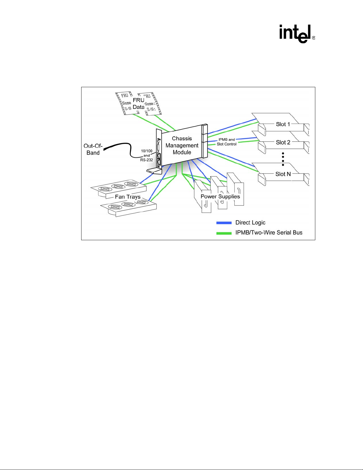
Figure 1. Functional Block Diagram
!
(73
8 9, 3
9: ,,3
*!*!+
(&! 01
!* "/+
"!
% 2
(&! 3
.%3 4)3+
. *)
$
%
&'
(" !)!
!*
!+
. .
,- ,!!
#
#
66
!
'"/
( !*
/ !+
2%
&
%
5%
/"%%
; / ! !* -!* - * ,, 6 :
14 Technical Product Specification
Page 15

Intel® NetStructureTMZT 7102 Chassis Manage ment Module
1.3 Terms Used in This Document
Table 1. Glossary
Acronym Description
CMM Chassis Management Module
CLI Command Line Interface
FRU Field Replaceable Unit
IPMI Intelligent Platform Management Interface
IPMB Intelligent Platform Management Bus
MIB Management Information Base
MIB II RFC1213 - A standard Management Information Base for Network Management
SEL System Event Log
SBC Single Board Computer
SNMP Simple Network Management Protocol
SNMP v.1 SNMP version 1
SNMP v.3 SNMP version 3
SDR Sensor Data Record
Introduction
Technical Product Specification 15
Page 16

Intel® NetStructureTMZT 7102 Chassis Management Module
Introduction
16 Technical Product Specification
Page 17

Intel® NetStructureTMZT 7102 Chassis Manage ment Module
Hardware Specifications
2.0 Hardware Specifications
2.1 Overview
The chassis management module (CMM) is intended to operate as a chassis management building
block in a CompactPCI chassis. The CMM uses a unique backplane interface pinout and requires a
dedicated slot within the chassis.
Caution: The ZT 7102 plugs into a dedicated chass is management slot. Syst em components w ill be damaged
if a standard 3U board is plugged into the chassis management slot.
Intelligent Platform Management Buses (IPMBs) are the primary management connection between
components. A unique star topology radiating from the CMMs is used to provide reliability,
flexibility and security. In some cases, direct logic is used to support non-intelligent devices and to
eliminate active components on the backplane and chassis.
The CMM provides 30 master/slave two-wire serial bus (2WSB) interfaces. The 2WSBs are
electrically equivalent to I2C*. As such, all outputs are open drain, so they are driven low and
passively pulled high. The 2WSB interfaces support multi-master operation on the bus, however
they do not support being the target of a read transaction from another master device. The 2WSB
interfaces are used by the CMM as IPMBs or non-intelligent management busses. Refer to the
individual sections for specific usage information. The 2WSB interfaces are used for:
• Up to 21 general-purpose slots (21 independent 2WSBs, 2WSB_S0 - 2SB_S20)
• Power supplies (two buses, 2WSB_PS0 and 2WSB_PS1 )
• Fan trays (one bus, 2WSB_FT)
• Chassis sensors (one bus, 2WS B_ CS )
• Chassis FRU mo dules (two indep endent buses, 2WSB_CF0 and 2WSB_CF1)
• Redundant CMM link (one bus for bi-directional communication, 2WSB_RCMM)
Technical Product Specification 17
Page 18
Intel® NetStructureTMZT 7102 Chassis Management Module
Hardware Specifications
2.2 System Architecture
Figure 2. System Management Architecture
2.3 Backplane Connections
2.3.1 Slot Connections
The slots are connected to the CMM via an IPMB defined in the PICMG* 2.9 specification. The
CMM also has connections for BD_SEL# and HEAL THY# signals to each slot. Each slot has an
independent IPMB, BD_SEL#, and HEALTHY#. The CMM supports up to 21 general-purpose
node slots.
The IPMB is used for IP MI management communication between the CMM and the board in the
slot. Each board that is to be managed by the CMM is required to support the IPMB as a
management channel.
BD_SEL# is used in CompactPCI slots to control board power and to detect board presence. The
CMM provides a bi-directional open drain driver for each BD_SEL#. The board installed in the
slot provides a pull-up resistor (1.2 KΩ ± 5% per PICMG* 2.0). The CMM provides a weak
pulldown resistor (and a diode clamp ). When not asserted , BD_SEL# can be read to determine if a
board is present in the slot. If BD_SEL# is high, a board is present. If BD_SEL# is not asserted a
board is not present. Asserting BD_SEL# allows the board to power up.
HEALTHY# is an input to the CMM. The CMM provides a pull-up resistor. The board in the slot
asserts HEALTHY# based on board power being good and optionally other board-specific
requirements. BD_SEL# must be asserted for HEALTHY# to be asserted. When BD_SEL# is
asserted, and a board is removed, HEALTHY# will be deasserted.
18 Technical Product Specification
Page 19

Intel® NetStructureTMZT 7102 Chassis Manage ment Module
2.3.2 Chassis Sensor Connections
Chassis sensors are connected to the CMM via one two-wire serial bus.
2.3.3 Chassis FRU Device Connections
Chassis sensors are connected to the CMM via one two-wire serial bus. The CMM provides two
2WSB interfaces for chassis FRU modules. Each chassis FRU module is on a dedicated 2WSB in
order to provide redundant access to vital chassis information (e.g., the physical location of the
chassis). The backplane FRU storage device used MUST be an Atmel* AT24C16 or other
24C16-compatible device.
2.3.4 Redundancy
The CMM supports redundant operation with automatic failover under hardware or software
control. The following hardware interfaces exist for the support of redundancy and automatic
failover:
• Cross-connected CMM present inputs (PRES_I#) and outputs (PRES_O#)
• Cross-connected CMM healthy inputs (HLY_I#) and outputs (HLY_O#)
• Cross-connected negotiation inputs (NEG_I) and outputs (NEG_O)
Hardware Specifications
The active CMM monitors its PRES_I# and HL Y_I# inputs to determine if it has a healthy, standby
CMM. The active CMM deasserts its HLY_O# output to trigger a failover to the standby CMM.
The cross-connected negotiation signals are used to assure that only one CMM is active at a time.
At anytime, the standby CMM can trigger a failover by driving its NEG_O output low.
2.4 Power Modules
Power supply sleds are connected to the CMM via two IPMBs. Each power supply sled connects to
one IPMB. Multiple power supplies can share a single IPMB. The CMM also provides independent
DEG#, FAIL#, and INH# signals as defined in PICMG* 2.11 for up to eight power supplies. The
CMM will communicate with intelligent supplies via the IPMBs. Non-intelligent supplies are
supported via the DEG# (degrade), FAIL# (fail), and INH# (inhibit) signals.
The CMM uses INH# rather than EN# t o control the power supplies. The EN# pin is grounded on
the backplane to signal to a power supply when it is fully seated in its connector.
2.5 Fan Modules
Fan trays are connected to the CMM via one two-wire serial bus (2WSB). Intelligent fan trays
communicate with the CMM via the IPMB. To support non-intelligent fan trays, the CMM also
provides independent fan tachometer input s for up to 16 fans, fan t ray pr esen t inputs for up to four
fan trays, and four fan speed outputs (four buffered copies of a single PWM). Non-intelligent fan
trays are monitored and controlled via the fan tachometer inputs and the fan speed output.
Technical Product Specification 19
Page 20
Intel® NetStructureTMZT 7102 Chassis Management Module
Hardware Specifications
2.6 Face Plate
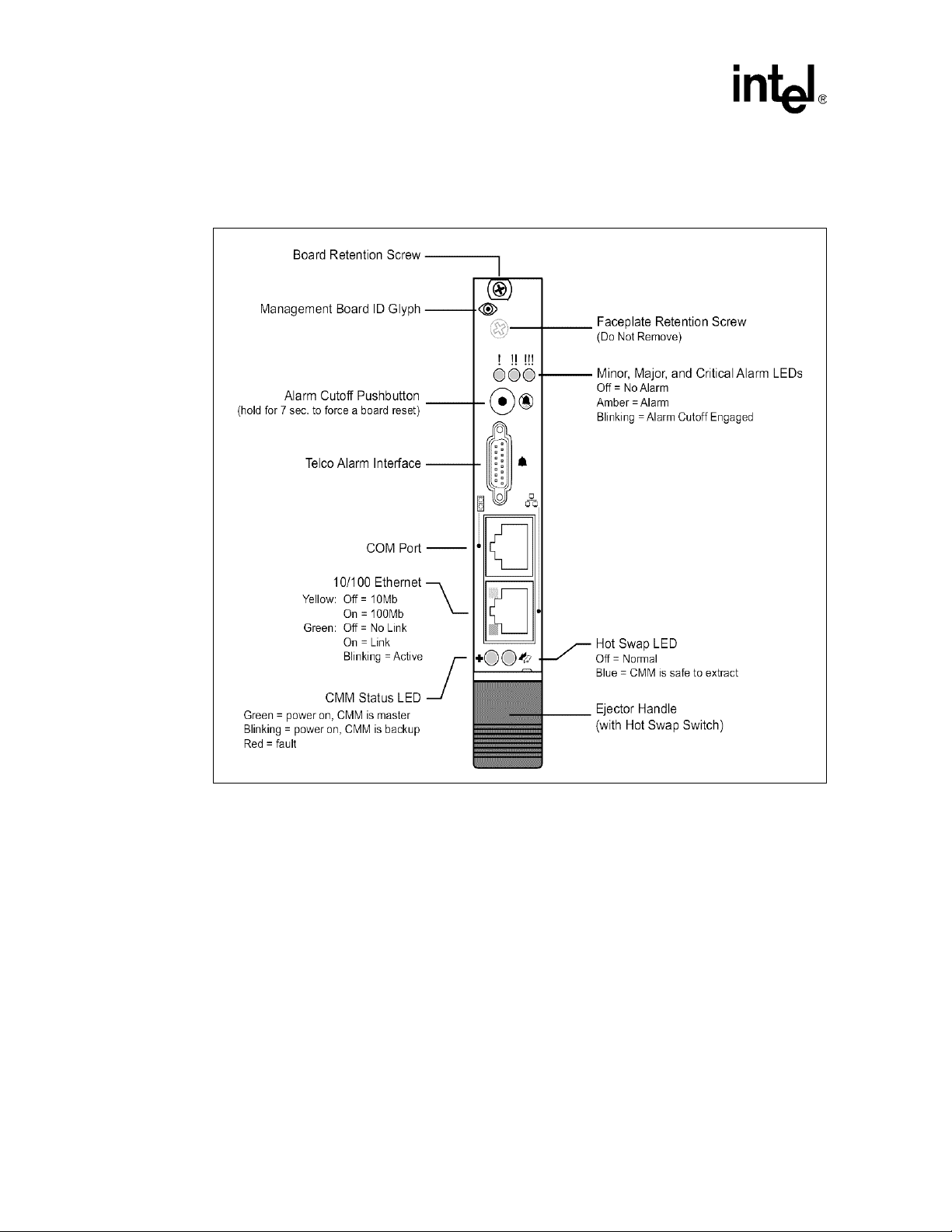
Figure 3. Face Plate
20 Technical Product Specification
Page 21

2.6.1 Faceplate Features
The following features are found on the faceplate of the ZT 7102:
T able 2. Faceplate Features
Feature Purpose
Minor, Major, and Critical Alarm
LEDs
Alarm Cutoff (ACO) push button
Telco Alarm I nterface (µDB15
connector)
COM Port (RJ-45 connector)
Ethernet Port (RJ-45 with LEDs)
CMM Status LED
Hot Swap LED
Ejector with hot swap switch
Intel® NetStructureTMZT 7102 Chassis Manage ment Module
Hardware Specifications
These LEDs indicate the presence of various event-triggered alarms.
The LEDs function as follows:
Off = no alarm triggered.
Amber = alarm triggered.
Blinking = alarm cutoff (ACO) is activated.
This push button toggles the ACO state. When ACO is activated, the
active alarm LEDs blink and all of the alarm relays are deactivated. This
button does not clear alarms.
The ZT 7102 can be reset by pressing and holding the ACO button for
about five seconds.
This interface relays alarm signals to off-board equipment. Contact Intel
for a compatible cable (µDB15 to standard DB15). See Appendix G,
“Customer Support.” for details.
This serial port may be used to access the CMM's Command Line
Interface (CLI).
This port provides an out-of-band 10/100 Ethernet connection. The
port's integrated LEDs function as follows:
Yellow: Off = 10 Mbit
On = 100 Mbit
Green: Off = No Link
On = Link
Blinking = Ac tivity
This LED indicates CMM status as follows:
Green = power is on and the board is acting as the master (active)
CMM.
Blinking green = power is on and the board is acting as the backup
(standby) CMM.
Red = the CMM needs attention (a critical problem exists).
This LED indicates when it is safe to remove the CMM from a live
(powered-on) chassis. The LED functions as follows:
Off = the CMM is not ready to be removed from a live chassis.
Blue = the CMM is ready to be removed from a live chassis.
The ejector functions as a handle and a lever for installing or removing
the CMM. The ejector incorporates a switch that tells the CMM when the
board is about to be removed from a system.
Technical Product Specification 21
Page 22
Intel® NetStructureTMZT 7102 Chassis Management Module
Hardware Specifications
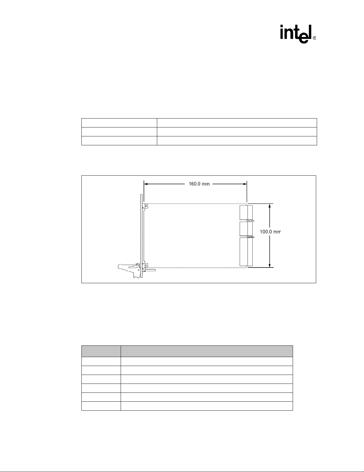
2.7 Mechanical
2.7.1 Board Dimensions and Weight
In a compatible enclosure, the ZT 7102 occupies a single 3U CMM slot. Mechanical dimensions
are shown in Figure 4 and outlined in Table 3.
Table 3. Board Dimensions and Weight
PCB Dimensions: 100 mm x 160 mm x 1.6 mm
Board Dimensions: 3U x 4HP (one slot)
Weight: 7.7 ounces w/ 128 Mbyte SODIMM
2.7.2 PCB Dimensions
Figure 4. PCB Dimensions
2.8 Connectors
As shown in Figure 5, the ZT 7102 includes several connectors to interface to application-specific
devices. A brief description of each connector is given in Table 4 below. A detailed descr iption and
pinout for the backplane connectors is given in the following sections.
Table 4. Connector Assignments
Connector Function
J1, Table 5 Backplane Connector (110-pin, 2mm x 2 mm, female)
J2, Table 6 Backplane Connector (55-pin, 2 mm x 2 mm, female)
J3, Table 7 Backplane Connector (55-pin, 2 mm x 2 mm, female)
J4 Connector reserved for test.
JA1, Table 10 Ethernet Connector (RJ-45, 8-pin)
J6, Table 11 Serial Port (RJ-45, 8-pin)
22 Technical Product Specification
Page 23

Table 4. Connector Assignments
Connector Function
J7, Table 12 Telco Alarm Connector (uDB-15, 15-pin)
J8, SODIMM Socket (144-pin)
J9 Connector reserved for test.
Figure 5. Connector Locations
Intel® NetStructureTMZT 7102 Chassis Manage ment Module
Hardware Specifications
Figure 6. Backplane Connectors - Pin Locations
Technical Product Specification 23
Page 24

Intel® NetStructureTMZT 7102 Chassis Management Module
Hardware Specifications
2.8.1 J1 Backplane Connector
J1 is a 110-contact, 2 mm x 2 mm female CompactPCI form-factor connector (AMP 352152-1).
See Table 5 for pin definitions and Figure 6, “Backplane Connectors - Pin Locations” on page 23
for relative pin placement.
Table 5. J1 Connector Pinout
Pin# A B C D E F
22 PDEG0# PDEG2# GND PDEG4# PDEG6#
21 PDEG1# PDEG3# IPMB_PWR PDEG5# PDEG7#
20 PFAIL0# PFAIL2# GN D PFAIL4# PFAIL6#
19 PFAIL1# P FAIL3# IPMB_PWR PFAIL5# PFAIL7#
18 PINH0# PINH2# GND PINH4# PINH6#
17 PINH1# PINH3# IPMB_PWR PINH5# PINH7#
16 PS_SCL0 PS_SDA0 GND PRES_I# GA0
15 PS_SCL1 PS_SDA1 RES FANP0# FANP2#
14 FT_SCL FT_SDA GND FANP1# FANP3#
13 CS_SCL CS_SDA RES FANPWM0 FANPWM2
12 CF_SCL0 CF_SDA0 GND FANPWM1 FANPWM3
11 CF_SCL1 CF_SDA1 RES FANTK0 FANTK8
10 RES RES GND FANTK1 FANTK9
9 RES RES RES FANTK2 FANTK10
8 STx SRx SRI FANTK3 FANTK11
7 SCTS SRTS SCD FANTK4 FANTK12
6 SDSR SDTR RES FANTK5 FANTK13
5 RPMAC # RPMIC# RES FANTK6 FANTK14
4 RPCR# RPMAR# RPMIR# FANTK7 FANTK15
3 BP_5V BP_N12V BP_12V BP_3.3V VIO
2 SwTx+ SwTx- GND RpTx+ RpTx1 SwRx+ SwRx- GND RpRx+ RpRx-
NOTE: # Designates a low true signal. All signals interface to medium length pins on the backplane.
GROUND
SHIELD
2.8.2 J2 Backplane Connector
J2 is a 55- contact, 2 mm x 2 mm female CompactPCI* form-factor connector (AMP* 352115-1).
See Table 6 for pin definitions and Figure 6 for relative pin placement.
24 Technical Product Specification
Page 25

Table 6. J2 Connector Pinout
Pin# A B C D E F
11 N_SCL1 N_SDA1 N_SCL10 N_SDA10 N_SCL18
10 N_SCL2 N_SDA2 N_SCL11 N_SDA11 N_SDA18
9 N_SCL3 N_SDA3 N_SCL12 N_SDA12 N_SCL19
8 N_SCL4 N_SDA4 N_SCL13 N_SDA13 N_SDA19
7 N_SCL5 N_SDA5 N_SCL14 N_SDA14 N_SCL20
6 N_SCL6 N_SDA6 N_SCL15 N_SDA15 N_SDA20
5 N_SCL7 N_SDA7 N_SCL16 N_SDA16 N_SCL21
4 N_SCL8 N_SDA8 N_SCL17 N_SDA17 N_SDA21
3 N_SCL9 N_SDA9
2 R_SCL IPMB_PWR RES
1
NOTE: # Designates a low true signal.
GND R_SDA CMM_SEL# NEG_I GND
All signals interface to medium length pins on the backplane except as noted.
= Interfaces to long connector pins on the backplane.
= Interfaces to short connector pins on the backplane.
Intel® NetStructureTMZT 7102 Chassis Manage ment Module
Hardware Specifications
GROUND
SHIELD
GND NEG_O HLY_O#
IPMB_PWR HLY_I#
2.8.3 J3 Backplane Connector
J3 is a 55-contact 2 mm x 2 mm female CompactPCI form-factor connecto r (AMP 352115-1). See
Table 7 for pin definitions and Figure 6 for relative pin placement.
Table 7. J3 Connector Pinout
Pin# A B C D E F
11 N_HLY1# N_BDS1# N_HLY10# N_BDS 10# N_HLY18#
10 N_HLY2# N_BDS2# N_HLY11# N_BDS11# N_BDS18#
9 N_HLY3# N_BDS3# N_HLY12# N_BDS12# N_HLY19#
8 N_HLY4# N_BDS4# N_HLY13# N_BDS13# N_BDS19#
7 N_HLY5# N_BDS5# N_HLY14# N_BDS14# N_HLY20#
6 N_HLY6# N_BDS6# N_HLY15# N_BDS15# N_BDS20#
5 N_HLY7# N_BDS7# N_HLY16# N_BDS16# N_HLY21#
4 N_HLY8# N_BDS8# N_HLY17# N_BDS17# N_BDS21#
3 N_HLY9# N_BDS9#
2 RES GND RES
1
IPMB_PWR RES PRES_O# PIMP1# IPMB_PWR
NOTE: # Designates a low true signal.
All signals interface to medium length pins on the backplane except as noted.
= Interfaces to long connector pins on the backplane.
= Interfaces to short connector pins on the backplane.
GROUND
SHIELD
IPMB_PWR PIMP0# RES
GND RES
Technical Product Specification 25
Page 26

Intel® NetStructureTMZT 7102 Chassis Management Module
Hardware Specifications
2.8.4 Backplane Pin Descriptions
Table 8. Pin Type Definitions
Pin Type Definition
OD O pen Drain
I Input
I/O Input/Output
O Output
Table 9. Pin Descriptions (Sheet 1 of 2)
Name Count Type Description
N_SCL[1..21] 21 OD Node IPMI clock
N_SDA[1..21] 21 OD Node IMPI data
PS_SCL[0..1] 2 OD Power Supply Chassis IMPI clock
PS_SDA[0..1] 2 OD Power Supply Chassis IMPI data
FT_SCL 1 OD Fan Tray Chassis IMPI clock
FT_SDA 1 OD Fan Tray Chassis IMPI data
CS_SCL 1 OD Chassis Sensor IMPI clock
CS_SDA 1 OD Chassis Sensor IMPI data
CF_SCL[0..1] 2 OD Chassis FRU IMPI clock
CF_SDA[0..1] 2 OD Chassis FRU IMPI data
R_SCL 1 OD Redundant CMM serial clock
R_SDA 1 OD Redundant CMM serial data
N_HLY#[1..21] 21 I Node Healthy (0 = Node is healthy)
N_BDS#[1..21] 21
SwTx(+/-) 2 I/O 10/100 Ethernet To Switch
SwRx(+/-) 2 I/O 10/100 Ethernet From Switch
FANTK[0..15] 16 I Fan Tach Inputs
FANPWM[0..3] 4 O Fan Speed Control (3.3 V = ON)
FANP#[0..3] 4 I Fan tray present (3.3 V = fan tray is missing)
PDEG#[0..7] 8 I Power supply degrade
PFAIL#[0..7] 8 I Power supply fail
PINH#[0..7] 8 O Power supply inhibit
STx 1 O Ser ial transmit
SRx 1 I Serial receive
SCTS 1 I Serial clear to send
SRTS 1 O Serial request to send
SDSR 1 I Serial data set ready
OD
I/O
Node Board Select (5 V = Node is present, drive to 0
to turn node on)
26 Technical Product Specification
Page 27

Table 9. Pin Descriptions (Sheet 2 of 2)
Name Count Type Description
SDTR 1 O Serial data terminal ready
SRI 1 I Serial ring indicator
SCD 1 I Serial carrier detect
RpTx(+-) 2 I/O 10/100 Ethernet To rear panel
RpRx(+-) 2 I/O 10/100 Ethernet From rear panel
NEG_O 1 O Negotiate output to other CMM
NEG_I 1 I Negotiate input from other CMM
HLY_O# 1 O Healthy output to other CMM
HLY_I# 1 I Healthy input from other CMM
PRES_I# 1 I Other CMM is present (0V)
PRES_O# 1 O Grounded on CMM.
GA0 1 I Location Address
CMM_SEL# 1 I
GND 14 I CMM GND
IPMB_PWR 8 I CM M Power
BP_12V, BP_N12V,
BP_5V, and
BP_3.3V
RPMAC# 1 I Rear panel major alarm clear
RPMIC# 1 I Rear panel minor alarm clear
RPCR# 1 O Rear panel critical alarm relay
RPMAR# 1 O Rear panel major alarm relay
RPMIR# 1 O Rear panel minor alarm relay
VIO 1 I
RES 18 NC No Connect on Backplane
TOTAL 220
4 I Monitor backplane power 12,-12,5,3.3
Intel® NetStructureTMZT 7102 Chassis Manage ment Module
Hardware Specifications
Tells CMM it has been seated. (Backplane grounds
this pin)
Backplane IO voltage (may not be present in non-PCI
system)
2.8.5 JA1 Ethernet Port
JA1 is an RJ -45 Etherne t port providing 10 Mbit (10BASE -T) and 100 Mbit (100BASE-TX)
protocols. JA1 connects to the CMM's LAN 0 Ethernet channel. A second Ethern et channel, LAN1,
is only available at the backplane.
Two LEDs are located in the RJ-45 Ethernet connector:
• Yellow indicates speed
• Green indicates a link/activity
See Table 10 for JA1 Ethernet port pin definitions.
Technical Product Specification 27
Page 28

Intel® NetStructureTMZT 7102 Chassis Management Module
Hardware Specifications
Table 10. JA1 Ethernet Port Pinout
Pin # Description
1TX+
2TX3RX+
4,5 Unused pair; terminated on ZT 7102
6RX7 Unused pair; terminated on ZT 7102
2.8.6 J6 Serial Port
J6 is an RJ-45 connector providing a front-panel RS-232 serial port interface. Serial port signals are
also directed out connector J1 to the backplane. See Table 11 f or J6 serial port pin definitions.
Table 11. J6 Serial Port Pinout
Pin# Function Description
1 SRTS Serial Request To Send
2 SDTR Serial Data Terminal Ready
3 STx Serial Transmit
4 GND Ground
5 GND Ground
6 SRx Serial Receive
7 SDSR Serial Data Set Ready
8 SCTS Serial Clear to Send
- SRI Serial Ring Indicator (not utilized)
- SCD Serial Carrier Detect (not utilized)
2.8.7 J7 Telco Alarm Connector
J7 is a µ DB-15 connector providing a front-panel telco alarm interface. See Table 12 for J7 Telco
alarm connector pin definitions. Contact Intel for information about obtaining a compatible
µDB-15 to DB-15 cable. Contact information is located in Appendix G, “Customer Support”.
For additional information on the Telco Alarm Connector, refer to the Wiring Telco Alarm
Connectors Application Note posted at the following location:
http://www.intel.com/design/network/applnots/273926.htm
28 Technical Product Specification
Page 29

Intel® NetStructureTMZT 7102 Chassis Manage ment Module
Table 12. J7 Telco Alarm Connector Pinout
Pin # Function Description
1 AMIR+ MinorReset +
2 AMIR- MinorReset 3 AMAR+ MajorReset +
4 AMAR- MajorReset 5 ACNO CriticalAlarm - NO
6 ACNC CriticalAlarm - NC
7 ACCOM CriticalA larm - COM
8 AMINO MinorAlarm - NO
9 AMINC MinorAlarm - NC
10 AMINCOM MinorAlarm - COM
11 AMANO MajorAlarm - NO
12 AMANC MajorAlarm - NC
13 AMACOM MajorAlarm - COM
14 APRCO PwrAlarm - NO
15 APRCOM PwrAlarm - COM
- GND Not Utilized
COM=Common
NO=Normally Open
NC=Normally Closed
Hardware Specifications
2.9 Electrical and Environment al
The ZT 7102 requires +5 VDC ±5% @ 1.8 A typical. CMM power comes from the backplane's
IPMI_PWR rail; other voltages are derived as needed.
Caution: The processor core temperature must never exceed 100° C under any condition of ambient
temperature or usage. This may result in permanent damage to the processor.
2.9.1 CMM Power
CMM power comes from the backplane’s 5 V power (IPMI_PWR). See Table 13 for available
voltages.
Table 13. CMM Power Availability
Voltage Maximum Current Where Used
5 100 mA Miscellaneous components that cannot use 3.3 V.
3.3 4 A 80312 and most logic
2.5 700 mA FPGA core
1.5 500 mA 80200 core
Technical Product Specification 29
Page 30

Intel® NetStructureTMZT 7102 Chassis Management Module
Hardware Specifications
2.9.2 Power Ramp Circuitry
The ZT 7102 features a power controller with power ramp circuitry to allow the board’s voltages to
be ramped in a controlled fashion. The power ramp cir cuitry eliminates large voltage or current
spikes caused by hot swapping boards. Controlled voltage ramping is a requirement of the
CompactP CI* Hot Swap Specification, PICMG* 2.1, Version 2.0.
Fault current sensing is also provided. When a board fault (short circuit) or overcurrent condition is
detected, the hot swap controller automatically removes power from the CMM component s, and
the Status LED on the faceplate illuminates red (see Table 3, “Face Plate” on page 20). Fault
protection activates when the current exceeds 10 A for longer than 10 ms.
2.9.3 Operating Temperature
The ZT 7102 processor can operate between +5° C and approximately +65° C ambient. It is the
users' responsibility to ensure that the ZT 7102 is installed in a chassis capable of supplying
adequate airflow. The maximum power dissipation of the processor is 15 W (10 W typical).
External airflow must be provided at all times.
Caution: The processor core temperature must never exceed 100° C under any condition of ambient
temperature or usage. This may result in permanent damage to the processor.
2.9.4 Reliability
MTBF: 479,000 hours at 40° Celsius
MTTR: Three minutes (based on hot-swap board replacement), plus system startup
2.9.5 Absolute Maximum Ratings
See Table 14 for absolute maximum ratings.
Note: These are stress ratings only. Do not operate the ZT 7102 at these maximums. See Section 2.9.6,
“DC Operating Characteristics” on page 31 for operating conditions.
Table 14. Absolute Maximum Ratings
Signal or Characteristic Range
Supply Voltage, V
Storage Temperature -40° to +85° Celsius
Operating Temperature +5° to +65° Celsius
Non-Condensing Relative Humidity <95% at 40° Celsius
CC
5 V ±5% with 50 mV maximum ripple
30 Technical Product Specification
Page 31

Intel® NetStructureTMZT 7102 Chassis Manage ment Module
2.9.6 DC Operating Characteristics
T a ble 15. DC Operating Characteristics
Signal Range
Hardware Specifications
Supply Voltage, V
Supply Current, I
CC
CC
2.10 Onboard Switches
The ZT 7102 contains a push-button switch on the faceplate and one bank of DIP switches on the
component side of the board. See Table 16 for switch identification and functions. Factory defa ult
switch settings are shown in Figure 7.
Note: Where switches are referenced in this chapter, “SWx” refers to the switch number and “-N” refers
to the switch segment (SW1-2 indicates “switch number 1, segment 2”).
Table 16. Switch Cross Reference Table
Switch Function
S1, “S1 (Alarm Cutoff and Board Reset)” on page32 Alarm Cutoff and Board Reset
SW1-1, “SW1-1 (Password Reset)” on page 32 Reset Password
SW1-2 Reserved
SW1-3 Reserved
SW1-4 Reserved
4.85 V minimum to 5.25 V maximum
1.8 A average (with 733 MHz processor and 32 Mbyte of SDRAM. Peak
(short duration) power supply current may be significantly higher (up to
50%) and varies depending upon the application.
See Figure 7 for the default switch configuration.
Figure 7. Default Switch Configuration
Technical Product Specification 31
Page 32

Intel® NetStructureTMZT 7102 Chassis Management Module
Hardware Specifications
2.10.1 Switch Descriptions
The following topics provide a detailed description of each switch.
2.10.1.1 S1 (Alarm Cutoff and Board Reset)
S1 is a push button at the faceplate of the ZT 7102. S1 toggles the CMM's alarm cutoff (ACO)
state. When ACO is activated, the active alarm LEDs blink and the alarm relays are deactivated.
This button does not clear alarms.
The Alarm Cutoff feature automatically cancels itself under the following conditions:
• When the ACO is engaged for more than 10 minutes without an active alarm present. This
prevents the ACO from being accidentally left engaged after an alarm is cleared).
• When the ACO is engaged for more than x minutes, ev en if an active alarm is present ( x can be
set in the Command Line Interface with the Data item keyword AlarmTimeOut, see Table 23,
“dataitem (-d) Keywords for All Locations” on page 58).
In addition to its ACO function, S1 is used to reset the CMM by pressing and holding the button for
about five seconds. Reset is discussed in more detail in Section 4.0, “CMM Redundancy,
Synchronization and Failover” on page 39.
2.10.1.2 SW1-1 (Password Reset)
Closing this switch resets the CMM's root logon password. Use this feature if you forget your
password or want to restore the default root password for other reasons. For more information
about resetting to the default root password, refer to Section 9.0, “Resettin g the Password” on
page 63.
Table 17. SW1-1 Functions
SW1-1 Function
Open [default] Does not reset the CMM's root password at reboot.
Closed Resets the CMM's root password at reboot.
2.11 Processor and Chipset
The Intel® IOP310 chipset contains two devices, the Intel® 80200 processor and the Intel® 80312
I/O companion chip. The 733 MHz 80200 processor features 32 Kbit data and instruction caches.
The 80312 companion chip provides a memory controller and a PCI interface for the CMM's
Ethernet controllers. Appendix E, “Datasheet Reference” contains a link to the datasheet for the
chipset.
The ZT 7102 uses the Intel
microarchitecture, this chipset combines high performance processing with ultra-low power
consumption.
®
IOP310 I/O proc e ssor chipset. Based on Intel XScale®
32 Technical Product Specification
Page 33

2.12 Memory
The ZT 7102 includes 128 Mbytes of SDRAM on a Small Outline Dual Inline Memor y Module
(SODIMM). The SODIMM used is 16 Mbits x 72 PC133 unbuffered SDRAM with ECC on a
144-pin module.
2.12.1 Removing the SODI MM
The following instructions cover the mechanical aspects of removing the SODIMM from a
ZT 7102.
1. T ake the necess ary precaution s to protect the ZT 7102 and the SODIMM from static discharge.
2. Locate the SODIMM socket. Refer to Table 4, “Connector Assignments” on page 22 for the
socket's location.
3. Press outward on the clips at either end of the SODIMM socket (press both clips at the same
time) until the module ejects from the slot and tilts upward.
4. Pull the SODIMM away from the socket.
2.12.2 Installing Memory
Intel® NetStructureTMZT 7102 Chassis Manage ment Module
Hardware Specifications
The following instructions cover the mechanical aspects of installing the SODIMM in a ZT 7102.
1. T ake the neces sary precautions to protect the Z T 7102 an d the SODIMM from s tatic discharge.
2. Hold the SODIMM at an angle and push it into the SODIMM socket. Refer to Table 4,
“Connector Assignments” on page 22 for the socket's location.
3. Align the notches on the ends of the module with the matching bumps on the latches and
gently push the module down until it clicks in place.
2.13 Flash
The ZT 7102 uses an on-board 64 Mbyte flash memory device.
2.14 Dual Ethernet Controllers
The ZT 7102 uses two Intel®82559 Fast Ethernet Controllers. The 82559 consists of both the
Media Access Controller (MAC) and the physical layer (PHY) interface combined into a single
component solution.
The CMM provides an RJ-45 connector on the faceplate to connect to out-of-band 10/100 LAN0.
This connector is labeled with the Ethernet icon (refer to “Face Plate” on page 20). Care should be
taken not to confuse the RJ-45 Ethernet port with the RJ-45 serial port that is next to it. (Note that
the Ethern et port has integrated speed and activity LEDs).
2.15 Serial I/O
The ZT 7102 provides an RS-232 compatible RJ-45 serial port connector on the faceplate. Serial
port signals are also available for rear panel access.
Technical Product Specification 33
Page 34

Intel® NetStructureTMZT 7102 Chassis Management Module
Hardware Specifications
2.16 Telco Alarm Signal
2.16.1 Alarm Relays
The ZT 7102’s alarm relay circuits are capable of carrying 60 VDC or 1 A, wit h a maximum ra ting
of 30 VAC.
2.16.2 Opto Inputs
The ZT 7102 accepts timed pulse inputs for clearing Minor and Major alarm states (there is no
reset for the Critical state). Reset is accomplished by asserting a voltage differential from 3.3 V to
48 V for between 200 and 300 ms. The acceptable voltage range is from 0 to 48 VDC continuous
(handles up to 60 VDC at a 50 percent duty cycle). The current drawn by a reset input should not
exceed 12 mA.
Caution: Do not apply more than 60 V (maximum) to any pin or combination of pins on the CMM's J7 Telco
Alarm connector.
2.17 Real Time Clock
A Dallas Semiconductor* DS1307 Serial Real-Time Clock allows the ZT 7102 to keep track of
time for accurate event logging. The DS1307 features 56 bytes of nonvolatile SRAM, a 100-year
calendar, and battery backup.
The Real-Time Clock keeps time in UTC only. If the time is set for a different time zone, as in the
example below, the difference will be automatically calculated giving the UTC equivalent. In this
example, the time will be set 8 hours ahead of the local time.
To set the real-time clock, enter the correct date and time in the following format:
setdate 'Thu Apr 01 09:04:29 PST 2004'
The above command would set the time and date to the following:
Thu Apr 1 17:04:29 UTC 2004
Note: The real-time clock should be set to current date and time out of the box.
2.18 Networ k Time Synchronization
The CMM supports the RFC 868 Time Protocol. This allows the CMM to be configured to retrieve
the date and time from a server over a TCP/IP network using the rd ate command. To properly
configure time synchronization using the RFC 868 Time Protocol, follow the steps below.
Enable RFC 868 Time Protocol on a Linux/Unix Host (server):
• In general this depends upon the OS and version. Please consult your OS documentation.
• The easiest way to enable this service is to use the OS GUI to enable the "time" server. This is
part of inetd/xinetd.
34 Technical Product Specification
Page 35

Enable RFC 868 Time Protocol on CMM (client):
1. Create file "/etc/rdate.cfg".
2. Edit file "/etc/rdate.cfg" with a valid host name or IP address of an enabled RFC 868 Time
Protocol server.
3. Reboot the CMM, and check the new date (use "date") to make sure it is identical to the RFC
868 Time Protocol server (use "busybox rdate -p <host name or IP>".
4. This file will only be preserved during upgrades to same or newer versions.
Note: Since rdate is executed during CMM boot, it is possible that on a chassis powerup the CMM may
not be able to sync up with a server if the network path to it is through the backplane Ethernet port.
For proper network time synchronization during CMM boot, the CMM should be able to contact
the time server through the front Ethernet port.
2.19 Watchdog Timer
The ZT 7102 uses a Maxim* MAX6374KA-T watchdog timer to supervise processor activity.
When the software fails to strobe the watchdog within a set period (once every second), the
watchdog alerts the CMM's Complex Programmable Logic Device (CPLD), which resets the CPU.
Intel® NetStructureTMZT 7102 Chassis Manage ment Module
Hardware Specifications
2.20 Battery Backup
The CMM contains a CR 1025 onboard battery to retain certain functions such as the real time
clock, even when no standb y power to the board is present. I f it becomes apparent that the time and
date no longer stay current, then the battery should be replaced. The battery should only be
replaced with a lithium CR 1025 or equivalent. After the battery is replaced, use the setdate
command to set the time correctly. See Section 2.17, “Real Time Clock” on page 34 for
information on setting the time and date.
Note: Date and time are critical to the operation of the CMM because health events are stamped with this
information. Always ensure the date and time of the CMM are kept current.
2.20.1 Replacing the Battery
1. Slide the battery out from the battery retention clip.
2. Slide the new battery into the clip with the positive (+) side up. The metal arm of the retention
clip should rest on top of the positive side of the battery.
T a ble 18. Battery Characteristics
Characteristic Description
Battery Voltage: 3 V
Battery Capacity: 30 mAh
Real-Time Clock Requirements: 300 uA typical, 500 uA maximum (Vbat = 3 V, Vcc = 0 V)
Real-Time Clock Data Retention:
Electrochemical Construction: Long-life lithium with solid-state polycarbon monofluoride cathode.
11.4 years typical/6.8 years minimum (not powered). When powered,
RTC takes its power from +5v, not battery.
Technical Product Specification 35
Page 36

Intel® NetStructureTMZT 7102 Chassis Management Module
Hardware Specifications
Caution: The ZT 7102 contains a lithium battery. Do not disassemble or recharge th e battery. Do not dispose
of the battery in fire. When the battery is replaced, the same type or an equivalent type
recommended by the manufacturer must be used. Used batteries must be disposed of according to
the manufacturer's instructions.
2.21 Running Your System Without A CMM
In CMM-based systems, the CMM controls power to the general-purpose slots in accordance with
the PICMG* 2.1 specification. PICMG* 2.1 defines the power control signals (BD_SEL#) as
pulled up on general-purpose boards. When the BD_SEL# signals are not asserted (grounded) by
external means, the general-purpose boards will not power up . Therefo re, to operate a CMM-b ased
system without a CMM board, BD_SEL# must be grounded at each slot on the backplane.
Your system may have jumpers at each slot on the backplane to ground BD_SEL#. Inserting the
BD_SEL# jumper will allo w the n ode slot to po wer up regardl ess of the CMM. Node slots with t he
BD_SEL# jumper installed canno t be managed using the CMM. Refer to system-specific
documentation for more information about running the system with or without a CMM board.
36 Technical Product Specification
Page 37

Intel® NetStructureTMZT 7102 Chassis Manage ment Module
3.0 Software Specifications
3.1 Operating System
Software Specification s
The CMM runs a customized version of embedded BlueCat* Linux* 4.0 on an Intel® 80200
processor with Intel XScale
the web at http://www.lynuxworks.com
®
technology. Development support for BlueCat Linux* is avail able on
.
3.2 Command Line Interface (CLI)
The Command Line Interface (CLI) connects to and communicates with the intelligent
management devices of the chassis, boards and the CMM itself. The CLI is an IPMI-based library
of commands that can be accessed directly or through a higher-level management application.
Administrators can access the CLI through Telnet or the CMM's serial port. Using the CLI, users
can access information about the current state of the system including current sensor values,
threshold settings, recent events, and overall chassis health.
3.3 SNMP/UDP
The chassis management modul e supports both queries and traps on SNMP v1 or v3. The SNMP
version can be configured through the CLI interface. The default is for SNMP v1. A MIB for the
entire platform is included with the CMM.
Along with SNMP traps, the CMM sends UDP alerts to port 10000. The content of these UDP
alerts is the same as the SNMP traps.
3.4 Remote Procedure Call (RPC) Interface
In addition to the console command-line interface, the CMM can be administered by custom
remote applications via remote procedure calls (RPC).
3.5 Ethernet Interfaces
Eth1 is the Ethernet port going to the backplane on the CMM. Eth1 should remain static at all
times. It is through this port that synchronization will be attempted initially. For synchronization to
occur on eth1, both Ethernet switches must be pres ent in the chassis.
Eth1:1 is a an IP address used to connect to the active CMM at any time through the chassis
backplane and therefore should remain static. Eth1:1 is a static alias of eth1 defined in the
/etc/ifcfg-eth1 file as STATICIP2. Because this IP address is synced between the two CMMs, it
should only be changed on the active CMM. See Section 7.3.1, “Setting IP Address Properties” on
page 54 on how to set the eth1:1 IP address.
Eth0 is the Ethernet interface on the front of the CMM that can connect to an external or private
management network through a s witch or t hrough a cro ssov er to the ot her CMM. Thi s is used i f no
Ethernet switches are available in the chassis. Eth0 can be set to static or DHCP.
Technical Product Specification 37
Page 38

Intel® NetStructureTMZT 7102 Chassis Management Module
Software Specifications
In a platform containing redundant CMMs, upon initial power up, both CMMs will have identical
IP addresses on all of their Ethernet interfaces. The s tandby CMM will automatically decr ement its
IP address on Eth1 by 1 so t hat s yn chronization can occur; however, the user must change these IP
addresses upon initial login so that an address conflict does NOT occur and synchronization and
failover can operate correctly. See Section 7.3.1, “Setting IP Address Properties” on page 54 for
further information and instructions on changing the IP addresses. See Section 4.0, “CMM
Redundancy, Synchronization and Failover” on page 39 for further information regarding
synchronization, failover, and redundancy.
3.6 Sensor Event Logs (SEL)
The chassis management module utilizes a dual domain for hosting the sensor event logs (SEL) of
the chassis components and boards used in the platform. With the dual domain architecture, some
SEL files are stored locally on the CMM in /etc/cmm, and some SEL files are stored on the
individual blades.
For the CMM, backplane, and chassis components, the CMM stores the SELs locally on the CMM
in /etc/cmm.
3.6.1 CMM SEL Architecture
The SEL files stored locally on the CMM in /etc/cmm have a maximum size of 8 Kbytes. If a SEL
becomes full, the CMM will wrap the SEL to the beginning, and all previous SEL entries will be
cleared.
3.6.2 Satellite Management Controller (SMC) Boards
For a board inserted into the platform acting as a satellite management controller (SMC), the CMM
will also store the SEL file locally. Some SMC-based boards may also contain their own SEL.
Health events generated from SMC-based boards will be stored in the SEL on the CMM as well as
on the SMC board if a SEL exists. When the command is issued to get the SEL from an
SMC-based board, the CMM will always retrieve the SEL file stored locally on the CMM in
/etc/cmm.
3.6.3 Baseboard Management Controller (BMC) Boards
For boards inserted into the system acting as a baseboard management controller (BMC), the SEL
file will be stored on that particular board. All health events will be logged in the SEL on that
board. When the command is issued to get the SEL from the board, the CMM will retrieve the
entire SEL via IPMB from that board.
3.6.4 Retrieving a SEL
The CLI can be used to retrieve the SEL for a location. To retrieve the SEL for a particular
location, issue the following get command:
cmmget -l [location] -d SEL
Where location is the component you wish to retrieve the SEL for (cmm, chassis, bladeN).
38 Technical Product Specification
Page 39

Intel® NetStructureTMZT 7102 Chassis Manage ment Module
CMM Redundancy, Synchronization and Failover
4.0 CMM Redundancy, Synchronization and Failover
4.1 Overview
The CMM supports redundant operation with automatic failover in chassis using redundant CMM
slots. In systems where two CMMs are present, one acts as the active chassis manager and the other
as standby. Both CMMs monitor each other, and either can trigger a failover if necessary.
Data is always synchronized from the active CMM to the standby CMM whenever any changes
occur. Exis ting data o n the standby CMM is over written. A f ull synchronization b etween the active
and standby CMM occurs on initial power up or insertion of a new CMM. See Table 19, “CMM
Synchronization” on page 40 for a list of data items that are synchronized between the active and
standby CMM.
4.2 Hardware Redundancy Specification
The following hardware interfaces exist for the support of redundancy and automatic failover:
• Cross-connected CMM present inputs (PRES_I#) and outputs (PRES_O#)
• Cross-connected CMM health inputs (HLY_I#) and outputs (HLY_O#)
• Cross-connected negotiation inputs (NEG_I) and outputs (NEG_O)
The active CMM monitors its PRES_I# and HLY_I# inputs to determine if it has a healthy standby
CMM. The active CMM deasserts its HLY_O# output to trigger a failover to the standby CMM.
The cross-connected negotiation signals are used to assure that only one CMM is active at a time.
At any time, the standby CMM can trigger a failover by driving its NEG_O output low.
4.3 Synchronization
To ensure data on the standby CMM matches the data on the active CMM, the active CMM
synchronizes its data with the standby CMM, overwriting any existing data on the standby CMM.
The CMMs will initially fully synchronize data from the active to the standby CMM approximately
30 seconds after the CMMs boot (which can take up to 2 minutes total for both CMM boot and
synchronization). An insertion of a new CMM will also cause a full synchronization from the
active to the newly inserted standby, which also takes 2 minutes. Partial synchronization will also
occur any time files are modified or touched via the Linux* “touch” command. Date and time are
synched every hour.
Note: During synchronization, the LEDs on the standby CMM may blink on and off as the healthevents
that were logged in the SEL are synchronized.
The following items are synchronized between CMMs. During a full synchronization, all of these
files and data are synchronized. A change to any of these files results in that file being sy nche d.
The active CMM overwrites these files on the standby CMM.
Technical Product Specification 39
Page 40

Intel® NetStructureTMZT 7102 Chassis Management Module
CMM Redundancy, Synchronization and Failover
Table 19. CMM Synchronization
File(s) or data Description Path:
/etc/cmm.cfg CMM’s main configuration file Ethernet
/etc/passwd Password file Ethernet
/etc/shadow Password file Ethernet
/etc/cmm/sel_* All SEL files except the CMM SEL files Ethernet
/etc/cmm/*.bin All SDR Files Ethernet
/etc/cmm/*.sif All SIF Files Ethernet
/etc/cmm/DroneList.cfg Drone mode compatible forms Ethernet
/etc/cmm/PWMMap.cfg PWM Fanspeed Mapping Ethernet
/etc/cmm/SlotLayout.cfg Chassis slot layout configuration Ethernet
/etc/var/snmpd.conf SNMP configuration files Ethernet
/etc/snmpd.conf SNMP configuration files Ethernet
/home/scripts Entire user scripts area Ethernet
date and time Date and time IPMB
IP Address Settings CMM eth1, eth1:1, and eth0 IP address settings IPMB
Blade power states Status of blade power states IPMB
Power Supply Inhibit States Status of power supplies that are inhibited by the CMM IPMB
Warning: The /.rhosts file is used for synchronization and should NEVER be modified.
4.3.1 Synchronization Requirements
For synchronization to occur:
• The CMMs must be able to communicate with each other over their dedicated IPMB. The
CMMs use a heartbeat via their dedicated IPMB to determine if they can communicate with
each other over IPMB.
• An Ethernet connection must exist between the two CMMs. The CMMs must be able to ping
each other via Ethernet for synchr onization to b e succes sful. This can be a connection through
the Ethernet switches in the chassis, which requires both switches to be present in the chassis.
A connection can occur through an external Ethernet switch conn ected to the front ports of the
CMM pair, or alternatively, the connection can be a crossover cable connecting the two front
ports of the CMM pair. If synchronization fails on Eth1, it will be attempted on Eth0. If the
CMMs cannot successfully ping each other via Eth0 or Eth1, synchronization cannot occur.
A failure of synchronization to occur will result in a health event being logged in the chassis SEL,
however this will not inhibit a failover from occurring.
40 Technical Product Specification
Page 41

Intel® NetStructureTMZT 7102 Chassis Manage ment Module
4.4 CMM Failover
Once information is synchronized between the redundant CMMs, the active CMM will constantly
monitor its own health as well as the health of the standby CMM. In the event of one of the
scenarios listed in the sections that follow, the active CMM will automatically fail over to the
standby CMM so that no management functionality is lost at any time.
4.4.1 Scenarios That Force a Failover
The following scenarios cause a failover as long as the s tandby CMM is operational:
• The active CMM is pulled out of the chassis.
• The active CMM’s HEALTHY# signal is deasserted.
• A reboot command is issued to the active CMM.
• The front panel reset button on the active CMM is pushed in for more than five seconds.
• The internal synchronization code version of the active CMM is less than that of the standby
CMM.
4.4.2 Scenarios That Prevent Failover
CMM Redundancy, Synchronization and Failover
The following are reasons a failover cannot occur:
• The active CMM cannot communicate with the standby CMM via their IPMB bus.
• Not all data has been completely synchronized between the CMMs.
To determine the active CMM, use the CLI command:
cmmget –d redundancy
Eth1:1 will always point to the active CMM, which will allow you to access the active CMM
through the chassis at all times.
4.4.3 Scenarios That Failover to a Healthier Standby CMM
The scenarios listed below can only cause a failover if the standby CMM is in a healthier state than
the active CMM. The health of the CMM is determined by computing a CMM health score, which
is equal to the sum of the weights of the following active conditions. A CMM health score is
determined for each CMM whenever any of these conditions occur on the active CMM. The CMM
health score is composed of the sum of the weights of any of the three conditions listed below. Ea ch
condition has a default weight of 1 assigned to it, causing all conditions to have equal importance
in causing failover.
To determine if a failover is necessary when one of these conditions occurs, the active CMM
computes its CMM health score, and r eques t s the health score of the standby CMM. If the score of
the standby CMM is LESS than the score of the active CMM, a failover will occur. If a failover
does not occur, the Chassis SEL will contain an entry indicating the reason failover did not occur.
1. SNMPTrapAddress1 ping failure:
A condition is asserted and a health score is computed if the active CMM cannot ping its first
SNMP trap address as defined in the SNMPTrapAddress1 setting. Only a ping failure of the
first SNMP trap address (SNMPTrapAddress1) can cause the condition to assert.
SNMPtrapaddress2 through SNMPtrapaddress5 do not perform this ping test.
Technical Product Specification 41
Page 42

Intel® NetStructureTMZT 7102 Chassis Management Module
CMM Redundancy, Synchronization and Failover
Note: The frequency of the ping to the first trap address can vary from one second to approximately 20
seconds.
2. Unhealthy Ethernet Switch:
A condition is asserted and a health score is computed if the active CMM’s corresponding
Ethernet switch is not healthy or not present. The switch health is determined by the state of
the HEALTHY# hardware signal coming from the Ethernet switch. Refer to the chassis
specification to see which switch corresponds to the CMM. If both CMMs have unhealthy
switches or are not present in the chassis, then a failover can still occur based on other failover
conditions depending on the CMM health scores.
3. Critical events on the active CMM:
A condition occurs if the active CMM has critical events for any of the CMM sensors (not
chassis or blade sensors). Critical events are events associated with crossing an upper o r lower
nonrecoverable threshold of a sensor. If both CMMs have critical CMM events, then the
number of major and minor CMM events is examined to decide if a failover should occur. The
number of major events is compared, and if they are equ al, the number of minor e vents is used.
4.4.4 Scenarios That Failover to an Equally Healthy CMM
The following conditions will cause a failover only if the health score of the standby CMM is equal
to that of the active CMM:
1. The ejector latch on the active CMM is opened.
2. A manual failover is executed on the active CMM.
4.4.5 Failover Timing
Times required to detect different possible failover conditions and perform data synchronization
vary. For example, detecting network connection loss can take up to approximately 20 seconds.
Complete synchronization typically takes 7 to 30 seconds to occur, assuming both CMMs are fully
booted and a healthy Ethernet network connection and IPMB connection exist between the two
CMMs). Synchronization with a newly inse rted CMM can take two minutes, since a n ewly inserted
CMM needs that time to boot and initialize.
Once the CMM data is initially synchronized, failover happens instantaneously at the hardware
level. However, the CMM software requires some time to initialize various components following
a failover. Software-based remote management applications accessing the CMM will need to
reconnect to the newly active CMM. The newly active CMM may respond with unexpected errors
while initializing.
4.4.6 Manual Failover
The following command can be issued to the active CMM to cause a failover manually to the
standby CMM:
cmmset -l cmm -d failover -v 1
A manual failover can only be initiated on the active CMM. A failover will only occur if the
standby CMM is at least as healthy as the active CMM. Once the command executes, the former
standby CMM immediately becomes the active CMM.
If the failover could not occur, the CLI will indicate the reason why the failover could not occur,
and a SEL event will be recorded.
42 Technical Product Specification
Page 43

Intel® NetStructureTMZT 7102 Chassis Manage ment Module
CMM Installation and Removal
5.0 CMM Installation and Removal
This chapter describes the steps necessary to install and set up the ZT 7102 Chassis Management
Module (CMM). It includes instructions on unpacking, installing, and removing the CMM. Some
systems may come with the CMM(s) already installed.
Caution: The ZT 7102 plugs into a dedicated chassis management slot. System components will be damaged
if a standard 3U board is plugged into the chassis management slot.
5.1 Unpacking
Check the shipping carton for damage. If the shipping carton and contents are damaged, notify
Intel Customer Support. Retain the shipping carton and packing material for inspection by the
carrier. Obtain authorization before returning any product to Intel. Refer to Appendix G, “ Customer
Support” for assistance information.
Caution: This board must be protected from static discharge and physical shock. Never remove any of the
socketed parts except at a static-free workstation. Use the anti-static bag shipped with the product
to handle the board. Wear a wrist strap grounded through one of the system's ESD Ground jacks
when servicing system components.
5.2 Connectivity
The ZT 7102 is intended to be installed as the CMM in a system's Chassis Management Slot.
Where two Chassis Management Slots are available in a system, two CMMs may be installed.
(They will automatically negotiate for active and standby roles.)
The ZT 7102 is designed to operate in a backplane providing CompactPCI-style 2 mm hard metric
connectors to the board's J1, J2, and J3 backplane interfaces. The backplane's CMM interfaces are
specific to the CMM and do not support other 3U CompactPCI boards. See Section 2. 8,
“Connectors” on page22 for connector descriptions and pinouts.
5.3 Installing the CMM
The following instructions cover the mechanical aspects of installing the ZT 7102 CMM in a
compatible system. For a better understanding of what happens when a CMM is absent from a
system, see “Removing the CMM” on page 44.
Warning: When the system is plugged in, high voltages are present on the backplane. Do not reach into the
enclosure.
Warning: Static electricity can damage electronic components. Wear a wrist strap grounded through one of
the system's ESD ground jacks when servicing system components.
1. Take the necessary precautions to protect the ZT 7102 from static discharge. System power
does not need to be off to install a CMM board.
2. Locate the system's dedicated CMM slot and remove the filler panel or existing CMM (see
Section 5.4 for removal instructions).
Technical Product Specification 43
Page 44

Intel® NetStructureTMZT 7102 Chassis Management Module
CMM Installation and Removal
3. Prepare the new/replacement CMM by opening its ejector handle (refer to Figure 8).
4. Carefully align the edges of the board with the card guides in the CMM slot. It may be helpful
to look into the enclosure to verify correct alignment of the rails in the guides.
5. Taking care to k eep th e boar d align ed in th e gu ides, slide the board in until the injector/ejector
mechanism engages the retention bar.
6. Simultaneously push in the board and rotate the ejector handle to its clo sed position (rotate
inward) to seat the backplane connectors.
7. If system power is on, the CMM will boot and it s Statu s LED will light gr een (active CMM) or
blink green (standby CMM).
8. Screw in the board retention screw to anchor the board in the chassis. This screw is located at
the opposite end of the faceplate from the ejector handle. Refer to Figure 3, “Face Plate” on
page 20 for the screw's location.
9. Use the CMM's Command Line Interface (CLI) to configure the CMM.
Figure 8. Ejector Handle Operation
5.4 Removing the CMM
Note: The CMM should only be removed when the blue hot swap LED is lit.
In CMM-based sy ste ms, the CMM controls p ower to every slot in the system via BD_SEL#. If a
system's only CMM is removed, all the boards in the system lose power. When hot swapping a
CMM, it performs a controlled shutdown of itself but not the other boards in the system. Therefore,
you should ensure that the entire system is in a “safe” state before removing the CMM. The CMM's
hot swap LED will not light while other boards in the system are powered on.
If a redundant CMM is available, the CMM being removed automatically fails over to the standby
CMM if it is active when the ejector latch is opened. If the active CMM is being removed, the
CMM status light will begin to blink indicating that a failover has occurred. The other CMM’s
status light will be solid green. If a failover does not occur, check the Chassis SEL to see why a
failover cannot occur. In a redundant system, the CMM's removal does not cause a loss of system
power or an interruption in service (you must still wait for the blue hot swap LED to light be fore
removing the CMM).
If the CMM loses power or is removed suddenly, the CMM's flash memory could become
corrupted. If this happens, restore the board to operation using the instructions in “Updating
Software” on page 127.
44 Technical Product Specification
Page 45

Intel® NetStructureTMZT 7102 Chassis Manage ment Module
CMM Installation and Removal
Note: Removing the CMM before safely shutting it down is highly discouraged. Corruption of the flash
could occur if the CMM is yanked suddenly during a flash operation.
To remove the ZT 7102 CMM from a system:
Note: Take the necessary precautions to protect the ZT 7102 from static discharge. System power does
not need to be off to remove a CMM board. However, other boards in the system should be shut
down.
1. Unscrew the board retention screw that fastens the board to the enclosure. This screw is
located at the opposite end of the faceplate from the ejector handle. Refer to Figure 3, “Face
Plate” on pag e 20 for the screw's location.
2. If system power is off or the CMM's blue hot swap LED is o n, proceed to the ne xt step . If n ot,
the CMM needs to be in a “safe” state before it can be removed. Signal the CMM that it is
about to be removed by partially unlatching its ejector. Do not fully open the ejector as this
levers the board out of the encl osure and breaks its backplane connection before the board can
shut down properly.
3. Wait for the blue hot swap LED to light. It will take a few seconds to light up. The LED will
not light if other boards in the system a re powered on. Refer to Figure 3, “Face Plate” on
page 20 for the LED's location.
4. Open the ejector handle fully, rotating it outward until the board disengages from the
backplane (refer to Figure 8 for ejector handle instructions).
5. Slide the board evenly out of the enclosure.
6. Install a replacement CMM or cov er the em pty slot with a filler panel to m aintain th e s ystem’s
shielding and cooling performa nce.
Technical Product Specification 45
Page 46

Intel® NetStructureTMZT 7102 Chassis Management Module
CMM Installation and Removal
46 Technical Product Specification
Page 47

6.0 Built-In Self Test
P
p/
RedBoot
*
Checksum
FPGA
Checksum
l
e
Checksum
The CMM provides for a Built-In Self Test (BIST). The test will be run automatically after
power-up or front-panel reset. This test will detect flash corruption as well as other critical
hardware failures.
Results for the BIST are displayed on the console through the serial port during boot time. Results
of BIST will also be available through the CLI if the OS successfully boots.
If the BIST detects a fatal error, the CMM will not be allowed to function as an active CMM.
6.1 BIST Test Flow
The following state diagram shows the order of the tests RedBoot* runs following a power-up or
front-panel reset. On every state before reaching active CMM, if there is an error , RedBoot will log
the error event into the EEPROM, route the error message to the serial port, and continue booting.
If the execution hangs before the OS loads due to the nature of the erro r , the CMM h angs. If th e OS
successfully boots, it will alert users to any errors that occurred during boot.
Intel® NetStructureTMZT 7102 Chassis Manage ment Module
Built-In Self Test
Figure 9. BIST Flow Chart
BlueCat*
oaded (activ
CMM)
IPMB
Bus Test
Image
ower U
Reset
BlueCat
Image
Image
Memory Test
FPGA,
DS1307, NIC
*Other names and brands may be claimed as the property of others.
Technical Product Specification 47
Page 48

Intel® NetStructureTMZT 7102 Chassis Management Module
Built-In Self Test
The BIST is broken down into stages consisting of groups of tests run at serious times throughout
the boot process. Table 20 shows the different BIST stages and the tests associated with each st age:
T able 20. BIST Implementation
Boot-BIST Early-BIST Mid-BIST Late-BIST
RedBoot image
checksum
FPGA image checksum FPGA version check IPMB bus test
Base memory test
6.2 Boot-BIST
The codes in Boot-BIST will be executed at the very early stage of the RedBoot bootstrap, which is
just before the FPGA programming and memory module initialization. Boot-BIST will perform
checksum checking over the RedBoot image and the FPGA image. Checksum errors will be
detected if there is a mismatch of between the calculated checksum and the stored checksum in FIS
directory.
Boot-BIST will also perform a Base Memory Test for the first 1 Mbyte of memory. Whenever there
is an error, BIST will inform the user by prompting a warning message through the console
terminal and log the event to event-log area.
6.3 Early-BIST
The early BIST stage will extend the reset timeout period on the watchdog timer (MAX6374) by
strobing GPIO7 on FPGA1. This prevents any possible hardware reset during the BIST process.
The watchdog timer will be enabled after the ADM1026 GPIO initialization, and disabled once it
reaches the RedBoot console. The OS will enable the watchdog timer again and start the strobing
thread at the kernel level.
Strobe watchdog timer to
extend timeout period
Extended memory test BlueCat image checks um
DS1307 RTC test
Local PCI bus / NIC
presence test
6.4 Mid-BIST
Mid-BIST will be started just after some basic modules init ializatio n, such as flash and zlib
compression. In this stage of BIST, the Extended Memory Test will be performed to scan and
diagnose the possible bit errors in the memory. It starts scanning from 1 MByte to the maximum
available memory size on the board. It will not test the memory below 1 MByt e because p ortion of
RedBoot has already loaded and resided on it. The memory test includes: the walking ones test,
32-bit address test, and 32-bit inverse address test. Furthermore, vol ta ge and temp eratur e ratings
will be verified to lie within the hardware tolerable ranges. The FPGA firmware version will be
checked and will alert if an older version of an FPGA image has been detected. Also, system date
and time will be read out from the real time clock and displayed through the console terminal. NIC
presence is also checked here. NIC self-test is not performed here because it is performed in the
existing NIC driver module.
48 Technical Product Specification
Page 49

6.5 Late-BIST
Late-BIST involves disabling the watchdog timer to indicate a successful boot of RedBoot. It will
also verify the checksum of the OS image stored in the FIS directory before proceeding with the
boot script execution.
Figure 10 shows at which times during the boot cycle the various stages of BIST are performed.
Figure 10. Timing of BIST Stages
Intel® NetStructureTMZT 7102 Chassis Manage ment Module
Built-In Self Test
HAL initialization
(processor, cache,
serial port)
Boot-BIST
FPGA
programming
Memory
paramet e rs
initialization
Early-BIST
Module
initialization
(flash, zlib, ide)
Mid-BIST
Module
initialization
(ethernet interface)
Late-BIST
Display copyright
banner, and
execute boot script
Done
6.6 Event Log Area and Event Management
Errors detected by the BIST are stored in an event log. The event-log area is designed to have 269
entries. Each entry is 14 bytes. The event-log area is located in EEPROM on the CMM. The BIST
can place entries into the event log until it becomes full. Once full, any new entries will be lost. The
BIST event log is cleared by the OS once the OS logs any BIST errors into the SEL.
Technical Product Specification 49
Page 50

Intel® NetStructureTMZT 7102 Chassis Management Module
Built-In Self Test
At OS start-up, the CMM will read the contents of BIST results in the reserved event log area and
store the errors as entries in the CMM SEL. This will allow the CMM application to take the
appropriate action based upon the SEL events as a result of RedBoot BIST tests. If there is not
enough space to log the events in the CMM SEL, no results are logged to the CMM SEL.
The BIST event log will be erased only after the event log is stored into the CMM SEL. Event
strings for BIST events are listed in Section 11.0, “Health Event Strings” on page 67.
6.7 OS Flash Corruption Detection and Recovery Design
The OS is responsible for flash content integrity at runtime. Flash monitoring under the OS
environment can be divided into two parts: monitoring static images and monitoring dynamic
images.
Static images refer to the RedBoot image, FPGA image and BlueCat image in flash. These images
should not change throughout the lifetime of the CMM unless they are purposely updated or
corrupted. The CRC for these files are written into flash when the images are uploaded.
Dynamic image refers to the OS Flash File System (JFFS2). This image will dynamically change
throughout the runtime of the OS.
6.7.1 Monitoring the Static Images
A static test is run at specified time intervals during CMM operation. The interval is specified on
the command line in the CMM startup script. The default interval is 24 hours. A value of zero will
turn off the test. The static test will read each static image (RedBoot, FPGA, BlueCat), calculate the
image checksum, and compare with the checksum in the RedBoot configuration area (FIS). If the
check sum test fails, the error will be logged to the CMM SEL.
6.7.2 Monitoring the Dynamic Images
For monitoring the dynamic images, the CMM leverages the corruption det ect ion ab ility from the
JFFS(2) flash file system. At OS start-up, the CMM executes an initialization script to mount the
JFFS(2) flash partitions (/etc and /home). If a flash corruption is detected, an event will be logged
to the CMM SEL.
During normal OS operation, flash corruption during file access can also be detected by the
JFFS(2) and/or the flash driver. If a flash corruption is detected, an event will be logged to the
CMM SEL.
6.7.3 CMM Failover
If during normal OS operation a critical error occurs on the active CMM, such as for a flash
corruption, the standby CMM will be checked to see if it is in a healthier state. If the standby CMM
is in a healthier state, then a failover will occur.
50 Technical Product Specification
Page 51

6.8 BIST Test Descriptions
6.8.1 Flash Checksum Test
This test is targeted to verify the RedBoot image and FPGA image are not corrupted.This test will
calculate the CRC32 checksum from the RedBoot image, and then compare with the image
checksum stored in the FIS directory. If one mismatches another, BIST will switch to the backup
image. If checksum mismatch was found from the FPGA image, BIST will load the backup image
to program the FPGA device.
6.8.2 Base Memory Test
This test will write the data pattern of 55AA55AA into every 4-byte of memory below 1 Mbyte. Its
objective is to verify wire connectivity of address and data pins between the memory module and
the processor. The test will write the data pattern into the complete first 1 Mbyte, then verify the
written data pattern by reading them out from the memory module. If the data pattern mismatches,
the test will log the error event into event-log area and route error message to serial port.
6.8.3 Extended Memory Tests
Intel® NetStructureTMZT 7102 Chassis Manage ment Module
Built-In Self Test
6.8.3.1 Walking Ones Test
This test is targeted to verify the data bus wiring by testing the bus one bit at a time. The data bus
passes the test if each data bit can be set to 0 and 1 independently of the other data bits.
6.8.3.2 32-Bit Address Test
This test is targeted to verify the address bus wiring. The smallest set of addresses that will cover
all possible combinations is the set of “power-of-two” addresses. These addresses are analog ou s to
the set of data values used in the walking 1's test. The corresponding memory locations are 0001h,
0002h, 0004h, 0008h, 0010h, 0020 h, and so on. In addition, ad dress 0000 h must also be tested . The
possibility of overlapping locations makes the address bus test harder to implement. After writing
to one of the addresses, we must check that none of the others has been overwritten.
Note that not all of the address lines can be tested in this way. Part of the address-the left most
bits-selects the memory chip itself. Another part-the right most bits-may not be significant if the
data bus width is greater than eight bits. These extra bits will remain constant throughout the test
and reduce the number of test addresses. For example, if the processor has 32 address bits, it can
address up t o 4 Gbytes of memory. If we want to test a 128 Kbyte block of memor y, the 15
most-significant address bits will remain constant. In that case, only the 17 rightmost bits of the
address bus can actually be tested. (128 K is 1/32,768th of the total 4 Gbyte address space.)
To confirm that no two memory locations overlap, first write some initial data value at each
power-of-two offset within the device. Then a new value is written-an inverted copy of the initial
value, to the first test offset. It is then verified that the initial data value is still stored at every other
power-of-two offset. If a location is found, other than the one just written, that contains the new
data value, you have found a problem with the current address bit. If no overlapping is found, the
procedure is repeated for each of the remaining offsets.
6.8.3.3 32-Bit Inverse Address Test
This test is similar to the 32-bit address test except the addresses are tested in the inverse direction.
The test helps identify a broader scope of possible addressing errors inherent in memory modules.
Technical Product Specification 51
Page 52

Intel® NetStructureTMZT 7102 Chassis Management Module
Built-In Self Test
6.8.4 FPGA Version Check
This test is targeted to verify the correct FPGA image programmed into both FPGA chips. This test
will display the FPGA version on both FPGAs. Both versions should be the same, or the user will
be prompted with a warning message. If the programmed version is older than the expected, user
will be prompted to upgrade to the latest FPGA image.
6.8.5 DS1307 RTC Test
This test is targeted to verify the functionality of DS1307 RTC chip. This test will display the
date/time settings from the RTC and validate the readings. If any readings found to be non-BCD
format, user will be prompted with warning message. This test will also capture current time, sleep
a while, then compare the previously captured time and new time. If they differ, it means th e RTC
is working. Otherwise, user will be prompted with warning message.
6.8.6 NIC Presence/Local PCI Bus Test
This test generates the PCI bus transaction by scanning the PCI buses availab le on the bo ard. This
test will detect the two Ethernet devices and verify each device has the valid Vendor ID and Device
ID in the PCI configuration space. NIC inter nal s elf-tes t will not be performed here, as the self-test
will be executed when loading the Ethernet driver.
6.8.7 OS Image Checksum Test
This test is targeted to verify the OS image stored in the flash is not corrupted. This test will
calculate the CRC32 checksum from the OS image, then com pare with the imag e check sum s tored
in the FIS directory. If one mismatches the other, BIST will log an error event to the event-log area
and route the error message to serial port.
6.8.8 CRC32 Checksum
CRC32 is the 32-bit version of Cyclic Redundant Check technique designed to ensure the bits’
validity and integrity within the data.
It first generates the diffusion table, which consists of 256 entries of double-word; each entry is
known as a unique diffusion code. The checks um calcul at ion i s start ed by fetc hing t he firs t by te in
data buffer , exclusive-OR with the temporary checksu m value. The resulting value will be AND-ed
with 0xFF to restrict an index from 0 to 255 (decimal). Th at index will be used to fetch a new
diffusion code from the table. Next, the newly fetched diffusion code will be exclusive-OR with the
most significant 24 bits of the temporary checksum value (effectively 8 bits left-shifting the
checksum value). The resulting value is the new temporary checksum value. The calculation
process is repeated until the last byte in the data buffer. The final temporary checksum value
becomes the final checksum value.
6.8.9 IPMB Bus Busy/Not Re ady Test
This test identifies any potential FPGA lockup before loading BlueC a t. If the FPGA is d etected to
be locked up, an event indicating which bus actually failed will be logged into the Event log.
52 Technical Product Specification
Page 53

Intel® NetStructureTMZT 7102 Chassis Manage ment Module
7.0 CMM Connection and Setup
7.1 CLI Overview
The Command Line Interface (CLI) connects to and communicates with the intelligent
management devices of the chassis , boards, and the CMM itself. The CLI is an IPMI-based library
of commands that can be accessed directly or through a higher-level management application.
Administrators can access the CLI through Telnet or the CMM's serial port. Using the CLI, users
can access information about the current state of the system including current sensor values,
threshold settings, recent events, and overall chassis health.
Note: Commands should always be issued to the CLI on the active CMM. The standby CMM can only
respond to commands to the CMM location.
7.2 Connecting to the CLI
The CMM provides two connections on its front panel (see Figure 3, “Face Plate” on page 20)
CMM Connection and Setup
• An Ethernet connection via an RJ-45 connector
• An RS-232 serial port interface also via an RJ-45 connector
Either of these interfaces can be used to log into the CMM, as well as the Ethernet interface
provided through the backplane of a chassis. Use Telnet to log into the CMM over a Ethernet
connection, or use a terminal application or serial console over the RS-232 interface.
If logging in for the first time to set up IP add resses, u se the serial po rt console interface to per form
configuration.
7.2.1 Connecting through a Console
Connect an RS-232 serial cable with an RJ-45 connector to the serial console port on the front of
the CMM. Set your terminal application settings as follows:
• Baud – 115200
• Data Bits – 8
• Parity – None
• Stop Bits – 1
• Flow Control – Xon/Xoff or none
Connect using your terminal application.
7.2.2 Telnet into the CMM
T o telnet into the CMM, poi nt your cons ole or telnet appl ication to the IP address of the CMM you
wish to telnet to. If you wish to telnet to the active CMM through the backplane, you can point the
telnet application to the Eth1:1 IP address.
Technical Product Specification 53
Page 54

Intel® NetStructureTMZT 7102 Chassis Management Module
CMM Connection and Setup
7.2.3 FTP Into the CMM
Using an FTP client, FTP to the IP address of the CMM you wish to transfer files to or from.
7.3 Initial Setup - Logging in for the First Time
The default username for the cmm is root. The default password is cmmrootpass.
At the login prompt, enter the username: root
When prompted for the password, enter: cmmrootpass
The root password can be changed using the passwd command. For information on resetting the
CMM password back to default, refer to Section 9.0, “Resetting the Password” on page63.
7.3.1 Setting IP Address Properties
By default, the CMM assigns IP addresses statically. Eth0, the front panel Ethernet port, is
configured with the static IP address 10.90.90.91. Eth1, the Ethernet port to the backplane, is
configured with a static IP address of 192.168.100.92. Eth1:1, an alias of Eth1 is used to always
point to and be active on the active CMM, is configured with a st at ic IP address of 192.168.100.93.
On initial power up of a chassis with two CMMs, both CMMs will have the same IP addresses
assigned by default. When the chassis is powered up, the standby CMM automatically decrements
its eth1 IP address by one less than the active CMM.
Example:
1. A dual CMM Chassis is powered up.
2. Active CMM is assigned IP address of 192.168.100.92 to Eth1 on the active CMM.
3. Standby CMM is assigned IP address of 192.168.100.91 to Eth1 on the standby CMM.
At this point, the static IP addresses must be changed to appropriate values for their network
configuration. Ensure tha t the two CMMs do no t contain duplicate IP add resses on Eth0 and eth1 to
avoid address conflicts on the network.
eth0 can also be set using DHCP. eth1, and eth1:1 will always remain static.
Note: eth0 should always be set to a different subnet than eth1. Failure to set eth0 to a different subnet
than eth1 will cause network errors on the CMM and redundancy will be lost.
Note: A DHCP server must be present on the network for the CMM to get a valid IP address. The
network reload command will refresh the IP addresses on both network interfaces.
54 Technical Product Specification
Page 55

Intel® NetStructureTMZT 7102 Chassis Manage ment Module
CMM Connection and Setup
7.3.1.1 Setting IP Information (IP Address, Netmask, and Gateway) Eth0
1. Open the /etc/ifcfg-eth0 file using the vi editor
2. Ensure the BOOTPROTO variable is set to static.
Note: Linux is case sensitive, so ensure that the BOOTPROTO variable is entered in lower case letters in
the step above.
3. Set the STATICIP variable to the IP address you want to assign to that interface.
4. Set the NETMASK variable to the appropriate netmask for your network.
5. Set the GATEWAY variable to the appropriate value for the gateway on your network
6. To activate the changes, at the user prompt, type:
/etc/rc.d/network reload
Eth1 and Eth1:1
Note: Eth1 and Eth1:1 are static IP addresses only. They do not support DHCP.
1. Open the /etc/ifcfg-eth1 file using the vi editor
2. Set the STATICIP1 variable to the IP address you want to assign to that interface.
3. Set the STATICIP2 variable to the IP address you want to assign to the active CMM on the
network. This value should ONL Y be set on the active CMM, as it will be synchronized to and
overwritten on the standby CMM.
4. Set the NETMASK variable to the appropriate netmask for your network.
5. Set the GATEWAY variable to the appr opriate value for the gateway on your network.
6. To activate the changes, at the user prompt, type:
/etc/rc.d/network reload
Note: The Eth1:1 address should only be changed on the active CMM. The new address will be
synchronized to the standby CMM automatically when the /etc/rc.d/network reload command is
executed.
7.3.1.2 Setting Eth0 to DHCP
1. Using the vi editor, change the BOOTPROTO variable in the /etc/ifcfg-eth0 file to dhcp.
Note: Linux is case sensitive, so ensure that the BOOTPROTO variable is entered in lower case letters in
the step above.
2. To activate the changes, the user can reboot the CMM, or at the user prompt, type:
/etc/rc.d/network reload
Note: eth1 and eth1:1 should not be set to dhcp. The BOOTPROTO variable does not exist in th ese files.
Technical Product Specification 55
Page 56

Intel® NetStructureTMZT 7102 Chassis Management Module
CMM Connection and Setup
7.3.2 Setting a Hostname
The hostname of the CMM is a logical name that is used to identify a particular CMM. This name
is shown at login time and advertised to any DNS servers on a network.
To change the hostname:
1. Using the vi editor, change the HOSTNAME variable in /etc/HOSTNAME to the desired
name.
2. To activate the changes, at the user prompt, type: /etc/rc.d/network reload
Note: Executing network r eload also causes the network interfaces to reload their IP ad dresses. If DHCP
is being used on a network interface, then it is possible that the IP address on that interface will
change.
7.3.3 Setting Auto-Logout Time Limit
For security purposes, the CMM automatically lo gs the user out of the current console session after
15 minutes (900 seconds). This auto-logout time can be changed by editing /etc/profile and
changing the TMOUT value to the desired setting. The timeout (TMOUT) value is set in seconds
(900 seconds is the default). A setting of TMOUT=0 will disable the automatic logout. This can
also be set at the command line, however doing so at the command line will not be persistent across
a reboot of the CMM.
7.3.4 Rebooting the CMM
To reboot the CMM, type the reboot command in the CLI. Telnet sessions will h ave to be
reestablished after the CMM is rebooted.
Do not use the “init 0” or “init 6” command to reboot the CMM as problems may result.
56 Technical Product Specification
Page 57

Intel® NetStructureTMZT 7102 Chassis Manage ment Module
Command Line Interface (CLI) Syntax and Arguments
8.0 Command Line Interface (CLI) Syntax and Arguments
The command line interface on the CMM supports two types of commands: cmmgets and
cmmsets. Cmmgets are used to query for information, whereas cmmsets are used to write
information.
8.1 cmmget and cmmset syntax
The syntax for calling the CLI from the command line is as follows:
cmmget [-h] [-l location] [-t target] -d dataitem
cmmset [-h] [-l location] [-t target] -d dataitem -v value
Where cmmget and cmmset are the CLI executables. The par ameters can be in any order. The CLI
is case insensitive, except for the executable name. Parameters shown in brackets are optional.
Any attribute value that contains a space must be enclosed in quotes. This happens often when
specifying targets. For example, to get the current value of a sensor called Brd Temp on the CMM,
the command would be:
cmmget –l cmm –t “Brd Temp” –d current
8.2 Help Parameter: -h
If the Help parameter is given, then the rest of the parameters are ignored, and the help text is
output to the user.
8.3 Location Parameter: -l
The Location parameter is the location in the system that the user is executing the cmmget or
cmmset on. If no location is given then the default location is the CMM. The Location keywords
are shown in the following table.
Table 21. Location (-l) Keywords
Keyword Function
cmm The Chassis Management Module.
bladeN
system The entire platform.
chassis Chassis specific items excluding the boards (such as fan trays and power supplies).
fantrayN One of the fan trays in the system. N refers to the number of the fan tray in the system.
powersupplyN
One of the CPU boards in the chassis. N refers to the chassis slot number into which
the CPU board is inserted. Refer to the chassis documentation for slot information.
(Only works with IPMI power supplies.) One of the power supplies in the system
where N is a number between 1-8.
If no location parameter is given, then the default is CMM.
Technical Product Specification 57
Page 58

Intel® NetStructureTMZT 7102 Chassis Management Module
Command Line Interface (CLI) Syntax and Arguments
8.4 Target Parameter: -t
The Target parameter is the sensor or variable that the cmmget or cmmset acts on. The Target
keywords are shown in the following table.
Note: If the target is not specified, then it is assumed that Dataitem is an attribute of Location.
T able 22. Target (-t) Keywords
Keyword Description
fru
SDR Sensors
none Same as not entering a target.
Used to query the FRU or individual FRU fields for a specific location. For more
information on querying a component’s FRU and individual FRU fields, see Section 16.0,
“Obtaining FRU Information” on page 89.
The sensor name as defined in its Sensor Data Record (SDR) for that component. Sensor
names can be retrieved for an IPMI based location using the ListTargets Dataitem.
8.5 Dataitem Parameter: -d
The Dataitem parameter is the Target or Location attribute that the user is getting or setting.
Dataitem must be given for every CLI command. The Dataitem keywords are shown in the
following table.
Table 23. dataitem (-d) Keywords for All Locations (Sheet 1 of 2)
Data Item Description
Used to configure user defined actions when events occur.
criticalaction
majoraction
minoraction
normalaction
current The current value of a sensor. Get N/A
health Returns the health of the location and if any events exist. Get N/A
healthevents
listdataitems
listtargets
presence
sel Returns a location's System Event Log. Get N/A
This dataitem is used with a target (–t) p arameter specified
sensor and a value (-v) parameter. When an event
happens for that particular sensor, then the script defined
in the –v parameter will be executed. The script to be
executed must be located in the /home/scripts directory on
the CMM and the /home/scripts path should be omitted
when specifying the script. See Section 18.0, “CMM
Scripting” on page 93 for more information.
Returns the specific health events that are occurring on
the location if any exist.
Used to find the data items available on a location.
The output lists dataitems that the location supports.
Used to find what sensors or targets are available on the
location. This is the list of sensors defined by the SDR for
that particular location.
Used to find out if a particular location is occupied or
present in the chassis. This can be blades or intelligent fan
trays.
Get/
Set
Valid filename
of a script that
resides in
Both
/home/scripts
none
Get N/A
Get N/A
Get N/A
Get N/A
Valid Set
Values:
58 Technical Product Specification
Page 59

Intel® NetStructureTMZT 7102 Chassis Manage ment Module
Command Line Interface (CLI) Syntax and Arguments
Table 23. dataitem (-d) Keywords for All Locations (Sheet 2 of 2)
Data Item Description
thresholdsall
uppercritical
uppernoncritical
lowercritical
lowernoncritical
uppernonrecoverable
lowernonrecoverable
eventaction
All thresholds of a sensor. This includes lower
non-recoverable, lower critical, lower non-critical, upper
non-critical, upper critical, and upper non-recoverable.
Used to query individual thresholds for a value based
sensor, such as temperature or voltage.
Used to trigger a script based on event code of a health
event. Refer to Section 18.0, “CMM Scripting” on page 93
T a ble 24. dataitem (-d) Keywords for System location
Data Item Description
Output:
Critical: CritList
Major: MajList
unhealthylocations
Minor: MinList
where each list is a list of locations having that level of
health events (space separated).
In the output, PSn refers to PowerSupplyN (i.e., PS1 =
PowerSupply1, PS2 = PowerSupply2, etc.)
Get/
Set
Get N/A
Get N/A
The event code
Set
of the event
Get/
Set
Get N/A
Val id Set
Values:
Valid Set
Values
Table 25. dataitem (-d) Keywords for BladeN Locations
Data Item Description
Used to add IPMI capable drone mode compatible
ignorespcirst
powerstate
blades to the list of recognized drone mode boards. For
further information on drone mode see Section 14.0,
“Drone Mode SBC Support” on page 85.
Used to query or control the power state of a board. This
is also used to reset a board.
Get/
Valid Set Values:
Set
1 - Add board to
drone mode list
Set
0 - Delete board
from drone mode
list
poweron
poweroff
Both
reset
offline
activate
Technical Product Specification 59
Page 60

Intel® NetStructureTMZT 7102 Chassis Management Module
Command Line Interface (CLI) Syntax and Arguments
Table 26. dataitem (-d) Keywords for Chassis Location
Data Item Description
Used to set or query the fan speed of all the fans in
the system as a percentage of their full speed. Some
fan trays may prevent the fan speed from going to
zero. Querying the fan speed does not show actual
fanspeed, but reflects what the CMM fan speed output
fanspeed
healthyrampuptime
location
maxpowerupattempts
psinhibit[1..8] Us ed to inhibit the power supplies in the chassis. Both
slotinfo
is set to as a percentage of the actual full fan speed.
See Section 17.0, “Fan Control and Monitoring” on
page 91 for further i n fo rmation .
Note: In case of a temperature upper threshold
violation, the fans will be automatically set by the
CMM to run at full speed until the violation deasserts.
Used to set or query the value configured in the CMM
for the maximum amount of time the CMM will wait for
the HEALTHY # hardware signal to be asserted by an
SBC.
Used to set or query the location field in the chassis
FRU.
Used to set or query the value for the maximum
number of tries the CMM will attempt to power up a
board during the power sequencing loop.
Queries chassis slot layout information. This will tell
the user what slots are system slots, peripheral slots,
or busless slots. It will also show which slots are
occupied by blades.
Get/
Set
Both
Both
Both
Both
Get N/A
Valid Set Value s:
100 (default)
80
0
2 (default)
through 60
in seconds
Location String of
up to 16
characters
“ -1” (Default)
0
through
2000000000
1 - Enable
0- Inhibit
Table 27. dataitem (-d) Keywords for CMM Location (Sheet 1 of 2)
Data Item Description
Used to engage the Alarm Cutoff (ACO) or get its value.
alarmcutoff
alarmtimeout
criticalled
minorled
majorled
Ethernet
When engaged, the ACO silences active alarms and
blinks the alarm LEDs on the CMM. This Dataitem is
only valid when used with the CMM as the location.
Used to set the Alarm Cutoff timeout value (in minutes)
or get its value. This is the length of time the CMM waits
before automatically canceling an engaged ACO (if the
user fails to cancel it manually). A value of 0 disables the
timeout. This dataitem is only valid when used with the
CMM as the location.
Used to turn on or off the critical, major and minor LEDs. Set
Used to change to the eth0 direction to either the front
panel or the rear panel IO card.
Get/
Set
Both
Both
Both
Valid Set
Values:
1 - Set cut off
0 - Unset cut
off
Number of
minutes:
0-1000.
Value of 0
disables the
timeout.
1 - Turn On
LED
0 - Turn Off
LED
front (default)
rear
60 Technical Product Specification
Page 61

Intel® NetStructureTMZT 7102 Chassis Manage ment Module
Command Line Interface (CLI) Syntax and Arguments
Table 27. dataitem (-d) Keywords for CMM Location (Sheet 2 of 2)
Data Item Description
Used only from the active CMM to failover to the standby
failover
redundancy
version The version of the CMM software. Get N/A
snmptrapcommunity Set or query the SNMP trap community string. Both
snmpenable Sets or queries the SNMP trap enabled status. Both
snmptrapaddress[1..5]
snmptrapport
snmptrapversion Sets or queries the SNMP trap version. Both
update
CMM. This command will only successfully execute if
the standby CMM is in a healthy enough state to accept
a failover.
Used to query CMM redundancy information. Indicates
CMM(s) presence, which CMM is active, which CMM is
stand by, and which one the user is logged into.
The IP address of the machines receiving SNMP traps
from the CMM.
Sets or queries the TCP/IP port that the SNMP trap will
be sent from.
Used with the cmmget command to update the CMM
firmware on the CMM.
The syntax of the command is: cmmset -l cmm -d update
-v [Update Package path and filename] [force]
[overwrit e ] [ftp : s e r ver:user:pa ss word]
Refer toChapter 25.0, “Updating Software” for more info.
Get/
Set
Set 1 - Failover
Get N/A
Valid SNMP
community
name:
public (default)
Enable
(default)
Disable
IP Address in
the form:
Both
x.x.x.x
Valid port
number:
Both
0-65536
162 (default)
V1(default)
V3
Starts the
update of the
Set
firmware on
that CMM.
Valid Set
Values:
8.6 Value Parameter: -v
The Value parameter specifies the new value for a Dataitem. This parameter is r equired for all
cmmset commands and is only used for cmmset commands. Valid value parameters are shown in
with their corresponding data items in the data item tables listed above.
8.7 Sample CLI Operations
Sample CLI Operations can be found in Appendix D, “Example CLI Comm ands”.
Technical Product Specification 61
Page 62

Intel® NetStructureTMZT 7102 Chassis Management Module
Command Line Interface (CLI) Syntax and Arguments
8.8 Generating a System Status Report
The CLI includes an executable script (cmmdump) that is used to generate a system status report
for use in communicating system health and configuration information to technical support
personnel. This is useful in helping technical support successfu lly trou bleshoot any issues that may
be affecting the system. Cmmdump outputs system information to the screen by default or to a file.
To send the output to a file use the following command:
cmmdump > [filename]
The filename should refer to a file that is in a valid directory (i.e., /home/cmmdump.txt). The file
can then be retrieved off the CMM using FTP (see Section 7.2.3, “FTP Into the CMM” on
page 54).
62 Technical Product Specification
Page 63

Intel® NetStructureTMZT 7102 Chassis Manage ment Module
Resetting the Password
9.0 Resetting the Password
It may become necessary to reset the CMM password to its default of cmmrootpass. The CMM has
an onboard dip switch labeled SW1-1 to perform this action. See Section 2.10, “Onboard
Switches” on page 31 for the location of the switch. Setting the sw itch and power ing up th e CMM
will cause the password to reset to its default. The CMM then must be removed, and the switch
must be turned off again.
9.1 Resetting the Password in a Single CMM System
For non-redundant systems that contain only a single CMM, resetting the password requires
removing the CMM. This causes any boards that are power controlled by the CMM to power off.
1. If necessary, safely shut down and power off boards being power controlled by the CMM.
2. Remove the CMM from the system.
3. Turn on the dip switch SW1-1. The dip switch has a label indicating which way is on.
4. Reinsert the CMM into the system and allow the CMM to fully boot into Bluecat Linux*.
5. Once at the login prompt, the password should now be reset to its default of cmmrootpass.
6. Log in to the CMM to ensure the password was reset.
7. Remove the CMM from the system.
8. Turn off dip switch SW-1 by moving it back to its original off position.
9. Reinsert the CMM into the system and allow the CMM to fully boot into Bluecat Linux.
10. Log in to the CMM and operate as normal.
9.2 Resetting the Password in a Dual CMM System
In redundant systems containing dual CMMs - one active, one standby - the password should be
reset on the standby CMM. Once reset to its default, the default password will synchronize itself to
the active CMM. This prevents the need to perform the reset on both CMMs and a failover.
1. Open the ejector latch on the standby CMM and wait for the blue hot swap LED to illuminate,
indicating the CMM is safe to remove from the system.
2. A health event will occur on the active CMM indicating redundancy has been lost. A SEL
entry will be recorded, and a trap will be sent out.
3. Remove the standby CMM from the chassis.
4. Turn on the dip switch SW1-1. The dip switch has a label indicating which way is on.
5. Reinsert the CMM into the system and allow the CMM to fully boot into Bluecat Linux.
6. A health event will occur indicating that the passwords on both CMMs h a ve been reset an d
was synched from the standby CMM.
7. Once at the login prompt, the password should now be reset to its default of cmmrootpass.
8. Login to the active CMM to ensure the password was reset.
Technical Product Specification 63
Page 64

Intel® NetStructureTMZT 7102 Chassis Management Module
Resetting the Password
9. Open the ejector latch on the standby CMM and wait for the blue hot swap LED to illuminate,
indicating the CMM is safe to remove from the system.
10. A health event will occur on the active CMM indicating redundancy has been lost. A SEL
entry will be recorded, and a trap will be sent out.
11. Remove the standby CMM from the chassis.
12. Turn off the dip switch SW1-1.
13. Reinsert the CMM into the system and allow the CMM to fully boot into Bluecat Linux.
14. The password can now be set on the active CMM and it will get synched to the standby CMM
and the CMM can now be operated normally.
64 Technical Product Specification
Page 65

Intel® NetStructureTMZT 7102 Chassis Manage ment Module
10.0 Sensor Types
The CMM provides access to and can log events from different IPMI sensor types. These sensors
can be threshold based sensors or discrete sensors, depending on the type of reading and events
they generate. For more information on sensors and sensor types, refer to the Intelligent Platform
Management Interface Specification v1.5.
10.1 Threshold-Based Sensors
Threshold based sensor s are sensors that generate or change an event status based on comparing a
current value to a threshold value for a given hardware monitor device. Examples of threshold
based sensors are temperature, voltage, and fan tachometer sensors.
10.1.1 Threshold-Based Sensor Events
Threshold-based sens ors gener ate ev ents when a curr ent value for a device becomes greater than or
less than a given threshold value. The IPMI specification defines six thresholds that can be
assigned to a given sensor. The sensor will generate an event when its current reading goes above
or below any of these thresholds. The severi ty of the e vent generated depends o n which thr eshold is
crossed. These six thresholds and their associated event severity are as follows:
Upper non-recoverable---> Critical Event
Upper critical--->Major Event
Upper non-critical--->Minor Event
Lower non-critical--->Minor Event
Lower critical--->Major Event
Lower non-recoverable--->Critical Event
Sensor Types
10.2 Discrete Sensors
Discrete sensors are sensors that have a predefined set of states. An examples of a discrete sensor
would be board presence, where a board is either present or not present.
10.2.1 Discrete Sensor Events
Discrete sensors can generate events on state changes. The severity of the event is determined by
the CMM. Discrete sensor events for the CMM are located in the next section, Chapter 11.0,
“Health Event Strings”.
Technical Product Specification 65
Page 66

Intel® NetStructureTMZT 7102 Chassis Management Module
Sensor Types
66 Technical Product Specification
Page 67

Intel® NetStructureTMZT 7102 Chassis Manage ment Module
11.0 Health Event Strings
This section describes the health event strings that are associated with CMM events and includes
the syntax and severity of these strings. Refer to Section 10.0, “Sens or Types” on page 65 for more
information on the different types of sensors.
Note: For this section, “health event” (two words) refers to any event that is ge nerated that reports the
health of a sensor. “healthevents” (all one word) refers specifically to the “healthevents” dataitem
or the output of that dataitem (healthevents query).
11.1 Syntax of Health Event Strings
Health event string is a string that is associated with the particular health event occurring. Active
events are displayed in a healthevents query using the following command i n the CLI:
cmmget -l [location] [-t [target]] -d healthevents
Active health events are also returned when healthevents queries are executed over SNMP. In
addition, all health events are logged in the SEL and sent out as SNMP Traps.
Health Event Strings
Note: SEL entries and SNMP traps do not include the severity of the event. Only healthevents query
results display the severity of an event.
11.1.1 “healthevents” Query Event Syntax
The following is the syntax of a string returned by a healthevents query for an associated active
health event. The \n represents newline characters (seen as <0A> in SNMP queries).
[Timestamp]\n
[Severity] Event : [SDR Sensor Name] [Health Event String]\n
• Timestamp is in the format: [Day] [Month] [Date] [HH:MM:SS] [Year]. For example,
Thu Dec 11 22:20:03 2003
• Severity is either Minor, Major, or Critical.
• SDR Sensor Name is the name given to the sensor in the Sensor Data Record (SDR).
• Health Event Strings are listed in Section 11.4, “List of Possible Health Event Strings” on
page 70.
11 .1 .2 SEL Event Syntax
The following is the syntax of each SEL entry for an as sociated health event. The \n represents
newline characters and the \t represents tab characters.
[Timestamp]\n
\t[SDR Sensor Name]\t[Health Event String]\n_____________________\n
• Timestamp is in the format: [Day] [Month] [Date] [HH:MM:SS] [Year]. For example,
Thu Dec 11 22:20:03 2003
• SDR Sensor Name is the name given to the sensor in the Sensor Data Record (SDR).
• Health Event Strings are listed in Section 11.4.
Technical Product Specification 67
Page 68

Intel® NetStructureTMZT 7102 Chassis Management Module
Health Event Strings
11.1.3 SNMP Trap Event Syntax
The following is the syntax of each SNMP trap for an associated event:
Time : [TimeStamp] , Location : [ChassisLocation] , Chassis Serial # :
[ChassisSN] , Board : [Location] , Sensor : [SDR Sensor Name] , Event :
[Health Event String]
• Timestamp is in the format: [Day] [Month] [Date] [HH:MM:SS] [Year]. For example,
Thu Dec 11 22:20:03 2003
• ChassisLocation is the chassis location information recorded in the chassis FRU.
• ChassisSN is the chassis serial number recorde in the chassis FRU.
• Location is the location where the sensor generating the event is located (i.e., CMM)
• SDR Sensor Name is the name given to the sensor in the Sensor Dat a Record (SDR) .
• Health Event Strings are listed in Section 11.4, “List of Possible Health Event Strings” on
page 70.
11.2 Sensor Targets
Available sensors for a location can be retrieved with the listtargets dataitem argument of the
cmmget command. To view a list of sensor targets on the cmm using the listtargets command:
cmmget -l cmm -d listtargets
The CMM lists the following sensors that can be queried for health events:
Table 28. CMM Sensor Targets
Sensor Target Description
Brd Temp Board Temperature Sensor
+1.5V +1.5 Volt Sensor
+2.5V +2.5 Volt Sensor
+3.3V +3.3 Volt Sensor
+5V +5 Volt Sensor
Eth0 Interface Eth0 LAN Sensor
Eth1 Interface Eth1 LAN Sensor
Eth1:1 Interface Eth1:1 LAN Sens or
TASensor1 Telco Alarm Input Sensor 1
TASensor2 Telco Alarm Input Sensor 2
BIST Built-in Self Tes t Sens or Type
For complete lists of sensors on other components (i.e., voltage sensors on blade1), refer to the
corresponding Technical Product Specification for that product.
68 Technical Product Specification
Page 69

Intel® NetStructureTMZT 7102 Chassis Manage ment Module
11.3 Healthevents Queries
Healthevents queries, whether done from the CLI or through SNMP, output the same event strings
and syntax for active events. This section explains the various types of outpu t that are retrieved
from healthevents queries. For more information on using the healthevents dataitem, refer to
Section 8.0, “Command Line Interface (CLI) Syntax and Arguments” on page 57.
11.3.1 HealthEvents Queries for Individual Sensors
Executing a healthevents query on a particular sensor targ et returns all active healthevents for that
sensor target in a concatenated string. One sensor may have multiple events. For example, r unn ing
the following healthevents query on the CMM BIST sensor:
cmmget -l cmm -t BIST -d healthevents
might return multiple events that are active on the BIST sensor in a concatenated string like this :
Mon Feb 2 19:51:05 2004
Major Event : BIST RTC Not Working
Mon Feb 2 19:51:09 2004
Major Event : BIST Both Ethernet interfaces are not working.
Health Event Strings
11 .3 .2 HealthEvent s Queri es for All Se nsors on a Location
Executing a healthevents query on the “cmm” location in the CLI without a target specified
(cmmget -l cmm -d healthevents) returns all the healthevents for all CMM sensors in a concatenated
string. This includes all BIST, LAN, Telco Alarm, Voltage, and Temp sensors on the CMM. This
ability to retrieve all healthevents on a location also applies to the chassis, bladeN, FantrayN and
powersup plyN* locat ions.
* - PowersupplyN healthevents are dependent on the presenc e of IPMI-com pliant power supplies.
The “pwr supply N” target on the chassis location is used for querying non-IPMI capabilities of
power supplies (i.e., Failure Detected). Querying the healthevents on the chassis location will
return all active events for all “pwr supply N” targets.
The CMM’s SNMP interface provides a “cmm” target that can be found in the listtargets ouput.
This target is used to execute healthevents queries for all active events on the CMM. Since each
OID in the MIB requires a target on the location, the “cmm” target was implemented in SNMP to
give the user the ability to do a healthevents query of the cmm location equivalent to the CLI
command “cmmget -l cmm -d healthevents”. Similar SNMP-specific targets also exist for chassis
and bladeN that allow users to retrieve all active events for that location. Refer to Section 19.0,
“SNMP” on pag e 97 for more information on SNMP.
11.3.3 No Active Events
When a healthevents query is executed in the CLI on a target that doesn’t have active events a
string will be returned that is a single line string with no timestamp or severity. Only this string will
be returned and won’t be concatenated with any other strings. For example, doing a healthevents
query from the CLI of a location or target that doesn’t have any active healthevents will return the
following string:
“[T a rget] has no problems.” - i.e., “chassis has no problems” or “temp sn sr 1 has no problems”
Technical Product Specification 69
Page 70

Intel® NetStructureTMZT 7102 Chassis Management Module
Health Event Strings
Executing a healthevents query through SNMP on a target with no active events returns different
values than the CLI does. When a healthevents query is executed in SNMP on:
• A location target (i.e., in SNMP, the cmm target on the cmm location) that has no active
events, the value returned is a zero length string.
• An individual sensor (i.e., the +3.3V sensor on the CMM) that has no active events, the value
returned is a null value.
Note: Attempting to execute a healthevents query on the “FRU” target will return a “CLI Invalid Data
Item Error.” string since “FRU” is not a sensor.
11.3.4 Not Present or Non-IPMI Locations
Doing a healthevents query of a blade or powersupply , or a tar get on a blade or powersupply, that is
not present or non-IPMI compliant will return one of the following:
“BPM Blade Not Present.” - if querying an empty blade slot.
“BPM Non IPMI Blade.” - if querying a blade that is present but doesn’t support IPMI.
“Power Supply Not Present.” - if querying an empty power supply slot or a power supply that
doesn’t support IPMI.
11.4 List of Possible Health Event Strings
Table 29 through Table 40 list possible event strings for se nsor s on the CMM, chassis , fa n tray, and
powersupply. Each event will log an entry in the SEL and generate an SNMP Trap, and can be
retrieved through a healthevents query on a target or location. Locations and sensor names are
listed as well.
The event severity is not displayed in the SEL entry or the SNMP trap. The severity of the event
(Minor, Major, or Critical) is displayed in a healthevents query while the event is active. OK
HealthEvents are displayed in healthevents queries for only a limited time when they are asserted.
For each event, the event code is listed in base 10 format for use with event scripting, which is
documented in Section 18.0, “CMM Scripting” on page 93.
The table for threshold-based sensors is common to other threshold-based sensors on other
components (e.g., voltage, temp, current).
70 Technical Product Specification
Page 71

Intel® NetStructureTMZT 7102 Chassis Manage ment Module
11.4.1 All Locations
Table 29. Threshold-Based Sensor Event Strings (Voltage, Temp, Current, Fan)
Event String Event Code Event Severity
"Lower non-critical going low asserted " 16 Minor
"Lower non-critical going high asserted " 17 Minor
"Lower critical going low asserted" 18 Major
"Lower critical going high asserted" 19 Major
"Lower non-recoverable going low asserted" 20 Critical
"Lower non-recoverable going high asserted" 21 Critical
“Upper non-critical going low asserted" 22 M inor
“Upper non-critical going high asserted" 23 M inor
"Upper critical going low asserted" 24 Major
"Upper critical going high asserted" 25 Major
"Upper non-recoverable going low asserted" 26 Critical
"Upper non-recoverable going high asserted" 27 Critical
"Lower non-critical going low deasserted " 28 OK
"Lower non-critical going high deasserted " 29 OK
"Lower critical going low deasserted" 30 OK
"Lower critical going high deasserted" 31 OK
"Lower non-recoverable going low deasserted" 32 OK
"Lower non-recoverable going high deasserted" 33 OK
"Upper non-critical going low deasserted" 34 OK
"Upper non-critical going high deasserted" 35 OK
"Upper critical going low deasserted" 36 OK
"Upper critical going high deasserted" 37 OK
"Upper non-recoverable going low deasserted" 38 OK
"Upper non-recoverable going high deasserted" 39 OK
Health Event Strings
Note: For Threshold-based sensor events, strings for SEL entries are the same except they begin with the
word “Crossed” (i.e., “Crossed Upper critical going high asserted")
11.4.2 PowerSupplyN Location (IPMI-Compliant Supplies Only)
Table 30. Power Supply Event Strings (PowerSupplyN)
Event String Event Code Event severity
"Power Supply feed lost" 51 Critical
“Power Supply feed lost or out of range” 52 Critical
"Recovered from error conditions" 48 OK
Note: “Power Supply feed lost” event string is currently not implemented.
Technical Product Specification 71
Page 72

Intel® NetStructureTMZT 7102 Chassis Management Module
Health Event Strings
11.4.3 CMM Location
Table 31. BIST Event Strings (BIST) (Sheet 1 of 2)
Event String Event Code Event Severity
“Boot is Successfu l.” 112 OK
“Event-log area full.” 113 Critical
“RedBoot image corrupted.” 114 Major
“Backup RedBoot image corrupted.” 115 Critical
“FPGA image corrupted. Using backup image.” 116 Major
“Backup FPGA image corrupted.” 117 Critical
“OS image corrupted.” 118 Critical
“Base memory test failed.” 119 Critical
“Extended memory test failed.” 120 Critical
“FPGA1 firmware outdated.” 121 Minor
“FPGA2 firmware outdated.” 122 Minor
“FPGA 1+2 version mismatched.” 123 Minor
“RTC date is invalid.” 124 Major
“RTC time is invalid.” 125 Major
“RTC is not working.” 126 Critical
“One of the Ethernet interfaces is not working.” 127 Minor
“Both Ethernet interfaces are not working.” 128 Major
“CMM Boot.” 129 OK
“IPMB bus [0-29] busy/not ready.” 130 - 159 Major
“Software update successful.” 160 OK
“Update of RedBoot failed.” 161 Critical
“Update of FPGA failed.” 162 Critical
“Update of Bluecat OS failed.” 163 Critical
“Update of /etc failed.” 164 Critical
“Restore of /etc files failed.” 165 Critical
“Software update failed.” 166 Critical
“Standby CMM has completed FPGA re-programming.” 179 OK
“FPGA re-programmed 2 times and no further lockup detected.” 180 Minor
“FPGA re-programmed 3 times and no further lockup detected.” 181 Minor
“FPGA re-programming has failed.” 182 Critical
“FPGA re-programmed more than 3 times and lockup still detected.” 183 Critical
“Dynamic FLASH image corruption detected.” 184 Critical
“Static Redboot image is corrupt.” 185 Critical
“Static OS image is corrupt.” 186 Critical
“Static FPGA image is corrupt.” 187 Critical
“Primary FRU unreadable - using Secondary" 188 Minor
72 Technical Product Specification
Page 73

Intel® NetStructureTMZT 7102 Chassis Manage ment Module
T able 31. BIST Event Strings (BIST) (Sheet 2 of 2)
Event String Event Code Event Severity
"FRU unreadable!" 189 Critical
"RTC battery power lost." 190 Critical
"I2C failure while reading RTC." 191 Critical
"Primary FRU is corrupted." 272 Major
"Secondary FRU is corrupted." 273 Major
"FRU is corrupted!" 274 Critical
T able 32. Telco Alarm Sensor Event Strings (TASensor[1,2])
Event String Event Code Event Severity
“asserted.” 96 Major
“deasserted.” 97 O K
\
T able 33. LAN Sensor Event Strings (Eth[0,1,1:1] Interface)
Health Event Strings
Event String Event Code Event Severity
“Duplicate IP address detected on the network.” 84 Major
“Duplicate IP address corrected.” 85 OK
11.4.4 Chassis Location
Table 34. Fan Tray Presence Event Strings (Fan Tray [1-3] Presence)
Event String Event Code Event Severity
"Fan Tray Removed" 64 Major
"Fan Tray Inserted" 65 OK
Table 35. Chassis Power Supply Event Strings (Pwr Supply N)
Event String Event Code Event Severity
"Recovered from error conditions" 48 OK
"Power Supply Failure detected" 49 Critical
"Power Supply Degraded" 50 Minor
“Power Supply detected” 53 OK
“Power Supply removed” 54 Major
Note: Chassis power supply detected and removed events are only generated with IPMI power supplies.
Technical Product Specification 73
Page 74

Intel® NetStructureTMZT 7102 Chassis Management Module
Health Event Strings
T a ble 36. Slot Event Strings (Slot N Event)
Event String Event Code Event Severity
"Blade Removed" 192 OK
“Blade Presence Detected” 193 OK
"Blade Deasserted HEALTHY#" 194 OK
"Blade Asserted HEALTHY#" 195 OK
“Blade Failed HEALTHY# After Maximum Attempts” 196 OK
“Blade Powered On” 197 OK
“Blade Powered Off” 198 OK
“Blade Reset” 199 OK
“Blade set to Offline” 200 OK
“Blade set to Active” 201 OK
“Blade is not IPMI capable” 202 OK
"Blade is IPMI capable" 203 OK
Table 37. CMM Redundancy Event Strings (CMM [1-2] Redundancy)
Event String Event Code Event Severity
"Regained" 208 OK
"Established" 209 OK
"Lost due to switch failure" 210 Major
"Lost due to unhealthy signal" 211 Major
"Lost due to failed network connectivity between the CMM and the
Primary SNMP trap destination (SNMPTrapAddress1)."
"Lost due to CMM removal" 213 Major
"Lost due to CMM reboot" 214 Major
"Lost due to critical event on the CMM" 215 Major
"Lost due to inability to communicate with the other CMM over its
management bus."
"Lost due to incompatible firmware versions on the CMMs. Please
upgrade the CMMs to the same version."
Table 38. CMM Failover Event Strings (CMM Failover)
Event String Event Code Event Severity
"Failover occurred." 217 OK
"Failover occurred because of switch failure." 218 OK
"Failover occurred because of failed network connectivity between
the CMM and the Primary SNMP trap destination."
"Failover occurred because of critical CMM health events." 220 OK
"Failover occurred because of a bad hardware signal from the other
CMM."
"Failover occurred because it was forced by the user." 222 OK
212 Major
216 Major
239 Major
219 OK
221 OK
74 Technical Product Specification
Page 75

Intel® NetStructureTMZT 7102 Chassis Manage ment Module
Health Event Strings
T able 38. CMM Failover Event Strings (CMM Failover)
Event String Event Code Event Severity
"Failover occurred because the other CMM rebooted." 223 OK
"Failover cannot occur because the other CMM has a bad switch." 22 4 OK
"Failover cannot occur because the other CMM has lost network
connectivity with its Primary SNMP trap destination."
"Failover cannot occur because the other CMM has critical health
events."
"Failover cannot occur because the other CMM is not responding
over its management bus."
"Failover cannot occur because the critical items have not been
synced."
“Failover cannot occur because the other CMM has a bad hardware
signal.”
“Failover occurred because the active CMM had older firmware than
the newly active CMM.”
225 OK
226 OK
227 OK
228 OK
229 OK
240 OK
Note: In the CMM Redundancy and Failover event strings, the phrases “bad switch” and “switch failure”
refer to the switch that is associated with that CMM having deasserted its HEALTHY# signal. The
“bad hardware signal” refers to the CMM itself having deasserted its HEALTHY# signal.
Table 39. CMM File Sync Event Strings (CMM File Sync)
Event String Event Code
"Could not copy the /etc/CMM.cfg file to the standby CMM." 230 OK
"Could not copy the /etc/passwd and /etc/shadow files to the standby
CMM."
“Default password files synced to active CMM. Passwords have been
reset to default.”
"Could not copy the /etc/sel_* files to the standby CMM." 233 OK
"Could not copy the /etc/snmpd.conf and /etc/var/snmpd.conf files to
the standby CMM."
"Could not copy the SDR file to the standby CMM." 235 OK
"Could not copy the /etc/scripts directory to the standby CMM." 236 OK
"All files successfully synced." 237 OK
T able 40. Chassis Sensor Event Strings
Event String Event Code Event Severity
“No PCI connectivity record found in chassis FRU information.” 256 Crit ical
“cmm.sif file not found. Cannot scan CMM sensors.” 257 Critical
“chassis.sif file not found. Cannot scan Chassis sensors.” 258 Critical
If HealthEvents, its
severity
231 OK
232 OK
234 OK
Technical Product Specification 75
Page 76

Intel® NetStructureTMZT 7102 Chassis Management Module
Health Event Strings
76 Technical Product Specification
Page 77

Intel® NetStructureTMZT 7102 Chassis Manage ment Module
Slot Power Control
12.0 Slot Power Control
The chassis management module controls power to the node and fabric slots of a chassis using the
BD_SEL# and HEALTHY# hardware signals. The CMM can power up, power down, and reset a
board in a particular slot, as well as to place a slot into an of fline mo de. The CMM can also be u sed
to query the power state of a board at any time.
12.1 Difference between a Board’s HEALTHY# Signal and a Board’s Health
Confusion may arise as to the difference between the HEALTHY# hardware signal coming from a
board and the board’s health retrieved using the CLI command :
cmmget -l bladeN -d health
A board’s HEALTHY# signal is a PICMG-specified hardware signal on the CompactPCI
connector . The PIC MG 2.0 specificat ion de fines HEALTHY# to be a signal generated by a board’s
hot swap control logic. A t a minimum, HEALTHY# should be asserted by the hot swap control
when all of the voltages are good. Additional logic may be implemented above this to generate the
HEAL THY# signal. The CMM uses the HEALTHY# hardware signal to determine when a board is
powered up completely.
The board’s health, as returned by the CLI command listed above, is used to determine whether
there are any active health events occurring on a particular board, such as temperature or voltage
violations.
12.2 Slot Power-Up Sequence
The CMM constantly polls the status of the BD_SEL# lines coming from the node and fabric slots.
Boards inserted into the chassis will pull the BD_SEL# line to Vcc, indicating insertion of the
board.
12.2.1 Assertion of BD_SEL#
Upon detection of board insertion, the CMM determines whether to assert BD_SEL# based on the
type of board being inserted and the type of slot the board is being inserted to.
12.2.1.1 System Master Boards
For system master boards in system master slots, the CMM will always assert BD_SEL#.
12.2.1.2 Peripheral Boards
For peripheral boards inserted into peripheral slots, the CMM will ONLY assert BD_SEL# if a
system master board is present for that PCI segment. If a peripheral board is inserted into a system
master slot, or into a peripheral slot in a PCI segment with no system master, the CMM will not
assert BD_SEL# for that board.
Technical Product Specification 77
Page 78

Intel® NetStructureTMZT 7102 Chassis Management Module
Slot Power Control
12.2.1.3 Fabric and PCI-Less Slots
For node slots containing no PCI bus (PCI-less slo ts) as well as fabric slots, the CMM will always
assert BD_SEL#.
12.2.1.4 Drone Mode Boards
For drone mode capable boards that have been added to the CMM, the CMM will always assert
BD_SEL# regardless of the type of node slot where they are inserted. For more info rmation on
drone mode and drone mode boards, see Section 1 4.0, “Drone Mode SB C Suppor t” on page 85. All
Intel SBCs are recognized as drone mode capable.
12.2.2 Assertion of HEALTHY# During Power-Up
Upon assertion of BD_SEL#, the CMM will wait a minimum of two seconds for the board to assert
the HEALTHY# signal. The amount of time the CMM will wait for HEALTHY# to be asserted by
an SBC can be configured from the CMM interfaces from 2 to 60 seconds and is referred to as the
HEALTHY# ramp up time. See Section 12.5, “Power Sequencing Commands and Policies” on
page 79 for instructions on how t o set and retrieve the HEALTHY# ramp-up time.
A board should generate a HEALTHY# signal indicating all of its onboard volt ages are good per
the PICMG 2.1 R2.0 specification. Depending on the logic of the board, HEALTHY# can also be
generated by additional logic, such as from a BIST, OS boot-up, etc.
If within the defined HEALTHY# ramp-up time the CMM detects HEAL THY# being asserted, the
CMM will leave BD_SEL# asserted, and the board will go through its normal power-on sequence.
BD_SEL# will remain asserted unless the HEALTHY# signal gets deasserted for that board or the
command to power down a board is issued.
If within the defined HEALTHY# ramp-up time the CMM does not detect HEALTHY# being
asserted, the CMM will deassert BD_SEL# to that slot, and that board will not power up. If the
board remains inserted in the slot, the process will repeat on the next polling cycle of that slot. This
process will continue until either the board powers up, the board is removed from the slot, or the
maximum number of power up attempts is reached.
The maximum number of attempts the CMM will try to power on a board can be configured
through the CMM interfaces. See Section 12.5, “Power Sequencing Commands and Policies” on
page 79 for further information on how to set and retrieve the maximum power-up attempts.
12.3 Obtaining the Power State of a Board
The CMM can obtain the power state information of a board at any time by issuing the following
command:
cmmget -l bladeN -d powerstate
Where N is the number of the slot in which the blad e yo u are querying resides. This command will
give information on whether the blade is present, the state of the HEALTHY# signal (asserted/
deasserted), whether the board has been powered up or not, and whether the slot is in the active or
offline mode. Output will look similar to this:
Board is present
78 Technical Product Specification
Page 79

Intel® NetStructureTMZT 7102 Chassis Manage ment Module
Board HEALTHY# signal is asserted
Board has been powered up by the CMM
Board is in active mode.
For further information on active and offline mode see Section 15.0, “Active vs. Offline Slots” on
page 87.
12.4 Controlling the Power State of a Slot
The CMM can power a slot off, on , reset the slot, or place a slot in an offline mode. Placing a slot
in offline mode allows the CMM to ignore the state of the HEALTHY# signal from that slot.
12.4.1 Powering Off a Board
The following command will power a board off:
cmmset -l bladeN -d powerstate -v poweroff
N is the number of the slot the blade to be powered down resides in. Once issued, the command
will ask for confirmation by entering “y” before continu ing.
Slot Power Control
12.4.2 Powering On a Board
The following command will power a board on:
cmmset -l bladeN -d powerstate -v poweron
N is the number of the slot the blade to be reset resides in.
12.4.3 Resetting a Board
The following command will reset a board:
cmmset -l bladeN -d powerstate -v reset
N is the number of the slot the blade to be reset resides in. Once issued, the command will ask for
confirmation by entering “y” before continuing.
12.5 Power Sequencing Commands and Policies
The following section describes how to set and retrieve the HEALTHY# ramp up time and
maximum power up attempts for the chassis.
HEALTHY# ramp up time is used to determine the maximum amount of time the CMM will wait
for an SBC to generat e the HEALTHY# hardware sign al during the current p ower sequ encing loop .
If the amount of time defined in the healthyrampuptime expires, the CMM deasserts BD_SEL# to
the slot, and continues thro ugh the powe r up seque nce loop. For example, on initial power up, if the
healthyrampuptime is set to two seconds, a blade can be reset during its powerup sequence. If set to
60 seconds, a reset command won’t take effect until 60 seconds after power on in which time the
blade will typically be booted.
Technical Product Specification 79
Page 80

Intel® NetStructureTMZT 7102 Chassis Management Module
Slot Power Control
The maximum power-up attempts variable is used to configure the number of times the CMM will
attempt to power on a board during the power sequencing loop. Once the maxpowerupattempts is
exceeded for a particular board, the CMM will no longer attempt to power on the board by
asserting the BD_SEL# signal during the power sequencing loop.
Setting these variables applies to the entire chassis, not just a single board or slot.
12.5.1 Retrieving the Healthy# Ramp-Up Time
Issuing the following command will retrieve the value configured in the CMM for the maximum
amount of time the CMM will wait for the HEALTHY # hardware signal to be asserted by an SBC.
cmmget -l chassis -d healthyrampuptime
This returns the time (in seconds) the CMM will wait for an SBC to generate the HEALTHY#
hardware signal for ALL node slots in the chassis. This time can range from 2 to 60 seconds. The
default is 2 seconds.
12.5.2 Setting the Healthy# Ramp-Up Time
The following command can be used to set the max imum amount of time in seconds the CMM will
wait for the HEALTHY# hardware signal to be asserted all SBCs in the chassis.
cmmset -l chassis -d healthyrampuptime -v [time]
Where time is a value between 2 and 60 seconds. The default is 2 seconds.
Setting this value applies to all boards in the chassis. For every newly inserted bo ard, or every
board being powered on, the CMM will always wait the allotted healthyrampuptime, even if the
board asserts HEALTHY# before healthyrampuptime expires.
12.5.3 Retrieving the Maximum Power-Up Attempts
The following command is used to retrieve the configured value for the maximum number of tries
the CMM will attempt to power up a board during the power sequencing loop.
cmmget -l chassis -d maxpowerupattempts
The default value for maxpowerupattempts is -1, and indicates an infinite number of attempts will
be made by the CMM to power up boards in the chassis. This value applies to all boards in the
chassis.
12.5.4 Setting the Maximum Power-Up Attempts
The following command is used to set the value for the he maximum number of tries the CMM will
attempt to power up boards in the chassis during the power sequencing loop.
cmmset -l chassis -d maxpowerupattempts -v “[# of attempts]”
Where # of attempts is the desired number of attempts the CMM should try to power up boar ds in
the chassis enclosed in quotes. The default is a value of “ -1” and indicates the CMM will try an
infinite number of times to power up boards.
80 Technical Product Specification
Page 81

Intel® NetStructureTMZT 7102 Chassis Manage ment Module
Note: To set the maxpowerupattempts back to the default value of -1, you need to have a space between
the first quote and the number 1 (i.e., “ -1”).
Setting a value of “0” will cause the CMM to discontinue attempting to power up boards in the
chassis. Rebooting the chassis when the value is set to “0” will prevent the CMM from powering
up any blades in the chassis.
The maximum value that can be set for maxpowerupattempts is 2000000000.
This value applies to all boards in the chassis. Changing this value to a greater value with boards
that failed to power by reaching the previous maximum power up attempts will cause the CMM to
incrementally attempt to power up the board with the difference between the two maximums. For
example, for a board that failed to power up with a maxpowerupattempts of 5, changing the
maximumpowerupattempts to a value of 12 will cause the CMM to attempt to power up that board
an additional seven more times.
Failure of a board to power after reaching the maximum number of attempts will cause a SEL event
to be logged indicating this.
12.5.5 Power Sequencing SEL Events
The following power sequencing events will cause an event to be recorded in the chassis SEL.
1. CMM detects the presence or removal of a board
Slot Power Control
Slot X Event Blade Presence Detected
Slot X Event Blade Removed
2. CMM detects the assertion/deassertion of the HEALTHY# signal from the board
Slot X Event Blade Asserted HEALTHY#
Slot X Event Blade Deasserted HEALTHY#
3. CMM detects a board has failed to power up after reaching the maximum power up attempts
Slot X Event Blade Failed HEALTHY# After Maximum Attempts
4. CMM detects the powering on or off of a board
Slot X Event Blade Powered On
Slot X Event Blade Powered Off
5. CMM detects a board has reset
Slot X Event Blade Reset
6. CMM detects a slot has been placed in offline or active
Slot X Event Blade set to Offline
Slot X Event Blade set to Active
Technical Product Specification 81
Page 82

Intel® NetStructureTMZT 7102 Chassis Management Module
Slot Power Control
82 Technical Product Specification
Page 83

Intel® NetStructureTMZT 7102 Chassis Manage ment Module
13.0 Power Supplies
13.1 Power Supply Detection
Unlike blades, there is no hardware support for the detection of power supply presence. Therefore,
an additional process is used to periodically scan for the presence of IPMI power supplies.
Specifically, every five seconds, the process sends an IPMI GetDeviceID to each of the possible
power supply slots. If a r esponse is received, then it is kno wn that an I PMI power supply is pres ent.
13.2 Inhibit, Degrade, and Fail Signals
The CMM and power supplies do share several hardware signals that provide some limited
functionality. These signals work with existing (non-IPMI) power supplies and are expected to
work in the same way for the IPMI power supplies. The Inhibit signal is an output from the CMM
that can be used to effectively turn off a power supply. Querying the Inhibit sig nal will indicate
whether the CMM has inhibited the supply or not. When a power supply degrades or fails, it
signals these conditions to the CMM using the Degrade and Fail inputs.
Power Supplies
The CMM can detect if any power supply is Degraded or Failed, then it can be deduced that there
is a power supply present. The new feature provided by IPMI supplies is the ability to detect the
presence of a power supply when the power supply is operating normally.
13.3 Inhibiting Power Supplies
The CMM has the ability to inhibit any of the power supplies in the chassis. Each power supply can
be inhibited individually.
The state of inhibited power supplies is synchronized from the active to the standby CMM. If a
failover were to occur, the inhibited power supplies would remain inhibited.
The state of inhibited power supplies is not persistent across chassis power cycles.
13.4 Precautions For Inhibiting Power Supplies
Care should be taken when inhibiting power supplies. Inhibiting certain supplies or groups of
supplies may cause the loss of po wer to po rtions of the chass is, in cluding power to the CMMs. It i s
also possible to inhibit all of the power supplies, which causes a loss of power to the entire chassis,
including the CMMs.
Once the CMMs lose power, they are no longer able to drive the INHIBIT# line to the power
supplies, which causes all of the supplies to power up again. Losing power to both CMMs is
equivalent to power cycling the chassis.
Care should be taken to prevent inhibiting all of the supplies in a chassis as well as losing power to
both CMMs so that the reset condition does not occur.
Technical Product Specification 83
Page 84

Intel® NetStructureTMZT 7102 Chassis Management Module
Power Supplies
13.5 Inhibiti ng Po wer Supplies
Power supplies can be inhibited through the CMM. This is accomplished using the following
command:
cmmset -l chassis -d psinhibitN -v 0
Where N is the number of the power supply that is to be inhibited.
Note: When a non-IPMI supply is inhibited, a SEL entry is logged indicatin g a failu re condition. When
the non-IPMI supply is enabled a SEL entry is logged indicating that the power supply has
recovered from a failure condition. This does not occur in cu rren t IPMI -comp liant power supplies .
13.6 Enabling Power Supplies
To enable a supply which has been inhibited, issue the following command:
cmmset -l chassis -d psinhibitN -v 1
Where N is the number of the power supply that is to be enabled.
Note: When a non-IPMI supply is enabled a SEL entry is logged indicating that the power supply has
recovered from a failure condition. This is because when a non-IPMI supply is inhibited, a SEL
entry is logged indicating a failure conditi on. This does not occu r in current IPMI-com pliant power
supplies.
84 Technical Product Specification
Page 85

Intel® NetStructureTMZT 7102 Chassis Manage ment Module
14.0 Drone Mode SBC Support
An SBC is said to be “drone mode capable” if it can be configured to ignore the PCI_RST# signal
coming from the PCI bus when inserted in a peripheral slot in a CompactPCI chassis. In this “drone
mode,” the board is operating independently of the PCI bus.
Because it is not acting as a peripheral on the PCI bus, and therefore not dependant on the system
master for correct initialization and power up, the normal methods used by the CMM for power
sequencing a peripheral boar d do not apply t o the drone bo ard in that PC I segment. Thi s allows two
things to occur for drone boards that normally wouldn’t occur for standard peripheral boards:
• A drone mode capable board can b e p owered up in a per ipheral s lot witho ut th e sys tem m aster
slot being populated and running for that particular PCI segment.
• If the system slot board is extracted/goes unhealthy, the drone mode capable boards in that
particular PCI segment should not be powered off.
14.0.1 Adding a Drone Mode Capable SBC
The CMM maintains an internal table of drone mode capable SBCs. For the CMM to recognize a
drone mode capable board, it must also support IPMI 1.0 or above in addition to being able to
operate in a drone mode. To add a drone mode capable SBC to the table issue the following CLI
command, substituting the appropriate blade number for N:
Drone Mode SBC Support
cmmset -l bladeN -d IgnoresPCIRst -v 1
Once this command is issued, the CMM will send a GetDeviceID command to the blade and
retrieve its manufacturer and product ID. It then adds this information to its internal table of drone
mode capable SBCs. That drone mode capable SBC can now be configured to operate in drone
mode and placed in any node slot within the chassis thereafter.
The CMM will then treat any board whose manufacturer and product ID match the one listed in the
table as drone mode capable.
14.0.2 Removing a Drone Mode Capable SBC
To remove a drone mode SBC from the internal table on the CMM, issue the following command:
cmmset -l blade5 -d IgnoresPCIRst -v 0
This removes the listing for that manufacturer and product ID from the internal table on the CMM,
and any boards matching this manufacturer and product ID thereafter will be treated as standard
CompactPCI system or peripheral boards.
Technical Product Specification 85
Page 86

Intel® NetStructureTMZT 7102 Chassis Management Module
Drone Mode SBC Support
86 Technical Product Specification
Page 87

Intel® NetStructureTMZT 7102 Chassis Manage ment Module
15.0 Active vs. Offline Slots
A slot operating normally is in what is defined as an active mode. The CMM has the capability to
place a slot in an offline mode. In an offline mode the CMM ignores the HEALTHY # signal from
the board in terms of power s equ enci ng, and al s o d oes not s end any h ealth events that occu r on the
board. Placing a slot into offline mode allows for troubleshooting and debugging an unhealthy
board.
If the board has an IPMI controller on it that is powered by IPMB power (s tandby), the CMM can
access the IPMI controller and hardware monitors connected to it even if the board itself has
powered down. A slot in which a board goes unhealthy can be placed into the offline mode so that
the CMM can get information from the IPMI controller and hardware monito rs on the board w hich
can be used to diagnose problems with the board.
15.1 Determining the State of a Slot
Slots are set by default to the active mode, which allows for normal CompactPCI operation. A
cmmget of the powerstate of a slot can be used to deter mine if a slot has been placed into an of fline
mode. See Section 12.3, “Obtaining the Power State of a Board” on page 78 for more information
on obtaining the powerstate of a slot.
Active vs. Offline Slots
15.2 Setting a Slot to Offline Mode
The following command will place a slot in offline mode:
cmmset -l bladeN -d powerstate -v offline
N is the number of the slot to be placed in an offline mode.
15.3 Setting a Slot to Active Mode
The following command will place a slot into the active mode for normal operation:
cmmset -l bladeN -d powerstate -v activate
N is the number of the slow to be placed into the active mode.
15.4 Limitations of the Offline Mode
The CMM does not deassert BD_SEL# and power to an offline slot. Thus, when presence for an
offline slot is queried, it will return as present even with the board extracted from the slot.
Also, because the CMM does not recognize board extractions/insertions in an offline slot due to
BD_SEL# remaining asserted, the slot should be placed into active mode before a new board is
inserted into a slot in the offline mode. If this is not done, the CMM retains all of the information of
the board that was in the slot when it was placed in the offline mode.
Technical Product Specification 87
Page 88

Intel® NetStructureTMZT 7102 Chassis Management Module
Active vs. Offline Slots
88 Technical Product Specification
Page 89

Intel® NetStructureTMZT 7102 Chassis Manage ment Module
16.0 Obtaining FRU Information
The CMM has the ability to obtain FRU information from IPMI 1.0 and higher compliant devices.
The entire FRU can be retrieved, or individual fields from the FRU.
16.1 FRU Information
The FRU of an IPMI compliant device should be compliant with the “Platform Management FRU
Information Storage Definition v1.0.” In this specification, the FRU can contain information in
any, all or none of the following areas: chassis info, board info, and product info.
The CMM can query the entire FRU of a device, entire areas of a FRU, or individual fields in the
different areas of the FRU.
For detailed information on FRUs, please refer to the “Platform Management FRU Information
Storage Definition v1.0.”
16.2 FRU Query Syntax
Obtaining FRU Information
To query FRU information, the CMM uses FRU as its target (-t) parameter. The format for
querying the FRU of a particular location is:
cmmget -l [location] -t fru -d [FRUdataitem]
Where location is the component for which the FRU information is to be retrieved from, and
FRUdataitem is the field(s) of the FRU which will be retrieved.
Table 41 lists the various FRU data items and the inform ation they retrieve.
T a ble 41. Dataitems Used With FRU Target (-t) to Obtain FRU Information (Sheet 1 of 2)
Data Item Description
all Returns all FRU information for the location (Not supported over SNMP)
boardall
boarddescription Lists the desc ription field in the FRU board area for the location
boardmanufacturer Lists the manufacturer field in the FRU board area for the location
boardpartnumber Lists the part number field in the FRU board area for the location
boardserialnumber Lists the serial number field in the FRU board area for the location
boardmanufacturedatetime Lists the manufacture date and time field in the FRU board area for the location
productall
productdescription Lists the description field in the FRU product area for the location
productmanufacturer Lists the manufacturer field in the FRU product area for the location
productmodel Lists the model field in the FRU product area for the location
productpartnumber Lists the part number field in the FRU product area for the location
Lists all board area FRU information for the location (Not supported over
SNMP)
Lists all product area FRU information for the location (Not supported over
SNMP)
Technical Product Specification 89
Page 90

Intel® NetStructureTMZT 7102 Chassis Management Module
Obtaining FRU Information
Table 41. Dataitems Used With FRU Target (-t) to Obtain FRU Information (Sheet 2 of 2)
Data Item Description
productserialnumber Lists the serial number field in the FRU product area for the location
productrevision Lists the revision field in the FRU product area for the location
chassisall Lists all chassis area FRU information for the location
chassispartnumber Lists the part number field in the FRU chassis area for the location
chassisserialnumber Lists the serial number field in the FRU chassis area for the location
chassislocation Lists the location field in the FRU chassis area for the location
chassistype Lists the type field in the FRU chassis area for the location
listdataitems Displays a list of all of the FRU dataitems that can be queried for the FRU target
16.3 Chassis FRU Validity Check
Chassis FRU validity is read on a periodic basis (every 24 hrs). A reuse/redefinition of two
existing BIST FRU error messages in place when one or both of the Chassis FRU cannot be read.
When the FRU (usually primary) cannot be read, and another message for when both primary and
secondary cannot be read
"Primary FRU unreadable - using Secondary"
"FRU unreadable!"
These two error messages are now used if the chassis FRU is detected to be corrupt will be a SEL
entry and an error message will go into /home/log/error.log
90 Technical Product Specification
Page 91

Intel® NetStructureTMZT 7102 Chassis Manage ment Module
17.0 Fan Control and Monitoring
The CMM controls the fan speeds and the fan tray LEDs. In a healthy state (no events) the LED
changes to a green color. If any of the fan t ray sensors (temperature, voltages, fan tachs) are in an
unhealthy state, the LED changes to orange.
17.1 Setting Fan Speed
The factory default fan speed is 100 percent. The user can set the fan speed to 100 percent, 80
percent and 0 percent of the full speed through any of the supported interfaces. Setting the fan
speed from the CMM changes the fan speeds for all of the fans in the chassis. Setting the fan speeds
to 0 percent turns off the fans.
Note: The fan speed setting is persistent between CMM reboots.
The following command can be used to set the fan speed:
cmmset -l chassis -d fanspeed -v [100, 80, 0]
Fan Control and Monitoring
Where the value is 100 for 100 percent, 80 for 80 percent, or 0 for off.
Note: Querying fanspeed on the CMM will always reflect what the fan speed value was set to, not what
the actual fan speed is.
17.1.1 Considerations for Turning Off the Fans
Some fan tray designs will not allow the fans to be turned off and will override the CMM setting
with hardware on the fan trays. The CMM cannot detect fan tray hardware that provides such an
override. Consult the fan tray or chassis documentation for further information on setting fan
speeds.
For fan trays that do not allow fans to be turned off, querying the fanspeed on the CMM after
setting it to zero will still show the fanspeed as set to zero because this is what is being output by
the CMM.
Also, setting the fan speed to 0 (off) will override the automatic fan control of the CMM.
Temperature and fan tray events will no longer cause the CMM to drive the fans to full speed.
17.2 Automatic Fan Control
The CMM will drive the fans to full speed (100 percent) under any of the following conditions:
• An upper temperature threshold is violated in the platform, including blades.
• A fan tray is removed from the chassis.
• A fan tachometer crosses a lower threshold.
• A fan board controller has a failure.
The fans are also driven to full speed automatically if both CMMs are removed from the chassis.
Technical Product Specification 91
Page 92

Intel® NetStructureTMZT 7102 Chassis Management Module
Fan Control and Monitoring
Note: Once the CMM automatically drives the fan speeds to 100 percent because of one of the above
health events, it is still possible to set the fan speeds to 80 or 0 through the supported interfaces
(CLI, etc). Once the automatic override of the fan speeds has been deactivated by resetting the fan
speed to 80 or 0, the fans will remain at the newly set speed even after the condition that caused the
automatic override has cleared.
17.3 Querying Fan Tray Sensors
To query the fan trays and fan tray sensors, use fantrayN as the location (-l) of the cmmget
command, where N is the number of the fan tray being queried. For example, to query the current
value of FANTK1 on fantray1, issue the command:
cmmget -l fantray1 -t “FANTK1” -d current
92 Technical Product Specification
Page 93

18.0 CMM Scripting
18.1 CLI Scripting
In addition to calling the CLI directly, commands can easily be called through scripts using “bash”
shell scripting. These scripts could be tailored to create a single command from several CLI
commands or to give more detailed information. For example, you may want to display all of the
fans and their speeds on the server . A script could b e written that would first call the CLI to find out
what fan trays are present. Next it would find out what fan sensors are in each fan tray. Finally it
would call the CLI to get the current speeds of each of the fans.
Scripts can be written directly on the CMM and should be saved on the CMM as a file in flash in
the /home/scripts directory.
18.1.1 Script Synchronization
Script files are not synchronized automatically when copied or changed (by deleting, renaming,
altering its chown/chmod/chgrp permis si o ns , etc) in the /home/scripts directory on the active
CMM. The Linux “touch” command should be issued to the /home/scripts directory on the active
CMM to synchronize the scripts. Scripts are automatically synchronized on any full
synchronization (chassis power up, insertion of a new CMM) as well as when they are edited (i.e.,
using vi and writing the file).
Intel® NetStructureTMZT 7102 Chassis Manage ment Module
CMM Scripting
Scripts need to be deleted from both CMMs manually. Deleting a script on the active CMM does
not automatically delete the script on the standby.
Note: Scripts are always synchronized from the active CMM to the standby CMM. Adding, editing, or
modifying scripts on t he stan dby CMM should be done with caution, and will need to be manually
copied to the active CMM.
18.2 Associating Scripts to Event Severity
Health events triggered on the CMM can be used to execute scripts stored locally in the
/home/scripts directory. Any level of an event can be used as a trigger: normal, minor, major, and
critical.The CLI command for associating a script with an event is:
cmmset –l [location] –t [target] –d [action type] –v [script]
Location is the component in the chassis that the health event is associated with.
Target is th e sensor to be t riggered on.
Action type is NormalAction, MinorAction, MajorAction, or CriticalAction based upon the
severity of the event to be triggered on.
Script is the script file or executable in the /home/scripts directory to be run including paramete rs
to be sent to the script. The script and parameters should be enclosed in quotes. The script
parameter should not include the /home/scripts path.
Technical Product Specification 93
Page 94

Intel® NetStructureTMZT 7102 Chassis Management Module
CMM Scripting
Note: If applicable, remember to set a script for when a sensor returns to no rmal (NormalAction). A
script will not automatically stop running when a sensor returns to a normal setting (no alarms or
events).
For example, if you wanted to run a blade powerdown script called “powerbladedown” stored in
/home/scripts when the ambient temperature triggered a major event for a blade 4, the command
would be:
cmmset –l blade4 –t “Ambient Temp” –d MajorAction –v “bladepowerdown 4”
In this example, the /home/scripts/bladepowerdown script or executable will be executed with “4”
as a parameter when blade4’s Ambient Temp sensor generates a major health event.
18.2.1 Listing Scripts Associated With Events
The scripts that are associated with events are put into the /etc/cmm.cfg file. To display a list of
scripts associated with events, cat the /etc/cmm.cfg file.
For further information on event scripting commands and its arguments, see Section 7.0, “CMM
Connection and Setup” on page 53.
18.2.2 Removing Scripts From an Associated Event
To remove scripts from occurring for an event in which they have been associated, issue the
following command:
cmmset –l [location] –t [target] –d [action type] –v none
Location is the component in the chassis that the health event is associated with.
Target is the sensor that was being triggered on.
Action type is NormalAction, MinorAction, MajorAction, or CriticalAction based upon the
severity of the event that was being triggered on.
18.3 Setting Scripts for Specific Individual Events
The CMM allows scripts to be associated with specific events which may not necessarily be health
related, such as the insertion or removal of a board from the chassis. This allows any single event
that can occur on the CMM to have an associated script, or scripts with it.
18.3.1 Event Codes
To allow the user to set scripts based on any event, a unique event code is assigned to each event
that can occur on the CMM. The list of events and the codes associated with each event is detailed
..
in Section 11.0, “Health Event Strings” on page 67.
94 Technical Product Specification
Page 95

18.4 Setting Event Scripts
Setting event scripts can be done using any of the standard CMM interfaces (CLI, SNMP, RPC).
The format for the CLI command is as follows:
cmmset -l [location] -t [Sensor Name] -d EventAction -v [Event
Code]:[script to be run]
This setting gets written to the cmm.cfg file and is synced to the standby CMM. It is persistent
across boots.
18.5 Slot Events
The CMM treats slot related events by assigning a sensor to each slot. These sensors will be called
"Slot X Event" where X is the slot number. These will be discrete sensors and will show up in the
chassis "listtargets" command. This allows an event script like to be associated to slot related
events like any other sensor type.
For example, to launch a script called "Notify" when blade 5 is removed, the user would execute:
cmmset -l chassis -t "Slot 5 Event" -d EventAction -v [Removal Event
Code]:Notify
Intel® NetStructureTMZT 7102 Chassis Manage ment Module
CMM Scripting
Assigning sensors t o slo t bas ed events af fects the s trings s how n in SNMP trap s and SEL entri es fo r
slot events. The SEL entry and trap messages will now reflect the following:
Slot [Blade Number] Event [Event]
Where Event will be a string such as "Blade inserted", "Slot powered off", etc.
Technical Product Specification 95
Page 96

Intel® NetStructureTMZT 7102 Chassis Management Module
CMM Scripting
96 Technical Product Specification
Page 97

19.0 SNMP
The CMM supports the Simple Network Management Protocol (SNMP). The CMM can support
SNMP queries and send SNMP traps in v1 or v3. The SNMP interface on the CMM very closely
mirrors that of the CLI in both syntax and function.
Note: Like the CLI, SNMP commands should be issued to the active CMM. The standby CMM will only
respond to commands for using the CMM location parameter.
The following diagram sh ows th e high-l evel layo ut of th e SNMP/ MIB c omponents and the fl ow of
the data via SN MP protocol.
Figure 11. High Level SNMP/MIB Layout
Intel® NetStructureTMZT 7102 Chassis Manage ment Module
SNMP
MIB/SNMP Manager
DMM MIB
Get/
Get-next/
Set
CMM
SNMP
Agent
CMM/MIB-ll
Modules
(calls API)
CMM API
Linux*
System Call
* Other names and brands may be claimed as property of others.
CMM Management
SNMP Trap
SNMP Trap
Utility
Software
B0473-01
Technical Product Specification 97
Page 98

Intel® NetStructureTMZT 7102 Chassis Management Module
SNMP
19.1 CMM MIB
The CMM comes with a text file (ZT 71 02. mib) tha t descri bes the CMM o bjects to be managed , as
well as all of the managed objects in the platform. A remote application such as an SNMP/MIB
manager can compile and read this file and utilize this information to manage the sensor devices on
CMM, chassis, and server blades currently present. The ZT 7102.mib is located in the
/usr/local/cmm directory in the CMM. Users can utilize ftp or rcp to get this file from the CMM.
19.2 MIB Design
The CMM supports the following MIB II objects. The writeable objects can be set in their
respective fields in the /etc/snmpd.conf file.
T a ble 42. MIB II Objects - System Group
Object Syntax Size Access Value
sysDscr DisplayString 0..127 read-only
sysObjectID
sysUpTime Days and Time read-only Time since ZT7102 began running
sysContact DisplayString 0..127 read-write max. 128 bytes
sysName DisplayString 0..8 read-write Default:”ZT 7102”
sysLocation DisplayString 0..127 read-only
OBJECT
IDENTIFIER
read-only
“Linux ZT 7102 2.4.2-1 #156 [DATE] armv5”
Date is the actual current date.
iso(1).org(3).dod(6).internet(1).private(4).enter
prises(1).intel(343).products(2).Chassis-Mana
gement(14).ZT 7102(1)
Table 43. MIB II - Interface Group
Object Syntax Size Access Value
ifDscr DisplayString 0..127 read-only 10/100BASE-TX
19.2.1 CMM MIB Objects
Detailed descriptions of the MIB ob jects can be foun d in the ZT7102.mib f ile located on the C MM.
19.2.2 Querying Non-IPMI Compliant Blades and Power Supplies
Slot control is a target that is specific to SNMP that is displayed in response to a listtargets
command when used on an unoccupied slot in the chassis. This target is not available if the slot is
occupied. The Slot Control target allows the user to perform other commands against that slot
without an IPMI-compliant blade or IPMI-compliant power supply present.
19.3 SNMP Agent
The SNMP agent (snmpd) listens to SNMP v1 queries (gets/sets) by default, evokes the
corresponding MIB Module to process the request, and sends the SNMP response with return data
to the SNMP/MIB manager. All SNMP “set” queries are logged in the command log file.
98 Technical Product Specification
Page 99

Intel® NetStructureTMZT 7102 Chassis Manage ment Module
Note: Changing IP addresses when using SNMP v3 will require a restart of the snmpd process. This is
due to SNMP v3 using the IP add ress to gen erate the encr yption keys . To restart the snmpd process
follow steps 2 through 4 in Section 19.3.2.
19.3.1 Configuring the SNMP Agent Port
The SNMP agent is set up to use port 161 by default. The port can be configured to use a different
port number by adding the following line to the snmpd.conf file:
agentaddress port_number
19.3.2 Configuring the Agent to Respond to SNMP v3 Requests
The agent can also be configured to respond to SNMP v3 queries, in which case it checks the
security, decodes the request, then evokes the corresponding MIB Module to process the request,
and sends the SNMP response with return data to the SNMP/MIB manager. SNMP v3 adds support
for strong authentication and private communication.
To change the SNMP agent to respond to SNMP v3 queries:
1. Copy /etc/snmpdv3.conf to /etc/snmpd.conf.
2. Find the process ID of the snmpd process by issuing the command:
SNMP
ps -ax
3. Look for the snmpd process. Th ere may be more than one, s o use the lowest proces s ID, which
is the first instance of the process. The listing will look similar to th is:
121 ? SN 0:00 /usr/sbin/snmpd -c /etc/snmpd.conf
4. Restart the snmpd agent by issuing the follo wing command:
kill -s SIGHUP [snmpd_process_id]
Where snmpd_process_id is the process ID of the snmpd process found in the step above.
19.3.3 Configuring the Agent Back to SNMP v1
To reconfigure the agent back to SNMP v1, follow the same steps as above, substituting the
/etc/snmpdv1.conf for /etc/snmpdv3.conf. The rest of the process is the same.
19.3.4 Setting up an SNMP v3 MIB Browser
T o manage the CMM via SNMPv3 MIB brows er/manager (mg -soft, net-snmp, etc.), the user needs
to configure the browser with the following parameters:
1. Load and compile the ZT 7102.MIB file
2. Set the SNMPv3 security parameters:
— Set SNMPv3 agent user
— At default, User: root
— Set the MD5 Authentication password: cmmrootpass
— Set the DES Encryption password: cmmrootpass
Technical Product Specification 99
Page 100

Intel® NetStructureTMZT 7102 Chassis Management Module
SNMP
19.4 SNMP Trap Utility
The SNMP trap utility is utilized by the CMM management software to send SNMP trap messages
to a remote application regarding any abnormal system events. When enabled, the CMM will issue
SNMP v1 traps on port 162. The C MM can also b e configured to issue SNMP v3 traps . The SNMP
trap port can also be configured. For a description of all the traps that are issued, refer to Section
11.0, “Health Event Strings” on page 67.
19.4.1 Configuring the SNMP Trap Port
To configure the SNMP Trap Port to a different port number, issue the command:
cmmset -l cmm -d SNMPTrapPort -v [Port Number]
Where Port Number is the desired SNMP Trap Port number.
19.4.2 Configuring the CMM to Send SNMP v3 Traps
To configure the CMM to send SNMP v3 Traps, issue the command:
cmmset -l cmm -d SNMPTrapVersion -v v3
19.4.3 Configuring the CMM to Send SNMP v1 Traps
To configure the CMM to send SNMP v1 Traps, issue the command:
cmmset -l cmm -d SNMPTrapVersion -v v1
19.5 Configuring and Enabling SNMP Trap Addresses
The CMM allows up to five SNMP trap addresses destinations, SNMPTrapAddress1-5. In
redundant CMM systems, SNMP Trap Address 1 MUST be set to a valid IP address on the
network that the CMM can ping to at all times. This is used as a test of network connectivity as
well as being the first SNMP Trap Address.
19.5.1 Configuring an SNMP Trap Address
To configure an SNMP trap address, issue the command:
cmmset -l cmm -d SNMPTrapAddressN -v [IP address]
where N is the number of the trap address from 1 to 5 that is being set, and IP address is the IP
address of the trap receiver.
19.5.2 Enabling and Disabling SNMP Traps
SNMP Trap addresses are enabled by default. To disable SNMP traps, issue the command:
cmmset -l cmm -d SNMPenable -v disable
To enable SNMP trap addresses, issue the command:
cmmset -l cmm -d SNMPenable -v enable
100 Technical Product Specification
 Loading...