

Page 1

Intel® NetStructure
TM
ZT 4901
High Availability Software
Technical Product Specification
April 2003
Order Number: 273856-002
Page 2

INFORMATION IN THIS DOCUMENT IS PROVIDED IN CONNECTION WITH INTEL® PRODUCTS. NO LICENSE, EXPRESS OR IMPLIED, BY
ESTOPPEL OR OTHERWISE, TO ANY INTELLECTUAL PROPERTY RIGHTS IS GRANTED BY THIS DOCUMENT. EXCEPT AS PROVIDED IN
INTEL'S TERMS AND CONDITIONS OF SALE FOR SUCH PRODUCTS, INTEL ASSUM ES NO LIABILIT Y WHA T SOEVER, AND INTE L DISCLAIMS
ANY EXPRESS OR IMPLIED WARRANTY, RELATING TO SALE AND/OR USE OF INTEL PRODUCTS INCLUDING LIABILITY OR WARRANTIES
RELATING T O FITNESS FOR A PARTICULAR PURPOSE, MERCHANTABILITY, OR INFRINGEMENT OF ANY PATENT, COPYRIGHT OR OTHER
INTELLECTUAL PROPERTY RIGHT . Intel products are not intended for use in medical, life saving, life sustaining applications.
Intel may make changes to specifications and product descriptions at any time, without notice.
Designers must not rely on the absence or characteristics of any features or instructions marked “reserved” or “undefined.” Intel reserves the se for
future definition and shall have no responsibility whatsoever for conflicts or incompatibilities arising from future changes to the m.
®
The Intel
deviate from published specificatio ns. Current characterized errata are available on request.
This document and the software described in it are furnished under license and may only be used or copied in accordance with the terms of the
license. The i nf orm at i o n i n t h is do cum en t i s f ur n is he d f o r i nf o rm ati o na l u s e o nl y, is su bj ec t t o ch a ng e wi tho ut n ot ic e , and s h o uld not be construed as a
commitment by Intel Corporation. Intel Corporation assumes no responsibility or liability for any errors or inaccuracies that may appear in this
document or any software that may be provided in association with this document. Except as permitted by such license, no part of this document may
be reproduced, stored in a retrieval system, or transmitted in any form or by any means without the express written consent of Intel Corporation.
Contact your local Intel sales office or your distributor to obtain the latest specifications and before placing your product order.
Copies of documents which have an ordering number and are referenced in this document, or other Intel literature may be obtained by calli ng
1-800-548-4725 or by visiting Intel's website at http://www.intel.com.
AlertVIEW, AnyPoint, AppChoice, BoardWatch, BunnyPeople, CablePort, Celeron, Chips, CT Connect, CT Media, Dialogic, DM3, EtherExpress,
ETOX, FlashFile, i386, i486, i960, iCOMP, InstantIP, Intel, Intel logo, Intel386, Intel486, Intel740, IntelDX2, IntelDX4, IntelSX2, Intel Create & Share,
Intel GigaBlade, Intel InBusiness, Intel Inside, Intel Inside logo, Intel NetBurst, Intel NetMerge, Intel NetStructure, Intel Play, Intel Play logo, Intel
SingleDriver, Intel SpeedStep, Intel StrataFlash, Intel TeamStation, Intel Xeon, Intel XScale, IPLink, Itanium, LANDesk, LanRover, MCS, MMX, MMX
logo, Optimizer logo, OverDrive, Paragon, PC Dads, PC Parents, PDCharm, Pentium, Pentium II Xeon, Pentium III Xeon, Performance at Your
Command, RemoteExpress, Shiva, SmartDie, Solutions960, Sound Mark, StorageExpress, The Computer Inside., The Journey Inside,
TokenExpress, Trillium, VoiceBrick, Vtune, and Xircom are trademarks or registered trademarks of Intel Corporation or its subsidiaries in the United
States and other countries.
*Other names and brands may be claimed as the property of others.
Copyright © Intel Corporation, 2003
NetStructureTM ZT 4901 High Availability Software may contain design defects or errors known as errata which may cause the product to
2 High Availability Software for t he Intel® NetStructureTM ZT 4901 Technical Product Specificati on
Page 3

Contents
Contents
1 Document Organization................................................................................................................9
2 Introduction..................................................................................................................................11
2.1 Terminology........................................................................................................................11
2.2 High Availability Hardware Approach .................................................................................14
2.2.1 Processor Boards ..................................................................................................15
2.2.2 Bridge Mezzanine..................................................................................................16
2.2.3 Backplane..............................................................................................................17
2.3 High-Availability Software Approach...................................................................................18
2.3.1 Host Application.....................................................................................................18
2.3.2 System Management.............................................................................................19
2.3.3 Backplane Device Drivers......................................................................................20
3 Host Application Software..........................................................................................................21
3.1 Goals of the Host Application .............................................................................................21
3.1.1 Serviceability..........................................................................................................21
3.1.2 Portability...............................................................................................................21
3.1.3 Redundancy...........................................................................................................21
3.2 Division of Labor.................................................................................................................22
3.3 Development Issues ................... ....................................... ...... ....... ...... ....... ...... ....... ...... ... .23
3.3.1 Redundancy...........................................................................................................23
3.3.2 Graceful Switchover...............................................................................................24
3.3.3 Hardened Applications...........................................................................................24
3.3.4 Code Modularity.....................................................................................................24
4 System Management...................................................................................................................25
4.1 Redundant Host API...........................................................................................................25
4.1.1 IPMI API.................................................................................................................25
4.1.2 Hot Swap API ................................................ ....... ...... ....... ...... ....... ...... ....... ..........26
4.1.2.1 Slot Control API .....................................................................................26
4.2 Baseboard Management Controller Firmware Enhancements...........................................26
4.2.1 Fault Configuration ................................................................................................26
4.2.2 Isolation Strategies ................................................................................................27
4.2.3 IPMI RH Channel Commands................................................................................28
4.2.3.1 RH Channel Enabled .............................................................................28
4.2.3.2 RH Channel Get RH BMC Address .......................................................28
5 High Availability CompactPCI Device Drivers ..........................................................................31
5.1 Device Driver Design ..........................................................................................................31
5.1.1 Device Driver States...... ....... ...... ....................................... ...... ....... ...... ....... ...... ....32
5.1.1.1 Initialization ............................................................................................32
5.1.1.2 Quiesced................................................................................................32
5.1.1.3 Activation ...............................................................................................32
5.1.2 Adding High-Availability Functionality....................................................................33
5.1.2.1 Add Device.............................................................................................34
5.1.2.2 Resume Operations...............................................................................34
5.1.2.3 Suspend Operations ..............................................................................35
High Availability Software for the Intel® NetStructureTM ZT 4901 Technical Product Specification 3
Page 4

Contents
5.1.2.4 Remove Device......................................................................................35
5.1.2.5 Driver Synchronization...........................................................................35
5.2 Summary ............................................................................................................................36
6 Redundant Host API....................................................................................................................37
6.1 Intel-Specific APIs...............................................................................................................37
6.1.1 RhSetHostName....................................................................................................37
6.1.1.1 RhGetHwDestinationHostAndReset ......................................................37
6.2 Redundant Host PICMG* 2.12 APIs...................................................................................38
6.2.1 Definitions and Types ............................................................................................39
6.2.2 Initialization/Termination........................................................................................42
6.2.2.1 RhEnumerateInstances .........................................................................42
6.2.2.2 RhOpen..................................................................................................43
6.2.2.3 RhClose.................................................................................................44
6.2.2.4 RhGetInstanceID ...................................................................................44
6.2.3 Domain and Host Information API .........................................................................45
6.2.3.1 RhGetDomainCount...............................................................................45
6.2.3.2 RhGetDomainNumbers..........................................................................46
6.2.3.3 RhGetDomainOwnership.......................................................................47
6.2.3.4 RhGetDomainSlotPath...........................................................................47
6.2.3.5 RhGetDomainSlotCount ........................................................................49
6.2.3.6 RhGetDomainSlots................................................................................49
6.2.3.7 RhGetSlotDomain..................................................................................50
6.2.3.8 RhGetCurrentHostNumber ....................................................................51
6.2.3.9 RhGetHostCount....................................................................................51
6.2.3.10 RhGetHostNumbers...............................................................................52
6.2.3.11 RhGetHostName....................................................................................53
6.2.3.12 RhSetHostAvailability.............................................................................54
6.2.3.13 RhGetHostAvailability............................................................................55
6.2.3.14 RhGetDomainAvailabilityToHost............................................................56
6.2.4 Slot Information API...............................................................................................56
6.2.4.1 RhGetPhysicalSlotInformation...............................................................56
6.2.4.2 RhGetSlotChildInformation ....................................................................58
6.2.5 Switchover API ..................................... ...... ...... ....... ...... ....... ...... ....... ...... ....... .......61
6.2.5.1 Switchover Scenarios and Theory of Operation ....................................61
6.2.5.2 RhPrepareForSwitchover.......................................................................63
6.2.5.3 RhCancelPrepareForSwitchover ...........................................................65
6.2.5.4 RhGetDomainSwConnectionStatus.......................................................66
6.2.5.5 RhGetSlotSwConnectionStatus.............................................................67
6.2.5.6 RhPerformSwitchover............................................................................67
6.2.5.7 RhSetHwDestinationHost ......................................................................68
6.2.5.8 RhGetHwDestinationHost......................................................................70
6.2.6 Notification, Reporting and Alarms ........................................................................70
6.2.6.1 RhEnableDomainStateNotification.........................................................70
6.2.6.2 RhEnableSwitchoverNotification............................................................71
6.2.6.3 RhEnableSwitchoverRequestNotification ..............................................72
6.2.6.4 RhEnableUnsafeSwitchoverNotification ................................................73
6.2.6.5 RhDisableNotification.............................................................................75
7Hot Swap API...............................................................................................................................77
8IPMI API........................................................................................................................................79
8.1 imbOpenDriver....................................................................................................................79
4 High Availability Software for t he Intel® NetStructureTM ZT 4901 Technical Product Specificati on
Page 5

Contents
8.2 imbCloseDriver ...................................................................................................................79
8.3 imbDeviceIoControl ............................................................................................................79
8.4 imbSendTimedI2cRequest .................................................................................................80
8.5 imbSendIpmiRequest .........................................................................................................81
8.6 imbGetAsyncMessage........................................................................................................81
8.7 imbIsAsyncMessageAvailable ............................................................................................82
8.8 imbRegisterForAsyncMsgNotification.................................................................................82
8.9 imbUnregisterForAsyncMsgNotification..............................................................................82
8.10 imbGetLocalBmcAddr.........................................................................................................83
8.11 imbSetLocalBmcAddr .........................................................................................................83
8.12 imbGetIpmiVersion .............................................................................................................84
9 Slot Control API...........................................................................................................................85
9.1 HsiOpenSlotControl............................................................................................................85
9.2 HsiCloseSlotControl............................................................................................................85
9.3 HsiGetSlotCount.................................................................................................................86
9.4 HsiGetBoardPresent...........................................................................................................86
9.5 HsiGetBoardHealthy...........................................................................................................87
9.6 HsiGetSlotPower ................................................................................................................88
9.7 HsiSetSlotPower.................................................................................................................89
9.8 HsiGetSlotReset .................................................................................................................89
9.9 HsiSetSlotReset..................................................................................................................90
9.10 HsiGetSlotM66Enable ........................................................................................................91
9.11 HsiSetSlotM66Enable.........................................................................................................92
9.12 HsiSetSlotEventCallback....................................................................................................93
10 Demonstration Utilities ...............................................................................................................95
10.1 Functional Description ........................................................................................................95
10.1.1 User Interface ........................................................................................................95
10.1.2 RH Interface...........................................................................................................95
10.1.2.1 Software Initiated Handovers.................................................................96
10.1.2.2 Hardware Initiated Failovers .... ...... ....... ...... ....... ...... ....... ...... ....... ...... ....96
10.1.2.3 Multiple Mode Capabilities ................................. ....................................96
10.1.2.4 Switchover Functions.............................................................................97
10.1.2.5 Host Domain Enumeration and Association ..........................................97
10.1.2.6 Slot Information......................................................................................97
10.1.2.7 Notification, Reporting and Alarms ........................................................97
10.1.3 IPMI Interface ........................................................................................................98
10.1.3.1 Fault Configuration.................................................................................98
10.1.3.2 Isolation Strategy ...................................................................................98
10.1.4 Hot Swap Interface ........ ....................................... ...... ....... ...... ....... ...... ....... ...... ....99
10.1.4.1 HS Functional Description .....................................................................99
10.1.4.2 Slot Information Structure....................................................................100
10.1.4.3 Slot State .............................................................................................101
10.1.5 Slot Control Interface...........................................................................................101
Index.....................................................................................................................................................133
High Availability Software for the Intel® NetStructureTM ZT 4901 Technical Product Specification 5
Page 6

Contents
Figures
1 High-Availability CPU Architecture .............................................................................................11
2 RSS Processor Board Block Diagram........................................................................................16
3 RSS Host with Bridge Mezzanine Block Diagram ......................................................................17
4 High-Availability System Backplane Architecture.......................................................................18
5 Layered Host Application Diagram.............................................................................................22
6 Multi-Stated Driver Flowchart.....................................................................................................33
Tables
1 Channel Definitions for ZT 5524.................................................................................................27
2 RH Channel Alert Destinations...................................................................................................28
3 PCI Tree Information Retrieval Flags .......................................................................................100
4 Events that Generate Notification Messages .................. ...... ....... ...... ....... ...... ....... ...... ....... .....1 00
5 Slot State Flags ........................................................................................................................101
6 High Availability Software for t he Intel® NetStructureTM ZT 4901 Technical Product Specificati on
Page 7

Revision History
Date Revision Description
April 2003 002
January 2003 001 Initial release of this document
Contents
Removed three demonstration utilities from 10.1.2.7 and
removed Interhost Communication section.
High Availability Software for the Intel® NetStructureTM ZT 4901 Technical Product Specification 7
Page 8

Contents
This page intentionally left blank.
8 High Availability Software for t he Intel® NetStructureTM ZT 4901 Technical Product Specificati on
Page 9

Document Organization 1
This document describes the High Availability Software Development Kit for the Intel®
NetStructure™ ZT 4901 I/O Mezzanine Card. Following is a summary of the contents.
Chapter 2, “Introduction,” provides an overview of the hardware and software subsystems
supported by Intel’s High Availability Software Development Kit.
Chapter 3, “Host Application Software,” covers the basic requirements needed for applications to
properly leverage Redundant Host architecture.
Chapter 4, “System Management,” describes the philosophy behind system management through
the monitoring of onboard and chassis located devices as well as the importance placed upon
logging other system resources .
Chapter 5, “High Availability CompactPCI Device Drivers,” describes the requirements placed on
a device driver in order to operate in a Redundant Host framework.
Chapter 6, “Redundant Host API,” presents a detailed description of the Redundant Host
Application Programming Interfaces. These function interfaces provide programmatic control of
takeover configurations and event notifications.
Chapter 7, “Hot Swap API,” outlines syst em config uration and event notification using the Hot
Swap API functions.
Chapter 8, “IPMI API,” describes system monitoring and alarming functions .
Chapter 9, “Slot Control API,” describ es the interface for High Availability control of individual
CompactPCI slots.
Chapter 10, “Demonstration Utilities,” describes interactive utilities used to configure and monitor
the High Availability attributes of the system.
Appendix A, “Software Installation,” includes the procedures for installing the software
components that make up the High Availability platform architecture for systems running the
VxWorks* and Linux* operating environments.
Appendix B, “Redundant Host Function Return Values,” documents an extensive table of values
that are returned by the Redundant Host APIs.
Appendix C, “HSK Device Driver Interface for VxWorks* 5.4,” details how a VxWorks 5.4
backplane device driver functions within a Redundant Host environment.
Appendix D, “RH Device Driver Interface for Linux* 2.4,” details how a Linux 2.4 backplane
device driver functions within a Redundant Host environment.
Appendix E, “Design Guideline for Peripheral Vendors,” offers important information for
designing a device driver for use in the Intel
Appendix F, “Porting ZT 555 0 HA Applicat ions to PICMG 2. 12,” provides information for po rting
applications that were written for the Intel
system.
®
NetStructureTM Redundant Host environment.
®
NetStructure™ ZT 5550 to a PICMG* 2.12 based
Intel® NetStructureTM ZT 4901 High Availability Software Technical Product Specification 9
Page 10

Document Organization
Appendix G, “RH Switchover on OS Crash,” describes how the High-Availability Redundant Host
architecture enables the system master board to perform a switchover to the backup host in the
event of a system crash under the Linux and VxWorks operating systems.
Appendix H, “Data Sheet Reference,” provides links to specifications and user documentation
relevant to the High Availability Software Development Kit.
10 Intel® NetStructureTM ZT 4901 High Availabi lity Software Technica l Product Specificatio n
Page 11

Introduction 2
Intel® High Availability (HA) systems feature built-in redundancy for active system components
such as power supplies, system master processor boards, and system alarms. Red undant Host (RH)
systems are HA systems that feature an architecture allowing the Active Host system master
processor board to hand over control of its bus segment to a Stand by Host system mas ter processor
board.
This section gives an overview of the hardware and software used in systems supported by Intel’s
High Availability Software Development Kit (HASDK).
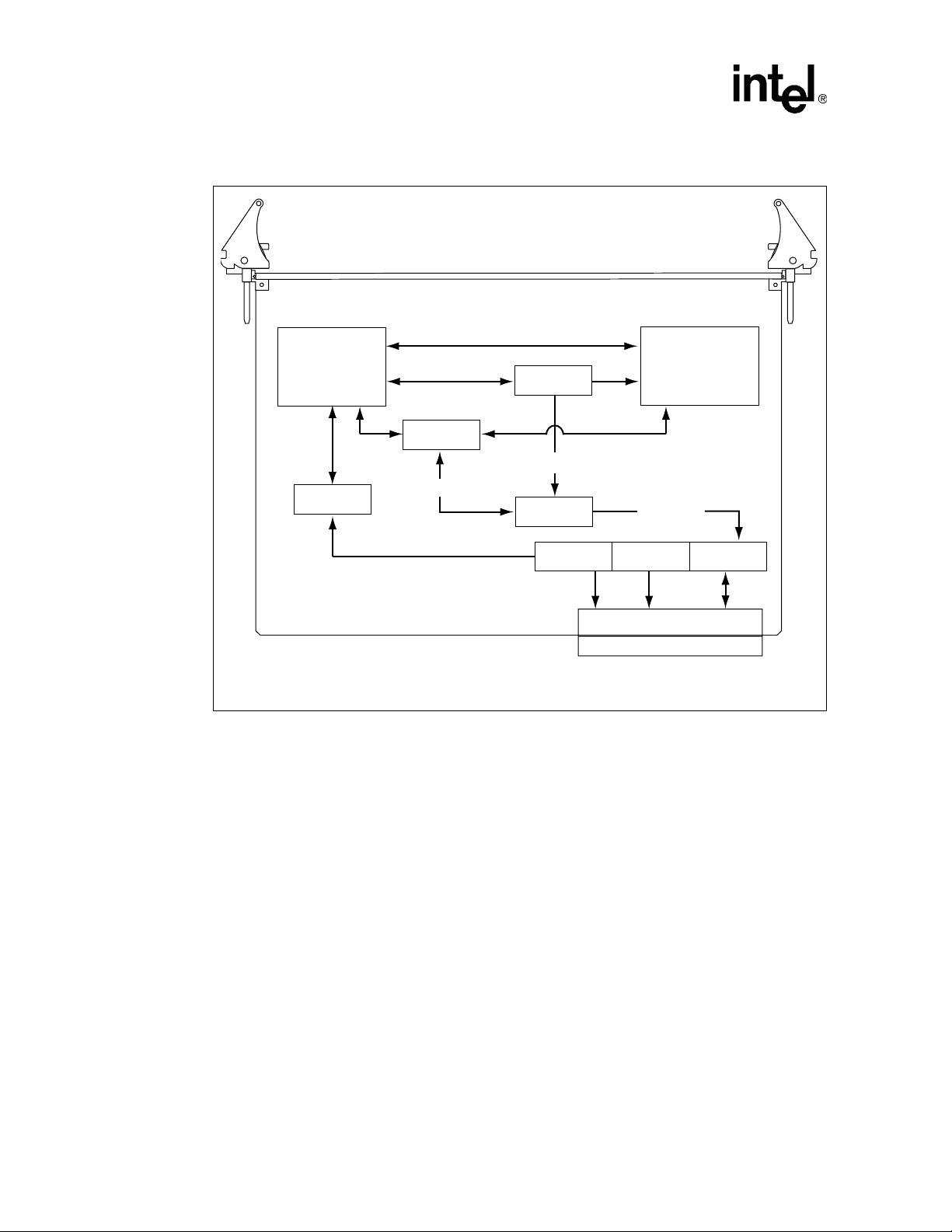
The following figure shows how the basic elements in an HASDK system are related.
Figure 1. High-Availability CPU Architecture
Current Host
OS/Drivers
Hardware
Slot
Control
Driver
Slot
Controller
Comm
Driver
Slot
Comm
Controller
Application
Backplane
Driver
PCI-to-PCI
Host
Bridge
Application
Hot Swap
Driver
CompactPCI Bus
Host
Driver
CompactPCI
Interface
Controller
RH
Driver
Available Host
RH
Driver
CompactPCI
Interface
Controller
RH Comm
Controller
RH
Comm
Driver
RH
Comm
Driver
RH Comm
Controller
2.1 Terminology
The following terms are commonly used in this document:
Active Host (also known as Current Host, owner, or bus segment owner)—A board is said to
be Active or the Active Host if it is providing System Host functions to the peripherals in a
CompactPCI backplane. This means that it is the Owner of at least one bus segment.
High Availability Software for the Intel® NetStructureTM ZT 4901 Technical Product Specification 11
Page 12

Introduction
Application—Application-specific code, not including application-specific device drivers.
Arbitration—Hardware process of a bus master using the hardware REQ# signal to request the
PCI bus from the Active Host and then being granted access to the bus with the hardware GNT#
signal.
Available Host—A Host operating in Owner mode that can own domains and communicate with
the rest of the RH system. A Host, for example, that it is not switched off or not in some special
mode in which it is isolated from the rest of the RH system.
BP Driver—A backplane device driver is the executable object residing in kernel space that
controls interaction between an application and an instance of a device. For a device driver to be
considered High Availability Aware, it must conform to specific requirements detailed in this
document.
Bus Interface Mode—The mode of the bus segment interface from the CPU base board or the
bridge mezzanine board. The possible bus interface modes are owner mode, drone mode, and
peripheral mode.
Bus master—Any device given peer-to-peer access across the PCI bus to any other master or
target. A bus master must have been granted access to the PCI bus through arbitration.
CIC—The CompactPCI Interface Controller is responsible for coordinating switchovers. It is
generally implemented in programmable logic.
Cluster mode—When two or more Hosts in an HA system are operating in Cluster mode, each
owns a domain and switchover of domain ownership is not allowed.
CMM—The CMM refers to the Chassis Management Module. The Chassis Management Module
maintains the status and control over management devices located inside the chassis.
Cold Switchover— During a cold switchover, bus ownership is transferred from a system master
Host to a receiving Host. The Host receiving bus ownership is then reset, which in turn resets all
the devices that are owned by that Host.
COMM—Ethernet, Media Independent Interface, and so on.
DDK—Driver Development Kit. Software development tools that enable developers to create
device drivers.
Destination Host—The Host that receives the specified domains owned by an Active Host if a
hardware-initiated switchover takes place on the Active Host.
Domain—A collection of peripheral PCI slots that is a Host’s unit of ownership. PCI-to-PCI
bridges can populate these slots, so the domain is generally a collection of PCI trees.
Drone mode (also known as Isolated mode)—A Host operating in Drone mode is isolated from
the backplane.
Failover—A type of switchover that is initiated by the Active Host, resulting from a failure that
leaves the domain in an unknown state and requires a bus segment reset to recover.
Fault-tolerant system—Hardware and software designed with redundancy to achieve very high
availability. Typically this is a h igh-cost High Availability solution.
12 High Availability Software f or the Inte l® NetStructureTM ZT 4901 Technical Product Specificati on
Page 13

Introduction
Handover—A type of switchover that is initiated by the Active Ho st, r e sulting from a software
command or Baseboard Management Controller detected fault wherein the bus segment is
quiesced before the transfer of system slot functions.
HA SDK—High Availability Software Development Kit
High-Availability (HA) system—Constructed from standard components with redundancy to
reduce the probability of interruptions. Typically, “five nines” of availability ar e expected
(99.999%).
Host—A Host is a CPU board that is capable of providing system slot functions and System Host
functions to the peripherals in a CompactPCI backplane. This can include any number of bus
segments.
Hot Pluggable—Hot pluggable in the context of this document refers to the driver model used by
devices that reside on the backplane that allows for asynchronous driver suspension and
resumption.
Hot Swap—The term Hot Swap refers to the ability of the hardware and software to work in
conjunction to support the insertion and removal of peripheral boards without requiring the chassis
to be powered-off during the operation.
Hot Switchover—A hot switchover refers to the state of the bus segment that is being inherited by
a newly Active Host. On a hot switchover bus ownership is transitioned and upon unmasking of
backplane interrupts, and enabling of grants, the bus is allowed to operate without any recovery
actions.
Intelligent Platform Management Interf ace (IPM I) —A two-wire electrical bus through which
system- and power-management-related chips can communicate with the rest of the system.
Management Controller—System Management Controller. This may be a Baseboard
Management Controller (BMC), a Satellite Management Controller (SMC) or a Dual Domain
Controller.
Mode Change—A mode change is a change in Host domain ownership characteristics,
specifically, when Hosts change between Active/Active, Active/Standby, or Cluster modes. A
mode change can only occur when all operating Hosts agree through negotiation to change modes.
Owner Mode—A Host operating in Owner mode owns one or more domains. At any given
moment of time, one domain can be owned by no more than one Host. If a Host owns the domain,
software on the Host has access to PCI devices in (or behind) the PCI slots of the domain.
Redundant Host (RH) system—Two or more Hosts that control one or more domains. At any
given instant, no more than one Host can own one domain. If a Host owns th e domain, softwa re on
the Host has access to PCI devices in (or behind) the PCI slots of the domain.
Redundant System Slot (RSS) board—Any CompactPCI board that meets the RSS bus interface
requirements in the CompactPCI Hot Swap Infrastructure Interface Specification, PICMG 2.12.
This includes CPU boards and bridge mezzanine boards.
Segment A Interface—The CompactPCI bus segment interface on the base CPU board.
Segment B Interface—The CompactPCI bus segment interface on the bridge mezzanine.
High Availability Software for the Intel® NetStructureTM ZT 4901 Technical Product Specification 13
Page 14

Introduction
Split Mode—Split Mode is a term that refers to a system operating with multiple system master
Host boards that each own a single bus segment. Split Mode may refer to either Active/Active or
cluster modes. In an Active/Active either of two Hosts can inherit the other Host’s bus segment. In
cluster mode each Host’ s bus segment is locked to that Host and ownership cannot be transferred to
the other Host.
Standby Host (also known as the standby system master)—System board in a High Availability
system that is currently operating in Drone Mode and therefore not the Active Host. The Standby
Host has no visibility of the devices on the other side of the PCI-to-PCI bridge.
Switchover—Changing ownership of a domain from one Host to another.
System Host functions—Central functions provided to a CompactPCI bus segment including hot
swap event response, bus enumeration, and interrupt serv ice. The sys tem slot bo ard pr ovid es these
functions.
System slot—Slot occupied by a System Master that performs arbitration for secondary bus
masters, responds to interrupts from periph eral bo ards , an d dr ives a clock si gn al to each b ackplan e
slot.
Takeover—A type of switchover that is initiated by the Standby Host in a High Availability
system. A takeover may be hostile or friendly.
Warm Switchover—A wa rm switchover refer s to the state of the dom ain that is being inher ited by
the Host taking ownership. On a warm switchover domain ownership is transitioned and, before
any bus actions or operati ons are allow ed to occur, the bus segment is toggled through rese t. This in
effect resets all the devices that reside in the reset domain.
2.2 High Availability Hardware Approach
In an RH system the Redundant System Slot (RSS) subsystem is spread across several building
blocks. These include:
• Processor boards (such as the Intel
• Bridge mezzanine (such as the Intel
• Backplane (such as the Intel
Other building blocks and subsystems may be required to support the RSS subsystem. These
include:
• System management
• Storage
• Power distribution
• Cooling
• Media
®
NetStructure™ ZT 5524 System Master Processor Board)
®
NetStructure™ ZT 4901 Mezzanine Expansion Card)
®
NetStructure™ ZT 4103 Redundant Host Backplane)
• Packet switching
14 High Availability Software f or the Inte l® NetStructureTM ZT 4901 Technical Product Specificati on
Page 15

Intel’s RH software runs on system master processor boards with bridge mezzanine cards in a
PICMG 2.13 compliant RSS backplane to provide redundant system master functionality. This
allows the failover of control of redundant PCI buses. It provides faster hardware that is PICMG
2.9 and 2.16 compliant. The system makes use of the IPMI infrastructure for fault detection and
correction.
2.2.1 Processor Boards
The Host processor board is a CompactPCI system master processor board, such as the ZT 5524,
that can operate in Owner Mode or Drone Mode, and may operate in Peripheral Mode.
Additionally, it must be able to gracefully transition between modes by coordinating with a
Redundant Host (RH). The processor board must also support hot swap when it is in Drone Mode.
The key elements that allow RSS functionality are shown in Figure 2, “RSS Processor Board Block
Diagram” on page 16 and are described below.
PCI The PCI interface to the backplane. This may be a PCI-to-PCI bridge like
the Intel 21154, or some other PCI interface.
Iso/Term CompactPCI termination and isolation. Isolation is require d to ens ure
that the PCI interface does not affect the backplane bus segment when
the board interface is in Drone Mode. Termination is required when the
board interface is in Owner Mode. The isolation may be integrated into
the PCI interface device.
Introduction
Clk The clock generator for the CompactPCI bus segment when the board
interface is in Owner Mode.
CIC The CompactPCI Interface Controller is responsible for coordinating
switchovers.
Arb The bus arbiter for the CompactPCI wh en the board interface is in Owner
Mode.
HC The Host Controller provides the software accessible registers for
control and status of th e CIC.
xMC The IPMI Management Controller may operate as a Baseboard
Management Controller (BMC) or Satellite Management Controller
(SMC). This device is responsible for detecting faults and notifying the
CIC so that it may make the appropriate response. Additionally, the xMC
is responsible for power-on negotiation of bus ownership with a
redundant board.
High Availability Software for the Intel® NetStructureTM ZT 4901 Technical Product Specification 15
Page 16
Introduction
Figure 2. RSS Processor Board Block Diagram
Base CPU Board
CPU/
Chipset
PCI
2.2.2 Bridge Mezzanine
The HASDK driver set works in single and dual bus segment configurations. In order for the dual
bus configuration to be supported a bridge mezzanine must be mounted on the processor board.
HC
Control/Status
Interboard
xMC
Xreq
CIC
Connector
Control
Iso/Term Clk. Arb.
CompactPCI J1/J2
Bus Segment A
The bridge mezzanine is a board that is physically attached to the base processor board. The
processor board and bridge mezzanine are stacked such that they occu py two adjacent CompactPCI
slots.
Like the base processor board, the bridge mezzanine has a CompactPCI bus seg ment interf ace that
can operate in Owner Mode or Drone Mode. The bus interface mode of the bridge mezzanine is
independent of the processor board’s mode.
The bridge mezzanine contains elements that are identical to the base processor board in order to
create a second CompactPCI interface for connection to a different bus segment, as shown in
Figure 3, “RSS Host with Bridge Mezzanine Block Diagram” on page 17.
16 High Availability Software f or the Inte l® NetStructureTM ZT 4901 Technical Product Specificati on
Page 17

Figure 3. RSS Host with Bridge Mezzanine Block Diagram
Introduction
CPU/
Chipset
Control/Status
PCI
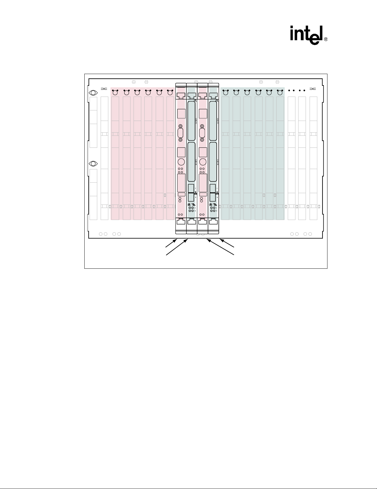
2.2.3 Backplane
The RSS system backplane supports two CompactPCI buses accessible by both Redundant Hosts.
In Active-Standby mode, the active processor board controls the buses (Active Host) and the
standby processor board is isolated from the backplane (Drone mode). By using Active-Activecapable processor boards such as the ZT 5524, the system can be configured so that each p rocessor
board has access to one backplane bus (Cluster mode). The backplane has separate buses for
active-to-standby processor board communication (COMM) and Host Controller functions. See
Figure 4, “High-Availability System Backplane Architecture” on page 18 for an example of a
typical High-Availability backplane.
Base CPU Board
HC
Interboard
Connector
xMC
Xreq
CIC
Iso/Term Clk. Arb.
Control
CompactPCI J1/J2
Bus Segment A
Interboard
Connector
Control/
Status
CIC
Xreq
Bridge Mezzanine
Control
PCI
Iso/TermClk.Arb.
CompactPCI J1/J2
Bus Segment B
High Availability Software for the Intel® NetStructureTM ZT 4901 Technical Product Specification 17
Page 18
Introduction
Figure 4. High-Availability System Backplane Architecture
1A
1B
3 4 5 6 7 8 13 14 18 19 20
2 21
Host Processor Board
Bridge Mezzanine Board
15 16 17
Bridge Mezzanine Board
Redundant Host Processor Board
2.3 High-Availability Software Approach
As shown in the Figure 1, “High-Availability CPU Architecture” on page 11, there are three HighAvailability software components:
• Host application
• System Management
• Backplane Device Drivers
2.3.1 Host Application
The host application serves as the central control mechanism for the platform. For a host
application to function in an RH environment it must be able to relinquis h o r receive contro l of th e
system in a controlled manner. Dynamically transitioning of bus segment ownership between
active and backup requires the application to maintain data synchronization between the
applications on the redundant Hosts.
18 High Availability Software f or the Inte l® NetStructureTM ZT 4901 Technical Product Specificati on
Page 19

The design of the application should be made as portable as possible. This requires that the design
be implemented in a modular approach that isolates the s ystem management requirements from the
host application. This division of responsibilities can be achieved through a layered
implementation. See Chapter 3, “Host Application Sof twar e” for more information.
In addition to taking a modular approach, the application designer should recognize the importance
of producing a hardened application. A hardened application must at least provide a capable
logging mechanism that allows for application faults to be reconstructed and corrected. It should
also adhere to good coding practices such as validating all input parameters and return statuses. A
more proactive approach is to implement fault recovery mechanisms. This could include the
capturing of faults and the isolation of faulted application components.
2.3.2 System Management
Introduction
System management is the mechanism by which system configuration and fault characteristics are
established, insuring system health is maintained. In the Intel
are extensive sets of APIs that provide the developer with a fine level of control of the platform.
The API described in Chapter 6, “Redundant Host API” deals with the management of redundant
hosts that reside in a single chassis. In order to manage such a configuration, a number of function
calls are required so that predetermined default actions can be prescr ibed d epend ing o n the desir ed
switchover strategy. The required functions are based on the Hot Swap Infrastructure Interface
Specification, PICMG 2.12, specifically in the Redundant Host API chapter. The supplied APIs
provide the following abilities:
®
Redundant Host architecture there
• Enumerate the hosts, domains, and slots in the system
• Get information about devices in slots
• Initiate domain switchovers among hosts
• Enable and disable notifications regar ding sw it chov er operati on s
• Specify actions that result from hardware-initiated alarms and control notifications about
alarms.
Chassis management is achieved using the IPMI infrastructure. The IPMI interface exposes the
embedded monitoring devices such as temperature and voltage sensors. Currently there is no
industry standard API for managing IPMI dev ices, primar ily because the devices that are us ed may
vary significantly between chassis configurations. Since the drivers supplied for use in the
Redundant Host architecture are operating system dependant, the interfaces used to access the
IPMI devices are not necessarily portable between the supported operating systems.
The supplied Hot Swap API provides a mechanism to identify the topology and Hot Swap state
within a specified chassis. By using this API the system management application is able to identify
which slots are populated and the power states of the occupying boards. There are additional APIs
that allow for simulated backplane peripheral insertion and extraction. In addition, this API
provides for notification of Hot Swap events.
The Slot Control Interface is independent of the Redundant Host driver. This separation of
functionality is designed to allow for slot control functionality in a chassis without full hot swap or
redundant host capabilities. The Slot Control API is based on the PICMG 2.12 High Availability
Slot Control Interface functions. It interacts with the Slot Control Driver to create IPMI messages
through which a finer granularity of board control can be achieved then was found in previous
generations of High Availability systems. Using the Slot Control API the application can retrieve
information regarding “Board Present Detection”, “Board Healthy”, and “Board Reset” capability.
High Availability Software for the Intel® NetStructureTM ZT 4901 Technical Product Specification 19
Page 20

Introduction
2.3.3 Backplane Device Drivers
Backplane device drivers are a critical component of High A vailability system. The drivers need to
be robust in their operations as well as to be dynamic given the “Stated” nature of a Hot Swap
architecture.
The ability of a driver to remain loaded and initialized even though the Host may not have visibility
to the device is critical when Host ownership transfer can occur almost instantan eously. In order for
a driver to function in this environment the designer should implement the driver in a stated
fashion. This means that the driver must be able to be started and stopped asynchronously.
Another important factor when designing a driver that will function in a Redundant Host
environment is the ability to maintain synchronization between redundant device drivers that reside
on separate Hosts. In order to provide an easily implemented communication mechanism the Intel
HASDK provides a single callback definition and API call. This driver communication mechanism
enables not only a simple interface, but because of its simplicity, a very robust synchronization
tool.
The Intel Redundant Host architecture also provides support for those devices that require a
domain reset. The domain can be reset by using either of the following methods:
• The default IPMI settings. These can be configured using the IPMI API, described in
Chapter 8, “IPMI API.”
• The Redundant Host API using either the Switchov er or Slot Informati on APIs, as d escribed in
Chapter 5, Chapter 6, “Redundant Host API.”
For more information regarding the Hot Swap and Redundant Host CompactPCI device driver
design model see Chapter 5, “High Availability CompactPCI Device Drivers.” Redundant Host
APIs and callback definitions for specific operating systems are in Appendix C, “HSK Device
Driver Interface for VxWorks* 5.4,” and Appendix D, “RH Device Driver Interface for Linux*
2.4.”
20 High Availability Software f or the Inte l® NetStructureTM ZT 4901 Technical Product Specificati on
Page 21

Host Application Software 3
Through thoughtful design and the use of a layered development approach, an application can be
developed that meets the implied robustness of a highly available system and also is a portable
entity. In addition to covering the details of developing an application that runs in a High
Availability environment, this chapter provides a foundation for unde rstan ding the issues that a
developer needs to be aware of when deploying in a multi-host architecture.
3.1 Goals of the Host Application
Design goals that should be achieved for your application to perform successfully in a High
Availability environment are:
• Serviceability
• Portability
• Redundancy
3.1.1 Serviceability
The first and probably most important attribute of an application is to maintain a constant level of
service. This ability to provide a minimum level of functionality is referred to as serviceability. The
concept of serviceability should not be restricted to performing the required functionality within
the domain of a single Host, but should be considered at a much higher level. An app lication is the
service or set of services that need to be performed within the domain o f a platform. By domain we
are referring to the system that is providing the service. The system could be as simple as a system
master processor board, but more than likely the system will contain peripheral boards, chassis
management modules, various system sensors, and in the case of a redundant host architecture,
multiple system master boards.
3.1.2 Portability
Another goal is to design and implement a portable Host application. Some of the largest
investments that a provider makes are in the areas of application development and maintenance. In
order to preserve as much of the initial investment as possible, it is important to design the
application so that it is separated from specific platform components that may be enhanced or
changed. Portability can be achieved by isolating the application as much as possible from the
system management responsibilities required for High Availability. This separation of functionality
can be achieved through a combination of modular design and a layered software approach. This
topic is covered in more detail in Secti on 3.2, “Division of Labor” on page 22.
3.1.3 Redundancy
In order to achieve a high level of serviceability within a Redundant Host environment, it is
assumed that the host application has the ability to failover to another application. This backup
application should be a mirrored copy of the original application that will likely reside on another
High Availability Software for the Intel® NetStructureTM ZT 4901 Technical Product Specification 21
Page 22
Host Application Software
System Host in the same chassis. In order for a host application to be capable of maintaining the
system’s serviceability, these redundant applications should maintain some level of
synchronization. The level of synchronization and the level of sophistication of the system’s
peripherals determine the failover characteristics of your system. Synchronization issues, in
addition to other implementation concerns, are covered in the Section 3.3, “Development Issues”
on page 23.
3.2 Division of Labor
Historically, embedded application developers have i ntegrat ed the manag ement of th e syst em wit h
the host application. This tight integration meant it was unlikely that much of the host application
could be ported when the application was rehosted on a new platform. This topic presents a
possible architecture that allows the host application to remain aware of system performance and
degradation while maintaining a loose coupling with the system managem ent as pects of th e
architecture.
One of the keys to portability in application design is to maintain a modu lar design. This goal is
often complicated by routines used for system manage ment that place particular requirements upon
the implementation of the application. One way to reduce the awareness of the application on a
particular implementation is to take a layered approach to the design of the application. In this way
you can reduce specific implementation features without unnecessarily isolating the application
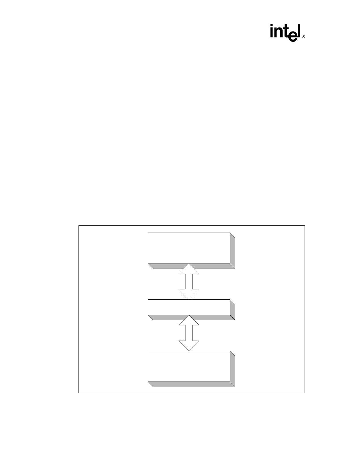
from the underlying performance of the system. See the “Layered Host Application Diagram”
below.
Figure 5. Layered Host Application Diagram
Host Application
Platform Interface
System Management
Modules
22 High Availability Software f or the Inte l® NetStructureTM ZT 4901 Technical Product Specificati on
Page 23

Host Application Software
The diagram shows that the host application’s need to understand the particular implementation
aspects of the platform’s system management is reduced by placing an intermediary layer that in
effect interfaces and translates only the system management information that the host application
cares about. The host application should usually care about only those issues that would degrade
performance or cease operations, such as:
• Access to peripherals
• System performance
• Integrity of operations
The platform interface can be more than a wrapper around exposed system functionality: It could
act as a filter with a level of intelligence. The platform interface could be designed so that the
module could monitor system health and take proactive actions like initiating a handover, when
circumstances dictate. The platform interface might also be responsible for translating systemparticular messages and alerts into a normalized format that the application understands. The
events that a host application most likely requires notification of are:
• Switchover situations
• Warnings of system failures
• The availability of system resources
All these events should be handled first by the platform interface and relayed to the host
application only when they might impede performance.
3.3 Development Issues
There are several issues that an application developer of a High Availability system architecture
must be aware of:
• Redundancy
• Graceful switchover
• Hardened applications
• Code modularity
3.3.1 Redundancy
Redundancy, or at least the awareness of redundancy, must be designed into the application. This
requires that data be constantly normalized. The term data could mean anything from state
information to an entire database. The ultimate goa l is to have a system that appropriately res ponds
to a switchover while maintaining the integrity of all system data.
The trade-off for maintaining a high level of synchronization is required overhead. The amount of
bandwidth required for data normalization can be effectively reduced by:
• Utilizing intelligent peripherals that internally maintain state
• Creating innovative methods of database sharing through shared RAID architectures
These are just examples of data synchronization; there are numerous ways to share data that are
dependant on your actual implementation.
High Availability Software for the Intel® NetStructureTM ZT 4901 Technical Product Specification 23
Page 24

Host Application Software
3.3.2 Graceful Switchover
In a Redundant Host environment a graceful switchover is only secondary in importance to data
integrity. An effective mechanism is required in order for an application to seamlessly pick up the
functionality of a faulted application. The Intel Redundant Host environment has an infrastructure
in place to help facilitate such control transitions. This architecture supplies:
• Multiple communication paths
• A capable fault detection interface
• Embedded firmware that can be configured for multiple failover scenarios
In addition to providing a fine level of granularity on the type of switchovers provided, this
platform also exposes these switchover events to an application or platform interface module so
that the software can act upon the events appropriately.
3.3.3 Hardened Applications
In almost all environments it is important to develop applications in a hardened manner, but in a
highly available embedded environment it is especially important. The definition of the term
“Hardened” may vary depending on the type o f system that is being dev eloped and the accessibi lity
of various system level software components. In the context of this Redundant Host architecture,
the term hardened refers to verifying that all function return codes are appropriately handled and
dispatched with accordingly, function parameters are validated, and that the system maintains a
logging mechanism sufficient to monitor system performance and to assist in diagnosing fault
conditions when present. Code hardening should be part of any standard development effort, but a
disciplined approach to code hardening must be maintained in an HA environment.
3.3.4 Code Modularity
Code modularity is also considered a common implementation characteristic, but it is often
overlooked during the implementation portion of a project. In order to achieve some level of
application portability the designers need to make the conscience effort to move away from typical
embedded monolithic designs.
One approach to modular design in an HA architecture is to decouple the services provided by the
system from the entities responsible for system management. Since system management is heavily
dependant on the hardware configuration of the host platform, the implementation of a platform
interface module helps to abstract the host application away from the platform on which it resides.
The Platform Interface Module achieves platform abstraction by handling most hardware level
monitoring and exposing platform specific interfaces only through non-proprietary APIs. One of
the advantages of the Intel High Availability Redundant Host System is the reliance on industrystandard, non-proprietary interfaces. These interfaces allow for future portability of the developed
code base.
24 High Availability Software f or the Inte l® NetStructureTM ZT 4901 Technical Product Specificati on
Page 25

System Management 4
System Management is an all-encompassing term whose definition can vary drastically depending
on the type of system that is being developed. System Management can indicate anything from
system configuration all the way to active reporting, proactive fault remediation, and
comprehensive system security. In a relatively closed system with limited access to external
interaction, system management could be limited to chassis ma nagement, event logging, and
resource management. In systems that require more sophisticated external interface and a finer
granularity of control, system management mechanisms can provide a myriad of APIs and system
services for administering a system.
The intent of this section is to give a developer an overview of what application programming
interfaces are supplied by the High Availability SDK (HASDK).
The HASDK provides System Management capable APIs. The APIs enable Redundant Host
configuration and administration, IPMI infrastructure communication and administration, Hot
Swap device detection and management, Slot Control for control and access of backplane slot
attributes.
Most of the details for creating and administering a Telco based solution are beyond the scope of
this document.
4.1 Redundant Host API
Among these APIs is a PICMG* 2.12 compliant Redundant Host Programming Interface. This
interface allows a client to perform the following operations:
• Initialize and terminate an instance of this interface
• Enumerate the Hosts, domains and slots in the system
• Get information about devices in slots
• Initiate domain switchovers among Hosts
• Enable and disable notifications regar ding sw it chov er operati on s
• Specify actions that result from hardware-initiated alarms and control
See Chapter 6, “Redundant Host API,” for more information.
4.1.1 IPMI API
Platform management is a major component of a com preh ensiv e sys tem man agemen t architectur e.
Platform management allows for status and event notification of all exposed interfaces such as
temperature sensors, voltage monitors, and other sensory devices. These status and
communications capabilities need to be as extensible as possible.
High Availability Software for the Intel® NetStructureTM ZT 4901 Technical Product Specification 25
Page 26

System Management
The next-generation, high-availability architecture provides this system management infrastructure
using IPMI. Through the IPMI API the developer is able to access the status of individual sensors,
various management controllers, and to configure the system to initiate switchovers based on
events or threshold excursions. See Chapter 8, “IPMI API,” for details.
4.1.2 Hot Swap API
A critical feature of any system that claims to be Highly Available is the capability to perform
peripheral insertions and extractions without requiring that the system be powered off. In order to
provide this functionality a kernel level Hot Swap infrastru cture should be integrated into the
operating system. This infrastructure allows for dynamic resource allocation for peripheral slot
cards. Given the dynamic nature of a Highly Available platform, the system management needs to
remain aware of the system’s topology. A PICMG 2.12 compliant Hot Swap API accomplishes
this. The Hot Swap API includes functions to return the state and population of the CompactPCI
bus, to simulate unlatching a particular board's hot swap extractor, and to permit software
connection and disconnection. See Chapter 6, “Redundant Host API,” for more information.
4.1.2.1 Slot Control API
Another part of system management is the ability to control individual peripherals car ds . Under
normal circumstances in which a system is operating properly, little in the way of card control
needs to be performed. There are events that require actions to be taken to place the peripheral
cards into a known state. It is the respo nsibility of the sl ot control driver and the accompany ing API
to provide this quiescing and peripheral shutdown functionality. This API provides control at the
card level, as well as providing several functions that allow reporting the status of the peripheral
card’s operational state. See Chapter 9, “Slot Control API,” fo r more inf orm ation.
4.2 Baseboard Management Controller Firmware Enhancements
The HASDK takes advantage of the system master processor board’s capability for board
management provided through its resident Baseboard Management Controller (BMC). The
standard capabilities of the BMC provide a high level of system management. To support RH
functionality, some extensions for bus segment control are added to IPMI v1.5 specification
support. These extensions include:
• Fault Configuration
• Isolation Strategies
• CompactPCI Interface Controller interaction
• Non-Volatile Storage of RH Parameters
• IPMI RH Channel Commands
4.2.1 Fault Configuration
The BMC handles the following event triggering mechanisms for each entry in its Sensor Data
Record (SDR):
• Upper/Lower non-critical threshold
26 High Availability Software f or the Inte l® NetStructureTM ZT 4901 Technical Product Specificati on
Page 27

• Upper/Lower critical threshold
• Upper/Lower non-recoverable threshold
Each range can be set independently for each sensor and the ranges can overlap. This area of
configuration is used only to trigger events. These events appear in the System Event Log.
Platform Event Filtering (PEF) determines the actions that occur as a result of these events. Only
the Upper/Lower non-recoverable threshold is typically configured using the PEF to cause a
hardware-initiated takeover to occur.
4.2.2 Isolation Strategies
The BMC handles the following event actions in its PEF Table:
• Alert
• Power Off
• Reset
• Power Cycle
• Diagnostic Interrupt (NMI)
These options can be set independently for each event.
System Management
Support for a Handover action allows the takeover / handover p rocess to occur from the B MC. This
action triggers the CompactPCI Interface Controller (CIC) to initiate the handover sequence. A
virtual RH channel facilitates this switchover request.
T a ble 1. Channel Definitions for ZT 5524
Channel # Description
0x0 IPMB 0
0x1 EMP
0x2 ICMB
0x3 PCI
0x4 SMM
0x5 RH Virtual Channel
0x 6 LAN Inte rface 2
0x 7 LAN Inte rface 1
0x 8 IPMB 1
0x 9 RESERVED
0xA RESERVED
0xB RESERVED
0xC Internal
0xD RESERVED
0xE Self
0xF SMS
High Availability Software for the Intel® NetStructureTM ZT 4901 Technical Product Specification 27
Page 28

System Management
Table 2. RH Channel Alert Destinations
Destination # Description
0x00 RESERVED
0x01 RH_CHAN_SET_ALL_MC_FD (Sets CIC Fault Detection Lines)
0x02 RH_CHAN_CLEAR_ALL_MC_FD (Clears CIC Fault Detection Lines)
The RH channel acts as a virtual channel that can respond to Alert Actions. This channel supports
IPMI commands like Alert Immediate:
• In the Alert Policy Table: Create an entry with a unique policy number, channel specified as
RH, destination specified as RH_CHAN_SET_ALL_MC_FD.
• In the Platform Event Filter Table: Create an entry with the Alert action selected, Alert Policy
Number defined as above, and the data mask specified based on the sensor thresholds to be
triggered.
4.2.3 IPMI RH Channel Commands
The following RH commands are present in the ZT 5524 processor board BMC firmware. These
are accessible only by sending the selected command/net function to the RH channel (0x05)
4.2.3.1 RH Channel Enabled
This IPMI command returns whether the board has RH features enabled o r not. Conditions for nonRH operation are: No IOX presence or the board is in a non-RH capable slot. Standard IPMI
completion codes are returned.
IPMI Command: RH_CHAN_ENABLED (0x00)
Net Function: INTEL_RH_SPECIFIC_REQUEST (0x36)
ByteData Fields
Request Response 1 Completion Code
2 1h = RSS enabled
-
0h = RSS disabled
4.2.3.2 RH Channel Get RH BMC Address
This command gets the IPMB 1 address of the redundant host’s BMC. Standard IPMI completion
codes are returned.
IPMI Command: RH_CHAN_GET_RH_BMC_ADDR (0x05)
Net Function: INTEL_RH_SPECIFIC_REQUEST (0x36)
ByteData Fields
28 High Availability Software f or the Inte l® NetStructureTM ZT 4901 Technical Product Specificati on
Page 29

Request - Response 1 Completion Code
2 RH BMC Address
System Management
High Availability Software for the Intel® NetStructureTM ZT 4901 Technical Product Specification 29
Page 30

System Management
This page intentionally left blank.
30 High Availability Software f or the Inte l® NetStructureTM ZT 4901 Technical Product Specificati on
Page 31

High Availability CompactPCI Device
Drivers 5
This chapter describes the characteristics of highly available software drivers for CompactPCI
peripherals in a Redundant Host environment.
To fully utilize the High Availability SDK, you must write a peripheral driver that can be started
and stopped repeatedly and that can be lo aded and in itialized even when the d evice it is ser vicing is
not physically visible to the operating system.
5.1 Device Driver Design
Historically, device drivers are relatively simple in their high level requirements. The operating
system detects a hardware component and loads a module of software that allows softwareinitiated interaction with the hardware. It was assumed that the hardware configuratio n would not
change over the life of the system, or at the least would remain static between power cycles.
With the advent of CompactPCI these assumptions can no longer be guaranteed. One of the
primary advantages of a CompactPCI architecture is the ability to perform peripheral insertions
and extractions without requiring the chassis to be powered down. This system attribute is referred
to as Hot Swap. Because of this, system configurations can no longer be assumed to be static. This
dynamic configuration capability places new requirements on the operating system and the Hot
Swappable device drivers.
The operating system kernel now needs to be able to dynamically handle system resources, in
allocation and resource collections. Intel supplies a Hot Swap manager for operating systems
supported by the Intel
operating system kernel that manages dynamic bus and resource allocations. Since this is a kernellevel function that is transparent to the developer, this document will not describe the details of this
module.
In order for a device driver to function in a Hot Swap environment, the driver is required to
implement what is known as a Stated Driver Model. A stated device driver is constructed in a
manner that allows it to gracefully transition between multiple operational modes.
The specifics of stated device driver design vary for each operating system supported. This is due
to the Hot Swap implementation that is used by each operating system. If an operating system
natively supports Hot Swap events then the driver implementation will leverag e the supported
driver model.
This is the case with Linux* kernel version 2.4. Refer to Appendix D, “RH Device Driver Interface
for Linux* 2.4” for more informat ion.
VxWorks* version 5.4 does not natively support a stated driver model, so Intel has provided
enhancements to this operating system. The specifics of the VxWorks CompactPCI driver model
can be found in Appendix C, “HSK Device Driver Interface for VxWorks* 5.4.”
®
High Availability architecture. This manager is a component of the
High Availability Software for the Intel® NetStructureTM ZT 4901 Technical Product Specification 31
Page 32

High Availability CompactPCI Device Drivers
5.1.1 Device Dri ver States
There are varying degrees of functionality that are dependent on power modes, operating system
Hot Swap implementations, and device characteristics. But for a device driver to function in this
High Availability architecture we can generalize the required driver states down to thr ee dist inct
states.
• Initialization
• Quiesced
• Activation
5.1.1.1 Initialization
During initialization, the driver starts up and is loaded. The driver cannot “talk” directly to the
hardware devices it is controlling, with the exception of PCI configuration cycles. Intel has
provided the ability to perform PCI configuration cycles to any backplane devices even if the
device driver resides on the Standby Host.
5.1.1.2 Quiesced
A quiesced device driver is completely initialized with all internal allocations and instantiations of
device information completed, ready to perfo rm direct dev ice operations . A device driver waits for
notification from the Hot Swap Manager via a Start or Resume callback mechanism, indicating that
the driver is free to access the device directly. The driver must be designed to transition between
Quiesced and Active states at any time.
5.1.1.3 Activation
Device activation notifies the driver that the system master is in the Active state; direct device
interaction is permitted. When a device driver receives a Stop or Suspend callback, the driver must
clean up any device-specific state information and transition to a known or Quiesced state.
32 High Availability Software f or the Inte l® NetStructureTM ZT 4901 Technical Product Specificati on
Page 33

Figure 6. Multi-Stated Driver Flowchart
High Availability CompactPCI Device Drivers
AddDevice
Driver
Not Loaded
RemoveDevice /
Find
Suitable
Driver
Device
Removed
SurpriseRemoval
StopDevice StartDevice
Device Not
Present
RemoveDevice /
SurpriseRemoval
5.1.2 Adding High-Availability Functionality
Operating in a Redundant Host architecture places additional responsibilities on device drivers
beyond those issues required to function in a normal Hot Swap environment. This section covers
particular issues that a Redundant Host device driver designer needs to be aware of when
implementing their design.
Device
Suspended
Device
Running
The Redundant Host architecture leverages the Hot Swap driver interface to enable Ultra-Quick
switchovers. To do this the Hot Swap Manager views a domain ownership change as a multi-card
Hot Swap event. When a Host loses ownership of a bus segment its Hot Swap Manager issues a
stream of stop device messages that attempts to place the backplane devices into a known quiesced
state. The device drivers on the Destination Host are in a known state. By us ing the describ ed High
Availability driver model the Destination Host devi ce driv ers are able to as sume control in an
almost instantaneous manner.
Additional measures need to be taken to protect against inadvertent backplane interrupts and busmastering activities by devices on the segment in question. These additional measures are
completely transparent operations to the device drivers since the Hot Swap Manager in the kernel
handles them. All a device driver needs to be concerned with is being able to gracefully suspend
and resume interaction with the device or devices it controls.
Each operating system that supports Hot Swap does so in a unique way. The specific function
callbacks, number of callbacks, and level of control vary between operating system
implementations. However, all Hot Swap implementations are based on the stated driver model
described in Section 5.1.1, “Device Driver States” on page 32. The driver states can be classified
into the following generic functions:
High Availability Software for the Intel® NetStructureTM ZT 4901 Technical Product Specification 33
Page 34

High Availability CompactPCI Device Drivers
• Add Device
• Resume Operations
• Suspend Operations
• Remove Device
5.1.2.1 Add Device
Add Device is the device driver call made by the Hot Swap Manager either when an asserted
ENUM signal is detected or during the kernel load time. The Add Device callback execution
indicates to a device driver that an instance of a device that the driver can control has been
detected. The driver should perform any internal structure initialization, but should not attempt to
initialize the device.
This is where device driver design on a Redundant Host architecture capable device branches from
common device driver practices. Normally du ring the Add Device callback the driver initializes the
device. During the Add Device execution in a Redundant Host architecture, the device cannot be
assumed to be physically visible to the Host making the Add Device call.
The Intel
that provides the Host with the ability to query the configuration of backplane devices, whether or
not the devices are physically visible. In this manner a device driver can query the information
required to allocate the appropriate resources. Any operations that require direct access to the
backplane device may only occur in the Resume Operations and Suspend Operations callbacks.
®
Redundant Host architecture supplies a PCI Configuration Space Spoofing mechanism
5.1.2.2 Resume Operations
The kernel calls the Resume Operations function only when the Host has visibility of the
CompactPCI backplane device. It is during this operation that the device driver can perform direct
device accesses. This may entail initializing the device, querying current device status, or simply
placing the device into a known state. It is normally in the Resume Operations callback that the
Interrupt Service Routine (ISR) is connected or chained to the appropriate interrupt signal.
As stated earlier, to the driver should not attempt to access a device unless the Host has physical
visibility to the device. If an access is attempted to a non-owned or non-visible CompactPCI device
then a system crash may occur.
This also applies to kernel accesses to non-visible devices. An example of this is if the kernel
detects an interrupt and executes the ISRs attached to what could be a shared interrupt signal. The
device driver normally does this by quer ying the controlled dev ice. If the device is not visible to the
querying Host, then a system crash may occur.
Two ways to help protect against this situation are:
1. Connect the device driver’s ISR only when the Resume Operation callback is executed
2. Make a sanity check at the top of the ISR to see if the device is visible to the executing Host.
The Intel HA SDK provides a kernel level query function that can be used by device drivers to
determine if the Host controls the bus segment on which the CompactPCI device resides.
34 High Availability Software f or the Inte l® NetStructureTM ZT 4901 Technical Product Specificati on
Page 35

5.1.2.3 Suspend Operations
The counterpart to the Resume Operation callback is the Suspend Operation. The kernel calls the
Suspend Operation callback function for each d evice f or which a Host is losing visibility . I t cann ot
be assumed that the driver retains visibility to the backplane device during the Suspend Operation
execution. The Suspend Operatio n should first disconnect the device’s interrupt service routine.
The driver should then do whatever normalizing of internal device structures is required so that, if
necessary, the driver will be in a position to inherit control of the device again.
5.1.2.4 Remove Device
The Remove Device function is called when a CompactPCI backplane device is extracted from the
chassis. It is in this routine that all structures that were created and/or initialized during the Add
Device call are deallocated. All internal cleanup of the extracted device needs to occur with the
awareness that the driver cannot assume visibility to the device. This is not a major issue since the
Hot Swap event detected and ENUM remediation occurs in the Hot Swap Manager, which is
transparent to the device driver.
5.1.2.5 Driver Synchronization
Redundant Host aware device drivers mi ght need t o handle dr iver synch ronizati on. In a Re dundant
Host architecture two device drivers are assigned to control a single device. Device control may be
transitioned from one Host to the other at any moment so the device driver needs to be dynamic in
its design.
High Availability CompactPCI Device Drivers
Part of this dynamic state capability is made more manageable through inter-Host synchronization.
In this case the synchronization mechanism is an inter-Host communications channel. The interdriver synchronization infrastructure can be used for various synchronization strategies; among
these are data mirroring, check pointing, and device heart beating.
The Intel HA SDK has defined a Receive Message callback and a Send Message API routine. The
kernel executes the Receive Message callback whenever a message is destined to a backplane
device driver from the reciprocating driver on the opposite Host. The contexts of these
synchronization messages are transparent to both the sending and receiving Hosts. The messages
themselves are decoded and used internally by the receiving device drivers. There is a possibility
that the message received is no longer valid for the following reasons:
• The system masters are not run in lockstep and do not access shared memory
• A delay can occur between the time a message is sent and the time the device driver is able to
consume the message
To minimize this possibility of bein g out of sync, the drivers should limit themselves to
synchronizing mostly st ate or datab ase re lated infor mation. F or examp le, a device d river may w ant
to share the usage of a specific IP address across Redundant Hosts. In this case a driver packages
up the IP address and uses the Send Message API to transmit the packet to the Redundant Host.
The Receiving Host decides which device driver is to receive the packet and calls the registered
Receive Message callback routine. The device driver then decodes the message packet
appropriately.
High Availability Software for the Intel® NetStructureTM ZT 4901 Technical Product Specification 35
Page 36

High Availability CompactPCI Device Drivers
5.2 Summary
The intent of the HA CompactPCI device driver model is to leverage the native device driver
infrastructure to supply a robust Hot Swap capability while limiting the non-proprietary device
driver modifications. In order for a device driver to function effectively in a Redundant Host
environment the driver should at a minimum implement the Hot Swap device driver infrastructure
detailed in the following appendices of this manual:
• Appendix C, “HSK Device Driver Interface for VxWorks* 5.4”
• Appendix D, “RH Device Driver Interface for Linux* 2.4”
The specific implementation details vary between the supported operating systems, so choose the
correct driver model for the operating system for which you are developing. To best leverage the
Redundant Host capabilities it is recommended that some level of synchronization be implemented
using the supplied device driver messaging infrastructure.
It is not necessary to implement all the supplied Redundant Host features for backplane device
drivers to function in a High A vailability architecture. There are some device implementations that
require a device or bus segment to be reset when Host ownership changes. Using either the
PICMG* 2.12 Redundant Host API or the IPMI API system information extension documented in
the next chapter allows the bus segment to automatically reset the specified domain after the new
Host has inherited the bus segment. To use these functions, see the Redundant Host switchover and
slot information related APIs and the IPMI API for default Host activities.
36 High Availability Software f or the Inte l® NetStructureTM ZT 4901 Technical Product Specificati on
Page 37

Redundant Host API 6
6.1 Intel-Specific APIs
6.1.1 RhSetHostName
Prototype:
RH_API_DEF HSI_STATUS
RhSetHostName(
IN RH_HANDLE Handle,
IN uint32 Host,
IN char HostName[ ])
Arguments:
Handle - The handle of the current session
Host - The host number
HostName - The character buffer where the host name is stored as a 0-terminated
character string
Return V alue:
HSI_STATUS_SUCCESS - returned in the case of success
RH_INVALID_HANDLE - invalid session handle
HSI_ST ATUS_NOT_SUPPORTED - returned if this function is not supported by the infrastructure
Other HSI_STATUS values - if errors occurred during execution of this function such as
nonexistent host
Synopsis:
This function sets the symbolic name of the specified host; this should be some kind of network
name (for example, NETBIOS name or TCP/IP host name) that can be used to establish a network
connection to that host.
6.1.1.1 RhGetHwDestinationHostAndReset
Prototype:
HSI_STATUS
RhGetHwDestinationHostAndReset(
IN RH_HANDLE Handle,
IN uint32 So urceHost,
IN uint32 Domain,
OUT uint32 *pDestinationHost,
High Availability Software for the Intel® NetStructureTM ZT 4901 Technical Product Specification 37
Page 38

Redundant Host API
Arguments:
Handle – the handle of the current session
SourceHost - the number of the source host
Domain – the domain number
pDestinationHost pointer to the variable receives the number of the host that should own
pbReset pointer to the variable receives the state of the flag that indicates whether
Return Value:
HSI_STATUS_SUCCESS
HSI_STATUS_INVALID_PARAMETER
OUT BOOL*pbReset );
the specified domain if the source host fails and hardware-initiated
switchover takes place for it
the specified destination host will perform a reset if the host receives
control of a segment
returned in the case of success
invalid session handle or the specified domain does not exist
HSI_STATUS_NOT_SUPPORTED
returned if this function is not supported by the infrastructu r e
Other, implementation-defined HSI_STATUS values
returned if other errors occurred during execution of this function
Synopsis:
This function gets the destination host that owns the specified domain and the reset flag value if a
hardware-initiated switchover takes place due to the failure of the source host.
6.2 Redundant Host PICMG* 2.12 APIs
This chapter describes a supplementary API for domain management and switchover from the
application level.
The interface described in this section is implemented as a set of functions exported to an
application.
These functions allow the client to perform the following operations:
• Initialize and terminate an instance of this interface
• Enumerate the hosts, domains and slots in the system
• Get information about devices in slots
• Initiate domain switchovers among hosts
• Enable and disable notifications regarding switchover operations
• Specify actions that result from hardware-initiated alarms and control notifications about
alarms
38 High Availability Software f or the Inte l® NetStructureTM ZT 4901 Technical Product Specificati on
Page 39

The following topics specify each of the interface functions.
6.2.1 Definitions and Types
The following definitions are provided for terms used in the remaining topics of this chapter.
RH (Redundant Host) System. An RH system consists of two or more hosts and one or more
domains. An ownershi p relati onsh ip is d efined b etween ho sts and d omain s: ho sts ow n domain s. At
any given moment of t ime, no more than one host can ow n on e d omai n. If a host owns the domain,
software on the host has access to PCI devices in (or behind) the PCI slots of the domain.
RH (Redundant Host) Infras truct u re. An RH Infrastructure is an implementation of the Redundant
Host PICMG 2.12 APIs for a specific RH System. It provides the Redundant Host API defined in
this topic to applications. Multiple RH Systems of the same type may be serviced by a single
infrastructure.
Domain. A Domain is a specific collection of peripheral PCI slots whose ownership can be
transferred as a group among system hosts. PCI-PCI bridges can populate these slots. Therefore, a
domain is generally a collection of PCI trees (a forest). Domains in the system are identified by 32bit arbitrary quantities – domain numbers. The number of domains in the system and their domain
numbers are assumed static during system operation.
Redundant Host API
Host. A Host is an active entity in the system that can run software that uses this API. Hosts in the
system are identified by 32-bit arbitrary quantities – host numbers. The number of hosts in the
system and their host numbers are assumed static during the system operation. The host number
RH_NO_DESTINATION_HOST means “no host” and is used, for example, to say that no host
owns the specified domain.
Domain parent bridge. A PCI-PCI bridge is called the parent for a domain if all slots behind that
bridge belong to that domain and all slots of the domain are behind that bridge.
Domain slot path. The slot path for a PCI device is the sequence of device/function numbers from
this device up the PCI tree to its root through the sequence of PCI-to-PCI bridges. Usually (but not
necessarily) each domain has a domain parent bridge. When a host owns the domain, the slot path
of the domain parent bridge is the domain slot path with respect to the host. Domain slot path may
be defined with respect to a host even if that host does not own the domain, provided that the
domain is guaranteed to have the same slot path each time it is switched over to that host.
Switchover. Switchover is changing ownership of a domain from one host to another.
Destination Host. This is the host that receives the specified domains owned by a particular host if
a hardware-initiated switchover takes place on the owning host.
Avai labl e Hos t . A ho st is available if it can o wn do mains and commu nicate with the rest of th e RH
system. A host is unavailable, for example, if it is switched off or is in some special mode in which
it is isolated from the rest of the RH system.
Owning Host . The host that currently owns a domain.
Current Host. The host on which the specific API call has been made.
Root Bus. The root bus number of the PCI tree this slot belongs to. This value is 0 for the first or a
single PCI tree. For additional PCI trees, this value is implementation-dependent, but is guaranteed
to be non-zero.
High Availability Software for the Intel® NetStructureTM ZT 4901 Technical Product Specification 39
Page 40

Redundant Host API
RH Instance ID. A host can be a member of several RH systems simultaneously, similar to multihomed hosts in networking. In that case, the application can use the Redundant Host API from
several RH infrastructures. To select a specific RH system, the application uses the RH Instance ID
when obtaining the handle to the RH system via RhOpen. RH Instance ID is an implementationdefined character string. To allow potential coexistence of multiple RH infrastructures on the same
host, the RH Instance ID should consist of the RH infrastructure identifier and the identifier of a
specific instance of the RH system (if multiple RH System instances are serviced by a single
infrastructure).
The C definition of the associated types used by this interface is given below:
typedef enum {
INACTIVE,
DISCONNECTED,
DISCONNECTING,
CONNECTED,
CONNECTING } RH_DOMAIN_SWC_STATE;
typedef enum {
MINOR_ALARM,
MAJOR_ALARM,
CRITICAL_ALARM } RH_ALARM_SEVERITY;
typedef enum {
ACTION_IGNORE = 0,
ACTION_NOTIFY = 1,
ACTION_SWITCHOVER = 2,
ACTION_RESTART = 4 } RH_ALARM_ACTION;
typedef enum {
NOTIFICATION_DOMAIN_STATE_CHANGE,
NOTIFICATION_SWITCHOVER,
NOTIFICATION_SWITCHOVER_REQUEST,
NOTIFICATION_UNSAFE_SWITCHOVER,
NOTIFICATION_ALARM } RH_NOTIFICATION_TYPE;
typedef enum {
FULLY_COOPERATIVE,
PARTIALLY_COOPERATIVE,
FORCED,
HOSTILE,
HARDWARE_INITIATED } RH_SWITCHOVER_TYPE;
typedef struct PHYSICAL_SLOT_ID_STRUCT {
uint32 ShelfID;
uint32 SlotID;
} PHYSICAL_SLOT_ID;
typedef void (*RH_DOMAIN_STATE_CALLBACK) (
IN uint32 Domain,
IN RH_DOMAIN_SWC_STATE State,
IN uint32 RequestingHost,
IN uint32 DestinationHost,
IN uint32 Timeout,
IN BOOLEAN Persist,
IN void *pContext );
40 High Availability Software f or the Inte l® NetStructureTM ZT 4901 Technical Product Specificati on
Page 41

typedef void (*RH_SLOT_STATE_CALLBACK) (
IN uint32 Domain,
IN PHYSICAL_SLOT_ID Slot,
IN RH_DOMAIN_SWC_STATE State,
IN void *pContext );
typedef void (*RH_SWITCHOVER_CALLBACK) (
IN uint32 Host,
IN uint32 Domain,
IN void *pContext );
typedef BOOLEAN (*RH_SWITCHOVER_REQUEST_CALLBACK) (
IN uint32 RequestingHost,
IN uint32 DestinationHost,
IN uint32 Domain,
IN void *pContext );
typedef enum {
RESET_REQUIRED,
RESET_NOT_REQUIRED,
UNKNOWN } RH_SLOT_NEEDS_RESET;
typedef struct RH_SLOT_DESCRIPTOR_STRUCT {
uint32 Size;
PHYSICAL_SLOT_ID PhysicalSlot;
uint8 PhysSlotDepth;
uint32 OwningHost;
uint16 BusNumber;
uint8 DeviceNumber;
uint8 FunctionNumber;
uint16 VendorID;
uint16 DeviceID;
uint16 SubsystemVendorID;
uint16 SubsystemID;
uint8 RevisionID;
uint8 BaseClass;
uint8 SubClass;
uint8 ProgIf;
uint8 HeaderType;
RH_SLOT_NEEDS_RESET NeedsReset;
uint16 RootBus;
char SlotPath[1];
} RH_SLOT_DESCRIPTOR, *PRH_SLOT_DESCRIPTOR;
Redundant Host API
typedef void (*RH_UNSAFE_SWITCHOVER_CALLBACK) (
IN uint32 Domain,
IN RH_SWITCHOVER_TYPE SwitchoverType,
IN BOOLEAN SlotResetSupported,
IN uint32 UnsafeSlotCount,
IN OUT RH_SLOT_DESCRIPTOR *pUnsafeSlotDescriptors,
IN void *pContext );
typedef void (*RH_ALARM_CALLBACK) (
IN uint32 Host,
IN RH_ALARM_SEVERITY AlarmType,
IN void *pContext );
High Availability Software for the Intel® NetStructureTM ZT 4901 Technical Product Specification 41
Page 42

Redundant Host API
typedef void * RH_HANDLE;
6.2.2 Initialization/Termination
6.2.2.1 RhEnumerateInstances
Prototype:
HSI_STATUS
RhEnumerateInstances(
OUT char *pInstanceID,
IN uint32 InstanceIDLength,
OUT uint32 *pActualSize );
Arguments:
pInstanceID - pointer to the character buffer where the list of RH Instance IDs are
stored as a sequence of null-terminated character strings, terminated by
two consecutive null characters
InstanceIDLength the size of the buffer; if this size is too small for the output, this function
fails.
pActualSize - this variable receives the actual size of the returned list of RH Instance
IDs, in characters, including the terminating two null characters. In the
case of the error code HSI_STATUS_INSUFFICIENT_BUFFER
returned, this is the minimal required size of the buffer.
Return Value:
HSI_STATUS_SUCCESS
returned in the case of success
HSI_STATUS_NO_ DATA_DETECTED
no known RH systems exist for the current host
HSI_STATUS_INSUFFICIENT_BUFFER
returned if the buffer pInstanceID is too small to store the list of RH
Instance IDs
HSI_STATUS_NOT_SUPPORTED
returned if this function is not supported on the current host
Other, implementation-defined HSI_STATUS values
returned if other errors occurred during execution of this function
Synopsis:
This function can be used to enumerate existing RH Systems on the current host, before doing an
actual RhOpen call. The list of RH Instance IDs for RH Systems in which the current host
participates is stored in the output buffer. Each RH instance ID in the list is a null-terminated
character string that designates one RH system and can be u sed as a parameter in a s ubs equ ent call
to RhOpen to specify the RH system that the application wants to work with. RH Instance IDs are
stored in the buffer sequentially, separated by one null character. Two consecutive null characters
designate the end of the list.
42 High Availability Software f or the Inte l® NetStructureTM ZT 4901 Technical Product Specificati on
Page 43

An RH infrastructure that implements this function shall return the list of RH Instance IDs only for
those RH Systems that it services.
If multiple RH infrastructures are present on the current host, an intermediate layer of functionality
between the application and infrastructures may be defined, that implements this function. If this is
the case, that intermediate layer should consolidate together the lists of RH Instance IDs returned
by separate RH infrastructures and present the consolidated li st to the application as the result of
the call to RhEnumerateInstances. The intermediate layer may change the RH Instance IDs
returned by separate infrastructures, qualifying them with textual identifiers of the corresponding
infrastructures.
6.2.2.2 RhOpen
Prototype:
HSI_STATUS
RhOpen(
IN char *InstanceId OPTIONAL,
OUT RH_HANDLE *pHandle );
Arguments:
InstanceId - an RH Instance ID that chooses a specific RH system instance in the case
Redundant Host API
where the calling host is attached to more than one RH system. This is
an implementation-defined string. This parameter can be omitted
(specified as NULL). In that case, the caller will be using the RH system,
selected by default (defined by the first RH Instance ID, returned by
RhEnumerateInstances).
pHandle – pointer to the variable that holds the connection handle to the
infrastructure of type RH_HANDLE. This type is generally opaque, but
is typedef’ ed to the handle type for the target OS.
Return V alue:
HSI_STATUS_SUCCESS
returned in the case of success
HSI_STATUS_INVALID_PARAMETER
invalid or unrecognized RH Instance ID
HSI_STATUS_NOT_SUPPORTED -
if the specified RH system is not available
Other, implementation-defined HSI_STATUS values
returned if other errors occurred during execution of this function
Synopsis:
This function initializes the connection between the application program and the RH infrastructure.
It should be called in the beginning to initialize communication between the application and the
infrastructure. This function creates a handle to the RH system and returns it to the application
program. This handle is to be used in subsequent requests.
High Availability Software for the Intel® NetStructureTM ZT 4901 Technical Product Specification 43
Page 44

Redundant Host API
The current host may be attached to several RH systems. In that case, the parameter Instance ID
should be used to specify the RH system that the application wants to work with. Specifying NULL
as the value of the parameter InstanceID chooses the default RH system. If the function
RhEnumerateInstances is supported, the default RH sy stem shall be the o ne d esignated b y the firs t
RH Instance ID in the list returned by RhEnumerateInstances.
An RH infrastructure implementing this function shall recognize RH Instance IDs only for those
RH systems that it services.
If multiple RH infrastructures are present on the current host, an intermediate layer of functionality
between the application and infrastructures may be def ined, that implements this function. If this is
the case, that intermediate layer should choose the RH infrastructure that provides the API services
to the application, based on the value of the parameter InstanceID. When doing this, the
intermediate layer may process the InstanceID before passing it to the infrastructure ( removing, for
example, the textual identifier of the infrastructure).
6.2.2.3 RhClose
Prototype:
HSI_STATUS
RhClose ( IN RH_HANDLE Handle );
Arguments:
Handle – the handle to the infrastructure obtained via RhOpen.
Return Value:
HSI_STATUS_SUCCESS
HSI_STATUS_INVALID_PARAMETER
Other, implementation-defined HSI_STATUS values
Synopsis:
This function closes the connection b etween the ap plication pro gram and the RH in frastructur e and
destroys the handle. It should be called at the end to gracefully terminate the communication
between the application and the infrastructure.
6.2.2.4 RhGetInstanceID
Prototype:
HSI_STATUS
RhGeInstanceID(
IN RH_HANDLE Handle,
OUT char *pInstanceID,
IN uint32 InstanceIDLength,
returned in the case of success
invalid session handle
returned if other errors occurred during execution of this function
OUT ULONG *pActualSize );
44 High Availability Software f or the Inte l® NetStructureTM ZT 4901 Technical Product Specificati on
Page 45

Redundant Host API
Arguments:
Handle – the handle of the current session
pInstanceID – pointer to the character buffer where the RH Instance ID associated with
the given handle is stored as a null-terminated character string
InstanceIDLength the size of the buffer; if this size is too small for the output, this function
fails.
pActualSize - this variable receives the actual size of the returned Instance ID; in the
case of the error code HSI_STATUS_INSUFFICIENT_BUFFER
returned, this is the minimal required size of the buffer.
Return Value:
HSI_STATUS_SUCCESS
returned in the case of success
HSI_STATUS_INVALID_PARAMETER
invalid session handle
HSI_STATUS_INSUFFICIENT_BUFFER
returned if the buffer pInstanceID is too small to store the RH Instance
ID
HSI_STATUS_NOT_SUPPORTED
returned if this function is not supported by the infrastructure
Other, implementation-defined HSI_STATUS values
returned if other errors occurred during execution of this function
Synopsis:
This function returns the RH Instance ID for the given session handle. This is a character string that
identifies the specific RH system with which the application communicates via the RH API in the
specified session. The format of this string is implementation-dependent.
If multiple RH infrastructures are present on the current host, an intermediate layer of functionality
between the application and infrastructures may be defined, that implements this function. If this is
the case, that intermediate layer should ensure that the value returned to the application can be
used to get access to the same RH System via RhOpen (for example, the intermediate layer may
prepend the string returned to the application by the textual identifier of the infrastructure) .
6.2.3 Domain and Host Information API
6.2.3.1 RhGetDomainCount
Prototype:
HSI_STATUS
RhGetDomainCount(
IN RH_HANDLE Handle,
OUT uint32 *pCount );
Arguments:
High Availability Software for the Intel® NetStructureTM ZT 4901 Technical Product Specification 45
Page 46

Redundant Host API
Handle – the handle of the current session
pCount – pointer to the variable that receives the current number of domains in the
system
Return Value:
HSI_STATUS_SUCCESS
returned in the case of success
HSI_STATUS_INVALID_PARAMETER
invalid session handle
Other, implementation-defined HSI_STATUS values
returned if other errors occurred during execution of this function
Synopsis:
This function returns the number of domains in the RH system that can be owned by the hosts in
the system.
6.2.3.2 RhGetDomainNumbers
Prototype:
HSI_STATUS
RhGetDomainNumbers(
IN RH_HANDLE Handle,
OUT uint32 *pDomainNumbersArray,
IN uint32 ArraySize,
OUT uint32 *pActualSize );
Arguments:
Handle – the handle of the current session
pDomainNumbersArray – pointer to the array where the list of domain numbers is placed
ArraySize - the size (in items of type uint32) of the buffer initially provided for the
array by the caller
pActualSize - pointer to the variable where the actual number of items in the list is
stored (even if the initial size is too small and the function returns the
error HSI_STATUS_INSUFFICIENT_BUFFER).
Return Value:
HSI_STATUS_SUCCESS
returned in the case of success
HSI_STATUS_INVALID_PARAMETER
invalid session handle
HSI_STATUS_INSUFFICIENT_BUFFER
returned if the buffer provided for the array by the caller is too small; in
that case, the array isn’t filled in but the location pointed by pActualSize
is set to the correct value to assist the caller in subsequent buffer
allocation.
46 High Availability Software f or the Inte l® NetStructureTM ZT 4901 Technical Product Specificati on
Page 47

Other, implementation-defined HSI_STATUS values
returned if other errors occurred during execution of this function
Synopsis:
This function retrieves the list of numbers of known domains that comprise the RH system. Each
domain number is an arbitrary uint32 value.
Before the call, the caller should allocate a buffer that can accommodate a sufficient number of
uint32 values, and pass its address in the pDomainNumbersArray parameter. The parameter
ArraySize should be set equal to the size of the buffer in uint32 items. The domain count returned
from “RhGetDomainCount” can be used as the value of this parameter. On return , the functio n
populates the buffer with the array of domain numbers for all domains in the system, and places the
actual number of returned domain numbers into the output parameter *p ActualSize. If the specifi ed
ArraySize is too small, the function returns status HSI_STATUS_INSUFFICIENT_BUFFER , and
doesn’t populate the buffer, but still sets the parameter *pActualSize to the required size of the
buffer.
6.2.3.3 RhGetDomainOwnership
Prototype:
HSI_STATUS
RhGetDomainOwnership(
IN RH_HANDLE Handle,
IN uint32 Domain,
OUT uint32 *pOwningHost );
Redundant Host API
Arguments:
Handle – the handle of the current session
Domain – the domain number
pOwningHost pointer to the variable that stores the number of the host (if any) that
owns this domain; value RH_NO_DESTINATION_HOST means “not
owned by any host”
Return V alue:
HSI_STATUS_SUCCESS
returned in the case of success
HSI_STATUS_INVALID_PARAMETER
invalid session handle
Other, implementation-defined HSI_STATUS values
returned if other errors occurred during execution of this function
Synopsis:
This function returns the current owning host for the specified domain.
6.2.3.4 RhGetDomainSlotPath
Prototype:
High Availability Software for the Intel® NetStructureTM ZT 4901 Technical Product Specification 47
Page 48

Redundant Host API
HSI_STATUS
RhGetDomainSlotPath (
IN RH_HANDLE Handle,
IN uint32 Host,
IN uint32 Domain,
OUT char *pOutSlotPath,
IN uint32 SlotPathLength,
OUT ULONG *pActualSize );
Arguments:
Handle – the handle of the current session
Host - the target host number
Domain – the domain number
pRootBus – pointer to the variable where the infrastructure stores the root bus
pOutSlotPath pointer to the buffer where the slot path of the root bridge of the specified
OUT uint16 *pRootBus,
number of the PCI tree of this domain. This value is 0 for the first or
single PCI tree. For additional PCI trees, this value is implementationdependent, but is guaranteed to be non-zero.
domain is written as a null-terminated string
SlotPathLength the size of the buffer; if this size is too small for the output, this function
fails. The size of the maximum poss ible output is 513 characters (for the
longest slot path in the system with 256 buses plus the null termination
character).
pActualSize - this variable receives the actual size of the returned slot path; in the case
of HSI_STATUS_INSUFFICIENT_BUFFER, this is the minimum
required size of the buffer.
Return Value:
HSI_STATUS_SUCCESS
returned in the case of success
HSI_STATUS_INVALID_PARAMETER
invalid session handle or the domain number is inv alid
HSI_STATUS_INSUFFICIENT_BUFFER
returned if SlotPathLength is too small
Other, implementation-defined HSI_STATUS values
returned if other errors occurred during execution of this function
Synopsis:
This function returns the slot path of the domain parent bridge for the specified domain with
respect to the target host.
This function is guaranteed to return su ccessfully only if the tar get hos t owns the s pecified domain.
If the target host does not own the specified domain, the function fails, unless the infrastructure
knows in advance what slot path the domain will have when owned by the target host. This slot
path must not be affected by any switchovers that may take place in the RH system before the
target host actually acquires the specified domain.
48 High Availability Software f or the Inte l® NetStructureTM ZT 4901 Technical Product Specificati on
Page 49

The slot path is stored as a null-terminated sequ ence of two-character gr oups. Each group describes
one item of the slot path and represents the number (D eviceNumber * 8 + Function Number) for the
corresponding PCI-PCI bridge in hexadecimal. The two hexadecimal digits of this number are
represented by two characters from the set ‘0’..’9’, ‘A’..’F’.
6.2.3.5 RhGetDomainSlotCount
Prototype:
HSI_STATUS
RhGetDomainSlotCount(
IN RH_HANDLE Handle,
IN uint32 Domain,
OUT uint32 *pPhysSlotCount);
Arguments:
Handle – the handle of the current session
Domain – the domain number
pPhysSlotCount pointer to the variable where the number of physical slots in this domain
is placed
Redundant Host API
Return V alue:
HSI_STATUS_SUCCESS
HSI_STATUS_INVALID_PARAMETER
Other, implementation-defined HSI_STATUS values
Synopsis:
This function returns the number of physical slots in the specified domain. This number can be
used to specify the size of the buffer for the physical slot numbers in a subsequent call to
RhGetDomainSlots.
6.2.3.6 RhGetDomainSlots
Prototype:
HSI_STATUS
RhGetDomainSlots(
IN RH_HANDLE Handle,
IN uint32 Domain,
OUT PHYSICAL_SLOT_ID *pSlotNumbersArray,
IN uint32 ArraySize,
OUT uint32 *pActualSize );
returned in the case of success
invalid session handle
returned if other errors occurred during execution of this function
Arguments:
Handle the handle of the current session
High Availability Software for the Intel® NetStructureTM ZT 4901 Technical Product Specification 49
Page 50

Redundant Host API
Domain the domain number
pSlotNumbersArray pointer to the array where the list of slot numbers for the specified
ArraySize the size (in items of type PHYSICAL_SLOT_ID) of the buffer initially
pActualSize pointer to the variable where the actual number of items in the list is
Return Value:
HSI_STATUS_SUCCESS
HSI_STATUS_INVALID_PARAMETER
HSI_STATUS_INSUFFICIENT_BUFFER
domain is placed
provided for the array by the caller
stored (even if the initial size is too small and the function returns the
error HSI_STATUS_INSUFFICIENT_BUFFER).
returned in the case of success
invalid session handle
returned if the buffer provided for the array by the caller is too small; in
that case, the array isn’t filled in but the location pointed by pActualSize
is set to correct value to assist the caller in subsequent buffer allocation.
Other, implementation-defined HSI_STATUS values
Synopsis:
This function retrieves th e list of physical slo t numbers fo r the specified doma in. Each phy sical slot
number is an arbitrary (but system-wide, unique) combination of ShelfID and SlotID values.
Before the call, the caller should allocate a buffer that can accommodate a sufficient number of
PHYSICAL_SLOT_ID structures, and pass its address in the pSlotNumbersArray parameter. The
parameter ArraySize should be set equal to the size of the buffer in PHYSICAL_SLOT_ID items.
The slot count returned from “RhGetDomainSlotCount” can be used as the value o f this parameter.
On return, the function populates the buffer with the array of slot numbers for all slots in the
domain, and places the actual number of returned slot numbers into the output parameter
*pActualSize. If the specified ArraySize is too small, the function returns status
HSI_STATUS_INSUFFICIENT_BUFFER, and doesn’t populate the buffer, but still sets the
parameter *pActualSize to the required size of the buffer.
6.2.3.7 RhGetSlotDomain
Prototype:
HSI_STATUS
RhGetSlotDomain(
IN RH_HANDLE Handle,
IN PHYSICAL_SLOT_ID PhysSlot,
OUT uint32 *pDomain);
returned if other errors occurred during execution of this function
Arguments:
Handle the handle of the current session
50 High Availability Software f or the Inte l® NetStructureTM ZT 4901 Technical Product Specificati on
Page 51

PhysSlot the physical slot number (represented as combination of Shelf ID and
Slot ID)
pDomain pointer to the variable where the number of the domain is placed
Return V alue:
HSI_STATUS_SUCCESS
returned in the case of success
HSI_STATUS_INVALID_PARAMETER
invalid session handle
Other implementation-defined HSI_STATUS values
returned if other errors occurred during execution of this function
Synopsis:
Get the domain that owns the specified slot. This function is used to retrieve the number of the
domain to which the specified physical slot currently belongs.
The physical slot is represented by its Shelf ID and the Slot ID inside the shelf.
6.2.3.8 RhGetCurrentHostNumber
Redundant Host API
Prototype:
HSI_STATUS
RhGetCurrentHostNumber(
IN RH_HANDLE Handle,
OUT uint32 *pHost);
Arguments:
Handle the handle of the current session
pHost pointer to the variable where the current host number is placed
Return V alue:
HSI_STATUS_SUCCESS
returned in the case of success
HSI_STATUS_INVALID_PARAMETER
invalid session handle
Other, implementation-defined HSI_STATUS values
returned if other errors occurred during execution of this function
Synopsis:
This function returns the number of the current host in an RH system (that is, the host on which this
function has been called).
6.2.3.9 RhGetHostCount
Prototype:
High Availability Software for the Intel® NetStructureTM ZT 4901 Technical Product Specification 51
Page 52

Redundant Host API
HSI_STATUS
RhGetHostCount(
IN RH_HANDLE Handle,
OUT uint32 *pHostCount);
Arguments:
Handle the handle of the current session
pHostCount pointer to the variable where the host count is placed
Return Value:
HSI_STATUS_SUCCESS
HSI_STATUS_INVALID_PARAMETER
Other, implementation-defined HSI_STATUS values
Synopsis:
This function gets the number of hosts in the system. This function can be used to obtain the total
number of hosts in a RH system.
returned in the case of success
invalid session handle
returned if other errors occurred during execution of this function
6.2.3.10 RhGetHostNumbers
Prototype:
HSI_STATUS
RhGetHostNumbers(
IN RH_HANDLE Handle,
OUT uint32 *pHostNumbersArray,
IN uint32 ArraySize,
OUT uint32 *pActualSize );
Arguments:
Handle the handle of the current session
pHostNumbersArray pointer to the array where the list of host numbers is placed
ArraySize - the size (in items of type uint32) of the buffer initially provided for the
pActualSize - pointer to the variable where the actual number of items in the list is
Return Value:
HSI_STATUS_SUCCESS
array by the caller
stored (even if the initial size is too small and the function returns the
error HSI_STATUS_INSUFFICIENT_BUFFER).
returned in the case of success
HSI_STATUS_INVALID_PARAMETER
invalid session handle
52 High Availability Software f or the Inte l® NetStructureTM ZT 4901 Technical Product Specificati on
Page 53

HSI_STATUS_INSUFFICIENT_BUFFER
Other, implementation-defined HSI_STATUS values
Synopsis:
This function retrieves the li st of nu mber s of known hosts that comprise the RH system. Each hos t
number is an arbitrary uint32 value.
Before the call, the caller should allocate a buffer that can accommodate a sufficient number of
uint32 values, and pass its address in the pHos tNumbersAr ray parameter. The parameter ArraySize
should be set equal to the size of the buffer in uint32 items. The host count returned from
“RhGetHostCount” can be used as the value of this parameter. On return, the function populates
the buffer with the array of host numbers for all hosts in the system, and places the actual number
of returned host numbers into the output parameter *pActualSize. If the specified ArraySize is too
small, the function returns status HSI_STATUS_INSUFFICIENT_BUFFER, and doesn’t populate
the buffer, but still sets the parameter *pActualSize to the required size of the buffer.
6.2.3.11 RhGetHostName
Redundant Host API
returned if the buffer provided for the array by the caller is too small; in
that case, the array isn’t filled in but the location pointed by pActualSize
is set to a correct value to assist the caller in subsequent buffer allocation.
returned if other errors occurred during execution of this function
Prototype:
HSI_STATUS
RhGetHostName(
IN RH_HANDLE Handle,
IN uint32 Host,
OUT char *pOutHostName,
IN uint32 HostNameLe ngth,
OUT ULONG *pActualSize );
Arguments:
Handle the handle of the current session
Host the host number
pOutHostName pointer to the character buffer where the host name is stored as a null-
terminated character string
HostNameLength the size of the buffer; if this size is too small for the output, this function
fails.
pActualSize - this variable receives the actual size of the returned host name; in the
case of the error code HSI_STATUS_INSUFFICIENT_BUFFER
returned, this is the minimal required size of the buffer.
Return V alue:
HSI_STATUS_SUCCESS
returned in the case of success
HSI_STATUS_INVALID_PARAMETER
invalid session handle
High Availability Software for the Intel® NetStructureTM ZT 4901 Technical Product Specification 53
Page 54

Redundant Host API
HSI_STATUS_INSUFFICIENT_BUFFER
returned if the buffer OutHostName is too small to store the host name
HSI_STATUS_NOT_SUPPORTED
returned if this function is not supported by the infrastructu r e
Other, implementation-defined HSI_STATUS values
returned if other errors occurred during execution of this function
Synopsis:
This function returns the symbolic name for the specified host. This is som e kind of a networ k
name (for example, NETBIOS name or TCP/IP host name) that can be us ed to establ i sh a network
connection to that host. This allows the hosts to communicate with each other over the network.
6.2.3.12 RhSetHostAvailability
Prototype:
HSI_STATUS
RhSetHostAvailability(
IN RH_HANDLE Handle,
IN uint32 Host,
IN BOOLEAN Available);
Arguments:
Handle the handle of the current session
Host the host number
Available the new availability status of the host. Setting this argument to FALSE
means that the host is brought into “isolation mode” in which it cannot
own domains and cannot accept new domains via switchover. The host
should not have any owned domains when its availability status is set to
FALSE.
Return Value:
HSI_STATUS_SUCCESS
returned in the case of success
HSI_STATUS_INVALID_PARAMETER
invalid session handle, or invalid target host number, or
Available=FALSE and the target host owns domains
HSI_STATUS_NOT_SUPPORTED
returned if this function is not supported by the infrastructu r e
Other, implementation-defined HSI_STATUS values
returned if other errors occurred during execution of this function
Synopsis:
This function changes the availability status of the target host for the RH infrastructure. Setting this
status to FALSE brings the host into “isolation mode” in which the hos t cannot own dom ains and
cannot participate in domain switchovers. For such a host, the function Rh GetHostAvailability
54 High Availability Software f or the Inte l® NetStructureTM ZT 4901 Technical Product Specificati on
Page 55

returns FALSE. This mode can be used for configuration purposes, for example, to update system
software on the host. Setting the status to TRUE brings the host back from the isolation mode to the
state in which it can own and acquire domains.
If the parameter Available is FALSE, the target host must not own any domains when this function
is called.
6.2.3.13 RhGetHostAvailability
Prototype:
HSI_STATUS
RhGetHostAvailability(
IN RH_HANDLE Handle,
IN uint32 Host,
OUT BOOLEAN *pAvailable);
Arguments:
Handle the handle of the current session
Host the host number
pAvailable pointer to the variable that receives a Boolean value: TRUE if the
specified host is currently available and can own domains, FALSE
otherwise (if the host is switched off or isolated from the rest of RH
system).
Redundant Host API
Return Value:
HSI_STATUS_SUCCESS
returned in the case of success
HSI_STATUS_INVALID_PARAMETER
invalid session handle
HSI_STATUS_NOT_SUPPORTED
returned if this function is not supported by the infrastructure
Other, implementation-defined HSI_STATUS values
returned if other errors occurred during execution of this function
Synopsis:
This function can be used to determine whether the specified host in an RH system is up and
running and can own domains. Returning *pAvailable=FALSE means that the specified host
currently does not participate in RH activities and cannot own domains (for example, is switched
off or runs in a special “isolation mode” or is unavailable due to some other reason).
The method of determining the availability status of the host is implementation-dependent. For
example, the infrastructure may be able to determine that the host is physically presen t but does not
have its inter-host communication queues initialized appropriately. In that case, it is considered not
available. In other implementations, there may be a specific hardware register on the host that is
visible to other hosts and has a bit that specifies host availab ility for RH activities (1=available,
0=not available). Other mechanisms are possible.
High Availability Software for the Intel® NetStructureTM ZT 4901 Technical Product Specification 55
Page 56

Redundant Host API
6.2.3.14 RhGetDomainAvailabilityToHost
Prototype:
HSI_STATUS
RhGetDomainAvailabilityToHost(
IN RH_HANDLE Handle,
IN uint32 Host,
IN uint32 Domain,
OUT BOOLEAN *pAvailable);
Arguments:
Handle the handle of the current session
Host the host number
Domain the domain number
pAvailable pointer to the variable that receives a Boolean value: TRUE if the
specified host can own the specified domain, FALSE otherwise.
Return Value:
HSI_STATUS_SUCCESS
returned in the case of success
HSI_STATUS_INVALID_PARAMETER
invalid session handle
Other, implementation-defined HSI_STATUS values
returned if other errors occurred during execution of this function
Synopsis:
This function is used in asymmetric RSS systems where some domains can be owned by some
hosts but not by other hosts (for example, due to architectural constraints). This function returns a
Boolean value (via pAvailable) that indicates whether the specified host can own the specified
domain.
6.2.4 Slot Information API
6.2.4.1 RhGetPhysicalSlotInformation
Prototype:
HSI_STATUS
RhGetPhysicalSlotInformation(
IN RH_HANDLE Handle,
IN PHYSICAL_SLOT_ID PhysSlot,
OUT RH_SLOT_DESCRIPTOR *pInfoBuffer,
IN uint32 InfoBufferSize,
OUT uint32 *pActualSize );
Arguments:
Handle the handle of the current session
56 High Availability Software f or the Inte l® NetStructureTM ZT 4901 Technical Product Specificati on
Page 57

Redundant Host API
PhysSlot obtains information for given physical slot number
pInfoBuffer pointer to the buffer where the information is placed
InfoBufferSize the size (in bytes) of the buffer initially provided for the array by the
caller
pActualSize pointer to the variable where the required size of the buffer is stored
(even if the initial size is too small and the function return s the error
HSI_STATUS_INSUFFICIENT_BUFFER).
Return V alue:
HSI_STATUS_SUCCESS
returned in the case of success
HSI_STATUS_INVALID_PARAMETER
invalid session handle
HSI_NO_SUCH_DEVICE
if the specified slot is empty
HSI_STATUS_INSUFFICIENT_BUFFER
returned if the information buffer provided by the caller is too small; in
that case, the buffer isn’t filled in bu t the location pointed by pActualSize
is set to a correct value to assist the caller in subsequent buffer allocation.
HSI_STATUS_NOT_SUPPORTED
returned if this function is not supported by the infrastructure
Other, implementation-defined HSI_STATUS values
returned if other errors occurred during execution of this function
Synopsis:
This function retrieves information about the device in the specified physical slot. If the device
consists of several PCI functions, several inf ormatio n r ecord s are p laced in the buffer, one fo r each
PCI function. The following information is provided in each record, all of type
RH_SLOT_DESCRIPTOR:
Size This is the size of a particular RH_SLOT_DESCRIPTOR value
including the variable-length SlotPath field.
Device addressing attributes:
PhysicalSlot The number of the physical slot in the format (shelf-ID, physical-slot-
ID); the device described by this descriptor resides in this slot
PhysSlotDepth The number of bridging levels between this d evice and the physi cal slot;
this value is 0 for this call (since this call returns information about
devices directly placed in the physical slots)
OwningHost The number of the host that currently owns the domain this device
belongs to
RootBusNumber The PCI bus number of the root bus of the PCI hierarchy the device
resides in; is 0 for single-root PCI hierarchies. This value is 16 bit to
accommodate possible future extensions to PCI that allow more than 256
PCI buses in the system
High Availability Software for the Intel® NetStructureTM ZT 4901 Technical Product Specification 57
Page 58

Redundant Host API
SlotPath The slot path from the root bu s to th e device. The s lot p ath is st ored as a
BusNumber The bus number for the device. This value is 16 bit to accommodate
DeviceNumber The device number for the device
FunctionNumber The function number for the device
Device configuration attributes (all based on PCI configuration space attributes):
VendorID/DeviceID/RevisionID
SubsystemVendorID/SubsystemID
null-terminated sequence of two-character groups. Each gro up describes
one item of the slot path and represents the number (DeviceNumber * 8
+ FunctionNumber) for the corresp onding PCI-PCI bridge in
hexadecimal. The two hexadecimal digi ts of this number are repre sented
by two characters from the set ‘0’..’9’, ‘A’..’F’.
possible future extensions to PCI that allow more than 256 PCI buses in
the system
Identifies the manufacturer of the device that provides the PCI interf ace
for the slot, the specific device product among those made by that
manufacturer, and the revision level of that device.
Identifies the manufacturer of the board and the specific board product
among those made by that manufacturer.
BaseClass/SubClass/ProgIF
Identifies the type of device and its programming interface
HeaderType - Identifies the layout of the second part of the pre-defined header of the
device that provides the PCI interface for the slot (for example, 0 for
conventional PCI device, 1 for PCI-PCI bridge).
The field NeedsReset indicates whether this device in its current state needs to be reset if
switchover takes place. The value RESET_NOT_REQUIRED in this field means one of the
following things:
• The device is already prepared for switchover.
• The device is not in use.
• The driver for the device is switchover-aware and is able to correctly bring it into a safe state
after the switchover.
The value UNKNOWN means that the infrastructure does not know whether or not the device
needs reset.
6.2.4.2 RhGetSlotChildInformation
Prototype:
HSI_STATUS
RhGetSlotChildInformation(
IN RH_HANDLE Handle,
IN PHYSICAL_SLOT_ID PhysSlot,
IN char *pSlotPath,
58 High Availability Software f or the Inte l® NetStructureTM ZT 4901 Technical Product Specificati on
Page 59

Redundant Host API
OUT RH_SLOT_DESCRIPTOR *pInfoBuffer,
IN uint32 InfoBufferSize,
OUT uint32 *pActualSize );
Arguments:
Handle the handle of the current session
PhysSlot the physical slot number below which the devices in q uestion ar e nes ted
pSlotPath the slot path to the parent bridge for the devices
pInfoBuffer pointer to the buffer where the information about devices is placed
InfoBufferSize the size (in bytes) of the buffer initially provided for the array by the
caller
pActualSize pointer to the variable where the required size of the buffer is stored
(even if the initial size is too small and the function return s the error
HSI_STATUS_INSUFFICIENT_BUFFER).
Return V alue:
HSI_STATUS_SUCCESS
returned in the case of success
HSI_STATUS_INVALID_PARAMETER
invalid session handle
HSI_NO_SUCH_DEVICE
if there are no child devices below the specified bridge
HSI_STATUS_INSUFFICIENT_BUFFER
returned if the information buffer provided by the caller is too small; in
that case, the buffer isn’t filled in bu t the location pointed by pActualSize
is set to a correct value to assist the caller in subsequent buffer allocation.
HSI_STATUS_NOT_SUPPORTED
returned if this function is not supported by the infrastructure
Other, implementation-defined HSI_STATUS values
returned if other errors occurred during execution of this function
Synopsis:
This function retrieves information about child devices below the s pecified bridge that occupies the
specified physical slot or is nested below it. The bridge is specified by the input parameter
SlotPath.
The following information is provided for each device as an RH_SLOT_DESCRIPTOR structure:
Size This is the size of a particular RH_SLOT_DESCRIPTOR value
including the variable-length SlotPath field.
Device addressing attributes:
PhysicalSlot The number of the physical slot in the format (shelf-ID, physical-slot-
ID); the device described by this descriptor is nested below this slot
PhysSlotDepth The number of bridging levels between this device and the physical slot.
High Availability Software for the Intel® NetStructureTM ZT 4901 Technical Product Specification 59
Page 60

Redundant Host API
OwningHost The number of the host that currently owns the domain this device
RootBusNumber The PCI bus number of the root bus of the PCI hierarchy the device
SlotPath The slot path from the root bus to the nested device. The slot path is
BusNumber The bus number for the device. This value is 16 bit to accommodate
DeviceNumber The device number for the device
FunctionNumber The function number for the device
Device configuration attributes (all based on PCI configuration space attributes of a PCI device
nested within the slot):
belongs to
resides in; is 0 for single-root PCI hierarchies. This value is 16 bit to
accommodate possible future extensions to PCI that allow m ore than 256
PCI buses in the system.
stored as a null-terminated sequence of two-character groups. Each
group describes one item of the slot path and represents the number
(DeviceNumber * 8 + FunctionNumber) for the corresponding PCI-PCI
bridge in hexadecimal. The two hexadecimal digits of this number are
represented by two characters from the set ‘0’..’9’, ‘A’..’F’.
possible future extensions to PCI that allow more than 256 PCI buses in
the system.
VendorID/DeviceID/RevisionID
Identifies the manufacturer of the device that provides a nested PCI
interface within the slot, the specific device product among those made
by that manufacturer, and the revision level of that device.
SubsystemVendorID/SubsystemID
Identifies the manufacturer of a subsystem nested within the slot (say, a
PMC module) and the specific subs ystem product amon g those made by
that manufacturer.
BaseClass/SubClass/ProgIF
Identifies the type of nested PCI device and its programming interface
HeaderType
Identifies the layout of the second part of the pre-defined header of the
nested PCI device (for example, 0 for a conventional PCI device, 1 for a
PCI-PCI bridge.
The field NeedsReset indicates whether this device in its current state needs to be reset if
switchover takes place. The value RESET_NOT_REQUIRED in this field means one of the
following things:
• The device is already prepared for switchover.
• The device is not in use.
• The driver for the device is switchover-aware and is able to correctly bring it into a safe state
after the switchover.
The value UNKNOWN means that the infrastructur e does not k now whether the device n eeds reset
or not.
60 High Availability Software f or the Inte l® NetStructureTM ZT 4901 Technical Product Specificati on
Page 61

This function can be used to enumerate devices nested below physical slots if a PCI-PCI bridge
occupies the physical slot. To get information about all devices at the next nesting level, this
function should be called with the physical slot number and slot path to the immediate parent
bridge. This slot path is taken from the slot information structure for the immediate parent. To
enumerate devices immediately nested below the bridge in the physical slot, the caller should pass
the slot path from the slot information structure obtained via RhGetPhysicalSlotInformation.
The returned information is represented by the array of structures of variable length. Each structure
describes one device located i mmediat ely below the parent PCI-PCI bridge. The to ta l l ength of the
array is returned in the location pointed by pActualSize. If some of the information structures
identify corresponding devices as PCI- PCI bridges, the caller can go d eeper and enumerate the PCI
devices below that bridge using this function.
6.2.5 Switchover API
6.2.5.1 Switchover Scenarios and Theory of Operation
6.2.5.1.1 Fully Cooperative Switchover
In the cooperative switchover scenario, before giving up control over a domain, the owning host
first prepares the PCI devices on this domain for switchover by gracefully shutting down operation
on them and stopping the device drivers working with these devices. This operation is called
software disconnection. This step is taken to ensure that the PCI devices appear to the new owner
in a known state and that no transactions in progress are lost.
Redundant Host API
The exact meaning of software disconnection depends on the devices in the domain and their
drivers. For device drivers that are not switchover-aware, software disconnection means shutdown
of the corresponding devices and removal of all their software representations (device objects and
so forth). Switchover-aware drivers may use “warmer” methods of preparation for switchover,
keeping the device active to some degree during the switchover but preventing it from doing any
damage to the new owning host immediately after the switchover (for example, preventing
outstanding DMA transactions from this device to the host during the switchover).
Cooperative switchover can be initiated either by the owning host (in which case it voluntarily
gives up co ntrol of this domain), or by the new owne r of the domain, or by some third-party host.
In the last two cases, an inter-host communication channel is used to request the owning host to
initiate software disconnection. In all cases, software disconnection is init iated by calling the
RhPrepareForSwitchover function.
Once started, software disconnection can be rejected by software (if, for example, a PCI device in
the domain performs an important operation that cannot be interrupted). Software disconnection
can also be left pending for a long time (for example, awaiting completion of an important
transaction). The function RhPrepareForSwitchover is asynchronous and does not wait for
completion of software disconnection. The current software connection state, associated with the
domain, can be used to track the progress of the software disconnection operation.
The initial software connection state of the domain is INACTIVE. For a domain in the normal
state, the software connection state is CONNECTED. When software disconnection is initiated for
a domain, the corresponding state becomes DISCONNECTING and stays DISCONNECTING
while software disconnection is pending for the domain. When software disconnection completes
successfully, the state goes to DISCONNECTED. If software disconnection is terminated
unsuccessfully , the state goes back to CONNECTED.
High Availability Software for the Intel® NetStructureTM ZT 4901 Technical Product Specification 61
Page 62

Redundant Host API
Software connection is the inverse action to software disconnection: it st arts the dr ivers for PCI
devices in the domain and resumes normal operation. When initiated for a domain in the
DISCONNECTED state, it brings the domain to CONNECTED state through the intermediate
CONNECTING state. Software connection can be used to cancel the effect of software
disconnection for a dom ain during switch over prep aration . For example, s uppos e that two dom ains
should be switched over simultaneously in an atomic transaction; software disconnection
succeeded for the first domain but was rejected for the second domain. As a result, the switchover
is not possible and the first domain should be brought back into operation by software connection.
The same states apply to separate slots in the domain. They can be retrieved on a per-slot basis by
separate polling functions or the caller can subscribe for asynch ronous notifi cations about slot state
changes. This makes it possible to invoke partially cooperative switchovers, in which the
switchover is initiated when software disconnection is complete for some (more important) devices
in the domain but not yet for other (less important) devices. These last devices should be re set
during or immediately after the switchover to prevent possible damage to the new owning host.
The requesting host may specify a timeout for software disconnection. This value, expressed in
milliseconds, serves as an indication to the owning host of the time interval during which the
software disconnection should be completed. The requ esting host ind icates that after the expiration
of the timeout it intends to either abandon the switchover or perform forced sw itchover.
After the software disconnection of the relevant domains is complete, switchover is initiated to
change ownership of the domains. To trigger the switchover, the RhPerformSwitchover function
should be called.
After the switchover, software connection is automatically initiated for the relevant domains on the
receiving hosts. It is not necessary to call any functions after the switchover to software connect the
received domains.
6.2.5.1.2 Partially Cooperative Switchover
With this type of the switchover, software disconnection takes place for some but not all of the
devices in the domain. It may be considered that some devices need to be prepared for switchover
while other devices may be switched over without preparation.
Another possible scenario is that some devices are considered “more important” and the others
“less important”. The switchover is initiated as soon as software disconnection completes for
“more important” devices, without waiting for completion of preparation for “less important”
devices.
In all these cases, at the moment of switchover some devices are prepared for switchover, while
other devices are not and may need to be brought into a known initial state after the switchover.
After the switchover, software connection is automatically initiated for the relevant domains on the
receiving hosts; so it is not necessary to call any f unction s after the switchover to software connect
the received domains.
6.2.5.1.3 Forced Switchover
In the forced switchover scenario, the domains are not software disconnected before the
switchover, so dev ice op eration is not quiesced and fo r the device dri vers and ot her so ftware o n the
resigning host the PCI devices physically disappear, possibly in the middle of transactions. PCI
devices are generally in an unknown state after the switchover. However, if the parameter Reset is
used in the RhPerformSwitchover function, the PCI buses of the domain are reset, which brings the
devices into the known initial state on the new owner host.
62 High Availability Software f or the Inte l® NetStructureTM ZT 4901 Technical Product Specificati on
Page 63

Hence, forced switchover is potentially destructive for the owning host and should be used with
care.
To perform forced switchover, it is sufficient to call the RhPerformSwitchover function. Forced
switchover can be initiated either by t he owni ng host (i n whi ch case i t volu ntari l y gives up cont ro l
of this domain), or by the new owner of the domain, or by some third-p arty host. In the l ast case, an
inter-host communication channel may be needed to request one of the immediately participating
hosts to perform the switchover.
After the switchover, software connection is automatically initiated for the relevant domains on the
receiving hosts.
6.2.5.1.4 Hostile Switchover
Even in the case of a forced switchover request, there may be a possibility for the owning host to
intercept the hardware switchover request and prevent it via hostile actions with respect to the
destination host (for example, powering it off). An additional parameter (“Hostile”) to the
RhPerformSwitchover function can be used to perform unconditional (hostile) switchover without
any possibility for the owning host to prevent it.
After the switchover, software connection is automatically initiated for the relevant domains on the
receiving hosts.
Redundant Host API
6.2.5.1.5 Hardware-Initiated Switchover
This type of switchover is initiated by hardware in the case of a hardware-initiated alarm (for
example, a watchdog timer expiration) on the owning host. The new owning hosts for domains in
this case are specified in advance via RhSetHwDestinationHost function. The parameter Reset in
this function controls whether the PCI buses of the domain are reset after the switchover. If this
parameter is TRUE, the PCI buses of the domain are reset after the hardware-initiated switchover,
which brings the devices into a known initial state on the new owning host.
The RhSetHwDestinationHost function can be called either on the owning host o r on some thirdparty host. In the last case, an inter-host communication channel may be needed to request the
owning host to register the destination host in hardware.
During hardware-initiated switchover, device operation is not quiesced and for the device drivers
and other software on the resigning host the PCI devices disappear, possibly in the middle of
transactions. However, this is not very important for this type of switchover, since the usual reason
for switchover in this case is a malfunction of the owning host that requires some corrective
actions, possibly including host reset.
After the switchover, software connection is automatically initiated for the relevant domains on the
receiving hosts.
6.2.5.2 RhPrepareForSwitchover
Prototype:
HSI_STATUS
RhPrepareForSwitchover(
IN RH_HANDLE Handle,
IN uint32 *pDomains,
IN uint32 DomainCount,
High Availability Software for the Intel® NetStructureTM ZT 4901 Technical Product Specification 63
Page 64

Redundant Host API
IN uint32 DestinationHost,
IN uint32 Timeout,
IN BOOLEAN Persist );
Arguments:
Handle the handle of the current session
pDomains pointer to the array of numbers of the domains to disconnect; all domains
DomainCount the number of elements in the array of domain numbers
DestinationHost the number of the destination host for the intended switchover of the
Timeout the time interval (in milliseconds) that the requestor agrees to wait for the
Persist this parameter specifies what should be done in the case that software
must be owned by the same host
specified domains; value RH_NO_DESTINATION_HOST meaning
that no host owns the domains.
completion of disconnection. After this time expires, the requestor either
forces the switchover or abando ns it. This param eter is advisory and can
be ignored by the target host. The special value 0 means that the
requestor does not impose any time constraints to the software
disconnection.
disconnection is not immedi atel y po ss i ble fo r so me sl o ts. TR U E means
that the target host should continue repeating attempts to software
disconnect offending devices until software disconnection succeeds for
all devices or the software disconnection request is cancelled by the
requestor . F ALSE means that the software disconnectio n of all requested
domains should fail in that case and devices that have been software
disconnected already should be reconnected.
Return Value:
HSI_STATUS_SUCCESS
returned in the case of success
HSI_STATUS_INVALID_PARAMETER
invalid session handle or the specified domain does not exist
HSI_STATUS_REQUEST _DENIED
returned if the software disconnection request issued by the current host
has been denied
HSI_STATUS_NOT_SUPPORTED
returned if this function is not supported by the infrastructu r e
Other implementation-defined HSI_STATUS values
returned if other errors occurred during execution of this function
Synopsis:
This function requests a domain sof tware discon nection on th e owning host i n preparati on for a
switchover. The exact meaning of software disconnection depends on the devices in the domains
and their drivers. For the device drivers that are not switchover-aware, this means shutdown of the
corresponding devices and removal of all devices’ software representations (device objects and so
forth). Switchover-aware drivers may use “warmer” methods for preparation for switchover.
64 High Availability Software f or the Inte l® NetStructureTM ZT 4901 Technical Product Specificati on
Page 65

Redundant Host API
This function just initiates the software disconnection and does not wait for its comp letion. The
function RhGetDomainSwConnectionStatus can be used to track the progress of the pending
disconnection.
In the cooperative switchover scenario, the domains should be software disconnected before the
switchover; this guarantees that the former owning host software does not crash because of devices
unexpectedly disappearing and that device activity does not crash the newly owning host
immediately after the switchover.
The function can be called on a host that does not own the specified domains; in that case, the
request may be forwarded to the owning host via an applicable inter-host communication channel.
However, all specified domains must be owned by the same host.
The caller can specify how urgent the software disconnection request is by using the Timeout
parameter. This value specifies the time interval (in milliseconds) during which the owning host
should try to complete the software disconnection. The caller assumes that after this timeout
expires:
• It stops waiting for the software disconnection to complete
• It either abandons the switchover attempt or initiates a forced switchover that may be partially
cooperative if software disconnection succeeds for some device(s) by that time.
6.2.5.3 RhCancelPrepareForSwitchover
Prototype:
HSI_STATUS
RhCancelPrepareForSwitchover(
IN RH_HANDLE Handle,
IN uint32 *pDomains,
IN uint32 DomainCount );
Arguments:
Handle – the handle of the current session
pDomains – pointer to the array of numbers of the domains to connect; all domains
must be owned by the same host
DomainCount the number of elements in the array of domain numbers
Return Value:
HSI_STATUS_SUCCESS returned in the case of success
HSI_STATUS_INVALID_PARAMETER
invalid session handle or the specified domain does not exist
HSI_STATUS_REQUEST_DENIED
returned if the software connect ion request issued by t he current host has
been denied
HSI_STATUS_NOT_SUPPORTED
returned if this function is not supported by the infrastructure
Other, implementation-defined HSI_STATUS values
returned if other errors occurred during execution of this function
High Availability Software for the Intel® NetStructureTM ZT 4901 Technical Product Specification 65
Page 66

Redundant Host API
Synopsis:
This function requests domain software connection. It initiates software connection for the
specified domains:
• Startup of all devices in the domain
• Creation of corresponding software representation for devices (device objects and so forth)
If software disconnection is in progress for this domain, this function cancels the software
disconnection
This function just initiates the software connection–it does not wait for its completio n. Th e
function RhGetDomainSwConnecti onStatus can be used to poll the progress of t he pending
connection. Alternatively, the notification functions provide a callback-based notification
approach. See Section 6.2.6, “Notification, Reporting and Alarms” on page 70 for more
information on these functions.
In the cooperative switchover scenario, this function should be called for the domains that hav e
been software disconnected if the switchover is being cancelled (for example, because another
domain specified in the switchover request cannot be software disconnected).
The function can be called on a host that does n ot own th e do main; in that cas e, the req uest may be
forwarded to the owning host via an applicable inter-host communication channel. However, the
same host must own all specified domains.
6.2.5.4 RhGetDomainSwConnectionStatus
Prototype:
HSI_STATUS
RhGetDomainSwConnectionStatus(
IN RH_HANDLE Handle,
IN uint32 Domain,
OUT RH_DOMAIN_SWC_STATE *pState );
Arguments:
Handle – the handle of the current session
Domain – the number of the domain to query state
pState – pointer to the variable that receives the state
Return Value:
HSI_STATUS_SUCCESS
returned in the case of success
HSI_STATUS_INVALID_PARAMETER
invalid session handle or the specified domain does not exist
HSI_STATUS_NOT_SUPPORTED
returned if this function is not supported by the infrastructu r e
Other, implementation-defined HSI_STATUS values
returned if other errors occurred during execution of this function
Synopsis:
66 High Availability Software f or the Inte l® NetStructureTM ZT 4901 Technical Product Specificati on
Page 67

Get domain software connection status. This function returns the current state of the specified
domain with respect to software connection/disconnection. There exist two stable
(DISCONNECTED, CONNECTED) and two transitional (DISCONNECTING, CONNECT ING)
states.
This function can be used during a cooperative switchover to track progress of a pending software
connection or disconnection request.
The function can be called on a host that does not own the domain.
6.2.5.5 RhGetSlotSwConnectionStatus
Prototype:
HSI_STATUS
RhGetSlotSwConnectionStatus(
IN RH_HANDLE Handle,
IN PHYSICAL_SLOT_ID Slot,
OUT RH_DOMAIN_SWC_STATE *pState );
Arguments:
Handle – the handle of the current session
Redundant Host API
Slot – the physical slot number to query state for
pState – pointer to the variable that receives the state
Return V alue:
HSI_STATUS_SUCCESS returned in the case of success
HSI_STATUS_INVALID_PARAMETER
invalid session handle or the specified slot does not exist
HSI_STATUS_NOT_SUPPORTED
returned if this function is not supported by the infrastructure
Other, implementation-defined HSI_STATUS values
returned if other errors occurred during execution of this function
Synopsis:
Get physical slot software connection status. Th is fun ction return s the current state of the specified
slot with respect to software connection/disconnection. There exist two stable (DISCONNECTED,
CONNECTED) and two transitional (DISCONNECTING, CONNECT IN G) states.
This function can be used during a cooperative switchover to track progress of a pending software
connection or disconnection request on a per-slot basis.
The function can be called on a host that does not own the domain to which the slot belongs.
6.2.5.6 RhPerformSwitchover
Prototype:
High Availability Software for the Intel® NetStructureTM ZT 4901 Technical Product Specification 67
Page 68

Redundant Host API
HSI_STATUS
RhPerformSwitchover(
IN RH_HANDLE Handle,
IN uint32 DestinationHost,
IN uint32 *pDomains,
IN BOOLEAN Reset,
IN BOOLEAN Hostile );
Arguments:
Handle – the handle of the current session
DestinationHost the number of the host that should own the domains after the switchover;
pDomains – the array of domain numbers that should be taken over. Passing NULL
DomainCount - the number of items in the array pDomains.
Reset – if TRUE, the PCI buses of domains are reset after the switchover
IN uint32 DomainCount,
value RH_NO_DESTINATION_HOST means “no host should own the
specified domains”
as this parameter requests that all existing domains should be switched
over to the destination host.
Hostile - if TRUE, the switchover is performed in a hostile way (the o wning host
is not given any opportunity before the switchover to be notified and to
prevent it).
Return Value:
HSI_STATUS_SUC CESS returned in the case of success
HSI_STATUS_INVALID_PARAMETER
invalid session handle or any of the specified domains do not exist, o r
wrong parameters are specified (for example, DomainCount=0 and
Domains != NULL).
HSI_STATUS_REQUEST _DENIED
the switchover request for the specif ied d omains by th e cu rren t h ost has
been denied
HSI_STATUS_NOT_SUPPORTED
returned if this function with the specified set of parameters is not
supported by the infrastructure
Other, implementation-defined HSI_STATUS values
returned if other errors occurred during execution of this function
Synopsis:
This function performs the switchover. It is called on a host that currently owns the specified
domains or on some other host to request switchover of the specified dom a ins to the destination
host. If the parameter Reset is TRUE, the corresponding domains are initially reset after the
switchover by the new owning host .
6.2.5.7 RhSetHwDestinationHost
Prototype:
68 High Availability Software f or the Inte l® NetStructureTM ZT 4901 Technical Product Specificati on
Page 69

Redundant Host API
HSI_STATUS
RhSetHwDestinationHost(
IN RH_HANDLE Handle,
IN uint32 So urceHost,
IN uint32 *pDomains,
IN uint32 DomainCount,
IN uint32 DestinationHost,
IN BOOLEAN Reset );
Arguments:
Handle – the handle of the current session
SourceHost – the number of the host for which domain destination is specified
pDomains – the array of domain numbers identifying the group of domains that is
passed to the specified destination host if the source host fails and
hardware-initiated switchover takes place for it
DomainCount the size of the array pDomains
DestinationHost the number of the host that owns the specified domains if the source host
fails and hardware-initiated switchover takes place for it; value
RH_NO_DESTINATION_HOST means “no host owns the domains”
Reset if TRUE, the PCI buses of domains are reset after the switchover
Return Value:
HSI_STATUS_SUCCESS returned in the case of success
HSI_STATUS_INVALID_PARAMETER
invalid session handle or invalid parameter s (wrong or non-ex istent host
or domain numbers)
HSI_STATUS_REQUEST_DENIED
the request for the specified domains by the current host has been deni ed
HSI_STATUS_NOT_SUPPORTED
returned if this function is not supported by the infrastructure
Other, implementation-defined HSI_STATUS values
returned if other errors occurred during execution of this function
Synopsis:
This function is used to specify the destination host that obtains specified domains if a hardware-
initiated switchover occurs due to the failure of the source host. In the case of such failure, domains
owned by that host should be transferred to some other host; this function specifies the destination
host on a per-domain group basis.
If this function is not called before the hardware-initiated switchover actually takes place, the
domain is either passed to some predefined host or left unattached to any host. This predefined
arrangement is specified by some entity beyond the scope of this specification (like BIOS or
hardware default). However, the function RhGetHwDestinationHost can be used to obtain this
predefined arrangement, even if RhSetHwDestinationHost has not yet been called for this domain/
host pair.
High Availability Software for the Intel® NetStructureTM ZT 4901 Technical Product Specification 69
Page 70

Redundant Host API
6.2.5.8 RhGetHwDestinationHost
Prototype:
HSI_STATUS
RhGetHwDestinationHost(
IN RH_HANDLE Handle,
IN uint32 SourceHost,
IN uint32 Domain,
OUT uint32 *pDestinationHost );
Arguments:
Handle – the handle of the current session
SourceHost - t he number of the source host
Domain – the domain number
pDestinationHost pointer to the variable receives the number of the host that should own
the specified domain if the source host fails and hardware-initiated
switchover takes place for it
Return Value:
HSI_STATUS_SUC CESS returned in the case of success
HSI_STATUS_INVALID_PARAMETER
invalid session handle or the specified domain does not exist
HSI_STATUS_NOT_SUPPORTED
returned if this function is not supported by the infrastructu r e
Other, implementation-defined HSI_STATUS values
returned if other errors occurred during execution of this function
Synopsis:
This function gets the destination host that owns the specified domain if a hardware-in itiated
switchover takes place due to the failure of the source host.
6.2.6 Notification, Repor ting and Alarms
6.2.6.1 RhEnableDomainStateNotification
Prototype:
HSI_STATUS
RhEnableDomainStateNotification(
IN RH_HANDLE Handle,
IN RH_DOMAIN_STATE_CALLBA CK DomainCallb ack,
IN RH_SLOT_STATE_CALLBACK SlotCallback OPTIONAL,
IN void *pContext );
Arguments:
Handle – the handle of the current session
70 High Availability Software f or the Inte l® NetStructureTM ZT 4901 Technical Product Specificati on
Page 71

Redundant Host API
DomainCallback pointer to the callback function that tracks state of the domain
SlotCallback - pointer to the optional callback function that tracks state of separate slots
during software connection and disco nnect i o n.
pContext – an opaque context pointer; passed unchanged to the callback function.
Return V alue:
HSI_STATUS_SUCCESS returned in the case of success
HSI_STATUS_INVALID_PARAMETER
invalid session handle or the specified domain does not exist
HSI_STATUS_NOT_SUPPORTED
returned if this function is not supported by the infrastructure
Other, implementation-defined HSI_STATUS values
returned if other errors occurred during execution of this function
Synopsis:
This function establishes a callback that is called when the software connection state of one of the
domains changes. The callback function is called with the domain number and the new state as
parameters. Another parameter, pContext, is passed unchanged from the function that establishes
the callback to the callback itself and can be used to pass some context information.
Four additional parameters, “RequestingHost”, “DestinationHost”, “Timeout” and “Persist,” are
passed to the domain state notification callback when software disconnection is requested for the
domain and the domain state becomes DISCONNECTING. They are passed unchanged from the
parameter list for the RhPrepareForSwitchover function.
Values of these parameters are not meaningful when the new domain state is different from
DISCONNECTING.
The parameter SlotStateCallback, if specified as non-NULL, should be an address of the slot state
change notification callback. This callback is called when the state of a specific slot in the domain
changes and allows the caller to track software connection and disconnection on a per-slot basis.
This function can be used t o get notif ication about t he progress o f a pending s oftware conn ection or
disconnection request during a cooperative switchover.
The function can be called on a host that does not own the specified domain.
6.2.6.2 RhEnableSwitchoverNotification
Prototype:
HSI_STATUS
RhEnableSwitchoverNotification(
IN RH_HANDLE Handle,
IN RH_SWITCHOVER_CALLBACK Callback,
IN void *pContext,
IN BOOLEAN Systemwide);
Arguments:
Handle – the handle of the current session
High Availability Software for the Intel® NetStructureTM ZT 4901 Technical Product Specification 71
Page 72

Redundant Host API
Callback – pointer to the callback function
Context – an opaque context pointer; passed unchanged to the callback function.
Systemwide – a Boolean flag; if set to TRUE, notification happens for each switchover
Return Value:
HSI_STATUS_SUC CESS returned in the case of success
HSI_STATUS_INVALID_PARAMETER
HSI_STATUS_NOT_SUPPORTED
Other, implementation-defined HSI_STATUS values
Synopsis:
This function establishes the callback that is called when any domain is switched over from one
host to another. The callback function is called with the new owner host number and the domain
number as parameters . Another parameter, pContext, is passe d unchanged from the function that
establishes the callback to the callback itself and can be used to pass some context information.
even if the current host is neither the source nor the destination of the
switchover; if set to FALSE, the host is notified only of those
switchovers in which it participates.
invalid session handle or the specified domain does not exist
returned if this function is not supported by the infrastructu r e
returned if other errors occurred during execution of this function
An application may subscribe for notifications about all domain switcho vers in the system by
setting parameter Systemwide to TRUE.
6.2.6.3 RhEnableSwitchoverRequestNotification
Prototype:
HSI_STATUS
RhEnableSwitchoverNotification(
IN RH_HANDLE Handle,
IN RH_SWITCHOVER_REQUEST_CALLBACK Callback,
IN void *pContext );
Arguments:
Handle – the handle of the current session
Callback – pointer to the callback function
pContext – an opaque context pointer; passed unchanged to the callback function.
Return Value:
HSI_STATUS_SUC CESS returned in the case of success
HSI_STATUS_INVALID_PARAMETER
invalid session handle or the specified domain does not exist
HSI_STATUS_NOT_SUPPORTED
returned if this function is not supported by the infrastructu r e
72 High Availability Software f or the Inte l® NetStructureTM ZT 4901 Technical Product Specificati on
Page 73

Other, implementation-defined HSI_STATUS values
returned if other errors occurred during execution of this function
Synopsis:
This function establishes the callback that is called when an attempt is made to take over any
domain from the current host. The callback function is called with the requesting host number, new
owning host number, and the domain number as parameters. Another parameter, pContext, is
passed unchanged from the function that establishes the callback to the callback itself and can be
used to pass some context information.
If the switchover request callback is called, the requested switchover isn’t successfully completed
in hardware until the callback returns. The callback can request the infrastructure to prevent the
requested switchover from happening by returning FALSE. In that case, the infrastructure may
perform hostile actions to the new owning host (for example, power it off).
6.2.6.4 RhEnableUnsafeSwitchoverNotification
Prototype:
HSI_STATUS
RhEnableUnsafeSwitchoverNotification(
IN RH_HANDLE Handle,
IN RH_UNSAFE_SWITCHOVER_CALLBACK Callback,
IN void *pContext );
Redundant Host API
Arguments:
Handle – the handle of the current session
Callback – pointer to the callback function
pContext – an opaque context pointer; passed unchanged to the callback function.
Return Value:
HSI_STATUS_SUCCESS returned in the case of success
HSI_STATUS_INVALID_PARAMETER
invalid session handle or the specified domain does not exist
HSI_STATUS_NOT_SUPPORTED
returned if this function is not supported by the infrastructure
Other, implementation-defined HSI_STATUS values
returned if other errors occurred during execution of this function
Synopsis:
This function establishes the callback that is called when a new domain is acquired by the current
host. In that case, some (or all) devices in the domain may be in an unsafe state. To prevent
immediate corruption of the new owning host after the switchover, a bus lock is usually
implemented in RH systems. This lock prevents outgoing transactions from the dom ain devices to
the host and interrupts from the domain devices. However this lock sh ould not be h eld for a long
time, but should be cleared by software soon after the switchover to allow normal operation of
domain devices.
High Availability Software for the Intel® NetStructureTM ZT 4901 Technical Product Specification 73
Page 74

Redundant Host API
The corresponding callback can be used to handle this situation. The callback is called with the bus
lock held. Parameters to the callback include a list of entries identifying domain devices in unsafe
states. These devices should be reset before the domain can be software connected and the device
drivers can be started. However , r eset m ay no t be n ecessary for a specific d evice if it is kn own that
this device is harmless for the system or the device driver can bring the device into a safe state
before the bus lock is cleared.
If registered, the callback is called after a switchover even if no devices are considered unsafe by
the RH infrastructure. In that case, the list of entries, passed as a parameter, is empty.
The callback has the following prototype:
typedef void (*RH_UNSAFE_SWITCHOVER_CALLBACK) (
IN uint32 Domain,
IN RH_SWITCHOVER_TYPE SwitchoverType,
IN BOOLEAN SlotResetSupported,
IN uint32 UnsafeSlotCount,
IN OUT RH_SLOT_DESCRIPTOR *pUnsafeSlotDescriptors,
IN void *pContext );
The callback has the following parameters:
Domain - the number of the domain that has been acquired by the current host
SwitchoverType the switchover type
SlotResetSupported the Boolean flag that indicates whether the infrastructure supports per-
slot resets on the domain
UnsafeSlotCount the n umber of des criptors for unsafe slots provided w i th the call
pUnsafeSlotDescriptors the array of descrip tors, each of which des cribes one slo t that contains a
device in unsafe state
pContext - the opaque context pointer passed unchanged from
RhEnableUnsafeSwitchoverNotification
Each descriptor describes a device that is directly installed in a physical slot or nested below a
physical slot in the PCI hierarchy (if the physical slot is occupied by a PCI-PCI bridge dev ice), and
has the following fields:
Size - this is the size of the structure including the variable-length SlotPath
field. To get to the next structure in the array, the caller should add this
value to the address of the current structure.
Device addressing attributes:
PhysicalSlot the n umber of the physical slot in the format (shelf-ID, physical-slot-ID);
the device described by this desc riptor resides in this sl ot or below this
slot
PhysSlotDepth The number of bridging levels between th is device and th e physical slot;
if the device occupies the physical slot, this value is 0, otherwise it
indicates is the depth of the device below the physical slot
OwningHost is set to the number of the current host
RootBusNumber the PCI bus number of the root bus of the PCI hierarchy the device
resides in; is 0 for single-root PCI hierarchies. This value is 16 bit to
accommodate possible future extensions to PCI that allow m ore than 256
PCI buses in the system
74 High Availability Software f or the Inte l® NetStructureTM ZT 4901 Technical Product Specificati on
Page 75

Redundant Host API
SlotPath - the slot path from the root bus to the device; represented as a null-
terminated character string
BusNumber - the bus number for the device. This value is 16 bit to accommodate
possible future extensions to PCI that allow more than 256 PCI buses in
the system
DeviceNumber the device number for the device
FunctionNumber the function number for the device
Device configuration attributes:
Attributes from VendorID to HeaderType represent the PCI configuration space attributes of the
device with the same names.
The field NeedsReset has a special meaning. It is set to RESET_REQUIRED or UNKNOWN
before the callback is called. The callback should set this field to RESET_NOT_REQUIRED or
RESET_REQUIRED on return.
The callback should set this field to RESET_NOT_REQUIRED if it considers that no reset is
necessary for this device before releasing the bus lock (for example, if the device can be set to a
safe state by the device driver or is in a safe state already).
The callback should set this field to RESET_REQUIRED if it considers that the reset is necessary
for the device.
No descriptors are submitted for empty slots or for the slots occupied by devices that the
infrastructure considers safe for the host.
If a PCI-PCI bridge occupies some physical slot, and some devices below this bridge are in unsafe
state, both descriptors for the bridge and for the devices below it in unsafe state are present. In the
array, the descriptor for the bridge precedes descriptors for the devices below it.
The actions of the infrastructure after the callback returns are specified by the following rules:
• If the parameter SlotResetSupported = FALSE (the infrastructure does not support per-slot
resets), and at least one descriptor has NeedsReset = RESET_REQUIRED, the whole domain
is reset before releasing the bus lock.
• Otherwise, for each physical slot in the do main, if SlotResetSupported = TRUE, and there is a
descriptor for the given physical slot in the array with NeedsReset = RESET_REQUIRED,
this physical slot is reset.
• Otherwise, if there is a PCI-PCI bridge device in the given physical slot, and there is at least
one descriptor in the array for a device below this bridge (or for this bridge itself) with
NeedsReset = RESET_REQUIRED, this physical slot is reset.
As a consequence, there is no reset if the callback clears NeedsReset in all descriptors submitted to
it.
6.2.6.5 RhDisableNotification
Prototype:
High Availability Software for the Intel® NetStructureTM ZT 4901 Technical Product Specification 75
Page 76

Redundant Host API
HSI_STATUS
RhDisableNotification(
IN RH_HANDLE Handle
IN RH_NOTIFICATION_TYPE NotificationType );
Arguments:
Handle – the handle of the current session
NotificationType this enumeration specifies the type of notifications to disable
Return Value:
HSI_STATUS_SUC CESS returned in the case of success
HSI_STATUS_INVALID_PARAMETER
Other, implementation-defined HSI_STATUS values
Synopsis:
This function disables the notification callback that has been previously established via one of the
RhEnable…Notification functions. The specific type of notifications to disable is specified by the
parameter NotificationType.
invalid session handle
returned if other errors occurred during execution of this function
76 High Availability Software f or the Inte l® NetStructureTM ZT 4901 Technical Product Specificati on
Page 77

Hot Swap API 7
See the Intel® NetStructure™ Hot Swap Kit for Linux 2.4 Software Manual for a detailed
description of the provided Hot Swap API supported by this software ins tallation. While the Hot
Swap Kit manual is specifically tailored for a Linux installation, the Hot Swap API detailed in this
manual is identical to the VxWorks* implementation.
High Availability Software for the Intel® NetStructureTM ZT 4901 Technical Product Specification 77
Page 78

Hot Swap API
This page intentionally left blank.
78 High Availability Software f or the Inte l® NetStructureTM ZT 4901 Technical Product Specificati on
Page 79

IPMI API 8
8.1 imbOpenDriver
Prototype:
int imbOpenDriver(void)
Parameters:
None
Returns:
Int - 0 for Fail and 1 for Success, sets hDevice
Description:
Establish a link to the IMB driver.
8.2 imbCloseDriver
Prototype:
void imbCloseDriver()
Parameters:
None
Returns:
None
Description:
Close a link to the IMB driver.
8.3 imbDeviceIoControl
Prototype:
static BOOL imbDeviceIoControl(
HANDLE dummy_hDevice,
DWORD dwIoControlCode,
LPVOID lpvInBuffer,
DWORD cbInBuffer,
High Availability Software for the Intel® NetStructureTM ZT 4901 Technical Product Specification 79
Page 80

IPMI API
LPVOID lpvOutBuffer,
DWORD cbOutBuffer,
LPDWORD lpcbBytesReturned,
LPOVERLAPPEDlpoOverlapped
)
Parameters:
dummy_hDevice - handle of device
dwIoControlCode - control code of operation to perform
lpvInBuffer - address of buffer for input data
cbInBuffer - size of input buffer
lpvOutBuffer - address of output buffer
cbOutBuffer - size of output buffer
lpcbBytesReturned - address of actual bytes of output
lpoOverlapped - address of overlapped struct
Returns:
BOOL - F ALSE fo r fail and TRUE for success. Same as standard NTOS call as it
also sets Ntstatus.status.
Description:
Simulate NT imbDeviceIoControl using Unix calls and structures
8.4 imbSendTimedI2cRequest
Prototype:
ACCESN_STATUS imbSendTimedI2cRequest (
I2CREQUESTDATA *pI2CReq,
Int timeOut,
BYTE * pRespData,
int * pRespDataLen,
BYTE * pCompCode
)
Parameters:
pI2Creq - I
timeOut - how long to wait, mSec units
respDataPtr - where to put response data
2
C request
respDataLen - size of response buffer/size of returned data
completionCode - request status from xMC
Returns:
80 High Availability Software f or the Inte l® NetStructureTM ZT 4901 Technical Product Specificati on
Page 81

ACCESN_STATUS - ACCESN_OK else error status code
Description:
IPMI API
Sends a request to an I
2
C device
8.5 imbSendIpmiRequest
Prototype:
ACCESN_STATUS imbSendIpmiRequest (
IMBPREQUESTDATA *pImbReq,
BYTE * pRespData,
int * pRespDataLen,
BYTE * pCompCode,
BOOL bWaitForResponse
)
Parameters:
pImbReq, - request info and data
pRespData, - where to put response data
pRespDataLen, - how much response data there is
pCompCode, - req ues t status from destination controller
bWaitForResponse - Wait for a response
Returns:
ACCESN_STATUS ACCESN_OK else error status code
Description:
Sends a request to an I
2
C device
8.6 imbGetAsyncMessage
Prototype:
ACCESN_STATUS imbGetAsyncMessage (
ImbRespPacket *pMsg,
DWORD *pMsgLen,
ImbAsyncSeq *pSeqNo
)
Parameters:
pMsg - response packet
pMsgLen - IN - length of buffer, OUT - msg len
pSeqNo - previously returned sequence number (or ASYNC_SEQ_START)
High Availability Software for the Intel® NetStructureTM ZT 4901 Technical Product Specification 81
Page 82

IPMI API
Returns:
ACCESN_STATUS - ACCESN_OK else error status code
Description:
This function gets the next available async message with a message ID greater than SeqNo. The
message looks like an IMB packet and the length and Sequence number are returned
8.7 imbIsAsyncMessageAvailable
Prototype:
ACCESN_STATUS imbIsAsyncMessageAvailable (unsigned int eventId)
Parameters:
eventId - EventID handle returned from imbRegisterForAsyncMsgNotification
Returns:
ACCESN_STATUS - ACCESN_OK when message available else error status code
Description:
This function waits for an Async Message to arrive in the queue. It blocks indefinitely until a
message arrives.
8.8 imbRegisterForAsyncMsgNotification
Prototype:
ACCESN_STATUS imbRegisterForAsyncMsgNotification (unsigned in t *handleI d)
Parameters:
eventId - EventID handle returned once registered
Returns:
ACCESN_STATUS - ACCESN_OK else error status code
Description:
This function registers the calling application for Asynchronous notification when an SMS
message is available with the IMB driver.
8.9 imbUnregisterForAsyncMsgNotification
Prototype:
82 High Availability Software f or the Inte l® NetStructureTM ZT 4901 Technical Product Specificati on
Page 83

ACCESN_STATUS imbUnregisterForAsyncMsgNotification (unsigned int *handleId)
Parameters:
eventId - EventID handle to unregister
Returns:
ACCESN_STATUS - ACCESN_OK else error status code
Description:
This function unregisters the calling application for Asynchronous notification when an SMS
message is available with the IMB driver.
8.10 imbGetLocalBmcAddr
Prototype:
ACCESN_STATUS imbGetLocalBmcAddr (BYTE *iBmcAddr)
Parameters:
IPMI API
iBmcAddr - OUT - value of current local BMC address
Returns:
ACCESN_STATUS - ACCESN_OK else error status code
Description:
This function gets the local xMC Address as determined by the driver in it
8.11 imbSetLocalBmcAddr
Prototype:
ACCESN_STATUS imbSetLocalBmcAddr (BYTE iBmcAddr)
Parameters:
iBmcAddr - IN - value of current local xMC address
Returns:
ACCESN_STATUS - ACCESN_OK else error status code
Description:
This function is used when the xMC does not support the PICMG 2.16 GetAddressInfo IPMI
command to force the local xMC Address.
High Availability Software for the Intel® NetStructureTM ZT 4901 Technical Product Specification 83
Page 84

IPMI API
8.12 imbGetIpmiVersion
Prototype:
BYTE imbGetIpmiVersion()
Parameters:
None
Returns:
BYTE - Current determ ined IPMI version
Description:
This function is returns the current IPMI version as either IPMI_09_VERSION,
IPMI_10_VERSION, or IPMI_15 _VERS IO N
84 High Availability Software f or the Inte l® NetStructureTM ZT 4901 Technical Product Specificati on
Page 85

Slot Control API 9
9.1 HsiOpenSlotControl
Prototype:
HSI_STATUS
HsiOpenSlotControl(
OUT HSI_SLOT_CONTROL_HANDLE *pHandle);
Arguments:
PHandle - pointer to the location where this function places the session handle for
the new session
Return V alue:
HSI_STATUS_SUCCESS
if successful
HSI_STATUS_NO_MEMORY
returned if there is not enough memory to allocate the handle or other
internal structures
HSI_STATUS_NO_SUCH_DEVICE
returned if the Hot Swap Controller can’t be found
Other HSI_STATUS values
returned if other errors occurred during execution of this function
Synopsis:
This function is called by the client to open a logical session between the client and the HA Slot
Control Driver. The session handle is returned to the client from this function. In all of the
following calls related to the new session, the session handle shall be passed as one of the
parameters.
This function shall be called before calling any other functions of this interface.
9.2 HsiCloseSlotControl
Prototype:
HSI_STATUS
HsiCloseSlotControl(
IN HSI_SLOT_CONTROL_HANDLE Handle);
Arguments:
Handle - The session handle to close
High Availability Software for the Intel® NetStructureTM ZT 4901 Technical Product Specification 85
Page 86

Slot Control API
Return Value:
HSI_STATUS_SUCCESS
if successful
HSI_STATUS_INVALID_PARAMETER
returned if the handle passed as a parameter is invalid
Other HSI_STAT US values
returned if other errors occurred during execution of this function
Synopsis:
This function is called by a client to terminate a logical session between the client and the Hot
Swap Controller driver, established by the call to HsiOpenSlotControl(). Upon return, the handle is
no longer valid.
9.3 HsiGetSlotCount
Prototype:
HSI_STATUS
HsiGetSlotCount(
IN HSI_SLOT_CONTROL_HANDLE Handle,
OUT UINT32 *pCount)
Arguments:
Handle - The handle of the current session
pCount - Pointer to the location where the number of physical slots is placed
Return Value:
HSI_STATUS_SUCCESS
if successful
HSI_STATUS_INVALID_PARAMETER
returned if the handle passed as a parameter is invalid
Other HSI_STATUS values
returned if other errors occurred during execution of this function
Synopsis:
A client calls this function to retrieve the number of physical slots managed by the Hot Swap
Controller. The physical slots are the same as geographical CompactPCI addresses and are
numbered from 1 to this number, inclusive. However, the slot numbers need not be consecutive;
there may be gaps in the sequence of physical slot numbers.
9.4 HsiGetBoardPresent
Prototype:
86 High Availability Software f or the Inte l® NetStructureTM ZT 4901 Technical Product Specificati on
Page 87

Slot Control API
HSI_STATUS
HsiGetBoardPresent(
IN HSI_SLOT_CONTROL_HANDLE Handle,
IN UINT32 Slot,
OUT BOOLEAN *pPresent )
Arguments:
Handle - The handle of the current session
Slot - The physical slot number
pPresent - Pointer to the location where the board presence flag is placed: TRUE
means a board is present in the slot; FALSE means no board is present in
the slot
Return value:
HSI_STATUS_SUCCESS
if successful
HSI_STATUS_INVALID_PARAMETER
returned if the physical slot number does not correspond to any actual
slot or if the handle is invalid
HSI_STATUS_NO_DATA_DETECTED
returned if the board presence status cann ot be currently determined (t he
slot is powered)
Other HSI_STATUS values
returned if other errors occurred during execution of this function
Synopsis:
This function detects whether any board is present in the specified slot and returns the board
presence status in the pPresent parameter. TRUE is returned if a board is present in the slot; FALSE
is returned if no board is present in the slot.
Note: According to the Hot Swap Specification, if the slot power is on, it is not possible to detect whether
the slot is occupied; this function returns status HSI_STATUS_NO_DATA_DETECTED in this
case.
9.5 HsiGetBoardHealthy
Prototype:
HSI_STATUS
HsiGetBoardHealthy(
IN HSI_SLOT_CONTROL_HANDLE Handle,
IN UINT32 Slot,
OUT BOOLEAN *pHealthy );
Arguments:
Handle - The handle of the current session
High Availability Software for the Intel® NetStructureTM ZT 4901 Technical Product Specification 87
Page 88

Slot Control API
Slot - The physical slot number
pHealthy - Pointer to the location where the board health status is placed: TRUE
Return value:
HSI_STATUS_SUCCESS
HSI_STATUS_INVALID_PARAMETER
HSI_STATUS_NO_DATA_DETECTED
Other HSI_STAT US values
Synopsis:
This function detects the health status of the board in the specified slot and returns it in the
pHealthy parameter as a logical value. TRUE means the board is present and healthy; FALSE
means the board is either not healthy or absent.
means the board is present and healthy; FALSE means the board is not
healthy
if successful
returned if the physical slot number does not correspond to any actual
slot or if the handle is invalid
returned if the board health status cannot be currently determined (the
slot is not powered)
returned if other errors occurred during execution of this function
Note: The board health status cannot be determined if the slot power is off; this function returns status
HSI_STAT US_NO_DATA_DETECTED in this case.
9.6 HsiGetSlotPower
Prototype:
HSI_STATUS
HsiGetSlotPower(
IN HSI_SLOT_CONTROL_HANDLE Handle,
IN UINT32 Slot,
OUT BOOLEAN *pPower );
Arguments:
Handle - The handle of the current session
Slot - The physical slot number
pPower - Pointer to the location where the slot power status is placed: TRUE
means the slot power is on; FALSE means the slot power is off
Return Value:
HSI_STATUS_SUCCESS
if successful
88 High Availability Software f or the Inte l® NetStructureTM ZT 4901 Technical Product Specificati on
Page 89

HSI_STATUS_INVALID_PARAMETER
returned if the physical slot number does not correspond to any actual
slot or if the handle is invalid
Other HSI_STATUS values
returned if other errors occurred during execution of this function
Synopsis:
This function detects the power status of the specified slot and returns it in the pPower parameter as
a logical value: TRUE means the slot power is on; FALSE means the slot power is off.
9.7 HsiSetSlotPower
Prototype:
HSI_STATUS
HsiSetSlotPower(
IN HSI_SLOT_CONTROL_HANDLE Handle,
IN UINT32 Slot,
IN BOOLEAN Power );
Slot Control API
Arguments:
Handle - The handle of the current session
Slot - The physical slot number
Power - The new power state for the slot: TRUE means ON, FALSE means OFF
Return V alue:
HSI_STATUS_SUCCESS
if successful
HSI_STATUS_INVALID_PARAMETER
returned if the physical slot number does not correspond to any actual
slot or if the handle is invalid
Other HSI_STATUS values
returned if other errors occurred during execution of this function
Synopsis:
This function enables or disables power for the specified slot. The new power state of the slot is
specified by the value of the parameter Power: TRUE means switch the power on; FALSE means
switch the power off.
9.8 HsiGetSlotReset
Prototype:
High Availability Software for the Intel® NetStructureTM ZT 4901 Technical Product Specification 89
Page 90

Slot Control API
HSI_STATUS
HsiGetSlotReset(
IN HSI_SLOT_CONTROL_HANDLE Handle,
IN UINT32 Slot,
OUT BOOLEAN *pReset );
Arguments:
Handle - The handle of the current session
Slot - The physical slot number
pReset - Pointer to the location where the slot reset status is placed: T RUE means
Return Value:
HSI_STATUS_SUCCESS
HSI_STATUS_NOT_IMPLEMENTED
HSI_STATUS_INVALID_PARAMETER
the slot is in the reset state; F ALSE means the slot is not in the reset state
if successful
returned if slot reset functionality is not implemented for the given
platform
returned if the physical slot number does not correspond to any actual
slot or if the handle is invalid
Other HSI_STAT US values
returned if other errors occurred during execution of this function
Synopsis:
This function detects the reset status of the specified slot and returns it in the pReset parameter as a
logical value: TRUE means the slot is in the reset state; FALSE means the slot is not in the reset
state.
This function is optional for the Hot Swap Controller; if it is not implemented by the hardware,
HSI_STAT US_ NOT_SUPPORTED is returned.
9.9 HsiSetSlotReset
Prototype:
HSI_STATUS
HsiSetSlotReset(
IN HSI_SLOT_CONTROL_HANDLE Handle,
IN UINT32 Slot,
IN BOOLEAN Reset );
Arguments:
Handle - The handle of the current session
Slot - The physical slot number
90 High Availability Software f or the Inte l® NetStructureTM ZT 4901 Technical Product Specificati on
Page 91

Slot Control API
Reset - The new reset state for the slot: TRUE means the slot is placed in the
reset state; FALSE means the slot is taken out of the reset state
Return V alue:
HSI_STATUS_SUCCESS
if successful
HSI_STATUS_NOT_IMPLEMENTED
returned if slot reset functionality is not implemented for the given
platform
HSI_STATUS_INVALID_PARAMETER
returned if the physical slot number does not correspond to any actual
slot or if the handle is invalid
Other HSI_STATUS values
returned if other errors occurred during execution of this function
Synopsis:
This function sets the reset status for the specified slot. The reset status is specified by the Reset
parameter: TRUE means assert reset to the slot; FALSE means de-assert reset to the slot.
Reset is considered a state rather than an action: that is, if a board is put into the reset state, it
remains in the reset state until it is taken out of the reset state.
This function is optional for the Hot Swap Controller; if it is not implemented by the har dware,
HSI_STATUS_NOT_SUPPORTED is returned.
9.10 HsiGetSlotM66Enable
Prototype:
HSI_API_DEF HSI_STATUS
HsiGetSlotM66Enable(
IN HSI_SLOT_CONTROL_HANDLE Handle,
IN UINT32 Slot, OUT BOOLEAN *pM66Enable )
Arguments:
Handle - the handle of the current session
Slot - the physical slot number
pM66Enable - pointer to the location where the state of the M66EN line for the
specified slot is placed (TRUE: 66 MHz operation is enabled for the slot;
FALSE: 66 MHz operation is not enabled for the slot).
Return V alue:
HSI_STATUS_SUCCESS
if successful
HSI_STATUS_NOT_IMPLEMENTED
returned if slot reset functionality is not implemented for the given
platform
High Availability Software for the Intel® NetStructureTM ZT 4901 Technical Product Specification 91
Page 92

Slot Control API
HSI_STATUS_INVALID_PARAMETER
returned if the physical slot number does not correspond to any actual
slot or if the handle is invalid
Other HSI_STAT US values
returned if other errors occurred during execution of this function
Synopsis:
This function detects the state of the M66EN signal line for the specified slot (reflecting whether
66 MHz operation is enabled for the specified slot) and returns it in the pM66Enable parameter as a
logical value: TRUE means that the signal is asserted (66 MHz operation is enabled for the slot);
FALSE means that the signal is deasserted (66 MHz operation is not enabled for the slot).
This functionality is optional for the Hot Swap Controller; if it is not supported by the hardware,
HSI_STATUS_NOT_SUPPORTED is returned.
9.11 HsiSetSlotM66Enable
Prototype:
HSI_API_DEF HSI_STATUS
HsiSetSlotM66Enable(
IN HSI_SLOT_CONTROL_HANDLE Handle,
IN UINT32 Slot, IN BOOLEAN pM66Enable )
Arguments:
Handle - The handle of the current session.
Slot - The physical slot number.
M66Enable - The Boolean parameter that controls the st ate of the M66EN line for the
specified slot (TRUE: M66EN is not driv en for the slot by the Hot Swap
Controller; FALSE: M66EN is driven low for the slot by the Hot Swap
Controller, disabling 66 MHz operation).
Return Value:
HSI_STATUS_SUCCESS
if successful
HSI_STATUS_NOT_ IMPLEMENTED
returned if slot reset functionality is not implemented for the given
platform
HSI_STATUS_INVALID_PARAMETER
returned if the physical slot number does not correspond to any actual
slot or if the handle is invalid
Other HSI_STAT US values
returned if other errors occurred during execution of this function
Synopsis:
92 High Availability Software f or the Inte l® NetStructureTM ZT 4901 Technical Product Specificati on
Page 93

This function controls the state of the M66EN signal line for the specified slot (reflecting whether
or not 66 MHz operation is enabled for the specified slot), depending on the value of the parameter
M66Enable. M66Enable = TRUE means that the signal line is not driven by the Hot Swap
Controller (potentially enabling 66 MHz operation for the slot); M66Enable = FALSE means that
the signal is driven low by the Hot Swap Controller (disabling 66 MHz operation for the sl ot).
9.12 HsiSetSlotEventCallback
Prototype:
HSI_STATUS
HsiSetSlotEventCallback(
IN HSI_SLOT_CONTROL_HANDLE Handle,
IN HSI_SLOT_EVENT_CALLBACK Callback,
IN void *pContext )
Arguments:
Handle - The handle of the current session
Slot Control API
Callback - Address of the callback function that is called in the case of a Hot Swap
Control event. Pass NULL to cancel the callback registration.
pContext - Opaque context pointer. This value is passed unch a nged to the callback
function.
Return V alue:
HSI_STATUS_SUCCESS
if successful
HSI_STATUS_INVALID_PARAMETER
returned if the arguments or handle is invalid
HSI_STATUS_NOT_SUPPORTED
returned if slot event functionality is not implemented for the given
platform
Other HSI_STATUS values
returned if other errors occurred during execution of this function
Synopsis:
This function registers or unregisters a client callback function that is called by the HA Slot
Control Driver in the case of one of the following events:
• State of one of the slots changes: a board is inserted or extracted, board health state changes,
etc.
• Hardware error is detected in the Hot Swap Controller.
To register the callback, the client should call this function with a valid, non-zero callback address
and an opaque context pointer. To unregister the callback, the client should call this function with
NULL as the callback address; the context pointer is ignored in that case and may be any value.
High Availability Software for the Intel® NetStructureTM ZT 4901 Technical Product Specification 93
Page 94

Slot Control API
The callback function has the following prototype:
VOID (*HSI_SLOT_EVENT_CALLBACK)(
IN void *pContext,
IN BOOLEAN HscError,
IN HSI_SLOT_EVENT_INFO *pSlotInfo );
The arguments have the following semantics:
pContext - Opaque context pointer. This is the same value that was originally passed
HscError - The value TRUE indicates that a hardware error has been detected in the
pSlotInfo - If HscError is FALSE, this argument is the pointer to the structure that
The slot event information structure is defined as follows.
typedef struct
HSI_SLOT_EVENT_INFO_STRUCT
{
UINT32 SlotNumber;
BOOLEAN Present;
BOOLEAN Powered;
BOOLEAN Healthy;
BOOLEAN InReset;
} HSI_SLOT_EVENT_INFO;
to HsiSetSlotEventCallback().
Hot Swap Controller, and FALSE indicates a state change in one of the
slots.
contains the slot number and the new state of the slot that has changed
its state. If HscError is TRUE, the value of this argument is reserved and
undefined.
with the fields specified as:
SlotNumber - the number of the slot that has changed its state
Present - t he board presence status for the slot
Powered - the power status for the slot
Healthy - the health status for the board in the slot
InReset - the reset status of the slot
Note: If Powered is TRUE, the value for Present is not valid, and that if Powered is FALSE, the value for
Healthy is not valid.
This function shall be implemented as part of the HA Slot Control Interface on platforms where the
Hot Swap Controller can automatically detect and signal the occurrence of slot status changes.
94 High Availability Software f or the Inte l® NetStructureTM ZT 4901 Technical Product Specificati on
Page 95

Demonstration Utilities 10
The purpose of the demonstration utility is to demonstrate and expose the main functionality and
features of the HSSDK driver set, the Application Programming Inter face (API) and the Redund ant
Host (RH) capabilities of the ZT 5524 System Master CPU board. It also serves as a test tool for
exercising the APIs while acting as a programming tutorial. The functional interfaces are listed
below:
• RH API exercising
• Hot Swap API exercising
• Inter-host communications mechanism
• Fault Configuration
• Switchover Management
• Any extra exposed status and control that is not covered in the previously mentioned APIs
10.1 Functional Description
The architecture of the RHDemo application is represented by five major functional blocks:
• User interface
• RH interface
• IPMI interface
• Hot swap interface
• Slot control interface
These are described in the following topics.
10.1.1 User Interface
The user interface is based on a command line interface and is menu driven. Enter a number and
press Enter to make a selection. Press M to go to the main menu, press B to go back to the previous
menu, and press Q to quit the demo.
10.1.2 RH Interface
The RADemo exercises the Redundant Host functionality exposed via the RH interface. It supports
the PICMG 2.12 RH API. This should also be sufficient to exercise the functionality in the ZT
5524 RSS System Master board. The ZT 5524 is dynamic enough to function in multiple mode
host-domain ownership configurations. The multiple modes are:
• Active/Standby
• Active/Active
High Availability Software for the Intel® NetStructureTM ZT 4901 Technical Product Specification 95
Page 96

Demonstration Utilities
• Cluster
A Standby Host is a host that does not co ntrol a bus domain. A St andby Host is referred to as being
in Standby mode. An Active Host is a host that owns at least one bus segment. Functionality such
as software initiated handovers, hardware initiated failovers, switchovers, event reporting and
alarms are exercised.
10.1.2.1 Software Initiated Handovers
Software initiated handovers allow an active system master board to switch over to the backup host
through application software intervention. This allows the user to perform preventative
maintenance or software upgrades to one host without shutting down the entire system. During a
handover, the device drivers are allowed to quiesce activity to the devices and synchronize state
information to allow an orderly transition of a bus segment.
10.1.2.2 Hardware Initiated Failovers
Hardware initiated failovers occur when a catastrophic failure occurs on the active system master
board. The active host can then failover to the backup host or the backup host can perform a
takeover so that interruptions to system operation are minimized. Examples of catastrophic failures
are a software watchdog timeout or a detected voltage spike that may render the CPU unstable.
These events warrant a hardware-initiated failover.
10.1.2.3 Multiple Mode Capabilities
10.1.2.3.1 Active/Standby Mode
The Active/Standby mode is the standard Redundant Host configuration. This mode allows only
one system master CPU board to have visibility to all backpl ane bus segmen ts and all the
connected PCI devices. This mode requires that the standby system master CPU board be
electrically disconnected from the backplane at the PCI-to-PCI Bridge. A PCI spoofing mechanism
is required for proper operation. The s poofing mechanism allows the standby host to access th e PCI
configuration space of backplane devices without having direct access to the devices. If a host fails
and requires a takeover, one of the hosts initiates a handover or failover and upon completion the
roles of active and standby hosts are reversed.
10.1.2.3.2 Active/Active Mode
Active/Active mode configuration allows each board segment to control a single bus segment.
Each system master CPU board controls the clock and arbitration for its controlled or owned bus
segment. It is through the PCI spoofing mechanism that each system master has visibility to the bus
segment and the devices that are owned by the redundant host. In this mode if one host fails then
the redundant host can take ownership of the relinquished bus segment.
10.1.2.3.3 Cluster Mode
Cluster mode is a variant on the Active/Active host mode. In Cluster mode if eith er hos t fails then
the bus assigned to the failed host is unavailable for ownership transference. This is referred to as
bus locking. While a system is dynamically capable of transitioning between Active/Standby and
Active/Active modes, and even into a Cluster mode, it is only through a system power cycle that a
system can transition out of Cluster mode. This is due to the fact that a locked bus segment may not
have PCI spoofing information consistent across multiple host domains.
96 High Availability Software f or the Inte l® NetStructureTM ZT 4901 Technical Product Specificati on
Page 97

10.1.2.4 Switchover Functions
The RHDemo exposes the following functionality:
• Prepare for Switchover
• Cancel Prepare for Switchover
• Get Domain Software Connection Status
• Get Slot Software Connection Status
• Perform Switchover
• Set Hard w a r e Co ncession Ho st
• Get Hardware Concession Host
10.1.2.5 Host Domain Enumeration and Association
The RHDemo enumerates hosts and domains, reports host-domain associations and returns useful
data on the domains, hosts and slots. It covers the following functions:
• Get Domain Count
• Get Domain Numbers
Demonstration Utilities
• Get Domain Ownership
• Get Domain Slot Path
• Get Domain Slot Count
• Get Domain Slots
• Get Slot Domain
• Get Current Host Number
• Get Host Count
• Get Host Numbers
• Get Host Name
• Get Host Availability
• Get Domain Availability to Host
10.1.2.6 Slot Information
The RHDemo returns the following device information on the system slots:
• Physical slot information
• Slot Child Information
10.1.2.7 Notification, Reporting and Alarms
The RHDemo reports the following switchover notifications, alarms and other events:
• Enable Domain State Notification
• Enable Switchover Notification
High Availability Software for the Intel® NetStructureTM ZT 4901 Technical Product Specification 97
Page 98

Demonstration Utilities
• Enable Switchover Request Notification
• Enable Unsafe Switchover Notification
• Disable Notification
10.1.3 IPMI Interface
The IPMI interface is an important element of the RSS system architecture. It is used extensively
for system management and inter-chassis communications:
• Access
• Configure
• System management
• Fault configuration a nd management
• Isolation strategies
• Inter-host communicat ions
The IPMI interface exercises the following IPMI API, f ault con figu ration and system management
functions:
Get Temperature Sensor Status/Thresholds - Gets the temperature sensor status and readings.
Set Temperature Sensor Status/Thresholds - Sets the temperature sensor status and thresholds.
Get Voltage Sensor Status/Thresholds - Gets the voltage sensor status and readings.
Set Voltage Sensor Status/Thresholds - Sets the voltage sensor status and thresholds.
10.1.3.1 Fault Configuration
The RHDemo performs the following fault configuration activities:
• Upper/Lower non-critical threshold
• Upper/Lower critical threshold
• Upper/Lower non-recoverable threshold
10.1.3.2 Isolation Strategy
The RHDemo executes one of the following isolation strategies, depending on the occurring event:
• Alert
• Power Off
• Reset
• Power Cycle
• OEM Action
• Diagnostic Interrupt (NMI)
98 High Availability Software f or the Inte l® NetStructureTM ZT 4901 Technical Product Specificati on
Page 99

10.1.4 Hot Swap Interface
The basic purpose of the CompactPCI hot swap functionality is to allow orderly insertion or
extraction of CompactPCI boards without affecting operation of th e system involved. The hot s wap
interface in this demo operates under Linux* and VxWorks*. The current demo version does not
support hot swap functionality. However, this new HS module does demonstrate manipulation of
the Hot Swap API (HS API).
10.1.4.1 HS Functional Description
The HS module exercises/simulates these capabilities:
1. Hot swap board insertion
2. Hot swap board extraction
3. Slot information retrieval
4. PCI tree information retrieval
5. Catching and printing of notification messages
10.1.4.1.1 Hot Swap Board Insertion
Demonstration Utilities
Hot swap board insertion can be simulated by the demo application. When this is performed, the
operating system looks fo r dri vers that can be inst alled for th is new dev ice. The followi ng two f iles
contain information about PCI devices and their drivers:
/lib/modules/2.4.18-rh/modules.dep
/lib/modules/2.4.18-rh/modules.pcimap
The file modules.pcimap has a more complicated structure than modules.dep. T his file specifies the
PCI configuration information identifying a particular board and the specific driver module to load
for it.
10.1.4.1.2 Hot Swap Board Extraction
Hot swap board extraction can be simulated by the demo application. In Linux, the software
disconnection request cannot be vetoed by a functional driver or by an application. However the
board cannot be extracted if it is con trolled by a legacy dr iver (a d river that do es no t conform to the
current model for PCI drivers, introduced in the 2.4 kernel).
10.1.4.1.3 Slot Information Retrieval
If this functionality is performed, information on the board is retrieved based on the slot path. The
type of information retrieved from the selected PCI device is described in chapter 9, “High
Availability Slot Control Interface,” in the PICMG 2.12 CompactPCI Ho t Swap Infrastructure
Interface Specification. For more details on PICMG, see Section H.1, “CompactPCI” on page 131.
10.1.4.1.4 PCI T ree Information Retrieval
When this functionality is executed, the related API call returns a list of PCI devices available on
the system. Flags are set for each device to determine its state at that particular time. See the “PCI
Tree Information Retrieval Flags” table.
High Availability Software for the Intel® NetStructureTM ZT 4901 Technical Product Specification 99
Page 100

Demonstration Utilities
Table 3. PCI Tree Information Retrieval Flags
Flags Meanings
PRES Device is present.
CONN Device is software connected.
CONF Device’s software connection failed.
The following information is displayed:
• Slot path
• Vendor ID
• Device ID
• SubsystemVendor ID
• SubsystemDevice ID
• Class code D
• Sub class code
• Programming interface
• Header type
• Flag
10.1.4.1.5 Catching and Printing Notification Messages
This demo application covers the capability of catching and printing notification messages sent by
HSSD when an event is triggered. The following event types are supported. The flags supported
are defined in the “Event Notification” topic of the Intel
Linux 4.2 software manual. For details on obtaining this manual, see Section H.2, “User
Documentation” on page 131.
Table 4. Events tha t Generate Notification Messages
Event types Meanings
EXTR REQ Device extraction request.
EXTR CONF Device extraction confirmed.
REMOVAL Device rem oved.
INSERTION Device inserted.
10.1.4.2 Slot Information Structure
The slot information structure contains information abou t a specific slot, identified by a slot path . It
includes the following pieces of information:
• Path to the slot
• Current bus number, slot number and function number of the slot
®
NetStructureTM Hot Swap Kit for
• Physical slot number
• Physical slot depth
100 High Availability Softwa re for the Intel® NetStructureTM ZT 4901 Technical Product Specificati on
 Loading...