

Page 1

ZA-SK1050 2L4C Motherboard
User Manual
®
Support Intel 6th/7th Corei7/Corei5/Corei3 Processor
Page 2
ZA-SK1050 2L4C Motherboard Configuration Diagram
Page 3
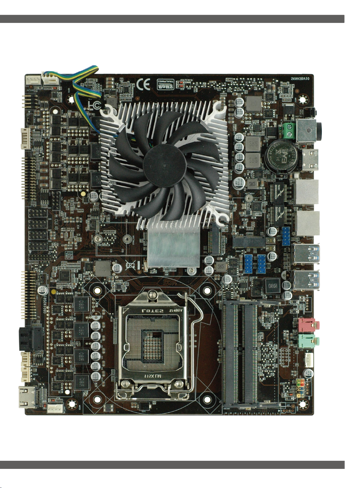
ZA-SK1050 2L4C Motherboard Diagram
Page 4

Motherboard Specification
Size
CPU
Graphics
Chipset
Memory
Internal I/O
Rear I/O
235mm x 197.5mm
Support Intel 6th/7th Core i7 i5 i3 Processor
NVIDIA GTX1050Ti
B150
2*DDR4 2133MHZ,Up to 32GB
4*USB2.0 Pin 7*USB Port
1* CPU Fan And GPU Fan
1*SYS Fan
2*LVDS Pin(support dual Channel 10 Bit)
4*SATA
4*COM
1*Front panel Pin
1*Audio Pin Port (2W/CH)
1* DC Power Input (19V)
1*HDMI
1*LAN
2*SATA
2*JSATA
4*USB3.0
1* Mic-in/Line-out
R
BIOS AMI
MINI_PCIE
SATA
LAN
Audio
Operating System
H/W Monitoring
Humidity
Temp
AMIBIOS,64M bit Flash Memory
1*Support Msata
1*Support WiFi
4*SATA
2*Realtek 8111E,10/100/1000
ALC662 Dual Channel Output
Windows7
Windows8
Windows10
Linux
Walk in LAN
System Power Management
Temperature Management
Voltage Management
0% ~ 95% (Relative Humidity,No Condensation)
-10°C ~ 55°C
Page 5

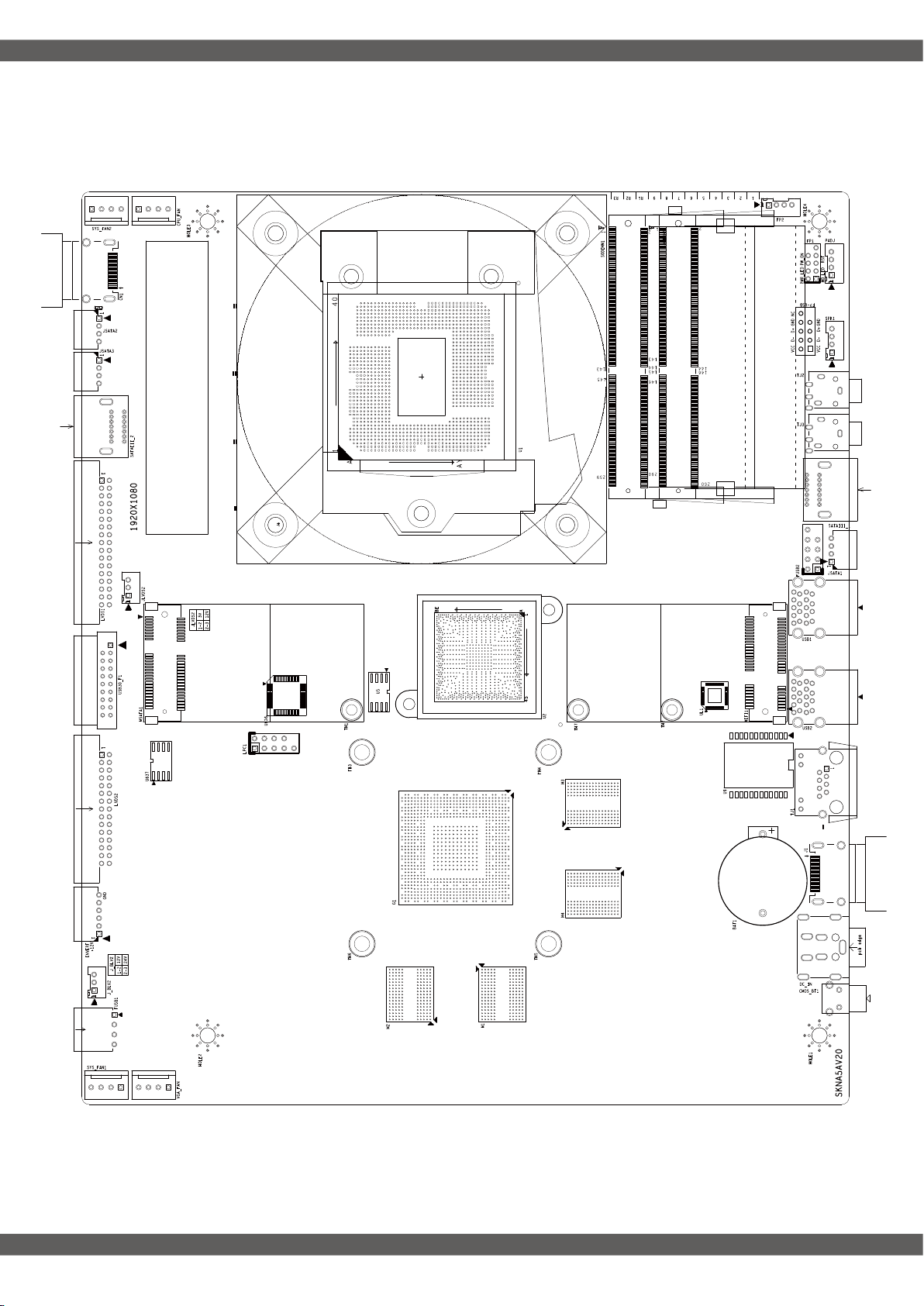
Motherboard I/O Interface Diagram
SYS_FAN1
VGA_FAN2
FUSB1
INVTER1
LVDS2
COM1-4
DP1
LVDS1
JSATA1-2
SATAIII_2
CN1
CPU_FAN
M2SATA
CMOS_BT1 19VDC HDMI TJ1 TJ4 USB3.0 USB3.0 Mic/Lineout
M2WIFI
FUSB3
FUSB4
FUSB2
SODIMM1
SODIMM2
FP1SPK1
Page 6

CPU_FUN
GPU_FAN2
SYS_FAN1
Note: these fan connectors are not jumpers, and the jumper cap is placed above the head.
Installation memory:
1. Please turn off the power before installing or removing the
memory, and dial down the AC power cord.
2. Carefully hold both ends of the memory stick, and do not touch
the metal contact above.
3. Align the gold fingers of the memory stick with the memory stick
slot, and pay attention to the convex point of the gold finger socket
to the upper slot in the direction;
4. Insert the memory stick 30 degrees into the memory slot, and
then press the memory stick down to the sound of "click"
The memory has been installed successfully and can be used
(note: press down the memory bar to avoid damaging the memory
too much)
DDR4
LVDS2
Memory installation diagram (for reference only) :
Note: static electricity damages electronic components of a computer or memory,
so before following these steps,Be sure to touch the grounded metal objects briefly
to remove static electricity from your body.
1 2 3
PIN 1-2 Close: PIN 2-3 Close:
3V 5V
接脚 接脚定义 接脚 接脚定义
1
3
5
LVDSA_DATA0N
7
LVDSA_DATA1N
9
LVDSA_DATA2N
11
13 GND 14 GND
15 LVDSA_CLKN
LVDSA_DATA3N
17
LVDSB_TX0N
19
LVDSB_TX1N
21
LVDSB_TX2N
23
25
27 LVDSB_CLKN 28 LVDSB_CLKP
29 LVDSB_TX3N 30 LVDSB_TX3P
或
LCDVDD
LCDVDD
GND
GND
1 2 3
2 LCDVDD
4
6
8 LVDSA_DATA0P
10 LVDSA_DATA1P
12 LVDSA_DATA2P
16
18
20 LVDSB_TX0P
22 LVDSB_TX1P
24
26 GND
GND
GND
LVDSA_CLKP
LVDSA_DATA3P
LVDSB_TX2P
(LVDS显示屏电路板供电选项)
Page 7

SATAIII_1
SATAIII_2
JSATA2
JSATA3
LPC
+5V 2. GND 3.GND 4.+12V
Note: this port belongs to the debugging port of the main board and cannot be used for other ports.
SPK1
FUSB1
FUSB2-4
Pin
1
3
Pin
1
2 DATA 0-
3 DATA 0+
4 GND
Define
SPKOUT_L-
F_USB1 F_USB2-4
Define
VCC
Pin
2
4 SPKOUT_R+SPKOUT_R-
Pin Pin
Define Define
VCC
1
DATA 0-
3
DATA0+
5
7
NC(CUT) GND
9
GND
2
4
6
8
10
Define
SPKOUT_L+
VCC
DATA1-
DATA1+
GND
INVERT
Pin Define Pin Define
1
3 ON/OFF 4 ADJ
5
GND
12V
2
6
GND
12V
Page 8

Pin Define Pin Define
FP1
Mic-in/Line-out
1
3
5
7
9
HDD LED+ PWR LED+
HDD LED- GND
GND
RESET_GND
GND
2
4
6
8
P_SWIN
GND
HDD Actiuve LED:1,3 Power Button:6,8
Power LED:2,4 Reset Button:5,7
*Other Matters Please consult the sales.
ShenZhen Zeal-All Technology Co.,Ltd
www.zeal-all.com
+86-0755-86959086
 Loading...