

Page 1

Exhibit T: User Manual 4400
FCC ID: EJM-X400
Page 2

User’s Guide
®
AnyPoint
DSL Gateway 4400
Share
Broadband
with
all your PCs
Page 3

Copyright
The Intel® Anypoint® DSL Gateway 4400 User’s Guide as well as the
software described in it, is furnished under license and may only be used or
copied in accordance with the terms of the license. The information in this
document is furnished for informational use only, is subject to change without
notice, and should not be construed as a commitment by Intel Corporation.
Intel Corporation assumes no responsibility or liability for any errors or
inaccuracies that may appear in this document or any software that may be
provided in association with this document.
Except as permitted by such license, no part of this document may be
reproduced, stored in a retrieval system, or transmitted in any form or by any
means without the express written consent of Intel Corporation.
Information in this document is provided in connection with Intel products. No
license, express or implied, by estoppel or otherwise, to any intellectual
property rights is granted by this document. Except as provided in Intel's
Terms and Conditions of Sale for such products, Intel assumes no liability
whatsoever, and Intel disclaims any express or implied warranty, relating to
sale and/or use of Intel products including liability or warranties relating to
fitness for a particular purpose, merchantability, or infringement of any patent,
copyright or other intellectual property right. Intel products are not intended for
use in medical, life saving, or life sustaining applications.
Intel may make changes to specifications and product descriptions at any
time, without notice.
Intel, AnyPoint, and Pentium are trademarks or registered trademarks of Intel
Corporation or its subsidiaries in the United States and other countries.
**Other names and brands may be claimed as the property of others.
Copyright (C) 2002, Intel Corporation. All rights reserved.
Intel Corporation, 5200 NE Elam Young Parkway, Hillsboro, OR 97214-6497
Page 4

Contents
Introduction .......................................................................1
Overview ............................................................................................................................2
Intel AnyPoint DSL Gateway 4400 Features .....................................................................3
System Requirements .........................................................................................................3
Service Requirements .........................................................................................................4
A look at the Gateway Hardware .......................................................................................5
Items included with the Gateway .......................................................................................8
Finding Information ...........................................................................................................9
Running the Internet Setup Wizard ....................................................................................9
Configuring your DSL Settings .........................................13
Specifying connection information ..................................................................................14
Specifying a connection type ...........................................................................................16
Specifying a PPP username and password .......................................................................19
Specifying an IP address ..................................................................................................22
Specifying a name server .................................................................................................25
Setting up the Gateway with a Network .......................... 29
Connecting the gateway to an Ethernet hub or switch .....................................................30
Connecting the gateway to a wireless network ................................................................32
Using the Wireless Network Configuration Wizard ........................................................35
Specifying a wireless network name (SSID) ....................................................................37
Correcting for wireless interference .................................................................................39
Changing or disabling encryption settings .......................................................................42
Specifying a wireless encryption key from text ...............................................................44
Entering a key manually ...................................................................................................46
Disabling wireless encryption ..........................................................................................49
Configuring the gateway’s firewall ..................................................................................51
Specifying the firewall security level ...............................................................................53
Specifying intrusion detection settings ............................................................................55
Specifying IP addresses to be excluded from being blocked ...........................................57
Using port forwarding ......................................................................................................59
Enabling port forwarding .................................................................................................61
Selecting a target computer by name ...............................................................................63
Selecting a target computer by IP address .......................................................................65
Creating a custom rule ......................................................................................................67
iii
Page 5

Using Advanced Configuration Options ........................... 71
Accessing advanced configuration options ......................................................................72
Changing the gateway password ......................................................................................74
Specifying wireless security settings ................................................................................76
Resetting the gateway or reloading default settings .........................................................79
Exposing a computer outside the firewall ........................................................................81
Enabling remote access ....................................................................................................83
Specifying the Host and Domain names ..........................................................................85
Specifying LAN and DHCP settings ................................................................................87
Disabling Universal Plug and Play (UPnP) .....................................................................90
Diagnostics and Troubleshooting .................................... 93
Getting network status information ..................................................................................94
Getting status details ......................................................................................................100
Running Diagnostics ......................................................................................................107
Problems and solutions ..................................................................................................108
If all else fails .................................................................................................................120
Reading the gateway indicator lights .............................................................................120
Reading settings and device status .................................................................................120
Glossary ........................................................................123
Glossary ..........................................................................................................................124
Regulatory Compliance Statements ............................... 131
Safety compliance statements ........................................................................................132
Emissions compliance statements ..................................................................................132
RF exposure compliance statements ..............................................................................133
Telecom compliance statements .....................................................................................133
Canadian compliance statements ...................................................................................135
European Union compliance statements ........................................................................136
Product Ecology Statements ..........................................................................................137
iv
Page 6

Chapter 1
Introduction
This chapter provides a basic overview of the gateway’s
features, list its system and service requirements, lists
the items included with gateway product package,
explains where to find more information, and explains
how to start the Internet Setup Wizard.
■ Intel AnyPoint DSL Gateway 4400 Features
■ System Requirements
■ Service Requirements
■ A look at the Gateway Hardware
■ Items included with the Gateway
■ Finding Information
■ Running the Internet Setup Wizard
Copyright © 2002 Intel Corporation
1
Page 7
Overview
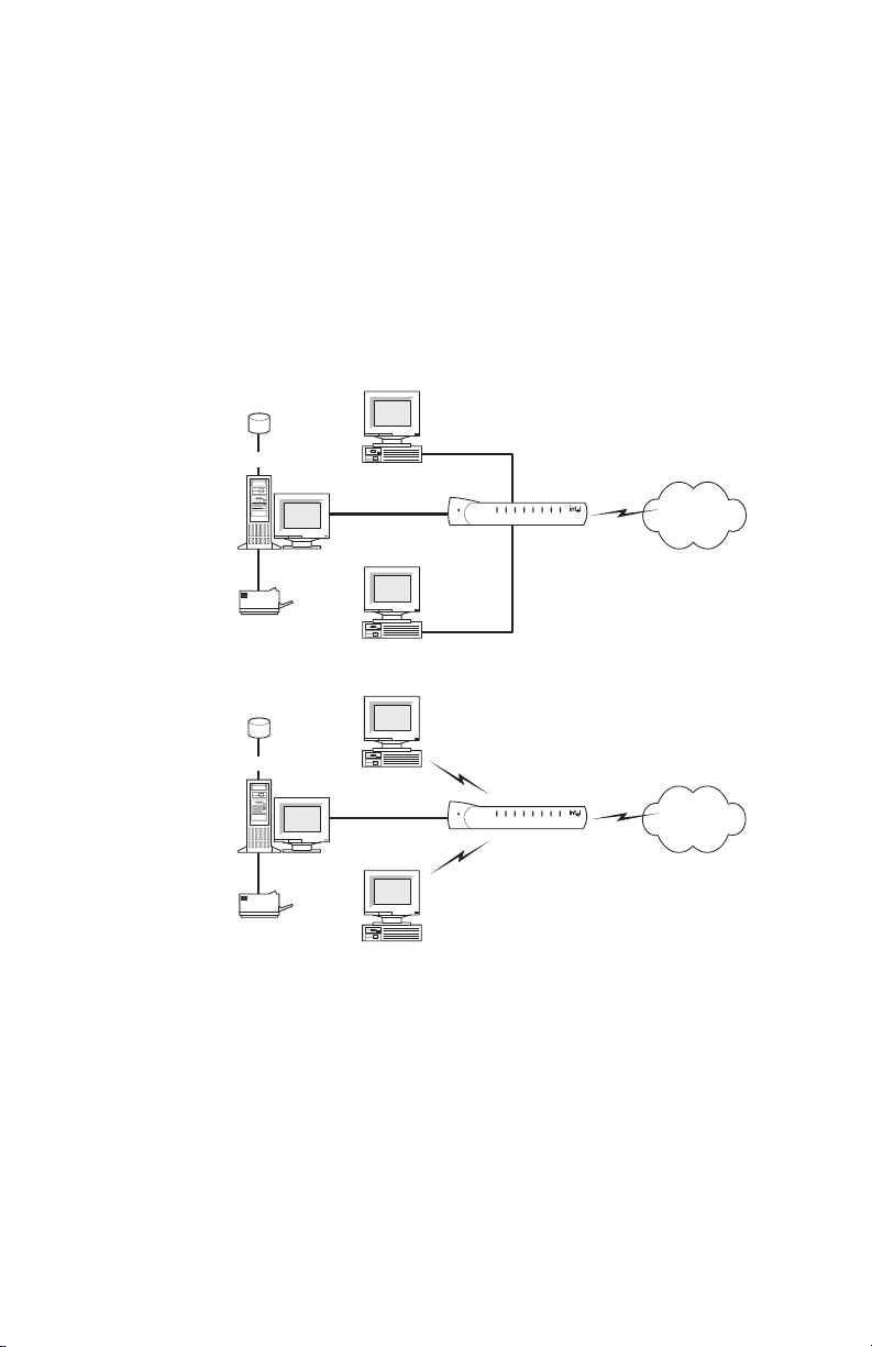
The Intel® AnyPoint® DSL Gateway 4400 is an advanced
services gateway that combines the functions of a Bridge,
Router, Switch, and DSL Modem in a single box for Internet
access and computer connectivity.
Using the gateway, you can share Internet access
seamlessly among all the computers on your network
whether you are using Ethernet or 802.11b Wireless adapters
or a combination of any of these technologies.
Data
Shared Drive
Server
Laser Printer
Data
Shared Drive
Server
Laser Printer
The Intel
AnyPoint DSL Gateway 4400 connects directly to a
PC
Internet
Gateway
PC
PC
Internet
Gateway
PC
DSL (Digital Subscriber Line) using the built-in DSL modem.
Using the gateway and its built-in DSL modem together
enables powerful Internet access on a home or smallbusiness network.
2
Page 8

Intel AnyPoint DSL Gateway 4400 Features
The gateway has the following features:
• Easy to install
• Automatic first time use setup wizard
• Port forwarding
• Configurable WAN MAC Address
• UPnP support
• Automatic diagnostic tests
• Readily available troubleshooting tips
• Simple Web-based user interface
• Internet sharing on your network
• Built-in firewall for network security
System Requirements
To configure the gateway, your computer must meet
certain requirements. Choose the list appropriate to your
computer’s operating system:
Chapter 1 – Introduction
Windows* • 166 MHz Pentium
better
• Windows* 95, 98, Me, 2000, XP, or NT*
• 32 MB of RAM, or more
• CD-ROM drive
• 800 x 600 resolution monitor (SVGA) or higher
• One of the following:
• 10/100 Ethernet or 10 baseT Ethernet adapter
• Wireless PC Card (802.11b/Wi-Fi)
• Web browser (Microsoft Internet Explorer* 5.0 or
later, Netscape Navigator* 4.75 or later, or
equivalent)
Copyright
©
2002 Intel Corporation
processor, performance level or
3
Page 9

Chapter 1 – Introduction
Macintosh* • PowerPC* or 680x0*
• Mac OS 7.6.1 or later
• 32 MB of RAM, or more
• 800 x 600 resolution monitor (SVGA) or higher
• One of the following:
• 10/100 Ethernet or 10 baseT Ethernet adapter
• Wireless PC Card (802.11b/Wi-Fi)
• CD-ROM drive
• Web browser (Microsoft Internet Explorer 5.0 or later;
Netscape Navigator 4.75 or later, or equivalent)
Linux • 166 MHz Pentium processor or higher
• 32MB of RAM, or more
• 800 x 600 resolution monitor (SVGA) or higher
• One of the following:
• 10/100 Ethernet or 10 baseT Ethernet adapter
• Wireless PC Card (802.11b/Wi-Fi)
• CD-ROM drive
• X-Windows* system
• Graphical Web browser (Netscape Navigator 4.75 or
later)
Service Requirements
Before you can use the gateway, you must have the
following services activated:
• Broadband account from your local telephone
company or Broadband provider
• Broadband Internet access account from your local
Broadband provider or Internet Service Provider
(ISP)
If you do not have these services set up, then contact
your local telephone company for more information.
4
Copyright
©
2002 Intel Corporation
Page 10

Chapter 1 – Introduction
A look at the Gateway Hardware
Front Panel The Intel Gateway’s front panel has a series of eight
lights (plus a power on indicator) that provide information
about the gateway’s operational status.
Power
123
WirelessSecurityInternetSystem
4
Ethernet
AnyPoint® Gateway
Power Normally this light is on. If it is not on, check
that the power cable connectors are securely in
place.
System Green blinking - The gateway is operating
correctly.
Yellow blinking - The gateway is operating
correctly but has detected another DHCP
server connected to one of the four Ethernet
connectors. Disconnect each Ethernet cable,
one at a time, until the system returns to green
blinking. Change the PC you've identified as a
DHCP server to a DHCP client. (See the
Troubleshooting chapter for instructions.)
If this LED is not blinking, the system is not
operating correctly. See Chapter 5 for
troubleshooting information.
Copyright
©
2002 Intel Corporation
5
Page 11

Chapter 1 – Introduction
Internet Off - the DSL driver is not loaded.
Green blinking - the gateway is trying to
connect to the Internet.
Green solid - the gateway is connected to your
ISP but no traffic is being passed.
Amber blinking - the gateway is connected to
your ISP and traffic is being passed. This LED
blinks at a rate that corresponds to the amount
of Internet traffic (slow with little traffic and
increasingly faster as Internet traffic increases).
Security Green solid - The Firewall Settings Security
Level is set to: Normal, High, or Very High.
Red solid - The Firewall Settings Security Level
is set to: Enable Troubleshooting Mode (via the
Firewall Settings Advanced button).
Yellow blinking - A user, that is not allowed
access to your wireless network (via Advanced
> Wireless Security), is attempting to connect
to the gateway.
6
Copyright
©
2002 Intel Corporation
Page 12

Chapter 1 – Introduction
Wireless Off - There are no wireless devices
communicating with the gateway.
Green solid - at least one wireless device is
connected to the gateway.
Green blinking - traffic is being passed
between at least one wireless device and the
gateway.
Ethernet
1-4
Off - no PC is connected to any of the four
Ethernet ports.
Green solid - A valid link has been established
at 10Mbps.
Green blinking - traffic is being passed at
10Mbps.
Yellow solid - A valid link has been established
at 100Mbps.
Yellow blinking - traffic is being passed at
100Mbps.
Back panel
connectors
Copyright
The Intel Gateway’s back panel includes the cable
connectors and Reset button.
Power Accepts the cylinder end of the power cable.
Ethernet Accept RJ-45 Ethernet-style connectors for
©
2002 Intel Corporation
4321
12V/1.2A
Power
Ethernet
Reset
Plug the other end of the power cable into a
standard electrical outlet. (It is recommended
that you use a surge protector.) See the Power
light on the front panel in the previous section.
connecting up to four PCs to the gateway’s 4port switch.
DSL
7
Page 13

Chapter 1 – Introduction
Reset Use a blunt object, such as a paper clip, to
press the reset switch. You can use the reset
switch to either:
• Reset the gateway without losing its current
setup values. Press, then immediately release
the reset switch.
• Reset the gateway to its factory-default values.
Press the reset switch and hold it in the pressed
state for at least 5 seconds before releasing it.
DSL Accepts a standard phone cable connector for
attaching the gateway to your DSL (digital
subscriber line) service outlet.
Items included with the Gateway
You should have the following items ready prior to
installation:
•Intel
• Power Supply
• Standard phone cable
• Standard Ethernet Cable
•Intel
•Intel
AnyPoint DSL Gateway 4400
AnyPoint DSL Gateway 4400 CD-ROM
AnyPoint DSL Gateway 4400 Installation Guide
The Gateway
CD-ROM
8
The exact contents of the CD-ROM varies by Broadband
provider. Do not assume that the CDs are
interchangeable. One provider may have different default
software configurations than another, and the
configurations are often not compatible with each other.
Only use the CD supplied to you by your provider.
Copyright
©
2002 Intel Corporation
Page 14

All gateway CDs contain the following:
•A readme text file, with basic product information and
• The Intel
• The Intel
Finding Information
Chapter 1 – Introduction
any known issues that were not available at the time
of the publication of this manual
AnyPoint DSL Gateway 4400 Installation
Guide, available as a .pdf file
AnyPoint DSL Gateway 4400 User’s Guide,
available as a .pdf file
Installation
Guide
The Installation Guide offers an overview of the basic
steps necessary to connect and configure your new
gateway.
User’s Guide The User’s Guide contains more detailed information on
connecting and configuring your new gateway. It is
designed for users who have less experience with
installing and configuring gateways and home networking
equipment. The User’s Guide can also be used as a
helpful reference tool.
Online Help Use the online help for more information on screen
descriptions. Troubleshooting information is also
available for the diagnostic tests.
Running the Internet Setup Wizard
Note The following describes how to access the
Internet Setup Wizard for purposes of modifying
the gateway’s configuration. If the gateway has
not yet been configured, then follow the
instructions provided in the Installation Guide.
Copyright
©
2002 Intel Corporation
9
Page 15
Chapter 1 – Introduction
To run the Internet Setup Wizard:
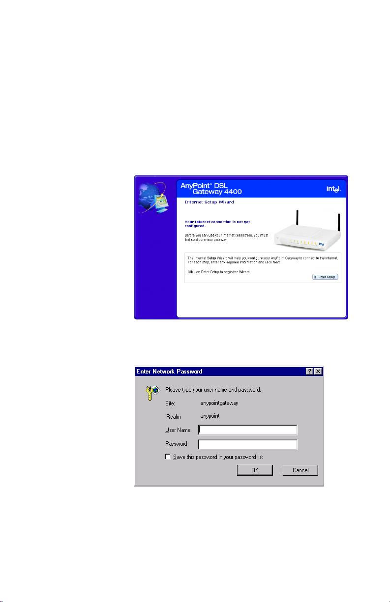
1 Insert the CD and wait for the Internet Setup Wizard
window to appear. (If the Autorun window does not
appear, run the program autorun.exe on the CD.)
The following screen will appear, if the gateway has
not yet been configured. If the gateway has already
been configured, a slightly different screen will
appear.
10
2 Click the Enter Setup button.
The following appears.
3 Enter admin in both the User Name and Password
fields, and then click OK.
Copyright
©
2002 Intel Corporation
Page 16

Chapter 1 – Introduction
If the gateway has not yet been configured, you will be
required to enter specific information before you can
access other features of the Setup Wizard. If the gateway
has already been configured, you can access other
features of the Internet Setup Wizard using the available
menu selections. Each feature is described in this User
Guide.
Copyright
©
2002 Intel Corporation
11
Page 17

Chapter 1 – Introduction
12
Copyright
©
2002 Intel Corporation
Page 18

Chapter 2
Configuring your DSL Settings
The Installation Guide provides step-by-step instructions
for setting up and configuring a single wired or wireless
PC connected to the gateway.
During installation, you have the option of letting setup
automatically detect your settings or setting these
manually.
If you accept the default selection, allowing the gateway
to automatically detect your settings, then you should
only need to enter minimal information, if any at all.
If you elect to set your settings manually, then you will
have to step through several screens to complete the
setup.
This chapter covers all the possible settings you may
have to enter in the following topics:
■ Specifying connection information
■ Specifying a connection type
■ Specifying a PPP username and password
■ Specifying an IP address
■ Specifying a name server
Copyright © 2002 Intel Corporation
13
Page 19
Chapter 2 – Configuring your DSL Settings
Specifying connection information
You specify VPI/VCI connection information using the
Connection Information screen.
Related topics •See Specifying a connection type on page 16.
•See Specifying a PPP username and password on
page 19.
•See Specifying an IP address on page 22.
•See Specifying a name server on page 25.
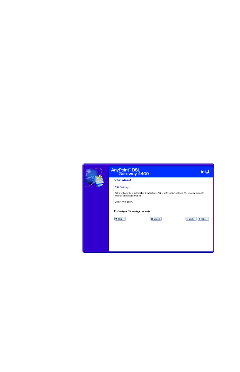
Step-by-step To specify your VPI/VCI connection information:
1 Click the Settings menu to expand its selections.
2 Click Next.
The following appears.
14
Copyright
©
2002 Intel Corporation
Page 20

Chapter 2 – Configuring your DSL Settings
3 Click Configure DSL settings manually then click
Next.
The following appears.
4 Enter the VPI information in the VPI field.
5 Enter the VCI information in the VCI field.
6 Click Next.
More about VPI
Copyright
©
2002 Intel Corporation
Virtual Path Identifier. This is part of the PVC. This,
combined with the VCI, establishes your “channel”
through the phone company equipment. Acceptable
values are: 0-255.
VCI
Virtual Circuit Identifier. This number is part of the PVC. It
establishes your “channel” through the telephone
company equipment. Acceptable values are: 0-65,535.
15
Page 21

Chapter 2 – Configuring your DSL Settings
Specifying a connection type
You specify a connection type using the Specify
Connection Type screen.
Related topics •See Specifying connection information on page 14.
•See Specifying a PPP username and password on
page 19.
•See Specifying an IP address on page 22.
•See Specifying a name server on page 25.
Step-by-step To specify a connection type:
1 Click the Settings menu to expand its selections.
2 Click Next.
The following appears.
16
Copyright
©
2002 Intel Corporation
Page 22

Chapter 2 – Configuring your DSL Settings
3 Click Configure DSL settings manually then click
Next until you see the following screen.
4 Select one of the following connection types, as
required by your ISP, then click Next. (See More
about for more information.)
• Point-to-Point over ATM (PPPoA)
• Point-to-Point over Ethernet (PPPoE)
• RFC 1483 Bridged Ethernet option
More about PPPoA
Copyright
©
2002 Intel Corporation
Point-to-Point over ATM Protocol is a protocol that some
ISPs use to give users access to the ISP’s computers
and the Internet. Your ISP can tell you if you need
PPPoA, or a different protocol supported by your
gateway (Bridged Ethernet, or Point-to-Point Protocol
over Ethernet (PPPoE).
PPPoE
Point-to-Point over Ethernet Protocol is a protocol that
some ISPs use to give users access to the ISP’s
computers and the Internet. Your ISP can tell you if you
need PPPoE, or a different protocol supported by your
17
Page 23

Chapter 2 – Configuring your DSL Settings
gateway (Bridged Ethernet, or Point-to-Point over ATM
Protocol (PPPoA).
RFC1483
A standard that provides guidelines for Bridged Ethernet
and Routed Ethernet connection protocols. Your ISP can
tell you if you will use one of the RFC1483 protocols, or a
different protocol supported by your gateway (PPPoA,
PPPoE).
18
Copyright
©
2002 Intel Corporation
Page 24

Chapter 2 – Configuring your DSL Settings
Specifying a PPP username and password
You specify a PPP username and password using the
PPP Username/Password screen.
Related topics •See Specifying connection information on page 14.
•See Specifying a connection type on page 16.
•See Specifying an IP address on page 22.
•See Specifying a name server on page 25.
Step-by-step To specify a PPP username and password:
1 Click the Settings menu to expand its selections.
2 Click Next.
The following appears.
Copyright
©
2002 Intel Corporation
19
Page 25

Chapter 2 – Configuring your DSL Settings
3 Click Configure DSL settings manually then click
Next until you see the following screen.
4 On the “Connection Type” screen, click either Point-
to-Point over ATM (PPPoA) or Point-to-Point over
Ethernet (PPPoE).
5 Click Next .
The following appears.
20
6 Enter a PPP username and password in the User
Name and Password fields provided.
Important! Your username and password are case
sensitive.
Copyright
©
2002 Intel Corporation
Page 26

Chapter 2 – Configuring your DSL Settings
Copyright
©
2002 Intel Corporation
21
Page 27

Chapter 2 – Configuring your DSL Settings
Specifying an IP address
You specify an IP address using the Specify IP Address
screen.
Related topics •See Specifying connection information on page 14.
•See Specifying a connection type on page 16.
•See Specifying a PPP username and password on
page 19.
•See Specifying a name server on page 25.
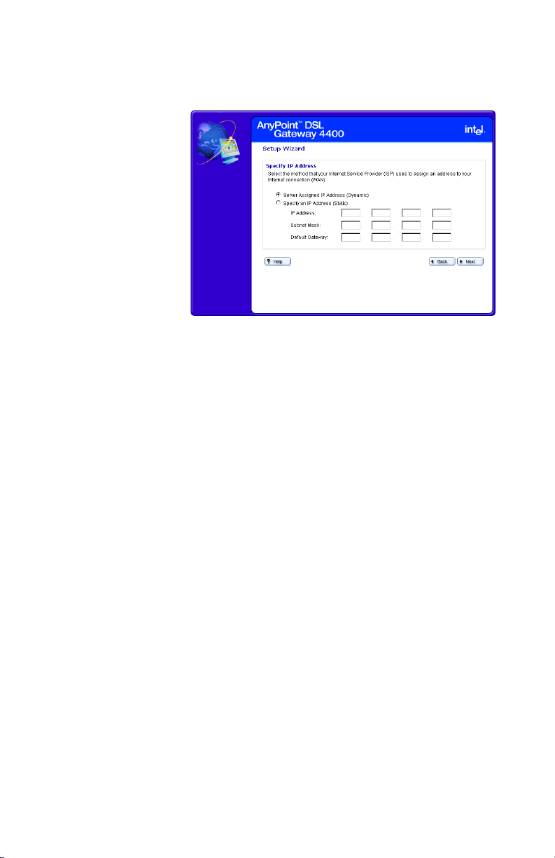
Step-by-step To specify an IP address:
1 Click the Settings menu to expand its selections.
2 Click Next.
The following appears.
22
Copyright
©
2002 Intel Corporation
Page 28
Chapter 2 – Configuring your DSL Settings
3 Click Configure DSL settings manually then click
Next until you see the following screen.
4 Select one of the following methods your ISP uses to
assign an address to your Internet connection.
• Server assigned IP address (dynamic) –
Select this option if your ISP assigns addresses
dynamically.
• Specify an IP address (static) – Select this
option if your ISP assigns addresses statically. If
you select this option then you must enter the IP
Address, Subnet Mask, and Default Gateway
information in the fields provided.
More about Each computer or networked device on the Internet is
identified by a unique IP address. Your gateway must be
identified by the correct address in order for you to
access the Internet.
Your ISP uses one of two methods to assign an IP
address to you:
• Dynamic (also called server-assigned, automatic, or
DHCP). If your ISP assigns IP addresses
dynamically, your gateway receives an IP address
from a pool of IP addresses when you connect to
Copyright
©
2002 Intel Corporation
23
Page 29

Chapter 2 – Configuring your DSL Settings
your ISP. Your ISP “owns” the IP addresses in the
pool.
• Static (also called permanent). If your ISP assigns
static IP addresses, your provider selects an address
from an assigned pool and assigns it to you
permanently. This number is provided on the setup
information page given to you by your ISP.
24
Copyright
©
2002 Intel Corporation
Page 30

Chapter 2 – Configuring your DSL Settings
Specifying a name server
You specify a name server using the Specify a Name
Server screen.
Related topics •See Specifying connection information on page 14.
•See Specifying a connection type on page 16.
•See Specifying a PPP username and password on
page 19.
•See Specifying an IP address on page 22.
Step-by-step To specify a name server:
1 Click the Settings menu to expand its selections.
2 Click Next.
The following appears.
Copyright
©
2002 Intel Corporation
25
Page 31

Chapter 2 – Configuring your DSL Settings
3 Click Configure DSL settings manually then click
Next until you see the following screen.
4 Select the Specify an IP Address (Static) option,
enter the IP Address, Subnet Mask, and Default
Gateway information in the fields provided, then click
Next.
The following appears.
5 Enter the Primary DNS (and optionally, secondary) IP
provided by your ISP.
More about A name server DNS IP address is the IP address of the
computer that your ISP uses to translate between
numeric IP addresses and human-readable addresses.
26
Copyright
©
2002 Intel Corporation
Page 32

Chapter 2 – Configuring your DSL Settings
For example, 192.168.0.254 is a numeric IP address and
www.intel.com is a human-readable address.
Copyright
©
2002 Intel Corporation
27
Page 33

Chapter 2 – Configuring your DSL Settings
28
Copyright
©
2002 Intel Corporation
Page 34

Chapter 3
Setting up the Gateway with a Network
This chapter explains how to connect additional
computers to your wired or wireless network.
Note Do not attempt to connect multiple computers to
form a network until you have configured the
gateway to work with a single computer, as
described in the Installation Guide.
■ Connecting the gateway to an Ethernet hub or switch
■ Connecting the gateway to a wireless network
■ Using the Wireless Network Configuration Wizard
■ Configuring the gateway’s firewall
■ Using port forwarding
Copyright © 2002 Intel Corporation
29
Page 35

Chapter 3 – Setting up the Gateway with a Network
Connecting the gateway to an Ethernet hub or switch
Once you have established a connection between the
gateway and a single computer with an Ethernet adapter,
you can then connect additional computers to the wired
network.
Note Do not attempt to connect multiple computers to
form a network until you have configured the
gateway to work with a single computer. Refer to
your Installation Guide for instructions on
configuring the gateway to do this.
Related topics •See Connecting the gateway to a wireless network
on page 32.
•See Using the Wireless Network Configuration
Wizard on page 35.
•See Configuring the gateway’s firewall on page 51.
•See Using port forwarding on page 59.
30
Copyright
©
2002 Intel Corporation
Page 36

Chapter 3 – Setting up the Gateway with a Network
Step-by-step To connect the gateway to a hub or switch:
1 Connect one end of the Ethernet cable (included with
the gateway) to any one of the four Ethernet ports on
the gateway.
2 Connect the other end to the Ethernet cable to an
available port on your hub or switch.
1
2
V
/1
.2
A
Power
Eth
ernet
R
e
set
DSL
Copyright
3 Connect the power cable to the power supply.
4 Connect the power cable to an electrical wall outlet.
5 Connect the power supply cable to the Power port on
Note If you are using the gateway as a DHCP server,
©
2002 Intel Corporation
the gateway.
make sure the computers on your network are
configured to be DHCP clients. Refer to Chapter
5 for information.
31
Page 37

Chapter 3 – Setting up the Gateway with a Network
Connecting the gateway to a wireless network
Once you have established a connection between the
gateway and a single computer with an 802.11b wireless
adapter, you can then connect additional computers to
the wireless network.
Note Do not attempt to connect multiple computers to
form a network until you have configured the
gateway to work with a single computer. Refer to
your Installation Guide for instructions on
configuring the gateway to do this.
Related topics •See Connecting the gateway to an Ethernet hub or
switch on page 30.
•See Using the Wireless Network Configuration
Wizard on page 35.
•See Configuring the gateway’s firewall on page 51.
•See Using port forwarding on page 59.
Step-by-step To connect the gateway to a wireless network:
®
• refer to the Intel
AnyPoint® Wireless II Installation
Guide for instructions on installing the remaining
computers with wireless adapters on your network. (If
you have purchased a non-Intel 802.11b wireless
adapter, refer to the instructions provided with your
adapter.)
• Set the Network Name (SSID) and Encryption to be
the same for the gateway and each wireless adapter.
To set the Network Name and Encryption for your
wireless adapters, refer to the instructions provided
with them.
To set the Network Name and Encryption for the
gateway:
1 Click the Settings menu to expand its selections.
32
Copyright
©
2002 Intel Corporation
Page 38

Chapter 3 – Setting up the Gateway with a Network
2 Click Wireless to view your current wireless settings.
The following appears.
3 Click the Wireless Setup button to enter the
Wireless Setup Wizard.
The following appears.
Copyright
4 Click Next, then enter the Network Name.
©
2002 Intel Corporation
33
Page 39

Chapter 3 – Setting up the Gateway with a Network
5 Click Next, then select an encryption option.
Each of these steps is described in more detail on
subsequent pages.
Note If you change the Network Name (SSID) or the
Encryption Password and forget the values, you
must reset the gateway to the factory default
settings. The reset button is located on the back
of the gateway and is not labeled. This button is
recessed. Use a paper clip to depress the button
for at least 5 seconds. You may then reconfigure
the gateway with the settings given to you by
your ISP, and the 802.11b wireless adapters
with the default gateway settings.
34
Copyright
©
2002 Intel Corporation
Page 40

Chapter 3 – Setting up the Gateway with a Network
Using the Wireless Network Configuration Wizard
The Wireless Network Wizard guides you through the
steps necessary to configure a wireless network with
your Gateway.
Related topics •See Specifying a wireless network name (SSID) on
page 37.
•See Correcting for wireless interference on page 39.
•See Changing or disabling encryption settings on
page 42.
•See Specifying a wireless encryption key from text on
page 44.
•See Entering a key manually on page 46.
•See Disabling wireless encryption on page 49.
Step-by-step To use the Wireless Wizard:
1 Click the Settings menu to expand its selections.
2 Click Wireless to view your current wireless settings,
then click the Wireless Setup button to enter the
Wireless Setup Wizard.
The following appears.
Copyright
3 For each step, enter any required information then
©
2002 Intel Corporation
click Next.
35
Page 41

Chapter 3 – Setting up the Gateway with a Network
4 Click Help on any screen for more information.
5 Click Back on any screen to move back to the
previous window.
6 Click Next on any screen to move forward to the next
window.
7 Click Cancel on any screen to exit the Wireless
Wizard, without applying changes.
More about To communicate with each other, all wireless devices on
the same network must use the same Network Name
(SSID) and Encryption Password (if encryption is
enabled). In the next several screens you will enter the
Network Name and specify encryption.
36
Copyright
©
2002 Intel Corporation
Page 42

Chapter 3 – Setting up the Gateway with a Network
Specifying a wireless network name (SSID)
You specify a network name (SSID) using the Wireless
Settings – Network Name screen.
Related topics •See Correcting for wireless interference on page 39.
•See Changing or disabling encryption settings on
page 42.
•See Specifying a wireless encryption key from text on
page 44.
•See Entering a key manually on page 46.
•See Disabling wireless encryption on page 49.
Step-by-step To specify a network name (SSID):
1 Click the Settings menu to expand its selections.
2 Click Wireless to view your current wireless settings,
then click the Wireless Setup button to enter the
Wireless Setup Wizard.
3 Click Next until you see the “Network Name” screen.
The following appears.
Copyright
4 Enter a string of up to 32 letters or numbers (case
©
2002 Intel Corporation
sensitive) in the Network Name (SSID) field. (See
37
Page 43

Chapter 3 – Setting up the Gateway with a Network
“Default Network Name,” below, for more
information.)
5 Click Next.
Default
Network Name
The factory default value for the Network Name, unique
for each gateway, is located on the bottom of the
gateway and is originally displayed in the Network Name
(SSID) field. You may want to change this value from the
default setting to something you can easily remember.
More about To communicate with each other, all wireless devices on
the same network must use the same Network Name
(SSID) and Encryption Password (if encryption is
enabled). In this screen you enter the Network Name. On
a subsequent screen you will specify an Encryption
Password.
Note Network Name is also referred to as SSID,
ESSID, BSSID, or network code.
38
Copyright
©
2002 Intel Corporation
Page 44

Chapter 3 – Setting up the Gateway with a Network
Correcting for wireless interference
If you are experiencing wireless interference you can
correct for it using the Advanced Wireless Settings,
accessible from the Wireless Settings – Network Name
screen.
Related topics •See Specifying a wireless network name (SSID) on
page 37.
•See Changing or disabling encryption settings on
page 42.
•See Specifying a wireless encryption key from text on
page 44.
•See Entering a key manually on page 46.
•See Disabling wireless encryption on page 49.
Step-by-step To correct for interference with your wireless connection:
1 Click the Settings menu to expand its selections.
2 Click Wireless to view your current wireless settings,
then click the Wireless Setup button to enter the
Wireless Setup Wizard.
3 Click Next until you see the “Network Name” screen.
Copyright
©
2002 Intel Corporation
39
Page 45

Chapter 3 – Setting up the Gateway with a Network
4 Click Advanced.
The following appears.
5 Select an alternate channel using the Channel list
box.
6 Select an alternate transfer rate using the Transfer
Rate box.
More about
Channel In areas where many networks are using the same
channel, throughput on all the networks may decline.
In addition, if there is interference on the channel,
signal quality is affected. If the performance of your
network declines, try selecting another channel. It is
recommended that you try channels 6 and 11 first as
alternative channels. The default channel is 6.
40
Copyright
©
2002 Intel Corporation
Page 46

Chapter 3 – Setting up the Gateway with a Network
Transfer Rate By default, the transfer rate between wireless
devices is automatically determined. Generally, you
will not need to change this value. However,
decreasing the transfer rate may enable you to
transmit across greater distances.
Header Length (Preamble) The Header length is the format for labeling the
information sent between devices. The only available
setting is Long. The short header length is not
supported because not all wireless devices support
this feature. You must set all your other wireless
devices, to which the gateway is connected, to Long
(typically the default setting).
Copyright
©
2002 Intel Corporation
41
Page 47

Chapter 3 – Setting up the Gateway with a Network
Changing or disabling encryption settings
In a Wireless Local Area Network (WLAN), you can use
encryption to implement security and protect your
information. The default encryption setting is 40/64-bit
hexadecimal. Network encryption does not provide
absolute protection for your data, but it does make it
more difficult for someone else to intercept that data. It is
recommended that you utilize the encryption feature of
this product.
Related topics •See Specifying a wireless network name (SSID) on
page 37.
•See Correcting for wireless interference on page 39.
•See Specifying a wireless encryption key from text on
page 44.
•See Entering a key manually on page 46.
•See Disabling wireless encryption on page 49.
Step-by-step To change or disable encryption:
42
1 Click the Settings menu to expand its selections.
2 Click Wireless to view your current wireless settings,
then click the Wireless Setup button to enter the
Wireless Setup Wizard.
Copyright
©
2002 Intel Corporation
Page 48

Chapter 3 – Setting up the Gateway with a Network
3 Click Next until you see the “Encryption” screen.
(Your encryption screen may contain different
information, depending on how encryption was last set.
See the following encryption topics for more information.
4 Select an encryption option then enter the required
information in the fields associated with that
selection. See the following topics for more
information.
More about The longer the encryption key is, the stronger the
encryption. The gateway uses either a 40(64)-bit key or a
104(128)-bit key. A 104(128)-bit key has several trillion
times more combinations than a 40(64)-bit key. For
added security, you should change your encryption key
often.
Important! The gateway and each adapter in the
network must have the same encryption
keys.
Copyright
©
2002 Intel Corporation
43
Page 49

Chapter 3 – Setting up the Gateway with a Network
Specifying a wireless encryption key from text
If you have all Intel® AnyPoint® adapters, you can create
an encryption key from a 5 or 13 character string. A 5
character string provides 40-bit encryption, while a 13
character string provides 104-bit encryption. The string
you enter must be exactly 5 or 13 characters.
Related topics •See Specifying a wireless network name (SSID) on
page 37.
•See Correcting for wireless interference on page 39.
•See Changing or disabling encryption settings on
page 42.
•See Entering a key manually on page 46.
•See Disabling wireless encryption on page 49.
Step-by-step To specify a wireless encryption key from text:
1 Click the Settings menu to expand its selections.
2 Click Wireless to view your current wireless settings,
then click the Wireless Setup button to enter the
Wireless Setup Wizard.
3 Click Next until you see the “Encryption” screen.
44
Copyright
©
2002 Intel Corporation
Page 50

Chapter 3 – Setting up the Gateway with a Network
4 Click the Generate a key from text option.
The following appears.
5 Enter a 5-character (40-bit) or a 13-character (104-
bit) string, in any combination of letters, numbers, or
special characters (case sensitive) in the Network
Encryption Key field.
Copyright
©
2002 Intel Corporation
45
Page 51

Chapter 3 – Setting up the Gateway with a Network
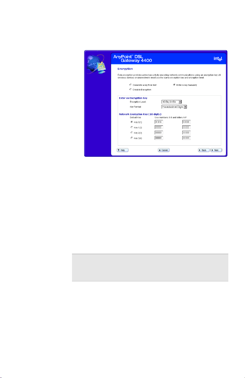
Entering a key manually
If you are not using Intel® AnyPoint® network adapters
you can manually enter a key, either as a series of 40/64
bit or 104/128-bit hexadecimal digits (characters 0
through 9 and A through E) or as 40/64 bit or 104/128-bit
ASCII characters (any character).
Related topics •See Specifying a wireless network name (SSID) on
page 37.
•See Correcting for wireless interference on page 39.
•See Changing or disabling encryption settings on
page 42.
•See Specifying a wireless encryption key from text on
page 44.
•See Disabling wireless encryption on page 49.
Step-by-step To enter a key manually:
1 Click the Settings menu to expand its selections.
2 Click Wireless to view your current wireless settings,
then click the Wireless Setup button to enter the
Wireless Setup Wizard.
3 Click Next until you see the “Encryption” screen.
46
Copyright
©
2002 Intel Corporation
Page 52
Chapter 3 – Setting up the Gateway with a Network
4 Click the Enter a key manually option.
Your screen will look similar to the following.
5 Select either Hexadecimal digits or ASCII
Characters from the Key Format list box.
6 Select either 40 Bit/64 Bit or 104 Bit/128 Bit from
the Encryption Level list box.
7 Click a Key option, then enter a unique 10
hexadecimal digit (2 pairs of 5-digits) string in its
associated field. The four Key options allow you to
specify four different keys that you can select at any
time.
Note You can only use one encryption key at a time.
Having four sets of keys allows you to quickly
change your encryption, if necessary.
More about A 40/64-bit key can consist of 10 hexadecimal digits or 5
ASCII characters:
• Example Hex Key: 1AC78 24DE5
• Example ASCII Key: JimBo
Copyright
©
2002 Intel Corporation
47
Page 53

Chapter 3 – Setting up the Gateway with a Network
A 104/128-bit key can consist of 26 hexadecimal digits or
13 ASCII characters.
• Example Hex Key: 10111 2EF14 1510 2453 6543
9991
• Example ASCII Key: IntelWireless
48
Copyright
©
2002 Intel Corporation
Page 54

Chapter 3 – Setting up the Gateway with a Network
Disabling wireless encryption
You can disable encryption if you are not worried about
security and want to slightly improve data transmission.
Related topics •See Specifying a wireless network name (SSID) on
page 37.
•See Correcting for wireless interference on page 39.
•See Changing or disabling encryption settings on
page 42.
•See Specifying a wireless encryption key from text on
page 44.
•See Entering a key manually on page 46.
Step-by-step To disable the encryption settings:
1 Click the Settings menu to expand its selections.
2 Click Wireless to view your current wireless settings,
then click the Wireless Setup button to enter the
Wireless Setup Wizard.
3 Click Next until you see the “Encryption” screen.
Copyright
©
2002 Intel Corporation
49
Page 55

Chapter 3 – Setting up the Gateway with a Network
4 Click the Disable Encryption option.
The following appears.
5 Click Next to apply the change.
Important! Be sure to also disable encryption for
each adapter in your wireless network.
Refer to the documentation for you
wireless adapter.
More about In a Wireless Local Area Network (WLAN), you can use
encryption to implement security and protect your
information. The default encryption setting is 40/64-bit
hexadecimal. Network encryption does not provide
absolute protection for your data, but it does make it
more difficult for someone else to intercept that data. It is
recommended that you utilize the encryption feature of
this product.
50
Copyright
©
2002 Intel Corporation
Page 56

Chapter 3 – Setting up the Gateway with a Network
Configuring the gateway’s firewall
The gateway includes a built-in firewall set to a Normal
security level, by default. A “Normal” security level means
that internal processes or modules such as the Universal
Plug and Play Internet Gateway Device (UPnP IGD) have
permission to dynamically auto-configure port-forward
rules in their respective domains to provide ease of use.
It also means that HTTP UI smart port-forwarding is
enabled. As a result, Internet applications that require
user configured port-forwarding rules are available.
Related topics •See Specifying the firewall security level on page 53.
•See Specifying intrusion detection settings on page
55.
•See Specifying IP addresses to be excluded from
being blocked on page 57.
Step-by-step To configure the gateway’s firewall:
1 Click the Settings menu to expand its selections.
2 Click Firewall.
The following appears.
Copyright
3 Select a security level from the main screen, specify
©
2002 Intel Corporation
intrusion detection settings or specify IP addresses to
51
Page 57

Chapter 3 – Setting up the Gateway with a Network
be excluded from the firewall detection system from
the Advanced screen. You can also allow your
service provider to troubleshoot your network directly
by clicking the Troubleshooting mode option.
More about Specific details about each of the firewall settings are
described in the next several topics.
52
Copyright
©
2002 Intel Corporation
Page 58

Chapter 3 – Setting up the Gateway with a Network
Specifying the firewall security level
You specify the firewall security level using the Firewall
Settings main screen.
Related topics •See Specifying intrusion detection settings on page
55.
•See Specifying IP addresses to be excluded from
being blocked on page 57.
Step-by-step To specify the firewall security level:
1 Click the Settings menu to expand its selections.
2 Click Firewall.
The following appears.
Copyright
3 Select one of the following options (see More About
4 Select Troubleshooting Mode to allow your service
©
2002 Intel Corporation
for more information about the options):
• Very High
• High
• Normal (default)
provider to troubleshoot your network by accessing it
directly.
53
Page 59

Chapter 3 – Setting up the Gateway with a Network
5 [Optional] Click Advanced to specify intrusion
detection settings and/or to exclude specific IP
addresses from the firewall intrusion detection
system.
6 Click Apply to save these new settings.
More about Following describes the three levels of firewall protection
available for the gateway:
• Very High – all incoming/outgoing traffic over the
WAN interface is blocked and the home network is
isolated from the Internet.
• High – all user configured port-forwarding rules are
disabled. No user or application can remove portforwarding rules. HTTP UI smart port-forwarding is
disabled. As a result, Internet applications that
require user configured port-forwarding rules will not
be available.
This mode is appropriate for home users who just
want to access the Internet from their client PCs and
do not plan to run any special server software in their
home network.
• Normal (default) – Internal processes or modules
such as the Universal Plug and Play Internet
Gateway Device (UPnP IGD) have permission to
dynamically auto-configure port-forward rules in their
respective domains to provide ease of use. HTTP UI
smart port-forwarding is enabled. As a result, Internet
applications that require user configured portforwarding rules are available.
54
Copyright
©
2002 Intel Corporation
Page 60

Chapter 3 – Setting up the Gateway with a Network
Specifying intrusion detection settings
You specify intrusion detection settings using the firewall
security settings Advanced screen.
Related topics •See Specifying the firewall security level on page 53.
•See Specifying IP addresses to be excluded from
being blocked on page 57.
Step-by-step To specify intrusion detection settings:
1 Click the Settings menu to expand its selections.
2 Click Firewall.
3 Click Advanced.
The following appears.
Copyright
4 Do any of the following:
Important! Disabling the intrusion detection system
©
2002 Intel Corporation
• Disable Intrusion Detection (Not
recommended) – Click this checkbox to disable
the firewall intrusion detection system.
opens your network to unsolicited Internet
traffic, thus making your network
susceptible to intrusion attacks, viruses,
and so on.
55
Page 61

Chapter 3 – Setting up the Gateway with a Network
• Set IP Blocking Threshold – Enter a number in
this text field. See More About for more
information.
• Set Blocking Duration – Enter a number in this
text field. See More About for more information.
• Blocking Exception List – Click this button to
access another screen in which you can specify
IP addresses to be excluded from being blocked.
• View the Security Log – Click this button to
view the Security Log.
• Unblock All – Click this button to exclude all IP
addresses from being blocked.
5 Click Apply to save these new settings.
More about Following describes the IP Blocking Threshold and
Blocking Duration in more detail.
• Set IP Blocking Threshold – This sets the
maximum number of port scans that can occur by an
external IP address before that IP address is
blocked. Enter a number in this text field. The default
value is 3. Recommended range is 2-5.
• Set Blocking Duration – This sets the minimum
duration during which a detected intruding IP address
cannot access your network. Enter a number in this
text field. The default value is 30 (minutes).
Recommended blocking duration should not exceed
one day.
56
Copyright
©
2002 Intel Corporation
Page 62

Chapter 3 – Setting up the Gateway with a Network
Specifying IP addresses to be excluded from being blocked
You specify IP addresses to be excluded from being
blocked by the firewall intrusion detection system using
the firewall security settings Advanced screen.
Related topics •See Specifying the firewall security level on page 53.
•See Specifying intrusion detection settings on page
55.
Step-by-step To specify IP addresses to be excluded from being
blocked:
1 Click the Settings menu to expand its selection.
2 Click Firewall.
3 From the Firewall Settings screen, click Advanced.
4 From the Intrusion Detection Settings screen, click
Blocking Exception List.
The following appears.
Copyright
©
2002 Intel Corporation
57
Page 63

Chapter 3 – Setting up the Gateway with a Network
5 Enter each IP address to be blocked in the fields
provided.
6 Click Apply to apply these settings.
Important! Allowing an external IP address complete
access to your network opens your
network to unsolicited Internet traffic from
that IP address, thus making your
network susceptible to intrusion attacks,
viruses, and so on.
58
Copyright
©
2002 Intel Corporation
Page 64

Chapter 3 – Setting up the Gateway with a Network
Using port forwarding
Port forwarding is useful if you have a web server running
on a computer on your local network. It allows you to
automatically direct traffic to a specific computer on your
network. You may also need port forwarding to host
some multi-player games, for video phone applications,
and for other interactive applications.
Related topics •See Enabling port forwarding on page 61.
•See Selecting a target computer by name on page
63.
•See Selecting a target computer by IP address on
page 65.
•See Creating a custom rule on page 67.
Step-by-step To enable port forwarding:
1 Click the Settings menu to expand its selections.
2 Click Port Forwarding.
The following appears.
Copyright
©
2002 Intel Corporation
59
Page 65

Chapter 3 – Setting up the Gateway with a Network
You can use this screen to:
• specify the computer on your network to which the
inbound traffic is to be directed.
• specify the service (or application) the inbound traffic
is intended for – for instance, POP3, FTP, HTTP, and
so on.
• Create a custom rule that defines a specific port and
protocol for unsolicited inbound traffic.
More about Specific details about using port forwarding are described
in the next several topics.
60
Copyright
©
2002 Intel Corporation
Page 66

Chapter 3 – Setting up the Gateway with a Network
Enabling port forwarding
You configure your port forwarding requirement using the
Port Forwarding screen.
• specify the computer on your network to which the
inbound traffic is to be directed.
• specify the service (or application) the inbound traffic
is intended for – for instance, POP3, FTP, HTTP, and
so on.
• Create a custom rule that defines a specific port and
protocol for unsolicited inbound traffic.
Related topics •See Selecting a target computer by name on page
63.
•See Selecting a target computer by IP address on
page 65.
•See Creating a custom rule on page 67.
Step-by-step To enable port forwarding:
Copyright
1 Click the Settings menu to expand its selections.
2 Click Port Forwarding.
©
2002 Intel Corporation
The following appears.
61
Page 67

Chapter 3 – Setting up the Gateway with a Network
3 [Optional] Click Add New Applications to create a
custom rule.
4 Click Browse to specify the computer on your
network to which the inbound traffic is to be directed.
(You can then select from a list of available
computers or enter an IP address manually.)
5 Click Add to select a service (or application) the
inbound traffic is intended for on the target computer.
6 [Optional] Click Show All Rules to see a summary of
how ports are being forwarded to the computers on
your network.
7 Click Apply to apply your changes.
More about Your gateway supports up to 20 ports or ranges of ports.
Port forwarding only applies to unsolicited inbound traffic.
If you enter an address to access a web page on the
Internet, the Web page is displayed on your browser.
This is known as solicited traffic.
62
Note If you don’t use port forwarding, then all
unsolicited inbound traffic is blocked by the
gateway’s internal firewall.
Depending on the application or game that requires port
forwarding, you may find configuration information in its
documentation or on the Web.
Copyright
©
2002 Intel Corporation
Page 68

Chapter 3 – Setting up the Gateway with a Network
Selecting a target computer by name
You can select a target computer by name on your
network to which inbound traffic is to be directed using
the Select a Computer screen, accessible from the main
Port Forwarding screen.
Related topics •See Enabling port forwarding on page 61.
•See Selecting a target computer by IP address on
page 65.
•See Creating a custom rule on page 67.
Step-by-step To select a target computer by name:
1 Click the Settings menu to expand its selections.
2 Click Port Forwarding.
3 From the Port Forwarding screen, click Browse.
4 Click Select from available computers.
The following appears.
Copyright
5 Select a target computer from the list.
6 Click OK.
©
2002 Intel Corporation
63
Page 69

Chapter 3 – Setting up the Gateway with a Network
More about The Select from available computers option is selected
by default (the assumption is that your network assigns
IP addresses via DHCP). If you need to target a
computer that is not listed, and you know its IP address,
then select the Enter an IP address manually option
and read its online Help for more information.
64
Copyright
©
2002 Intel Corporation
Page 70

Chapter 3 – Setting up the Gateway with a Network
Selecting a target computer by IP address
You can select a target computer by IP address on your
network to which inbound traffic is to be directed using
the Select a Computer screen, accessible from the main
Port Forwarding screen.
Related topics •See Enabling port forwarding on page 61.
•See Selecting a target computer by name on page
63.
•See Creating a custom rule on page 67.
Step-by-step To select a target computer by IP address:
1 Click the Settings menu to expand its selections.
2 Click Port Forwarding.
3 From the Port Forwarding screen, click Browse.
4 Click Enter an IP address manually.
The following appears.
Copyright
5 Enter the IP address of the target computer in the IP
6 Click OK.
©
2002 Intel Corporation
Address field.
65
Page 71

Chapter 3 – Setting up the Gateway with a Network
More about The Select from available computers option is selected
by default (the assumption is that your network assigns
IP addresses via DHCP). Use the Enter an IP address
manually option, instead, if you need to target a
computer that is not listed, and you know its IP address.
66
Copyright
©
2002 Intel Corporation
Page 72

Chapter 3 – Setting up the Gateway with a Network
Creating a custom rule
You can create a custom rule that defines a specific port
and protocol for unsolicited inbound traffic using the Add
New Application screen, accessible from the main Port
Forwarding screen.
Related topics •See Enabling port forwarding on page 61.
•See Selecting a target computer by name on page
63.
•See Selecting a target computer by IP address on
page 65.
Step-by-step To create a custom rule:
1 Click the Settings menu to expand its selections.
2 Click Port Forwarding.
Copyright
©
2002 Intel Corporation
67
Page 73

Chapter 3 – Setting up the Gateway with a Network
3 From the Port Forwarding screen, click Add New
Application.
The following appears.
4 Enter a port number or range of ports in the Firewall
Port field.
5 Select a transport layer protocol from the Protocol
list box.
6 [Optional] For increased security purposes, enter a
Source IP Address to restrict incoming data from a
specific computer.
More about Ports can be forwarded individually or as a range
separated by a dash (for example, 23 or 24-1023).
The port numbers can be entered in the table in any
order.
A range may be specified and then individual numbers
within that range may be directed to a different IP
address. For example, you may enter a range of 1-1024
68
Copyright
©
2002 Intel Corporation
Page 74

Chapter 3 – Setting up the Gateway with a Network
in the Port field and an IP address of 192.168.0.251. You
may then designate Ports 23, 80, and 53 to IP address
192.168.0.252. Traffic destined for Ports 23, 80, and 53
only go to IP address 192.168.0.252.
Copyright
©
2002 Intel Corporation
69
Page 75

Chapter 3 – Setting up the Gateway with a Network
70
Copyright
©
2002 Intel Corporation
Page 76

Chapter 4
Using Advanced Configuration Options
This chapter describes the gateway’s advanced feature
set. It provides instructions for changing advanced
wireless settings, changing the gateway password,
resetting the gateway or reloading default settings,
enabling remote access, enabling Universal Plug and
Play, and so on.
■ Accessing advanced configuration options
■ Changing the gateway password
■ Specifying wireless security settings
■ Resetting the gateway or reloading default settings
■ Exposing a computer outside the firewall
■ Enabling remote access
■ Specifying the Host and Domain names
■ Specifying LAN and DHCP settings
■ Disabling Universal Plug and Play (UPnP)
Copyright © 2002 Intel Corporation
71
Page 77

Chapter 4 – Using Advanced Configuration Options
Accessing advanced configuration options
You use the Advanced Features to specify such things as
wireless security settings, LAN and DHCP settings, and
additional features as listed below.
Related topics •See Changing the gateway password on page 74.
•See Specifying wireless security settings on page 76.
•See Resetting the gateway or reloading default
settings on page 79.
•See Exposing a computer outside the firewall on
page 81.
•See Enabling remote access on page 83.
•See Specifying the Host and Domain names on page
85.
•See Specifying LAN and DHCP settings on page 87.
•See Disabling Universal Plug and Play (UPnP) on
page 90.
Step-by-step To use the advanced features:
72
1 Click the Advanced menu to expand its selections.
The following appears.
Copyright
©
2002 Intel Corporation
Page 78

Chapter 4 – Using Advanced Configuration Options
2 Select an Advanced menu option.
3 Make the change on the Advanced feature screen
then click Apply.
More about Read the help pages associated with each Advanced
Settings screen for more information.
Copyright
©
2002 Intel Corporation
73
Page 79

Chapter 4 – Using Advanced Configuration Options
Changing the gateway password
The gateway is password protected to prevent network
users from gaining access and changing settings.
Related topics •See Accessing advanced configuration options on
page 72.
•See Specifying wireless security settings on page 76.
•See Resetting the gateway or reloading default
settings on page 79.
•See Exposing a computer outside the firewall on
page 81.
•See Enabling remote access on page 83.
•See Specifying the Host and Domain names on page
85.
•See Specifying LAN and DHCP settings on page 87.
•See Disabling Universal Plug and Play (UPnP) on
page 90.
Step-by-step To change the gateway password:
74
1 Click the Advanced menu to expand its selections.
2 Click Change Password.
The following appears.
Copyright
©
2002 Intel Corporation
Page 80

Chapter 4 – Using Advanced Configuration Options
3 Type your new password, then retype it to verify.
4 Click Apply to save your settings.
More about Use the following rules when creating a password.
• Five characters minimum
• At least two non-alpha characters
• No more than three identical characters
• The password should not appear in a dictionary
Copyright
©
2002 Intel Corporation
75
Page 81

Chapter 4 – Using Advanced Configuration Options
Specifying wireless security settings
You can specify scanning access to your wireless
network and create a list of users that allows or prevents
access to your network.
Related topics •See Accessing advanced configuration options on
page 72.
•See Changing the gateway password on page 74.
•See Resetting the gateway or reloading default
settings on page 79.
•See Exposing a computer outside the firewall on
page 81.
•See Enabling remote access on page 83.
•See Specifying the Host and Domain names on page
85.
•See Specifying LAN and DHCP settings on page 87.
•See Disabling Universal Plug and Play (UPnP) on
page 90.
76
Copyright
©
2002 Intel Corporation
Page 82

Chapter 4 – Using Advanced Configuration Options
Step-by-step To specify wireless security settings:
1 Click the Advanced menu to expand its selections.
2 Click Wireless Security.
The following appears.
3 Use the Access Control fields, Add, and Delete
buttons to create a list of users you wish to either
provide access to or prevent access from your
wireless network. (You can only create one list that
you will then specify as “provide access to” or “do not
allow access to” your wireless network, using one of
two option buttons.)
4 In the same Access Control List section of the
screen, select one of the following:
• No access restrictions – Click this to allow
unrestricted access to your wireless network.
• Only allow users on the list to connect – Click
this to allow only users listed on the Access
Control List to connect to your wireless network.
• Do not allow users on the list to connect –
Click this to prevent the users listed on the
Access Control List from connecting to your
wireless network.
Copyright
©
2002 Intel Corporation
77
Page 83

Chapter 4 – Using Advanced Configuration Options
5 In the Wireless Security Mode section of the screen,
select one of the following:
• Normal – All wireless devices can scan for and
connect to your network if they have the correct
settings and access privileges.
• Stealth Mode – Wireless devices cannot scan
for your network but can connect if they have the
correct settings and access privileges.
• Disabled – Wireless devices cannot scan for or
connect to your wireless network.
6 Click Apply to save your settings.
78
Copyright
©
2002 Intel Corporation
Page 84

Chapter 4 – Using Advanced Configuration Options
Resetting the gateway or reloading default settings
You can reset the gateway or reload the gateway default
settings using the System Tools screen, accessible from
the Advanced menu.
Related topics •See Accessing advanced configuration options on
page 72.
•See Changing the gateway password on page 74.
•See Specifying wireless security settings on page 76.
•See Exposing a computer outside the firewall on
page 81.
•See Enabling remote access on page 83.
•See Specifying the Host and Domain names on page
85.
•See Specifying LAN and DHCP settings on page 87.
•See Disabling Universal Plug and Play (UPnP) on
page 90.
Copyright
©
2002 Intel Corporation
79
Page 85

Chapter 4 – Using Advanced Configuration Options
Step-by-step To reset the gateway or reload its default settings:
1 Click the Advanced menu to expand its selections.
2 Click System Tools.
The following appears.
3 Do one of the following:
•Click Reset. The gateway is restarted using your
previously saved configuration.
•Click Default. The gateway is restarted using the
factory default configuration and IP address.
80
Copyright
©
2002 Intel Corporation
Page 86

Chapter 4 – Using Advanced Configuration Options
Exposing a computer outside the firewall
You can specify one computer on your network to be
placed outside the gateway’s built-in firewall using the
Exposed Computer screen, accessible from the
Advanced menu.
CAUTION
Any computer you place outside the
gateway’s built-in firewall may be
vulnerable to attacks and unauthorized
access.
Related topics •See Accessing advanced configuration options on
page 72.
•See Changing the gateway password on page 74.
•See Specifying wireless security settings on page 76.
•See Resetting the gateway or reloading default
settings on page 79.
•See Enabling remote access on page 83.
•See Specifying the Host and Domain names on page
85.
•See Specifying LAN and DHCP settings on page 87.
•See Disabling Universal Plug and Play (UPnP) on
page 90.
Copyright
©
2002 Intel Corporation
81
Page 87

Chapter 4 – Using Advanced Configuration Options
Step-by-step To expose a computer on your network outside the
gateway’s firewall:
1 Click the Advanced menu to expand its selections.
2 Click Exposed Computer.
The following appears.
3 Click (select) the Enable Exposed Computer
checkbox.
4 Enter the IP address of the computer to be exposed
in the IP Address field.
5 Click Apply.
82
Copyright
©
2002 Intel Corporation
Page 88

Chapter 4 – Using Advanced Configuration Options
Enabling remote access
You can allow your ISP to access your gateway remotely
for troubleshooting using the Remote Management
screen, accessible from the Advanced menu.
Related topics •See Accessing advanced configuration options on
page 72.
•See Changing the gateway password on page 74.
•See Specifying wireless security settings on page 76.
•See Resetting the gateway or reloading default
settings on page 79.
•See Exposing a computer outside the firewall on
page 81.
•See Specifying the Host and Domain names on page
85.
•See Specifying LAN and DHCP settings on page 87.
•See Disabling Universal Plug and Play (UPnP) on
page 90.
Step-by-step To enable remote access:
1 Click the Advanced menu to expand its selections.
2 Click Remotely Manage.
The following appears.
Copyright
©
2002 Intel Corporation
83
Page 89

Chapter 4 – Using Advanced Configuration Options
3 Select the Enable Remote Management from the
Internet checkbox.
4 Enter the remote management password.
5 Click Apply to save your settings.
More about Enabling remote access to your gateway can be a
security risk. Use extreme caution when enabling this
setting. Make sure that any request you receive to enable
remote access to your gateway is from someone
authorized to access or service your gateway.
84
Copyright
©
2002 Intel Corporation
Page 90

Chapter 4 – Using Advanced Configuration Options
Specifying the Host and Domain names
You can specify the Host Name and Domain Name that
will be used by your gateway using the Host Name /
Domain Name screen, accessible from the Advanced
menu.
Related topics •See Accessing advanced configuration options on
page 72.
•See Changing the gateway password on page 74.
•See Specifying wireless security settings on page 76.
•See Resetting the gateway or reloading default
settings on page 79.
•See Exposing a computer outside the firewall on
page 81.
•See Enabling remote access on page 83.
•See Specifying LAN and DHCP settings on page 87.
•See Disabling Universal Plug and Play (UPnP) on
page 90.
Step-by-step To specify the Host Name and Domain Name:
1 Click the Advanced menu to expand its selections.
2 Click Host /Domain.
The following appears.
Copyright
©
2002 Intel Corporation
85
Page 91

Chapter 4 – Using Advanced Configuration Options
3 Enter a host name in the Host Name field exactly as
it was given to you by your ISP.
4 Enter a domain name in the Domain Name field
exactly as it was given to you by your ISP.
5 Click OK.
86
Copyright
©
2002 Intel Corporation
Page 92

Chapter 4 – Using Advanced Configuration Options
Specifying LAN and DHCP settings
You can specify or change the IP address of the gateway
or to enable/disable the gateway’s DHCP control using
the LAN Settings screen, accessible from the Advanced
menu.
Related topics •See Accessing advanced configuration options on
page 72.
•See Changing the gateway password on page 74.
•See Specifying wireless security settings on page 76.
•See Resetting the gateway or reloading default
settings on page 79.
•See Exposing a computer outside the firewall on
page 81.
•See Enabling remote access on page 83.
•See Specifying the Host and Domain names on page
85.
•See Disabling Universal Plug and Play (UPnP) on
page 90.
Copyright
©
2002 Intel Corporation
87
Page 93

Chapter 4 – Using Advanced Configuration Options
Step-by-step To specify or change the IP address of the gateway or to
enable/disable the gateway’s DHCP control:
1 Click the Advanced menu to expand its selections.
2 Click LAN Settings.
The following appears.
To specify or change the gateway’s IP address:
88
1 Enter (or change) the LAN IP Address in the LAN IP
Settings field.
2 Enter your Subnet Mask in the Subnet Mask field.
3 Click Apply to save your settings.
To enable or disable the gateway’s DHCP control:
1 Select the Enable DHCP Server Functions
checkbox if you are using the gateway to
automatically assign IP addresses to the computers
on your network (or deselect this checkbox to disable
the gateway’s DHCP control).
2 Enter a starting address in the Starting Address
field.
Copyright
©
2002 Intel Corporation
Page 94

Chapter 4 – Using Advanced Configuration Options
3 Enter a list of reserved addresses in the Number of
Reserved Addresses field.
Note Some computers on your network may need to
be restarted if DHCP is enabled on the gateway.
The DHCP Server then assigns each computer
an IP address.
4 Click Apply to save your settings.
More about Following is an explanation of IP Address, Subnet Mask,
and DHCP Server.
IP Address The IP address of the gateway that the computers on your local
network use to communicate with the gateway and send traffic
to an external network or to another computer on your local
network.
Subnet Mask The Subnet Mask provides additional routing information for
traffic within your local network.
DHCP Server The DHCP server assigns IP addresses to each computer on
your local network. If the DHCP Server is enabled on the
gateway, then IP addresses are assigned automatically. If the
DHCP Server is not enabled, then each IP address for each
computer on your local network is entered individually and
remains static.
Copyright
©
2002 Intel Corporation
89
Page 95

Chapter 4 – Using Advanced Configuration Options
Disabling Universal Plug and Play (UPnP)
You can disable Universal Plug and Play (enabled, by
default) using the UPnP screen, accessible from the
Advanced menu. (Universal Plug and Play allows
supported operating systems and application software to
automatically configure a connection to the Internet.)
Related topics •See Accessing advanced configuration options on
page 72.
•See Changing the gateway password on page 74.
•See Specifying wireless security settings on page 76.
•See Resetting the gateway or reloading default
settings on page 79.
•See Exposing a computer outside the firewall on
page 81.
•See Enabling remote access on page 83.
•See Specifying the Host and Domain names on page
85.
•See Specifying LAN and DHCP settings on page 87.
90
Copyright
©
2002 Intel Corporation
Page 96

Chapter 4 – Using Advanced Configuration Options
Step-by-step To disable Universal Plug and Play (UPnP):
1 Click the Advanced menu to expand its selections.
2 Click UPnP.
The following appears.
3 Unselect the Enable Universal Plug and Plan
(UPnP) checkbox to deselect this option.
4 Click Apply to save your settings.
The Advanced Settings screen is displayed again,
showing the changes that were made.
Copyright
©
2002 Intel Corporation
91
Page 97

Chapter 4 – Using Advanced Configuration Options
92
Copyright
©
2002 Intel Corporation
Page 98

Chapter 5
Diagnostics and Troubleshooting
This chapter explains how to diagnose and troubleshoot
problems that may occur while using your gateway. It
explains how to get status information or system details,
how to run diagnostics, and how to troubleshoot
connection problems.
■ Getting network status information
■ Running Diagnostics
■ Problems and solutions
Copyright © 2002 Intel Corporation
93
Page 99

Chapter 5 – Diagnostics and Troubleshooting
Getting network status information
You can view the LAN, WAN, Wireless Network, and
Firewall/Security settings of your gateway using the
Network Status screen, accessible from the Status menu.
Related topics •See Running Diagnostics on page 107.
•See Problems and solutions on page 108.
Step-by-step To view the network status information of your gateway:
1 Click the Status menu to expand its selections.
2 Click Network Status.
The following appears.
94
3 Click Statistics to view detailed statistics on the
gateway.
4 Click Details to view the interface configurations of
your gateway.
Copyright
©
2002 Intel Corporation
Page 100

Chapter 5 – Diagnostics and Troubleshooting
More about Following is an explanation of each setting.
Local Network Settings (LAN)
LAN IP address Description: The IP address is the
address of the gateway that the
computers on your local network use to
communicate with the gateway and send
traffic to an external network or to another
computer on your local network. To
specify or change the IP address of the
gateway, click Advanced > LAN
Settings. Click its Help button for more
information.
Default: 192.168.0.254
Subnet Mask Description: The Subnet Mask provides
additional routing information for traffic
within your local network. To specify or
change the subnet mask of the gateway,
click Advanced > LAN Settings. Click its
Help button for more information.
Default: 255.255.255.0
LAN DHCP Description: The DHCP Server assigns
IP addresses to each computer on your
local network. If the DHCP Server is
enabled on the gateway, then IP
addresses are assigned automatically. If
the DHCP Server is not enabled, then
each IP address for each computer on
your local network is entered individually
and remains static. To enable or disable
the gateway’s DHCP control, click
Advanced > LAN Settings. Click its
Help button for more information.
Default: Enabled
Internet Interface (WAN)
Copyright
©
2002 Intel Corporation
95
 Loading...