

Page 1

Intel® Server Board X38ML
Technical Product Specification
Intel order number E15331-006
Revision 1.3
June 2010
Enterprise Platforms and Services Division – Marketing
Page 2

Revision History Intel® Server Board X38ML
Revision History
Date Revision Number
September 2007 1.0 Initial release.
May 2008 1.1 iBMC fix to Integrated the BMC and fix the FAN sensors.
April 2009 1.2 Corrected the heading typo at the top of some even numbered page.
June 2010 1.3 Updated China CCC/CNCA related information.
Modifications
Revision 1.3
ii
Intel order number E15331-006
Page 3

Intel® Server Board X38ML Disclaimers
Disclaimers
Information in this document is provided in connection with Intel® products. No license, express or implied, by
estoppel or otherwise, to any intellectual property rights is granted by this document. Except as provided in Intel's
Terms and Conditions of Sale for such products, Intel assumes no liability whatsoever, and Intel disclaims any
express or implied warranty, relating to sale and/or use of Intel products including liability or warranties relating to
fitness for a particular purpose, merchantability, or infringement of any patent, copyright or other intellectual property
right. Intel products are not intended for use in medical, life saving, or life sustaining applications. Intel may make
changes to specifications and product descriptions at any time, without notice.
Designers must not rely on the absence or characteristics of any features or instructions marked "reserved" or
"undefined." Intel reserves these for future definition and shall have no responsibility whatsoever for conflicts or
incompatibilities arising from future changes to them.
The Intel® Server Board X38ML may contain design defects or errors known as errata which may cause the product
to deviate from published specifications. Current characterized errata are available on request.
Intel Corporation server baseboards support peripheral components and contain a number of high-density VLSI and
power delivery components that need adequate airflow to cool. Intel’s own chassis are designed and tested to meet
the intended thermal requirements of these components when the fully integrated system is used together. It is the
responsibility of the system integrator that chooses not to use Intel developed server building blocks to consult vendor
datasheets and operating parameters to determine the amount of air flow required for their specific application and
environmental conditions. Intel Corporation can not be held responsible if components fail or the server board does
not operate correctly when used outside any of their published operating or non-operating limits.
Intel, Pentium, Itanium, and Xeon are trademarks or registered trademarks of Intel Corporation.
*Other brands and names may be claimed as the property of others.
Copyright © Intel Corporation 2010. All rights reserved.
Revision 1.3
iii
Intel order number E15331-006
Page 4

Table of Contents Intel® Server Board X38ML
Table of Contents
1. Introduction ..........................................................................................................................1
1.1 Server Board Use Disclaimer .................................................................................. 1
2. Server Board Overview........................................................................................................2
2.1 Server Board Feature Set........................................................................................ 2
2.2 Server Board Layout................................................................................................ 4
3. Functional Architecture.......................................................................................................7
3.1 Processor Subsystem..............................................................................................8
3.2 Intel® X38 Chipset.................................................................................................... 8
3.2.1 Memory Controller Hub (MCH): Intel® X38 MCH ..................................................... 9
3.2.2 I/O Controller Hub: Intel® ICH9-R ............................................................................9
3.3 Integrated Baseboard Management Controller...................................................... 12
3.3.1 Functionality Overview........................................................................................... 12
3.3.2 Block Diagram ....................................................................................................... 14
3.4 Memory Subsystem ............................................................................................... 15
3.4.1 Memory Support ....................................................................................................15
3.4.2 Memory Population Rules......................................................................................15
3.5 I/O Subsystem ....................................................................................................... 16
3.5.1 PCI Express* x16 Riser Slot .................................................................................. 16
3.5.2 SATA Support........................................................................................................ 16
3.5.3 Video Support ........................................................................................................ 17
3.5.4 Network Interface Controller (NIC) ........................................................................ 17
3.5.5 USB Support.......................................................................................................... 17
3.5.6 Super I/O Chip .......................................................................................................18
3.6 Replacing the Back-Up Battery.............................................................................. 19
4. System BIOS.......................................................................................................................21
4.1 BIOS Identification String....................................................................................... 21
4.2 Logo/Diagnostic Screen......................................................................................... 21
4.3 BIOS Setup Utility .................................................................................................. 22
4.3.1 Operation ............................................................................................................... 22
4.3.2 BIOS Setup Screens.............................................................................................. 25
4.4 Loading BIOS Defaults .......................................................................................... 50
4.5 Multiple Boot Blocks ..............................................................................................50
Revision 1.3
iv
Intel order number E15331-006
Page 5

Intel® Server Board X38ML Table of Contents
4.6 Recovery Mode...................................................................................................... 51
4.7 OEM Logo.............................................................................................................. 51
5. Platform Management........................................................................................................53
5.1 Platform Management Features ............................................................................ 53
5.1.1 IPMI 2.0 Features ..................................................................................................53
5.1.2 Non-IPMI Features ................................................................................................ 54
5.2 Power System........................................................................................................ 54
5.2.1 Power Supply Interface Signals............................................................................. 55
5.2.2 Power-Good Dropout............................................................................................. 55
5.2.3 Power-up Sequence ..............................................................................................56
5.2.4 Power Down Sequence .........................................................................................56
5.2.5 Power Control Sources.......................................................................................... 56
5.2.6 Power State Retention........................................................................................... 57
5.2.7 Power State Restoration........................................................................................ 57
5.2.8 Wake-On-LAN (WOL) ............................................................................................ 58
5.3 Advanced Configuration and Power Interface (ACPI) ........................................... 58
5.3.1 ACPI Power Control...............................................................................................58
5.3.2 ACPI State Synchronization .................................................................................. 59
5.4 System Reset Control............................................................................................ 59
5.4.1 Reset Signal Output............................................................................................... 59
5.4.2 Reset Control Sources........................................................................................... 59
5.4.3 Front Panel System Reset..................................................................................... 59
5.4.4 Soft Reset and Hard Reset.................................................................................... 59
5.4.5 BMC Command Used to Reset System................................................................. 60
5.4.6 Watchdog Timer Expiration ................................................................................... 60
5.5 BMC Reset Control................................................................................................ 60
5.5.1 BMC Exits Firmware Update.................................................................................. 60
5.5.2 Standby Power Comes Up .................................................................................... 60
5.6 System Initialization ............................................................................................... 60
5.6.1 Processor TControl Setting.................................................................................... 60
5.6.2 Fault Resilient Booting (FRB) ................................................................................60
5.6.3 BSP Identification .................................................................................................. 61
5.6.4 Boot Control Support .............................................................................................61
5.6.5 Post Code Display ................................................................................................. 61
5.7 Integrated Front Panel User Interface ...................................................................62
Revision 1.3
v
Intel order number E15331-006
Page 6

Table of Contents Intel® Server Board X38ML
5.7.1 Power LED............................................................................................................. 62
5.7.2 System Status LED................................................................................................ 62
5.7.3 Front Panel/Chassis Inputs.................................................................................... 63
5.7.4 Front Panel Lock-out Operation............................................................................. 63
5.8 Private Management I2C Buses.............................................................................64
5.9 Watchdog Timer ....................................................................................................64
5.10 BMC Internal Timestamp Clock ............................................................................. 64
5.10.1 BMC Clock Initialization ......................................................................................... 64
5.10.2 System Clock Synchronization .............................................................................. 64
5.11 System Event Log (SEL) ....................................................................................... 65
5.11.1 Servicing Events .................................................................................................... 65
5.11.2 SEL Entry Deletion ................................................................................................65
5.11.3 SEL Erasure ..........................................................................................................65
5.12 Sensor Data Record (SDR) Repository ................................................................. 65
5.12.1 SDR Repository Erasure ....................................................................................... 65
5.12.2 Initialization Agent.................................................................................................. 66
5.13 Field Replaceable Unit (FRU) Inventory Device .................................................... 66
5.13.1 BMC FRU Inventory Area Format..........................................................................66
5.14 Sensor Rearm Behavior ........................................................................................ 67
5.15 Processor Sensors ................................................................................................68
5.15.1 Processor Status Sensors ..................................................................................... 68
5.15.2 Digital Thermal Sensor .......................................................................................... 69
5.16 Standard Fan Management ................................................................................... 69
5.16.1 Fan Domains .........................................................................................................70
5.16.2 Nominal Fan Speed ............................................................................................... 70
5.16.3 Thermal and Acoustic Management ...................................................................... 71
5.17 Power Unit Management ....................................................................................... 71
5.17.1 Power Off............................................................................................................... 71
5.17.2 AC Lost .................................................................................................................. 71
5.17.3 Soft Power Control Fault........................................................................................ 71
5.18 BMC Self Test........................................................................................................ 72
5.19 Messaging Interfaces............................................................................................. 72
5.19.1 Channel Management ...........................................................................................72
5.19.2 User Model ............................................................................................................73
5.19.3 Sessions ................................................................................................................ 73
Revision 1.3
vi
Intel order number E15331-006
Page 7

Intel® Server Board X38ML Table of Contents
5.19.4 Media Bridging.......................................................................................................73
5.19.5 Request/Response Protocol .................................................................................. 73
5.19.6 Host to BMC Communication Interface ................................................................. 73
5.19.7 IPMB Communication Interface ............................................................................. 75
5.19.8 LAN Interface.........................................................................................................75
5.20 Event Filtering and Alerting.................................................................................... 76
5.20.1 Platform Event Filtering (PEF) ............................................................................... 76
5.20.2 Alert-over-LAN ....................................................................................................... 76
5.20.3 Factory Default Event Filters .................................................................................77
5.20.4 Alert Policies .......................................................................................................... 77
5.20.5 MIB File.................................................................................................................. 77
5.21 Sensor Support......................................................................................................77
5.22 BIOS-BMC interactions.......................................................................................... 83
5.23 Platform Management Features Implemented by BIOS ........................................ 83
5.23.1 IPMI .......................................................................................................................84
5.23.2 Console Redirection ..............................................................................................84
5.23.3 IPMI Serial Interface .............................................................................................. 85
5.23.4 Wired For Management (WFM) ............................................................................. 88
5.23.5 System Management BIOS (SMBIOS) .................................................................. 88
5.23.6 Security..................................................................................................................88
6. Error Reporting and Handling...........................................................................................90
6.1 Fault Resilient Booting...........................................................................................90
6.1.1 BSP POST Failures (FRB-2) .................................................................................90
6.1.2 Operating System Load Failures (OS Boot Timer) ................................................ 90
6.2 Error Handling and Logging...................................................................................91
6.2.1 Error Sources and Types....................................................................................... 91
6.2.2 Error Logging via SMI Handler .............................................................................. 91
6.2.3 Logging Format Conventions................................................................................. 92
6.2.4 Timestamp Clock Event......................................................................................... 96
6.3 Error Messages and Error Codes .......................................................................... 97
6.3.1 Diagnostic LEDs .................................................................................................... 97
6.3.2 POST Code Checkpoints....................................................................................... 98
6.3.3 POST Error Messages and Handling .................................................................. 101
6.3.4 POST Error Pause Option ...................................................................................103
7. Connectors and Jumper Blocks .....................................................................................104
Revision 1.3
vii
Intel order number E15331-006
Page 8

Table of Contents Intel® Server Board X38ML
7.1 Power Connectors ............................................................................................... 104
7.1.1 Main Power Connector ........................................................................................104
7.2 PCI Express* x16 Connector ............................................................................... 104
7.3 SMBus Connector................................................................................................ 106
7.4 Front Panel Connector......................................................................................... 106
7.5 I/O Connectors..................................................................................................... 107
7.5.1 VGA Connector.................................................................................................... 107
7.5.2 NIC Connectors ...................................................................................................107
7.5.3 SATA Connectors ................................................................................................108
7.5.4 Serial Port Connectors......................................................................................... 108
7.5.5 USB Connector.................................................................................................... 109
7.5.6 Back Panel I/O Connectors ................................................................................. 110
7.6 Fan Headers ........................................................................................................ 110
7.7 Chassis Intrusion Header ....................................................................................110
7.8 Jumper Blocks ..................................................................................................... 111
8. Design and Environmental Specifications.....................................................................112
8.1 Server Board Design Specification ...................................................................... 112
8.2 Product Regulatory Compliance .......................................................................... 112
8.2.1 Product Safety Compliance .................................................................................112
8.2.2 Product EMC Compliance – Class A Compliance ............................................... 112
8.2.3 Certifications/Registrations/Declarations ............................................................. 113
8.2.4 Product Ecology Requirements ...........................................................................113
Product Regulatory Compliance Markings .......................................................... 113
8.2.5 113
8.3 Electromagnetic Compatibility Notices ................................................................115
8.3.1 FCC (USA)...........................................................................................................115
8.3.2 ICES-003 (Canada) .............................................................................................115
8.3.3 Europe (CE Declaration of Conformity) ...............................................................116
8.3.4 VCCI (Japan) .......................................................................................................116
8.3.5 Taiwan Declaration of Conformity (BSMI)............................................................ 116
8.3.6 Korean Compliance (RRL)...................................................................................116
Glossary...................................................................................................................................117
Reference Documents............................................................................................................120
Revision 1.3
viii
Intel order number E15331-006
Page 9

Intel® Server Board X38ML List of Figures
List of Figures
Figure 1. Intel
Figure 2. Intel
®
Server Board X38ML Layout ................................................................................ 5
®
Server Board X38ML Mechanical Drawing ..........................................................6
Figure 3. Server Board Block Diagram ......................................................................................... 7
Figure 4. Integrated BMC Block Diagram ................................................................................... 15
Figure 5. Setup Utility — Main Screen Display ........................................................................... 26
Figure 6. Setup Utility — Advanced Screen Display................................................................... 28
Figure 7. Setup Utility — Processor Configuration Screen Display ............................................ 29
Figure 8. Setup Utility — Memory Configuration Screen Display................................................ 31
Figure 9. Setup Utility — ATA Controller Configuration Screen Display..................................... 32
Figure 10. Setup Utility — Serial Port Configuration Screen Display.......................................... 34
Figure 11. Setup Utility — USB Controller Configuration Screen Display .................................. 35
Figure 12. Setup Utility — PCI Configuration Screen Display ....................................................37
Figure 13. Setup Utility — Security Screen Display.................................................................... 38
Figure 14. Setup Utility — Server Management Screen Display ................................................39
Figure 15. Setup Utility — Console Redirection Screen Display ................................................41
Figure 16. Setup Utility —System Information Screen Display................................................... 42
Figure 17. Setup Utility — Boot Options Screen Display ............................................................ 43
Figure 18. Setup Utility — Hard Disk Order Screen Display....................................................... 44
Figure 19. Setup Utility — CDROM Order Screen Display ......................................................... 45
Figure 20. Setup Utility — Floppy Order Screen Display............................................................ 45
Figure 21. Setup Utility — Network Device Order Screen Display.............................................. 46
Figure 22. Setup Utility — BEV Device Order Screen Display.................................................... 46
Figure 23. Setup Utility — Boot Manager Screen Display .......................................................... 47
Figure 24. Setup Utility — Error Manager Screen Display.......................................................... 48
Figure 25. Setup Utility — Exit Screen Display........................................................................... 49
Figure 26. BMC Power/Reset Signals ........................................................................................55
Figure 27. Location of Diagnostic LEDs on the Intel
Figure 28. Intel
®
Server Board X38ML Back Panel I/O connectors .......................................... 110
®
Server Board X38ML............................... 98
Revision 1.3
ix
Intel order number E15331-006
Page 10

List of Tables Intel® Server Board X38ML
List of Tables
Table 1. Processor Support Matrix ...............................................................................................8
Table 2. Serial A Header Pin-out ................................................................................................18
Table 3. Serial B Header Pin-out ................................................................................................19
Table 4. BIOS Setup Page Layout.............................................................................................. 22
Table 5. BIOS Setup: Keyboard Command Bar.......................................................................... 23
Table 6. Setup Utility — Main Screen Fields ..............................................................................26
Table 7. Setup Utility — Advanced Screen Display Fields .........................................................28
Table 8. Setup Utility — Processor Configuration Screen Fields................................................ 29
Table 9. Setup Utility — Memory Configuration Screen Fields................................................... 31
Table 10. Setup Utility — ATA Controller Configuration Screen Fields ...................................... 33
Table 11. Setup Utility — Serial Ports Configuration Screen Fields ........................................... 34
Table 12. Setup Utility — USB Controller Configuration Screen Fields...................................... 36
Table 13. Setup Utility — PCI Configuration Screen Fields........................................................ 37
Table 14. Setup Utility — Security Screen Fields ....................................................................... 38
Table 15. Setup Utility — Server Management Screen Fields.................................................... 39
Table 16. Setup Utility — Console Redirection Configuration Fields..........................................41
Table 17. Setup Utility —System Information Fields................................................................... 42
Table 18. Setup Utility — Boot Options Screen Fields ...............................................................43
Table 19. Setup Utility — Hard Disk Order Fields....................................................................... 44
Table 20. Setup Utility — CDROM Order Fields......................................................................... 45
Table 21. Setup Utility — Floppy Order Fields............................................................................ 45
Table 22. Setup Utility — Network Device Order Fields ............................................................. 46
Table 23. Setup Utility — BEV Device Order Fields ................................................................... 47
Table 24. Setup Utility — Boot Manager Screen Fields.............................................................. 48
Table 25. Setup Utility — Error Manager Screen Fields ............................................................. 48
Table 26. Setup Utility — Exit Screen Fields .............................................................................. 49
Table 27. Power Control Initiators............................................................................................... 56
Table 28. ACPI Power States .....................................................................................................58
Table 29. System Reset Sources and Actions............................................................................ 59
Table 30. BMC Reset Sources and Actions................................................................................ 60
Table 31. System Status LED Indicator States........................................................................... 62
Table 32. FRU Device ID Map .................................................................................................... 66
Revision 1.3
x
Intel order number E15331-006
Page 11

Intel® Server Board X38ML List of Tables
Table 33. Processor Sensors...................................................................................................... 68
Table 34. Processor Status Sensor Implementation................................................................... 68
Table 35. System Fan Domains.................................................................................................. 70
Table 36. BMC Self Test Results................................................................................................72
Table 37. Standard Channel Assignments .................................................................................73
Table 38. Keyboard Controller Style Interfaces .......................................................................... 74
Table 39. Factory Default Event Filters....................................................................................... 77
Table 40. Intel
®
Server Board X38ML Integrated BMC Sensors................................................. 79
Table 41. Console Redirection Escape Sequences for Headless Operation.............................. 85
Table 42. Memory Error Events .................................................................................................. 93
Table 43. Examples of Event Data Field Contents for Memory Errors .......................................94
Table 44. PCI Error Events ......................................................................................................... 94
Table 45. Examples of Event Data Field Contents for PCI Errors ..............................................95
Table 46. FRB-2 Error Events..................................................................................................... 95
Table 47. Timestamp Clock Sync Format................................................................................... 97
Table 48. POST Progress Code LED Example ..........................................................................98
Table 49. POST Code Checkpoints............................................................................................98
Table 50. POST Error Messages and Handling........................................................................ 101
Table 51. Power Connector Pin-out (J4K1) .............................................................................. 104
Table 52. PCI Express* x16 Connector Pin-out (J7B1) ............................................................ 104
Table 53. SMBus Connector Pin-out (J3C1)............................................................................. 106
Table 54. Front Panel 16-Pin Header Pin-out (J5K4) ............................................................... 106
Table 55. VGA Connector Pin-out (J8A1)................................................................................. 107
Table 56. NIC1-Intel
Table 57. NIC2- Intel
®
82575EB (10/100/1000) Connector Pin-out (JA2A1) ............................. 107
®
82575EB (10/100/1000) Connector Pin-out (J3A2) ..............................108
Table 58. SATA Connector Pin-out (J1C1, J1C2, J2C2, J2C1)................................................ 108
Table 59. External DB-9 Serial A Port Pin-out (J5A1) .............................................................. 108
Table 60. Internal 3-pin Serial B Port Pin-out (J4C1)................................................................ 109
Table 61. USB Connectors Pin-out (JA2A1)............................................................................. 109
Table 62. Optional USB Connection Header Pin-out (J1B3) .................................................... 109
Table 63. 8-pin Fan Headers Pin-out (J5K1, J5K2, J5K3)........................................................110
Table 64. Chassis Intrusion Header (J1B2) Pin-out.................................................................. 110
Table 65. Jumper Block Definitions (J1A2, J1A3, J1A4, J3A1, J6B1) ...................................... 111
Table 66. Absolute Maximum Ratings ...................................................................................... 112
Revision 1.3
xi
Intel order number E15331-006
Page 12

List of Tables Intel® Server Board X38ML
< This page intentionally left blank. >
Revision 1.3
xii
Intel order number E15331-006
Page 13

Intel® Server Board X38ML Introduction
1. Introduction
This Technical Product Specification (TPS) provides a high-level technical description for the
®
Intel
Server Board X38ML. It details the architecture and feature set for all functional
subsystems that make up the server board.
1.1 Server Board Use Disclaimer
Intel® Server Boards support add-in peripherals and contain a number of high-density VLSI and
power delivery components that require adequate airflow to cool. Intel develops and tests
chassis to work with Intel server building blocks so the fully integrated system will meet the
thermal requirements of all components. If Intel server building blocks are not used in the
system, the system integrator must consult vendor datasheets and operating parameters to
determine the air flow requirements for each application and the environmental conditions. Intel
Corporation cannot be held responsible if components fail or the server board does not operate
correctly when it is used outside of the published operating or non-operating limits.
Revision 1.3
1
Intel order number E15331-006
Page 14

Server Board Overview Intel® Server Board X38ML
2. Server Board Overview
The Intel® Server Board X38ML is a monolithic printed circuit board with features that support
the entry HPC and high-density 1U server market.
2.1 Server Board Feature Set
Processor and front side bus (FSB) support
- Single LGA775 Processor Socket
- Supports the following processors:
- Quad-Core Intel
- Quad-Core Intel
- Quad-Core Intel
- Quad-Core Intel
- Quad-Core Intel
- Quad-Core Intel
- Dual-Core Intel
- Dual-Core Intel
- Dual-Core Intel
- Dual-Core Intel
- Dual-Core Intel
- Dual-Core Intel
- Dual-Core Intel
- Intel
- Intel
- Intel
- Intel
- Intel
- Intel
- Intel
- Intel
- Intel
- Intel
- Intel
- Intel
- Intel
- Intel
- Intel
- Intel
- Intel
- Intel
®
Pentium® Dual-Core Processor E2220
®
Pentium® Dual-Core Processor E2180
®
Pentium® Dual-Core Processor E2160
®
Pentium® Dual-Core Processor E2140
®
Core™2 Quad Processor Q9550
®
Core™2 Quad Processor Q9450
®
Core™2 Quad Processor Q9300
®
Core™2 Quad Processor Q6700
®
Core™2 Quad Processor Q6600
®
Core™2 Extreme Processor X6800
®
Core™2 Extreme Processor QX9770
®
Core™2 Extreme Processor QX9650
®
Core™2 Extreme Processor QX6700
®
Core™2 Extreme Processor X6800
®
Core™2 Duo Processor E8500
®
Core™2 Duo Processor E8400
®
Core™2 Duo Processor E6850
®
Core™2 Duo Processor E8200
®
Xeon® Processor X3360
®
Xeon® Processor X3350
®
Xeon® Processor X3320
®
Xeon® Processor X3230
®
Xeon® Processor X3220
®
Xeon® Processor X3210
®
Xeon® Processor 3085
®
Xeon® Processor 3075
®
Xeon® Processor 3070
®
Xeon® Processor 3065
®
Xeon® Processor 3060
®
Xeon® Processor 3050
®
Xeon® Processor 3040
Revision 1.3
2
Intel order number E15331-006
Page 15

Intel® Server Board X38ML Server Board Overview
- Intel
- Intel
- Intel
- Intel
- Intel
- Intel
- Intel
- Intel
- Intel
- Intel
- Intel
- Intel
®
Core™2 Duo Processor E6750
®
Core™2 Duo Processor E6700
®
Core™2 Duo Processor E6600
®
Core™2 Duo Processor E4600
®
Core™2 Duo Processor E6840
®
Core™2 Duo Processor E4500
®
Core™2 Duo Processor E6420
®
Core™2 Duo Processor E6400
®
Core™2 Duo Processor E4400
®
Core™2 Duo Processor E6320
®
Core™2 Duo Processor E6300
®
Core™2 Duo Processor E4300.
- Supports 800/1066/1333MHz FSB
®
Intel
Intel
Intel
X38 chipset components
®
X38 MCH Memory Controller Hub
®
ICH9R I/O Controller
- Memory subsystem
DDR2 667/800 MHz, unbuffered ECC memory or non-ECC memory.
Two memory channels, two DIMM sockets per channel
8 GB supported
- Video
o 32 MB DDR2 667 MHz video memory
o External VGA connector
- PCI Express* connector
One PCI Express* x16 connector supporting PCI Express* riser card
- HDD Interface
o Four SATA II, 300 Gb/s ports
- USB
o Two external USB 2.0 ports on rear I/O panel
o Two internal USB 2.0 headers
- LAN
o Dual Gigabit Ethernet device connects to PCI Express* x4 interface on the
ICH9R
o Two 10/100/1000 Base-TX Interfaces through RJ45 Connectors
- System management
o Processor on-die temperature monitoring through Platform Environmental
Control Interface (PECI)
o Board temperature measurement
o Fan speed monitoring and control
o Voltage monitoring
o IPMI-based server management
Revision 1.3
3
Intel order number E15331-006
Page 16
Server Board Overview Intel® Server Board X38ML
- Power management
o Support for power management of all capable components
o ACPI compliant motherboard and BIOS
- Manufacturing
o Surface mount technology, double-sided assembly
o Eight layer PCB
- Form factor
o 13-inch by 5.9-inch, 1U thermally optimized design
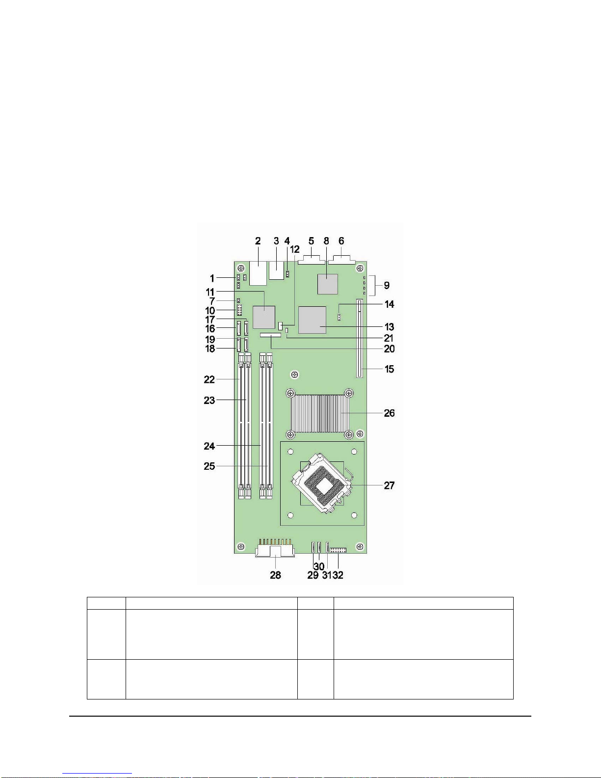
2.2 Server Board Layout
Ref # Description Ref # Description
1 (J1A2) BIOS Recovery Mode jumper
(J1A3) CMOS Clear jumper
(J1A4) Integrated BMC Boot Block Write
Protect jumper
2 (Bottom) USB Port 0
(Middle) USB Port 1
(Top) NIC1 RJ-45 connector
Revision 1.3
4
17 SATA Port 3
18 SATA Port 0
Intel order number E15331-006
Page 17

Intel® Server Board X38ML Server Board Overview
Ref # Description Ref # Description
3 NIC2 RJ-45 connector 19 SATA Port 1
4 (J3A1) Integrated BMC Force Update
Jumper
5 Serial A DB-9 connector 21 1x3 Serial B header
6 VGA connector 22 DIMM socket B2
7 Chassis intrusion header 23 DIMM socket B1
8 ServerEngines* Integrated BMC 24 DIMM socket A2
9 POST LED 25 DIMM socket A1
10 2x5 USB header for USB 2 and 3 26 Intel® X38 MCH
11 Intel® 82575EB LAN controller 27 LGA775 processor socket
12 SMBus connector 28 2x9 main power connector
13 Intel® 82801IR ICH9R 29 System fan 1 (8-pin)
14 (J6B1) Password Clear jumper 30 System fan 2 (8-pin)
15 PCI Express* x16 riser slot 31 System fan 3 (8-pin)
16 SATA Port 2 32 2x8 front panel connector
20 CMOS battery
Figure 1. Intel® Server Board X38ML Layout
The following mechanical drawing shows the physical dimensions of the server board:
Revision 1.3
5
Intel order number E15331-006
Page 18
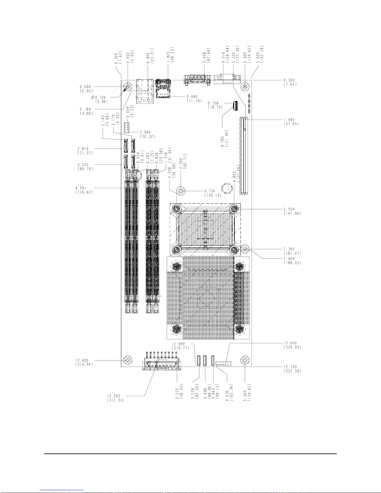
Server Board Overview Intel® Server Board X38ML
Figure 2. Intel® Server Board X38ML Mechanical Drawing
Revision 1.3
6
Intel order number E15331-006
Page 19
Intel® Server Board X38ML Functional Architecture
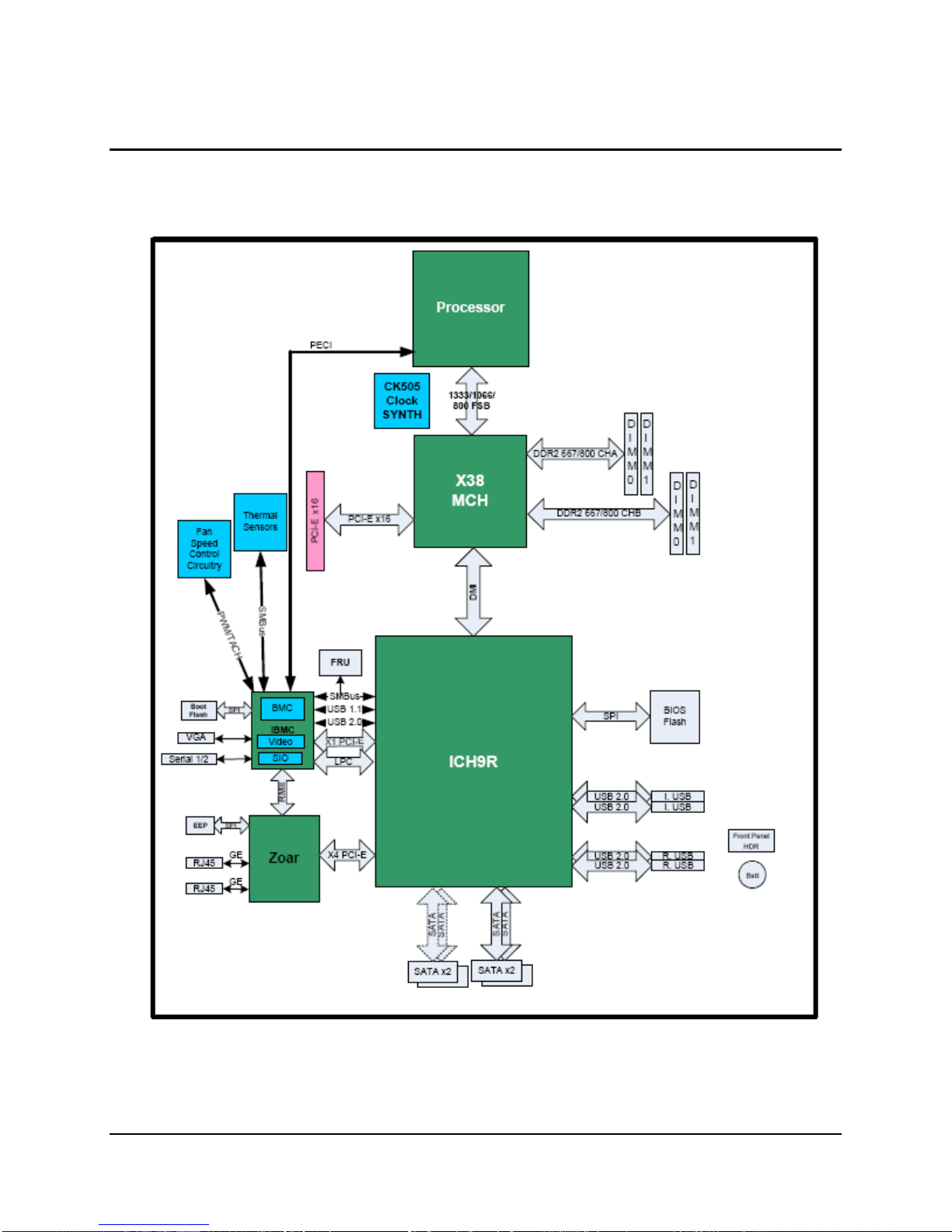
3. Functional Architecture
This chapter provides a high-level description of the functionality associated with the
architectural blocks that make up the server board.
(R)
Revision 1.3
Figure 3. Server Board Block Diagram
7
Intel order number E15331-006
Page 20

Functional Architecture Intel® Server Board X38ML
3.1 Processor Subsystem
The Intel® Server Board X38ML supports one Intel® Xeon® or workstation processor utilizing
Flip-Chip Land Grid Array (LGA) package technology, with an LGA775 socket. The supported
processors are based on the Intel
process technologies. They maintain compatibility with 32-bit software written for the IA-32
instruction set, while supporting 64-bit native mode operation when coupled with supported 64bit operating systems and applications. Previous generations of Intel
supported.
®
Core™ micro-architecture and built on 65 nm and 45 nm
®
processors are not
The processors supported with the Intel
®
Dual-Core Intel
Quad-Core Intel
Quad-Core Intel
®
Intel
Intel
Intel
The Intel
Intel
Intel
Intel
Intel
Core™2 Extreme Processor
®
Core™2 Duo Processor
®
Core™2 Quad Processor
®
Server Board X38ML does not provide support for the following processors:
®
Pentium® 4 Processor Extreme Edition
®
Pentium® D Processor
®
Pentium® 4 Processor
®
Celeron® D Processor
Xeon® Processor 3000 sequence
®
Xeon® Processor 3200 sequence
®
Xeon® Processor 3300 sequence
®
Server Board X38ML are listed below:
Table 1. Processor Support Matrix
Processor Family Processor Number Clock Speed Front Side Bus L2 Cache
Dual-Core Intel® Xeon® Processor 3000
sequence
Quad-Core Intel® Xeon® Processor 3200
sequence
Quad-Core Intel® Xeon® Processor 3300
sequence
Intel® Core™2 Extreme Edition X6800 2.93 GHz 1066 MHz 4 MB
Intel® Core™2 Duo E6300 1.86 GHz 1066 MHz 2 MB
Intel® Core™2 Quad Processor Q6600 2.40 GHz 1066 MHz 8 MB
Note: For a complete list of supported processors, refer to the Intel
3070
X3210
X3360
2.66 GHz 1066 MHz 4 MB
2.13 GHz 1066 MHz 8 MB
2.83 GHz 1333 MHz 12 MB
®
Server Board X38ML
support Web site: http://support.intel.com/support/motherboards/server/X38ML/.
3.2 Intel
®
X38 Chipset
The Intel® Server Board X38ML is designed around the Intel® X38 chipset. The chipset consists
of two components that work together to provide the interface between all major subsystems
found on the server board, including the processor, memory, and I/O subsystems. These
components are:
Memory Controller Hub (Intel
I/O Controller Hub (Intel
Revision 1.3
8
®
X38 MCH)
®
ICH9-R)
Intel order number E15331-006
Page 21

Intel® Server Board X38ML Functional Architecture
The following sub-sections provide an overview of the primary functions and supported features
of each chipset component as they are used on the Intel
®
Server Board X38ML. Later sections
provide more detail on the implementation of the subsystems.
3.2.1
Memory Controller Hub (MCH): Intel® X38 MCH
The MCH integrates four interfaces:
1. Processor/host interface (FSB)
- Supports LGA775 processors in a UP System configuration
- 200/266/333 MHz FSB clock frequency. Supports FSB transfer rates of
800/1066/1333 MT/s.
- GTL+ bus drivers with integrated GTL termination resistors
2. System memory interface (memory controller)
- Supports 512 Mbit, and 1 Gbit memory technologies
- DDR2 – 667, 800 MHz
- 8 GB addressable memory
- Supports unbuffered, ECC, and non-ECC DIMM
3. Direct media interface (DMI) interface
- Interface to the Intel
®
ICH9R South Bridge
- 100 MHz reference clock shared with PCI Express* interface(s)
4. PCI Express* interface
- Contains two PCI Express* x16 ports. One PCI Express* x16 port is connected to
one PCI Express* X16 connector as shown in the block diagram.
- Compliant with the PCI Express* base specification revision 2.0.
3.2.2
The Intel
I/O Controller Hub: Intel® ICH9-R
®
ICH9-R component integrates bridge functionality for PCI Express*, LPC, USB, SATA
II, IDE and SMBus, and numerous board management functions. The ICH9R is packaged in a
31 mm x 31 mm 676 pin mBGA.
3.2.2.1 Direct Media Interface (DMI)
DMI is the name given to chip-to-chip connection between the Intel
ICH9-R. DMI is an X4 link that mostly adheres to the PCI Express* specification. Deviations of
the DMI from standard PCI Express* specifications are described in the Intel
®
X38 MCH and the Intel®
®
ICH9 component
specification.
3.2.2.2 PCI Express* Interfaces
®
The Intel
ICH9R provides six PCI Express* Root Ports (GEN1), which are compliant with the
PCI Express Base Specification, Revision 1.1. The PCI Express* root ports 1-4 can be statically
configured as four x 1 ports, or ganged together to form two x 2 ports, one x 2 with two x1 ports,
or one x4 port. Ports 5 and 6 can be used as two x1 ports or one x2. The x4 configuration
supports lane reversal. Each Root Port fully supports 2.5 Gb/s bandwidth in each direction.
Revision 1.3
Intel order number E15331-006
9
Page 22

Functional Architecture Intel® Server Board X38ML
On the Intel® Server Board XM38ML, Root Ports 1-4 are ganged together to form a single x4
link connecting to an Intel
®
82575EB NIC controller. Port 5 is connected to the Integrated BMC
for 2D video function and Port 6 is not used.
3.2.2.3 Serial ATA II Interface
®
The Intel
ICH9R has an integrated SATA II host controller that supports independent DMA
operation on the six ports and supports data transfer rates of up to 300 MB/Sec. The SATA II
Controller provides two modes of operation – a legacy mode that uses I/O space and an
Advanced Host Controller Interface (AHCI) mode that uses memory space.
3.2.2.4 Low Pin Count Interface (LPC)
The low pin count interface on the Intel
®
ICH9R provides a low system cost design interface
solution for connecting the Super I/O (SIO) for the legacy interfaces such as the parallel port,
serial port, and floppy drive.
3.2.2.5 Compatibility Modules
The Intel
®
ICH9 incorporates compatibility modules such as DMA controller, timer/counters, and
interrupt controller. The DMA controller incorporates the logic of two 8237 DMA controllers, with
seven independently programmable channels. Channels 0 – 3 are hard-wired to 8-bit, count-bybyte transfers and channels 5 to 7 are hardwired to 16-bit, count-by-word transfers. DMA
Channel 4 is used to cascade the two 8327 controllers together. The DMA controller is used to
support the LPC DMA.
The LPC DMA is handled through the LDRQ# lines from peripherals and special encoding on
LAD[3:0] from the host.
The timer/counter block contains three counters that are equivalent in function to those found in
one 8254 programmable internal timer. These three counters are combined to provide the
system timer function and speaker tone. The 14.318 MHz oscillator input provides the clock
source for these three counters.
The Intel
®
ICH9 provides an ISA compatible Programmable Interrupt Controller (PIC) that
incorporates the functionality of two 8259 interrupt controllers. Each 8259 supports eight
interrupts that are cascaded via one master controller interrupt 2 for fifteen programmable
interrupts. The interrupts are for the system timer, keyboard controller, serial ports, parallel
ports, floppy disk, mouse, DMA channels, and mapped PCI-based interrupts.
3.2.2.6 Universal Serial Bus (USB) Controller
The Intel
®
ICH9 contains two EHCI and six UHCI USB Controllers providing support for twelve
USB 2.0 ports. All twelve ports are high speed, full-speed, and low speed capable. The port
routing logic for the ICH9 determines whether a USB port is controlled by one of the UHCI
controllers or by the EHCI controller. USB 2.0 based debug port is also implemented in the
ICH9.
Revision 1.3
10
Intel order number E15331-006
Page 23

Intel® Server Board X38ML Functional Architecture
3.2.2.7 Real Time Clock (RTC)
®
The Intel
two 128-byte banks of battery-backed RAM. The RTC performs two key functions on the Intel
ICH9 contains a Motorola MS146818A functionally compatible real-time clock with
®
Server Board XM38ML:
Keeps track of the time of day
Stores system configuration data even when the system is powered down
The RTC operates on a 32.768 KHz crystal and a 3 V lithium battery.
3.2.2.8 GPIO
®
The Intel
ICH9 contains 61 general purpose inputs/outputs. The General Purpose Inputs and
Outputs (GPIO) are provided for custom system design.
3.2.2.9 Enhanced Power Management
®
The Intel
that provides power and thermal management. The Intel
ICH9R supports the Advanced Configuration and Power Interface, Version 2.0 (ACPI)
®
ICH9R also supports the
Manageability Engine Power Management Support for new wake events from the MCH
Management Engine.
3.2.2.10 System Management Interface
The Intel
communicate with SMBus slaves. This interface is compatible with most I
®
ICH9R provides a SMBus 2.0 compliant Host Controller that allows the processor to
2
C devices. The
ICH9R also supports slave functionality. The SMBus logic exists in Device 31: Function 3
configuration space.
3.2.2.11 Serial Peripheral Interface (SPI)
The Serial Peripheral Interface (SPI) is a 4-pin interface that provides a potentially lower-cost
alternative for the system flash versus the Firmware Hub on the LPC Bus. The Intel
®
ICH9
supports two SPI flash components using two separate chip select pins. Each component may
be up to 16 MB and operate in SPI Fast Read Instructions and frequencies of 20 MHZ or 33
MHz. The SPI Interface has the following features:
Clock (CLK)
Master Out Slave In (MOSI)
Master In Slave Out (MISO)
Chip Select (CS#)
Communication on the SPI is done with a Master – Slave protocol.
The SPI flash can operate in two operational modes: descriptor and non-descriptor. When
operating in non-descriptor mode, the SPI Flash only supports the BIOS through register
access.
When used in descriptor mode, the ICH9 allows a single SPI flash device to store the system
BIOS, Intel
Revision 1.3
®
AMT Firmware, and Gigabit Ethernet EEPROM information.
11
Intel order number E15331-006
Page 24

Functional Architecture Intel® Server Board X38ML
The SPI Flash Memory device is an Atmel* AT26DF321 - a 32 mbit, 2.7 to 3.6 volt serial
interface FLASH memory, Intel part number D64145-001/D64145-002. This device is installed
directly onto the server board without the use of sockets.
3.2.2.12 Manageability
The Intel
®
ICH9 integrates several functions to manage the system and lower the total cost of
ownership (TCO) of the system. These system management functions report errors, diagnose
the system, and recover from system lockups without the aid of an external microcontroller.
The management engine includes the following features:
TCO timer to detect system locks
Process Present Indicator to determine if the processor fetches the first instruction after
reset
ECC Error reporting from the host controller
Function Disable to prevent a disabled function from generating interrupts and power
management events
Intruder Detect input for system cases
3.3 Integrated Baseboard Management Controller
A ServerEngines* Baseboard Management Controller (Integrated BMC) is integrated onto the
server board. This integrates the baseboard management controller (BMC and KVMS
subsystem), graphics controller (graphics subsystem), and Super I/O interface (Super I/O
subsystem). The Intel
3.3.1
Functionality Overview
Baseboard management controller
- IPMI 2.0 compliant
- Integrated 250 MHz 32-bit ARM9 processor
- Six I
2
- Two independent 10/100 Ethernet controllers with RMII support
- LPC master interface for non-volatile code storage
- SPI Flash interface
- Three UART for ICMB support
- DDR2 16-bit up to 667 MHz memory interface
- Sixteen mailbox registers for communication between the host and the BMC
- Watchdog timer
- Three general purpose timers
- Dedicated real-time clock for BMC
- Up to 16 direct and 64 serial GPIO ports
- Ability to maintain text and graphics controller history
- Twelve 10-bit analog to digital converters
®
Server Board XM38ML does not support remote KVMS features.
C SMBus Modules with master-slave support
Revision 1.3
12
Intel order number E15331-006
Page 25

Intel® Server Board X38ML Functional Architecture
- Three diode inputs for temperature measurements
- Eight fan tachometer inputs
- Four pulse width modulators (PWM)
- Chassis intrusion logic with battery-backed general purpose register
- LED support with programmable blink rate control
- Programmable I/O port snooping, which can be used to snoop on Port 80h
- Unique chip ID for each part, burned at the time production testing
- Hardware 32-bit random number generator
- JTAG master interface
- On-chip test Infrastructure for testing BMC firmware
Remote KVMS features
- USB 2.0 interface for keyboard, mouse, and remote storage such as CD-ROM/DVD-
ROM and floppy
- USB 1.1 interface for PS/2 to USB bridging, remote keyboard and mouse
- Hardware-based video compression and redirection logic
- Supports both text and graphics redirection
- Hardware-assisted video redirection using the frame processing engine
- Direct interface to the Integrated Graphics Controller registers and Frame buffer
- Hardware-based encryption engine
Graphics controller
- Integrated graphics core
- 2D hardware graphics acceleration
- DDR2 memory interface supports up to 128 Mbytes of memory
- Supports all display resolutions up to 1600 x 1200 16 bpp @ 75 Hz
- High speed integrated 24-bit RAMDAC
- Single lane PCI Express* host interface
Server Class Super I/O functionality includes
- Keyboard style/BT interface for BMC support
- Two fully functional serial ports, compatible with the 16C550
- Serial IRQ support
- SMI/SCI/PME support
- ACPI-compliant
- Up to 16 shared GPIO ports
- Programmable wake-up event support
- Plug and play register set
- Power supply control
- Watchdog timer compliant with Microsoft SHDG
- LPC to SPI bridge for system BIOS support
- Real-time clock module with the external RTC interface
Revision 1.3
13
Intel order number E15331-006
Page 26

Functional Architecture Intel® Server Board X38ML
3.3.2 Block Diagram
The following block diagram shows the three main host interface of the integrated BMC. The
LPC, PCI Express*, and USB interfaces are resourced by the Intel
Board X38ML.
The LPC interface to the host is used for the Super I/O and BMC functionality. The BMC can
communicate with the host through the KCS or BT interfaces. The Super I/O interface also
integrates a LPC to SPI Flash bridge, which can be used to store multiple copies of the system
ROM.
The PCI Express* interface is mainly used for the graphics controller interface to the host. The
graphics controller is a fully compliant VGA controller with 2D hardware acceleration and full
bus master support. The graphics controller can support up to 1600 x1200 resolutions at high
refresh rates.
The USB 1.1 is used for the remote keyboard and mouse support and the USB2.0 is used for
the remote storage support. The Integrated BMC supports various storage devices such as CDROM, DVD-ROM, CD-ROM (ISO image), floppy, and USB flash disk. Any of the storage devices
can be used as a boot device and the host can boot from this remote media.
®
ICH9R on the Intel® Server
Revision 1.3
14
Intel order number E15331-006
Page 27

Intel® Server Board X38ML Functional Architecture
Figure 4. Integrated BMC Block Diagram
3.4 Memory Subsystem
3.4.1 Memory Support
The server board supports four DDR2 667/800 MHz unbuffered ECC or non-ECC DIMMs, two
memory channels, two DIMMs per memory channel. The maximum memory capacity supported
is 8 GB using four DIMMs of 2 GB unbuffered, 1 Gbit DDR2 memory.
Only DIMMs tested and qualified by Intel or a designated memory test vendor are supported. A
list of qualified DIMMs is at http://support.intel.com/support/motherboards/server/X38ML/
Note: All DIMMs are supported by design, but only fully qualified DIMMs are supported on the
board.
3.4.2 Memory Population Rules
The X38 MCH supports two DDR2 DIMM sockets for Channel A, and two DDR2 DIMM sockets
for Channel B. The four slots are partitioned with Channel A representing the Channel A DIMMs
Revision 1.3
Intel order number E15331-006
.
15
Page 28

Functional Architecture Intel® Server Board X38ML
(DIMM A1 and DIMM A2) and Channel B representing the Channel B DIMMs (DIMM B1 and
DIMM B2). They are placed in a row and numbered as DIMM A1/DIMM A2/DIMM B1/DIMM B2
with DIMM A1 the closest to the MCH.
Memory population rules:
If dual-channel operation is desired, Channel A and Channel B must be populated
identically (for example, same capacity)
Use DDR2 667/800 only
The speed used on all the channels is the slowest DIMM in the system
Use ECC or non-ECC DIMMs
User can mix different memory technologies (size and density)
For single-channel mode, either channel may be used and DIMM sockets within the
same channel can be populated in any order
For dual-channel interleaved mode, DIMM sockets may be populated in any order as
long as the total memory in each channel is the same.
For dual-channel asymmetric mode, DIMM sockets may be populated in any order.
3.5 I/O Subsystem
3.5.1 PCI Express* x16 Riser Slot
The server board provides a PCI Express* x16 riser slot that is resourced with a PCI Express*
x16 interface from MCH and supports PCI Express* x16 graphics.
3.5.2 SATA Support
The server board provides four SATA II ports by the integrated SATA controller of the Intel®
ICH9-R. The SATA controller supports data transfer rates of up to 300 MB/sec and provides two
modes of operation: a legacy mode using I/O space and an Advanced Host Controller Interface
(AHCI) mode using memory space.
3.5.2.1 SATA RAID
®
Intel
Embedded Server RAID Technology, available with the CH9R, supports four Serial ATA
ports, providing a cost-effective way to achieve higher transfer rates and reliability. Intel
Embedded Server RAID Technology supports:
RAID level 0 data striping for improved performance
RAID level 1 data mirroring for improved data reliability
RAID level 10 data striping and mirroring for high data transfer rates and data
redundancy
®
Revision 1.3
16
Intel order number E15331-006
Page 29

Intel® Server Board X38ML Functional Architecture
Intel® Embedded Server RAID Technology functionality requires the following items:
Intel
Intel
Most recent version of the Intel
®
ICH9-R
®
RAID Technology option ROM
®
Application Accelerator RAID Edition drivers
Two SATA hard drives
®
RAID Technology is not available in these configurations:
Intel
The SATA controller in compatible mode
Intel
®
RAID Technology disabled
3.5.2.2 Intel
®
The Intel
RAID Technology for SATA Option ROM provides a pre-operating system user
®
RAID Technology Option ROM
interface for the Intel RAID Technology implementation and provides the ability for an Intel RAID
Technology volume to be used as a boot disk as well as to detect any faults in the Intel RAID
Technology volume(s) attached to the Intel RAID controller.
3.5.3 Video Support
The Integrated BMC integrates a fully compliant VGA graphics controller with hardware
acceleration for BLIT and 2D graphics. The graphics controller:
Is resourced with a PCI Express* x1 interface from the ICH9R
Supports 16-bit DDR2 memory running at a configurable frequency of 500 MHz. The
maximum capacity is 128 MB.
Supports all display resolutions up to 1600 x 1200 16bpp @ 75Hz
3.5.4 Network Interface Controller (NIC)
The server board integrates an Intel® 82575EB Gigabit Ethernet Controller to provide two
Gigabit Ethernet Ports. The NIC is resourced with a PCI Express* x4 interface from the ICH9R.
The NIC supports the following features:
PCI Express* x4 interface
IEEE 802.3x compliant flow control support
Integrated PHY for full 10/100/1000 Mbps full and half duplex operation
On-board microcontroller
Wake-On LAN support
3.5.5 USB Support
The server board provides up to four USB 2.0 ports by the USB controller functionality
integrated into the ICH9-R. Two external connectors are located on the back edge of the
Revision 1.3
17
Intel order number E15331-006
Page 30

Functional Architecture Intel® Server Board X38ML
baseboard. One 10-pin internal on-board header is provided which is capable of supporting two
additional USB 2.0 ports.
3.5.6 Super I/O Chip
The Super I/O chip integrated into the Integrated BMC provides legacy I/O support. The Super
I/O chip contains the necessary circuitry to support two serial ports and hardware
control/monitor functions. The server board implements the following features:
Two fully functional serial ports, compatible with the 16C550
Up to 16 shared GPIO ports
Programmable wake-up event support
Plug and play register set
Power supply control
Watchdog timer compliant with Microsoft SHDG*
LPC to SPI bridge for system BIOS support
Real-time clock module with the external RTC interface
3.5.6.1 Serial Ports
The board provides two serial ports. Serial A is a standard DB-9 interface located at the rear I/O
panel of the server board next to the video connector. The reference designator is J5A1. Serial
B is a 3-pin header interface located near the CMOS battery. The reference designator is J4C1.
Table 2. Serial A Header Pin-out
Pin Signal Name Serial Port A Header Pin-out
1 DCD
2 RXD
3 TXD
4 DTR
5 GND
6 DSR
7 RTS
8 CTS
9 RI
Revision 1.3
18
Intel order number E15331-006
Page 31

Intel® Server Board X38ML Functional Architecture
Table 3. Serial B Header Pin-out
Pin Signal Name Serial Port B Header Pin-out
1 RXD
2 GND
3 TXD
3-pin Serial B header
1
Rx
2
GND
3
Tx
3.5.6.2 Keyboard and Mouse Support
USB ports can be used to support keyboard and mouse. No PS/2 port is provided.
3.5.6.3 Wake-up Control
The Super I/O contains functionality that allows various events to control the power-on and
power-off the system.
3.6 Replacing the Back-Up Battery
The lithium battery on the server board powers the RTC for up to ten years in the absence of
power. When the battery starts to weaken, it loses voltage, and the server settings stored in
CMOS RAM in the RTC (for example, the date and time) may be incorrect. Contact your
customer service representative or dealer for a list of approved devices.
WARNING
Danger of explosion,if battery is incorrectly replaced. Replace only with the same or equivalent
type recommended by the equipment manufacturer. Discard used batteries according to
manufacturer’s instructions.
ADVARSEL!
Lithiumbatteri - Eksplosionsfare ved fejlagtig håndtering. Udskiftning må kun ske med batteri af
samme fabrikat og type. Levér det brugte batteri tilbage til leverandøren.
ADVARSEL
Lithiumbatteri - Eksplosjonsfare. Ved utskifting benyttes kun batteri som anbefalt av
apparatfabrikanten. Brukt batteri returneres apparatleverandøren.
VARNING
Revision 1.3
19
Intel order number E15331-006
Page 32

Functional Architecture Intel® Server Board X38ML
Explosionsfara vid felaktigt batteribyte. Använd samma batterityp eller en ekvivalent typ som
rekommenderas av apparattillverkaren. Kassera använt batteri enligt fabrikantens instruktion.
VAROITUS
Paristo voi räjähtää, jos se on virheellisesti asennettu. Vaihda paristo ainoastaan
laitevalmistajan suosittelemaan tyyppiin. Hävitä käytetty paristo valmistajan ohjeiden mukaisesti.
Revision 1.3
20
Intel order number E15331-006
Page 33

Intel® Server Board X38ML System BIOS
4. System BIOS
4.1 BIOS Identification String
The BIOS identification string uniquely identifies the revision of the BIOS. The string is formatted
as follows:
BoardFamilyID.OEMID.MajorRev.MinorRev.BuildID.BuildDateTime
Where:
BoardFamilyID = String name for this board family
OEMID = Three-character OEM ID. “86B” is used for Intel
MajorRev = Two decimal digits
MinorRev = Two decimal digits
BuildID = Four decimal digits
BuildDateTime = Build date and time in MMDDYYYYHHMM format:
- MM = Two-digit month
- DD = Two-digit day of month
- YYYY = Four-digit year
- HH = Two-digit hour using 24-hour clock
- M = Two-digit minute
For example, BIOS Build 3, generated on Jan 21, 2006 at 11:59 AM has the following BIOS ID
string displayed in the POST diagnostic screen:
®
Server Boards
S3200X38.86B.01.00.0003.012120061159
The BIOS version in the Setup Utility is displayed as:
S3200X38.86B.01.00.0003
The BIOS ID is identifies the BIOS image. It is not used to designate the board ID (S3200X38)
or the BIOS phase (Alpha, Beta, and so on). Support for INT15H, Function DA8Ch (Get
BIOSID) was removed. The BIOS ID is available in the SMBIOS type 0 structure and in BIOS
Setup.
The Board ID is available in the SMBIOS type 2 structure and in BIOS Setup. You can
determine the phase of the BIOS by the release notes associated with the image.
4.2 Logo/Diagnostic Screen
The Logo/Diagnostic Screen is in one of two forms given below:
Revision 1.3
Intel order number E15331-006
21
Page 34

System BIOS Intel® Server Board X38ML
If Quiet Boot is enabled in BIOS Setup, a logo splash screen is displayed. By default,
Quiet Boot is enabled in BIOS Setup. If the logo is displayed during POST, pressing
<Esc> hides the logo and displays the diagnostic screen.
If no logo is present in the flash ROM or if Quiet Boot is disabled in the BIOS Setup, the
summary and diagnostic screen is displayed.
The diagnostic screen consists of this information:
BIOS ID
Platform name
Total memory detected (Total size of all installed DIMMs)
Processor information (Intel branded string, speed, and number of physical processors
identified)
Types of keyboards detected if plugged in (USB)
Types of mouse devices detected if plugged in (USB)
4.3 BIOS Setup Utility
The BIOS Setup utility is a text-based utility that allows the user to configure the system and
view current settings and environment information for the platform devices. The Setup utility
controls the platform's built-in devices, boot manager, and error manager.
The BIOS Setup utility interface consists of a number of pages or screens. Each page contains
information or links to other pages. The Advanced tab in Setup displays a list of general
categories as links. These links lead to pages containing a specific category’s configuration.
The following sections describe the look and behavior for BIOS Setup.
4.3.1 Operation
The BIOS Setup utility is only available in English. It is functional via console redirection over
various terminal emulation standards. This may limit some functionality for compatibility (for
example, usage of colors or some keys or key sequences or support of pointing devices).
4.3.1.1 Setup Page Layout
The Setup utility page layout is sectioned into functional areas. Each occupies a specific area of
the screen and has dedicated functionality as described by the table:
Table 4. BIOS Setup Page Layout
Functional Area Description
Title Bar The title bar is located at the top of the screen and displays the title of the form
(page) the user is currently viewing. It may also display navigational information.
Setup Item List The Setup Item List is a set of controllable and informational items. Each item in the
list occupies the left and center columns in the middle of the screen. The left
column, the "Setup Item", is the subject of the item. The middle column, the
"Option", contains an informational value or choices of the subject.
Revision 1.3
22
Intel order number E15331-006
Page 35

Intel® Server Board X38ML System BIOS
Functional Area Description
A Setup Item may also be a hyperlink used to navigate form sets (pages). When it is
a hyperlink, a Setup Item only occupies the “Setup Item” column.
Item Specific Help Area The Item Specific Help area is located on the right side of the screen and contains
help text for the highlighted Setup Item. Help information includes the meaning and
usage of the item, allowable values, effects of the options, and so on.
Keyboard Command Bar The Keyboard Command Bar is located at the bottom right of the screen and
continuously displays help for keyboard special keys and navigation keys. The
keyboard command bar is context-sensitive—it displays keys relevant to current
page and mode.
4.3.1.2 Entering BIOS Setup
The BIOS Setup utility is initiated by pressing <F2> during system boot when the OEM or Intel
logo is displayed.
When Quiet Boot is disabled, the following message is displayed on the diagnostics screen:
Press <F2> to enter setup.
Serious errors cause the system to enter the BIOS setup. The error manager screen will display
in this occurrence.
4.3.1.3 Keyboard Commands
The bottom right portion of the Setup screen provides a list of commands to navigate through
the Setup utility. These commands are displayed at all times.
Except for features used for informative purposes, each feature on each Setup menu page is
associated with a value field. This field contains user-selectable parameters. Depending on the
security option chosen and in effect by the password, a menu feature’s value may or may not be
changeable. If a value is non-changeable, the feature’s value field is inaccessible and displays
as “grayed out.”
The Keyboard Command Bar supports the following:
Table 5. BIOS Setup: Keyboard Command Bar
Key Option Description
<Enter> Execute
Command
The <Enter> key is used to activate sub-menus when the selected feature is a submenu, or to display a pick list if a selected option has a value field, or to select a
sub-field for multi-valued features such as time and date. If a pick list is displayed,
the <Enter> key will select the currently highlighted item, undo the pick list, and
return the focus to the parent menu.
Revision 1.3
23
Intel order number E15331-006
Page 36

System BIOS Intel® Server Board X38ML
Key Option Description
<Esc> Exit The <Esc> key provides a mechanism for backing out of any field. When the <Esc>
key is pressed while editing any field or selecting features of a menu, the parent
menu is re-entered.
When the <Esc> key is pressed in any sub-menu, the parent menu is re-entered.
When the <Esc> key is pressed in any major menu, the exit confirmation window is
displayed and the user is asked whether changes can be discarded. If “No” is
selected and the <Enter> key is pressed, or if the <Esc> key is pressed, the user is
returned to where he/she was before <Esc> was pressed, without affecting any
existing settings. If “Yes” is selected and the <Enter> key is pressed, setup is
exited and the BIOS returns to the main System Options Menu screen.
<Tab> Select Field The <Tab> key is used to move between fields. For example, you can use <Tab>
- Change Value The minus key on the keypad is used to change the value of the current item to the
+ Change Value The plus key on the keypad is used to change the value of the current menu item to
<F9> Setup Defaults Pressing <F9> causes the following to display:
<F10> Save and Exit Pressing <F10> causes the following message to display:
Select Item The up arrow is used to select the previous value in a pick list, or the previous
option in a menu item's option list. The selected item must then be activated by
pressing the <Enter> key.
Select Item The down arrow is used to select the next value in a menu item’s option list, or a
value field’s pick list. The selected item must then be activated by pressing the
<Enter> key.
Select Menu The left and right arrow keys are used to move between the major menu pages.
The keys have no effect if a sub-menu or pick list is displayed.
to move from hours to minutes in the time item in the main menu.
previous value. This key scrolls through the values in the associated pick list
without displaying the full list.
the next value. This key scrolls through the values in the associated pick list without
displaying the full list. On 106-key Japanese keyboards, the plus key has a different
scan code than the plus key on the other keyboard, but will have the same effect.
Load Optimized Defaults?
Yes No
If Yes is highlighted and <Enter> is pressed, all Setup fields are set to their default
values. If No is highlighted and <Enter> is pressed, or if the <Esc> key is pressed,
the user is returned to where they were before <F9> was pressed without affecting
any existing field values.
Save configuration and reset?
Yes No
If Yes is highlighted and <Enter> is pressed, all changes are saved and Setup is
exited. If No is highlighted and <Enter> is pressed, or the <Esc> key is pressed, the
user is returned to where they were before <F10> was pressed without affecting
any existing values.
4.3.1.4 Menu Selection Bar
The Menu Selection Bar is located at the top of the BIOS Setup utility screen. It displays the
major menu selections available to the user. By using the left and right arrow keys, the user can
Revision 1.3
24
Intel order number E15331-006
Page 37

Intel® Server Board X38ML System BIOS
select the menus listed. Some menus are hidden and become available by scrolling to the left or
right of the selections.
4.3.2 BIOS Setup Screens
The following sections describe the screens available for the configuration of a server platform.
In these sections, tables are used to describe the contents of each screen. These tables follow
these guidelines:
The text and values in the Setup Item, Options, and Help columns in the tables are
displayed on the BIOS Setup screens.
Bold text in the Options column of the tables indicates default values. These values are
not displayed in bold on the setup screen. The bold text in this document is to serve as a
reference point.
The Comments column provides additional information where it may be helpful. This
information does not display in the BIOS Setup screens.
Information in the screen shots that is enclosed in brackets (< >) indicates text that
varies, depending on the option(s) installed. For example, <Current Date> is replaced by
the actual current date.
Information that is enclosed in square brackets ([ ]) in the tables indicates areas where
the user needs to type in text instead of selecting from a provided option.
Whenever information is changed (except Date and Time), the systems requires a save
and reboot to take place. Pressing <ESC> discards the changes and boots the system
according to the boot order set from the last boot.
4.3.2.1 Main Screen
The Main screen is the screen that is first displays when the BIOS Setup is entered, unless an
error has occurred. If an error occurred, the Error Manager screen displays instead.
Revision 1.3
25
Intel order number E15331-006
Page 38

System BIOS Intel® Server Board X38ML
Main
Advance
d
Security Server Management Boot Options Boot Manager
Logged in as <Administrator or User>
Platform ID
<Platform Identification String>
BIOS Version
S3200X38.86B.xx.yy.zzzz
Build Date
<MM/DD/YYYY>
Processor
Intel® Xeon® CPU
Core Frequency <Current Operating Frequency>
Memory
Size <How much memory is installed>
Quiet Boot Enabled/Disabled
POST Error Pause Enabled/Disabled
System Date <Current Date>
System Time <Current Time>
Figure 5. Setup Utility — Main Screen Display
Setup Item Options Help Text Comments
Logged in as N/A N/A
Platform ID N/A N/A
BIOS Version N/A N/A
Revision 1.3
26
Table 6. Setup Utility — Main Screen Fields
Information only. Displays
password level that setup is
running in, Administrator or User.
With no passwords set,
Administrator is the default mode.
Information only. Displays the
Platform ID.
Information only. Displays the
current BIOS version.
xx = major version
yy = minor version
zzzz = build number
Intel order number E15331-006
Page 39

Intel® Server Board X38ML System BIOS
Setup Item Options Help Text Comments
Build Date N/A N/A
Processor
<ID string from the
Processor>
Core Frequency N/A N/A
Count N/A N/A
Memory
Size N/A N/A
Quiet Boot
POST Error Pause Enabled
System Date [Day of week
System Time [HH:MM:SS] System Time has configurable
N/A N/A
Enabled
Disabled
Disabled
MM/DD/YYYY]
[Enabled] – Display the logo screen
during POST.
[Disabled] – Display the diagnostic
screen during POST.
[Enabled] – Go to the Error
Manager for critical POST errors.
[Disabled] – Attempt to boot and do
not go to the Error Manager for
critical POST errors.
System Date has configurable
fields for Month, Day, and Year.
Use [Enter] or [Tab] key to select
the next field.
Use [+] or [-] key to modify the
selected field.
fields for Hours, Minutes, and
Seconds.
Hours are in 24-hour format.
Use [Enter] or [Tab] key to select
the next field.
Use [+] or [-] key to modify the
selected field.
Information only. Displays the
current BIOS build date.
Information only. Displays the
Intel processor name and the
speed of the CPU. This information
is retrieved from the processor.
Information only. Displays the
current speed of the boot processor
in GHz or MHz.
Information only. Number of
physical processors detected.
Information only. Displays the
total physical memory installed in
the system in MB or GB. The term
physical memory indicates the total
memory discovered in the form of
installed DIMMs.
N/A
The POST error pause takes the
system to the error manager to
review the errors when Major errors
occur. Minor and Fatal error
displays are not affected by this
setting. See Section 6.3.3 for more
information.
N/A
N/A
4.3.2.2 Advanced Screen
The Advanced screen provides an access point to choose to configure several options. On this
screen, the user selects the option that is to be configured. Configurations are performed on the
selected screen, not directly on the Advanced screen.
To access this screen from the Main screen, select Advanced.
Revision 1.3
27
Intel order number E15331-006
Page 40

System BIOS Intel® Server Board X38ML
Main
Advance
d
Security Server Management Boot Options Boot Manager
► Processor Configuration
► Memory Configuration
► SATA Controller Configuration
► Serial Port Configuration
► USB Configuration
► PCI Configuration
Figure 6. Setup Utility — Advanced Screen Display
Table 7. Setup Utility — Advanced Screen Display Fields
Setup Item Options Help Text Comments
Processor Configuration N/A View/Configure processor information
and settings.
Memory Configuration N/A View/Configure memory information and
settings.
SATA Controller Configuration N/A View/Configure SATA Controller
information and settings.
Serial Port Configuration N/A View/Configure serial port information
and settings.
USB Configuration
PCI Configuration
N/A View/Configure USB information and
settings.
N/A View/Configure PCI information and
settings.
N/A
N/A
N/A
N/A
N/A
N/A
4.3.2.2.1 Processor Configuration Screen
The Processor Configuration screen provides a place to view the processor core frequency,
system bus frequency, and enable or disable several processor options. The user can also
select an option to view information about a specific processor.
To access this screen from the Main screen, select Advanced > Processor.
Revision 1.3
28
Intel order number E15331-006
Page 41

Intel® Server Board X38ML System BIOS
Advanced
Processor Configuration
Processor Family <String from Processor>
Core Frequency <Current Processor Frequency>
Maximum Frequency <Maximum Processor Speed>
System Bus Frequency <Current FSB Frequency>
L2 Cache Size <Size of the cache>
Processor Stepping <Stepping # of this processor>
CPUID Register <CPUID>
Hyper-Threading Technology Enabled/Disabled
Enhanced Intel
Core Multi-processing Enabled/Disabled
®
Intel
Virtualization Technology Enabled/ Disabled
Execute Disable Bit Enabled/Disabled
®
SpeedStep Tech Enabled/Disabled
Figure 7. Setup Utility — Processor Configuration Screen Display
Table 8. Setup Utility — Processor Configuration Screen Fields
Setup Item Options Help Text Comments
Processor Family N/A N/A
Core Frequency N/A N/A
Maximum
Frequency
System Bus
Frequency
L2 Cache RAM N/A N/A
Processor Stepping N/A N/A
CPUID Register N/A N/A
N/A N/A
N/A N/A
Information only. Identifies
family or generation of the
processor.
Information only. Frequency
at which processors currently
run.
Information only. Maximum
frequency the processor core
supports.
Information only. Current
frequency of the processor front
side bus.
Information only. Size of the
processor L2 cache.
Information only. Stepping
number of the processor.
Information only. CPUID
register value identifies details
about the processor family,
model, and stepping.
Revision 1.3
29
Intel order number E15331-006
Page 42

System BIOS Intel® Server Board X38ML
Setup Item Options Help Text Comments
Hyper-Threading
Technology
Enhanced Intel®
SpeedStep
Technology
Core Multiprocessing
Intel® Virtualization
Technology
Execute Disable Bit
Enabled
Disabled
Enabled
Disabled
Enabled
Disabled
Enabled
Disabled
Enabled
Disabled
Hyper-Threading Technology allows
multi-threaded software applications
to execute threads in parallel within
each processor.
Contact your operating system
vendor regarding operating system
support of this feature.
Enhanced Intel SpeedStep
Technology allows the system to
dynamically adjust processor voltage
and core frequency, which can result
in decreased average power
consumption and decreased average
heat production.
Contact your operating system
vendor regarding operating system
support of this feature.
Core Multi-processing sets the state
of logical processor cores in a
package. [Disabled] sets only logical
processor core 0 as enabled in each
processor package.
Note: If disabled, Hyper-Threading
Technology is also automatically
disabled.
Intel® Virtualization Technology
allows a platform to run multiple
operating systems and applications in
independent partitions.
Note: A change to this option
requires the system to be powered off
and then back on before the setting
takes effect.
Execute Disable Bit can help prevent
certain classes of malicious buffer
overflow attacks.
Contact your operating system
vendor regarding operating system
support of this feature.
®
This option is automatically
disabled when Dual Core is
disabled.
N/A
N/A
N/A
N/A
4.3.2.2.2 Memory Configuration Screen
The Memory Configuration screen provides a place to view details about the system memory
DIMMs installed. On this screen, the user can select an option to open the Configure Memory
RAS and Performance screen.
To access this screen from the Main screen, select Advanced > Memory.
Revision 1.3
30
Intel order number E15331-006
Page 43

Intel® Server Board X38ML System BIOS
Advanced
Memory Configuration
Total Memory <Total Physical Memory Installed in System>
Effective Memory <Total Effective Memory>
Current Configuration < Single Channel/Dual Channel >
Current Memory Speed <Speed that installed memory is running at.>
DIMM Information
DIMM_A1 Installed/Not Installed/Failed
DIMM_A2 Installed/Not Installed/Failed
DIMM_B1 Installed/Not Installed/Failed
DIMM_B2 Installed/Not Installed/Failed
Memory Correction ECC/Non-ECC
Figure 8. Setup Utility — Memory Configuration Screen Display
Table 9. Setup Utility — Memory Configuration Screen Fields
Setup Item Options Help Text Comments
Total Memory N/A N/A
Effective Memory N/A N/A
Current Configuration N/A N/A
Information only. The amount of memory
available in the system in the form of
installed DIMMs in units of MB or GB.
Information only. The amount of memory
available to the operating system in MB or
GB.
The Effective Memory is the difference
between Total Physical Memory and the
sum of all memory reserved for internal
usage. This difference includes the sum of
all DIMMs that failed Memory Test during
POST.
Information only. Displays one of the
following:
Dual Channel: System memory is
configured for optimal performance
and efficiency.
Single Channel: System memory is
functioning in a special, reduced
efficiency mode.
Revision 1.3
31
Intel order number E15331-006
Page 44

System BIOS Intel® Server Board X38ML
Setup Item Options Help Text Comments
Current Memory
Speed
DIMM_# N/A N/A Displays the state of each DIMM socket
Memory Correction
N/A N/A
ECC
Non-ECC
N/A N/A
Information only. Displays speed the
memory is running at.
present on the board. Each DIMM socket
field reflects one of the following possible
states:
Installed: There is a DIMM installed
in this slot.
Not Installed: There is no DIMM
installed in this slot.
Failed: The DIMM installed in this
slot is faulty/malfunctioning.
4.3.2.2.3 SATA Controller Configuration Screen
The SATA Controller Configuration screen provides fields to configure SATA hard drives. It also
provides information on the hard disk drives installed.
To access this screen from the Main screen, select Advanced | SATA Controller.
Advanced
SATA Controller Configuration
Onboard SATA Controller Enabled/Disabled
Configure SATA as IDE/AHCI/ RAID
► SATA Port 0 Not Installed/<Drive Info.>
► SATA Port 1 Not Installed/<Drive Info.>
► SATA Port 2 Not Installed/<Drive Info.>
► SATA Port 3 Not Installed/<Drive Info.>
Figure 9. Setup Utility — ATA Controller Configuration Screen Display
Revision 1.3
32
Intel order number E15331-006
Page 45

Intel® Server Board X38ML System BIOS
Table 10. Setup Utility — ATA Controller Configuration Screen Fields
Setup Item Options Help Text Comments
Onboard SATA
Controller
Configure SATA as
SATA Port 0 < Not Installed/Drive
SATA Port 1 < Not Installed/Drive
SATA Port 2 < Not Installed/Drive
SATA Port 3 < Not Installed/Drive
Enabled
Disabled
IDE
AHCI
RAID
information>
information>
information>
information>
Onboard Serial ATA (SATA)
controller.
[IDE] - SATA controller will be in
IDE legacy mode.
[AHCI] - Advanced Host
Controller Interface (AHCI)
option ROM will enumerate all
AHCI devices connected to the
SATA ports.
Contact your OS vendor
regarding OS support of this
feature.
[RAID] - SATA controller will be
in RAID mode and the Intel
RAID for Serial ATA option ROM
will execute.
N/A
N/A
N/A
N/A
®
When enabled, the SATA
controller can be configured in
IDE, RAID, or AHCI Mode. RAID
and AHCI modes are mutually
exclusive.
When AHCI is selected:
The identification and
configuration is left to the AHCI
Option ROM. Only devices
supported by the AHCI Option
ROM are displayed in setup
(SATA HDD and SATA CDROM)
other devices are available in the
operating system after their
drivers are loaded.
When RAID is selected, no SATA
drive information is displayed.
Information only; Unavailable
when RAID Mode is enabled.
Information only; This field is
unavailable when RAID Mode is
enabled.
Information only; This field is
unavailable when RAID Mode is
enabled.
Information only; This field is
unavailable when RAID Mode is
enabled.
4.3.2.2.4 Serial Ports Screen
The Serial Ports screen provides fields to configure the Serial A [COM 1] and Serial B [COM2].
To access this screen from the Main screen, select Advanced > Serial Port.
Revision 1.3
Intel order number E15331-006
33
Page 46

System BIOS Intel® Server Board X38ML
Advanced
Serial Port Configuration
Serial A Enable Enabled/Disabled
Address 3F8h/2F8h/3E8h/2E8h
IRQ 3 or 4
Serial B Enable Enabled/Disabled
Address 3F8h/2F8h/3E8h/2E8h
IRQ 3 or 4
Figure 10. Setup Utility — Serial Port Configuration Screen Display
Table 11. Setup Utility — Serial Ports Configuration Screen Fields
Setup Item Options Help Text Comments
Serial A
Enable
Address
IRQ 3 4 Select Serial port A base interrupt request (IRQ)
Serial B
Enable
Address 3F8h
IRQ
Enabled
Disabled
3F8h
2F8h
3E8h
2E8h
Enabled
Disabled
2F8h
3E8h
2E8h
3
4
Enable or Disable Serial port A.
Select Serial port A base I/O address. N/A
line.
Enable or Disable Serial port B.
Select Serial port B base I/O address. N/A
Select Serial port B base interrupt request (IRQ)
line.
N/A
N/A
N/A
N/A
4.3.2.2.5 USB Configuration Screen
The USB Configuration screen provides fields to configure the USB controller options.
To access this screen from the Main screen, select Advanced > USB Configuration.
Revision 1.3
34
Intel order number E15331-006
Page 47

Intel® Server Board X38ML System BIOS
Advanced
USB Configuration
Detected USB Devices
<All USB Devices in System>
USB Controller Enabled/Disabled
Legacy USB Support Enabled/Disabled/Auto
USB Mass Storage Device Configuration
Device Reset timeout 10 sec/20 sec/30 sec/40 sec
Storage Emulation
<Mass storage devices one line/device> Auto/Floppy/Forced FDD/Hard Disk/CD-ROM
USB 2.0 controller Enabled/Disabled
Figure 11. Setup Utility — USB Controller Configuration Screen Display
Revision 1.3
35
Intel order number E15331-006
Page 48

System BIOS Intel® Server Board X38ML
Table 12. Setup Utility — USB Controller Configuration Screen Fields
Setup Item Options Help Text Comments
Detected
USB Devices
USB
Controller
Legacy USB
Support
Device Reset
timeout
Storage Emulation
One line for
each mass
storage
device in
system
USB 2.0
controller
N/A N/A
Enabled
Disabled
Enabled
Disabled
Auto
10 sec
20 sec
30 sec
40 sec
Auto
Floppy
Forced FDD
Hard Disk
CD-ROM
Enabled
Disabled
[Enabled] - All onboard USB controllers will be turned on
and accessible by the OS.
[Disabled] - All onboard USB controllers will be turned off
and inaccessible by the OS.
PS/2 emulation for USB keyboard and USB mouse
devices.
[Auto] - Legacy USB support will be enabled if a USB
device is attached.
USB Mass storage device Start Unit command timeout. N/A
[Auto] - USB devices less than 530 MB will be emulated as
floppy.
[Forced FDD] - HDD formatted drive will be emulated as
FDD (e.g., ZIP drive).
Onboard USB ports will be enabled to support USB 2.0
mode.
Contact your OS vendor regarding OS support of this
feature.
Information only: Shows all
USB devices in the system.
N/A
N/A
Header for next line.
This setup screen can show a
maximum of eight devices on
this screen. If more than 8
devices are installed in the
system, the ‘USB Devices
Enabled’ shows the correct
count, but only displays the
first eight devices.
N/A
4.3.2.2.6 PCI Screen
The PCI Screen provides fields to configure PCI add-in cards, the onboard NIC controllers, and
video options.
To access this screen from the Main screen, select Advanced > PCI.
Revision 1.3
36
Intel order number E15331-006
Page 49

Intel® Server Board X38ML System BIOS
PCI Configuration
Advanced
Dual Monitor Video Enabled/Disabled
Onboard NIC ROM Enabled/Disabled
NIC 1 MAC Address <MAC #>
NIC 2 MAC Address <MAC #>
Figure 12. Setup Utility — PCI Configuration Screen Display
Table 13. Setup Utility — PCI Configuration Screen Fields
Setup Item Options Help Text Comments
Dual Monitor Video Enabled
Disabled
Onboard NIC ROM
NIC 1 MAC Address No entry
NIC 2 MAC Address No entry
Enabled
Disabled
allowed
allowed
Both the onboard video controller and an add-in
video adapter will be enabled for system video.
The onboard video controller will be the primary
video device.
Load the embedded option ROM for the onboard
network controllers.
Warning: If [Disabled] is selected, NIC1 and NIC2
cannot be used to boot or wake the system.
N/A
N/A
N/A
N/A
Information only. 12 hex
digits of the MAC address.
Information only. 12 hex
digits of the MAC address.
4.3.2.3 Security Screen
The Security screen provides fields to enable and set the user and administrative password and
to lock the front panel buttons so they cannot be used.
To access this screen from the Main screen, select the option Security.
Revision 1.3
37
Intel order number E15331-006
Page 50

System BIOS Intel® Server Board X38ML
Main Advanced Security Server Management Boot Options Boot Manager
Administrator Password Status <Installed/Not Installed>
User Password Status <Installed/Not Installed>
Set Administrator Password [123abcd]
Set User Password [123abcd]
Front Panel Lockout
Enabled/Disabled
Figure 13. Setup Utility — Security Screen Display
Table 14. Setup Utility — Security Screen Fields
Setup Item Options Help Text Comments
Administrator Password
Status
User Password Status <Installed
Set Administrator
Password
Set User Password [123abcd] User password is used to control entry
Front Panel Lockout Enabled
<Installed
Not Installed>
Not Installed>
[123abcd] Administrator password is used to
Disabled
N/A
N/A
control change access in BIOS Setup
Utility.
Only alphanumeric characters can be
used. Maximum length is 7 characters. It
is not case sensitive.
Note: Administrator password must be
set in order to use the user account.
access to BIOS Setup Utility.
Only alphanumeric characters can be
used. Maximum length is 7 characters. It
is not case sensitive.
Note: Removing the administrator
password will also automatically remove
the user password.
Locks the power button and reset button
on the system's front panel. If [Enabled]
is selected, power and reset must be
controlled via a system management
interface.
Information only. Indicates
the status of the
administrator password.
Information only. Indicates
the status of the user
password.
This option is only to control
access to setup.
Administrator has full
access to all setup items.
Clearing the Admin
password also clears the
user password.
Available only if the
Administrator Password is
installed. This option only
protects setup. User
password only has limited
access to setup items.
N/A
Revision 1.3
38
Intel order number E15331-006
Page 51

Intel® Server Board X38ML System BIOS
4.3.2.4 Server Management Screen
The Server Management screen provides fields to configure several server management
features. It also provides an access point to the screens for configuring console redirection and
displaying system information.
To access this screen from the Main screen, select the option Server Management.
Main
Assert NMI on SERR
Assert NMI on PERR
Resume on AC Power Loss
Clear System Event Log
FRB-2 Enable
O/S Boot Watchdog Timer
O/S Boot Watchdog Timer Policy
O/S Boot Watchdog Timer Timeout
► Console Redirection
► System Information
Advance
d
Security Server Management Boot Options Boot Manager
Enabled/Disabled
Enabled/Disabled
Stay Off /Last state/ Reset
Enabled/Disabled
Enabled/Disabled
Enabled/Disabled
Power off/Reset
5 minutes/10 minutes/15 minutes/20 minutes
Figure 14. Setup Utility — Server Management Screen Display
Table 15. Setup Utility — Server Management Screen Fields
Setup Item Options Help Text Comments
Assert NMI on SERR
Assert NMI on PERR
Resume on AC Power
Loss
Enabled
Disabled
Enabled
Disabled
Stay Off
Last state
Reset
On SERR, generate an NMI and log an error.
Note: [Enabled] must be selected for the Assert NMI
on PERR setup option to be visible.
On PERR, generate an NMI and log an error.
Note: This option is only active if the Assert NMI on
SERR option is [Enabled] selected.
System action to take on AC power loss recovery.
[Stay Off] - System stays off.
[Last State] - System returns to the same state before
the AC power loss.
[Reset] - System powers on.
N/A
N/A
N/A
Revision 1.3
Intel order number E15331-006
39
Page 52

System BIOS Intel® Server Board X38ML
Setup Item Options Help Text Comments
Clear System Event
Log
FRB-2 Enable
O/S Boot Watchdog
Timer
O/S Boot Watchdog
Timer Policy
O/S Boot Watchdog
Timer Timeout
Console Redirection N/A View/Configure console redirection information and
System Information N/A View system information Takes user to System
Enabled
Disabled
Enabled
Disabled
Enabled
Disabled
Power Off
Reset
5 minutes
10 minutes
15 minutes
20 minutes
Clears the System Event Log. All current entries will
be lost.
Note: This option will be reset to [Disabled] after a
reboot.
Fault Resilient Boot (FRB).
BIOS programs the BMC watchdog timer for
approximately 6 minutes. If BIOS does not complete
POST before the timer expires, the BMC will reset the
system.
BIOS programs the watchdog timer with the timeout
value selected. If the OS does not finish booting
before the timer expires, the BMC will reset the
system and an error will be logged.
Requires OS support or Intel
If the OS watchdog timer is enabled, this is the system
action taken if the watchdog timer expires.
[Reset] - System performs a reset.
[Power Off] - System powers off.
If the OS watchdog timer is enabled, this is the
timeout value BIOS will use to configure the watchdog
timer.
settings.
®
Management Software.
N/A
N/A
N/A
N/A
N/A
Takes user to Console
Redirection Screen.
Information Screen.
4.3.2.4.1 Console Redirection Screen
The Console Redirection screen provides a way to enable or disable console redirection and to
configure the connection options for this feature.
To access this screen from the Main screen, select Server Management. Select the Console
Redirection option from the Server Management screen.
Revision 1.3
40
Intel order number E15331-006
Page 53

Intel® Server Board X38ML System BIOS
Server Management
Console Redirection
Console Redirection
Flow Control
Baud Rate
Terminal Type
Legacy OS Redirection
Disabled/Serial A/Serial B
None/RTS/CTS
9.6k/19.2k/38.4k/57.6k/115.2k
PC-ANSI/VT100/VT100+/VT-UTF8
Disabled/Enabled
Figure 15. Setup Utility — Console Redirection Screen Display
Table 16. Setup Utility — Console Redirection Configuration Fields
Setup Item Options Help Text Comments
Console Redirection
Flow Control
Baud Rate 9600
Terminal Type PC-ANSI
Legacy OS
Redirection
Disabled
Serial A
Serial B
None
RTS/CTS
19.2K
38.4K
57.6K
115.2K
VT100
VT100+
VT-UTF8
Disabled
Enabled
Console redirection allows a serial port to be used for
server management tasks.
[Disabled] - No console redirection.
[Serial Port A] - Configure serial port A for console
redirection.
[Serial Port B] - Configure serial port B for console
redirection.
Enabling this option will disable the Quiet Boot logo
screen during POST.
Flow control is the handshake protocol.
Setting must match the remote terminal application.
[None] - Configure for no flow control.
[RTS/CTS] - Configure for hardware flow control.
Serial port transmission speed. Setting must match
the remote terminal application.
Character formatting used for console redirection.
Setting must match the remote terminal application.
This option will enable legacy OS redirection (i.e.,
DOS) on the serial port. If it is enabled the associated
serial port will be hidden from the legacy OS.
N/A
N/A
N/A
N/A
N/A
Revision 1.3
41
Intel order number E15331-006
Page 54

System BIOS Intel® Server Board X38ML
4.3.2.4.2 System Information Screen
The System Information screen provides a place to see part numbers, serial numbers, and
firmware revisions.
To access this screen from the Main screen, select Server Management. Select the System
Information option from the Server Management screen.
Server Management
System Information
Board Part Number
Board Serial Number
System Part Number
System Serial Number
Chassis Part Number
Chassis Serial Number
BMC Firmware Revision
HSC Firmware Revision
SDR Revision
UUID
Figure 16. Setup Utility —System Information Screen Display
Table 17. Setup Utility —System Information Fields
Setup Item Options Help Text Comments
Board Part Number N/A N/A
Board Serial Number N/A N/A
System Part Number N/A N/A
System Serial Number N/A N/A
Chassis Part Number N/A N/A
Chassis Serial Number N/A N/A
BMC Firmware Revision N/A N/A
HSC Firmware Revision N/A N/A
SDR Revision N/A N/A
UUID N/A N/A
Revision 1.3
42
Information Only
Information Only
Information Only
Information Only
Information Only
Information Only
Information Only
Information Only
Information Only
Information Only
Intel order number E15331-006
Page 55

Intel® Server Board X38ML System BIOS
4.3.2.5 Boot Options Screen
The Boot Options screen displays any bootable media encountered during POST, and allows
the user to configure a boot device.
To access this screen from the Main screen, select Boot Options.
Main
Advance
d
Boot Timeout
Boot Option #1
Boot Option #2
Boot Option #x
Boot Option Retry
Hard Disk Order
CDROM Order
Floppy Order
Network Device Order
BEV Device Order
Security Server Management Boot Options Boot Manager
<0 - 65535>
<Available Boot devices>
<Available Boot devices>
<Available Boot devices>
Enabled/Disabled
Figure 17. Setup Utility — Boot Options Screen Display
Table 18. Setup Utility — Boot Options Screen Fields
Setup Item Options Help Text Comments
Boot Timeout
Boot Option #x Available boot
Boot Option Retry Enabled
0 - 65535
devices.
Disabled
The number of seconds BIOS will
pause at the end of POST to allow the
user to press the [F2] key to enter the
BIOS Setup Utility.
Valid values are 0-65535. Zero is the
default. A value of 65535 will cause the
system to go to the Boot Manager
menu and wait for user input for every
system boot.
Set system boot order by selecting the
boot option for this position.
This option causes the system to
continuously retry NON-EFI based boot
options without waiting for user input.
After entering the desired
timeout, press Enter to
register that timeout value.
These settings are in
seconds.
N/A
N/A
Revision 1.3
43
Intel order number E15331-006
Page 56

System BIOS Intel® Server Board X38ML
Setup Item Options Help Text Comments
Hard Disk Order N/A Set hard disk boot order by selecting
the boot option for this position.
CDROM Order N/A Set CDROM boot order by selecting
the boot option for this position.
Floppy Order N/A Set floppy disk boot order by selecting
the boot option for this position.
Network Device Order N/A Set network device boot order by
selecting the boot option for this
position. Add-in or onboard network
devices with a PXE option ROM are
two examples of network boot devices.
BEV Device Order N/A Set the Bootstrap Entry Vector (BEV)
device boot order by selecting the boot
option for this position.
BEV devices require their own
proprietary method to load an OS using
a bootable option ROM. BEV devices
are typically found on remote program
load devices.
Displays when more than
one hard disk drive is in the
system.
Displays when more than
one CD-ROM drive is in the
system.
Displays when more than
one floppy drive is in the
system.
Displays when more than
one of these devices is
available in the system.
Displays when more than
one of these devices is
available in the system.
4.3.2.5.1 Hard Disk Order Screen
The Hard Disk Order screen provides a way to control the hard disks.
To access this screen from the Main screen, select Boot Options > Hard Disk Order.
Boot Options
Hard Disk #1 < Available Hard Disks >
Hard Disk #2 < Available Hard Disks >
Figure 18. Setup Utility — Hard Disk Order Screen Display
Table 19. Setup Utility — Hard Disk Order Fields
Setup Item Options Help Text Comments
Hard Disk #1 Available hard
disks
Hard Disk #2 Available hard
disks
Set hard disk boot order by selecting the boot
option for this position.
Set hard disk boot order by selecting the boot
option for this position.
N/A
N/A
4.3.2.5.2 CDROM Order Screen
The CDROM Order screen provides a way to control the CD-ROM devices.
Revision 1.3
44
Intel order number E15331-006
Page 57

Intel® Server Board X38ML System BIOS
To access this screen from the Main screen, select Boot Options > CDROM Order.
Boot Options
CDROM #1
CDROM #2
<Available CDROM devices>
<Available CDROM devices>
Figure 19. Setup Utility — CDROM Order Screen Display
Table 20. Setup Utility — CDROM Order Fields
Setup Item Options Help Text Comments
CDROM #1 Available
CD-ROM
devices
CDROM #2 Available
CD-ROM
devices
Set CD-ROM boot order by selecting the boot
option for this position.
Set CD-ROM boot order by selecting the boot
option for this position.
N/A
N/A
4.3.2.5.3 Floppy Order Screen
The Floppy Order screen provides a way to control the floppy drives.
To access this screen from the Main screen, select Boot Options > Floppy Order.
Floppy Disk #1
Floppy Disk #2
Boot Options
<Available Floppy Disk >
<Available Floppy Disk >
Figure 20. Setup Utility — Floppy Order Screen Display
Table 21. Setup Utility — Floppy Order Fields
Setup Item Options Help Text Comments
Floppy Disk #1 Available floppy
disk
Floppy Disk #2 Available floppy
disk
Set floppy disk boot order by selecting the
boot option for this position.
Set floppy disk boot order by selecting the
boot option for this position.
N/A
N/A
Revision 1.3
Intel order number E15331-006
45
Page 58

System BIOS Intel® Server Board X38ML
4.3.2.5.4 Network Device Order Screen
The Network Device Order screen provides a way to control the Network bootable devices.
To access this screen from the Main screen, select Boot Options > Network Device Order.
Network Device #1
Network Device #2
Boot Options
<Available Network devices>
<Available Network devices>
Figure 21. Setup Utility — Network Device Order Screen Display
Table 22. Setup Utility — Network Device Order Fields
Setup Item Options Help Text Comments
Network Device #1 Available
network devices
Network Device #2 Available
network devices
Set network device boot order by selecting the
boot option for this position. Add-in or onboard
network devices with a PXE option ROM are
two examples of network boot devices.
Set network device boot order by selecting the
boot option for this position. Add-in or onboard
network devices with a PXE option ROM are
two examples of network boot devices.
N/A
N/A
4.3.2.5.5 BEV Device Order Screen
The BEV Device Order screen provides a way to control the BEV bootable devices.
To access this screen from the Main screen, select Boot Options > BEV Device Order.
Boot Options
BEV Device #1 <Available BEV devices>
BEV Device #2 <Available BEV devices>
Figure 22. Setup Utility — BEV Device Order Screen Display
Revision 1.3
46
Intel order number E15331-006
Page 59

Intel® Server Board X38ML System BIOS
Table 23. Setup Utility — BEV Device Order Fields
Setup Item Options Help Text Comments
BEV Device #1 Available BEV
devices
BEV Device #2 Available BEV
devices
Set the Bootstrap Entry Vector (BEV) device
boot order by selecting the boot option for this
position.
BEV devices require their own proprietary
method to load an OS using a bootable option
ROM. BEV devices are typically found on
remote program load devices.
Set the Bootstrap Entry Vector (BEV) device
boot order by selecting the boot option for this
position.
BEV devices require their own proprietary
method to load an OS using a bootable option
ROM. BEV devices are typically found on
remote program load devices.
N/A
N/A
4.3.2.6 Boot Manager
The Boot Manager screen displays a list of devices available to boot from, and allows the user
to select a boot device for this boot.
To access this screen from the Main screen, select Boot Manager.
Main
Advance
d
Security Server Management Boot Options Boot Manager
[EFI Shell]
<Boot device #1>
<Boot Option #x>
Figure 23. Setup Utility — Boot Manager Screen Display
Revision 1.3
47
Intel order number E15331-006
Page 60

System BIOS Intel® Server Board X38ML
Table 24. Setup Utility — Boot Manager Screen Fields
Setup Item Options Help Text Comments
Launch EFI Shell N/A Select this option to boot now.
Note: This list is not the system boot
option order. Use the Boot Options
menu to view and configure the system
boot option order.
Boot Device #x N/A Select this option to boot now.
Note: This list is not the system boot
option order. Use the Boot Options
menu to view and configure the system
boot option order.
N/A
N/A
4.3.2.7 Error Manager Screen
The Error Manager screen displays any errors encountered during POST.
Error Manager Exit
ERROR CODE SEVERITY INSTANCE
Figure 24. Setup Utility — Error Manager Screen Display
Table 25. Setup Utility — Error Manager Screen Fields
Setup Item Options Help Text Comments
Displays System Errors N/A N/A
Information only. Displays errors that
occurred during this POST.
4.3.2.8 Exit Screen
The Exit screen allows the user to choose to save or discard the configuration changes made
on the other screens. It also provides a method to restore the server to the factory defaults or to
save or restore a set of user defined default values. If Restore Defaults is selected, the default
settings (noted in bold in the tables in this chapter) are applied. If Restore User Default Values
is selected, the system is restored to the default values that the user saved earlier, instead of
being restored to the factory defaults.
Revision 1.3
48
Intel order number E15331-006
Page 61

Intel® Server Board X38ML System BIOS
Error Manager Exit
Save Changes and Exit
Discard Changes and Exit
Save Changes
Discard Changes
Load Default Values
Save as User Default Values
Load User Default Values
Figure 25. Setup Utility — Exit Screen Display
Table 26. Setup Utility — Exit Screen Fields
Setup Item Help Text Comments
Save Changes and Exit Exit BIOS Setup Utility after saving changes.
The system will reboot if required.
The [F10] key can also be used.
Discard Changes and
Exit
Save Changes Save changes without exiting BIOS Setup
Discard Changes Discard changes made since the last save
Load Default Values Load factory default values for all BIOS Setup
Save as User Default
Values
Load User Default
Values
Exit BIOS Setup Utility without saving changes.
The [Esc] key can also be used.
Utility.
Note: Saved changes may require a system
reboot before taking effect.
changes operation was performed.
Utility options.
The [F9] key can also be used.
Save current BIOS Setup Utility values as
custom user default values. If needed, the user
default values can be restored using the Load
User Default Values option below.
Note: Clearing CMOS or NVRAM will cause the
user default values to be reset to the factory
default values.
Load user default values. User is prompted for confirmation.
User is prompted for confirmation only
if any of the setup fields were
modified.
User is prompted for confirmation only
if any of the setup fields were
modified.
User is prompted for confirmation only
if any of the setup fields were
modified.
User is prompted for confirmation only
if any of the setup fields were
modified.
User is prompted for confirmation.
User is prompted for confirmation.
Revision 1.3
49
Intel order number E15331-006
Page 62

System BIOS Intel® Server Board X38ML
4.4 Loading BIOS Defaults
Different mechanisms exist for resetting the system configuration to the default values. When a
request to reset the system configuration is detected, the BIOS loads the default system
configuration values during the next POST. The request to reset the system to the defaults can
be sent the following ways:
A request to reset the system configuration can be generated by pressing <F9> from
within the BIOS Setup utility.
A reset system configuration request can be generated by moving the clear system
configuration jumper.
The following steps will load the BIOS defaults:
Power down the system (do not remove AC power).
Move the Clear CMOS jumper from pins 1-2 to pins 2-3.
Move the Clear CMOS jumper from pins 2-3 to pins 1-2.
Power up the system.
Refer to Section 7.8
for a definition of the jumper.
4.5 Multiple Boot Blocks
A single boot block was commonly used in previous generation BIOS implementations. The
boot block is located at the top block of the flash ROM, which could be protected by hardware,
such as through a jumper. If the BIOS image crashed, then the code within the boot block
remains intact and could be used to recover the system through peripherals such as a floppy,
CD-ROM, or USB drive.
Now the BIOS is more complicated and a single boot block faces space constraints. This
platform introduces multiple boot blocks as a way to remove the space constraints while
maintaining the boot blocks’ fault tolerant capability.
For this platform, there are two boot blocks and two backup boot blocks. Most of the time, the
backup boot blocks are an exact copy of the boot blocks. The only exception is when the BIOS
flash is updated by the flash update utility; the backup boot blocks are not updated. After that,
the boot blocks and the backup boot blocks are different.
The two backup boot blocks are locked during the normal boot path. During a flash update, the
backup boot blocks are protected and not updated because the BIOS image used to update the
flash does not contain the backup boot blocks. This ensures that if the flash update fails, an
intact copy of the boot blocks (or backup boot blocks) can be used to recover the system.
The backup boot blocks are updated on the first boot after a successful flash update. The flash
update utility sets a flag after it completes a BIOS update. During the first boot, the BIOS
detects the flag and copies the contents of the boot blocks to the backup boot blocks.
Revision 1.3
50
Intel order number E15331-006
Page 63

Intel® Server Board X38ML System BIOS
4.6 Recovery Mode
You can initiate the recovery process by setting the recovery jumper. The BIOS detects that the
recovery jumper is set and executes code from the backup boot blocks.
A BIOS recovery can be accomplished from a SATA CD-ROM and USB mass storage device.
Recovery from USB floppy is not supported. A SATA CD image for recovery is created using the
El-Torito format image as per the published release notes.
The recovery media must contain the image file FV_MAIN.FV in the root directory, along with
the following files:
IFLASH32.EFI
*.CAP
Update.NSH
Recovery process:
1. The user moves the BIOS Recovery Mode jumper from normal operation to recovery
operation. Refer to Section 7.8
for the definition of the jumper.
2. The user inserts the recovery medium and powers on the system.
3. The BIOS starts the recovery process by loading and booting to the recovery image file
(FV_MAIN.FV) on the root directory of the recovery media (SATA CD or USB disk). This
process takes place before any video or console is available.
4. The BIOS POST screen appears and displays the progress. The user selects the option
to boot the EFI SHELL, which is embedded in the BIOS. The system boots the EFI
SHELL.
5. The user runs Update.NSH. This is an auto-executed script file that uses the new
capture file (*.CAP). The system loads and executes the flash update application,
IFLASH32.EFI. IFLASH32.EFI requires the supporting BIOS Capsule image file (*.CAP).
A message displays success or failure upon completion.
6. The user powers off the system and moves the recovery jumper back to the normal
operation position and then restarts the system. DO NOT INTERRUPT THE POST
PROCESS AT THE FIRST BOOT.
4.7 OEM Logo
A firmware volume is reserved for OEMs. The OEM firmware volume holds the OEM logo and is
updated independently of other firmware volumes. The OEM firmware volume hosts a firmware
file system. The size of the OEM firmware volume is 128 KB.
The OEM FV can include the OEM splash logo. If an OEM logo is located in the firmware
volume, it is used in place of the standard Intel logo. The logo file can be identified based on the
file name.
Revision 1.3
51
Intel order number E15331-006
Page 64

System BIOS Intel® Server Board X38ML
The logo file must follow the standard framework format for graphical images. The size must not
exceed 800 x 512 pixels. The number of colors cannot exceed 256, although the actual number
of colors may be limited due to image size constraints.
Revision 1.3
52
Intel order number E15331-006
Page 65

Intel® Server Board X38ML Platform Management
5. Platform Management
The Platform Management subsystem on the Intel® Server Board X38ML consists of a
Baseboard Management Controller (BMC), server management buses, sensors, server
management firmware, and system BIOS. The BMC on the Intel
provided by the ServerEngines* Pilot-II integrated Baseboard Management Controller
(Integrated BMC).
This chapter provides an architectural overview of the Platform Management subsystem and the
details of its features and functionality including BIOS interactions and support.
5.1 Platform Management Features
5.1.1 IPMI 2.0 Features
Baseboard management controller (BMC)
IPMI Watchdog timer
Messaging support, including command bridging and user/session support
Chassis device functionality, including power/reset control and BIOS boot flags support
Alert processing device including platform event trap (PET) and Simple Network
Management Protocol (SNMP) alerts via LAN interfaces.
Platform event filtering (PEF) device.
Event receiver device: The BMC receives and processes events from other platform
subsystems.
Field replaceable unit (FRU) inventory device functionality: The BMC supports access to
system FRU devices using IPMI FRU commands.
System event log (SEL) device functionality: The BMC supports and provides access to
a SEL.
Sensor device record (SDR) repository device functionality: The BMC supports storage
and access of system SDRs.
Sensor device and sensor scanning/monitoring: The BMC provides IPMI management of
sensors. It polls sensors to monitor and report system health.
IPMI interfaces
- Host interfaces include system management software (SMS) with receive message
queue support and server management mode (SMM).
- Terminal mode serial interface
- IPMB interface
- LAN interface that supports the IPMI-over-LAN protocol (RMCP, RMCP+)
Serial-over-LAN (SOL)
ACPI state synchronization: The BMC tracks ACPI state changes that are provided by
the BIOS.
BMC self-test: The BMC performs initialization and run-time self-tests, and makes
results available to external entities.
For additional details, refer to the IPMI 2.0 Specification.
®
Server Board X38ML is
Revision 1.3
53
Intel order number E15331-006
Page 66

Platform Management Intel® Server Board X38ML
5.1.2 Non-IPMI Features
In-circuit BMC firmware update
Fault resilient booting (FRB): FRB2 is supported by the watchdog timer functionality
Chassis intrusion detection and chassis intrusion cable presence detection.
Basic fan control using TControl version 2 SDRs.
Acoustic management: Support for multiple fan profiles.
Signal testing support: The BMC provides test commands for setting and getting
platform signal states.
System GUID storage and retrieval.
Front panel management: The BMC controls the system status LED. It supports secure
lockout of certain front panel functionality and monitors button presses.
Power state retention.
Power fault analysis.
Power unit management: Support for power unit sensor. The BMC handles power-good
dropout conditions.
Address Resolution Protocol (ARP): The BMC sends and responds to ARP (supported
on embedded NICs).
Dynamic Host Configuration Protocol (DHCP): The BMC performs DHCP (supported on
embedded NICs).
Chassis intrusion fan interactions: Fans switch to high speed when the chassis intrusion
signal is asserted.
Platform environment control interface (PECI) thermal management support.
Simple Network Management Protocol (SNMP) v1, v2, and v3.
5.2 Power System
The Integrated BMC is in-line with the system power control path. This is implemented by an
integrated hardware signal pass-through. The pass-through allows the BMC to directly block
power-on if necessary. If the BMC firmware is non-functional, the default state of the passthrough hardware is to allow full system control. This is to provide a means of power control in
case a BMC firmware recovery is necessary.
The following block diagram shows the power and reset signal interconnections to the BMC.
The signals names and interconnections may not match the names in schematics. These are
chosen to illustrate functional descriptions provided in this document.
Revision 1.3
54
Intel order number E15331-006
Page 67

Intel® Server Board X38ML Platform Management
Figure 26. BMC Power/Reset Signals
5.2.1 Power Supply Interface Signals
The BMC controls the POWER_ON signal. It connects to the chassis power subsystem and is
used to request power state changes (asserted = request power on). The PS_PWRGD signal
from the chassis power subsystem indicates the current power state (asserted = power is on).
Figure 26 shows the power supply control signals and their sources. To turn the system on, the
BMC asserts the PS_ON signal and waits for the PS_PWRGD signal to assert in response,
indicating DC power is on.
The PS_PWRGD signal is normally asserted within 1.5 seconds, but the timeout interval can be
set longer to add flexibility in manufacturing test environments. The POWER_GOOD signal
must remain stable and not glitch when asserted. The BMC uses the state of the PS_PWRGD
signal to monitor whether the power supply is on and operational, and to confirm whether the
system power state matches the intended system on/off power state that was commanded with
the PS_ON signal.
5.2.2 Power-Good Dropout
De-assertion of the PS_PWRGD signal generates an interrupt that the BMC uses to detect
either power subsystem failure or loss of AC power. A power-good dropout is defined as the
PS_PWRGD signal de-asserting when the system should be in the DC power-on state as
determined by the state of the PS_ON signal. If the BMC detects a power-good dropout, the
following occurs:
1. Hardware powers down the system.
2. The BMC asserts the Power Unit Failure offset of the Power Unit sensor and logs a SEL
event.
Revision 1.3
55
Intel order number E15331-006
Page 68

Platform Management Intel® Server Board X38ML
3. The BMC waits 10 seconds. If the power state retention feature is configured to power
on the server after an AC loss, it attempts to power up the server. This is the case when
either the AC dropped out momentarily, but not long enough to reset the BMC, or the
power subsystem had a momentary failure that the BMC could not differentiate from a
momentary AC loss.
The BMC responds to the power loss interrupt with 1 to 2 ms if it is in operational mode.
5.2.3 Power-up Sequence
To power up the server, the BMC simulates the front panel power button being pressed for 8
seconds or until PS_PWRGD is asserted. If PS_PWRGD is not asserted within 8 seconds, then
a fault is generated. See Section 5.17.3.
After simulating the front panel power button press, the BMC initializes all sensors to their
power-on initialization state. The initialization agent is run.
5.2.4 Power Down Sequence
To power down the system, the BMC simulates the front panel power button being pressed for 8
seconds or until PS_PWRGD is deasserted. If PS_PWRGD is not deasserted within 8 seconds,
then a fault is generated. See Section 5.17.3.
Before initiating the system power down, the BMC stops scanning any sensors that should not
be scanned in the powered-down state.
5.2.5 Power Control Sources
The following sources can initiate power-up and/or power-down activity:
Table 27. Power Control Initiators
Source
Power button Front panel power button Turns power on or off
BMC watchdog timer Internal BMC timer Turns power off, or power cycle
Platform event filtering PEF Turns power off, power cycle, or reset
Command Routed through command processor Turns power on or off, or power cycle
Power state retention Implemented via BMC internal logic Turns power on when AC power returns
Chipset Sleep S4/S5 signal (same as
POWER_ON)
5.2.5.1 Power Button Signal
The POWER_BUTTON signal toggles the system power. This signal is activated by a
momentary contact switch on the front panel assembly and is routed to the BMC. The BMC debounces and monitors the signal. The signal must be in a constant state for 8 ms before it is
treated as asserted.
External Signal Name or
Internal Subsystem
Capabilities
Turns power on or off
Revision 1.3
56
Intel order number E15331-006
Page 69

Intel® Server Board X38ML Platform Management
The signal is routed to the chipset power button signal through pass-through and SIO circuitry
that allows the BMC to lock out the signal. The chipset responds to the assertion of the signal; it
reacts to the press of the button, not the release of it.
5.2.5.2 Chipset Sleep S4/S5
The BMC monitors the sleep S4/S5 signal to provide an indication of power state change
requests. The S4/S5 signal is only used for monitoring S5 transitions because S4 is not
supported. This signal is the same as the PS_PWRGD signal. It is routed to the power
subsystem.
The BMC requires the sleep S4/S5 signal to maintain its level for at least 8 ms to be recognized.
This signal can change state as a result of the following events:
Operating system request
Real-time clock (RTC) alarm
Chipset power button request response, including BMC-initiated power state changes
5.2.5.3 Power-On Enable
The BMC must enable the power button pass-through, as well as the integrated SIO power
button input and output before the system will power-on. When AC power is applied, the BMC
disables the SIO power button output. After the BMC has completed a specific phase of its
initialization it re-enables this output. This prevents potential race conditions between the BMC
and the BIOS.
The BMC monitors the Sleep S4/S5 signals to detect if the chipset is attempting to power on the
system. If so, the BMC completes necessary transitional operations before allowing a power
state transition.
Assertion of the FORCE_UPDATE jumper signal allows power on to occur. If the BMC
operational code is not functioning, this option initiates power on.
5.2.5.4 Power-down Disable
The BMC prevents de-assertion of the power supply control signals to momentarily block
system power-down. This allows transitional operations to finish before the system powers
down.
5.2.6 Power State Retention
The BMC persistently stores the latest power state to a power state change initiator. See the
power state sources in Table 27. This capability supports the power state restoration feature.
5.2.7 Power State Restoration
The BMC provides the ability to control the AC power-on behavior of the server. The Set Power
Restore Policy command configures the BMC to restore the power state in one of three ways.
Power always off – Leave power off when AC is restored.
Revision 1.3
57
Intel order number E15331-006
Page 70

Platform Management Intel® Server Board X38ML
Power always on – Power server on when AC is restored.
Restore power state – Restore power state to the state it was in when AC was lost.
When standby power returns after an AC power loss, the BMC activates the server power as
directed by the configuration.
5.2.8 Wake-On-LAN (WOL)
The BMC does not directly participate in WOL. The NICs directly interact with the chipset to
initiate the power on of the system. The BMC blocks power-on until it is ready for the power-on
to occur. See Section 5.2.5.3. The BMC must detect when the system is trying to power on and
assert the POWER_ON_ENABLE signal for a WOL-initiated DC power-on to occur.
5.3 Advanced Configuration and Power Interface (ACPI)
The BMC works with the ACPI BIOS and with the server board hardware. The ACPI power
states are outlined in the following table.
Table 28. ACPI Power States
State Supported Description
S0 Yes Working
The front panel power LED is on (not controlled by the BMC).
The fans spin at the normal speed, as determined by sensor inputs.
Front panel buttons work normally.
S1 Yes Sleeping. Hardware context maintained; equates to processor and chipset clocks stopped.
The front panel power LED blinks at a rate of 1 Hz with a 50% duty cycle (not controlled
by the BMC).
The watchdog timer is stopped.
The power and reset buttons are unprotected.
The BMC detects that the system has exited the ACPI S1 sleep state when it is notified by
the BIOS SMI handler.
S2 No Not supported
S3 No Not supported
S4 No Not supported
S5 Yes Soft off.
The front panel buttons are not locked.
The fans are stopped.
The power up process goes through the normal boot procedure.
The power and reset buttons are unlocked.
5.3.1 ACPI Power Control
The chipset implements ACPI-compatible power control. Power control requests are routed to
the power push-button input of the chipset, allowing the ACPI-compatible power push-button
logic in the chipset to be used.
Revision 1.3
58
Intel order number E15331-006
Page 71

Intel® Server Board X38ML Platform Management
5.3.2 ACPI State Synchronization
The BIOS keeps the BMC synchronized with the system ACPI state. The BIOS provides the
ACPI state when the server transitions between the power and the sleep states. It uses the
SMM interface to provide the ACPI state.
5.4 System Reset Control
5.4.1 Reset Signal Output
The BMC simulates a press of the front panel reset button to perform a system reset. The ICH
performs the rest of the system reset process. The BMC cannot hold the system in reset, and
once started, the process is asynchronous with respect to BMC operation. The BMC provides
system status indication through the front panel LEDs. See Section 5.7.2.
The reset portion of the power-on process is performed by the ICH.
5.4.2 Reset Control Sources
All system resets result in the BMC running a sensor initialization agent service. See Section
5.12.2.
Table 29. System Reset Sources and Actions
Reset Source System Reset?
Main system power comes up Yes
Reset button or in-target probe (ITP) reset Yes
Soft reset/warm boot (DOS Ctrl-Alt-Del) Yes
Hard reset Yes
Command to reset the system Yes
Watchdog timer configured for reset Yes
PEF action Optional
5.4.3 Front Panel System Reset
The reset button is a momentary contact button on the front panel. The signal is routed through
the front panel connector to the BMC, which monitors and de-bounces it. The signal must be
stable for at least 50 ms before a state change is recognized.
If the reset button is locked by the BMC, then the button does not reset the system. Instead, a
platform security violation attempt event message is generated if the reset button is pressed.
5.4.4 Soft Reset and Hard Reset
The BMC monitors an ICH signal called BIOS_POST_CMPLT_N, which de-asserts at the
beginning of POST and asserts at the end of POST. The signal de-assertion indicates a system
reset has occurred. The BMC monitors this signal to detect both hard resets and soft resets.
The BIOS converts all INITs into hard resets. Therefore, INITs also result in the BMC sensing a
system reset.
The BMC detects these resets but does not participate in the reset mechanism.
Revision 1.3
59
Intel order number E15331-006
Page 72

Platform Management Intel® Server Board X38ML
5.4.5 BMC Command Used to Reset System
Chassis Control is the primary command used to reset the system.
5.4.6 Watchdog Timer Expiration
You can configure the watchdog timer to cause a system reset when the timer expires. See the
Intelligent Platform Management Interface Specification, Version 2.0.
5.5 BMC Reset Control
Table 30. BMC Reset Sources and Actions
Reset Source System Reset? BMC Reset
Standby power comes up No (system is not up yet) Yes
BMC completes standard firmware
update
BMC IPMI watchdog timer reset Yes (if configured) No
5.5.1 BMC Exits Firmware Update
When completing a firmware update, the BMC resets. The BMC re-synchronizes to the state of
the processor and power control signals it finds when it initializes.
No Yes
5.5.2 Standby Power Comes Up
The system has AC power applied, but the system is not up. The BMC resets when DC power
output from the power supplies is available. The BMC re-synchronizes to the state of the
processor and power control signals it finds when it initializes.
5.6 System Initialization
The following items are initialized by both the BIOS and the BMC during system initialization.
5.6.1 Processor TControl Setting
Processors used with this chipset implement a feature called Tcontrol, which provides a
processor-specific value that can be used to adjust the fan control behavior to achieve optimum
cooling and acoustics. The BMC cannot access these values. The BIOS reads the values
during POST and communicates them to the BMC using the Set Processor Tcontrol command.
The BMC uses these values as part of the fan speed control algorithm.
5.6.2 Fault Resilient Booting (FRB)
Fault resilient booting (FRB) is a set of BIOS and BMC algorithms and hardware support that
allow a multiprocessor system to boot even if the bootstrap processor (BSP) fails. Only FRB2 is
supported, using watchdog timer commands.
FRB2 refers to the FRB algorithm that detects system failures during the POST. The BIOS uses
the BMC watchdog timer to back up its operation during POST. The BIOS configures the
watchdog timer to indicate the BIOS is using the timer for the FRB2 phase of the boot operation.
Revision 1.3
60
Intel order number E15331-006
Page 73

Intel® Server Board X38ML Platform Management
After the BIOS identifies and saves the BSP information, it sets the FRB2 timer use bit and
loads the watchdog timer with the new timeout interval.
If the watchdog timer expires while the watchdog use bit is set to FRB2, the BMC (if so
configured) logs a watchdog expiration event showing the FRB2 timeout in the event data bytes.
The BMC then hard resets the system, assuming the selected BIOS resets as the watchdog
timeout action.
The BIOS is responsible for disabling the FRB2 timeout before initiating the option ROM scan
and before displaying a request for a boot password. If the processor fails and causes an FRB2
time-out, the BMC resets the system.
The BIOS gets the watchdog expiration status from the BMC. If the status shows an expired
FRB2 timer, the BIOS enters the failure in the system event log (SEL). In the OEM bytes entry
in the SEL, the last POST code generated during the previous boot attempt is written. An FRB2
failure is not reflected in the processor status sensor value.
The FRB2 failure does not affect the front panel LEDs.
5.6.2.1 Watchdog Timer Timeout Reason Bits
To implement FRB2, the BIOS determines during POST if a BMC watchdog timer timeout
occurred on the previous boot attempt. If it finds a watchdog timeout did occur, it determines
whether that timeout was an FRB2 timeout, a system management software (SMS) timeout, or
an intentional, timed hard reset. The BMC provides the IPMI Get Watchdog Timer command to
facilitate determining the cause of watchdog time out.
The BMC maintains the timeout-reason bits across system resets and DC power cycles, but not
across AC power cycles.
5.6.3 BSP Identification
The BMC cannot indicate which processor is the BSP. You can use software to identify the
BSP, as long as it uses the multiprocessor specification tables. See the BIOS EPS for additional
details.
5.6.4 Boot Control Support
The BMC supports the IPMI 2.0 boot control feature that allows the boot device and boot
parameters to be managed remotely.
5.6.5 Post Code Display
When the Integrated BMC receives standby power, it initializes internal hardware to monitor port
80h (POST code) writes. Data written to port 80h is output to the system POST LEDs. Note that
although the port 80h data is ready by a hardware FIFO, output to the LEDs is driven by
firmware. This could lead to delays between the write and subsequent display on the LEDs.
There is also no flow control for port 80h writes, so a burst of data could result in the old POST
codes being dropped from the FIFO before they display on the LEDs.
Revision 1.3
61
Intel order number E15331-006
Page 74

Platform Management Intel® Server Board X38ML
The BMC does not guarantee any specific rate at which the FIFO’s contents are displayed to
the LEDs.
5.7 Integrated Front Panel User Interface
The front panel has the following indicators:
Power LED
System status/fault LED
The front panel provides the following buttons:
Reset button
Power button
5.7.1 Power LED
The BMC does not control the Power Status LED. See the system BIOS EPS for details on
Power Status LED states.
5.7.2 System Status LED
Note: The system status LED state shows the state for the current, most severe fault. For
example, if there was a critical fault due to one source and a non-critical fault due to another
source, the system status LED state would be solid on (the state for the critical fault).
The system status/fault LED is a bicolor LED. Green (status) is used to show a normal operation
state or a degraded operation. Amber (fault) shows the platform hardware state and overrides
the green status. The system status LED is controlled by the BMC. Early in the startup boot
process, the BIOS checks the chipset for any memory errors.
The BMC-detected states are included in the LED states. For fault states monitored by BMC
sensors, the contribution to the LED state follows the associated sensor state, with priority given
to the most critical asserted state.
When the server is powered down (transitions to the DC-off state or S5), the BMC is still on
standby power and retains the sensor and front panel status LED state established before the
power-down event.
The LED state information in Table 31 is dependent on the underlying sensor support.
Table 31. System Status LED Indicator States
Color State System Status Description
Green Solid on Ok System ready
Green ~1 Hz blink Degraded Condition detected by BMC.
CPU disabled
Non-critical threshold crossed – temperature, voltage
Amber ~1 Hz blink Non-fatal Non-fatal alarm. The system is likely to fail. Condition detected by the
BMC.
Critical threshold crossed – temperature
Revision 1.3
62
Intel order number E15331-006
Page 75

Intel® Server Board X38ML Platform Management
Color State System Status Description
Amber Solid on Fatal Fatal alarm – system has failed or shutdown. Condition detected by
BMC.
CPU IERR signal asserted
CPU THERMTRIP
No power good – power fault
Off N/A Not ready Power off
Note: Support for upper non-critical state is not provided in default SDR configuration. If a user
enables this threshold in the SDR, then the system status LED behaves as described.
5.7.3 Front Panel/Chassis Inputs
The BMC monitors the front panel buttons and other chassis signals. The front panel input
buttons are momentary contact switches that are de-bounced by the BMC’s integrated
hardware. The de-bounce time is 8 ms; the signal must be in a constant low state for 8 ms
before it is treated as asserted. BMC de-bouncing does not affect the operation of the power or
reset button, since the power and reset buttons are connected to the chipset. The de-bouncing
is only for BMC monitoring.
5.7.3.1 Chassis Intrusion
Chassis intrusion detection is supported. The BMC monitors the state of the Chassis Intrusion
signal and makes the status of the signal available via the Get Chassis Status command and
the Physical Security sensor state. A chassis intrusion state change causes the BMC to
generate a Physical Security sensor event message with a General Chassis Intrusion offset
(00h).
The BMC boosts all fans when the chassis intrusion signal is active. Fans return to their
previous level when the chassis intrusion signal is no longer active. This provides sufficient
cooling during system servicing. The BMC monitors the chassis intrusion cable. If the cable is
missing, the BMC logs a SEL event and sets the chassis intrusion status to the init-in-progress
state.
The BMC detects chassis intrusion and logs a SEL event when the system is in an on, sleep, or
standby state. Chassis intrusion is not detected when the system is in an AC power-off state.
5.7.3.2 Power Button
See Section 5.2.5.1.
5.7.3.3 Reset Button
An assertion of the Front Panel Reset signal to the BMC causes the system to start the reset
and reboot process, as long as the BMC has not locked-out this input. This assertion is
immediate and without the cooperation of software or the operating system.
See Section 5.4.3.
5.7.4 Front Panel Lock-out Operation
You can lock the front panel using the Set Front Panel Enables command. You can check the
front panel lock-out status using the Get chassis Status command.
Revision 1.3
63
Intel order number E15331-006
Page 76

Platform Management Intel® Server Board X38ML
5.8 Private Management I
The BMC controls multiple private I2C buses. The BMC is the sole master on these buses.
External agents must use the BMC’s Master Write/Read I
communication with a device on any of these buses. Only FRU devices are accessible in this
manner. Sensor devices should not be directly accessed by BMC clients.
2
C Buses
2
C command if they require direct
5.9 Watchdog Timer
The BMC implements a fully IPMI 2.0-compatible watchdog timer. See the IPMI 2.0
specification. A watchdog pre-timeout interrupt signal assertion is not supported.
5.10 BMC Internal Timestamp Clock
The BMC maintains a 4-byte internal timestamp clock that subsystems, such as the SEL, use.
The timestamp value is derived from an RTC element internal to the BMC.
This internal timestamp clock is read and set using the Get SEL Time and Set SEL Time
commands, respectively. You can also use the Get SDR Time command to read the timestamp
clock. The IPMI 2.0 specification specifies the commands and the IPMI time format.
5.10.1 BMC Clock Initialization
During system initialization the BMC cannot guarantee the validity of its internal timestamp, so it
resets its clock counter to zero. The BMC attempts to retrieve the current time from an internal
battery-backed RTC element. If the RTC time is in the pre-init range of 0 to 0x20000000, then
the BMC ignores it and continues counting from zero, and any SEL events have pre-init
timestamps relative to the approximate time of the BMC initialization.
Whenever the BMC receives the Set SEL Time command, it updates the integrated RTC value.
This helps ensure the BMC internal clock maintains synchronization with the system clock
across BMC initializations. Using the Set SEL Time command to force the BMC to a pre-init
timestamp causes the RTC to be updated with the same value. Unless the Set SEL Time
command is sent with a valid time before the next BMC initialization, the BMC ignores the preinit time stored in the RTC.
5.10.2 System Clock Synchronization
The BMC does not have direct access to the system clock used by BIOS and the operating
system. The BIOS must send the Set SEL Time command with the current system time to the
BMC during the system Power-on Self-Test (POST). Synchronization during very early POST is
preferred, so any SEL entries recorded during system boot have an accurate time stamp.
If the time is modified through an operating system interface, then the BMC’s time is not
synchronized until the next system reboot.
Revision 1.3
64
Intel order number E15331-006
Page 77

Intel® Server Board X38ML Platform Management
5.11 System Event Log (SEL)
The BMC implements the system event log as specified in the Intelligent Platform Management
Interface Specification, Version 2.0. The SEL is accessible regardless of the system power state
via the BMC's in-band and out-of-band interfaces.
The BMC allocates 65,536 bytes (64 KB) of non-volatile storage space to store system events.
Each record is padded with a four-byte timestamp that indicates when the record was created,
making each SEL record 20 bytes in size. The SEL timestamps might not be in order. The BMC
can store up to 3,276 SEL records at a time. An attempt to add records beyond the maximum
number results in a failure and the out-of-space completion code is returned.
5.11.1 Servicing Events
Events can be received while the SEL is being cleared. The BMC implements an event
message queue to avoid the loss of messages. The BMC can queue up to three messages
before messages are overwritten.
The BMC recognizes duplicate event messages by comparing sequence numbers and the
message source. See the IPMI 2.0 specification. Duplicate event messages are discarded
(filtered) by the BMC after they are read from the event message queue. This means the queue
can contain duplicate messages.
5.11.2 SEL Entry Deletion
The BMC does not support individual SEL entry deletion. The SEL may only be cleared as a
whole.
5.11.3 SEL Erasure
SEL erasure is a background process. After initiating erasure with the Clear SEL command,
additional Clear SEL commands must be executed to get the erasure status and determine
when the SEL erasure is completed. This may take several seconds. SEL events that arrive
during the erasure process are queued until the erasure is complete and then committed to the
SEL.
5.12 Sensor Data Record (SDR) Repository
The BMC implements the sensor data record (SDR) repository as specified in the Intelligent
Platform Management Interface Specification, Version 2.0. The SDR is accessible through the
BMC’s in-band and out-of-band interfaces regardless of the system power state The BMC
allocates 65,536 bytes (64 KB) of non-volatile storage space for the SDR.
Only modal SDR updates are supported, as described in the IPMI 2.0 specification. The SDR
may not be modified unless the BMC is in SDR update mode.
5.12.1 SDR Repository Erasure
SDR repository erasure is a background process. After initiating erasure with the Clear SDR
Repository command, additional Clear SDR Repository commands must be executed to get
erasure status and determine when the SDR repository erasure is done. This may take several
Revision 1.3
65
Intel order number E15331-006
Page 78

Platform Management Intel® Server Board X38ML
seconds. The SDR repository cannot be accessed or modified until the erasure is complete.
The SDR may only be erased while the BMC is in SDR update mode.
5.12.2 Initialization Agent
The BMC implements the internal sensor initialization agent functionality specified in the
Intelligent Platform Management Interface Specification, Version 2.0. When the BMC initializes
or when the system boots, it scans the SDR repository and configures the IPMB devices that
have management controller records and the Init Required bit set in their SDR repository. This
includes setting sensor thresholds, enabling or disabling sensor event message scanning, and
enabling or disabling sensor event messages.
SDR Update mode does not affect the initialization agent. Any records available during the
initialization agent runtime are initialized.
The initialization process causes the IPMB micro-controllers to rearm their event generation. In
some cases, this causes a duplicate event to be sent to the BMC. The BMC’s mechanism to
detect and delete duplicate events should prevent any duplicate event messages from being
logged. For details on the initialization agent, refer to the IPMI 2.0 specification.
5.13 Field Replaceable Unit (FRU) Inventory Device
The BMC implements the interface for logical FRU inventory devices as specified in the
Intelligent Platform Management Interface Specification, Version 2.0. This functionality provides
commands used for accessing and managing the FRU inventory information. These commands
can be delivered through all interfaces.
The BMC provides FRU device command access to its own FRU device. The FRU device ID
mapping is defined in Table 32. The BMC controls the mapping of the FRU device ID to the
physical device.
Table 32. FRU Device ID Map
FRU Device ID I2C Bus # I2C Addr FRU Hardware Device R/W FRU Size (Bytes)
0 1 (SMB Sensor) ACh Baseboard RW 8192
5.13.1 BMC FRU Inventory Area Format
See the Platform Management FRU Information Storage Definition, Version 1.0.
The BMC provides only low-level access to the FRU inventory area storage. It does not validate
or interpret the data. The BMC includes the common header area. Applications cannot relocate
or resize any FRU inventory areas.
Note: Fields in the internal use area are not for OEM use. Intel reserves the right to relocate
and redefine these fields without prior notification. Definition of this area is part of the software
design. The format in the internal use area may vary with different BMC firmware revisions.
Revision 1.3
66
Intel order number E15331-006
Page 79

Intel® Server Board X38ML Platform Management
5.14 Sensor Rearm Behavior
A sensor configured in the SDR to show an asserted event status can also be configured to
enable a de-assertion event for the condition. All manual and auto-rearm sensors that are
configured in this way generate a de-assertion SEL event when the sensor is rearmed. This
occurs whether the sensor is re-armed by an IPMI command, by the BMC initialization agent, or
by sensor-specific re-arm trigger events. For example, the insertion of a hot-swap fan should rearm an associated manual re-arm fan tach sensor. This applies to both threshold/analog
sensors and to discrete sensors.
If the condition that caused the assertion is no longer present when the re-arm occurs, then the
following sequence of events occurs:
1. The failure condition occurs and the BMC logs an assertion event.
2. The sensor is re-armed.
3. The BMC clears the sensor status and generates a de-assertion event.
4. The sensor is put into the init in progress state until the sensor is polled again or is
updated.
5. The sensor is polled and the init in progress state is cleared.
If the condition that caused the assertion is present at the time the re-arm occurs, then the
sequence is as follows:
1. The failure condition occurs and the BMC logs an assertion event.
2. The sensor is re-armed.
3. The BMC clears the sensor status and generates a de-assertion event.
4. The sensor is put into the init in progress state until the sensor is polled again or is
updated.
5. The sensor is polled, the failure is detected, and the BMC logs an assertion event.
Auto-rearm sensors show an asserted event status. These sensors generate a de-assertion
SEL event when the BMC detects that one condition caused the assertion is no longer present.
And then the associated SDR is configured to enable a de-assertion event for that condition.
Auto-rearm sensors show an asserted event status. The condition causes one assertion. These
sensors generate a de-assertion SEL event when the BMC detects one condition is no longer
present. The associated SDR is configured to enable a de-assertion event for that condition.
Revision 1.3
67
Intel order number E15331-006
Page 80

Platform Management Intel® Server Board X38ML
5.15 Processor Sensors
The BMC provides IPMI sensors for processors and associated components, such as voltage
regulators and fans. The sensors are implemented on a per-processor basis.
Table 33. Processor Sensors
Sensor Name Description
Processor Status Processor presence and fault state
Digital Thermal Sensor Relative temperature reading via PECI
Processor Voltage Discrete sensor that indicates a processor power good
state
5.15.1 Processor Status Sensors
The BMC provides an IPMI sensor of type processor for monitoring status information for each
processor slot. Except for the processor presence offset, if an event state (sensor offset) is
asserted, it remains asserted until one of the following happens:
A Rearm Sensor Events command is executed for the processor status sensor.
AC or DC power cycle or system boot occurs.
The BMC provides system status indication to the front panel LEDs for processor fault
conditions shown in the table below. For more information refer to Section 5.7.2.
Table 34. Processor Status Sensor Implementation
Offset Processor Status Detected By
0 Internal error (IERR) BMC
1 Thermal trip BMC
2 FRB1/BIST failure Not Supported
3 FRB2/Hang in POST failure BIOS1
4 FRB3/Processor startup/initialization failure (CPU fails to start) Not Supported
5 Configuration error (for DMI) BIOS
6 SM BIOS uncorrectable CPU-complex error Not Supported
7 Processor presence detected Not Supported
8 Processor disabled BIOS
9 Terminator presence detected Not Supported
Note:
1. The fault is not reflected in the processor status sensor.
5.15.1.1 ThermTrip Monitoring
The BMC retains ThermTrip history for each processor. This history tracks whether the
processor has had a ThermTrip since the last processor sensor re-arm or retest.
When a ThermTrip occurs, the BMC polls the ThermTrip status for each processor and then the
system begins the power down sequence. If the BMC detects a ThermTrip occurred, it sets the
ThermTrip offset for the applicable processor status sensor.
This ThermTrip data is not persistent across AC or DC cycles.
Revision 1.3
68
Intel order number E15331-006
Page 81

Intel® Server Board X38ML Platform Management
5.15.1.2 IERR Monitoring
The BMC monitors the internal error (IERR) signal from each processor and maps it to the IERR
offset of the associated processor status sensor.
5.15.2 Digital Thermal Sensor
The processor supports a digital thermal sensor that provides a relative temperature reading
defined as the number of degrees below the processor’s thermal throttling trip point, also called
the PROCHOT threshold. When a processor reaches this temperature, the processor’s
PROCHOT signal asserts, indicating one or more of the processor’s built-in Thermal Control
Circuits (TCC) has been activated to limit further increases in temperature by throttling the
processor.
The digital thermal sensor reading value is always less than or equal to zero. A reading of zero
indicates the PROCHOT threshold is reached. The reading remains at zero until the
temperature goes back below the PROCHOT threshold.
The digital thermal sensors are located on the processor Platform Environment Control Interface
(PECI) bus.
The default SDR configuration has no thresholds programmed or event generation enabled
because the sensor is expected to reach its maximum value of zero during normal operation.
5.15.2.1 PECI Interface
The platform environment control interface is a one-wire, self-clocked bus interface that
provides a communication channel between Intel processors and chipset components to the
BMC’s integrated PECI subsystem. The PECI bus communicates environment information such
as temperature between the managed components, referred to as the PECI client devices, and
the management controller, referred to as the PECI system host. The PECI standard
supersedes older methods, such as the thermal diode, for gathering thermal data.
Refer to the Platform Environment Control Interface (PECI) Reference Firmware External
Architecture Specification for more information about this interface standard.
5.16 Standard Fan Management
The BMC controls and monitors the system fans. Each fan is associated with a fan speed
sensor that detects fan failure and may also be associated with a fan presence sensor for hotswap support. For redundant fan configurations, the fan failure and presence status determines
the fan redundancy sensor state.
The system fans are divided into fan domains, each of which has a separate fan speed control
signal and a separate configurable fan control policy. A fan domain can have a set of
temperature and fan sensors associated with it. These are used to determine the current fan
domain state. A fan domain has three states: sleep, nominal, and boost. The sleep and boost
states have fixed fan speeds, although they can be configured by OEM SDRs. The nominal
state has a variable speed determined by the fan domain policy. See Section 5.16.2. An OEM
SDR record is used to configure the fan domain policy. The Set SM Signal command can be
Revision 1.3
69
Intel order number E15331-006
Page 82

Platform Management Intel® Server Board X38ML
used to manually force the fan domain speed to a selected value, overriding any other control or
policy.
The fan domain state is controlled by several factors. They are listed below in order of
precedence, from high to low:
Boost
- An associated fan is in a critical state or missing. The reference document describes
which fan domains are boosted in response to a fan failure or removal in each
domain.
- Any associated temperature sensor is in a critical state. The reference document
describes which temperature threshold violations cause fan boost for each fan
domain.
- The chassis cover is missing.
- If any of the above conditions apply, the fans are set to a fixed boost state speed,
specified in the Tcontrol OEM SDRs.
Sleep
- No boost conditions, system in ACPI S1 sleep state. In this situation, fans are set to
a fixed sleep state speed, specified in the Tcontrol OEM SDRs. The BMC can
support normal fan speed control in the S1 sleep state, so the BIOS does not enable
APCI fan control.
Nominal
- See Section 5.16.2.
5.16.1 Fan Domains
System fan speeds are controlled through pulse width modulation (PWM) signals, which are
driven separately for each domain by integrated PWM hardware. Fan speed is changed by
adjusting the duty-cycle, which is the percentage of time the signal is driven high in each pulse.
The BMC controls the average duty-cycle of each PWM signal through direct manipulation of
the integrated PWM control registers.
The same device may drive multiple PWM signals. For system-specific fan domains,
see Table 35.
Table 35. System Fan Domains
Domain Location Fans Output
0 System Fan 1 (refer to Figure 1 label 29.) DIMM Fan PWM0
1 System Fan 2 (refer to Figure 1 label 30.) Use for other chassis PWM1
2 System Fan 3 (refer to Figure 1 label 31.) CPU blower PWM2
5.16.2 Nominal Fan Speed
You can configure a fan domain’s nominal fan speed as static (fixed value) or it can be
controlled by the state of one or more associated temperature sensors.
Revision 1.3
70
Intel order number E15331-006
Page 83

Intel® Server Board X38ML Platform Management
OEM SDR records are used to configure which temperature sensors are associated with which
fan control domains and the algorithmic relationship between the temperature and fan speed.
Multiple OEM SDRs can reference or control the same fan control domain, and multiple OEM
SDRs can reference the same temperature sensors.
The PWM duty-cycle value for a domain is computed as a percentage using one or more
instances of a stepwise linear algorithm and a clamp algorithm. The transition from one
computed nominal fan speed (PWM value) to another is ramped over time to minimize audible
transitions. The ramp rate is configurable via the OEM SDR.
You can define multiple stepwise linear and clamp controls for each fan domain and used
simultaneously. For each domain, the BMC uses the maximum of the domain’s stepwise linear
control contributions and the sum of the domain’s clamp control contributions to compute the
domain’s PWM value, except you can configure a stepwise linear instance to provide the
domain maximum.
Hysteresis can be specified to minimize fan speed oscillation and to smooth fan speed
transitions. If a legacy Tcontrol SDR format does not allow specifying hysteresis, the BMC
assumes a hysteresis value of zero.
5.16.3 Thermal and Acoustic Management
This feature refers to enhanced fan management to keep the system optimally cooled while
reducing the amount of noise generated by the system fans. Aggressive acoustics standards
might require a trade-off between fan speed and system performance parameters that
contribute to the cooling requirements, primarily memory bandwidth. The BIOS, BMC, and
SDRs work together to control and determine the trade-off.
5.17 Power Unit Management
The BMC supports an IPMI type 09h, or power unit sensor, using the following offsets:
Event Offset Trigger Meaning
00h Power off
04h AC lost
05h Soft power control failure
5.17.1 Power Off
The BMC asserts the Power Off offset whenever the system DC power is off.
5.17.2 AC Lost
The BMC asserts the AC lost offset when AC power is applied to the system and the previous
system power state was on. This offset is used for event generation only and does not remain
asserted.
5.17.3 Soft Power Control Fault
The BMC asserts the Soft Power Control Failure offset if the system fails to power-on within 8
seconds due to the following power control sources:
Revision 1.3
71
Intel order number E15331-006
Page 84

Platform Management Intel® Server Board X38ML
Chassis control command
PEF action
BMC watchdog timer
Power state retention
The BMC provides a system status on the front panel LEDs. For more information, refer to
Section 5.7.2.
5.18 BMC Self Test
The BMC performs tests during initialization. If a failure is determined, such as a corrupt BMC
SDR, then the BMC stores the error internally. BMC or BMC subsystem failures detected during
regular BMC operation can also be stored internally. The IPMI 2.0 Get Self Test Results
command can be used to return the first error detected.
Table 36 shows self-test errors that may be posted. Not all tests are performed as part of the
BMC initialization.
Table 36. BMC Self Test Results
First Byte Second Byte Description Performed During BMC Init
55h 00h No error N/A
57h 01h BMC operational code corrupted Yes
57h 02h BMC boot/firmware update code corrupted Yes
57h 04h BMC FRU internal use area corrupted Yes
57h 08h SDR repository empty Yes
57h 10h IPMB Signal Error No
57h 20h BMC FRU device inaccessible Yes
57h 40h BMC SDR repository inaccessible Yes
57h 80h BMC SEL device inaccessible Yes
5.19 Messaging Interfaces
This section describes the supported BMC communication interfaces:
Host SMS Interface via low pin count (LPC)/keyboard controller style (KCS) interface
Host SMM interface via low pin count (LPC)/keyboard controller style (KCS) interface
Intelligent Platform Management Bus (IPMB) I
Emergency management port (EMP) using the IPMI-over-serial protocols for serial
remote access
LAN interface using the IPMI-over-LAN protocols
These specifications are defined in the following sub-sections.
5.19.1 Channel Management
Every messaging interface is assigned an IPMI channel ID by IPMI 2.0. Commands are
provided to configure each channel for privilege levels and access modes. The following table
shows the standard channel assignments:
Revision 1.3
72
Intel order number E15331-006
2
C interface
Page 85

Intel® Server Board X38ML Platform Management
Table 37. Standard Channel Assignments
Channel ID Interface Supports
Sessions
0 IPMB No
1 LAN 1 Yes
4 Reserved N/A
5 Reserved N/A
6 Reserved N/A
7 SMM No
0Eh Self
0Fh SMS/Receive Message Queue No
Note:
1. Refers to the channel used to send the request.
1
N/A
5.19.2 User Model
The BMC supports the IPMI 2.0 user model including User ID 1 support. A total of 15 user IDs
are supported, that includes User ID 1. The users can be assigned to any channel.
5.19.3 Sessions
The BMC supports a maximum of four simultaneous sessions. They are shared across all
session-based channels. The BMC also supports multiple sessions on a given channel.
5.19.4 Media Bridging
The BMC supports bridging between the LAN and IPMB interfaces. This allows the state of
other intelligent controllers in the chassis to be queried by remote console software. Requests
may be directed to controllers on the IPMB, but requests originating on the IPMB cannot be
directed to the LAN interface.
5.19.5 Request/Response Protocol
The protocols are request/response protocols. A request message is issued to an intelligent
device that responds with a response message. For example, both request messages and
response messages in the IPMB are transmitted on the bus using I
intelligent device acting as an I
intelligent device as an I
responding intelligent device as an I
2
I
C slave.
2
2
C master issues a request message. This is received by an
C slave. The corresponding response message is issued from the
2
C master, and is received by the request originator as an
2
C master write transfers. An
5.19.6 Host to BMC Communication Interface
5.19.6.1 LPC/KCS Interface
The BMC has three 8042 keyboard controller style (KCS) interface ports as described in the
IPMI 2.0 specification. These interfaces are mapped into the host I/O space and accessed via
the chipset LPC bus.
These interfaces are assigned with the following uses and addresses:
Revision 1.3
73
Intel order number E15331-006
Page 86

Platform Management Intel® Server Board X38ML
Table 38. Keyboard Controller Style Interfaces
Name Use Address
SMS Interface SMS, BIOS POST, and utility access 0CA2h – 0CA3h
SMM Interface SMI handling for error logging 0CA4h – 0CA5h
The BMC gives higher priority to transfers that take place using the server management mode
(SMM) interface. This provides minimum latency during SMI accesses. The BMC acts as a
bridge between the server management software (SMS) and the IPMB interfaces. Interface
registers provide a mechanism for communications between the BMC and the host system.
Most platforms implement the interfaces as host I/O space mapped registers. The interfaces
consist of three sets of two 1-byte-wide registers.
5.19.6.2 Receive Message Queue
The receive message queue is only accessible via the SMS interface since that interface is the
BMC’s host/system interface. The queue is two entries in size. Per-channel queue slots are not
provided.
5.19.6.3 SMS/SMM Status Register
Bits in the status register provide interface and protocol state information. As an extension to
the IPMI 2.0 KCS interface definition, the OEM1 and OEM2 bits in the SMS and SMM interfaces
are defined to provide BMC status information.
5.19.6.4 Server Management Software (SMS) Interface
The SMS interface is the BMC host interface. The BMC implements the SMS KCS interface as
described in the IPMI 2.0 specification. The BMC implements the optional Get Status/Abort
transaction on this interface. Only logical unit number (LUN) 0 is supported on this interface.
The status register OEM1/2 bits are in Section 5.19.6.3
If the BMC is configured using the Set BMC Global Enables command, it can generate an
interrupt requesting attention when setting the SMS_ATN bit in the status register.
The SMS_ATN bit that is set indicates one or more of the following:
At least one message is in the BMC receive message queue
An event is in the event message buffer
The Watchdog pre-timeout interrupt flag has been set
All conditions must be cleared and all BMC to SMS messages must be flushed for the
SMS_ATN bit to be cleared.
The host I/O address of the SMS interface is nominally 0CA2h – 0CA3h, but this address
assignment may be overridden. See the platform-specific information in the Appendix.
The operation of the SMS interface is described in the Intelligent Platform Management
Interface Specification. See the chapter titled, “Keyboard Controller Style (KCS) Interface.”
Revision 1.3
74
Intel order number E15331-006
Page 87

Intel® Server Board X38ML Platform Management
5.19.6.5 SMM Interface
The SMM interface is a KCS interface used by the BIOS when interface response time is a
concern, such as with the BIOS SMI handler. The BMC gives this interface priority over other
communication interfaces. The BMC can handle a limited number of back-to-back transactions
before it loses responsiveness. It must be able to handle up to 30 back-to-back commands from
the BIOS.
The BMC implements the optional Get Status/Abort transaction on this interface. Only LUN 1 is
supported on this interface. In addition, the status register OEM1/2 bits are defined as specified
in Section 5.19.6.3.
The event message buffer is shared across SMS and SMM interfaces.
The host I/O address of the SMM interface is nominally 0CA4h – 0CA5h, but this address
assignment may be overwritten by the platform-specific section of the appendix.
5.19.7 IPMB Communication Interface
The IPMB communication protocol uses the 100 KB/s version of an I2C bus as its physical
2
medium. For more information on I
C specifications, see The I2C Bus and How to Use It. The
IPMB implementation in the BMC is compliant with the IPMB v1.0, revision 1.0.
The BMC IPMB slave address is 20h.
The BMC sends and receives IPMB messages over the IPMB interface. Non-IPMB messages
received by the IPMB interface are discarded.
Messages sent by the BMC are either originated by the BMC (for example, when an agent
operation is initialized), or on behalf of another source (for example, when a Send Message
command is issued by SMS with an IPMB channel number).
For IPMB request messages originated by the BMC, the BMC implements a response timeout
interval of 60 ms and a retry count of 3.
5.19.8 LAN Interface
The BMC implements both the IPMI 1.5 and IPMI 2.0 messaging models. These provide out-ofband local area network (LAN) communication between the BMC and the external world.
The BMC supports a maximum of one LAN interface, the Intel
two LAN interfaces for operating system use but only the 82575 PI NIC supports the handling of
server management traffic.
®
Server Board X38ML supports
See the IPMI 2.0 Specification for details about the IPMI-over-LAN protocol.
Run-time determination of LAN channel capabilities can be determined both by standard IPMIdefined mechanisms and by an OEM configuration parameter that defines advanced feature
support.
Revision 1.3
75
Intel order number E15331-006
Page 88

Platform Management Intel® Server Board X38ML
5.19.8.1 Serial-over-LAN (SOL 2.0)
The BMC supports IPMI 2.0 SOL.
IPMI 2.0 introduced a standard serial-over-LAN feature. This is implemented as a standard
payload type (01h) over RMCP+.
Following three commands are implemented for a SOL 2.0 configuration:
“Get SOL 2.0 Configuration Parameters” and “Set SOL 2.0 Configuration Parameters”:
These commands are used to get and set the values of the SOL configuration
parameters. The parameters are implemented on a per-channel basis.
“Activating SOL”: This command is not accepted by the BMC. The BMC does send an
active session when the SOL is activated to notify a remote client of the switch to SOL.
Activating a SOL session requires an existing IPMI-over-LAN session. If encryption is used, it
should be negotiated when the IOL session is established.
5.20 Event Filtering and Alerting
The BMC supports the following IPMI 2.0 alerting features:
Platform event filtering (PEF)
Dial paging
Alert over LAN
5.20.1 Platform Event Filtering (PEF)
The BMC monitors platform health and logs failure events into the SEL. PEF provides a flexible,
general mechanism that enables the BMC to perform actions triggered by a configurable set of
platform events. The BMC supports the following PEF actions:
Power off
Power cycle
Reset
OEM action
Alerts
See the IPMI 2.0 specification for more information on standard PEF actions.
5.20.2 Alert-over-LAN
Standard and advanced PET alerts are supported over a LAN. Alert-over-LAN notifies remote
system management application about PEF-selected events, regardless of the state of the
operating system. LAN alerts can be sent over any of the LAN channels.
The following alert-over-LAN resource size is specific to the server system: LAN Alert
Destination Count = 4.
See the IPMI 2.0 specification.
Revision 1.3
76
Intel order number E15331-006
Page 89

Intel® Server Board X38ML Platform Management
5.20.3 Factory Default Event Filters
20 PEF table entries are supported. The following table describes 12 factory-pre-configured
event filters. The remaining 8 entries are software-configurable. Each PEF entry contains 22
bytes of data for a maximum table size of 440 bytes.
Table 39. Factory Default Event Filters
Event Filter # Offset Mask Events
1 Non-critical, critical Temperature sensor out of range
2 Non-critical, critical Voltage sensor out of range
3 Non-critical, critical Fan failure
4 General chassis intrusion Chassis intrusion (security violation)
5 Failure and predictive failure Power supply failure
6 Uncorrectable ECC BIOS
7 POST error BIOS: POST code error
8 FRB1, FRB2 and FRB3 Not Supported
9 N/A Reserved (no source for fatal NMI)
10 Power down, power cycle, and reset Watchdog timer
11 OEM system boot event System restart (reboot)
12 N/A Reserved (not preconfigured; reserved for future use)
5.20.4 Alert Policies
Associated with each PEF entry is an alert policy that determines which IPMI channel the alert
is sent to. There is a maximum of 16 alert policy entries. There are no pre-configured entries in
the alert policy table because the destination types and alerts may vary by user. Each entry in
the alert policy table contains 4 bytes for a maximum table size of 64 bytes.
5.20.5 MIB File
A modular information block (MIB) text file is provided with the BMC firmware to aide an SNMP
browser in decoding the PETs generated by the BMC. The file provides information on PETs
associated with the default PEF filter entries only. Users must extend the MIB file for any userconfigured PEF filters.
Note: Usage of the MIB file is limited to decoding SNMP messages.
5.21 Sensor Support
Table 40 lists the sensor identification numbers and information regarding the sensor type and
name, what thresholds are supported, assertion and deassertion information, and a brief
description of what the sensor is used for. See the Intelligent Platform Management Interface
Specification, Version 2.0 for sensor and event/reading-type table information.
Revision 1.3
77
Intel order number E15331-006
Page 90

Platform Management Intel® Server Board X38ML
Sensor Type
- The Sensor Type references the values enumerated in the Sensor Type Codes table
in the IPMI specification. It provides the context in which to interpret the sensor (for
example, the physical entity or characteristic that is represented by this sensor).
Event/Reading Type
- The Event/Reading Type references values from the Event/Reading Type Code
Ranges and Generic Event/Reading Type Codes tables in the IPMI specification.
Digital sensors are a type of discrete sensors, which have only two states.
Event Thresholds/Triggers
- Event Thresholds are supported, event-generating thresholds for Threshold type
sensors.
[u,l][c,nc] upper critical, upper non-critical, lower critical, lower non-critical
uc, lc upper critical, lower critical
- Event Triggers are supported, event-generating offsets for Discrete type sensors.
You can find the offsets in the Generic Event/Reading Type Codes or Sensor Type
Codes tables in the IPMI specification, depending on whether the sensor
event/reading type is generic or a sensor specific response.
Assertion/Deassertion
Assertion and Deassertion indicators reveal what type of events this sensor generates:
- As: Assertions
- De: Deassertion
Readable Value/Offsets
- Readable Value indicates the type of value returned for threshold and other non-
discrete type sensors.
- Readable Offsets indicates the offsets for discrete sensors that are readable via the
Get Sensor Reading command. Unless otherwise indicated, all Event Triggers are
readable (for example, Readable Offsets consists of the reading type offsets that do
not generate events).
Event Data
- This is the data included in an event message generated by the associated sensor.
- For threshold-based sensors, the following abbreviations are used:
o R: Reading value
o T: Threshold value
Re-arm Sensors
The re-arm is a request from the event status for a sensor to be rechecked and updated
upon a transition between good and bad states. The sensors can be re-armed manually
or automatically. This column indicates the type supported by the sensor. The following
abbreviations are used in the comment column to describe a sensor:
- A: Auto-re-arm
- M: Manual re-arm
Revision 1.3
78
Intel order number E15331-006
Page 91

Intel® Server Board X38ML Platform Management
Revision 1.3
Intel order number E15331-006
79
Default Hysteresis
Hysteresis setting applies to all thresholds of the sensor. This column provides the count of hysteresis for the sensor, which
can be 1 or 2 (positive or negative Hysteresis).
Criticality
Criticality is a classification of the severity and nature of the condition. It also controls the behavior of the Front Panel Status
LED. Refer to Table 31 for more information.
Standby
Some sensors operate on standby power. These sensors may be accessed and/or generate events when the main (system)
power is off, but AC power is present.
Table 40. Intel® Server Board X38ML Integrated BMC Sensors
Sensor Names Sensor # Sensor Type Event/
Reading Type
Event Offset
Triggers
Contrib.
To
System
Status
Assert/
De-assert
Readable
Value/Offsets
Event
Data
Rearm Stand-by
Power Unit
Power down
A/C lost
OK X
01h Power Unit
09h
Sensor
Specific
6Fh
Soft power
control failure
Fatal
As and De N/A Trig
Offse
t
A
N/A
IPMI Watchdog 02h Watchdog
2
23h
Sensor
Specific
6Fh
Timer expired
Hard reset
Power down
Power cycle
Timer interrupt
OK As N/A Trig
Offse
t
A X
Physical
Security
03h Physical
Security
05h
Sensor
Specific
6Fh
Chassis
intrusion
OK As and De N/A Trig
Offse
t
A X
BB Ambient
Temp
04h Temperatu
re
01h
Threshold
01h
[u,l] [c,nc] nc =
Degra
ded
c =
Non-
fatal
As and De Analog R, T A X
Page 92

Platform Management Intel® Server Board X38ML
Revision 1.3
Intel order number E15331-006
80
Sensor Names Sensor # Sensor Type Event/
Reading Type
Event Offset
Triggers
Contrib.
To
System
Status
Assert/
De-assert
Readable
Value/Offsets
Event
Data
Rearm Stand-by
+1.8V SM 05h
Voltage
02h
Threshold
01h
[u,l][nr,c,nc]
nc =
Degra
ded
c =
Non-
fatal
As and De Analog R, T A N/A
+3.3V 06h
Voltage
02h
Threshold
01h
[u,l][nr,c,nc]
nc =
Degra
ded
c =
Non-
fatal
As and De Analog R, T A N/A
+3.3V Standby 07h
Voltage
02h
Threshold
01h
[u,l][nr,c,nc]
nc =
Degra
ded
c =
Non-
fatal
As and De Analog R, T A N/A
+5V 08h
Voltage
02h
Threshold
01h
[u,l][nr,c,nc]
nc =
Degra
ded
c =
Non-
fatal
As and De Analog R, T A N/A
Fan 1
Tachometer
09h Fan
04h
Threshold
01h
[l] [c,nc] nc =
Degra
ded
c =
Nonfatal
2
As and De Analog R, T M N/A
Fan 2
Tachometer
0Ah Fan
04h
Threshold
01h
[l] [c,nc] nc =
Degra
ded
c =
Nonfatal
2
As and De Analog R, T M N/A
Page 93

Intel® Server Board X38ML Platform Management
Revision 1.3
Intel order number E15331-006
81
Sensor Names Sensor # Sensor Type Event/
Reading Type
Event Offset
Triggers
Contrib.
To
System
Status
Assert/
De-assert
Readable
Value/Offsets
Event
Data
Rearm Stand-by
Fan 3
Tachometer
0Bh Fan
04h
Threshold
01h
[l] [c,nc] nc =
Degra
ded
c =
Nonfatal
2
As and De Analog R, T M N/A
Fan 4
Tachometer
0Ch Fan
04h
Threshold
01h
[l] [c,nc] nc =
Degra
ded
c =
Nonfatal
2
As and De Analog R, T M N/A
Fan 5
Tachometer
0Dh Fan
04h
Threshold
01h
[l] [c,nc] nc =
Degra
ded
c =
Nonfatal
2
As and De Analog R, T M N/A
Fan 6
Tachometer
0Eh Fan
04h
Threshold
01h
[l] [c,nc] nc =
Degra
ded
c =
Nonfatal
2
As and De Analog R, T M N/A
+VccP
Processor
0Fh
Voltage
(02h)
Threshold
(01h)
[u,l][nr,c,nc]
nc =
Degra
ded
c =
Non-
fatal
As and De Analog R, T A N/A
Processor
Status
X
10h Processor
07h
Sensor
Specific
6Fh
IERR
Thermal trip
Fatal As and De N/A Trig
Offse
t
M
P1 Therm
Margin
11h Temperatu
re
01h
Threshold
01h
N/A N/A N/A Analog N/A N/A N/A
Page 94

Platform Management Intel® Server Board X38ML
Revision 1.3
Intel order number E15331-006
82
Note:
1. For systems with redundant cooling capability, the contribution to system status is determined by the fan redundancy sensor.
2. Sensor name strings in the SDR may vary from the names in this table.
3. This sensor is only present on systems with redundant components (for example, fan or power supply).
Page 95

Intel® Server Board X38ML Platform Management
5.22 BIOS-BMC interactions
The following interactions can occur between the BIOS and BMC:
FRB2: See Section 5.6.2.
BIOS controls all front-panel LEDs in the event the BMC is inoperable.
The BIOS uses the Get Self Test Results command to determine the health of the BMC.
BMC time-stamp synchronization: See Section 5.10.
System information for SMBIOS, the BIOS Setup utility and BIOS-BMC behavior: The
BIOS retrieves subsystem inventory information to display in the BIOS Setup utility and
to populate certain SMBIOS fields. The BIOS interacts differently with the BMC
depending on the OEM system type.
Set system GUID: The BIOS initializes the BMC system globally unique ID (GUID) every
time the system boots. The system GUID and the BIOS Universal Unique Identifier
(UUID) are the same. The UUID is programmed into a reserved area of the BIOS flash
during manufacturing.
Boot control: A remote console application can set the boot options, and then send a
command to reset or power-cycle the server. The boot flags only apply for one system
restart. The BIOS reads the boot flags from the BMC during the system boot.
Console redirection using SOL: The BIOS interacts with the BMC’s SOL feature to
provide console redirection via SOL. See Section 5.19.8.1.
BIOS SEL logging: The BIOS logs SEL events using the Platform Event Message
command.
Disable PEF on entry to setup: Per the recommendation in the PEF Startup Delay
section of the IPMI 2.0 specification, the BIOS disables the PEF when the BIOS Setup
Utility is run and restores it when the BIOS Setup utility is exited.
Watchdog timer interactions:
- During the boot process, the BIOS uses the BMC’s Watchdog Timer for FRB2.
Please see Section 5.9 and the IPMI 2.0 specification for details on the watchdog
timer.
- After the system boots, the BIOS starts the BMC’s Watchdog Timer for “OS Load”
usage. To prevent the timer from expiring, the server management software agent
turns off the timer after the operating system is successfully loaded.
Processor TControl: See Section 5.6.1.
Fan Management Interactions: See Section 5.16.3.
5.23 Platform Management Features Implemented by BIOS
The BIOS supports many standards-based server management features and several proprietary
features. The Intelligent Platform Management Interface (IPMI) is an industry standard and
defines standardized, abstracted interfaces to platform management hardware. The BIOS
implements many proprietary features allowed by the IPMI specification, but these features are
outside the scope of the IPMI specification. This chapter describes the implementation of the
standard and proprietary features.
Revision 1.3
83
Intel order number E15331-006
Page 96

Platform Management Intel® Server Board X38ML
5.23.1 IPMI
Intelligent platform management refers to autonomous monitoring and recovery features that
are implemented in the platform hardware and firmware. Platform management functions such
as inventory, the event log, monitoring, and system health reporting are available without help
from the host processors and when the server is in a powered down state, as long as AC power
is attached. The baseboard management controller (BMC) and other controllers perform these
tasks independently of the host processor. The BIOS interacts with the platform management
controllers through standard interfaces.
The BIOS enables the system interface to the BMC in early POST. The BIOS logs system
events and POST error codes during the system operation. The BIOS logs a boot event to BMC
early in POST. The events logged by the BIOS follow the Intelligent Platform Management
Interface Specification, Version 2.0.
IPMI defines the required use of all but two bytes in each event log entry called Event Data 2
and Event Data 3. An event generator can specify that these bytes contain OEM-specified
values. The contents of these bytes are defined in Section 6.2.
5.23.2 Console Redirection
The BIOS supports redirection of both video and keyboard through a serial link (serial port).
When console redirection is enabled, the local (host server) keyboard input and video output
are passed both to the local keyboard and video connections, and to the remote console
through the serial link. Keyboard inputs from both sources are considered valid and video is
displayed to both outputs.
You can also control the system from a remote console, so a host keyboard or monitor is not
required. Utilities that can be executed remotely include BIOS Setup.
5.23.2.1 Serial Configuration Settings
For optimal configuration of Serial Over LAN or EMP, refer to the BMC EPS.
The BIOS does not require that the splash logo be turned off for console redirection to function.
The BIOS supports multiple consoles, some of which are in graphics mode and some in text
mode. The graphics consoles can display the logo and the text consoles receive the redirected
text.
Console redirection ends at the beginning of the legacy operating system boot (INT 19h). The
operating system is responsible for continuing the redirection from that point.
5.23.2.2 Keystroke Mappings
During console redirection, the remote terminal sends keystrokes to the local server. The
remote terminal can be a dumb terminal with a direct connection and running a communication
program. The keystroke mappings follow VT-UTF8 format with the following extensions.
5.23.2.2.1 Standalone <Esc> Key for Headless Operation
The Microsoft Headless Design Guidelines describes a specific implementation for the <Esc>
key as a single standalone keystroke:
Revision 1.3
84
Intel order number E15331-006
Page 97

Intel® Server Board X38ML Platform Management
<Esc> followed by a two-second pause must be interpreted as a single escape.
<Esc> followed within two seconds by one or more characters that do not form a
sequence described in this specification must be interpreted as <Esc> plus the character
or characters, not as an escape sequence.
The escape sequence in the following table is an input sequence. This means it is sent to the
BIOS from the remote terminal.
Table 41. Console Redirection Escape Sequences for Headless Operation
Escape Sequence Description
<Esc>R<Esc>r<Esc>R
This item is set to “disable” by default.
Remote Console Reset
5.23.2.3 Limitations
BIOS Console redirection terminates after an EFI-aware operating system calls EFI Exit
Boot Services. The operating system is responsible for continuing console redirection
after that.
BIOS console redirection is a text console. Graphical data, such as a logo, is not
redirected.
5.23.2.4 Interface to Server Management
If the BIOS determines that console redirection is enabled, it reads the current baud rate and
passes this value to the appropriate management controller via the Intelligent Platform
Management Bus (IPMB).
5.23.3 IPMI Serial Interface
The system provides a communication serial port with the BMC. A multiplexer, controlled by the
BMC, determines if the COM1 external connector is electrically connected to the BMC or to the
standard serial port of the Super I/O. See Section 14, titled “IPMI Serial/Modem Interface”, in the
Intelligent Platform Management Interface Specification, Version 2.0, for information about
these features.
5.23.3.1 Channel Access Modes
The BIOS supports the four different channel access modes described in Table 6-4 of the
Intelligent Platform Management Interface Specification, Version 2.0.
5.23.3.2 Interaction with BIOS Console Redirection
BIOS Console Redirection provides VT-UTF8 console redirection support in Intel’s server BIOS
products. This implementation meets the functional requirements set forth in the Microsoft
Windows 2003* WHQL requirements for headless operation of servers. It also maintains a
necessary degree of backward compatibility with existing Intel
meets the architectural requirements of Intel server products in development.
®
server BIOS products and
The server BIOS has a console that interacts with a display and keyboard combination. The
BIOS instantiates sources and input/output data in the form of BIOS Setup screens, Boot
Revision 1.3
85
Intel order number E15331-006
Page 98

Platform Management Intel® Server Board X38ML
Manager screens, Power-On Self-Test (POST) informational messages, and hot-key/escape
sequence action requests.
Output is displayed locally at the computer on video display devices. This is limited to VGA
displays in text or graphics mode. Local input may come from a USB keyboard. Mouse support
is not available.
The use of serial port console redirection allows a single serial cable to be used for each server
system. The serial cables from a number of servers can be connected to a serial concentrator or
to a switch. This allows access to each individual server system. The system administrator can
remotely switch from one server to another to manage large numbers of servers.
Through the redirection capabilities of the BMC on Intel
®
platforms, the serial port UART
input/output stream can be further redirected and sent over a platform LAN device as a
packetized serial byte stream. This BMC function is called Serial over LAN (SOL). It further
optimizes space requirements and server management capabilities.
Additional features are available if BIOS for Console Redirection is enabled on the same COM
port as the Channel Access serial port, and if the Channel Access Mode is set to either Always
Active or Pre-boot.
BIOS console redirection supports an extra control escape sequence to force the COM port to
the BMC. After this command is sent, the COM1 port attaches to the BMC Channel Access
serial port and Super I/O COM1 data is ignored. This feature allows a remote user to monitor
the status of POST using the standard BIOS console redirection features and then take control
of the system reset or power using the Channel Mode features. If a failure occurs during POST,
a watchdog time-out feature in the BMC automatically takes control of the COM1 port.
The character sequence that switches the multiplexer to the BMC serial port is “ESC O 9”
(denoted as ^[O9). This key sequence is above the normal ANSI function keys and is not used
by an ANSI terminal.
5.23.3.3 SOL, EMP and Console Redirection Use Case Model
SOL, EMP, and Console Redirection on the Serial B port are mutually exclusive. Only one of
these options can be used at a time. The SOL has highest priority, followed by the EMP.
Console Redirection has the lowest priority.
SOL and Console Redirection on Serial A port are also mutually exclusive.
Console Redirection on Serial A and Serial B are mutually exclusive features. Console
Redirection can only be configured on one port at a time.
Example 1:
Console Redirection is enabled on Serial B with Baud = 115200, Flow Control=CTS-RTS,
Terminal Type =VT100.
SOL Not Active: The BIOS sends data on Serial B port with 115200 Baud, with flow control
CTS-RTS enabled, and it emulates terminal Type VT100. In summary, the BIOS uses the BIOS
Setup utility to perform Console Redirection on Serial B.
Revision 1.3
86
Intel order number E15331-006
Page 99

Intel® Server Board X38ML Platform Management
SOL Found Active: The BIOS prioritizes SOL over Serial B Console Redirection. The BIOS
queries the BMC for the SOL Baud Rate and overrides the Setup Serial B Console Redirection
Baud with the SOL Baud Rate.
The BIOS enables Hardware Flow control between the BIOS and BMC and forces terminal
emulation type PC-ANSI.
Since Serial B is a shared port between the BIOS and BMC, if the SOL is active, the user will
not see any data on Serial B port.
Note: The SOL override settings are only valid for the current BIOS boot. If the SOL is not
active during the next boot, the BIOS uses the Console Redirection settings selected by the
user and performs Console Redirection on Serial port A.
Example 2:
Console Redirection is enabled on Serial A with Baud = 115200, Flow Control=CTS-RTS,
Terminal Type =VT100.
SOL Not Active: The BIOS sends data on Serial A port with 115200 Baud, with flow control
CTS-RTS enabled, and it emulates terminal Type VT100. In summary, the BIOS uses the BIOS
Setup utility to perform Console Redirection on Serial A.
SOL Found Active: The BIOS prioritizes SOL over Serial A Console Redirection. The BIOS
queries the BMC for the SOL Baud Rate and overrides the Setup Serial A Console Redirection
Baud with the SOL Baud Rate.
The BIOS enables Hardware Flow control between the BIOS and BMC and forces terminal
emulation type as PC-ANSI. The BIOS stops sending data on Serial A.
Note: The SOL override settings are only valid for the current BIOS boot. If the SOL is not
active during the next boot, the BIOS uses the Console Redirection settings selected by the
user and performs Console Redirection on Serial port A.
Revision 1.3
87
Intel order number E15331-006
Page 100

Platform Management Intel® Server Board X38ML
Legacy Console Redirection:
The BIOS enables Legacy operating system redirection on Serial A or Serial B, depending upon
the BIOS settings. Legacy operating system redirection happens when the user sets the Baud,
Flow Control, and Terminal Type.
SOL Found Active: If SOL is found active, the BIOS overrides the BIOS settings and auto-
enables Legacy operating system redirection on the SOL console.
5.23.4 Wired For Management (WFM)
Wired for Management is an industry initiative to increase overall manageability and reduce total
cost of ownership. WFM allows a server to be managed over a network. The system BIOS
supports the System Management BIOS Reference Specification, Version 2.5 to help higherlevel instrumentation software meet the Wired For Management Baseline Specification,
Revision 2.0 requirements.
5.23.4.1 PXE BIOS Support
The BIOS supports the EFI PXE implementation as specified in Chapter 15 of the Extensible
Firmware Interface Reference Specification, Version 1.1. To use PXE, the EFI Simple Network
Protocol driver and the UNDI driver for the installed network interface card must be loaded. The
UNDI driver should be included with the network interface card. The Simple Network Protocol
driver is available at http://developer.intel.com/technology/framework
.
The BIOS supports legacy PXE option ROMs in legacy mode and includes the necessary PXE
ROMs in the BIOS image for the onboard controllers. The legacy PXE ROM is required to boot
a non-EFI operating system over the network.
5.23.5 System Management BIOS (SMBIOS)
The BIOS provides support for the System Management BIOS Reference Specification, Version
2.5, to create a standardized interface for manageable attributes that are expected to be
supported by DMI-enabled computer systems. The BIOS provides this interface via data
structures through which the system attributes are reported. Using SMBIOS, a system
administrator can obtain the types, capabilities, operational status, installation date, and other
information about the server components.
Refer to the SMBIOS structure tables in BIOS EPS about the access methods.
5.23.6 Security
The BIOS uses passwords to prevent unauthorized tampering with the server configuration. The
BIOS supports both user and administrator passwords. An administrator password must be
entered before a user password can be selected. The maximum length of the password is
seven characters. The password must be alphanumeric (a-z, A-Z, 0-9). It is not case-sensitive.
You can clear a password by changing it to a null string. Entering the user password allows the
user to modify the time, date, and user password. Other setup fields can be modified only if the
administrator password is entered. If only one password is set, the password is required to enter
BIOS Setup.
Revision 1.3
88
Intel order number E15331-006
 Loading...