

Page 1

Intel® Wireless Ethernet
Access Point
Installation Guide
Page 2

2
2001, Intel Corporation. All rights reserved.
Xircom is a registered trademark of Xircom, Inc., a wholly owned subsidiary
of Intel Corporation. All other brands and names are the property of their
respective owners.
Neither this publication nor any part of this publication may be copied,
photocopied, reproduced, translated or reduced to any electronic medium or
machine-readable form without the prior written permission of Intel
Corporation.
Intel Corporation assumes no responsibility for errors or omissions in this
document. Nor does Intel make any commitment to update the information
contained herein.
801-0313-001A Web release, September 2001
Page 3

3
Contents
Introduction 5
Step 1. Select a Location 6
Step 2. Connect and Power Access Point 6
Step 3. Set or Change IP Address 10
Step 4: Advanced Configuration 15
Troubleshooting 21
Specifications 24
Regulatory Notices 25
Limited Lifetime Warranty 28
Software License Agreement 31
Intel Access Point Wall Mount Template 32
Page 4

4
Blank Page
Page 5

5
Introduction
Your Intel® Wireless Ethernet Access Point, when
used with Intel PRO/Wireless LAN Adapters or other
802.11b-compliant wireless Ethernet adapters, offers
an easy and economical way to add secure wireless
connectivity to a wired local area network (LAN) within
a building or office.
Intel Wireless Ethernet Access Points conform to the
IEEE 802.11b specification, which supports roaming,
remote management, and speeds up to 11 Mbps over
secure and reliable connections.
Package Contents
The following items are supplied in the Intel Wireless Ethernet Access Point
package:
x
Intel Wireless Ethernet Access Point model APWE
x
Mounting hardware
x
Power supply and power cord
x
CD-ROM containing configuration software
x
Installation Guide (this manual), including wall mount template (at end of
this manual)
Additional Requirements
To add wireless connectivity to your existing office LAN, you may need
additional hardware, software, and network information not supplied with the
Intel Wireless Ethernet Access Point. Follow the steps in this Installation
Guide to install one or more Access Points in accordance with the
requirements of your network environ ment.
Page 6

6
Step 1. Select a Location
Where Should I Put the Access Points?
Wireless Ethernet Access Points should be positioned for maximum
throughput and range between Access Points and wireless client stations.
Range and performance are dictated by the distance between the Access
Point and client radios, and by obstacles that may be present in a specific
building or office environment. The following positioning guidelines are
suggested:
x
If you’re installing two or more Access Points to make up a single
wireless Ethernet network, all Access Points must be connected to the
same wired Ethernet segment and subnet and must use the same
network ID (SSID). If WEP security is used, all Access Points and clients
must use the same WEP key.
x
Make a chart documenting all the Accent Points and client adapters you
wish to include in your wireless network. Record the MAC address of
each, and fill out the chart with the IP addresses of each (when set), as
well as the network ID (SSID), subnet mask, gateway, and WEP key, if
used.
x
Wired LAN and power connections must be available for the Access
Point at the desired location
x
If building blueprints or floor plans are available, use them to define
potential client workstation locations and likely roaming areas
x
Identify possible obstacles or sources of interference that could affect
signal strength (for example, walls, metal objects)
x
Define preliminary Access Point positioning based on the range of
Access Points and client adapters, which is approximately 100 feet (30
meters) indoors (for maximum throughpu t).
x
Mount the Access Point in the desired location using the mounting
screws, anchors, and template supplied. See Step 2.
x
Once Access Points have been installed and configured, use site survey
and monitoring utilities supplied with the client adapters to test signal
strength at various locations. Modify the positioning of the Access Points
and client stations as required for optimum performance.
Step 2. Connect and Power Access Point
The following network components are needed to set up wireless access to
your existing wired LAN using the Intel Wireless Ethernet Access Point.
Page 7

7
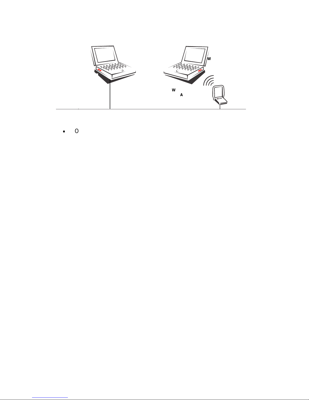
What Components Do I Need?
To set up a wireless network you need at least one access point and at least
one wireless client workstation (a computer with a wireless Ethernet client
device installed).
A Intel Wireless Ethernet Access Point
x
Intel Wireless Ethernet Access Point model APWE
x
Access Point power supply and power supply cord
Note: On the bottom of the Access Point there is a 12-character
alphanumeric string called the “MAC” or hardware address. This
address identifies the Acces s Point. Make a note of this address for
each Access Points you plan to install.
An Existing Wired Network and Wired Workstation
x
A fully installed and operational wired Ethernet local area network
(LAN) running at 10 or 100 Mbps.
x
A shielded RJ-45 cable to connect the Access Point to the wired
LAN
x
DHCP or BOOTP server support on the network (optional)—if your
network supports DHCP or BOOTP, a network IP address will be
assigned automatically to the Access Point when it is connected to
the network and powered on. Without a DHCP or BOOTP server,
you will have to manually input a network IP address for the Access
Point using the “KickStart” software supplied with the Access Point.
x
An accessible RJ-45 wall or hub connection through which to
connect the Access Point to the wired LAN
x
An accessible wall outlet or other AC power source for connection
of the Access Point power supply
x
A workstation connected to the wired LAN and equipped with a CDROM drive, running Microsoft Windows 2000, 98SE, ME, 95 OSR2,
or NT, with one of the following web browsers installed: Microsoft
Internet Explore 5.0 or 5.5, Netscape Navigator 4.78 or 6.0. This
workstation is required for configuration of the Access Point and
must be connected to the same Ethernet segment or subnet as the
Access Point being installed. (The Access Point cannot be
configured from a wireless workstation.)
Page 8
8
Wireless Client Stations
x
One or more client workstations equipped with an 802.11bcompliant wireless client adapter. Client workstations must have the
same network configuration and WEP security key (if used) as the
Access Points they will connect to. (See the documentation
supplied with the client adapter for installation and configuration
instructions.)
Wired LAN workstation
for Access Point
management
Wireless Ethernet
Access Point
W
ireless workstation
w
ith client adapter (PC
C
ard)
W
ired LAN
Page 9
9
How Do I Install and Power On the Access Point?
x
Make a note of the 12-character MAC address on the bottom of the
Access Point before attaching the Access Point to a wall or other
surface. You will need this information during configuration (you can
configure the Access Point before permanently attaching it, as long as
it’s connected to the same network segment during and after
configuration).
x
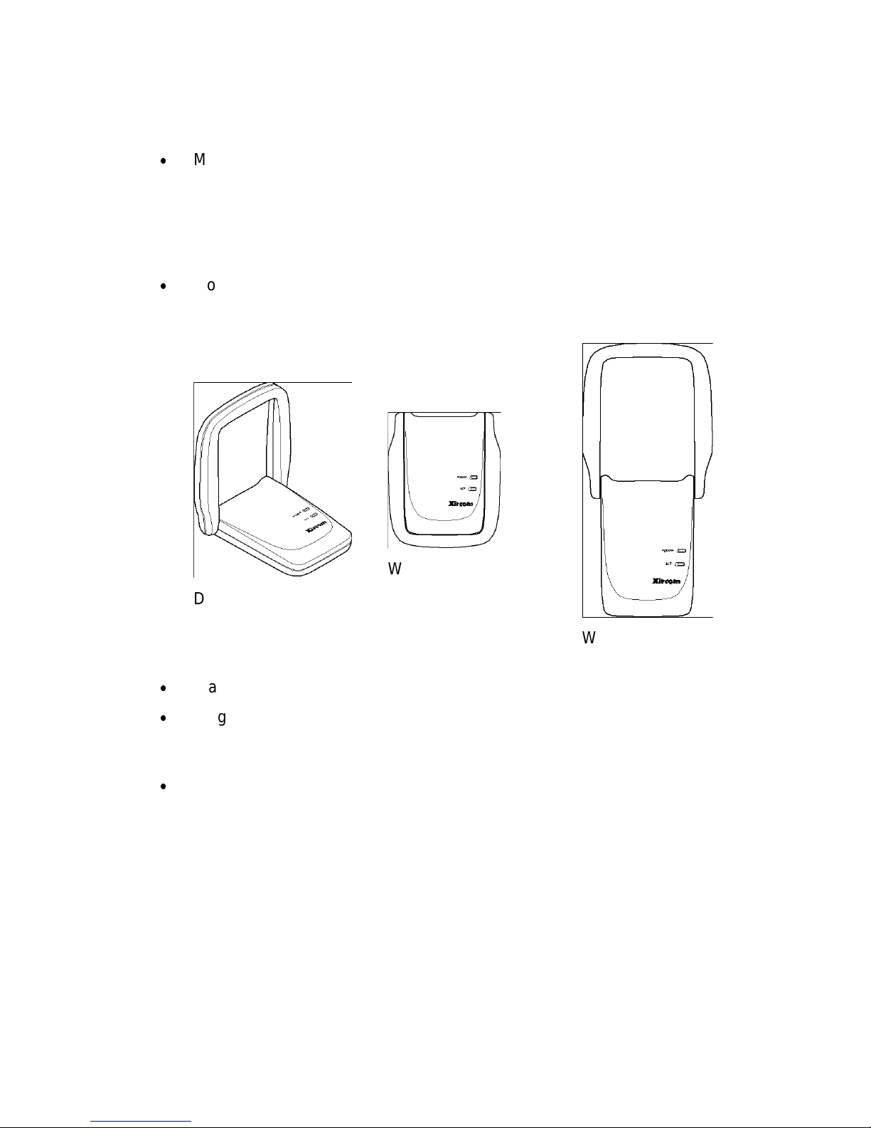
Mount the Access Point on a desk or wall, using the mounting screws
and anchors supplied (a mounting template is provided at the end of this
manual), in the location defined in Step 1.
Desk location, antenna
at 90 degree angle
Wall mounted, lowered
antenna
Wall mounted, antenna
fully raised vertically
x
Place the antenna in vertical position for best radio performance.
x
Plug the power cord into the Access Point power supply and into a wall
outlet or other source of power. Plug the thin power supply cable into the
round connector to the right of the RJ-45 on the Access Point.
x
When the Access Point is powered on, the POWER LED will illuminate
green and the wireless Activity (ACT) LED will blink, indicating that the
Access Point is searching for a wireless client.
Page 10
10
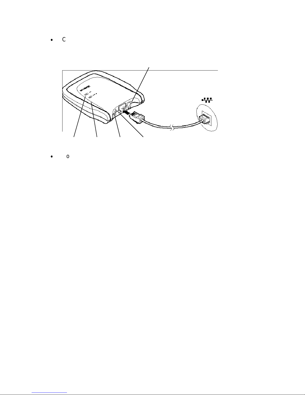
x
Connect a shielded RJ-45 cable to the Access Point and to an Ethernet
hub or wall connection. The LINK indicator next to the RJ-45 connector
will light.
Power supply connector
Wireless
Activity
Power Wired
Link
Reset button
pinhole
Ethernet
connection
x
Continue with Step 3. Set or Change IP Address
Step 3. Set or Change IP Address
How do I configure the Access Point?
Two types of configuration software are supplied with the Intel Wireless
Ethernet Access Point.
KickStart - a utility program that must be used for preliminary configuration
of the Access Point, in particular to verify or configure the IP settings
required for communication on the network. Install KickStart from the Intel
Wireless Ethernet CD-ROM onto a computer connected to the same wired
network and same network segment and subnet as the Access Point, and
use it as described below. See Installing KickStart and the following
headings.
AP Configurator – a browser-based utility that resides on the Access Point
itself. This utility’s web interface can be accessed from a computer
connected to the Access Point, using a web browser such as Microsoft
Internet Explorer version 5.0 or 5.5 or Netscape Navigator version 4.78 or
6.0. Use the web address prefix http:// followed by the IP address of the
Access Point to display the AP Configurator. See Step 4: Advanced
Configuration. The browser and web interface will automatically open when
you click Finish in KickStart.
Page 11

11
How do I connect a computer to configure the Access
Point?
To install and run KickStart and to use the browser-based AP Configurator,
you will need a computer connected to the Access Point. There are two ways
to connect this computer:
x
If the Access Point and computer are connected to the same hub or to
Ethernet connections on the same network segment, use standard RJ45 cables for the connections.
x
If the Access Point and computer are connected directly, not through a
hub or network, use a “crossover” or “crosswire” cable to connect them.
Setting the IP address of the Access Point
The most important step after connecting the hardware and powering up the
Access Point is to assign an IP address to the Access Point. This address
identifies the Access Point on the wired LAN to which it is connected. The
Access Point must be on the same subnet mask as the wired network.
There are three ways to configure the IP address using the KickStart utility.
This utility must be run on a wired workstation connected to the same
network segment as the Access Point.
Ways of
setting the
IP address
When to use
Automatic If the wired LAN to which the Access Point is connected has
a DHCP server, an appropriate IP address will be assigned
to the Access Point. In this case, when you run KickStart and
scan for Access Points, the assigned IP address will be
displayed. Click Next in KickStart and Finish. This will start
your default web browser and display the AP Configurator
that will allow you to configure security and other advanced
options.
Auto IP
(APIPA)
If there is no DHCP server on the wired LAN, KickStart will
tentatively assign an IP address based on the IP address of
the computer on which KickStart is running. Consult your
network administrator to verify that the address assigned is
available and correct. Use KickStart to change this address if
necessary.
Manual If there is no DHCP server on the wired LAN, and the IP
address assigned by KickStart is not available, use KickStart
to manually enter an IP address supplied by your network
administrator.
Page 12

12
Installing KickStart
The KickStart application can be found on the Intel CD-ROM.
You can install KickStart on a PC connected to the network to which the
Access Point will be connected, on a PC directly connected to a hub to which
the Access Point is also connected, or on a PC connected directly to the
Access Point with a “crossover” RJ-45 cable.
x
Insert the Intel Wireless Ethernet Access Point CD-ROM into the CDROM drive of the computer you will use to configure the Access Point..
x
User Start/Run or Windows Explorer to run SETUP.EXE from the folder
\KickStart on the Intel CD-ROM.
x
Follow InstallShield Wizard onscreen instructions to complete the
installation.
x
On the Setup Complete screen, check the box next to the phrase "Yes,
launch the program file" and click Finish.
x
The KickStart Welcome screen will display. Click Next. (You can also
launch KickStart by double-clicking the KickStart icon, by selecting Start,
Programs, Intel, KickStart, or by selecting Start, Run, and typing
“kickstart/a”)
x
The Select Wireless Ethernet Device screen will appear. KickStart will
search for all Access Points within range, whether they have been
configured to work with the Access Point or not. If the device you want
to manage does not appear, click Rescan.
The Select Wireless Ethernet Device screen
The columns on the Select Wireless Ethernet Device screen contain the
following information on the wireless devices found.
Column Description
MAC
address
Every APWE on the same network has a unique MAC address
that identifies it. This hardware address ca nnot be cha nged .
IP
address
All devices on a TCP/IP-based network must have an IP address
that identifies it to other devices on the same network. This
address can be set automatically by a DHCP server as soon as
the Access Point is connected to the network, provisionally by
the KickStart auto IP feature when KickStart is run (using the IP
address of the computer on which KickStart is being run), or
manually using the KickStart utility.
Page 13

13
Column Description
SSID The SSID or Service Set ID is also known as Network ID or
network name. It is the name of your wireless network. Only
clients and Access Points that share the same SSID are able to
communicate with each other. The factory default SSID of the
Access Point is “default.”
Location This is an optional text field. You can change its content via the
web interface. Content of this field does not affect operation of
the Access Point.
Contact This is an optional text field. You can change its content via the
web interface. Content of this field does not affect operation of
the Access Point.
Scanning and rescanning for devices
x
If the Access Point you want to manage is in the list, select it, and click
Next. If a DHCP server on the network has already assigned a valid IP
address, click Next and Finish. Otherwise, the Change IP Settings
screen will appear.
x
If you click the Rescan button, KickStart will search for Access Points
again. If the device that you want to configure does not appear on the
list, even after clicking the Rescan button, reset the Access Point by
pressing and holding the Reset button on the Access Point with the end
of a paperclip for 15 seconds, then run KickStart again. Allow several
minutes for the software to detect recently reset or powered Access
Points. Restarting the computer will allow recently reset Access Points
to be discovered.
The Change IP Settings Screen
On this screen you can select dynamic or static IP address settings.
KickStart attempts to assign an IP address based on the address of the
computer on which KickStart is running. You may see a message indicating
that KickStart was unsuccessful.
x
Select "Use dynamic IP settings (recommended)" when installing the
Access Point on a network with a DHCP server. Important: Do not
select this option unless you are sure the network the Access Point is on
has working DHCP support. If you select "Use dynamic IP settings" on a
network without a DHCP server, you will be unable to configure the
Access Point without resetting it to factory default values and starting
over with KickStart.
x
Select "Use static IP settings" when you want to configure the IP
address settings manually. Choose this option on networks without
automated DHCP support for IP address settings. Click the Next button.
Page 14

14
x
If you selected the option "Use dynamic IP settings" you will continue to
the screen Changing IP Settings.
x
If you selected the option "Use static IP settings" you will continue to the
screen Set IP Address of Wireless Device.
Static IP address settings
When you select the option Use static IP settings on the Change IP Settings
screen, you can manually insert the IP address and Subnet mask, or you can
click Suggest to let the system find the IP address settings.
Suggest IP settings
KickStart will look on the network for a free IP address. Although this will
normally be successful, there is a chance that a conflict will occur later. For
example, if a computer using the suggested IP address is currently turned off
or not connected to the network, a conflict will occur when that computer
comes back online. In this case you will have to reset the Access Point and
run KickStart again and reconfigure the IP address in accordance with
information provided by your network administrator.
Once the IP address is set manually or otherwise, click Next to continue to
the next screen. The screen Set Gateway of Wireless Device appears. In this
screen you can install the Gateway address of the wireless device. Setting a
Gateway is optional. The Gateway address must be on the same network
segment as the IP Address. For example, if the IP address is 192.168.2.33,
the gateway should be 192.168.2.1. Note: If you leave the gateway field
blank, the gateway will be set to xxx.xxx.xxx.1 where the x’s represent the
network segment address.
Click Next to continue to the next screen, Changing IP Settings.
Changing IP Settings
KickStart will install the proper IP address settings for the device.
If the IP address cannot be set, a warning is given. With the Back button you
can return to Change IP Settings where you can select another method for
configuring the IP address settings.
If the IP address configuration was successful, the Next button becomes
active. Click the Next button, and the screen Ready to start appears. Click
Finish.
Ready to start the browser interface
When you click Finish, KickStart will launch the default web browser on your
computer and open the Settings Summary page for the Access Point you
have chosen. Then KickStart quits. You must have one of the following
Page 15

15
browser versions installed: Microsoft Internet Explorer versions 5.0 or 5.5 or
Netscape Navigator versions 4.78 and 6.0.
When you use KickStart to find an Access Point with the correct IP address
settings, KickStart will automatically launch the AP Configurator tool in your
default browser.
Important: The browser-based AP Configurator cannot be used to change
IP address settings. If you want to change IP settings, you have to rerun
KickStart, go to the screen Change IP Settings and make the changes there.
You may also have to reset the Access Point before running KickStart to
change the IP settings.
Step 4: Advanced Configuration
Starting the browser Interface
When there is no DHCP server in your network, you can assign an IP
address to the Access Point and start up the browser interface with the
KickStart ap plication.
The KickStart application is needed when:
x
You start the Access Point for the first time, or
x
You have reset the Access Point to factory defaults (see Resetting to
the default factory settings) and must configure the IP address settings
again.
x
You need to change the IP address settings
Browser interface is launched
Once the KickStart application has finished and the Access Point is available
for configuration on the network, the browser interface application is
launched in your default web browser. Important: It is strongly
recommended that you bookmark the Access Point location in your browser.
If it is not bookmarked, you will have to type in the Access Point IP address
each time you wish to access the AP Configurator.
You can now edit the settings for the Access Point.
Launching browser interface manually
If you know the IP address of an Access Point, you can launch the browser
interface in a web browser for editing.
1. Open a web browser (Microsoft Internet Explorer versions 5.0 or 5.5 or
Netscape Navigator versions 4.78 and 6.0)
Page 16

16
2. Insert the web address of the Access Point on the address bar as
follows:
http://IP address of the Access Point/
3. Bookmark the web address of the Access Point browser interface.
Contents of web interface
The browser interface application contains the following topics:
Page Description
Settings Summary On this page you will find an overview of the
current settings.
Wireless Settings The settings of the wireless device are displayed
here, and you can edit some of these settings.
Security against
unauthorized network
access
On this page you can allow or deny access to the
Access Point by wireless client workstations by
entering the MAC address of the client.
Security against
eavesdropping
On this page you can install security methods to
prevent eavesdropping on the connection to the
Access Point.
Security against
unauthorized
configuration
On this page you can manage the Write
Community String for the Access Point and lock
the management of the Access Point.
Identity Here the identity data of the Access Point are
displayed, and you can edit some of these data.
IP Settings The IP, subnet, and gateway addresses of the
Access Point are displayed here.
Settings Summary
To display the web page Settings Summary, click the Settings Summary
button in the left panel.
You cannot change any of the settings in this page. The table below contains
references to the pages where these settings can be changed.
Setting Refer to browser interface page
SSID Wireless Settings.
IP address IP address settings (to change these settings you will
need run the KickStart application)
Access Control Security against unauthorized network access
Page 17

17
Eavesdropping
mode
Security against eavesdropping
Wireless Settings
On this page you can install items such as the identification of the device and
the radio channel.
To display the web page Wireless Settings, click the Wireless Settings
button.
The table below contains the descriptions of the options on this page.
Option Description
SSID This is the Service Set ID. Only Access Points and clients
that share the same SSID are able to communicate with
each other.
Radio
Channel
This is the channel that the Access Point uses to transmit
and receive information.
The channel that you select here is restricted to the channels
that can be used within your Regulatory domain.
Regulatory
Domain
The Regulatory domain is displayed here. Every country has
a Regulatory Domain defining radio channels that can be
used to transmit and receive signals. This setting is a factory
default that cannot be changed.
Security Against Unauthorized Network Access
To protect your network against unauthorized network access you can create
an Access Control List (ACL).
To display the web page Security Against Unauthorized Network Access,
click the button with that name.
You can choose to allow access to all clients or deny access to all clients,
and then create a list of exceptions for either option.
The changes to the Access Control List on this page are accepted when you
click the OK button.
All clients are
accepted
When you select this option, you allow access to all PC
Cards, except for ones that you specify in the Exception list.
This option can be useful if you do not want to keep track of
all PC Cards but you do know some PC Cards that need to
be denied access because, for example, they were stolen.
All clients are
denied
When you select this option, you deny access to all PC
Cards except the ones you specify in the Exception List.
Page 18

18
After you have decided whether to allow access to all clients or deny all
clients, you can create an Exception List. See instructions below on how to
add or delete a client.
Note. The title of the Exceptions list shows
x
Exception List (Denied Clients) when the exceptions are applicable to
the option Allow access to all clients.
x
Exception List (Accepted Clients) when the exceptions are applicable
to the option Deny access to all clients.
To add a client to the exception list
Follow these steps to add a client to the exception list:
1. Click Add client. A separate window opens
If you selected Allow access to all clients, type the MAC address of the
client to be denied access.
If you selected Deny access to all clients, type the MAC address of the
client to be allowed access.
2. Click OK. The client is now added to the exception list.
To delete a client from the exception list
Follow these steps to delete a client from the exception list:
1. Click Delete clients. A separate window opens displaying the exception
list .
2. Select the MAC address of each client to be removed from the list.
3. Click OK. The exception list is updated.
Security Against Eavesdropping
On this page you can install the encryption methods that secure the data
flow from and to the Access Point.
To display the web page Security Against Eavesdropping, click the button
with that name.
You can use different authentication methods. The table below describes the
available methods.
Option Description
IEEE
Authentication
Select this method to allow clients to access to the
Access Point either without security (Open Systems)
or with a Wired Equivalent Privacy (WEP) security
method.
Page 19

19
Open System (No
authentication)
When you select this option, clients have access
without a password (for example, a WEP key).
WEP Change
Settings
When you select this option, you can activate the
WEP security method.
The dialog box Enter the WEP Settings appears.
Change WEP Key
When you have selected the option Change WEP Settings, the Enter the
WEP Settings window appears. Follow the instructions below to change the
WEP ke y:
1. Select the WEP method: 40-bit or 128-bit.
2. Enter a WEP key:
WEP 40-bits: the key must contain exactly 10 hexadecimal characters
(see below), no more and no fewer, with no spaces
WEP 128-bits: the key must contain exactly 26 hexadecimal characters
(see below), no more and no fewer, with no spaces
Note: Hexadecimal characters used for the WEP key can be any 10-
character or 26-character combination of the following numeric or
alphabetical characters. Use lower-case alphabetical characters only.
0 through 9
a through f
3. Click OK.
Security Against Unauthorized Configuration
On this page you can set or change a password, the “Write Community
String” that is required to make changes to the Access Point. You can also
Lock the Access Point.
To display the web page Security Against Unauthorized Configuration, click
the button with that name.
x
Change Password.
Click Change Password and a window opens in which you can enter a
password that is required to edit the settings of the Access Point with the
web Interface.
x
Lock Access Point.
Click Lock Access Point to lock it.
Page 20

20
A warning appears “Are you sure to lock the Access Point? This will
immediately prevent making configuration changes. You will still be able to
view the current settings.”
Click OK to lock the Access Point.
No more configuration changes to the Access Point are allowed.
To unlock the Access Point, insert the end of an unbent paper clip briefly (1-
2 seconds) into the Reset button on the end of the Access Point. See How to
Unlock and Reset the Access Point for details.
Identity
This page contains physical information on the Access Point.
To display the web page Identity, click the button with that name.
Option Description
Location This is a text field in which you can enter the location of the
Access Point (“Room 412”). You can put any text into this field;
the text has no influence on how the Access Point functions.
Contact This is a text field in which you can enter, for example, the
name of the systems administrator responsible for the Access
Point (“admin@domain.com”). You can put any text into this
field; the text has no influence on how the Access Point
functions.
MAC
address
The MAC address is displayed here.
Access
Point Type
Information on your type of Access Point is displayed here.
Firmware
Version
Here the version of the Access Point firmware is displayed.
When you have filled in or changed your data:
x
Click Cancel to discard the changes.
x
Click Apply to apply the changes to the Access Point.
IP Settings
To display the web page IP Settings, click the button with that name.
On this web page the following IP address settings are displayed:
x
IP Address
Page 21

21
x
Subnet mask
x
Gateway
It is not possible to change these addresses from within the web Interface.
If you want to change the IP address settings of an Access Point already
configured with correct IP address settings, run the KickStart utility and
change the settings manually.
Troubleshooting
If KickStart does not find the Access Point you are
looking for
There are several possible causes depending on the way the Access Point is
connected to the network.
Power supply connector
Wireless
Activity
Power Wired
Link
Reset button
pinhole
Ethernet
connection
Troubleshooting the wireless connection of an Access Point
Possible cause Solution
Is the Access Point
powered and
connected to the
network?
Verify that the power cord is properly connected.
Verify that the network connection is reliable .
Is the Access Point is
in range of the wireless
Ethernet card on your
client computer?
Check the radio signal LED.
See Specifications to check for possible problems
with respect to range.
Page 22

22
Is there a network
connection?
Check the network LED.
The Access Point may take up to a minute to find
an IP address it can use if Auto IP is used to
assign an IP address.
Client cannot make
connection
A wireless client cannot conne ct to the Access
Point.
Verify that the client workstation is on the same
network segment and is using the same SSID and
WEP configuration. Be sure the client has been
granted access to the Access Point on the
Security Against Unauthorized Network Access
screen.
If the wireless client still cannot connect to the
Access Point and other troubleshooting measures
have been completed, see the documentation for
the wireless client for additional information.
Problems on the wired side
Verify that you are using the correct type of cable and that it is securely
connected.
Troubleshooting the wired connection of an Access Point
Possible cause Solution
Has the proper cable
been used?
x
If the Access Point is connected to a hub, a
normal (not crosswired) cable must be used.
x
If the Access Point is connected directly to a
computer, a crosswired cable must be used.
How to Unlock or Reset the Access Point Using the
Pinhole Reset Button
The Access Point can be locked using the Security Against Unauthorized
Configuration screen in the browser-based AP Configurator. To unlock it,
follow the instructions below.
Use the recessed Reset button to the left of the RJ-45 connector at the end
of the Wireless Ethernet Access Point to unlock the Access Point for SNMP
monitoring or to perform three levels of reset, depending on how long the
button is depressed.
To unlock the Access Point or reset it, unbend a paper clip, insert one end
into the Reset button pinhole and push in gently. Continue to push in the
Page 23

23
button for the approximate length of time below to trigger the events
described:
1-2 seconds
Unlocks the Access Point to make it available for SNMP
network management, after having locked it with the Lock
button on the WLAN Security tab in Access Point Manager,
or the Lock Access Point button on the Security Against
Unauthorized Configuration in the browser-based interface.
10-15
seconds
Resets the Access Point to factory settings (hard reset) for
IP address, network ID, security level and encryption key.
The ACTIVITY light on the top of the unit will cycle on and
then turn off until the reset button is released. After this type
of reset, KickStart must be run again to reconfigure the
Access Point IP address and other settings.
15 seconds
or more
Resets the connection to the wired LAN. The ACTivity light
on the top of the unit will cycle on, then turn off until the
reset button is released. The LINK light above the Reset
pinhole will cycle off and on after the reset button is
released.
Page 24

24
Specifications
Model
Intel Wireless Ethernet
Access Point (APWE)
System Requirements
Microsoft Windows 2000, 98SE,
ME, 95 OSR2, or NT; Microsoft
Internet Explorer 5.0 or 5.5 or
Netscape Navigator 4.78 or 6.0.
IEEE 802.11b compliant Wireless
Ethernet Adapters are required for
network access.
Data Rates Supported
1, 2, 5.5 and 11 Mbps with
auto fallback (autorate setting
required on Access Point and
network devices)
Modulation
11 Mbps and 5.5 Mbps: CCK;
2 Mbps: DQPSK; 1 Mbps: DBPSK
Network Standard
IEEE 802.11b wireless LAN, IEEE
802.3 wired LAN
Network Interface
10/100 Base-T autosensing (RJ-45
connector)
Network Protocol
TCP/IP, IPX, NetBEUI, SNMP
Management Utility
Intel browser-based Access Point
Configurator to manage access
point and client access control
Security
Supports 40-bit and 128-bit Wired
Equivalent Privacy (WEP)
encryption
Frequency Band
2400-2483.5 MHz
Wireless Medium
Direct Sequence Spread Spectrum
(DSSS)
Media Access Protocol
Carrier Sense Multiple Access with
Collision Avoidance (CSMA/CA)
Operating Channels
US, Canada: 11 channels;
Most European Countries: 13
channels; Japan: 14 channels;
France 4 channels
Simultaneous Channels
Three non-overlapping
Roaming
IEEE 802.11b compliant
Supported Users
Up to 64 simultaneous users
Typical Range at 11 Mbps
Up to 300 ft (90 m) in open
environments and 100 ft (30 m) in
office environments
Typical Range at 1 Mbps
Up to 1000 ft (300 m) in open
environments and 300 ft (90 m) in
office environments
Certifications
FCC Class B, FCC Part 15.247,
Canada ICES Class B, CE, UL,
CSA. Call for other information
outside the USA
Power Supply
5V DC External
Antenna
Dual diversity
Page 25

25
Regulatory Notices
This section provides the following notices:
x
FCC Part 15 Declaration of Conformity and Regulations
x
Mexico Domain and Channel Requirements
x
European Community CE Mark Declaration of Conformity
x
Safety Notices
FCC Regulations Part 15 Declaration of Conformity
(DoC)
Xircom, Inc., an Intel company, declares that the equipment described in this
document is within the requirements of the Code of Federal Regulations
listed below:
Title 47 Part 15, Subpart B, Class B for a digital device.
This declaration is based upon the compliance of the Intel Wireless Ethernet
Access Point model APWE1100 to the above standards. Xircom has
determined that model APWE1100 has been shown to comply with the
applicable technical standards if no unauthorized change is made in the
equipment and if the equipment is properly maintained and operated.
These units are identical to the units tested and found acceptable with the
applicable standards. Records maintained by Xircom continue to reflect that
units being produced under this Declaration of Conformity, within the
variation that can be expected due to quantity production and tested on a
statistical basis, continue to comply with the applicable technical standards.
Responsible Party: R.W. Bass, Vice President and General Manager,
Xircom, Inc., an Intel company, 2300 Corporate Center Drive, Thousand
Oaks, California
FCC Rules and Regulations - Part 15
This device complies with Part 15 of the FCC rules. Operation is subject to
the following two conditions:
1
This device may not cause harmful interference and,
2
This device must accept any interference received, including
interference that may cause undesired operation.
This equipment has been tested and found to comply with the limits for a
Class B digital device pursuant to Part 15 of the FCC rules. These limits are
designed to provide reasonable protection against harmful interference in a
residential installation. This equipment generates, uses, and can radiate
radio frequency energy and, if not installed and used in accordance with the
instructions, may cause harmful interference to radio communications.
However, there is no guarantee that interference will not occur in a particular
installation. If this equipment does cause harmful interference to radio or
television reception, which can be determined by turning the equipment off
and on, the user is encouraged to try to correct the interference by one or
more of the following measures:
Page 26

26
x
Reorient or relocate the receiving antenna.
x
Increase the separation between the equipment and the receiver.
x
Connect the equipment into an outlet on a circuit different from that to
which the receiver is connected.
x
Consult the dealer or an experienced radio/TV technician for help.
Changes or modifications not expressly approved by the manufacturer or
registrant of this equipment can void your authority to operate this equipment
under Federal Communications Commission rules.
In order to maintain compliance with FCC regulations, standard shielded
network cables must be used with this equipment. Operation with nonapproved equipment or non-standard cables may result in interference to
radio and TV reception.
Mexico Domain and Channel Requirements
For operation in Mexico, use the North American or ANZ Regulatory Domain.
Allowable channel identifier settings for Mexico are 10 (2457 MHz) and 11
(2462) only.
European Community - CE Mark
Declaration of Conformity
Xircom, Inc. declares that the equipment described in this document is in
conformance with the requirements of the European Council Directive listed
below:
73/23/EEC Low Voltage Directive with Amendment 93/68/EEC
89/336/EEC EMC Directive with Amendments 92/31/EEC and 93/68/EEC
1999/5/EC Radio and Telecommunications Terminal Equipment Directive
This declaration is based upon compliance of the product to the following
standards:
x
ETS 300 328/A1 (1997-07, Edition 2) Radio Equipment and Systems
(RES); wideband transmission systems; technical characteristics and
test conditions for data transmission equipment operating in the 2.4 GHz
ISM band and using spread spectrum modulation techniques
x
ETS 300 826 (1997-11, Edition 1) Electromagnetic compatibility and
radio spectrum matters (ERM); electromag neti c com pati bil ity (EM C )
standard for 2.4 GHz wideband transmission systems and high
performance radio local area network (HIPERLAN) equipment
x
EN 60950 1992 2nd Edition (A1 - A4, A11) Safety of Information
Technology Equipment, Including Electrical Business Equipment
Warning: Due to the fact that the frequencies used by 802.11b are not yet
harmonized, certain Xircom 802.11b products are designed for use only in
specific countries, and may not function properly in a country other than the
Page 27

27
country of designated use. As a user of these products, you are responsible
for ensuring that the products are used only in the countries for which they
were intended.
The following bandwidth restrictions are in effect:
France 2446.5 - 2483.5 MHZ
Other EU countries 2400 - 2483.5 MHZ
Product Description: Wireless Ethernet Access Point model APWE1100
Responsible Party:
R.W. Bass, Vice President and General Manager, Xircom, an Intel company,
Veldkant 31, 2550 Kontich, Belgium.
Safety Notices
The FCC with its action in ET Docket 96-8 has adopted a safety standard for
human exposure to radio frequency (RF) electromagnetic energy emitted by
FCC certified equipment. The Wireless Ethernet Access Point products meet
the uncontrolled environmental limits found in OET-65 and ANSI C95.1,
1991. Proper operation of this radio according to the instructions found in this
manual will result in exposure substantially below the FCC’s recommended
limits.
Danger: Do not operate a portable transmitter near unshielded blasting caps
or in an explosive environment unless it is a type especially qualified for such
use.
Caution: Do not touch or move antenna while the unit is transmitting or
receiving.
Caution: Do not hold any component containing the radio so that the
antenna is very close or touching any exposed parts of the body, especially
the face or eyes, while transmitting.
Caution: Do not operate radio or attempt to transmit data unless the
antenna is connected; if the antenna is not connec ted, the ra dio may be
damaged.
Antenna
Warning for Users of Laptop Connected to a Wireless Network To
comply with the FCC RF exposure limits, it is recommended when using a
laptop with the integrated antenna, that the antenna should not be positioned
closer than 5 cm (two inches) from your body or nearby persons for
extended periods of time while it is transmitting (or operating). If the antenna
is positioned less than 5 cm (two inches) from the user, it is recommended
that the user limit exposure time.
Other Devices in the Wireless Network Refer to the documentation
supplied with wireless Ethernet adapters or other devices in the wireless
network.
Caution: Regulations of the FCC and FAA prohibit airborne operation of
radio-frequency wireless devices because their signals could interfere with
critical aircraft instruments.
Page 28

28
Limited Lifetime Warranty
Warranties
As the original purchaser, you receive these warranties from Xircom, Inc., a
wholly owned subsidiary of Intel Corporation:
Hardware
Your Intel Wireless Ethernet Access Point (collectively, “Products”) will be
free from defects in material and workmanship and will perform in substantial
compliance with your user documentation accompanying the Products for as
long as you own and properly care for and use the Products.
Software
Software accompanying these Products (including driver, utility software,
etc.) and the media containing the software are warranted to perform in
substantial compliance with the specifications contained in your user
documentation for two years from your purchase date. Our warranty does
not cover or provide you with rights to upgrades or updates.
You are responsible for your choice of applications programs or related
reference materials. Given the wide range of third party hardware and
applications software products you might use our software with, you
understand that Xircom does not warrant the compatibility or the
uninterrupted or error free operation of our software. Upon our confirmation
of a covered defect or failure, at our option we will repair or replace the
affected item or will refund your purchase price if repair or replacement is not
possible or practical. At our option, replacement products or repaired items
may be a new, refurbished, or functionally equivalent item. Our warranty on
items serviced under warranty will be lifetime for hardware and, for software,
90 days from return to you of software media or the remainder of the original
warranty, whichever is longer. Repair, replacement, or refund are the
exclusive remedies available to you from Xircom for products and software.
Your Obligations
Your warranty rights will be honored provided you
1. Read and follow your user documentation for assembly, installation,
setup, software setup, and operating guidelines.
2. Use the Products and software only in suitable physical or operating
environments as described in your user documentation and for purposes
for which the Products and software are intended.
Warranty Service
If you think there is a problem or defect with your purchased item, your point
of contact will be:
In the U.S.A.
Intel’s Technical Support department at (916) 377-7000.
Page 29

29
Outside the U.S.A.
Contact your local Xircom supplier or Xircom regional office.
Your Xircom contact will discuss your problem to confirm the defect. If
warranty or return service is needed, you’ll receive a Return Material
Authorization (RMA) number. Replacement Product will be shipped when the
original Product has been received by Xircom.
Ship your return Product prepaid, with the RMA number clearly visible on the
outside of the shipping package, to:
From the U.S.A.
Xircom Service Department
2101 Corporate Center Drive
Thousand Oaks, CA 91320-1422
From outside the U.S.A.
Contact your local Xircom supplier or Xircom regional
center for shipping instructions.
Returned Products may need to include, if requested by Xircom, all other
components from your original package, including the Product and any
cables, connectors, software media, and user documentation. Be sure to
enclose a copy of your purchase receipt or other proof of purchase
confirming that you are the original purchaser.
Limitations
Our warranty is subject to the following limitations:
x
We do not cover or accept liability for any injury, damage, breakage or
failure caused by misuse, abuse, acts of Nature, accidents (e.g.,
dropping the Products or software media), failure to follow instructions
and procedures contained in the user documentation, electrical
mishaps, causes beyond our control, or claims by other than the original
purchaser.
x
We will not honor, and will consider our warranty voided, if there has
been any (1) tampering with the Product’s external label or serial
number, (2) attempt to open the Product’s case, (3) modification or
alteration of any component, housing, connector, or other physical
attribute of the Product, or (4) attempted or actual repair by anyone
other than an authorized Xircom technician.
Disclaimer
THIS LIMITED WARRANTY IS THE ONLY WARRANTY WE MAKE FOR
THE PRODUCT AND SOFTWARE. TO THE EXTENT ALLOWED BY LAW,
NO OTHER WARRANTY APPLIES, WHETHER EXPRESS, IMPLIED, OR
STATUTORY, INCLUDING ANY WARRANTY OF MERCHANTABILITY, OF
FITNESS FOR A PARTICULAR PURPOSE, OR OF NON-INFRINGEMENT.
XIRCOM WILL NOT BE LIABLE OR RESPONSIBLE FOR ANY
Page 30

30
INCIDENTAL, CONSEQUENTIAL, OR SPECIAL DAMAGES (e.g., LOST
PROFITS, LOSS OF OR DAMAGE TO ANY COMPUTER EQUIPMENT OR
RELATED DATA).
Additional Rights
Some states or countries do not allow exclusion or limitation of incidental or
consequential damages, or limitations on the length of an implied warranty,
so the above limitations or exclusions may not apply to you. Our warranty
gives you specific legal rights, and you may also have other rights which vary
from state to state or country to country.
International Notice
Due to differing national regulations and approval requirements, certain
Xircom products are designed for use only in specific countries, and may not
function properly in a country other than the country of desig nated us e. As a
user of these products, you are responsible for ensuring that the products
are used only in the countries for which they were intended.
Unauthorized Applications
Xircom’s products are not designed or authorized for use as a component in
any life support, life safety, or other comparable application. Our products
should not be used in any application where the failure or faulty performance
of the product might create a risk of personal injury or death. Buyer assumes
all risk of loss, damage or injury alleged to arise from the failure or faulty
performance of a Xircom product in any unauthorized application. Buyer
agrees to indemnify and hold harmless Xircom, and its officers, directors,
employees, agents, representatives, and sales partners, from and against
any and all claims, costs, damages , loss es and expenses (including
reasonable attorney fees) which arise from or are alleged to have been
caused by any claim for personal injury or death connected with Buyer’s use
of a Xircom product in any unauthorized application, including claims which
allege that Xircom has been negligent in connection with the design or
manufacture of the product.
Page 31

31
Software License Agreement
Xircom grants you a non-exclusive license to use the copies of software
programs supplied with this product on the following terms:
You may:
1. Use the software program on any computer or network but only in
conjunction with any Xircom hardware product;
2. Permit any other individuals to use the software program either directly
or on a computer network, but only if there is no more than one user for
each Xircom hardware product in use in conjunction with such use;
3. Make only those number of backup and archival copies of the software
program in machine readable form as are essential to backup use of the
software program, provided that you reproduce all proprietary notices on
each copy.
You may not:
1. Modify, translate, reverse engineer, decompile, disassemble, create
derivative works based on, or copy (except for archival purposes) the
program or the accompanying documentation;
2. Rent, transfer, sublicense or grant any rights in the program or
accompanying documentation (including any time-sharing arrangement)
in any form to any other person without the prior written consent of
Xircom;
3. Remove any proprietary notices, labels, or marks on the program and
accompanying documentation.
Failure to comply with any of the above restrictions will terminate this license.
This is not a sale. Title and copyrights to the program and accompanying
documentation and any copies remain with Xircom, except that title to
software programs shipped by Xircom through an agreement with another
manufacturer is owned and retained by the original manufacturer, and no title
to the intellectual property contained in such programs is transferred
hereunder. The human readable code of the software program (source
code), including the source code of programs shipped by Xircom through an
agreement with another manufacturer, is not sublicensed hereunder.
U.S. Government Restricted Rights
The SOFTWARE and documentation are provided with RESTRICTED
RIGHTS. Use, duplication, or disclosure by the Government is subject to
restrictions as set forth in subparagraph (c)(1)(ii) of the Rights in Technical
Data and Computer Software clause at DFARS 252.227-7013, or
subparagraphs (c)(1) and (c)(2) of the Commercial Computer SoftwareRestricted Rights at 48 CFR52.227-19, as applicable.
Contractor/manufacturer is Xircom, Inc., a wholly owned subsidiary of Intel
Corporation, 2300 Corporate Center Drive, Thousand Oaks, CA 91320-1420.
This Agreement is governed by the laws of the State of California.
Page 32

32
Intel Access Point Wall Mount Template
Tear out this page and use the template below to position and drill the holes
required to mount the Access Point on a wall, then use the screws and
anchors supplied to attach the Access Point.
2 1/8 inch
54 mm
1/4 inch
6.4 mm
drill two places
APWE mounting kit drill pattern
 Loading...