

Page 1

Intel® 5100 Memory Controller Hub Chipset for Communications, Embedded, and Storage Applications
Thermal/Mechanical Desig n Guide
July 2008
Revision 003US
Order Number: 31867 6- 0 03US
Page 2

Legal Lines and Disclaim er s
INFORMATION IN THIS DOCUMENT IS PROVIDED IN CONNECTION WITH INTEL® PRODUCTS. NO LICENSE, EXPRESS OR IMPLIED, BY ESTOPPEL OR
OTHERWISE, TO ANY INTELLECTUAL PROPER TY RIGHTS IS GRANTED BY THIS DOCUMENT. EXCEPT AS PROVIDED IN INTEL’S TE RMS AND CON DITIONS
OF SALE FOR SUCH PRODUCTS, INTEL ASSUMES NO LIABILITY WHATSOEVER, AND INTEL DISCLAIMS ANY EXPRESS OR IMPLIED WARRANTY, RELATING
TO SALE AND/OR USE OF INTEL PRODUCTS INCLUDING LIABILITY OR WARRANTIES RELATING TO FITNESS FOR A PARTICULAR PURPOSE,
MERCHANTABILITY, OR INFRINGEMENT OF ANY PATENT, COPYRIGHT OR OTHER INTELLECTUAL PROPERTY RIGHT.
UNLESS OTHERWISE AGREED IN WRITING BY INTEL, TH E INTEL PRODUCTS ARE NO T DESIGNED NOR INTENDED FOR ANY APPLICATION IN WHICH THE
FAILURE OF THE INTEL PRODUCT COULD CREATE A SITUATION WHERE PERSONAL INJURY OR DEATH MAY OCCUR.
Intel may make changes to specifications and product descriptions at any time, without notice. Designers must not rely on the absence or characteristics
of any features or instruct ions mark ed “reserved” or “undefined .” Intel reserves these for futu re definitio n and shall ha ve no responsibility whatsoever for
conflicts or inco mp atib ilities arising from f utu re c hanges to them. The infor mation here is subject t o change without notice. Do not finalize a design with
this information.
The products described in this document may contain design defects or errors known as errata which may cause the product to deviate from published
specifications. Current characterized errata are available on request.
Contact your local Intel sales office or your distributor to obtain the latest specifications and before placing your product order.
Copies of documents which have an order number and are referenced in this document, or other Intel literature, may be obtained by calling 1-800-548-
4725, or by visiting Intel’s Web Site.
Intel processor numbers are not a measure of perfor manc e. Pro ces so r num be r s differ entiate features within each processor family, not across different
processor families. See http://www.intel.com/products/processor_number for details.
BunnyPeople, Celeron, Celeron Inside, Centrino, Centrino Inside, Centrino logo, Core Inside, FlashFile, i960, InstantIP, Intel, Intel logo, Intel386,
Intel486, IntelDX2, IntelDX4, IntelSX2, Intel Atom, Intel Atom Inside, Intel Core, Intel Inside, Intel Inside logo, Intel. Leap ahead., Intel. Leap ahead.
logo, Intel NetBurst, Intel NetMerge, Intel NetStructure, Intel SingleDriver, Intel SpeedStep, Intel StrataFlash, Intel Viiv, Intel vPro, Intel XScale,
Itanium, Itanium Inside, MCS, MMX, Oplus, OverDrive, PDCharm, Pentium, Pentium Inside, skoool, Sound Mark, The Journey Inside, Viiv Inside, vPro
Inside, VTune, Xeon, and Xeon Inside are trademarks of Intel Corporation in the U.S. and other countries.
*Other names and brands may be claimed as the property of others.
Copyright © 2008, Intel Corporati on . All righ ts reserved.
Intel® 5100 Memory Controller Hub Chipset for Communications, Embedded, and Storage Applications
TDG July 2008
2 Order Number: 318676-003US
Page 3

®
5100 MCH Chipset
Intel
Contents
1.0 Introduction..............................................................................................................6
1.1 Design Flow........................................................................................................6
1.2 Definition of Terms ..............................................................................................7
1.3 Related Documents .............................................................................................8
1.4 Thermal Simulation ................................ ........................... .... .......................... ....9
2.0 Packaging T e c h nology...............................................................................................9
2.1 Package Mechanical Requirements.......................................................................11
3.0 Thermal Specifications ............................................................................................ 12
3.1 Thermal Design Power (TDP) .............................................................................. 12
3.2 Case Temperature............................................................................................. 12
4.0 Thermal Solution Requirements...............................................................................12
4.1 Characterizing the Thermal Solution Requirement.................................................. 12
5.0 Thermal M etrology .................................................................................................. 15
5.1 MCH Case Measurement............... .... .......................... ........................... .... ......... 15
5.1.1 Supporting Test Equipment....................... .......................... .... ................. 15
5.1.2 Thermal Calibration and Controls.............................................................. 16
5.1.3 IHS Groove ........................................................................................... 16
5.1.4 Thermocouple Conditioning and Preparation............................................... 18
5.1.5 Thermocouple Attachment to IHS............................................................. 18
5.1.6 Curing Process....................................................................................... 22
5.1.7 Thermocouple Wire Management.............................................................. 23
5.2 Power Simulation Software .................. ........................... .... .......................... ......24
6.0 Reference Thermal Solutio n..................................................................................... 24
6.1 AdvancedTCA* Reference Heatsink...................................................................... 25
6.1.1 Thermal Performance .... ........................... .......................... .... ................. 25
6.1.2 Mechanical Design Envelope .................................................................... 25
6.1.3 Board-level Components Keepout Dimensions ............................................ 26
6.1.4 Torsional Clip Heatsink Thermal Solution Assembly ..................................... 26
6.1.5 Heatsink Orientation ............................................................................... 27
6.1.6 Extruded Heatsink Profiles ........................................... .......................... .. 27
6.1.7 Mechanical Interface Material...................................................................27
6.1.8 Thermal Interface Material . .......................... ........................... .... ............. 27
6.1.8.1 Effect of Pressure on TIM Performance......................................... 28
6.1.9 Heatsink Clip ......................................................................................... 28
6.1.10 Clip Retention Anchors............................................................................28
6.1.11 Reliability Guidelines............................................................................... 28
6.2 CompactPCI* Reference Heatsink ................. .... .......................... .... ..................... 29
6.2.1 Component Overview.............................................................................. 29
6.2.2 Thermal Solution Performance Characteristics ........ .... .......................... .... .. 30
7.0 Reliability Guidelines............................................................................................... 30
A Mechanical Drawings............................................................................................... 31
B Thermal Solution Component Suppliers ................................................................... 40
July 2008 TDG
Order Number: 318676-003US 3
Intel® 5100 Memory Controller Hub Chipset for Communications, Embedded, and Storage Applications
Page 4

Intel® 5100 MCH Chipset
Figures
1 Thermal Design Process ............................ .......................... .... ........................... ........ 7
2 MCH Package Dimensions (Top View)..........................................................................10
3 MCH Package Dimensions (Side View).........................................................................10
4 MCH Package Dimensions (Bottom View).....................................................................11
5 Processor Thermal Characterization Parameter Relationsh ip s ..........................................13
6 IHS Groove Dimensions.............................................................................................17
7 Orientation of Thermocouple Groove Relative to Package Pin..........................................18
8 Bending Tip of Thermocouple ......... ........................... .... .......................... ...................18
9 Securing Thermocouple Wires with Kapton Tape Prior to Attach ......................................19
10 Thermocouple Bead Placement...................................................................................20
11 Positioning Bead on Groove .......................................................................................20
12 Using 3D Micromanipulator to Secure Bead Location................ ........................... .... .......21
13 Measuring Resistance between Thermocouple and IHS ..................................................21
14 Applying Adhesive on Thermocouple Bead....................................................................22
15 Thermocouple Wire Management in Groove..................................................................23
16 Removing Excess Adhesive from IHS............................................. .......................... ....23
17 Filling Groove with Adhesive ............................................ ........................... ............... 2 4
18 Torsional Clip Heatsink Measured Thermal Performance versus Approach Velocity .............25
19 AdvancedTCA* Torsional Clip Heatsink Volumetri c Envel op e for MCH Heatsi nk ... ............... 2 6
20 Torsional Clip Heatsink Assembly................................................................................27
21 Isometric View of the CompactPCI* Reference Heatsink .... .......................... ...................29
22 CompactPCI* Reference Heatsink Thermal Performance.................................................30
23 AdvancedTCA* Heatsink Assembly Drawing .................................................................32
24 AdvancedTCA* Heatsink Drawing................................................................................33
25 AdvancedTCA* Component Keepout Zone....................................................................34
26 CompactPCI* Heatsink Assembly Drawing .............. ........................... ... .......................35
27 CompactPCI* Heatsink Drawing .. ........................... ........................... ... .......................36
28 CompactPCI* Component Keepout Zone............................ .... ........................... ...........37
29 Torsional Clip Heatsink Clip Drawing ...........................................................................38
30 TIM2 Drawing .... ... ........................... ........................... .......................... .... ............... 3 9
Tables
1 Definition of Terms .................................................................................................... 7
2 Related Documents.................................................................................................... 8
3Intel
4 Required Heatsink Thermal Performance (Ψ
5 Thermocouple Attach Support Equipment ....................................................................16
6 Honeywell* PCM45F TIM Performance as Function of Attach Pressure ..............................28
7 Reliability Guidelines.................................................................................................29
8 Reliability Requirements ............................................................................................30
9 Mechanical Drawing List ............................................................................................31
10 MCH Torsional Clip Heatsink Thermal Solution ..............................................................40
®
5100 Memory Controller Hub Chipset for Communications, Embedded, and Storage Applications
Intel
TDG July 2008
4 Order Number: 318676-003US
®
5100 Memory Controller Hub Chipset Thermal Speci fi cati ons...................... .... .......12
).............................................................15
CA
Page 5

®
5100 MCH Chipset
Intel
Revision History
Date Revision Description
Added the CompactPCI* reference solution
July 2008 003
February 2008 002 Updated the TDP
November 2007 001 Initial release
Revision Number Descriptions
Revision Associated Life Cycle Milestone Release Information
0.0 POP L3 Closure Initial Documentation - Typically Internal Only
0.1–0.4 When Needed Project Dependent - Typically Internal Only
0.5 Design Win Phase First, Required Customer Release
0.6–0.7 When Needed Project Dependent
0.7 Simulations Complete Second, Recommended Customer Release
0.8–0.9 When Needed Project Dependent
1.0 First Silicon Samples Requi r ed Customer Relea se
1.1–1.4 When Needed Project Dependent (Recommended)
1.5 Qualification Silicon Samples Project Dependent
1.6–1.9 When Needed Project Dependent
NDA - 2.0
Public - XXXXXX-001
2.1 and up When Needed Project Dependent
Note: Rows hi gh lighted in gray are required revisions.
Added Figure 26, Figure 27, and Figure 28
Updated the supplier information
Max config
First SKU Launch Requi r ed Customer Relea se - Product Launch
value to 25.7 W in Table 3
July 2008 TDG
Order Number: 318676-003US 5
Intel® 5100 Memory Controller Hub Chipset for Communications, Embedded, and Storage Applications
Page 6

1.0 Introduction
As the complexity of computer systems increases, so do the power dissipation
requirements. Care must be taken to ensure that the additional power is properly
dissipated. Typical methods to improve heat dissipation include selective use of
ducting, and/or passive heatsinks.
The goals of this document are to :
• Outline the thermal and mechanical operating limits and specifications for the
• Describe refer ence thermal solut ions that meet the spec ificati on of th e Intel
Properly designed thermal solutions provide adequate cooling to maintain the Intel
5100 MCH Chipset die temperatures at or below thermal specifications. This is
accomplished by providing a low local-ambient temperature , ensu ring adequate local
airflow, and m inimizi ng the di e to local- ambien t thermal re sistance . By main taining the
Intel
designer can ensure the proper functionality, performance, and reliability of the
chipset. Operation outside the functional limits can degrade system performance and
may cause permanent changes in the operating characteristics of the component.
The simplest and most cost effective method to improve the inherent system cooling
characteristics is through careful chassis design and placement of fans, vents, and
ducts. When additional cooling is required, component thermal solutions may be
implemented in conjunction with system thermal solutions. The size of the fan or
heatsink can be varied to balance size and space constraints with acoustic noise.
This document addresses thermal design and specifications for the Intel
Chipset components only . For thermal design information on other chipset components,
refer to the respective component datasheet. For the ICH9R, refer to the Intel
Controller Hub 9 (ICH 9) F a mily Thermal and Mechanical Design Guidelines.
®
5100 Memory Controller Hub C hi ps et (Intel® 5100 MCH Chipset )
Intel
MCH Chipset
®
5100 MCH Chipset die temperature at or below the specified limits, a system
Intel® 5100 MCH Chipset
®
5100
®
®
5100 MCH
®
I/O
Note: Unless otherwise specified, the term “MCH” refers to the Intel® 5100 MCH Chipset.
1.1 Design Flow
To develop a reliable, cost-effective thermal solution, several tools have been provided
to the system designer. Figure 1 illustrates the design process implici t to this d ocument
and the tools ap p r op r ia t e for ea ch step.
®
5100 Memory Controller Hub Chipset for Communications, Embedded, and Storage Applications
Intel
TDG July 2008
6 Order Number: 318676-003US
Page 7

®
• Package Level Thermal Models
• Thermal Model User’s Guide
Step 1: Thermal Simulation
• Reference Heatsinks
• Reference Mounting Hardware
• Vendor Contacts
Step 2: Heatsink Design
and Selection
Step 3: Thermal Validation
• Thermal Testing Software
• Thermal Test Vehicle
• User Guides
5100 MCH Chipset
Intel
Figure 1. Thermal Design Process
1.2 Definition of Terms
Table 1. Definition of Terms
July 2008 TDG
Order Number: 318676-003US 7
Term Definition
Flip Chip Ball Grid Array. A package type defined by a plastic substrate where
FC-BGA
BLT
ICH9 I/O Controller Hub 9
IHS Integrated Heat Spreader
MCH
T
case_max
T
case_min
TDP
TIM Thermal Interface Material
Ψ
CA
Ψ
CS
Ψ
SA
a die is mounted using an underfill C4 (Controlled Collapse Chip Connection)
attach style. The primary electrical interface is an array of solder balls
attached to the substrate opposite the die.
Note: The device arrives at the cus tomer with solder balls atta ch e d.
Bond line thickness. Final settled thickness of the thermal interface material
after installation of heatsink.
Memory controller hub. The chipset component that contains the processor
interface, the memory interface, the PCI Express* interface and the ESI
interface.
Maximum allowed component temperature. This temperature is measured at
the geometric center of the top of the package IHS.
Minimum allowed comp onent tem per ature. This temp era ture is meas ured at
the geometric center of the top of the package IHS.
Thermal design power. Thermal solutions should be design e d to di ssipate
this target power level. TDP is not the maximum power that the chipset can
dissipate.
Case-to-ambient thermal characterization parameter. A measure of the
thermal solution thermal performance including TIM using the thermal
design power. Defined as (T
Case-to-sink thermal characterization parameter. A measure of the TIM
thermal performance using the ther m a l desig n powe r. Defined as (T
) / TDP
T
LA
Sink-to-ambient thermal characterization parameter. A measure of heatsink
thermal performance using the ther m a l desig n powe r. Defined as (T
) / TDP
T
LA
Intel® 5100 Memory Controller Hub Chipset for Communications, Embedded, and Storage Applications
- TLA) / TDP
CASE
CASE
CASE
-
-
Page 8

1.3 Related Documents
Intel® 5100 MCH Chipset
Intel® Electronic Desi gn Kits (EDKs) provide online, real-tim e collateral updates. The
following links ta ke you to the EDK server and require you to log into Intel
Link (IBL).
• Quad-Core and Dual-Co r e Intel® Xeon® Process or 5000 Sequence with Intel®
5100 Memory Controll er Hub Chip set for C ommunica tions , Embedd ed, and Stor age
Applications
• Intel® Core™2 Duo Processors T9400 and SL9400 and Intel® 5100 Memory
Controller Hub Chipset for Commun ications and Embedd ed Applications
The reader of this specification should also be familiar with material and concepts
presented in the documents list ed in Table 2.
Table 2. Related Documents (Sheet 1 of 2)
Document Document Number/URL
BGA/OLGA Assembly Development Guide Note 1
Dual-Core Intel
Dual-Core Intel
Update
Dual-Core Intel
Mechanical Design Guidelines
Dual-Core Intel
Dual-Core Intel
Update
Dual-Core Intel
Mechanical Design Guidelines
Dual-Core Intel
Applications Thermal/Mechanical Design Guidelines
®
Intel
5000 Series Chipset Memory Controller Hub (MCH)
Thermal/Mechanical Design Guide
®
5100 Memory Controller Hub Chipset (embedded) –
Intel
External Design Specification (EDS) Addendum
®
Intel
5100 Memory Controller Hub Chipset (embedded) –
Maximum Power Application
®
Intel
5100 Memory Controller Hub Chipset Datasheet http://www.intel.com/ (318378)
®
Intel
5100 Memory Controller Hub Chipset Specification Update http://www.intel.com/ (318385)
Intel® Core™2 Duo Processor, Intel® Core™2 Solo Processor and
®
Core™2 Extreme Processor on 45-nm Process Datasheet
Intel
®
Intel
Core™2 Duo Processor, Intel® Core™2 Solo Processor and
®
Intel
Core™2 Extreme Processor on 45-nm Process
Specification Update
®
Intel
Core™2 Duo Processo rs on 45- n m pr oc es s for Embedded
Applications Thermal Design Guide
®
Intel
Core™2 Duo Processors T9400 and SL9400 and Intel®
5100 Memory Controller Hub Chipset for Communications and
Embedded Applications – Platform Design Guide
®
I/O Controller Hub 9 (ICH9) Family Datasheet http://www.intel.com/ (316972)
Intel
®
Intel
I/O Controller Hub 9 (ICH9) Family Specification Update http://www.intel.com/ (316973)
Notes:
1. Contact your Intel sales representative. Some documents may not be available at this time.
®
Xeon® Processor 5100 Series Datasheet http://www.intel.com/ (313355)
®
Xeon® Processor 5100 Series Specification
®
Xeon® Processor 5100 Series Thermal/
®
Xeon® Processor 5200 Series Datasheet http://www.intel.com/ (318590)
®
Xeon® Processor 5200 Series Specification
®
Xeon® Processor 5200 Series Thermal/
®
Xeon® Processor LV 5138 in Embedded
®
Business
http://www.intel.com/ (313356)
http://www.intel.com/ (313357)
http://www.intel.com/ (318586)
http://www.intel.com/ (318675)
http://www.intel.com/ (315225)
http://www.intel.com/ (313067)
Note 1
Note 1
http://www.intel.com/ (320120)
http://www.intel.com/ (320121)
http://www.intel.com/ (320028)
Note 1
®
5100 Memory Controller Hub Chipset for Communications, Embedded, and Storage Applications
Intel
TDG July 2008
8 Order Number: 318676-003US
Page 9

®
5100 MCH Chipset
Intel
Table 2. Related Documents (Sheet 2 of 2)
Document Document Number/URL
Intel® I/O Controller Hub 9 (ICH9) Family Thermal and
Mechanical Design Guidelines
®
Quad-Core and Dual-Core Intel
Sequence with Intel
Communications, Embedded, and Storage Applications –
Platform Design Guide
Quad-Core Intel
Quad-Core Intel
Update
Quad-Core Intel
Mechanical Design Guidelines
Quad-Core Intel
Quad-Core Intel® Xeon® Processor 5400 Series Specification
Update
Quad-Core Intel
Mechanical Design Guidelines
Quad-Core Intel
Applications Thermal and Mechanical Design Guidelines
Various system thermal design suggestions http://www.formfactors.org
Notes:
1. Contact your Intel sales representative. Some documents may not be available at this time.
®
5100 Memory Controller Hub Chipset for
®
Xeon® Processor 5300 Series Datasheet http://www.intel.com/ (315569)
®
Xeon® Processor 5300 Series Specification
®
Xeon® Processor 5300 Series Thermal/
®
Xeon® Processor 5400 Series Datasheet http://www.intel.com/ (318589)
®
Xeon® Processor 5400 Series Thermal/
®
Xeon® Processor L5318 in Embedded
Xeon® Processor 5000
http://www.intel.com/ (316974)
Note 1
http://www.intel.com/ (315338)
http://www.intel.com/ (315794)
http://www.intel.com/ (318585)
http://www.intel.com/ (318611)
http://www.intel.com/ (318474)
1.4 The rmal Simulation
Intel provides thermal simulation model s of t he Intel® 5100 MCH Chipset and
associated user’s guides to aid system designers in simulating, analyzing, and
optimizing their th ermal solutions in an integrated, system-level environment. The
models are for use with the commercially available Computational Fluid Dynamics
(CFD)-based thermal analys is tool s Flomeri cs* FLO THE RM* (ve rsion 5.1 or higher) an d
Fluent* Icepak* (v ersion 4.3. 10 or higher). Co ntact your In tel field sa les representat ive
to order the thermal models and us er’s guides.
2.0 Packaging Technology
Intel® 5100 MCH Chipset-based plat forms consist of two individual comp onents: the
®
5100 MCH Chipset and the ICH9R. The Int e l® 5100 MCH Chipset uses a 42.5
Intel
mm, 10-layer fl ip chip ball grid array (FC-BGA) pa ckage (see Figure 2, Figure 3, and
Figure 4). For information on the ICH9R package, refer to the Intel
9 (ICH9) Family Thermal and Mechanical Design Guidelines.
®
I/O Controller Hub
July 2008 TDG
Order Number: 318676-003US 9
Intel® 5100 Memory Controller Hub Chipset for Communications, Embedded, and Storage Applications
Page 10

Figure 2. MCH Package Dime nsions (Top View)
MCH
IHS
Handling
Exclusion
Area
42.5 mm.
42.5 mm.38.5 mm.
38.5 mm,
0.20
–C–
IHS
Substrate
0.435 ± 0.025 mm
See note 3
Seating Plane
2.44 ± 0.071 mm
See note 1.
Notes:
1. Primary datum -C- and seating plan are defined by the spherical crowns of the solder balls (shown before motherboard attach)
2. All dimensions and tolerances conform to ANSI Y14.5M-1994
3. BGA has a pre-SMT height of 0.5mm and post-SMT height of 0.41-0.46mm
4. Shown before motherboard attach; FCBGA has a convex (dome shaped) orientation before reflow and is expected to have a slightly concave (bowl shaped)
orientation after reflow
0.20
See note 4.
3.79 ± 0.144 mm
4.23 ± 0.146 mm
Intel® 5100 MCH Chipset
Figure 3. MCH Package Dim ensions (Side Vi ew)
®
5100 Memory Controller Hub Chipset for Communications, Embedded, and Storage Applications
Intel
TDG July 2008
10 Order Number: 318676-003US
Page 11

®
42.5 + 0.05
11 252321191715139753127293733 3531
2822 26242018161412108642 36343230 38
A
AJ
AE
AC
AA
U
R
N
L
J
G
E
C
W
AG
AL
AN
AR
AU
AH
AF
AD
AB
Y
V
T
P
M
K
H
F
D
AK
AM
AP
AT
AV
B
A
B
42.5 + 0.05
C A0.2
- A -
37X 1.092
20.202
20.202
37X 1.092
5100 MCH Chipset
Intel
Figure 4. MCH Package Dimensions (Bottom View)
Notes:
1. All dimensions are in millimeters.
2. All dimensions and tolerances conform to ANSI Y14.5M-1994.
2.1 Package Mechanical Requirements
Note: The heatsink attach solutions must not include continuous stress to the chipset
July 2008 TDG
Order Number: 318676-003US 11
The Intel® 5100 MCH Chipset package has an integrated heat spreader (IHS) that is
capable of sustaining a maximum static normal load of 15 lbf. These mechanical load
limits must not be exceeded during heatsink installation, mechanical stress testing,
standard shipping conditions and/or any other use condition.
package with the exc eption of a uniform lo a d to maintain the heatsink-to-pac kage
thermal interfac e.
Intel® 5100 Memory Controller Hub Chipset for Communications, Embedded, and Storage Applications
Page 12

Intel® 5100 MCH Chipset
Note: These spe c i fic a tions apply to unifor m co mp r e s s ive loa d ing in a direction perpe nd icular
to the IHS top surface.
Note: These specifications are based on limited testing for design characterization. Loading
limits are for the package only.
3.0 Thermal Specifications
3.1 Thermal Design Power (TDP)
Analysis indicates that real applications are unlikely to cause the MCH component to
consume maximum power dissipation for sustained time periods. Therefore, i n order to
arrive at a more realistic power level for thermal design purposes, Intel characterizes
power consumption based on known platform benchmark applications. The resulting
power consumption is referred to as the Thermal Design Power (TDP). TDP is the target
power level to which th e thermal solutions should be designed. TDP is not the
maximum power that the chipset can dissipate.
FC-BGA packages have a poor heat transfer capability into the board and have a
minimal thermal capability without a thermal solution. Intel recommends that system
designers plan for a heatsink when using the Intel
3.2 Case Temperature
To ensure proper operation and reliability of the Intel® 5100 MCH Chipset, the case
temperatures must be at or between the maximum/mini mum operating temperature
ranges as specified in Table 3. System and/or component level thermal solutions are
required to mainta in these temperatur e specifications. Refer to Section 5.0, “Thermal
Metrology” on page 15 for guidelines on accurately measuring package case
temperatures.
®
5100 MCH Chipset.
®
Table 3. Intel
5100 Memory Controller Hub Chipset Thermal Specifications
Parameter Value Notes
T
case_max
T
case_min
TDP
Max config
TDP
Typical ATCA config
TDP
Typical UP config
105 °C
5 °C
25.7 W DP FSB 1333, 2 channel DDR2 667, 3 x8 PCI Express*
23.0 W DP FSB 1067, 2 channel DDR2 533, 3 x8 PCI Express*
19.5 W UP FSB 1067, 1 channel DDR2 533, 1 x8 PCI Express*
4.0 Thermal Solution Requirements
4.1 Characterizing the Thermal Solution Requirement
The idea of a “thermal characterization parameter” Ψ (the Greek letter Ps i) is a
convenient way to characterize the performance needed for the thermal solution and to
compare thermal solutions in identical situations (in other words, heating source, local
ambient conditions, and so forth). The thermal characterization parameter is calculated
using total package power; whereas, actual thermal resistance, θ (theta), is calculated
using actua l po wer dissipated be tween two points. Mea s uring actual power dissipated
into the heatsi nk is difficult, beca use some of the power is dissipated through a heat
transfer into the package and board.
®
5100 Memory Controller Hub Chipset for Communications, Embedded, and Storage Applications
Intel
TDG July 2008
12 Order Number: 318676-003US
Page 13

®
Ψ
CA
T
CASE
TLA–
TDP
-------------------------
=
Ψ
CA
Ψ
CS
Ψ
SA
+=
T
C
T
A
CA
TIM
Device
T
S
SA
CS
5100 MCH Chipset
Intel
The case-to-local ambient thermal characterization parameter (ΨCA) is used as a
measure of the thermal performance of the overall thermal soluti on. It is defined by
Equation 1 and is measured in units of °C/W.
Equation 1. Case-to-local Ambient Thermal Characterization Parameter (Ψ
The case-to-local ambient thermal characterization parameter, Ψ
Ψ
, the thermal inter face material (TIM) thermal characterization parameter, and of
CS
, the sink-to-local ambient thermal characterization parameter.
Ψ
SA
Equation 2. Case-to-local Ambient Thermal Characterization Parameter (Ψ
is strongly dependent on the thermal co nd uc t ivity and thickness of the TIM
Ψ
CS
between the heatsink and device package.
is a measure of the ther m a l charac terization parameter fr om the bottom of the
Ψ
SA
heatsink to the local ambient air. Ψ
conductivity, and geometry. It is also strongly dependent on the air velocity through
the fins of the heatsink. Figure 5 illustrates the combination of the different thermal
characterization parameters.
is dependent on the heatsink material, thermal
SA
, is comprised of
CA
CA
CA
)
)
Figure 5. Processor Thermal Characterization Parameter Relationships
Ψ
Ψ
Ψ
Example 1. Calculating the Requ ir ed Thermal Performanc e
The cooling performance, Ψ
previously described . The process to determine the requi red thermal performance to
cool the device includes the following.
1. Define a target component temperatu r e T
July 2008 TDG
Order Number: 318676-003US 13
Intel® 5100 Memory Controller Hub Chipset for Communications, Embedded, and Storage Applications
is defined using the thermal characterization parame ter
CA,
and corresponding TDP.
CASE
Page 14

Intel® 5100 MCH Chipset
Ψ
CA
T
CASE
TLA–
TDP
-------------------------
105 60–
25
---------------
1.8°CW⁄===
Ψ
SA
Ψ
CA
Ψ
CS
– 1.8 0.20– 1.6° CW⁄===
Ψ
CA
T
CASE
TLA–
TDP
-------------------------
105 45–
25
---------------
2.4°
C
W
----
===
2. Define a target local ambient temperature, TLA.
3. Use Equation 1 and Equation 2 to determine th e r eq uired thermal performance
needed to coo l th e device.
The followin g pr ovi d es a n exa m p le of how you might determ in e the appropriate
performance targets.
Assume:
•TDP = 25.0 W and T
• Local processor ambient temperature, T
Then the following co uld be calculated using Equation 1 for the given chipset
configuration.
CASE
= 105 °C
, = 60 °C
LA
To determine the r eq ui r ed heatsink perfor m a nce, a heatsink solutio n provider would
need to determine ΨCS performance for the selected TIM and mechanical load
configuration. If the heatsink solution were designed to work with a TIM material
performing at Ψ
the heatsink is as follows.
If the local ambient temperature is rela xe d to 45 °C, the same calculation can be
carried out to determine the new case-to-ambient thermal resistance.
It is evident from the above calculat ions that a reduction in the local ambient
temperature has a significant effect on the case-to-ambient thermal resistance
requirement. This effect can contribute to a more reasonable thermal solution including
reduced cost, heatsink size, heatsink weight, and a lower system airflow rate.
≤ 0.20 °C/W, solving from Equation 2, the performance needed from
CS
®
5100 Memory Controller Hub Chipset for Communications, Embedded, and Storage Applications
Intel
TDG July 2008
14 Order Number: 318676-003US
Page 15

®
5100 MCH Chipset
Intel
Table 4 summarizes the thermal budget required to ad equately cool the Intel® 5100
MCH Chipset in one configuration using a TDP of 25 W . Further calculations would need
to be performed for different TDPs. Because the results are based on air data at sea
level, a correction factor would be required to estimate the thermal performance at
other altitudes.
Table 4. Required Heatsink Thermal Performan ce ( ΨCA)
Device ΨCA (°C/W) at TLA = 45 °C ΨCA (°C/W) at TLA = 60 °C
®
Intel
5100 MCH Chipset @ 25 W 2.4 1.8
5.0 Thermal Metrology
The system designer must make temperature measurements to accurately determine
the thermal performance of the system. Intel has established guidelines for proper
techniques to measure the MCH case temperatures. Section 5.1 provides gu id eline s on
how to accurately measure the MCH case temperatures. Section 5.2 contains
information on running an application program that will emulate anticipated maximum
thermal design power (Figure 6).
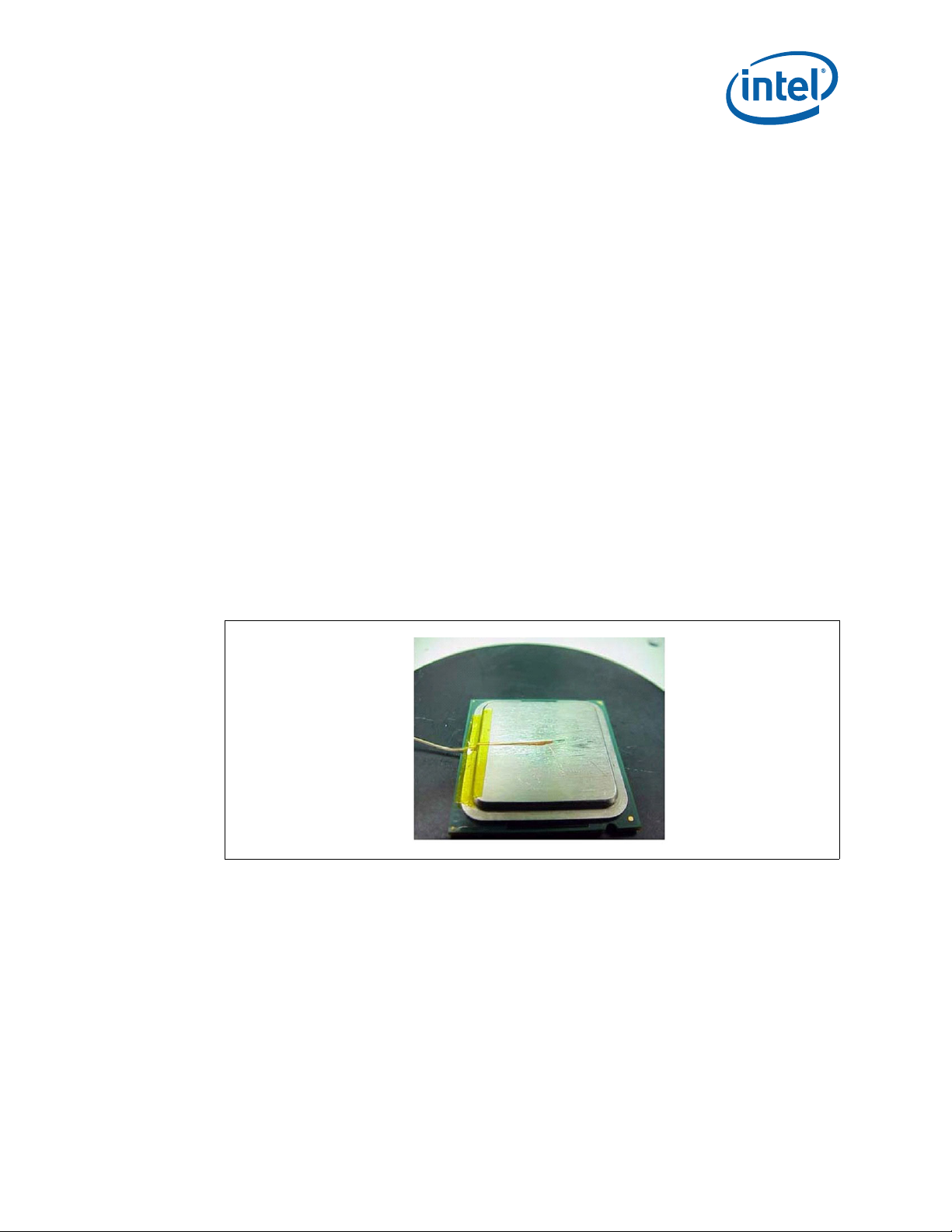
5.1 MCH Case Measurement
The Intel® 5100 MCH Chipset cooling performance is determined by measuring the
case temperature using a thermocouple. For case temperature measurements, the
attached method outlined in this section is recommended for mounti ng a
thermocouple.
Special care is required when measuring the case temperature (T
accurate temper ature measurement. Thermocouples are often used to measure T
) to ensure an
C
When measuring the temperature of a surface that is at a different temperature from
the surrounding local ambient air, errors may be introduced in the measure m en ts . The
measurement errors can be caused b y poor thermal cont act between the th ermocouple
junction and the surface of the integrated heat spreader, heat loss by radiation,
convection, by conduction through thermocouple leads, or by contact between the
thermocouple cement and the heatsink base. To minimize these measurement errors,
the approach outlined in the next section is recommended.
Note: The thermocouple attach example shown below is on a different package, but the
method and groove dimensions are the same. The the rmoco up le bead needs to be
centered on the IHS.
5.1.1 Supporting Test Equipment
T o a pply the refer ence the rmocoup le attach pr ocedure , it is recom mended th at you use
the equipment (or equivalent) given in Table 5.
.
C
July 2008 TDG
Order Number: 318676-003US 15
Intel® 5100 Memory Controller Hub Chipset for Communications, Embedded, and Storage Applications
Page 16

Intel® 5100 MCH Chipset
Table 5. Thermocouple Attach Support Equipment
Item Description Part Number
Measurement and Output
Microscope Olympus* light microscope or equivalent SZ-40
Digital multi-meter Digital multi-meter for resistance measurement Not Available
Test Fixture(s)
Micromanipulator set from YOU Ltd. or equivalent mechanical 3D arm with needle
Micromanipulator
Locite* 498* Super
Bonder* Instant
Adhesive Thermal
Cycling Resistant
Adhesive accelerator Locite 7452 Tak Pak* accelerator for fast glue curing 18490
Kapton tape For holding thermocouple in place or equivalent Not Available
Thermocouple OMEGA*, 36 gauge, “T” type 5SRTC-TT-36-72
ice point* Cell OMEGA, stable 0 °C temperature source for ca li brat ion a n d off set TRCIII
hot point* Cell OMEGA, temperature source to control and understand meter slope gain CL950-A-110
Notes:
1. Three axes set consists of (1 ea. U-31CF), (1 ea. UX-6-6), (1 ea. USM6) and (1 ea. UPN -1). Mor e info rmation is
available at http://www.narishige.co.jp/you/english/products/set/index.htm.
1
(not included) to maintain T
Super glue with thermal characteristics 49850
bead location during the attach process
C
Miscellaneous Hardware
Calibration and Control
YOU-3
5.1.2 Thermal Calibration and Controls
It is recommended that full and routine calibration of temperature measurement
equipment be perf or m ed before attempting to perform a temperature case
measurement of the Intel
®
5100 MCH Chipset. Intel recommends checking the meter
probe set against known standards. This should be done at 0 °C (using an ice bath or
other stable temperature source) and at an elev ated temper ature, around 80 °C (using
an appropriate temperature source).
Wire gauge and length also should be considered because some less expensive
measurement systems are heavily impacted by impedance. There are numerous
resources available throughout the industry to assist with implementation of proper
controls for thermal measurements.
Note: It is recommended to follow company standard procedures and wear safety items like
glasses for cutting the IHS and gloves for chemical handling.
Note: Ask your Intel field sales representative if you need assistance to groove and/or install
a thermocouple according to the reference process.
5.1.3 IHS Groove
Cut a groove in the package IH S according to the drawing given in Figure 6.
Note: The center of the round at the end of the IH S groove should be at the center of the
package.
®
5100 Memory Controller Hub Chipset for Communications, Embedded, and Storage Applications
Intel
TDG July 2008
16 Order Number: 318676-003US
Page 17

®
5100 MCH Chipset
Intel
Figure 6. IHS Groove Dimensions
July 2008 TDG
Order Number: 318676-003US 17
Intel® 5100 Memory Controller Hub Chipset for Communications, Embedded, and Storage Applications
Page 18

Intel® 5100 MCH Chipset
Figure 7. Orientation of Th ermocouple Groove Relative to Pac k age Pin
5.1.4 Thermocouple Conditioning and Preparation
1. Use a calibrated thermo c ou ple as specified in Table 5.
2. Measure the thermocouple resistance by holding both wires on one probe and the
tip of the thermocouple to the other probe of the DMM (compare to thermocouple
resistance specifications).
3. Straighten the wire for about 38 mm (1½") from the bead to place it inside the
channel.
4. Bend the tip of the thermocouple to approximate ly a 45 degree angle by 0.8 mm
(0.030") from th e tip (Figure 8).
Figure 8. B ending Tip of Thermocouple
5.1.5 Thermocouple Attachment to IHS
Caution: To avoid impact on the thermocouple during the SMT process, reflow must be
performed before attaching the thermocouple to the grooved MCH IHS.
1. Clean the ther moc ouple wire groov e with isopropyl alcohol (IPA) and a lint-free
cloth removing all residue prior to thermocouple attachment.
®
5100 Memory Controller Hub Chipset for Communications, Embedded, and Storage Applications
Intel
TDG July 2008
18 Order Number: 318676-003US
Page 19
®
5100 MCH Chipset
Intel
2. Place the thermocouple wire inside the groove letting the exposed wire and bead
extend about 3.2 mm (0.125") past the end of the groov e. Secure it with Kapt on
tape (Figure 9).
3. Lift the wire at th e middle of gro ove with t weezers and ben d the front of th e wire to
place the thermocoupl e in the channel ensuring that the tip is in contact with the
end of the channel grooved in the IHS (Figure 10 A and B).
4. Place the MCH under the microscope unit (similar to the one used in Figure 13) to
continue with the process. It is also recommended to use a fixture to help hold the
unit in place for the rest of the attach process.
5. Press the wire down about 6 mm (0.125") from the thermocouple bead using the
tweezers. Look in the micros cope to perform this task . Place a piece of Kap ton tape
to hold the wire inside the groove (Figure 12). Refer to Figure 11 for detailed bead
placement.
6. Using the micromanipulator, place the needle near th e end of groove on top of the
thermocouple. Usin g the X , Y, and Z ax es on the arm, place the tip of th e ne edle on
top of the thermocouple bead. Press down until the bead is seated at the en d of the
groove on top of the step (see Figure 11 and Figure 12).
7. Measure resistance from thermocouple end wires (hold both wires to a DMM probe)
to the IHS surface. This should be the same value as measured during the
thermocouple conditioning. See Section 5.1.4, step 2., and Figure 13.
8. Place a small amount of Locite * 498* Supe r Bonder* adh esive i n the groo ve where
the bead is installed. Using a fine point device, spread the adhesive in the groove
around the needle, the th ermocouple bead, and the thermocoupl e wires already
installed in the g r oove during step 5. Be c a r e ful not to move th e thermocouple
bead during this step (Figure 14).
Figure 9. Securing Thermocouple Wires with Kapton Tape Prior to Attach
July 2008 TDG
Order Number: 318676-003US 19
Intel® 5100 Memory Controller Hub Chipset for Communications, Embedded, and Storage Applications
Page 20

Figure 10. Thermocouple Bead Placement
Intel® 5100 MCH Chipset
Figure 11. Positioning Bead on Gr oo ve
®
5100 Memory Controller Hub Chipset for Communications, Embedded, and Storage Applications
Intel
TDG July 2008
20 Order Number: 318676-003US
Page 21

®
5100 MCH Chipset
Intel
Figure 12. Using 3D Micromanipulator to Secure Bead Location
Figure 13. Measuring Resistance between Thermocouple and IHS
July 2008 TDG
Order Number: 318676-003US 21
Intel® 5100 Memory Controller Hub Chipset for Communications, Embedded, and Storage Applications
Page 22

Figure 14. Applying Adhesiv e on Thermocouple Bead
5.1.6 Curing Process
1. Let the thermocouple attach sit in the open air for at least half an hour. Using any
curing accelerator like the Locite* 7452 Tak Pak* accelerator for this step is not
recommended. Rapid contraction of the adhesive during curing may weaken bead
attach on the IHS .
2. Reconfirm electrical connectivity with the DMM before removing the
micromanipulator. See Section 5.1.4, step 2., and Figure 13.
3. Remove the 3D arm needle by holding down the MCH un it an d lifting the arm.
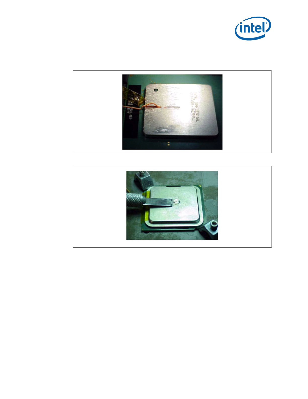
4. Remove the Kapton tape, and straighten the wire in the groove so that it is flat all
the way to the en d of the groove (Figure 15).
5. Using a blade, shave excess adhesive above the IHS surface (Figure 16).
Intel® 5100 MCH Chipset
Note: Take usual prec autions when using ope n blades.
6. Install new K apto n tape t o hold the thermo couple wire dow n, an d fill th e rest of the
groove with adhesive (Figure 17). Make sure the wire an d insulation is entir ely
within the groove and below the IHS su r fa c e.
7. Curing time for the rest of the adhesive in the groove can be reduced using the
Locite* 7452 Tak Pak* acceler a tor.
8. Repeat step 5. to remove any access adhesive to ensure a flat IHS for proper
mechanical contact to the heatsink surface.
®
5100 Memory Controller Hub Chipset for Communications, Embedded, and Storage Applications
Intel
TDG July 2008
22 Order Number: 318676-003US
Page 23
®
5100 MCH Chipset
Intel
5.1.7 Ther mocouple Wire Management
Figure 15. Thermocouple Wire Management in Groove
Figure 16. Removing Excess Adhe sive from IHS
July 2008 TDG
Order Number: 318676-003US 23
Intel® 5100 Memory Controller Hub Chipset for Communications, Embedded, and Storage Applications
Page 24

Figure 17. Filling Groove with Adhesive
Intel® 5100 MCH Chipset
Note: Prior to installing the heatsink, be sure that the thermocouple wires remain below the
IHS top surface by running a flat blade on top of the IHS, for example.
5.2 Power Simulation Software
Power simulation software now exists for the Intel® 5100 MCH Chipse t. The power
simulation software is a utility designed to dissipate the thermal design power on a
®
5100 MCH Chipset when used in conjunction with the Dual-Core Intel® Xeon®
Intel
processor 5X00 series. The combination of the above mentioned processor(s) and the
higher bandwidth capabil ity of the Intel
®
5100 MCH Chipset enables higher levels of
system performance. To assess the thermal performance of the MCH chipset thermal
solution under “worst-case realistic application” conditions, Intel developed a software
utility that operates the chipset at near worst-case thermal power dissipation.
The power simulation software developed should only be used to test thermal solutions
at or near the thermal design power. Real world applications may exceed the thermal
design power limit for transient time periods. For power supply current requirements
under these transient conditions, please refer to each component’s datasheet for the
ICC (Max Power Supply Current) specification. Contact your Intel field sales
representative to order the power simulation software: Intel
®
5100 Memory Controller
Hub Chipset (embedded) – Maximum Pow er Application.
6.0 Reference Thermal Solution
Intel has developed two referen ce therm al solut ions t hat meet the cooli ng needs of the
®
5100 MCH Chipset under the embedded operating en vironments and
Intel
specifications defined in this document. This chapter describes the overall requirements
for the torsional clip heatsink reference thermal solution including critical-to-function
dimensions, op erating environment, and valid ation criteria. Other c hipset components
may or may not need attached thermal solutions depending on your specific system
local-ambient operating conditions. For information on the ICH9R, refer to the thermal
specificat ion in the Intel
Design Guidelin es.
®
I/O Controller Hub 9 (ICH9) Family Thermal and Mechanical
®
5100 Memory Controller Hub Chipset for Communications, Embedded, and Storage Applications
Intel
TDG July 2008
24 Order Number: 318676-003US
Page 25

®
0.000
0.500
1.000
1.500
2.000
2.500
3.000
3.500
4.000
4.500
0 100 200 300 400 500 600 700 800 900 1000 1100 1200 1300
Airf low Approach Velocity (LFM)
Case-to-Ambient Thermal Characterization Parameter,
Ψ
CA
(°C/W)
ATCA Heatsink
AdvancedTCA* Heatsink
5100 MCH Chipset
Intel
The Intel® 5100 MCH Chipset has a lower TDP than the Intel® 5000 Series Chipset and
a similar package size. Due to this, any thermal solutions for the Intel
Chipset should be reusable for the Intel
®
5100 MCH Chipset inc luding the Intel
®
5000 Series
reference solutions. The system designer still needs to verify that the entire thermal
solution will me et the component temperatur e s pe cifications and TDP in the intended
system.
6.1 AdvancedTCA* Reference Heatsink
6.1.1 Thermal Performance
The AdvancedTCA* reference heatsink should be made from aluminum to achieve the
necessary thermal performance. Depending on the boundary conditions, the referenc e
heatsink can meet the thermal performance needed t o c ool the Intel
Chipset in the AdvancedTCA* form factor. The heatsink performance versus airflow
velocity is show n in Figure 18. The heatsink may be used in other form factors that can
provide the required amount of airflow to meet the compon ents thermal specifications .
Figure 18. Torsional Clip Heatsink Measured Thermal Performance versus Approach
Velocity
®
5100 MCH
6.1.2 Mechanical Design Envelope
While each design may have unique mechanical volume and height restrictions or
implementation requirements, the height, width, and depth constraints typically placed
on the Intel
July 2008 TDG
Order Number: 318676-003US 25
®
5100 MCH Chipset thermal solution are shown in Figure 19.
Intel® 5100 Memory Controller Hub Chipset for Communications, Embedded, and Storage Applications
Page 26

Intel® 5100 MCH Chipset
When using heatsinks that extend beyond the MCH chipset reference heatsink envelope
shown in Figure 19, any motherboard components placed between the heatsink and
motherboard cannot exceed 2 mm (0.07") in height.
Figure 19. AdvancedTCA* Torsional Clip Heatsink Volumetric Envelope fo r M CH Heatsink
6.1.3 Board-level Components Keepout Dimensions
The location of hole patterns and keepout zones for the AdvancedTCA* reference
thermal soluti on are shown in Figure 25. This reference thermal solution has the same
hole patterns as that of the Intel
®
E7500 Series Chipset and Intel® 5000 Series
Chipset.
6.1.4 Torsional Clip Heatsink Thermal Solution Assembly
The reference thermal solution for the MCH is a passive extruded heatsink with a
thermal interface. It is attached using a clip with each end hook ed through an anchor
soldered to the board. Figure 20 shows the reference thermal solution assembly and
associated components. The torsional clip and the clip retention anchor are the same as
the ones used on the Intel
®
5100 Memory Controller Hub Chipset for Communications, Embedded, and Storage Applications
Intel
TDG July 2008
26 Order Number: 318676-003US
®
E7500 Series Chipset ref eren c e thermal solution.
Page 27

®
5100 MCH Chipset
Intel
Full mechanical drawings of the thermal solution assembly and the heatsink clip are
provided in Appendix A. Appendix B contains vendor information for each therma l
solution component.
6.1.5 Heatsink Orientation
Because this solution is based on a unidirectional heatsink, the mean airflow direction
must be aligned with the direction of the heatsink fins.
Figure 20. Torsional Clip He a t sink Assembly
6.1.6 Extruded Heatsink Profiles
The reference the r m al s ol u t ion uses an extruded heats ink for cooling the MCH.
Appendix B lists a supplier for this extruded heatsink. Other heatsinks with similar
dimensions and incr ea s ed thermal performance may be a vailable. A full mechanical
drawing of this heatsink is provided in Appendix A.
6.1.7 Mechanical Interface Material
There is no mechanical interface material associated with this reference solution.
6.1.8 Thermal Interface Mater ial
A thermal interface materi al (TIM) provides improv ed conductivity between the IHS
and heatsink. The reference thermal solution uses Honeywell* PCM45F, 0.25 mm
(0.010") thick, 25 mm x 25 mm (0.984" x 0.984") squared.
Note: Unflowed or “dry” Honeywell* PCM45F has a material thickness of 0.010". The flowed
or “wet” Honeywell* PCM45F has a material thickness of ~0.003" after it reaches its
phase change temperature.
July 2008 TDG
Order Number: 318676-003US 27
Intel® 5100 Memory Controller Hub Chipset for Communications, Embedded, and Storage Applications
Page 28

Intel® 5100 MCH Chipset
6.1.8.1 Effect of Pressure on TIM Performance
As mechanical pressure increases on the TIM, the thermal resistance of the TIM
decreases. This phenomenon is due to the decrease of the bond line thickness (BLT).
BLT is the final settled thickness of the thermal interface material after installation of
heatsink. The effect of pressure on the thermal resistance of the Honeywell* PCM45F
TIM is shown in Table 6.
Intel provides both End of Line and End of Life TIM thermal resistance values of
Honeywell* PC M45F. End of Line and End of Li fe TIM thermal resistance values ar e
obtained through meas urement on a Test Vehicle similar to the In tel
Chipset’s physical attributes using an extruded aluminum heatsink. The End of Line
value represents the TIM performance post heats in k as s embly, while the End of Life
value is the predicted TIM performance when the product and TIM reaches the end of
its life. The heatsink clip provides enough pressure for the TIM to achieve an End of
Line thermal resistance of 0.345 (°C × inches
2
)/W and End of Life thermal resistance of
0.459 (°C × inches2)/W.
Table 6. Honeywell* PCM45F TIM Performance as Function of Attach Pressure
Pressure (psi)
2.18 0.319 0.551
4.35 0.345 0.459
Thermal Resistance (°C × inches
End of Line End of Life
®
5000 Series
2
)/W
6.1.9 Heatsink Clip
The reference solution uses a wire clip with hooked ends. The hooks attach to wire
anchors to fasten the clip to the board. See Appendix A for a mechanical drawing of the
clip.
6.1.10 Clip Retention Anchors
For Intel® 5100 MCH Chipset-based platforms that have very limited board space, a
clip retention anchor has been developed to minimize the impact of clip retention on
the board. It is based on a standard t hre e-pin jumper and is sold ered to the board like
any common through- hole header. A new an ch o r d esi gn is available with 45 degree
angle bent leads to increase the anchor attach reliability ov er time. See Appendix B for
the part number and supplier information.
6.1.11 Reliability Guidelines
Each motherboard, heatsink, and attach combination may vary the mechanical loading
of the component. Bas e d on the end user environm ent, the user should def ine the
appropriate reliability test criteria a nd carefully eval ua te the completed assemb ly prior
to use in high volume. Some general recommendations are shown in Table 7.
®
5100 Memory Controller Hub Chipset for Communications, Embedded, and Storage Applications
Intel
TDG July 2008
28 Order Number: 318676-003US
Page 29

®
5100 MCH Chipset
Intel
Table 7. Reliability Guidelines
1
Test
Mechanical Shock 50 g, board level, 11 ms, three shocks/axis Visual Check and Electrical Functional Test
Random Vibration 7.3 g, board level, 45 minutes/axis, 50 Hz to 2000 Hz Visual Check and Electrical Functional Test
Temperature Life
Thermal Cycling -5 °C to +70 °C, 500 cycles Visual Check
Humidity 85% relative humidity, 55 °C, 1000 hours Visual Check
Notes:
1. It is recommende d that t h e above tests be performed on a sample size of at least 12 assembl i e s fr om thr e e lots of
2. Additional pass/fail criteria may be added at the discretion of the user.
material.
85 °C, 2000 hours total, checkpoints at 168, 500, 1000,
and 2000 hours
Requirement Pass/Fail Criteria
Visual Check
2
6.2 CompactPCI* Reference Heatsink
Intel has also developed a reference thermal solution compatible with the CompactPCI*
form factor. The reference solution was developed assuming a maximum ambient
temperature of 67 °C with a minimum volumetric airflow rate of 10 CFM through each
slot. Assuming these boundary conditions are met, the reference thermal solution
meets the thermal specifications for Intel
®
5100 Memory Controller Hub Chipset.
6.2.1 Component Overview
The CompactPCI* reference heatsink is an extruded aluminum heatsink and does not
share the same volumetric footprint as the Adv a ncedTCA* referenc e heatsink. Full
mechanical drawings of the thermal solution assembly, full mechanical drawings,
volumetric foot print, and the he atsink clip ar e provided in Appendix A. It uses the same
spring clip retention and Honeywell* PCM45F Thermal Interface Material (TIM) as the
AdvancedTCA* reference solution.
Figure 21 shows the isometric view of the CompactPCI* reference heatsink.
Figure 21. Isometric View of the CompactPCI* Reference Heatsink
Note: Refer to Appendix A for more detailed mechanical drawings of the heatsink.
July 2008 TDG
Order Number: 318676-003US 29
Intel® 5100 Memory Controller Hub Chipset for Communications, Embedded, and Storage Applications
Page 30

6.2.2 Thermal Solution Performance Characteristics
0
0.5
1
1.5
2
2.5
3
3.5
4
0 100 200 300 400 500 600 700 800 900 1000 1100 1200
Airfl o w App r oach V el o ci ty (L F M )
Case-To-Amb ient Th erm al Characteriz ation P aram eter
Ψ
ca
(
o
C/W)
CompactPCI* Heatsink
Figure 22 shows the performance of the CompactPCI* reference heatsink. This figure
shows the thermal performance of the heatsink versus the airflow approach velocity
provided.
Figure 22. CompactPCI* Reference Heatsin k Thermal Perfor m ance
Intel® 5100 MCH Chipset
7.0 Reliability Guidelines
Table 8. Reliability Requirements
Test
Mechanical Shock 50 g, board level, 11 ms, three shocks/axis Visual Check and Electrical Functional Test
Random Vibration 7.3 g, board level, 45 minutes/axis, 50 Hz to 2000 Hz Visual Check and Electrical Functional Test
Temperature Life
Thermal Cycling -5 °C to +70 °C, 500 cycles Visual Check
Humidity 85% relative humidity, 55 °C, 1000 hours Visual Check
Notes:
1. The above tests should be performed on a sa mple size of at least 12 assemblies from three lots of material.
2. Additional pass/fail criteria may be added at the discretion of the user.
®
5100 Memory Controller Hub Chipset for Communications, Embedded, and Storage Applications
Intel
TDG July 2008
30 Order Number: 318676-003US
Each motherboard, heatsink, and attach combination may vary the mechanical loading
of the component. The user should ca r efully evaluate the relia b ility of the complete d
assembly prior to use in high volume. Some general reco mmendations are shown in
Table 8.
1
85 °C, 2000 hours total, checkpoints at 168, 500, 1000,
and 2000 hours
Requirement Pass/Fail Criteria
Visual Check
2
Page 31

®
5100 MCH Chipset
Intel
Appendix A Mechanical Drawings
Table 9 lists the me c hanical drawings inc luded in this appendix.
Table 9. Mechanical Drawing List
Drawing Description Figure Number
AdvancedTCA* Heatsink Assemb ly Figure 23
AdvancedTCA* Heatsink Figure 24
AdvancedTCA* Compon ent Keepout Zone Figure 25
CompactPCI* Heatsi nk Assembly Figure 26
CompactPCI* Heatsink Figure 27
CompactPCI* Compo nent Keepout Zone Figure 28
Reference Heatsink Torsional Clip Figure 29
TIM2 Figure 30
July 2008 TDG
Order Number: 318676-003US 31
Intel® 5100 Memory Controller Hub Chipset for Communications, Embedded, and Storage Applications
Page 32

Figure 23. AdvancedTCA* Heatsink Assembly Drawing
Intel® 5100 MCH Chipset
®
5100 Memory Controller Hub Chipset for Communications, Embedded, and Storage Applications
Intel
TDG July 2008
32 Order Number: 318676-003US
Page 33

®
5100 MCH Chipset
Intel
Figure 24. AdvancedTCA* Heatsink Drawing
July 2008 TDG
Order Number: 318676-003US 33
Intel® 5100 Memory Controller Hub Chipset for Communications, Embedded, and Storage Applications
Page 34

Figure 25. AdvancedTCA* Component Keepout Zone
Intel® 5100 MCH Chipset
®
5100 Memory Controller Hub Chipset for Communications, Embedded, and Storage Applications
Intel
TDG July 2008
34 Order Number: 318676-003US
Page 35

®
5100 MCH Chipset
Intel
Figure 26. CompactPCI* Heatsink Assembly Drawing
July 2008 TDG
Order Number: 318676-003US 35
Intel® 5100 Memory Controller Hub Chipset for Communications, Embedded, and Storage Applications
Page 36

Figure 27. CompactPCI* Heatsink Drawing
Intel® 5100 MCH Chipset
®
5100 Memory Controller Hub Chipset for Communications, Embedded, and Storage Applications
Intel
TDG July 2008
36 Order Number: 318676-003US
Page 37

®
5100 MCH Chipset
Intel
Figure 28. CompactPCI* Component Kee pout Zone
July 2008 TDG
Order Number: 318676-003US 37
Intel® 5100 Memory Controller Hub Chipset for Communications, Embedded, and Storage Applications
Page 38
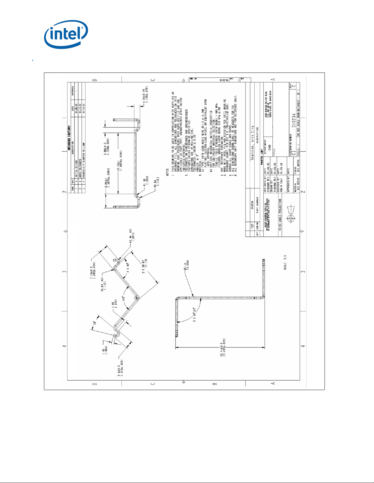
Figure 29. Torsional Clip Heatsink Clip Drawing
Intel® 5100 MCH Chipset
®
5100 Memory Controller Hub Chipset for Communications, Embedded, and Storage Applications
Intel
TDG July 2008
38 Order Number: 318676-003US
Page 39

®
5100 MCH Chipset
Intel
Figure 30. TIM2 Drawing
July 2008 TDG
Order Number: 318676-003US 39
Intel® 5100 Memory Controller Hub Chipset for Communications, Embedded, and Storage Applications
Page 40

Intel® 5100 MCH Chipset
Appendix B Thermal Solution Component Suppliers
Table 10. MCH Torsion a l Clip Heatsink Therma l Solution
Part Intel Part Number Supplier (Part Number) Contact Information
AdvancedTCA*
reference heatsink
heatsink
Thermal interface C34795-001 Honeywell* (PCM45F)
Heatsink attach clip D10234-001
Solder-down anchor A13494-005 Foxconn (HB96030-DW)
Note: The enabled components may not be currently available from all suppliers. Contact the supplier
directly to verify the time of component availability.
D96852-001
E45550-001
Cooler Master*
(ECC-00527-01-GP)
Cooler Master*
(ECB-00590-01-GP)
CCI*/ACK
Foxconn*
Wendy Lin (USA)
510-770-8566 x211
wendy@coolermaster.comCompactPCI* reference
Scott Miller
509-252-2206
scott.miller4@honeywell.com
Paula Knoll
858-279-2956
paula_knoll@honeywell.com
Harry Lin (USA)
714-739-5797
hlinack@aol.com
Monica Chih (Taiwan)
866-2-29952666, x1131
monica_chih@ccic.com.tw
Bob Hall (USA)
503-693-3509, x235
bhall@foxconn.com
Julia Jiang (U SA)
408-919-6178
juliaj@foxconn.com
®
5100 Memory Controller Hub Chipset for Communications, Embedded, and Storage Applications
Intel
TDG July 2008
40 Order Number: 318676-003US
 Loading...