

Intel WEAP2011AR, WEAP2011NA,WEAP2011EU,WEAP2011JP,WEAP2011AR,WEAP2011SG,WEAP2011KR,WEAP2011EO,WEAP2011BAK,WEAP2011BRW,WEAP2011BJP, WEAP2011NA, WEAP2011SG, WEAP2011KR Configuration Manual
...Page 1

Intel® PRO/Wireless 2011/2011B LAN
Configuring Access Point Bridging and Re peating (WLAP
Mode)
Page 2

Product Model
Intel® PRO/Wireless 2011/2011B LAN Adapter product models:
WEAP2011NA
WEAP2011EU
WEAP2011JP
WEAP2011AR
WEAP2011SG
WEAP2011KR
WEAP2011EO
WEAP2011BAK
WEAP2011BRW
WEAP2011BJP
Copyright
Copyright © 2001, 2002 Intel Corpora t ion . Al l right s rese rved.
Intel Corporation, 5200 N. E. Elam Young Parkway, Hillsboro, OR 97124-6497
Intel Corporation assumes no responsibility for errors or omissions in this document. Nor does Intel make any commitment to update the
information contained herein.
Intel® PRO/Wireless 2011/2011B LAN is a registered tra dem ark of Intel Corporation.
†Other product and corporate names mentioned herein may be trademarks of other companies and are used only for explanation and to the owners’
benefit, without intent to infringe.
ii Configuring Access Point Bridging and Repeating (WLAP Mode)
A79771-001
Page 3

About This Docum ent
Conventions
Keystrokes are indicated as follows:
ENTER identifies a key.
FUNC, CTRL, C identifies a key sequence. Press and release each key in turn.
Press A+B press the indicated keys simultaneously.
Hold A+B press and hold the indicated keys while performing or waiting for another
function. Used in combination with another keystroke.
Typeface conventions used include.
<angles> indicates mandatory parameters in sy ntax.
[brackets] for command line, indicates available parameters; in configuration files,
brackets act as separators for options.
GUI Screen text
Italics indicates the first use of a term, book title, variable or menu title.
Bold indicates important user information, license provisions or warranty
Screen dialog
Screen text
Terminal text
Terminal text
Terminal textTerminal text
URL
indicates the name of a control in a GUI-based application.
conditions.
indicates screen dialog and user input options, and the exact syntax of items.
indicates text and data displayed in an application screen on a computer
monitor.
indicates text shown in a radio terminal LCD screen.
indicates a Uniform Resource Locator, such as a Web page address.
About This Document
Configuring Access Point Bridging and Repeating (WLAP Mode) iii
Page 4

About This Document
This document uses the following for certain conditions or information:
indicates tips or special requirements.
indicates conditions that can cause equipment damage or data loss.
indicates a potentially dangerous condition or procedure that only Intel® PRO/Wireless 2011/
2011B LAN-trained personnel should attempt to correct or perform.
iv Configuring Access Point Bridging and Repeating (WLAP Mode)
Page 5

Contents
Contents
Product Model.............................................................................................................. ii
Copyright...................................................................................................................... ii
About This Document.................................................................................iii
Conventions ................................................................................................................ iii
Contents......................................................................................................v
Chapter 1. Introduction.....................................................................................................................1
1.1 Basic Settings for Access Points............................... ....... ...... ....... ...... ...................1
1.2 Recommended Settings for Root Access Point .....................................................2
Chapter 2. Extending a Net work’s Radio Coverage ................................................................4
2.1 One-Hop Wireless Network Example.....................................................................4
2.2 Two-Hop Wireless Network Example.....................................................................4
Chapter 3. Verifying Wireless AP Operations............................................................................6
3.1 Viewing the WLAP RF Statistics Screen................................................................6
3.2 Viewing the Known Access Points Screen.............................................................7
3.3 Observing the Access Point’s LED Indicators........................................................8
3.3.1 Functional State............................................................................................9
3.3.2 Send Probe State .........................................................................................9
Chapter 4. Using the Link Required Option..............................................................................11
4.1 Link Required for Maintaining Ethernet Link ........................................................11
4.2 Link Required for Backing Up Root Access Point................................................13
Chapter 5. Bridging Two Ethernet Networks............................................................................16
5.1 Verifying the Bridging Operation ..........................................................................16
5.2 Using the Ethernet Timeout Settings 2 & 3..........................................................17
5.2.1 Ethernet Timeouts and Access Point Settings............................................18
5.2.2 Sequence of Events in Special Network.....................................................20
5.3 Using the Ethernet Timeout Setting 4 ..................................................................21
Chapter 6. RF Link Test.................................................................................................................22
6.1 Basic Setup for the RF Link Test .........................................................................22
6.2 The Connection Quality Test Screen ...................................................................23
6.2.1 Low and Zero RSSI Readings....................................................................24
6.3 Preparing for the RF Link Test.............................................................................25
6.4 Running the RF Link Test ....................................................................................25
6.4.1 Running the RF Link Test with Telnet.........................................................27
6.5 Using RF Link Test with Mobile Units ..................................................................29
6.6 Using RF Link Test to Align Directional Antennas ...............................................30
6.6.1 Setting Up for the Antenna Alignment Procedure.......................................31
6.6.2 Procedure for Aligning Directional Antennas..............................................32
6.6.3 Additional Suggestions on Antenna Alignment...........................................34
Omni-Directional Antenna...........................................................................................34
Configuring Access Point Bridging and Repeating (WLAP Mode) v
Page 6

Contents
Other Equipment.........................................................................................................35
Chapter 7. Re gulatory Compliance Information......................................................................36
Index.........................................................................................................................................................37
vi Configuring Access Point Bridging and Repeating (WLAP Mode)
Page 7
Chapter 1. Introduction
This document describes how to set up an Intel® PRO/Wireless 2011/2011B LAN Access Point.
For the Intel® PRO/Wireless 2011B LAN Access Point, the firmware is version 3.x. For the Intel®
PRO/Wireless 2011 LAN Access Point, the firmware is version 2.5x.
The features in the access point firmware allow network communication between access points.
You can use access points to extend radio coverage of a single Ethernet network or to bridge two
Ethernet networks.
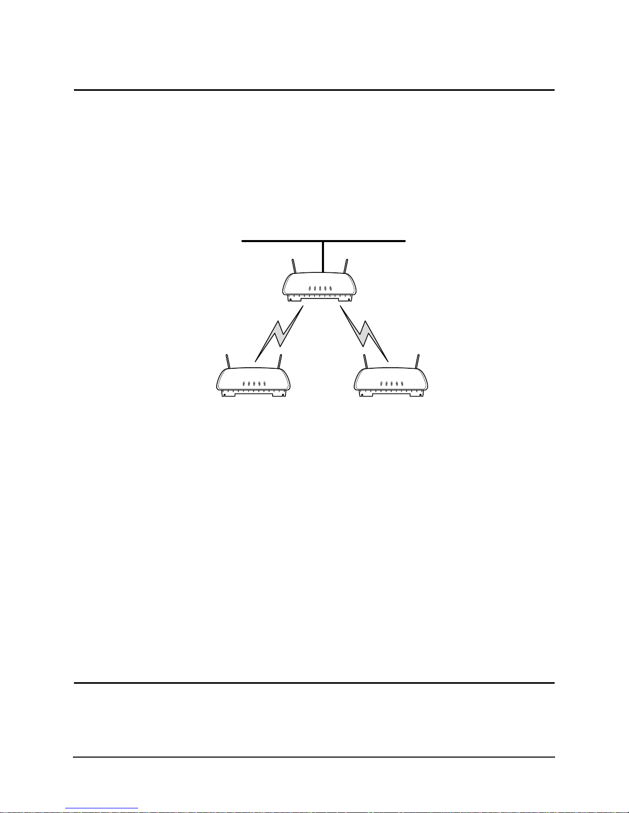
A wireless network consists of a root Wireless Access Point (WLAP) and one or more designated
WLAPs. The root access point is typically connected to the Ethernet network; although, this is not
a requirement. The network in Figure 1-1 uses two access points operating in the wireless mode to
extend radio coverage. The solid line in the figure represents an Ethernet network.
A
BC
Figure 1-1: Extending Network Radio Coverage Using Wireless Access Points
Access points maintain their wireless connections through the radio broadcasting of probe, bea con,
and Bridge Protocol Data Unit (BPDU) messages. Probe and beacon messages are part of the
802.11 protocol. BPDU messages are part of the Spanning Tree Pro tocol.
At the start of a wireless connection, access points send out probe requests and probe responses to
gather operating status of other access points. Designated WLAPs also send out probes if they lose
the beacon message from the root access point. The beacon messages are broadcast by the access
points to keep the network synchronized. It contains information such as the access point’s
Extended Service Set Identifier (ESS ID) and MAC address. The ESS ID is also called the Network
Name or SSID.
There are two types of BPDU messages. One type is a configuration BPDU. At the start of the
wireless connection, the configuration BPDU messages determine the network configuration for
the root access point and designated WLAPs. The other type of BPDU is the WLAP-Alive. These
messages keep track of access points operating in the wireless network.
The procedures and e xamples in this d ocum ent ar e fo r I ntel® PRO/Wireless 2011 and 2011B LAN
Access Points with firmware version 2.5x or higher. Additional information on access points is
available in the Intel® PRO/Wireless 2011/2011B LAN Point Product Reference Guides available
on the Intel support web site at www.support.Intel.com.
1.1 Basic Settings for Access Points
For a wi reless Access Point (AP) operation, make sure that all access points have:
• The same ESS ID (Net ID) on the Access Point Installation screen. An example screen is
Configuring Access Point Bridging and Repeating (WLAP Mode) 1
Page 8

Chapter 1. Introduction
shown in Figure 1-2. The ESS ID is sometimes referred to as a SSID or Network Name.
• The WLAP Mode set to
screen is shown in Figure 1-3.
• The same settings for the Rate Control and Short RF Preamble. These settings are on the RF
Configuration screen. An example is shown in Figure 1-3. Rates set to
which all access points in the network must be capable of operating.
which access points may operate if they are capable. This is to accommodate other
manufacturers’ access points that operate only at the 1- and 2-Mbps rates. For example, if all
rates are set to
associate. If only the 1- and 2-Mbps rates (or only the 1-Mbps rate) are set to
older access points would associate. Intel recommends setting rates 1 and 2 Mbps to
and 5.5 and 11 Mbps to
• The same setting for the Wir ed Eq uivalent Privacy (WEP) an d WEP Algorithm. Thes e settings
are on the RF Configuration screen. An example is shown in Figure 1-3.
After making these settings, save them by pressing the
Enabled. This setting is on the RF Configuration screen. An example
Required are those at
Optional rates are those at
Required, older access points that operate at only 1 and 2 Mbps would not
Required, the
Required
Optional as shown in the example screen of Figure 1-3.
F1 key. Reset the access point.
Access Point A
.Country Config-[CR] United States
Unit Name Access Point A
IP Address 157.235.55.199
.Gateway IP Address 0.0.0.0 0.0.0.0
.Subnet Mask 255.255.255.0 0.0.0.0
.DNS IP Address 0.0.0.0 0.0.0.0
.Net_ID (ESS) Warehouse 1
.Antenna Selection Full Diversity
.DHCP/BOOTP Disabled 0.0.0.0
OK-[CR] Save-[F1] Save All APs-[F2] Cancel-[ESC]
(Most parameters take effect only after being saved and AP is reset)
Identifies this Wireless LAN (1-32 characters)
Access Point Installation
.Additional Gateways
0.0.0.0
0.0.0.0
0.0.0.0
0.0.0.0
.Additional DNS
0.0.0.0
Figure 1-2: Setting the ESS ID (Network Name/SSID)
1.2 Recommended Settings for Root Access Point
On the root access point, pay attention to the following settings on the RF Configuration screen, as
shown on Figure 1-3:
• WLAP Priority
• WLAP Manual BSS ID
WLAP Priority
Set the root access point’s WLAP Priority setting to a lower number such as 7000 hex. The default
value for the WLAP Priority setting is 8000 hex, and it has a range from 0000 through FFFF hex.
Changing the WLAP Priority to a lower number ensures that the access point is recognized as the
root access point. A WLAP ID is created for each access point from a concatenation of its WLAP
Priority number and its MAC address. The priority n umber becomes the mo st-signif ican t portion of
the WLAP ID. The access point with the lowest WLAP ID becomes the root access point.
2 Configuring Access Point Bridging and Repeating (WLAP Mode)
Page 9

After the wireless network is running, observe the WLAP ID from the WLAP RF Statistics screen.
Display this screen by pre ssing
WLAP Manual BSS ID
Intel recommends that you set the WLAP Manual BSS ID to its own MAC address. An example is
shown in Figure 1-3. This caus es the access point to go directly to the Functional state and therefo re
reduces the time required to begin the wireless connection. The Functional state is described in
section 3.3.1: Functional State.
F3 from the RF Statistics screen.
Access Point A
.DTIM Interval 10 WLAP Mode Enabled
.BC/MC Q Max 10
.Max Retries (d) 15 WLAP Priority 7000 hex
.Max Retries (v) 5 WLAP Manual BSS ID 00:A0:F8:93:C5:B5
.Multicast Mask (d) 09000E00 hex
.Multicast Mask (v) 01005E00 hex WLAP Hello Time 20
.Beacon Interval 100 K-us WLAP Max Age 100
.Accept Broadcast ESSID Disabled WLAP Forward Delay 5
.MU Inactivity Timeout 60 min. WLAP MU Table Aging Time 240 min.
.Rate Control
11 Mb/s Optional .WEP (Privacy) Disabled
5.5 Mb/s Optional .WEP Algorithm 40 bit shared key
2 Mb/s Required .Encryption Key ID 1
1 Mb/s Required Encryption Key Maintenance
.RTS Threshold 2347 bytes
Extended Range 0 mi. Tx Power Control Full
OK-[CR] Save-[F1] Save All APs-[F2] Cancel-[ESC]
Use the space bar to enable/disable/set link required WLAP operation.
RF Configuration
.Short RF Preamble Disabled
Figure 1-3: Example Settings for the Root Access Point
Configuring Access Point Bridging and Repeating (WLAP Mode) 3
Page 10
Chapter 2. Extending a Network’s Radio Coverage
Chapter 2. Extending a Network’s Radio Coverage
This section covers examples for extending the radio coverage of a single Ethernet network with
one-hop and two-hop wireless AP operations. The term “hop” refers to the direct communications
link between two nodes of a network. With regard to wireless AP operations, the number of hops
refers to the number of direct links through which a message passes between the root access point
and a particular designated WLAP. Examples of one-hop and two-hop operations are shown in
Figure 2-1 and Figure 2-2.
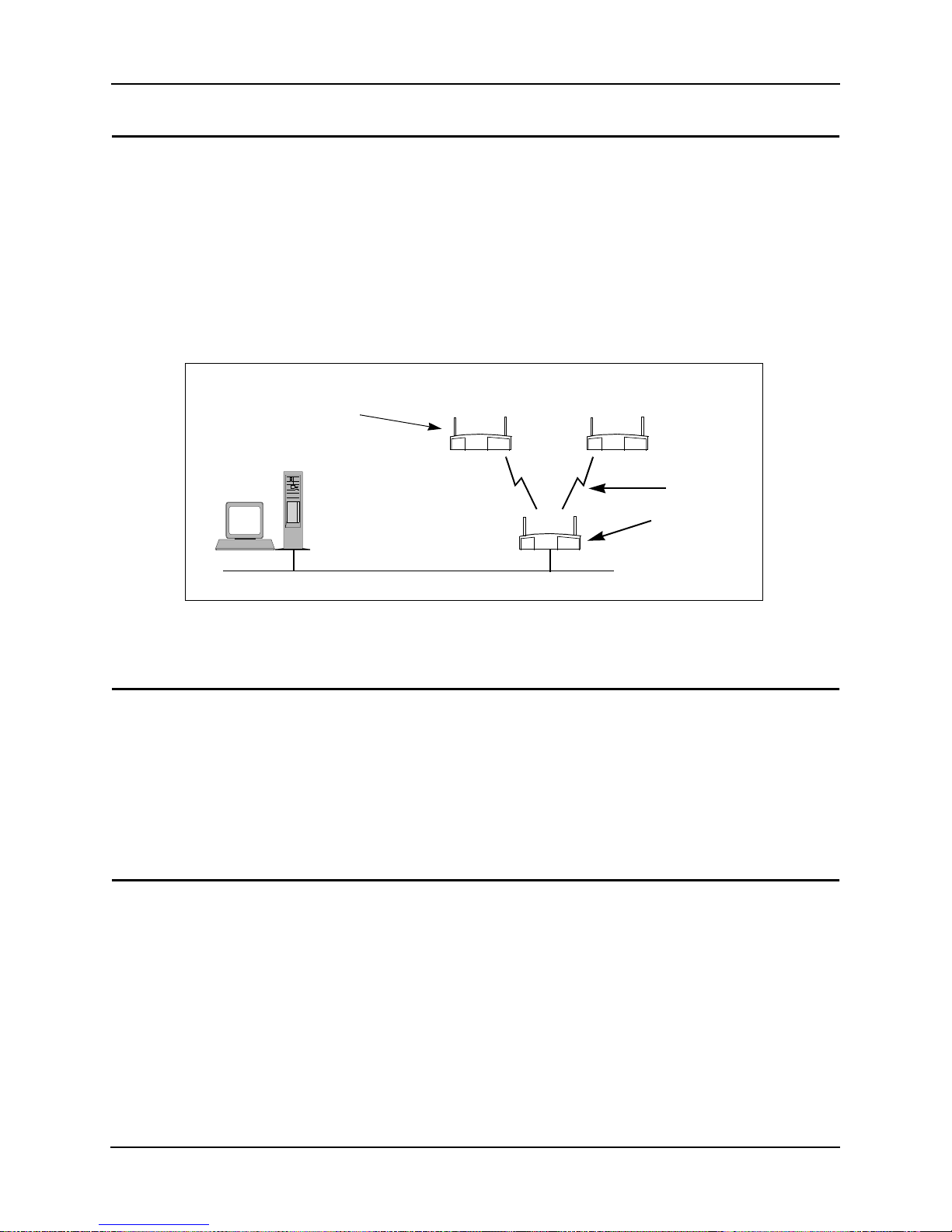
The basic settings for the access points are covered in the previous sections. In the following
network diagram examples, the root access point is labeled A, and the two designated WLAPs are
labeled B and C. For reference, the MAC addresses are included in the diagrams and example
screens.
HOST .CDR, FRA ME
WLAP Manual BSS ID
of B and C set to MAC
address of A
Host
Computer
00:A0:F8:8B:71:45 00:A0:F8:94:C3:64
B
C
One Hop
Root access point A
00:A0:F8:93:C5:B5
WLAP Priority = 7000
Ethernet
Figure 2-1: Wireless AP Network with One Hop
2.1 One-Hop Wireless Network Example
The example in Figure 2-1 extends a network’s radio coverage with one h op between the root
access point A and the two designated WLAPs B and C.
To configure the one-hop network, set the WLAP Manual BSS ID on the root access point to its
own MA C address. In addition, set the WLAP Manual BSS ID on access point B and C to the MAC
address of access point A. The RF Configuration screen for the root access point A is shown in
Figure 2-3.
2.2 Two-Hop Wireless Network Example
The example in Figure 2-2 e xtend s a netw ork’s radio coverage with two hops. In this network, there
is one hop between the root access point A and designated WLAP B, then another hop between
WLAP B and the other design ated WLAP C.
To configure a two-hop network, set the WLAP Manual BSS ID on access point C to the MAC
address of access point B and the WLAP Manual BSS ID on B to the MAC address of the root
access point A. The Manual BSS ID for the root access point A is set to its own MAC address. The
RF Configuration screen in Figure 2-3 shows the WLAP Manual BSS ID setting for access point C.
The RF Configuration screens for the other two access points are the same except the WLAP
Manual BSS IDs would be set to 00:A0:F8:93:C5:B5 and the WLAP Priority for access point A
would be set to 7000.
WLAP Manual
BSS ID of A set
to its own MAC
address.
4 Configuring Access Point Bridging and Repeating (WLAP Mode)
Page 11
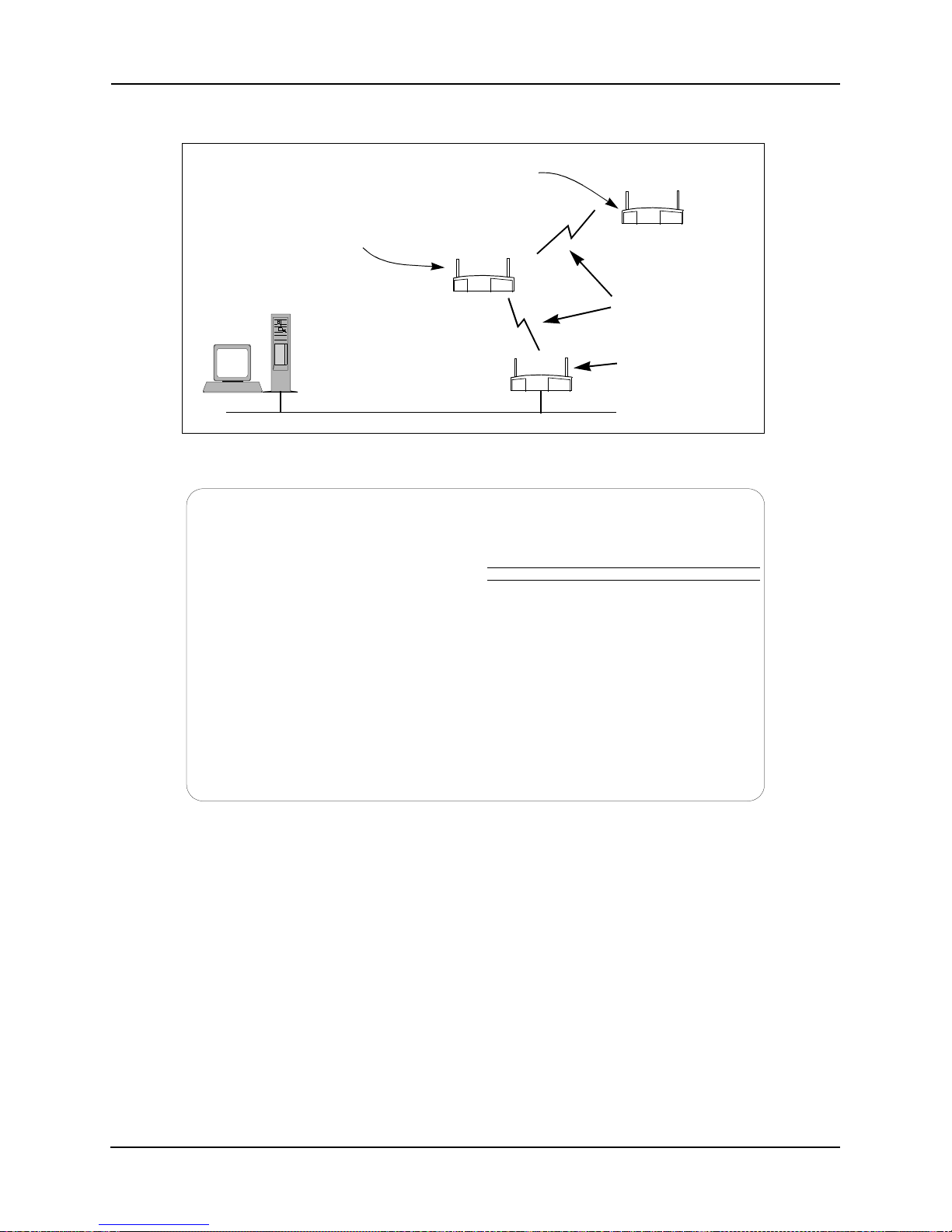
HOST .CDR, FRA ME
Chapter 2. Extending a Network’s Radio Coverage
WLAP Manual BSS ID set to
MAC address of access point B.
00:A0:F8:94:C3:64
WLAP Manual BSS ID
set to MAC address
of access po int A.
Host
Computer
00:A0:F8:8B:71:45
B
Root access point A
00:A0:F8:93:C5:B5
WLAP Priority = 7000
Ethernet
Two
Hops
WLAP Manual BSS
ID of A set to its own
MAC address.
Figure 2-2: Wireless AP Network with Two Hops
C
Access Point C
.DTIM Interval 10 WLAP Mode Enabled
.BC/MC Q Max 10
.Max Retries (d) 15 WLAP Priority 8000 hex
.Max Retries (v) 5 WLAP Manual BSS ID 00:A0:F8:8B:71:45
.Multicast Mask (d) 09000E00 hex
.Multicast Mask (v) 01005E00 hex WLAP Hello Time 20
.Beacon Interval 100 K-us WLAP Max Age 100
.Accept Broadcast ESSID Disabled WLAP Forward Delay 5
.MU Inactivity Timeout 60 min. WLAP MU Table Aging Time 240 min.
.Rate Control
11 Mb/s Optional .WEP (Privacy) Disabled
5.5 Mb/s Optional .WEP Algorithm 40 bit shared key
2 Mb/s Required .Encryption Key ID 1
1 Mb/s Required Encryption Key Maintenance
.RTS Threshold 2347 bytes
Extended Range 0 mi. Tx Power Control Full
RF Configuration
.Short RF Preamble Disabled
OK-[CR] Save-[F1] Save All APs-[F2] Cancel-[ESC]
Enter the desired WLAP MAC addr, with which this AP is going to associate.
Figure 2-3: WLAP Manual BSS ID on Access Point C in 2-Hop Network
Configuring Access Point Bridging and Repeating (WLAP Mode) 5
Page 12

Chapter 3. Verifying Wireless AP Operations
Chapter 3. Verifying Wireless AP Operations
You can verify wireless AP operations by looking at the following screens:
• WLAP RF Statistics
• Known Access Points
3.1 Viewing the WLAP RF Statistics Screen
Verify the wireless AP operations by viewing the WLAP RF Statistics screen. To view this screen,
Show RF Statistics from the access point’s Main Menu, then press Enter. This displays the
select
RF Statistics screen.
From the RF Statistics screen, press
is shown in Figure 3-1.
During a wireless AP operation, associated access points are listed on the WLAP RF Statistics
screen. The example screen in Figure 3-1 shows that two designated WLAPs have made wireless
links with the root access point. This screen is for the one-hop network example in Figure 3-1.
Notice that the two MAC addresses are listed under the “WLAP Itf Mac Addr” heading and two
FWD states are listed under the “Itf State” heading. The term FWD indicates the forwarding of data
to the associated access point.
For a two-hop network, the statistics in the WLAP RF Statistics screen is shown in Figure 3-2. The
WLAP RF Statistics screen for the root access point lists only one designated WLAP in the FWD
state. However, the WLAP B lists both of the other two access points in the FWD state.
Other possible “Itf” states on the WLAP RF Statistics screen are:
F3. This displays the WLAP RF Statistics screen. An example
Itf State Definition
DIS Wireless interface is disabled
LIS Access point is listening for configuration information
LRN Access point is learning the configuration information
FWD Access point is forwarding data
BLK Access point is blocking data
Table 3-1: Itf States
As an access point starts to associate in the wireless AP mode, the state changes from DI S to LIS to
LRN and then finally to FWD indicating association is successful.
Also note that in the example WLAP RF Statistics screens in Figure 3-1 and Figure 3-2, the Current
State entry is Functional, which means that the access point is ready for other access points to
associate with it. However, Functional does not necessarily mean that it has made a wireless AP
connection. Additional information is covered in the section titled 3.3.1: Functional State.
6 Configuring Access Point Bridging and Repeating (WLAP Mode)
Page 13

Access Point A
WLAP RF Statistics
Current # WLAP Itf 2 Root Interface 0
Current State Functional Root MAC Addr 00:A0:F8:93:C5:B5
Priority 7000 hex Root Path Cost 0
------------- Wireless AP Interface Table ---------------
Itf WLAP Itf Itf Path Designated Designated
ID MAC Addr State Cost Root ID Cost WLAP ID Itf ID
8001 00:A0:F8:8B:71:45 FWD 1 700000a0f893C5B5 0 700000a0f893C5B5 8001
8002 00:A0:F8:94:C3:64 FWD 1 700000a0f893C5B5 0 700000a0f893C5B5 8002
8003 00:00:00:00:00:00 DIS 1 700000a0f893C5B5 0 700000a0f893C5B5 8003
8004 00:00:00:00:00:00 DIS 1 700000a0f893C5B5 0 700000a0f893C5B5 8004
Refresh-[F1] Timed-[F2] Previous-[F4] Exit-[ESC]
Root Priority 7000 hex
Figure 3-1: RF Statistics from Root Access Point in One-Hop Network
Access Point B
Current # WLAP Itf 2 Root Interface 1
Current State Functional Root MAC Addr 00:A0:F8:93:C5:B5
Priority 8000 hex Root Path Cost 1
------------- Wireless AP Interface Table ---------------
WLAP RF Statistics
Root Priority 7000 hex
Itf WLAP Itf Itf Path Designated Designated
ID MAC Addr State Cost Root ID Cost WLAP ID Itf ID
8001 00:A0:F8:93:C5:B5 FWD 1 700000a0f893C5B5 0 700000a0f893C5B5 8001
8002 00:A0:F8:94:C3:64 FWD 1 700000a0f893C5B5 1 800000a0f88b7145 8002
8003 00:00:00:00:00:00 DIS 1 800000a0f88b7145 0 800000a0f88b7145 8003
8004 00:00:00:00:00:00 DIS 1 800000a0f88b7145 0 800000a0f88b7145 8004
Refresh-[F1] Timed-[F2] Previous-[F4] Exit-[ESC]
Figure 3-2: RF Statistics from Access Point B in Two-Hop Network
3.2 Viewing the Known Access Points Screen
The Known Access Points screen lists all access points that are linked together either through a
wireless connection or through a wired connection. You can use the Known Access Points screen to
determine the number of access points in a wireless AP network; however, keep in mind that the
screen also lists access points that are connected to the same Ethernet as the root access point but
may not be part of the wireless AP operation.
Figure 3-3 is an example of a Known Access Points screen listing the root access point and the two
designated WLAPs. This example screen includes another access point connected to the same
Ethernet as the root access point but not in the wireless AP network.
Configuring Access Point Bridging and Repeating (WLAP Mode) 7
Page 14
Chapter 3. Verifying Wireless AP Operations
Access Point A Known Access Points
MAC Address IP Address CH HST HSQ MUS KBIOS FW_Ver Away
00:A0:F8:93:C5:B5 157.235.55.199 3 - - 0 0 02.51-11
00:A0:F8:8B:71:45 157.235.55.60 1 - - 0 0 02.51-11
00:A0:F8:94:C3:64 157.235.55.198 11 - - 0 0 02.51-11
00:A0:F8:94:C2:04 157.235.55.53 1 - - 0 0 02.51-11
Echo-[F1] Delete-[F2] Next-[F3] Previous-[F4] Switch Exit-[ESC]
Figure 3-3: Known Access Points Showing WLAPs Plus Other
With this screen displayed, you can run an echo test, which performs a PING operation between the
current access point and any of the listed radio-or wired-linked access points. To do this, you use
Tab key to highlight the access point you wish to PING. Then press F1, followed by the Enter
the
key to start the echo test.
Net_ID: Warehouse 1
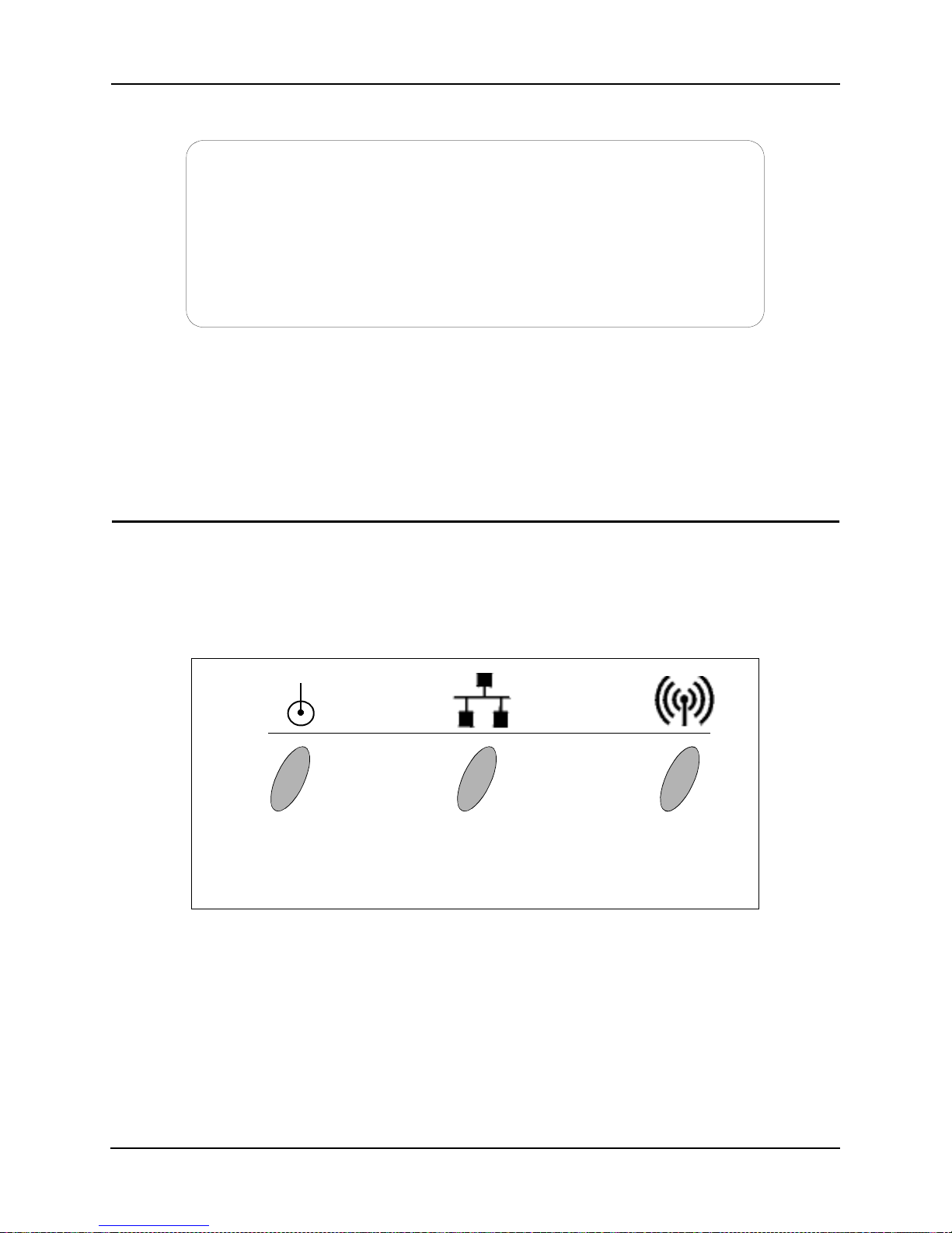
3.3 Observing the Access Point’s LED Indicators
The access point’s LED indicators and their basic functions are shown in Figure 3-4.
As an access point proceeds through the various states of a wireless AP operation, the LEDs
provide certain status indications. The Intel® PRO/Wireless 2011/2011B LAN Product Reference
Guides describe how the LED indicators are displayed during the several wireless AP operating
states from Initializing through Functional.
ICON GIF
FILES &
FRAME
Power
Flashes during pow er-up
sequence (reset).
Continuously on during
operation.
Wired LAN Activity
Flashes when data is
transferred on wired
network.
Figure 3-4: Access Point LED Indicators and Functions
Wireless LAN Activity
Flickers when access point
sends out beacon signals ,
and transfers data to and
from a mobile unit.
During normal operation, it may be difficult to observe the LED indicator status because the states
exists for only a very short time. During an abnormal operation, the access point may remain in a
particular state permanently or for a significant length of time. In this situation, you can easily
determine abnormal operation from the status of the LED indicators.
The following subsections cover two of the wireless AP states that you can easily determine by
observing the LED indicators. These two states are: Functional and Send Probe. One of thes e states
is displayed as the Current State entry on the WLAP RF Statistics screen.
8 Configuring Access Point Bridging and Repeating (WLAP Mode)
Page 15

Example screens showing the Current State as “Functional” are shown in Figure 3-1 and Figure 3-
2. An example screen showing the Current State as “Send Probe” is shown in Figure 3-5.
Access Point A
Current # WLAP Itf 0 Root Interface 0
Current State Send Probe
Priority 8000 hex Root Path Cost 0
------------- Wireless AP Interface Table ---------------
Itf WLAP Itf Itf Path Designated Designated
ID MAC Addr State Cost Root ID Cost WLAP ID Itf ID
8001 00:00:00:00:00:00 DIS 1 800000a0f893C5B5 0 800000a0f893C5B5 8001
8002 00:00:00:00:00:00 DIS 1 800000a0f893C5B5 0 800000a0f893C5B5 8002
8003 00:00:00:00:00:00 DIS 1 800000a0f893C5B5 0 800000a0f893C5B5 8003
8004 00:00:00:00:00:00 DIS 1 800000a0f893C5B5 0 800000a0f893C5B5 8004
Refresh-[F1] Timed-[F2] Previous-[F4] Exit-[ESC]
Figure 3-5: Access Point in the Send Probe State
3.3.1 Functional State
The Functional state means that the access point is ready for mobile units or other access points to
associate with it. In this state, the LED indicators display as follows:
Indicator Activity
Power Remains on
Wired LAN Activity Flashes if activity occurs
Wireless LAN Activity Flickers rapidly
WLAP RF Statistics
Root Priority 8000 hex
Root MAC Addr 00:A0:F8:93:C5:B5
Table 3-2: LED Indicators - Functional State
When the access point is in the Functional state, it may or may not have successfully made a
wireless AP connection. You can determine if a wireless AP connection has occurred by viewing
the WLAP RF Statistic screen. If this screen lists one or more access points as being in the FWD
state in the Itf State column, then the current access point has made a wireless AP connection. For
examples of screens showing the FWD state, refer to Figure 3-1 and Figure 3-2.
3.3.2 Send Probe State
Under certain conditions, an access point may remain in the Send Probe state (Figure 3-5) rather
than continue on to the Functional state. In this state, the LED indicators display as follows:
Indicator Activity
Power Remains on
Wired LAN Activity Remains off
Wireless LAN Activity Blinks slowly (once per second)
Configuring Access Point Bridging and Repeating (WLAP Mode) 9
Page 16

Chapter 3. Verifying Wireless AP Operations
Table 3-3: LED Indicators - Send Probe State
This occurs when an access point is configured to run in a wireless AP operation but is not
associating with any other access points. The access point remains in the Send Probe state under
one of the following conditions:
a. The access point’s WLAP Mode is set to
MAC address of another access point.
b. The access point’s WLAP Mode is set to Link Required, it has no Ethernet connection, and its
WLAP Manual BSS ID is set to either the zero default or another access po int’s MAC address.
The LED indicators continue to display the Send Probe status until association with another access
point occurs, at which time the access point goes to the Functional state.
Preferred MAC Address. For condition a, if the WLAP Manual BSS ID is set to a “preferred”
MAC address, the access point remains in the Send Probe state for approximately 30 seconds and
then goes to the Functional state. To enter a preferred MAC address, change the first two numbers
of the MAC address from 00 to 01; for example, 01:A0:F8:93:C6:E4. This is sometimes referred to
as turning on the broadcast bit.
No MAC Address. For condition a, if the WLAP Manual BSS ID is set to the zero default value, the
access point remains in the Send Probe state for approximately 30 seconds and then goes to the
Functional state.
Ethernet Connection. For condition b, the Etherne t connection mu st be restor ed befo re the access
point can associate and go to the Functional state.
Enabled and its WLAP Manual BSS ID is set to the
10 Configuring Access Point Bridging and Repeating (WLAP Mode)
Page 17

Chapter 4. Using the Link Required Option
As shown in Figure 4-1, Link Required is one of the options for the WLAP Mode entry on th e RF
Configuration screen. This option allows an access point to create a wireless link in the event it
loses its Ethernet connection.
Link Required can also be used to allow WLAPs to roam to another root access po int if the original
root access point loses its Ethernet connection.
Network examples using the Link Required option are covered in the following subsections.
Chapter 4. Using the Link Required Option
Access Point A
.DTIM Interval 10 WLAP Mode Link Required
.BC/MC Q Max 10
.Max Retries (d) 15 WLAP Priority 8000 hex
.Max Retries (v) 5 WLAP Manual BSS ID 00:00:00:00:00:00
.Multicast Mask (d) 09000E00 hex
.Multicast Mask (v) 01005E00 hex WLAP Hello Time 20
.Beacon Interval 100 K-us WLAP Max Age 100
.Accept Broadcast ESSID Disabled WLAP Forward Delay 5
.MU Inactivity Timeout 60 min. WLAP MU Table Aging Time 240 min.
.Rate Control
11 Mb/s Optional .WEP (Privacy) Disabled
5.5 Mb/s Optional .WEP Algorithm 40 bit shared key
2 Mb/s Required .Encryption Key ID 1
1 Mb/s Required Encryption Key Maintenance
.RTS Threshold 2347 bytes
Extended Range 0 mi. Tx Power Control Full
OK-[CR] Save-[F1] Save All APs-[F2] Cancel-[ESC]
Use the space bar to enable/disable/set link required WLAP operation.
RF Configuration
.Short RF Preamble Disabled
Figure 4-1: Setting the WLAP Mode to Link Required
4.1 Link Required for Maintaining Ethernet Link
As previously mentioned, the Link Required option allo ws an access point to oper ate as a WLAP if
it loses its Ethernet connection.
An example network is sho wn in Figu re 4-2. In this e xample, when access poin t B loses its Ethernet
connection, it resets then makes a wireless link to the Ethernet through access point A.
Configuring Access Point Bridging and Repeating (WLAP Mode) 11
Page 18

Chapter 4. Using the Link Required Option
A
Ethernet
Settings on Both Access Points:
WLAP Mode = Link Required.
WLAP Priority = 8000.
WLAP Manual BSS ID = 0.
Ethernet Timeout = 0.
A
Ethernet
If an access point loses its Ethernet connection, it rese ts and makes
a wireless link to the Ethernet through the other access point.
B
B
Figure 4-2: Link Required Operation for Maintaining Ethernet Link
By viewing the WLAP RF Statistics screen, you can determine whether or not a wireless link exists
between access points. In the example network in Figure 4-2, no wireless link exists between the
access points as long as they are both connected to the Ethernet. For this condition, the WLAP RF
Statistics screen (Figure 4-3) shows the Current State as Functional, the Itf State as DIS (disabled),
and the WLAP Itf MAC Addr as zero.
If one of the access points in the network in Figure 4-2 loses its Ethernet connection, it resets and
initiates a wireless connection with the other access point. When the process of making the wireless
link is completed, the WLAP RF Statistics screen (Figure 4-4) shows the Itf State as FWD
(forward) and the WLAP Itf MAC Addr as the MAC address of the other access point.
12 Configuring Access Point Bridging and Repeating (WLAP Mode)
Page 19

Chapter 4. Using the Link Required Option
Access Point A
Current # WLAP Itf 0 Root Interface 0
Current State Functional Root MAC Addr 00:A0:F8:93:C5:B5
Priority 8000 hex Root Path Cost 0
------------- Wireless AP Interface Table ---------------
Itf WLAP Itf Itf Path Designated Designated
ID MAC Addr State Cost Root ID Cost WLAP ID Itf ID
8001 00:00:00:00:00:00 DIS 1 800000a0f893C5B5 0 800000a0f893C5B5 8001
8002 00:00:00:00:00:00 DIS 1 800000a0f893C5B5 0 800000a0f893C5B5 8002
8003 00:00:00:00:00:00 DIS 1 800000a0f893C5B5 0 800000a0f893C5B5 8003
8004 00:00:00:00:00:00 DIS 1 800000a0f893C5B5 0 800000a0f893C5B5 8004
Refresh-[F1] Timed-[F2] Previous-[F4] Exit-[ESC]
WLAP RF Statistics
Root Priority 8000 hex
Figure 4-3: No Wireless Link With Proper Ethernet Connections
Access Point A
Current # WLAP Itf 1 Root Interface 1
Current State Functional Root MAC Addr 00:A0:F8:8B:71:45
Priority 8000 hex Root Path Cost 1
WLAP RF Statistics
Root Priority 8000 hex
------------- Wireless AP Interface Table ---------------
Itf WLAP Itf Itf Path Designated Designated
ID MAC Addr State Cost Root ID Cost WLAP ID Itf ID
8001 00:A0:F8:8B:71:45 FWD 1 800000a0f88b7145 0 800000a0f88b7145 8001
8002 00:00:00:00:00:00 DIS 1 800000a0f893C5B5 0 800000a0f893C5B5 8002
8003 00:00:00:00:00:00 DIS 1 800000a0f893C5B5 0 800000a0f893C5B5 8003
8004 00:00:00:00:00:00 DIS 1 800000a0f893C5B5 0 800000a0f893C5B5 8004
Refresh-[F1] Timed-[F2] Previous-[F4] Exit-[ESC]
Figure 4-4: Wireless Link After Loss of Ethernet Connection
4.2 Link Required for Backing Up Root Access Point
This section shows how to use the Link Required option so that designated WLAPs can roam to
another root access point if the original one loses its Ethernet connection. In Figure 4-5, access
points B and C are initially the designated WLAPs for root access point A. When access point A’s
Ethernet connection is broken, access points B and C reset then to roam to access point D.
Furthermore, if access point D loses its Ethernet connection and access point A’s Ethernet
connection is restored, WLAPs B and C roams back to access point A.
Configuring Access Point Bridging and Repeating (WLAP Mode) 13
Page 20

Chapter 4. Using the Link Required Option
WLAP Mode = Link Required.
WLAP Priority = 8000.
WLAP Manual BSS ID set to access
point A’s preferred MAC address
(01:A0:F8:93:C5:B5).
Ethernet Timeout = 0.
B
WLAP Mode = Enabled.
WLAP Priority = 7000.
WLAP Manual BSS ID set to its own
MAC address (00:A0:F8:93:C5:B5).
Ethernet Timeout = 1.
FRAME
C
A
Ethernet
WLAP Mode = Enabled.
WLAP Priority = 6000.
WLAP Manual BSS ID set to its
own MAC address.
Ethernet Timeout = 1.
If Ethernet connection is
lost, access point D becomes
new root access point.
D
Figure 4-5: Network with Backup Root Access Point
Access point settings for the example in Figure 4-5 are described as follows:
Basic Settings. Make the settings previously described in 1.1: Basic Settings for Access Points.
WLAP Mode on RF Conf iguration Screen. On design ated WLAPs B and C, s et the WLAP Mode to
Link Required. This causes the WLAPs to search for another access point with an Ethernet
connection in the even t the ro ot acces s poin t loses its Ethern et connection. W LAP Mode for access
points A and D is set to Enabled.
WLAP Priority on RF Configur ation Screen. On access point A, mak e sure its W LAP Priority is set
to a lower number (e.g., 7000) than the two WLAPs. On access point D, make sure its WLAP
Priority is set to a lower number (e.g., 6000) than the other access points. The lower priority
number ensures that access point D is recognized as the new root access point in the event access
point A loses its Ethernet connection.
WLAP Manual BSS ID on RF Configuration Screen. On designated WLAPs B and C, set the
WLAP Manual BSS ID to the “preferred” MAC address of the root access point A. To enter a
preferred MAC address, change the first two numbers of the MAC address from 00 to 01; for
example, 01:A0:F8:8D:25:F2. Using a preferred MAC address not only causes WLAPs B and C to
associate with the root access point A, it also allows them to roam to another access point if the
Ethernet connection to access point A is lost.
Ethernet Timeout on System Configuration Screen. Set the Ethernet Timeout to 1 on the two
access points connected to the Ethernet (access points A and D). On WLAPs B and C, set the
Ethernet Timeout to the default value of 0. With its Timeout set to 1, access point A detects a
broken Ethernet connection and turns off its radio to allow the desi gnated WLAPs B and C to
search for another access point (e.g., access point D). Likewise, if access point D becomes the root,
it would perform in the same way if it loses its Ethernet connection. An example System
Configuration screen is shown in Figure 4-6.
14 Configuring Access Point Bridging and Repeating (WLAP Mode)
Page 21

Channel Setting. For wireless AP operations, it is not necessary to make any changes to the
Channel setting. Designated WLAPs normally adopt the channel number of the root access point
instead of using their own ch annel n umbers specified on the System Configuration screen. To view
the adopted channel number, refer to the System Summary screen.
Access Point A
Channel 3 .Access Control Disabled
Auto Channel Select Disabled .Type Filtering Disabled
.Ethernet Timeout 1
.Telnet Logins Enabled .AP-AP State Xchg Enabled
.Encryption Admin Any Ethernet Interface On
.Agent Ad Interval 0 Default Interface
.S24 Mobile IP Disabled Ethernet
.Mobile-Home MD5 key *******
.Web Server Enabled
Configure Kerberos-[F3] .Inactivity Timeout 5
System Password Admin-[F4]
OK-[CR] Save-[F1] Save All APs-[F2] Cancel-[ESC]
Sftwr detect(30-255 secs), 2,3,4 WLAP detect, 1 hardware detect, 0 disable
System Configuration
WNMP Functions Enabled
RF Interface On
.MU-MU Disallowed Off
.Modem Connected No
Figure 4-6: Setting the Ethernet Timeout to 1
Configuring Access Point Bridging and Repeating (WLAP Mode) 15
Page 22

Chapter 5. Bridging Two Ethernet Networks
Chapter 5. Bridging Two Ethernet Networks
As mentioned previously, you can use the wireless AP bridging feature to obtain a wireless
connection between two Ethernet networks. An example of this is shown in Figure 5-1.
HOST.CDR, FRAME
C
00:A0:F8:94:C3:64
WLAP Mode
Disabled
Ethernet
Host Computer
Wireless Link
A
00:A0:F8:93:C5:B5
WLAP Mode Enabled.
WLAP Manual BSS ID
set to MAC ad dress of
root access point B.
Root
B
00:A0:F8:8B:71:45
WLAP Mode Enabled.
WLAP Manual BSS ID
set to its own
MAC address
D
00:A0:F8:94:C2:04
WLAP Mode
Disabled
Ethernet
Host Computer
Figure 5-1: Bridging Two Ethernet Networks with Wireless AP
In the example, access points A and B hav e their WLAP Mode set to
Enabled and provide the link
between the two Ethernet networks. The WLAP Manual BSS ID for access point A is set to the
MAC address of root access po int B. The WLAP Manual BSS ID for root access point B is set to its
own MAC address. Access point B is the root access point because its MAC address
(00:A0:F8:8B:71:45) is lower than that of access point A (00:A0:F8:93:C5:B5). The WLAP
Priority for these access points is set to the default value, 8000.
Also, in the example, all access points have their Ethernet Timeout set to the default value of zero,
and access points C and D have their WLAP Mode disabled.
5.1 V erifying the Bridging Operation
As in the oth er wireless AP configurations, you can verif y the network bridging operating by
viewing the WLAP RF Statistics screen and the Known Access Points screen.
To determine which access points are operating in the wireless AP mode, view the WLAP RF
Statistics screen. The example screen in Figure 5-2 shows access point A with a Current State of
Functional and the forwarding of data (FWD) to the MAC address of access point B. Likewise, the
screen viewed on access point B w ould show the forwarding of data to access point A. This verifies
the wireless link between the two Ethernet networks in the example of Figure 5-1.
16 Configuring Access Point Bridging and Repeating (WLAP Mode)
Page 23

Because the other two access points C and D have their WLAP Mode disabled, their WLAP RF
Statistics screen shows the Current State as Disabled and the Itf State as DIS (disabled).
Access Point A
Current # WLAP Itf 1 Root Interface 1
Current State Functional Root MAC Addr 00:A0:F8:8B:71:45
Priority 8000 hex Root Path Cost 1
------------- Wireless AP Interface Table ---------------
Itf WLAP Itf Itf Path Designated Designated
ID MAC Addr State Cost Root ID Cost WLAP ID Itf ID
8001 00:A0:F8:8B:71:45 FWD 1 800000a0f88b7145 0 800000a0f88b7145 8001
8002 00:00:00:00:00:00 DIS 1 800000a0f893C5B5 0 800000a0f893C5B5 8002
8003 00:00:00:00:00:00 DIS 1 800000a0f893C5B5 0 800000a0f893C5B5 8003
8004 00:00:00:00:00:00 DIS 1 800000a0f893C5B5 0 800000a0f893C5B5 8004
Refresh-[F1] Timed-[F2] Previous-[F4] Exit-[ESC]
WLAP RF Statistics
Root Priority 8000 hex
Figure 5-2: Verifying Wireless AP for Bridging Networks
From any of the access points, you can view the Known Access Points screen to verify that all
access points are linked together through the wired and wireless connections. With a successful
bridging operation, the screen lists all access points on both Ethernet networks. Figure 5-3 is an
example screen showing all four access points in the network of Figure 5-1.
Access Point D Known Access Points
MAC Address IP Address CH HST HSQ MUS KBIOS FW_Ver Away
00:A0:F8:94:C2:04 157.235.55.53 1 - - 0 0 02.51-11
00:A0:F8:93:C5:B5 157.235.55.199 3 - - 1 0 02.51-11
00:A0:F8:8B:71:45 157.235.55.60 1 - - 0 0 02.51-11
00:A0:F8:94:C3:64 157.235.55.198 11 - - 0 0 02.51-11
Net_ID: Warehouse 1
Echo-[F1] Delete-[F2] Next-[F3] Previous-[F4] Switch Exit-[ESC]
Figure 5-3: Viewing the Access Points in Bridged Networks
5.2 Using the Ethernet Timeout Settings 2 & 3
Ethernet Timeout settings 2 and 3 on System Configuration screen are used in special network
configurations such as the one shown in Figure 5-4. In this network, if access point A loses its
Ethernet connection, mobile units are able to roam from access point D to access point H.
The following subsections describe the access point settings and sequence of events for the special
network.
Configuring Access Point Bridging and Repeating (WLAP Mode) 17
Page 24

Chapter 5. Bridging Two Ethernet Networks
FRAME
D
C
B
A
Timeout = 0
10BaseT Cross-Over
Timeout = 3
Timeout = 2
Timeout = 1
Mobile unit ro ams to access
point H if access poi nt A loses
Ethernet co nnecti on.
H
Timeout = 0
Cables (Figure 5-5)
G
Timeout = 3
F
Timeout = 2
E
Timeout = 1
Ethernet
Figure 5-4: Special Network Using Timeout Settings 2 & 3
5.2.1 Ethernet Timeouts and Access Point Settings
This section describes the Ethernet Timeout settings and other access point settings for the special
network in Figure 5-4. Ethernet Timeout settings, seen on the System Configuration screen,
include:
Setting Description
Timeout = 0 Ethernet Timeout function is disabled.
Timeout = 1 Access point detects a broken Ethernet connection and then turns
off its radio.. The Wireless LAN Activity indicator turns off.
When the Ethernet connection is restored, the radio is turned on
again.
Timeout = 2 Access point sends WLAP-Alive BPDU messages on the
Ethernet line as well as over wireless network. This allows other
access points on the same Ethernet line to detect its presence.
18 Configuring Access Point Bridging and Repeating (WLAP Mode)
Page 25

Timeout = 3 Access point monitors WLAP-Alive BPDU messages on the
Ethernet line as well as over the wireless network. If the BPDU
message is missing on the Ethernet line, the access point turns off
its radio and flashes its Ethernet Activity indicator approximately
once every second. The BPDU is considered missing after a
certain time determined by the setting of the WLAP Hello Time
on the RF Configuration screen. The def ault is 20 second s. When
the Ethernet connection is restored, the access point turns on its
radio and stops flashing the LED indicator.
Timeout = 4 Access point monitors WLAP-Alive BPDU messages on the
Ethernet line as well as over the wireless network. If the BPDU
message is missing on the Ethernet line, the access point resets.
An example network using this setting is described in 5.3: Using
the Ethernet Timeout Setting 4.
Table 5-1: Ethernet Timeout Settings
The wiring diagram for an Ethernet 10BaseT cross-over cable is shown in Figure 5-5.
The following are the settings for the access points in the special network of Figure 5-4. All access
points have the WLAP Mode set to
Enabled.
Access Point A. Timeout = 1
Priority = 7000
WLAP Manual BSS ID = its own MAC address
Access Point B. Timeout = 2
Priority = 8000 (default)
WLAP Manual BSS ID = MAC address of access point A
Access Point C. Timeout = 3
Priority = 8000 (default)
WLAP Manual BSS ID = its own MAC address
Access Point D. Timeout = 0
Priority = 9000
WLAP Manual BSS ID = MAC address of access point C
Access Point E. Timeout = 1
Priority = 7000
WLAP Manual BSS ID = its own MAC address
Access Point F. Timeout = 2
Priority = 8000 (default)
WLAP Manual BSS ID = MAC address of access point E
Access Point G. Timeout = 3
Priority = 8000 (default)
WLAP Manual BSS ID = its own MAC address
Access Point H. Timeout = 0
Priority = 9000
WLAP Manual BSS ID = MAC address of access point G
Configuring Access Point Bridging and Repeating (WLAP Mode) 19
Page 26

Chapter 5. Bridging Two Ethernet Networks
5.2.2 Sequence of Events in Special Network
In the example network in Figure 5-4 , the following ev ents occur if access point A loses its Ethernet
connection:
• Access point A loses its Ethernet connection then turns off its radio.
• Access point B loses the beacon message from access point A, but it keeps probing access
point A (Send Probe state).
• Access Point B then stops sending the WLAP-Alive-BPDU message on the cross-over
Ethernet cable.
• Access Point C loses the WLAP-Alive-BPDU message then turns off its radio. The Ethernet
Activity LED indicator flashes appro ximately o nce every second until the Ethernet connection
is restored. With a lost Ethernet connection, the WLAP RF Statistics screen displays the
Current State as “WLAP Lost on Ethernet” and the Wireless Interface (Itf) State as data
blocked (BL K). An example screen is shown in Figure 5-6.
• Access Point D loses the beacon message from access point C, but keeps probing access point
C (Send Probe state).
• Mobile unit loses beacon message from access point D, then roams to access point H.
Transmit+
Transmit–
Receive+
Receive–
1
2
3
6
1
Transmit+
2
Transmit–
3
Receive+
6
Receive–
Pins 4, 5, 7 and 8 are not used.
Figure 5-5: Wiring Connections of Cross-Over 10BaseT Cable
Access Point C
Current # WLAP Itf 1 Root Interface 0
Current State WLAP Lost on Ethernet Root MAC Addr 00:A0:F8:94:C3:64
Priority 8000 hex Root Path Cost 0
------------- Wireless AP Interface Table ---------------
Itf WLAP Itf Itf Path Designated Designated
ID MAC Addr State Cost Root ID Cost WLAP ID Itf ID
8001 00:A0:F8:94:C2:04 BLK 1 800000a0f894C364 0 800000a0f894C364 8001
8002 00:00:00:00:00:00 DIS 1 800000a0f894C364 0 800000a0f894C364 8002
8003 00:00:00:00:00:00 DIS 1 800000a0f894C364 0 800000a0f894C364 8003
8004 00:00:00:00:00:00 DIS 1 800000a0f894C364 0 800000a0f894C364 8004
WLAP RF Statistics
Root Priority 8000 hex
Refresh-[F1] Timed-[F2] Previous-[F4] Exit-[ESC]
Figure 5-6: States of Access Point C with Timeout 3 & Lost Ethernet
20 Configuring Access Point Bridging and Repeating (WLAP Mode)
Page 27

5.3 Using the Ethernet Timeout Setting 4
Ethernet Timeout setting 4 on System Configuration screen is used in special network
configurations such as the one shown in Figure 5-7. In this network, the Timeout setting 4 allows
access point B to detect a missing WLAP-Alive BPDU message if the Ethernet connection is lost
between the two network hubs. When this occurs, access point B resets and makes a wireless
connection with access point A. If the Ethernet connection is restored, access point B resets and the
wireless connection is terminated.
As shown in Figure 5-7, Ethernet Timeout is set to 2 for access point A and to 4 for access point B.
Both access points have the WLAP Mode set to Enabled, WLAP Priority set to 8000 (defau lt), and
WLAP Manual BSS ID set to zero (default).
FRAME
Hub 1
Ethernet Connection
Hub 2
A
Ethernet Timeout = 2
WLAP Mode = Enabled
WLAP Priority = 8000
WLAP Manual BSS ID = 0
Hub 1
Ethernet Connection is Lost
A
Wireless Connection is Made
Figure 5-7: Special Network Using Ethernet Timeout 4
B
Ethernet Timeout = 4
WLAP Mode = Enabled
WLAP Priority = 8000
WLAP Manual BSS ID = 0
Hub 2
B
Configuring Access Point Bridging and Repeating (WLAP Mode) 21
Page 28

Chapter 6. RF Link Test
RFLINKINTRO
WMF
Chapter 6. RF Link Test
The RF Link Test is a site survey tool primarily for testing RF transmissions between access points
used for bridging Ethernet networks. It can also be used for checking RF paths to mobile units.
The RF Link Test is only available with an Intel PRO/Wireless 2011 LAN Access Point that has
been upgraded with the latest firmware. To obtain the latest firmware, go to the Intel support
website.
The example in Figure 6-1 shows two access points providing a wireless bridge between buildings.
The RF Link Test tests the quality of the wireless link so that you can position the directional
antennas for optimum signal transmission. This operation is covered later in 6.6: Using RF Link
Test to Align Directional Antennas.
Directional Antenna Directional Antenna
Building A
Access Point
Portable
.
Computer
Figure 6-1: Example of Using RF Link Test for Antenna Positionin g
6.1 Basic Setup for the RF Link Test
The basic setup for running the RF Link Test is shown in Figure 6-2. It consists of tw o access points
communicating through a wireless access point link with on e access po int co nnected to a co mputer
through a serial connection. The RF Link Test displays a special screen called Connection Quality
Test that displays a bar graph showing the signal strength received from the remote access point.
The computer may also connect to the local access point through a Telnet connection. This is
covered in section 6.4.1: Running the RF Link Test with Telnet.
Building B
Access Point
Portable
Computer
22 Configuring Access Point Bridging and Repeating (WLAP Mode)
Page 29

6.2 The Connection Quality Test Screen
During the RF Link Test, the local access point sends Wireless Network Maintenance Protocol
(WNMP) packets once every second, and the signal quality of each reply is displayed on the
Connection Quality Test screen. An example is shown in Figure 6-2.
Descriptions of the items displayed on the Connection Quality Test screen are listed in Table 6-1.
Local Access Point
Connection Quality Test
Remote Device MAC Address: 00:A0:F8:94:C2:04
max |
|
|
|
Signal |
Quality |
|
|
|
min |
-------------------------------------------
Chapter 6. RF Link Test
Tx Rate 11 Mb/s Tx Retries 1
Rx Rate 11 Mb/s RSSI 22
Exit-[ESC]
Figure 6-2: Example of Connection Quality Test Screen
Item Definition
Remote Device MAC
Address
MAC address of the remote access point that has a wireless
access point link to the local access point.
Signal Quality Displayed as vertical bars. Each bar is the signal quality, or
strength, of each reply received from the remote access point.
The higher the bar, the better the signal quality.
Tx Rate Shows the transmitted data rate of the local access point in
Megabits per second Mbps. One of four rates may be
displayed: 11, 5.5, 2, or 1 Mbps.
Rx Rate Received data rate from remote access point in Mbps. One of
four rates may be displayed: 11, 5.5, 2, or 1 Mbps.
Tx Retries Number of times packets are retransmitted from the local
access point.
RSSI Received Signal Strength Indicator. Indicates the current
signal strength of the signal received from the remote access
point. The maximum RSSI value for this test is 31; although,
the RSSI scale during normal operation goes up to 255.
Table 6-1: Definitions of Connection Quality Test Screen
Configuring Access Point Bridging and Repeating (WLAP Mode) 23
Page 30

Chapter 6. RF Link Test
6.2.1 Low and Zero RSSI Readings
For RSSI values less than 3, the Connection Quality Test screen displays underscores ( _ ) instead
of bars. In addition, the screen displays the letter X to indicate that a reply is not being received
from the remote access point within the one-second interval. In this case, RSSI is zero. If the letter
X is continuously displayed, the access points may be either out of radio range or their wireless
access point link is broken. Fo r information on verifying the wireless access point operation, refer
to 6.3: Preparing for the RF Link Test. Figure 6-3 is an example of a screen showing the X’s and
underscores.
Local Access Point
Remote Device MAC Address: 00:A0:F8:94:C2:04
max |
|
|
|
Signal |
Quality |
|
|
|
min|xxxx_________________
------------------------------------------Tx Rate 1 Mb/s Tx Retries 13
Rx Rate 1 Mb/s RSSI 2
Connection Quality Test
Exit-[ESC]
Figure 6-3: Connection Quality Test Screen Showing Low RSSI
24 Configuring Access Point Bridging and Repeating (WLAP Mode)
Page 31

6.3 Preparing for the RF Link Test
Before attempting to run the RF Link Test, make sure the two access points are configured as
shown in 6.1: Basic Setup for the RF Link Test. Also make sure that they are communicating with
each other through a wireless connection. Verify the wireless access point operation by looking at
the access point’s WLAP RF Statistics screen. To do this, press
the WLAP RF Statistics screen displayed, verify that the Current State is Functional and the Itf
State is being forwarded (FWD) to the MAC address of the remo te access point. An ex ample of the
WLAP RF Statistics screen is shown in Figure 6-4.
Chapter 6. RF Link Test
F3 on the RF Statistics screen. With
Local Access Point
Current # WLAP Itf 1 Root Interface 0
Current State Functional Root MAC Addr 00:A0:F8:93:C5:B5
Priority 7000 hex Root Path Cost 0
------------- Wireless AP Interface Table ---------------
Itf WLAP Itf Itf Path Designated Designated
ID MAC Addr State Cost Root ID Cost WLAP ID Itf ID
8001 00:A0:F8:94:C2:04 FWD 1 700000a0f893C5B5 0 700000a0f893C5B5 8001
8002 00:00:00:00:00:00 DIS 1 700000a0f893C5B5 0 700000a0f893C5B5 8002
8003 00:00:00:00:00:00 DIS 1 700000a0f893C5B5 0 700000a0f893C5B5 8003
8004 00:00:00:00:00:00 DIS 1 700000a0f893C5B5 0 700000a0f893C5B5 8004
Refresh-[F1] Timed-[F2] Previous-[F4] Exit-[ESC]
Figure 6-4: Verifying the Wireless AP Operation
6.4 Running the RF Link Test
To run the RF Link Test:
1. Set up the two access points as described in the previous section.
2. From the access point Main menu, select
WLAP RF Statistics
Root Priority 7000 hex
Show RF Statistics.
Configuring Access Point Bridging and Repeating (WLAP Mode) 25
Page 32

Chapter 6. RF Link Test
3. With the RF Statistics screen displayed, pr ess F4. This display s th e Connection Quality Test
screen, as shown in Figure 6-5.
Local Access Point
Remote Device MAC Address: 00:00:00:00:00:00
Signal |
Quality |
Enter MAC Address to start test.
Connection Quality Test
max |
|
|
|
|
|
|
min |
-------------------------------------------
Tx Rate Mb/s Tx Retries
Rx Rate Mb/s RSSI
Exit-[ESC]
Figure 6-5: Connection Quality Screen Before Start of Test
4. Enter the MAC address of the remote access point.
5. Press
Enter to highlight the MAC address, then press Enter again to start the RF Link Test.
During the test, vertical bars scroll across the Connection Quality Test screen. As a new bar is
displayed, its signal strength number is displayed as the RSSI number at the bottom of the
screen. The higher the bar, the higher the RSSI number. Maximum signal strength is an RSSI
number of 31. An example screen showing the maximum signal strength is shown in Figure 6-
6.
6. To stop the RF Link Test, press the
Esc key. This returns you to the Main Menu.
26 Configuring Access Point Bridging and Repeating (WLAP Mode)
Page 33

Local Access Point
Connection Quality Test
Remote Device MAC Address: 00:A0:F8:94:C2:04
max |
|
|
|
Signal |
Quality |
|
|
|
min |
-------------------------------------------
Tx Rate 11 Mb/s Tx Retries 0
Rx Rate 11 Mb/s RSSI 31
Exit-[ESC]
Chapter 6. RF Link Test
Figure 6-6: Test Screen Showing Maximum Quality of 31
Some settings on the RF Configuration screen may also affect the RF Link Test. These settings are
described in 6.6.2: Procedure for Aligning Directional Antennas.
Local Access Point
MAC Addr: 00:A0:F8:93:C5:B5
Wireless AP Link
Portable Computer
Running the RF Link Test
Remote Access Point
MAC Addr: 00:A0:F8:94:C2:04
LAPTOPLITE2.CDR,
AP11MB3DSHADED.CDR
Figure 6-7: Basic Setup for RF Link Test
6.4.1 Running the RF Link Test with Telnet
For access point networks that are already installed, it may be more appropriate to run the RF Link
Test using a Telnet connection. In this case, you must connect the local access point and computer
running the RF Link Test to the same Ethernet network.
Configuring Access Point Bridging and Repeating (WLAP Mode) 27
Page 34

Chapter 6. RF Link Test
Make sure the Telnet Logins option is enabled on the local access point’s System Configura t i on
screen. In addition, make sure that the IP address and subnet mask of the computer are appropriate
for the network and access point.
An example Telnet setup is shown in Figure 6-8, and the associated RF Link Test screen shown in
Figure 6-9.
IP Address 157.235.55.199
MAC Addr: 00:A0:F8:93:C5:B5
IP Address 157.235.55.53
MAC Addr: 00:A0:F8:94:C2:04
Wireless AP Link
Ethernet Network
IP Address 157.235.55.50
Portable Computer
Running the RF Link Test
Figure 6-8: Running RF Link Test with Telnet Connection
LAPTOPLITE2.CDR,
AP11MB3DSHADED.CDR
28 Configuring Access Point Bridging and Repeating (WLAP Mode)
Page 35

Chapter 6. RF Link Test
Figure 6-9: Test Screen Example Using the Telnet C onnection
6.5 Using RF Link Test with Mobile Units
The RF Link Test may also be used to test the RF transmission paths to mobile units. In this case,
the access point does not have to be operating in the wireless access point mode. The only
requirements are that the mobile units have the same ESS ID as the access point and that they
support the WNMP.
Figure 6-10 shows an access point associating with mobile units. In this example, you can use the
RF Link Test to check the wireless path of a remote printer linked to a network through a client
bridge.
Configuring Access Point Bridging and Repeating (WLAP Mode) 29
Page 36

Chapter 6. RF Link Test
8
Local Access Point
Portable Computer
Running the RF Link Test
Printer
Client Bridge
00:A0:F8:30:D6:8
Portable Data Terminal
LAPTOPLITE2.CDR, AP11MB3DSHADED.CDR,
CB1000WITHPRNTR.WMF
Figure 6-10: Access Point Associating with Mobile Units
Before running the RF Link Test with a particular mobile unit, make sure the access point is
associating with the unit by viewing the access point’s Mobile Units screen. This screen is shown in
the example of Figure 6-11. To do this, select
Show Mobile Units from the Main menu. Once
association is verified, run the RF Link Test by entering the mobile unit’s MAC address in the
Connection Quality Test screen (Figure 6-6) as previously described.
Local Access Point
Mobile Units
00:A0:F8:30:D6:88 C:R11:N
00:A0:F8:85:DC:57 P:R11:N
Information-[CR] Echo-[F1] Timed-[F2] Next-[F3] Exit-[ESC]
Figure 6-11: Verifying Association of Mobile Units
6.6 Using RF Link Test to Align Directional Antennas
The RF Link Test is useful for aligning directional antennas connected to access points that are
used for bridging separate Ethernet networks located one-qu arter mile or more from each other. An
example setup for this type of operation is shown in Figure 6-12.
30 Configuring Access Point Bridging and Repeating (WLAP Mode)
Page 37

Chapter 6. RF Link Test
RFLINKSYS
WMF
Directional Antenna
on Roof of Building A
Directional Antenna
on Roof of Building B
Wireless AP Link
Antenna Cable
.
Access Point A
Computer with
Serial Cable
Access Point B
Computer with
Serial Cable
Antenna Cable
Figure 6-12: Example Setup for Using RF Link Test to Align Antennas
The alignment procedure is to point the antennas toward each other so that the RF Link Test for
each access point shows the maximum RSSI reading. The antenna positioning is further refined by
reducing the access point’s radio power, while maintaining the maximum RSSI reading.
Some access points support the radio power control feature; others do not support this feature.
This procedure is covered in the following subsections.
6.6.1 Setting Up for the Antenna Alignment Procedure
Follow these steps to set up the bridging access points. An example setup diagram is shown in
Figure 6-12.
1. Install th e directio nal antennas so that nothing obstructs the line of sight between them. For
best results, mount each antenna on a pole on an elevated location such as the roof of a
building. An example of a directional antenna is shown in Figure 6-13.
2. Connect the antenna cable to the access point’s Antenna 1 connector, sometimes referred to as
the Primary connector. As shown in Figure 6-14, this is the connector on the right as you face
the rear of the access point.
If the standard antenna cable is not long enough, use a special lo w-loss antenn a cable. The lo w-loss
antenna cable is custom made for a particular installation. It usually connects to the access point
through an adapter cable. Length of the low-loss cable may be up to 60 feet. Only site survey or
cable specialists should make custom antenna cables of this type.
Configuring Access Point Bridging and Repeating (WLAP Mode) 31
Page 38

Chapter 6. RF Link Test
YAGIAN T.WMF
Figure 6-13: Exampel of a Directional Antenna
3. Connect the access point to a computer through a serial cable and turn on the access point. The
DC power connector is shown in Figure 6-14.
4. With the Access Point Installation screen displayed on the computer, set the Antenna Selection
option to
Refer to the next subsection for the antenna alignment procedure.
Primary Only. Press F1 to save the setting, then reset the access point.
DSAPBOTCN2.WMF
Antenna 2
Connector
Serial Port
Connector
DC Power
Connector
Figure 6-14: Access Point Connectors
6.6.2 Procedure for Aligning Directional Antennas
After setting up the equipment, follow these steps for aligning directional antennas connected to the
bridging access points. At each location, a technician performs the procedure. Align one antenna
first, and then align the other. As the technicians position the antenna and run the RF Link Test,
they need to communicate with each other usi ng two-way radios or cell phones. Other equipment
you may need is covered in 6.6.3: Additional Suggestions on Antenna Alignment.
1. Attempt to point the antennas toward each other so that the access points communicate with
each other through a wireless access point operation. Information on verifying the wireless
access point operation is covered in 6.3: Preparing for the RF Link Test.
Antenna 1
Connector
2. Make sure the Rate Control on the RF Configurations screen is set to
rates (Figure 6-15). This is recommended for access points that are performing a bridging
function.
3. If antennas are over a mile apart, set the
the appropriate distance setting. Type in the closest whole number in miles that matches the
distance between antennas. This setting allows for the timing delays for distances over 1 mile.
32 Configuring Access Point Bridging and Repeating (WLAP Mode)
Required for all four
Extended Range on the RF Configuration screen to
Page 39

Chapter 6. RF Link Test
The maximum setting is 50 miles. The example screen in Figure 6-15 shows a setting of two
miles.
The Extended Range setting is only available with an Intel PRO/Wireless 2011 LAN Access Poin t
that has been upgraded with the latest firmware. To obtain the latest firmware, go to the Intel
support website.
4. Make sure the radio in each access point is set to full power. You can v erify this b y vie wing the
Tx Power Control setting on the RF Configuration screen (Figure 6-15).
After changing screen settings, remember to Press F1. Then, reset the access point.
5. Run the RF Link Test. If the access point’s RSSI reading is 31 (maximum), set the Tx Power
Control to 30 mW by pressing the space bar. This setting is supported by some radios only. If
both access points show an RSSI reading of 31, they should both have their radio power
reduced at the same time. After changing the power settings, remember to save the setting by
pressing
F1 and then resetting the access point.
6. If the RSSI reading is less than 31, bring it up to maximum by slowly positioning one of the
antennas left and right then up and down. Because the positioning of one antenna affects the
RSSI readings at both locations, both technicians must mo nitor the RSSI readin gs . If r equired ,
repeat the positioning process for the other antenna.
7. With the RSSI reading at 31, repeat Step 5 while reducing the
Tx Power Control setting as low
as possible. The remaining settings are: 15 mW, 5 mW and 1 mW.
8. When the anten na alignment at both locations is complete, restore the Tx Power Control
setting to
Full (100 mW).
9. With full radio power restored, run the RF Link Test again to verify the maximum RSSI
reading. Capture the Connection Quality Test screen to document your site survey activity. Do
Configuring Access Point Bridging and Repeating (WLAP Mode) 33
Page 40

Chapter 6. RF Link Test
this by holding down the Ctrl key and pressing t he Print Screen ke y. Paste the captured screen
into a word-processor program.
Local Access Point
.DTIM Interval 10 WLAP Mode Enabled
.BC/MC Q Max 10
.Max Retries (d) 15 WLAP Priority 7000 hex
.Max Retries (v) 5 WLAP Manual BSS ID 00:00:00:00:00:00
.Multicast Mask (d) 09000E00 hex
.Multicast Mask (v) 01005E00 hex WLAP Hello Time 20
.Beacon Interval 100 K-us WLAP Max Age 100
.Accept Broadcast ESSID Disabled WLAP Forward Delay 5
.MU Inactivity Timeout 60 min. WLAP MU Table Aging Time 240 min.
.Rate Control
11 Mb/s Required
5.5 Mb/s Required .Key Width 40 bit
2 Mb/s Required .Encryption Key ID 1
1 Mb/s Required
.RTS Threshold 2347 bytes
Extended Range 2 mi.
OK-[CR] Save-[F1] Save All APs-[F2] Cancel-[ESC]
Transmit power affects coverage area. (These values are approximate.)
RF Configuration
.Shared Key Disabled
Encryption Key Maintenance
.Short RF Preamble Disabled
Tx Power Control Full
Figure 6-15 : Example Settings for Aligning Antennas
6.6.3 Additional Suggestions on Antenna Alignment
If you are unable to make the access points operate with each other in the wireless access point
mode, the problem is most likely that the narrow coverage areas of the directional antennas are not
overlapping (Figure 6-16).
Figure 6-16: No Overlapping of Coverage with Directional Antennas
Omni-Directional Antenna
If the distance between the access points is not too great, it may help to use an omni-directional
antenna temporarily on one access point to get the wireless access point operation started (Figure 6-
17).
Because of its limited range, the omni-directional antenna does not work over long distances.
34 Configuring Access Point Bridging and Repeating (WLAP Mode)
Page 41

Figure 6-17: Overlapping of Coverage with Omni-Directional Antenna
Other Equipment
In addition to two-way radios or cell phones, you may need the following equipment for aligning
the antennas:
• Binoculars for viewing the antenna at the remote site.
• Compass to determine the direction of the remote antenna. You usually need a compass when
You can use Global Positioning System (GPS) tools to pinpoint locations of the two antenna sites.
GPS tools are especially useful when sites are not within visible range. They can be used in
conjunction with a compass. GPS tools consist of portable devices as well as mapping software that
runs in computers.
Chapter 6. RF Link Test
the remote site is not visible from the local site. You shoul d use the comp ass in conjunction
with a topographic map that shows relative positions and elevations of the area. Remember to
use a compass only in areas away from metal objects or structures.
Configuring Access Point Bridging and Repeating (WLAP Mode) 35
Page 42

Chapter 7. Regulatory Compliance Information
Chapter 7. Regulatory Compliance Information
For U.S. and international regulatory compliance information for the Intel® PRO/Wireless 2011/
2011B LAN, see the Regulatory Specifications posted on the Intel customer support website at
http://support.intel.com
Important Regulatory Compliance Instructions
If your country is listed on the regulatory labels included with the Intel® PRO/Wireless 2011/
2011B LAN hardware, remove the label for your country and attach it to the bottom of the device in
the space provided. Failure to apply the label for the appropriate country constitutes a breach of
law.
.
36 Configuring Access Point Bridging and Repeating (WLAP Mode)
Page 43

Index
Index
A
Access point’s LED indicators, 8
Antenna alignment procedure, 32
Antenna cable, 31
Antenna mounting, 31
Antenna Selection option, 32
B
Backing up root access point, 13
Backup root access point, network, 14
Beacon, 1
Binoculars, 35
BLK, 6
BPDU, 1
Bridge Protocol Data Uni t, 1
Bridging operation, verifying, 16
Bridging two Ethernet networks, 16
Broadcast bit, 10, 14
C
Channel number, 15
Channel number setting, 15
Channel setting, 15
Client bridge, 29
Compass, 35
Configuration BPDU, 1
Connection Quality Test screen, 23, 26
Connection Quality Test Screen, RF Link Test, 23
Current State, 6
D
Directional antennas, 31
Directional antennas, aligning, 30
Directional antennas, coverage, 34
DIS, 6
E
Echo test, 8
ESS ID, 1
Ethernet 10BaseT cross-over cable, 19
Ethernet Timeout setting, 14
Ethernet Timeout setting 4, 21
Ethernet Timeout settings 2 and 3, 17
Extended Range setting, 32
Extended Service Set Identifer, 1
Extended Service Set Identifier, 1
Extending radio coverage, 4
Functional state, 6, 9
FWD, 6
G
Global Positioning System, 35
GPS, 35
H
Hop, 4
I
Itf State, 6
K
Known access points, 7
L
LED indicators, 8
Link Required, 14
Link Required option, 11
LIS, 6
Low-loss antenna cable, 31
LRN, 6
M
MAC address, 4
MAC address of the remote access point, 26
MAC address, lowest, 16
Maximum signal strength, 26
Mobile Units screen, 30
O
older access points, 2
Omni-directional antenna, 34
One-hop network, 4
Other equipment, antenna alignment, 35
P
PC Card
about, 36
PING operation, 8
Preferred MAC address, 10, 14
Priority setting, 2
Probe, 1
Q
Quality Test screen, 23
F
Firmware version, 1
Configuring Access Point Bridging and Repeating (WLAP Mode) 37
R
Radio power control, support, 31
Page 44

Index
Rate Control setting, 32
Rate Control settings, 2
regulatory compliance, 36
Remote device, 23
RF Configuration screen, 34
RF Link Test, Basic set up, 22
RF Link Test, Connection Quality Test screen, 23
RF Link Tes t, overview, 22
RF Link Test, procedure, 25
RF Link Test, stopping, 26
Roaming to a new root access point, 13
Root access point, 1, 2, 14
Root access point, defined, 2, 16
RSSI, 23
RSSI number, 26
Rx rate, 23
S
Send Probe state, 9
Settings for access points, basic, 1
Short RF Preamble setting, 2
Signal quality, 23
Signal strength, 23
Site survey tool, 22
Special network settings, 19
System Configuration screen, 15
WLAP-Alive-BPDU, 1
X
X’s on test Screen, 24
T
Telnet connection, 27
Telnet, test screen, 29
Timeout settings, 18, 21
Two-hop network, 4
Tx Power Control setting, 33
Tx rate, 23
Tx retries, 23
U
Underscores, RSSI reading, 24
V
Verify a wireless AP operation, 6
Viewing known access points, 7
Viewing the WLAN RF Statistics Screen, 6
W
WEP settings, 2
Wireless AP operation, basic settings, 1
Wireless AP operation, verifying, 6
WLAP ID, 2, 3
WLAP Manual BSS ID setting, 3, 4, 5, 14
WLAP Mode setting, 14
WLAP Priority setting, 2, 14
WLAP RF Statistics screen, 6, 7, 12, 13, 25
38 Configuring Access Point Bridging and Repeating (WLAP Mode)
 Loading...