

Intel SSDPAMM0004G1, SSDPAMM0016G1, SSDPAMM0008G1, SSDPAEM0004G1, SSDPAEM0008G1 Product Manual
...Page 1

Intel® Z-P230 PATA Solid State Drive
SSDPAMM0004G1, SSDPAMM0008G1, SSDPAMM0016G1,
SSDPAEM0004G1, SSDPAEM0008G1, SSDPAEM0016G1
Product Manual
Product Features
Capacities
—4 GB
—8 GB
— 16 GB
ONFI 1.0 compliant
PATA Compatibility
— ATA-5 compatible
—UDMA4 supported
— PIO Mode 4 supported
— MWDMA Mode 2 supported
— PATA ZIF connector
Performance
— Sustained Sequential Read Bandwidth:
38 MB/s
— Sustained Sequential Write Bandwidth:
10 MB/s
Form Fact or
— ZIF Connector
• 1.8 in (W) x 0.9 in (L) x 0.13 in (H)
• Weighs approximately 11 grams (TYP)
• Suggested ZIF cable length: 3 in
— Mini PCIe Form Factor
• 1.18 in (W) x 2 in (L) x 0.15 in (H)
• Weighs approximately 8 grams (TYP)
Reliability
— Mean Time Between Failure (MTBF)
1 Million Hours
— 3 Years Useful Life
Power Supply Voltage: 3.3 V ± 10% (TYP)
Power Consumption (Vcc = 3.3 V)
—Idle: <1 mW (TYP)
— Active: 445 mW (TYP)
Power Loss Protection: both hardware and
firmware help prevent data corruption in the
event of a power down during a WRITE cycle
Temperature
—Operating: 0
— Non-operating: 0
Shock and Vibration
o
C to 70oC
o
C to 85oC
— Shock: 600 G/2 ms
— Non-operating Vibration: 3.13 G, 5-500 Hz
— Operating Vibration: 1.1 G, 5-40 Hz
Compliances
— Lead free
—RoHS
Order Number: 319955-003US
September 2008
Page 2

Ordering Information
S D P A M 0 4M 0 GS 0
Product Type Designator
SSD = Solid State Drive
Density
001G = 1 GB
002G = 2 GB
004G = 4 GB
008G = 8 GB
016G = 16 GB
032G = 32 GB
Product Generation
1-9 Generations
Bus Architectu re
PA = PATA
SA = SATA
US = Uni v e rsal Serial Bus
Form Factor
E = PCIe Module
M = Full Minicard
Product Technology Type
S = Single Level Cell
M = Multi-Level Cell
1
Reserved for Futu re Use
Intel Solid State Drive Product Name Decoder
Intel Z-P230 PATA SSD Ordering Information
Part Number Production MM # Device Nomenclature
SSDPAMM0004G1 898543 4 GB PATA SSD MLC ZIF Connector 100 pieces
SSDPAMM0008G1 898544 8 GB PATA SSD MLC ZIF Connector 100 pieces
SSDPAMM0016G1 899886 16 GB PATA SSD MLC ZIF Connector 100 pieces
SSDPAEM0004G1 899163 4 GB PATA SSD MLC PCIe Connector 100 pieces
SSDPAEM0008G1 899164 8 GB PATA SSD MLC PCIe Connector 100 pieces
SSDPAEM0016G1 899 165 16 GB PATA SSD MLC PCIe Connector 100 pieces
INFORMATION IN THIS DOCUMENT IS PROVIDED IN CONNECTION WITH INTEL® PRODUCTS. NO LICENSE, EXPRESS OR IMPLIED, BY ESTOPPEL OR
OTHERWISE, TO ANY INTELLEC TUAL PRO PER TY RIGHTS IS GRANT ED BY THIS DOCUMENT. EXCEPT A S PROVIDED IN INTEL'S TERMS AND CONDITIONS
OF SALE FOR SUCH PRODUCTS, INTEL ASSUMES NO LIABILITY WHATSOEVER, AND INTEL DISCLAIMS ANY EXPRESS OR IMPLIED WARRANTY, RELA TING
TO SALE AND/OR USE OF INTEL PRODUCTS INCLUDING LIABILITY OR WARRANTIES RELATING TO FITNESS FOR A PARTICULAR PURPOSE,
MERCHANTABILITY, OR INFRINGEMENT OF ANY PATENT, COPYRIGHT OR OTHER INTELLECTUAL PROPERTY RIGHT. Intel products are not intended for
use in medical, life saving, life sustaining, critical control or safety systems, or in nuclear facility applications.
Intel may make changes to specifications and product descriptions at any time, without notice.
Intel Corporation may have patents or pending patent applications, trademarks, copyrights, or other intellectual property rights that relate to the
presented subject matter. The furnishing of documents and other materials and information does not provide any license, express or implied, by estoppel
or otherwise, to any such patents, trademarks, copyrights, or other intellectual property rights.
IMPORTANT - PLEASE READ BEFORE INSTALLING OR USING INTEL® PRE-RELEASE PRODUCTS.
Please review the terms at http://www.intel.com/netcomms/prerelease_terms.htm carefully before using any Intel® pre-release product, including any
evaluation, development or reference hardware and/or software product (colle ctively, “Pre-Release Product”). By using the Pre-Release Product, you
indicate your acceptance of these terms, which constitute the agreement (the “Agreement”) between you and Intel Corporation (“Intel”). In the event
that you do not agree with any of these terms and conditions, do not use or install the Pre-Release Product and promptly return it unused to Intel.
Designers must not rely on the absence or characteristics of any features or instructions marked “reserved” or “undefined.” Intel reserves these for
future definition and shall have no responsibility whatsoever for conflicts or incompatibilities arising from future changes to them.
This document contains information on products in the design phase of development. The information here is subject to change without notice. Do not
finalize a design with this information.
This Preliminary Product Manual as well as the software described in it is furnished under license and may only be used or copied in accordance with the
terms of the license. The information in this manual is furnished for informational use only, is subject to change without notice, and should not be
construed as a commitment by Intel Corporation. Intel Corporation assumes no responsibility or liability for any errors or inaccuracies that may appear
in this document or any software that may be provided in association with this document.
Except as permitted by such license, no part of this document may be reproduced, stored in a retrieval system, or transmitted in any form or by any
means without the express written consent of Intel Corporation.
Contact your local Intel sales office or your distributor to obtain the latest specifications and before placing your product order.
Copies of documents which have an order number and are referenced in this document, or other Intel literature may be obtained by calling 1-800-548-
4725 or by visiting Intel's website at http://www.intel.com.
*Other names and brands may be claimed as the property of others. Copyright © 2008, Intel Corporation. All Rights Reserved.
Intel® Z-P230 PATA Solid State Drive
Product Manual September 2008
2 Order Number: 319955-003US
Packaging
Production
Page 3

Intel® Z-P230 PATA SSD
Contents
1.0 Overview...................................................................................................................5
1.1 Key Features ...................................................... .. .. ................................ .. ..........6
1.2 Architecture........................................................................................................6
1.3 Block Diagram ....................................................................................................7
2.0 Regulatory Compliance..............................................................................................7
3.0 Product Specifications ............................................................................................... 8
3.1 Capacity ............................................................................................................8
3.2 Performance.......................................................................................................8
3.3 Operating Conditions ............................................................ .. .............................8
3.3.1 Maximum Ratings.....................................................................................8
3.3.2 Recommended Operating Conditions.............................. .. .. .........................9
3.4 Electrical Characteristics.......................................................................................9
3.5 Environmental Conditions....................................................................... .. .. .. ........9
3.5.1 Temperature............................................................................................9
3.5.2 Altitude...................................................................................................9
3.5.3 Shock and Vibration................................................................................10
3.5.4 Acoustics ..............................................................................................10
3.5.5 Electrostatic Discharge (ESD)...................................................................10
3.6 Reliability.........................................................................................................10
4.0 Mechanical Information...........................................................................................11
5.0 Pin Assignments and Signal Descriptions.................................................................14
5.1 Pin Assignments................................................................................................14
5.2 Signal Descriptions................................... .. ... ................................. ...................15
6.0 Command Sets ........................................................................................................16
6.1 ATA General Feature Command Set..................................................................... 16
6.1.1 IDENTIFY DEVICE DATA................................ .. .. .. .................................. ..17
6.1.2 READ MULTIPLE and WRITE MULTIPLE Command Value...............................20
6.1.3 SET FEATURES Subcommands .................................................................20
6.1.4 SMART Subcommand Set ........................................................................20
6.2 Power Management Command Set.......................................................................21
7.0 References .............................................................................................................. 21
8.0 Additional Product Information ...............................................................................22
9.0 Glossary ..................................................................................................................22
10.0 Revision History ......................................................................................................23
September 2008 Product Manual
Order Number: 319955-003US 3
Intel® Z-P230 PATA Solid State Drive
Page 4

Intel® Z-P230 PATA SSD
Intel® Z-P230 PATA Solid State Drive
Product Manual September 2008
4 Order Number: 319955-003US
Page 5
Intel® Z-P230 PATA SSD
1.0 Overview
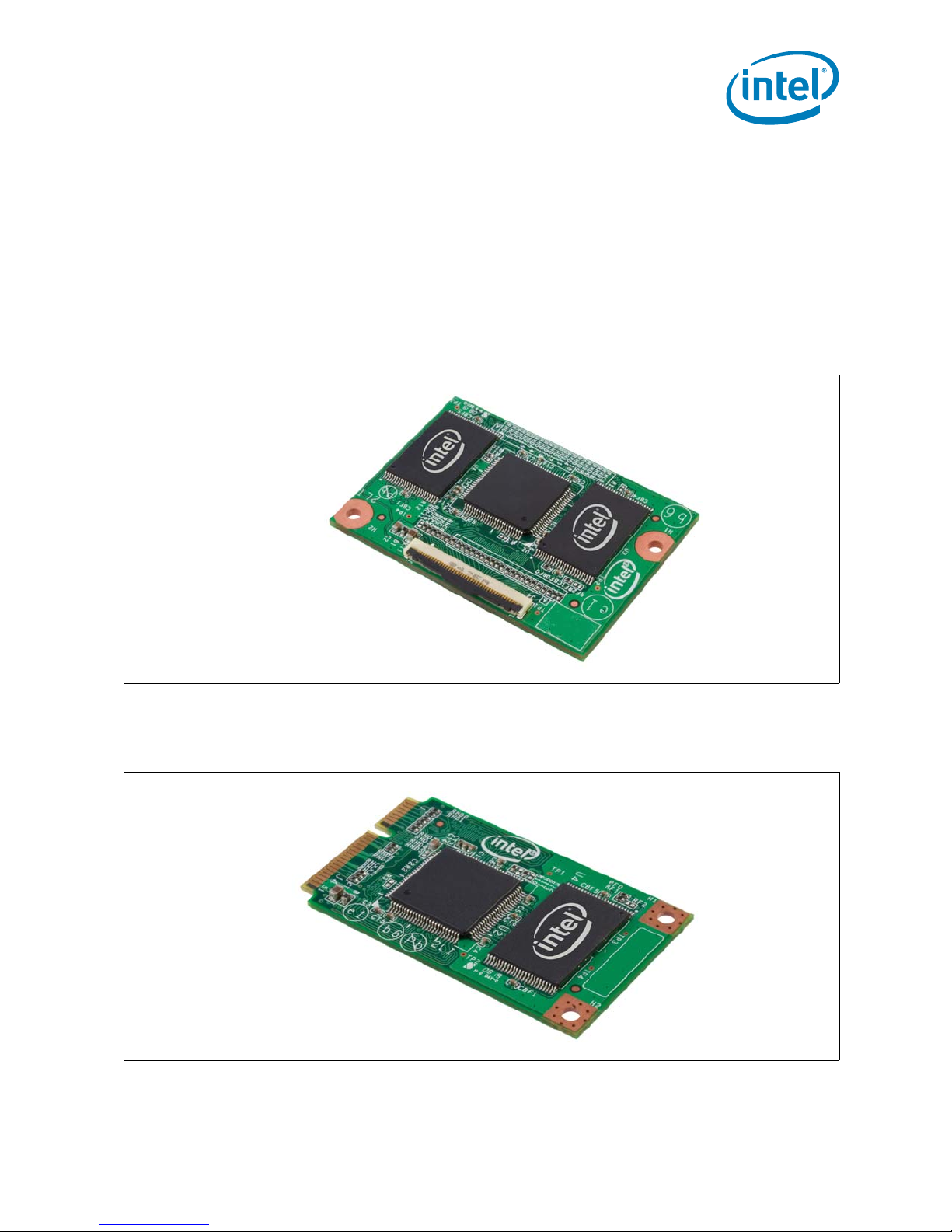
The Intel® Z-P230 PA TA Solid-State Drive (SSD) devices are available in either a 4 GB,
8 GB or 16 GB capacities featuring either a Zero Insertion Force (ZIF) connector or Mini
PCIe form factor for notebooks. The targeted application is for notebook computers
which require a small capacity and durable, low-power storage.
The Intel Z-P230 PATA SSD is electronically-drop-in compatible with mechanical PATA
Hard Disk Drives, but delivers faster boot—the loading and execution of applications
with no moving parts—leading to faster system responsiveness and longer battery life.
Figure 1. Front View of the Intel Z-P230 PATA SSD with ZIF Connector
Figure 2. Front View of the Intel Z-P230 PATA SSD with Mini PCIe Connector
September 2008 Product Manual
Order Number: 319955-003US 5
Intel® Z-P230 PATA Solid State Drive
Page 6

1.1 Key Features
• 4 GB, 8 GB and 16 GB capacity
•ATA UDMA4 support
• ZIF connector or Mini PCIe form factor
•Weight
— ZIF connector: approximately 11 grams
— Mini PCIe form factor: approximately 8 grams
• Less than 1mW idle power (TYP)
•445 mW active power (TYP)
• Uses Intel MLC NAND Flash Memory
• Sequential read: 38 MB/s
• Sequential write: 10 MB/s
• Footprint
— ZIF connector: 38 mm (L) x 54 mm (W) x 3.2 mm (H)
— Mini PCIe form factor: 50.95 mm (L) x 30 mm (W) x 3.8 mm (H)
Intel® Z-P230 PATA SSD
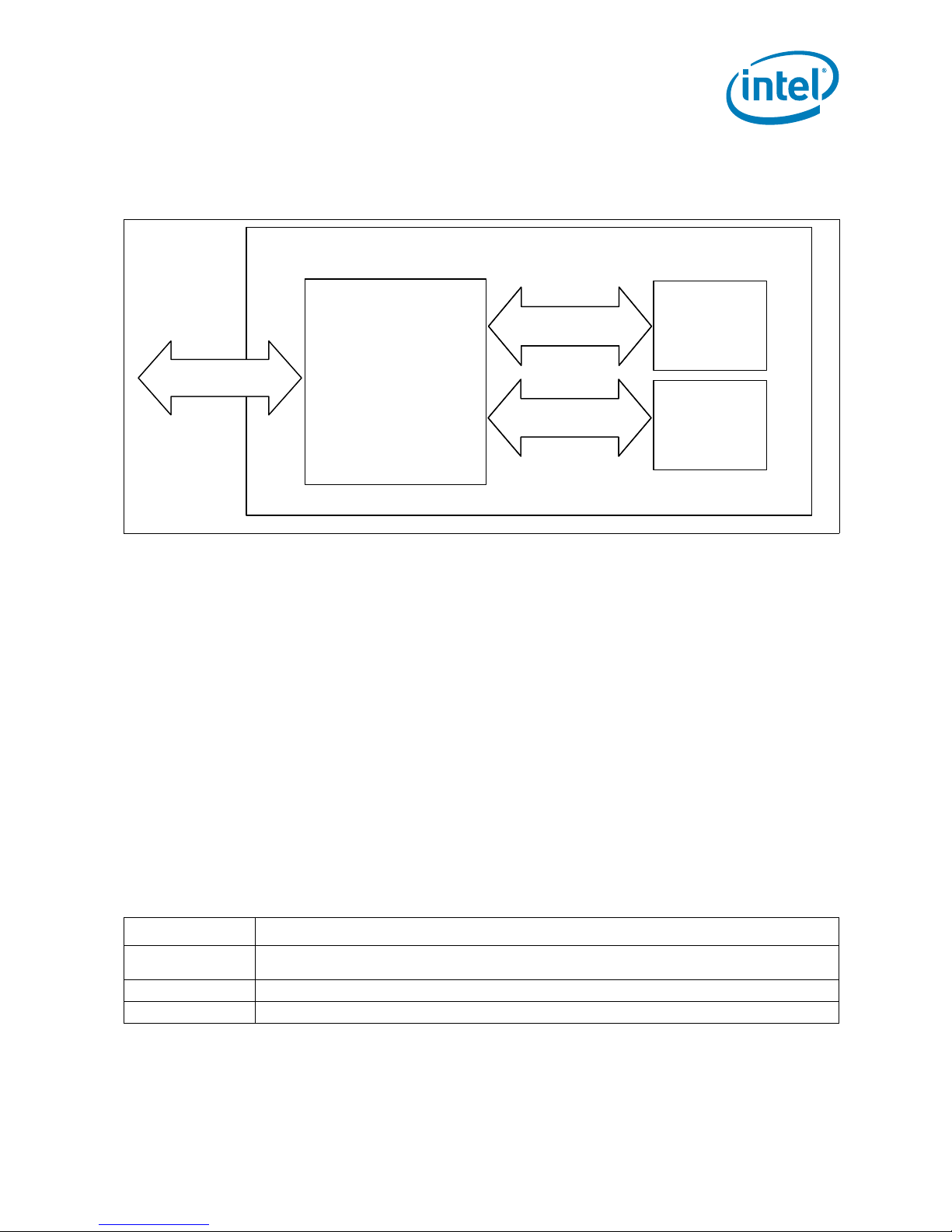
1.2 Architecture
The Intel Z-P230 PATA Solid State Drive is a dual-channel PAT A controller driven SSD
available in a ZIF connector or mini PCIe form factor.
The PA TA controller in the Intel® Z-P230 PAT A Solid State Drive uses a microcontrollerbased architecture that enables two flash memory channels to service read and write
operations. See Figure 3, “Functional Block Diagram of Intel Z-P230 PATA Solid State
Drive” on page 7. Capable of performing flash management functions, the SSD also
implements internal wear leveling to minimize system overhead.
Intel Z-P230 PATA Solid State Drives use Intel MD516 NAND Flash Memory multi-level
cell (MLC) thin-small outline package (TSOP) devices in three capacities: 4 GB, 8 GB
and 16 GB. Refer to the Intel MD516 NAND Flash Memory Datasheet for details about
this component. Please see Section 8.0, “Additional Product Information” on page 22
for more information.
Intel MLC NAND uses the industry-standard ONFI NAND flash memory command set
that is capable of program page cache mode, page read cache mode, two plane
commands and interleaved die operations.
Intel® Z-P230 PATA Solid State Drive
Product Manual September 2008
6 Order Number: 319955-003US
Page 7
Intel® Z-P230 PATA SSD
PATA Interfac ePATA Interfac e
PATA
Controller
Channel 0
DATA 0 [0-7]
Channel 0
DATA 0 [0-7]
Channel 1
DATA 1 [0-7]
Channel 1
DATA 1 [0-7]
NAND
Flash
Memory
NAND
Flash
Memory
1.3 Block Diagram
Figure 3. Functional Block Diagram of Intel Z-P230 PATA Solid State Drive
2.0 Regulatory Compliance
The Intel Z-P230 PATA SSD is compliant with the restriction of Hazardous Substances
(RoHS) directive. It also conforms with standards of CE Mark for European consumer
electronic compliance.
Since the Intel Z-P230 PATA SSD is intended to be contained solely within a personal
computer or similar enclosure (not attached as an external device), the SSD is tested in
representative end-user systems. While the Intel Z-P230 PATA SSD is EMC compliant
(Specification EN55022), computer manufacturers and system integrators should
confirm EMC compliance and provide CE marking for their products.
As a subassembly, no Federal Communications Commission verification or certification
of the device is required. Intel Corporation has tested this device in enclosures to
ensure that the SSD does comply with the limits for a Class B computing device,
pursuant to Subpart J, Part 15 of the FCC rules.
Table 1. Device Compliance
Compliance Description
CE
PB Free Components and materials are lead free.
RoHS Restriction of Hazardous Substance Directive
Indicates conformity with the essential health and safety requirements set out in European Directives
Low Voltage Directive and EMC Directive.
September 2008 Product Manual
Order Number: 319955-003US 7
Intel® Z-P230 PATA Solid State Drive
Page 8
Intel® Z-P230 PATA SSD
3.0 Product Specifications
3.1 Capacity
Table 2. Capacity and User Addressable Sectors
Unformatted User Addressable Sector in LBA mode
4 GB* 7,880,544
8 GB* 15,761,088
16 GB* 31,522,176
Note: Formatting and other functions will use some of the space, thus the listed capacity will not be available entirely for data
storage.
3.2 Performance
Table 3. Read and Write Performance
Operation Access Type MB/second
READ Sustained Sequential Read Bandwidth 38
WRITE Sustained Sequential Write Bandwidth 10
Notes:
1. Queue depth is set to 1.
2. Device measured using IOmeter*.
3. Sampled, not tested.
3.3 Operating Conditions
3.3.1 Maximum Ratings
Stresses greater than those listed under “Absolute Maximum Ratings” may cause
permanent damage to the device. This is a stress rating only, and functional oper ation
of the device at these or any other conditions above those indicated in the operational
sections of this specification is not guaranteed. Exposure to absolute maximum rating
conditions for extended periods may affect reliability.
Table 4. Absolute Maximum Ratings by Device
Parameter Symbol Min Max Unit
Vcc supply voltage Vcc -0.6 +4.6 V
Non-operating temperature Tstg 0 85 °C
Intel® Z-P230 PATA Solid State Drive
Product Manual September 2008
8 Order Number: 319955-003US
Page 9

Intel® Z-P230 PATA SSD
3.3.2 Recommended Operating Conditions
Table 5. Operating Temperature and Voltages
Parameter Symbol Min Typ Max Unit
Operating temperature T
Vcc supply voltage Vcc 3.0 3.3 3.6 V
Ground supply voltage Vss 0 0 0 V
A 0-70°C
3.4 Electrical Characteristics
Table 6. Power Consumption
Setting Value
Active Current 135 mA (TYP)
Active Idle Current 30 mA (TYP)
Idle Current 235 uA (TYP)
Active Power 445 mW
Idle Power <1 mW
Notes:
1. Using UDMA 4 program mode, calculation based on worst case workload condition.
2. Idle power is measured using active power management.
3. Sampled, not tested.
3.5 Environmental Conditions
3.5.1 Temperature
Table 7. Temperature Specifications
Mode Min Max Unit
Ambient Temperature
3.5.2 Altitude
Since there are no moving parts, this device is not susceptible to a lack of air molecules
and will operate correctly to 50,000 feet above sea level.
Operating 0 70
Non-Operating 0 85
o
C
o
C
September 2008 Product Manual
Order Number: 319955-003US 9
Intel® Z-P230 PATA Solid State Drive
Page 10

Intel® Z-P230 PATA SSD
3.5.3 Shock and Vibration
Table 8. Shock and Vibration Characteristics
Condition Value
Non-operating shock 600 G/2 mS
Non-operating vibration 5-500 Hz; 3.13 G
Operating vibration 5-40 Hz; 1.1 G
Notes:
1. Shock specifications assumes that the SSD is mounted securely with the input vibration applied to the drive mounting
screws. Vibration may be applied in the X, Y or Z axis.
2. Vibration specifications assumes that the SSD is mounted securely with the input vibration applied to the drive mounting
screws. Vibration may be applied in the X, Y or Z axis.
3.5.4 Acoustics
This drive has no moving or noise-emitting parts; therefore, it produces negligible
sound (0dB) in all modes of operation.
3.5.5 Electrostatic Discharge (ESD)
The Intel Z-P230 PA T A SSD can withstand an electrostatic discharge of +/- of 4 KV. ESD
testing is done to demonstrate that the units can withstand discharge encountered in
normal handling or operations of the equipment.
3.6 Reliability
Table 9. Reliability Specifications
Parameter Value
Mean Time Between Failure (MTBF) 1,000,000 hours
1,2
15
bits read, max
Non-recoverable read errors 1 sector per 10
Useful Life 3 years
Notes:
1. Based on 60% random workload of 1GB/day on 4GB sku, 2GB/day on 8GB sku and 4GB/day on 16GB sku.
2. 60% of MB data written is random.
Intel® Z-P230 PATA Solid State Drive
Product Manual September 2008
10 Order Number: 319955-003US
Page 11

Intel® Z-P230 PATA SSD
38±0.15
54
±
0.15
1.6±0.1
1.6
1.2
2.5
±
0.05
34.9
±
0.1
4.62±0.1
27±0.05
3.5±0.05
51
±
0.05
Ø
(X2)2.5±0.1
Ø
(X2)7±0.1
Ø
(X2)7±0.1
CONTROLLER
NAND
NAND
ZIF CONN
POS.NO.1
<A2> WAS POS.NO.40
NAND
NAND
4.0 Mechanical Information
Figure 4. Intel Z-P230 PATA SSD with ZIF Connector (Top, Side and Bottom Views)
Notes:
1. All dimensions are in millimeters.
2. Card thickness to be 1.6 ± 0.1 mm, including solder plating unless otherwise specified.
3. Solder plating thickness to be 0.05 mm MAX TYP.
4. Coordinates indicate the center of this connector, or the center of the positioning pin/hole, or the location of #pin
5. Suggested ZIF cable length is 3 inches.
September 2008 Product Manual
Order Number: 319955-003US 11
Intel® Z-P230 PATA Solid State Drive
Page 12

Figure 5. ZIF Connector Dimensions (Top, Side and Profile Views)
Intel® Z-P230 PATA SSD
Note: All dimensions are in millimeters.
Intel® Z-P230 PATA Solid State Drive
Product Manual September 2008
12 Order Number: 319955-003US
Page 13

Intel® Z-P230 PATA SSD
30
0
-0.3
24.2
±
0.1
Ø
(X2)2.6±0.1
3.2
48.05±0.1
50.95
0
-0.3
3.85
±
0.1
1.5
3.25
R (X2)0.8
1
±
0.1
1.6
1.2
MIN5.1
MIN5.1
CONTROLLERNAND
COMPONENT KEEP OUT
AREA FOR CONNECTOR
NAND
COMPONENT KEEP OUT
AREA FOR CONNECTOR
25.7
Figure 6. Intel Z-P230 PATA SSD with Mini PCIe Connector (Top, Side and Bottom
Views)
Notes:
1. All dimensions are in millimeters.
2. Card thickness to be 1.0 ± 0.1 mm, including solder plating unless otherwise specified.
3. Solder plating thickness to be 0.05 mm MAX TYP.
4. Coordinates indicate the center of this connector, or the center of the positioning pin/hole, or the location of #pin.
September 2008 Product Manual
Order Number: 319955-003US 13
Intel® Z-P230 PATA Solid State Drive
Page 14

Intel® Z-P230 PATA SSD
5.0 Pin Assignments and Signal Descriptions
5.1 Pin Assignments
Table 10. Intel Z-P230 with ZIF Connector - 40 Pin Assignments
Pin
Number
1Reserved 11 DQ4 21 GND 31 DA1
2Reserved 12 DQ11 22DMARQ 32PDIAG#
3 RESET# 13 DQ3 23 GND 33 DA0
4 GND 14 DQ12 24 DIOW# 34 DA2
5 DQ7 15 DQ2 25 DIOR# 35 CS0#
6 DQ8 16 DQ13 26 GND 36 CS1#
7 DQ6 17 DQ1 27 IORDY 37 DASP#
8 DQ9 18 DQ14 28 GND 38 VCC
9DQ5 19DQ0 29DMACK# 39VCC
10 DQ10 20 DQ15 30 INTRQ 40 Reserved
Signal
Pin
Number
Signal
Pin
Number
Signal
Pin
Number
Signal
Table 11. Intel Z-P230 with Mini PCIe Form Factor - 52 Pin Assignments
Pin Number Signal Signal Pin Number
1DQ0 DQ152
3DQ1 GND4
5DQ2 DQ146
7DQ3 DQ138
9 GND DQ12 10
11 DQ4 DQ11 12
13 DQ5 DQ10 14
15 GND DQ9 16
17 DQ6 GND 18
19 DQ7 DQ8 20
21 GND RESET# 22
23 NC DIOW 24
25 NC NC 26
27 GND DIOR 28
29 GND DMACK# 30
31 NC DMARQ 32
33 NC GND 34
35 GND NC 36
37 DA0 NC 38
39 DA1 GND 40
Intel® Z-P230 PATA Solid State Drive
Product Manual September 2008
14 Order Number: 319955-003US
Mechanical Key
Page 15

Intel® Z-P230 PATA SSD
Table 11. Intel Z-P230 with Mini PCIe Form Factor - 52 Pin Assignments
Pin Number Signal Signal Pin Number
41 DA2 IORDY 42
43 NC INTRRQ 44
45 NC CS0# 46
47 VCC CS1# 48
49 VCC GND 50
51 VCC NC 52
Note: The Mini PCIe form factor does not use the DASP# or PDAIG signals.
5.2 Signal Descriptions
Table 12. Signal Symbols and Descriptions
Symbol Type Description
CS0#, CS1# Input
DA[0...2] Input
DASP# Input/Output
DIOR# Input
DIOW# Input
DMACK# Input
DMARQ Output
DNU Do Not Use. Must be left unconnected.
DQ[0...15] Input/Output 16-bit bidirectional I/O interface.
GND Supply Ground connection.
INTRQ Output Device uses the Interrupt Request signal to interrupt the host.
IORDY Output
NC Not connected.
PDIAG# Input/Output
Reserved Reserved for Future Use.
RESET# Input The host asserts this signal to reset the device.
VCC Supply Power supply.
The host uses CS0# to select task file registers and CS1# to select alternate
status registers and other device control register.
Device address signals used by the host to access device registers or data
port.
The Device Active/Slave Present signal.
Note: the Mini PCIe form factor does not use this signal.
The I/O Read Enable signal is the strobe signal asserted by the host to read
device registers or the data port.
The I/O Write Enable signal is the strobe signal asserted by the host to write
device registers or the data port.
The host uses the DMA Acknowledge si gnal to acknowledge the receipt of the
DMA Request and that it is ready to initiate DMA transfers.
The DMA Request signal is asserted by the drive when it is ready for data
transfer between it and the host. IORD and IOWR signals are used to control
the direction of data transfer.
The device asserts the I/O Ready signal to tell the host to extend the host
transfer cycle.
The Pass Diagnostic signal is used by the master/sla ve handsh ake p rotocol to
determine if the device has passed diagnostics.
Note: the Mini PCIe form factor does not use this signal.
September 2008 Product Manual
Order Number: 319955-003US 15
Intel® Z-P230 PATA Solid State Drive
Page 16

Intel® Z-P230 PATA SSD
6.0 Command Sets
The Intel® Z-P230 PATA SSD device supports all the mandatory ATA commands as
defined in the ATA/ATAPI-5 specification.
6.1 ATA General Feature Command Set
The Intel® Z-P230 PATA SSD device supports the ATA General Feature command set
(non-PACKET).
Table 13. ATA General Feature Commands
Command Name Code
EXECUTE DEVICE DIAGNOSTIC 90h
IDENTIFY DEVICE ECh
IDENTIFY DEVICE DMA EEh
INITIALIZE DRIVE PARAMETERS 91h
NOP 00h
READ BUFFER E4h
READ DMA C8h, C9h
READ LONG 22h, 23h
READ MULTIPLE C4h
READ NATIVE MAX ADDRESS F8h
READ SECTOR(S) 20h, 21h
READ VERIFY SECTOR(S) 40h, 41h
RECALIBRATE 1Xh
SEEK 7Xh
SET FEATURES EFh
SET MULTIPLE MODE C6h
SMART B0h
TRANSLATE SECTOR 87h
WRITE BUFFER E8h
WRITE DMA CAh, CBh
WRITE LONG 32h, 33h
WRITE MULTIPLE C5h
WRITE MULTIPLE without ERASE CDh
WRITE SECTOR(S) 30h, 31h
WRITE SECTOR(S) without ERASE 38h
WRITE VERIFY 3Ch
Intel® Z-P230 PATA Solid State Drive
Product Manual September 2008
16 Order Number: 319955-003US
Page 17

Intel® Z-P230 PATA SSD
6.1.1 IDENTIFY DEVICE DATA
The following table details the data returned after issuing an IDENTIFY DEVICE (ECh)
command.
Table 14. Returned Sector Data
Word Default Value Bytes Description
0 044Ah 2 General configuration bit-significant information
4 GB: 1E8Ah
1
2 0000h 2 Reserved
3 0010h 2 Default number of Logical heads
4 7E00h 2 Retired
5 0200h 2 Retired
6 003Fh 2 Default number of logical sectors per logical track
7-8 XXXX 4 Reserved for assignment by the CompactFlash* Association
9 0000h 2 Reserved
10-19 XXXX 20 Serial number (20 ASCII characters)
20 0002h 2 Retired/obsolete
21 0002h 2 Retired/ Obsolete
22 0004h 2 Retired/ Obsolete
23-26 XXXX 8 Firmware revision (8 ASCII characters)
8 GB: 3D14h
16 GB: 3FFFh
2 Default number of Logical cylinders
September 2008 Product Manual
Order Number: 319955-003US 17
Intel® Z-P230 PATA Solid State Drive
Page 18

Table 14. Returned Sector Data (Continued)
Word Default Value Bytes Description
4 GB: 5353h, 4450h
414Dh, 4D30h
3030h, 3447h
3120h, 2020h
2020h, 2020h
2020h, 2020h
27-46
2020h, 2020h
2020h, 2020h
2020h, 2020h
2020h, 2020h
8 GB: 5353h, 4450h
414Dh, 4D30h
3030h, 3847h
3120h, 2020h
2020h, 2020h
2020h, 2020h
2020h, 2020h
2020h, 2020h
2020h, 2020h
2020h, 2020h
16 GB: 5353h, 4450h
414Dh, 4D30h
3031h, 3647h
3145h, 5320h
2020h, 2020h
2020h, 2020h
2020h, 2020h
2020h, 2020h
2020h, 2020h
2020h, 2020h
40
Model number (40 ASCII characters)
Default Value column shows the hex values for ZIF connector based sku:
4 GB: SSDPAMM0004G1
8 GB: SSDPAMM0008G1
16 GB: SSDPAMM0016G1
Other hex values include:
Production SSD with Mini PCIe connector:
4 GB: SSDPAEM0004G1
5353h, 4450h, 4145h, 4D30h, 3030h, 3447h, 3120h, 2020h, 2020h,
2020h, 2020h, 2020h, 2020h, 2020h, 2020h, 2020h, 2020h, 2020h,
2020h, 2020h
8 GB: SSDPAEM0008G1
5353h, 4450h, 4145h, 4D30h, 3030h, 3847h, 3145h, 5320h, 2020h,
2020h, 2020h, 2020h, 2020h, 2020h, 2020h, 2020h, 2020h, 2020h,
2020h, 2020h
16 GB: SSDPAEM0016G1
5353h, 4450h, 4145h, 4D30h, 3031h, 3647h, 3145h, 5320h, 2020h,
2020h, 2020h, 2020h, 2020h, 2020h, 2020h, 2020h, 2020h, 2020h,
2020h, 2020h
Intel® Z-P230 PATA SSD
Maximum number of sectors transferred per interrupt on Read/Write
47 8001h 1
48 0000h 2 Reserved
49 2B00 2 Capabilities: DMA, LBA, IORDY, and standby timer functions supported
50 4000h 2 Capabilities
51 0200h 2 Obsolete
52 0000h 2 Obsolete
53 0007h 2 Data fields 54 to 58, 64 to 70 and 88 are valid
4 GB: 1E8Ah
54
55 0010h 2 Number of current logical heads. Obsolete.
56 003Fh 2 Number of current logical sectors per logical track. Obsolete.
57-58
59 0101h 2 Multiple sector setting is valid
Intel® Z-P230 PATA Solid State Drive
Product Manual September 2008
18 Order Number: 319955-003US
8 GB: 3D14h
16 GB: 3FFFh
4 GB: 3F60h, 0078h
8 GB: 7EC0h, 00F0h
16 GB: 00FBh, FC10h
Multiple command
1 = for a single-channel card
2 = two-channel card
2 Number of current logical cylinders. Obsolete.
4 Current capacity in sectors. Obsolete
Page 19

Intel® Z-P230 PATA SSD
Table 14. Returned Sector Data (Continued)
Word Default Value Bytes Description
4 GB: 3F60h, 0078h
60-61
62 0000h 2 Obsolete
63 0007h 2 Multi-word DMA transfer mode - 2, 1, 0
64 0003h 2 Advanced PIO Modes - 4, 3, 2, 1, 0
65 0078h 2 Minimum multi word DMA cycle time per word
66 0078h 2 Recommended multi word DMA cycle time
67 0078h 2 Minimum PIO cycle time without flow control
68 0078h 2 Minimum PIO cycle time IORDY with flow control
69-79 0000h 22 Reserved
80 0030h 2 Major version number, ATA-4 and ATA-5 support
81 0000h 2 Minor version number, not reported
82 700Bh 2
83 5004h 2 Command set: FLUSH CACHE, CFA feature set
84 4000h 2 Command set/feature supported extension
85 7009h 2
86 1004h 2 Command set enabled: FLUSH CACHE, CFA feature set
87 4000h 2 Command set/feature default.
88 203Fh 2 UDMA mode 4 and below are supported.
89 001Eh 2 Time required for security erase unit completion
90 001Eh 2 Time required for enhanced security erase unit completion
91 0000h 2 Current advanced power management value
92 FFFEh 2 Master Password Revision Code
93 0000h 2 Hardware reset result
94-127 0000h 68 Reserved
128 0029h 2 Security status
129 0003h 2 Vendor specific
130-159 0000h 60 Reserved
160 1000h 2 CFA Power mode 1 (Disabled)
161-255 0000h 190 Reserved
8 GB: 7EC0h, 00F0h
16 GB: 01E0h, FD80h
4 Total number of sectors addressable in LBA mode
Command set: READ BUFFER, WRITE BUFFER, power management feature
set, NOP, SMART, Removable Media feature set
Command set enabled: READ BUFFER, WRITE BUFFER, NOP, power
management feature set, SMART feature set
September 2008 Product Manual
Order Number: 319955-003US 19
Intel® Z-P230 PATA Solid State Drive
Page 20

Intel® Z-P230 PATA SSD
6.1.2 READ MULTIPLE and WRITE MULTIPLE Command Value
Set the following value when executing READ MULTIPLE (C4h) and WRITE MULTIPLE
(C5h) commands.
Table 15. Set Multiple Commands Parameter
Feature Sector Count Register Value
Set sectors per block to use on all subsequent READ MULTIPLE (C4h) and WRITE
MULTIPLE (C5h) commands.
01h
6.1.3 SET FEATURES Subcommands
The following table identifies the subcommands for the SET FEATURES (EFh) command.
Table 16. Subcommands for the SET FEATURES Command
Subcommand Name Feature Register Value
Enable 8-bit data transfer 01h
Set transfer mode based on value in 03h
Disable Read Look Ahead 55h
Disable Power on Reset (POR) establishment 66h
NOP - Accepted 69h
Disable 8-bit data transfer 81h
NOP - Accepted 96h
Accepted for backward compatibility 97h
Set host current source capability 9Ah
4 bytes of data applied on READ/WRITE BBh
Enable Power on Reset (POR) establishment CCh
6.1.4 SMART Subcommand Set
The SMART RETURN STATUS (DAh) command returns a pass/fail value based on the
current status of the Z-P230 PA TA SSD. The BIOS or system software that interfaces to
SMART should issue this command at boot up and upon resume from a standby or
hibernate c o ndition. If the status returned is PASS, the boot up or resume sequence
should continue as normal. If however the status returned is FAIL, the BIOS or system
software should issue a warning to the end us er that their SSD is approaching it’ s drive
wear-out condition and recommend that the end user back up their SSD.
The following table details the register value for each of the subcommands available
when using the SMART (B0h) command:
Table 17. SMART Subcommands
Subcommand Name Feature Register Value
SMART READ ATTRIBUTE D0h
SMART READ ATTRIBUTE THRESHOLDS D1h
SMART ENABLE ATTRIBUTE AUTOSAVE D2h*
Intel® Z-P230 PATA Solid State Drive
Product Manual September 2008
20 Order Number: 319955-003US
Page 21

Intel® Z-P230 PATA SSD
Table 17. SMART Subcommands (Continued)
Subcommand Name Feature Register Value
SMART DISABLE ATTRIBUTE AUTOSAVE D2h*
SMART ENABLE OPERATION D8h
SMART DISABLE OPERATIONS D9h
SMART RETURN STATUS DAh
Note: The Sector Count Register v alue de termines whethe r to implement SMAR T ENABLE ATTRIBUTE AUTOSAVE (F1h) or SMAR T
DISABLE ATTRIBUTE AUTOSAVE (00h).
6.2 Power Management Command Set
The Intel® Z-P230 PATA SSD devices support the Power Management command set.
Table 18. Power Management Commands
Command Name Code
CHECK POWER MODE E5h, 98h
IDLE E3h, 97h
IDLE IMMEDIATE E1h, 95h
SLEEP E6h, 99h
STANDBY E2h, 96h
STANDBY IMMEDIATE E0h, 94h
7.0 References
This document also references standards and specifications defined by a variety of
organizations. Please use the following information to identify the location of an
organization’s standards information.
Table 19. Standards References
Date or
Revision Number
February 2000 ATA-5
January 2007
December 2004
December 2006 Open NAND Flash Interface (ONFI) Specification 1.0 http://www.onfi.org/docs/ONFI_1_0_Gold.pdf
September 2008 Product Manual
Order Number: 319955-003US 21
JEDEC Standard: Electrostatic Discharge (ESD)
Sensitivity Testing Human Body Model (HBM)
JEDEC Standard JESD22-C101C: Field-Induced
Charged-Device Model Test Method for ElectrostaticDischarge-Withstand Thresholds of Microelectronic
Components
Title Location
http://www.t13.org/Documents/
UploadedDocuments/project/d1321r3-ATAATAPI-5.pdf
http://www.jedec.org/download/search/
default2.cfm
http://www.jedec.org/download/search/
default2.cfm
Intel® Z-P230 PATA Solid State Drive
Page 22

Intel® Z-P230 PATA SSD
8.0 Additional Product Information
For detailed information about a product mentioned in this document, please refer to
the corresponding datasheet or application note.
Table 20. Addition Product Information
Order Number Title Type*
316339-003US Intel® MD516 NAND Flash Memory Datasheet Production
Note: Customers who request access to Advanced datasheets must have a a non-disclosure agreement (NDA) with Intel. We
release Advanced datasheets prior to Preliminary datasheets, which are released around the time a product is sampled.
Production datasheets become available when the part is mass produced. To obtain a copy of these documents, please
contact your Intel field sales representative.
9.0 Glossary
This document incorporates many industry- and device-specific words. Use the
following list to define a variety of terms and acronyms.
Table 21. Glossary of Terms and Acronyms
Term Definition
ATA Advanced Technology Attachment
CE
CFA CompactFlash Association
CPRM Content Protection for Recordable Media
CRC Cyclic Redundancy Check
DDP Dual Die Package
DMA Direct Memory Access
ECC Error Correction Code
EMC ElectroMagnetic Compatibility
ESD Electrostatic Discharge
FCC Federal Communications Commission
GB
HDD Hard Disk Drive
IDE Integrated Device Electronics
LBA Logical Block Addressing
MB
Mini PCIe Mini Peripheral Component Interconnect Express (PCIe)
MLC Multi-Level Cell
MTBF Mean Time Between Failure
MWDMA Multi-Word DMA
NOP No Operation
ODM Original Design Manufacturer
The CE conformity marking applies to products regulated by certain European health,
safety and environmental protection legislation.
Giga-byte. Defined as 1x10
formatting and other functions, and therefore, is not available for data storage.
Mega-byte. Defined as 1x10
formatting and other functions, and therefore, is not available for data storage.
9
bytes. Please note that some of the listed cap acity is used for
6
bytes. Please note that some of the listed capacity is used for
Intel® Z-P230 PATA Solid State Drive
Product Manual September 2008
22 Order Number: 319955-003US
Page 23

Intel® Z-P230 PATA SSD
Table 21. Glossary of Terms and Acronyms (Continued)
Term Definition
OEM Original Equipment Manufacturer
ONFI Open NAND Flash Interface
PATA Parallel ATA
PIO Programmable Input / Output
QDP Quad Die Package
SDP Single Die Package
SSD Solid state drive
UDMA Ultra DMA, also know Ultra ATA
ZIF Zero Insertion Force
10.0 Revision History
Date Revision Description
“Intel Z-P230 PATA SSD Ordering Information” on
“Intel Z-P230 PATA SSD Ordering Information” on
.
September
2008
July 2008 002
June 2008 001
003
Updated the Decoder and
page 2
Updated
Added footnote to Table 9, “Reliability Specifications” on page 10
Updated mechanical drawing of ZIF module Figure 4, “Intel Z-P230 PATA SSD with ZIF
Connector (Top, Side and Bottom Views)” on page 11
Modified values and content in the following tables:
Updated values and added Mini PCIe data on the front page.
Updated the Decoder and
page 2
Modified
page 6
Added the following sections:
Modified Figure 3, “Functional Block Diagram of Intel Z-P230 PATA Solid State
Drive” on page 7
Added the following tables:
.
Section 6.1.4, “SMART Subcommand Set” on page 20
Table 6, “Power Consumption” on page 9
•
• Table 14, “Returned Sector Data” on page 17
.
Section 1.0, “Overview” on page 5 and Section 1.1, “Key Features” on
.
Section 1.2, “Architecture” on page 6
•
• Section 8.0, “Additional Product Information” on page 22
Table 7, “Temperature Specifications” on page 9
•
• T able 11, “Intel Z-P230 with Mini PCIe Form Factor - 52 Pin Assignments”
on page 14
Added the following figures:
Figure 2, “Front View of the Intel Z-P230 PATA SSD with Mini PCIe
•
Connector” on page 5
• Figure 6, “Intel Z-P230 PATA SSD with Mini PCIe Connector (Top, Side
and Bottom Views)” on page 13
Modified values and content in the following tables:
Table 2, “Capacity and User Addressable S ectors” on page 8
•
• Table 3, “Read and Write Performance” on page 8
• Table 13, “ATA General Feature Commands” on page 16
• Table 14, “Returned Sector Data” on page 17
• Table 21, “Glossary of Terms and Acronyms” on page 22
Initial Release. Earlier information released as Castle Point P A TA Modular Solid State Drive Advance
Datasheet - 319546-002US.
September 2008 Product Manual
Order Number: 319955-003US 23
Intel® Z-P230 PATA Solid State Drive
Page 24

Intel® Z-P230 PATA SSD
Intel® Z-P230 PATA Solid State Drive
Product Manual September 2008
24 Order Number: 319955-003US
 Loading...