

Page 1

Intel® Entry Storage System SS4200-E
User Guide
A Guide for Technically Qualified Assemblers of Intel® Identified Subassemblies/
Products
Intel Order Number E20699-002
Page 2

Disclaimer
Information in this document is provided in connection with Intel® products. No license, express or implied, by
estoppel or otherwise, to any intellectual property rights is granted by this document. Except as provided in Intel's
Terms and Conditions of Sale for such products, Intel assumes no liability whatsoever, and Intel disclaims any
express or implied warranty, relating to sale and/or use of Intel® products including liability or warranties relating to
fitness for a particular purpose, merchantability, or infringement of any patent, copyright or other intellectual property
right. Intel products are not designed, intended or authorized for use in any medical, life saving, or life sustaining
applications or for any other application in which the failure of the Intel product could create a situation where
personal injury or death may occur. Intel may make changes to specifications and product descriptions at any time,
without notice.
Intel® server boards contain a number of high-density VLSI and power delivery components that need adequate
airflow for cooling. Intel's own chassis are designed and tested to meet the intended thermal requirements of these
components when the fully integrated system is used together. It is the responsibility of the system integrator that
chooses not to use Intel developed server building blocks to consult vendor datasheets and operating parameters to
determine the amount of airflow required for their specific application and environmental conditions. Intel
Corporation can not be held responsible if components fail or the server board does not operate correctly when used
outside any of their published operating or non-operating limits.
Intel, Intel Pentium, and Intel Xeon are trademarks or registered trademarks of Intel Corporation or its subsidiaries in
the United States and other countries.
* Other names and brands may be claimed as the property of others.
Copyright © 2007, Intel Corporation. All Rights Reserved
ii Intel® Entry Storage System SS4200-E User Guide
Page 3
Safety Information
Important Safety Instructions
Read all caution and safety statements in this document before performing any of the
instructions. See also Intel Server Boards and Server Chassis Safety Information on the
®
Server Deployment Toolkit CD and/or at http://support.intel.com/support/
Intel
motherboards/server/sb/cs-010770.htm.
Wichtige Sicherheitshinweise
Lesen Sie zunächst sämtliche Warnund Sicherheitshinweise in diesem Dokument, bevor
Sie eine der Anweisungen ausführen. Beachten Sie hierzu auch die Sicherheitshinweise zu
Intel-Serverplatinen und Servergehäusen auf der Intel
oder unter http://support.intel.com/support/motherboards/server/sb/cs-010770.htm.
Safety Information
®
Server Deployment Toolkit CD
Consignes de sécurité
Lisez attention toutes les consignes de sécurité et les mises en garde indiquées dans ce
document avant de suivre toute instruction. Consultez Intel Server Boards and Server
Chassis Safety Information sur le Intel
vous sur le site http://support.intel.com/support/motherboards/server/sb/cs-010770.htm.
®
Server Deployment Toolkit CD ou bien rendez-
Instrucciones de seguridad importantes
Lea todas las declaraciones de seguridad y precaución de este documento antes de realizar
重要安全指导
cualquiera de las instrucciones. Vea Intel Server Boards and Server Chassis Safety
Information en el Intel
support/motherboards/server/sb/cs-010770.htm.
®
Server Deployment Toolkit CD y/o en http://support.intel.com/
Intel® Entry Storage System SS4200-E User Guide iii
Page 4

Safety Information
Warnings
These warnings and cautions apply whenever you remove the enclosure cover to access
components inside the storage system. Only a technically qualified person should
maintain or configure the storage system.
Heed safety instructions: Before working with your storage product, whether you are
using this guide or any other resource as a reference, pay close attention to the safety
instructions. You must adhere to the assembly instructions in this guide to ensure and
maintain compliance with existing product certifications and approvals. Use only the
described, regulated components specified in this guide. Use of other products /
components will void the UL listing and other regulatory approvals of the product and
will most likely result in noncompliance with product regulations in the region(s) in which
the product is sold.
System power on/off: The power button DOES NOT turn off the system AC power. To
remove power from storage system, you must unplug the AC power cord from the wall
outlet or the chassis. Make sure the AC power cord is unplugged before you open the
chassis, add, or remove any components.
Hazardous conditions, devices and cables: Hazardous electrical conditions may be
present on power, telepho ne, and co mmuni catio n cables. Turn off the storage system and
disconnect the power cord, telecommunications systems, networks, and modems attached
to the storage system before opening it. Otherwise, personal injury or equipment damage
can result.
Electrostatic discharge (ESD) and ESD protection: ESD can damage disk drives,
boards, and other parts. We recommend that you perform all procedures in this document
only at an ESD workstation. If one is not available, provide some ESD protection by
wearing an anti-static wrist strap attached to chassis ground (any unpainted metal surface)
on your storage system when handling parts.
ESD and handling boards: Always handle boards carefully. They can be extremely
sensitive to ESD. Hold boards only by their edges. Do not touch the connector contacts.
After removing a board from its protective wrapper or from the storage server, place the
board component side up on a grounded, static-free surface. Use a conductive foam pad if
available but not the board wrapper. Do not slide board over any surface.
Installing or removing jumpers: A jumper is a small plastic encased conductor that slips
over two jumper pins. Some jumpers have a small tab on top that you can grip with your
fingertips or with a pair of fine needle nosed pliers. If your jumpers do not have such a
tab, take care when using needle nosed pliers to remove or install a jumper; grip the
narrow sides of the jumper with the pliers, never the wide sides. Gripping the wide sides
can damage the contacts inside the jumper, causing intermittent problems with the
function controlled by that jumper. Take care to grip with, but not squeeze, the pliers or
other tool you use to remove a jumper, or you may bend or break the pins on the board.
Reinstalling enclosure cover: For proper cooling and airflow, always install the
enclosure cover before turning on the storage system. Operating it without the enclosure
cover in place can damage system parts.
iv Intel® Entry Storage System SS4200-E User Guide
Page 5

Preface
About this Manual
Thank you for purchasing and using the Intel® Entry Storage System SS4200-E.
This manual is written for system technicians who are responsible for configuring,
troubleshooting, upgrading, and repairing this storage system. This document provides a
brief overview of the features of the product, a list of accessories or other components you
may need, troubleshooting information, and instructions on how to add and replace
components on the Intel
manual, see http://support.intel.com/support/motherboards/server/ss4200-e/.
Product Contents, Order Options, and Accessories
®
Entry Storage System SS4200-E. For the latest version of this
Preface
Your storage system ships with the following items:
• Intel
®
Entry Storage System SS4200-E
• Attention document, in the product box
• Intel
®
Entry Storage System SS4200-E Quick Start User's Guide, in the product box
• AC power cord (North America only)
• RVR (rotational vibration reduction) hard drive screws
• Resource CD
In addition, you may need or want to purchase the following accessory item for your
storage system:
• Hard drives
For information about which accessories, memory, and third-party hardware have been
tested and can be used with your storage system, and for ordering information for Intel
products, see http://support.intel.com/support/motherboards/server/ss4200-e/compat.htm.
Additional Information and Software
If you need more information about this product or information about the accessories that
can be used with this storage system, use the following resources. These files are
available at http://support.intel.com/support/motherboards/server/ss4200-e/
®
Intel® Entry Storage System SS4200-E User Guide v
Page 6

Preface
Unless otherwise indicated in the following table, once on this Web page, type the
document or software name in the search field at the left side of the screen and select the
option to search “This Product.”
For this information or
software
For in-depth technical
information about this
product
If you just received this
product and need to install
it
Accessories or other Intel
server products
Hardware (peripherals,
hard disk drives) and
operating systems that
have been validated by
Intel for this product
For software to manage
your Intel® storage system
Use this Document or Software
®
Intel
Entry Storage System SS4200-E Technical Product
Specification
http://support.intel.com/support/motherboards/server/ss4200-e/
®
Intel
Entry Storage System SS4200-E Quick Start User's Guide in
the product box
Spares and Configuration Guide
Tested Hardware and Operating Systems List
http://support.intel.com/support/motherboards/server/ss4200-e/
Third-party software list
vi Intel® Entry Storage System SS4200-E User Guide
Page 7

Contents
Contents
Safety Information ..................................................................................................... iii
Important Safety Instructions ................................................................................................ iii
Wichtige Sicherheitshinweise ............................................................................................... iii
Consignes de sécurité .......................................................................................................... iii
Instrucciones de seguridad importantes ............................................................................... iii
Warnings............................................................................................................................... iv
Preface .........................................................................................................................v
About this Manual .................................................................................................................. v
Product Contents, Order Options, and Accessories ..............................................................v
Additional Information and Software ......................................................................................v
Storage System Features .......................................................................................... 1
Enclosure Core Product .........................................................................................................1
Chassis ..................................................................................................................................3
System Board Subsystem .....................................................................................................3
System Board I/O Panel ............................................................................................................. 4
System Board Layout ............................................................................................................ 5
Front Panel ............................................................................................................................ 6
Rear Panel .............................................................................................................................6
Power Supply .........................................................................................................................7
Power Supply Output Loom ........................................................................................................ 7
Cooling Fans ..........................................................................................................................7
Drive Retention Assembly .....................................................................................................7
Disk Drive Status Indicator ......................................................................................................... 7
Spare Parts and Accessories ................................................................................................8
Getting Started ............................................................................................................9
Planning Your Installation ......................................................................................................9
Disk Drive Numbering Convention .........................................................................................9
Enclosure Installation Prerequisites .....................................................................................10
Preparation of Site and Host Server ......................................................................................... 10
Planning and Configuring Your Installation ............................................................................... 10
Power Cord Connection .......................................................................................................10
Grounding Checks .................................................................................................................... 10
Operation ...................................................................................................................11
Before You Begin .................................................................................................................11
Power On .............................................................................................................................11
Starting the Drives ...............................................................................................................11
Disk Drive Status LEDs ............................................................................................................ 11
Intel® Entry Storage System SS4200-E User Guide vii
Page 8

Contents
Front Panel LEDs and Switches.......................................................................................... 12
Power Down ........................................................................................................................ 13
Reset/Recovery................................................................................................................... 14
Hardware Installations and Upgrades .....................................................................15
Before You Begin ................................................................................................................ 15
Tools and Supplies Needed ..................................................................................................... 15
System References .................................................................................................................. 15
Installing Feet ...................................................................................................................... 15
Initial Setup ............................................................................................................................... 17
Converting Feet from Horizontal to Vertical Configuration ....................................................... 18
Converting Feet from Vertical to Horizontal Configuration ....................................................... 19
Removing or Installing the Enclosure Cover ....................................................................... 19
Removing the Enclosure Cover ................................................................................................ 20
Installing the Enclosure Cover .................................................................................................. 21
Installing a Hard Drive......................................................................................................... 22
Replacing a Power Supply .................................................................................................. 25
Connecting the Power Cord ................................................................................................ 31
Grounding Checks .................................................................................................................... 31
Replacing a Cooling Fan..................................................................................................... 32
Replacing Memory .............................................................................................................. 41
Replacing the CMOS Battery .............................................................................................. 44
Boot Drive............................................................................................................................ 47
Replacing an IDE DOM (if present) .......................................................................................... 47
Troubleshooting and Problem Solving ...................................................................51
Overview ............................................................................................................................. 51
Initial Start-up Problems ........................................................................................................... 51
LEDs .................................................................................................................................... 51
Front Panel ............................................................................................................................... 52
Troubleshooting ................................................................................................................... 52
Power Supply Faults ................................................................................................................. 52
Thermal Control ........................................................................................................................ 52
Disk Drive Status Faults ...................................................................................................... 53
Dealing with Hardware Faults ............................................................................................. 53
Technical Specifications ..........................................................................................55
Dimensions .......................................................................................................................... 55
Weight ................................................................................................................................. 55
AC Power Module (1 250-W Power Supply) ....................................................................... 55
Power Cord ......................................................................................................................... 56
Cooling Fan ......................................................................................................................... 56
Environment ........................................................................................................................ 56
A Regulatory and Compliance Information ...........................................................59
Product Regulatory Compliance .......................................................................................... 59
viii Intel® Entry Storage System SS4200-E User Guide
Page 9

Contents
Intended Application ................................................................................................................. 59
Product Safety Compliance ......................................................................................................59
Product EMC Compliance - Class B Compliance ..................................................................... 60
Certifications / Registrations / Declarations .............................................................................. 60
Product Regulatory Compliance Markings ............................................................................... 61
Electromagnetic Compatibility Notices ................................................................................62
FCC Statement (USA) .............................................................................................................. 62
ICES-003 (Canada) .................................................................................................................. 63
Europe (CE Declaration of Conformity) .................................................................................... 63
VCCI (Japan) ............................................................................................................................ 63
BSMI (Taiwan) .......................................................................................................................... 63
RRL (Korea) .............................................................................................................................. 64
End of Life / Product Recycling ............................................................................................64
Restriction of Hazardous Substances (RoHS) Compliance .................................................64
B Warranty ............................................................................................................... 65
Limited Warranty for Intel® Chassis Subassembly Products ..............................................65
Extent of Limited Warranty ..................................................................................................65
Warranty Limitations and Exclusions ...................................................................................66
Limitations of Liability ................................................................................................................ 66
How to Obtain Warranty Service .............................................................................................. 66
Telephone Support ................................................................................................................... 67
Returning a Defective Product ..................................................................................................67
C Getting Help ..........................................................................................................69
World Wide Web ..................................................................................................................69
Telephone ............................................................................................................................69
U.S. and Canada ...................................................................................................................... 69
Europe ...................................................................................................................................... 69
In Asia-Pacific region ................................................................................................................ 70
Japan ...................................................................................................................................... 70
Latin America ............................................................................................................................ 70
D Installation/Assembly Safety Instructions .........................................................73
English .................................................................................................................................73
Deutsch ................................................................................................................................75
Français ...............................................................................................................................78
Español ................................................................................................................................80
Italiano .................................................................................................................................82
E Safety Information ................................................................................................ 85
English .................................................................................................................................85
Safety Information ..................................................................................................................... 85
Safety Warnings and Cautions ................................................................................................. 85
Intended Application Uses ........................................................................................................ 86
Site Selection ............................................................................................................................ 86
Equipment Handling Practices .................................................................................................. 86
Intel® Entry Storage System SS4200-E User Guide ix
Page 10

Contents
Power and Electrical Warnings ................................................................................................. 86
System Access Warnings .........................................................................................................87
Rack Mount Warnings .............................................................................................................. 88
Electrostatic Discharge (ESD) ..................................................................................................88
Other Hazards .......................................................................................................................... 89
Deutsch ............................................................................................................................... 90
Sicherheitshinweise für den Server .......................................................................................... 90
Sicherheitshinweise und Vorsichtsmaßnahmen ....................................................................... 90
Zielbenutzer der Anwendung .................................................................................................... 91
Standortauswahl ....................................................................................................................... 91
Handhabung von Geräten ........................................................................................................ 91
Warnhinweise für den Systemzugang ...................................................................................... 93
Elektrostatische Entladungen (ESD) ........................................................................................ 94
Andere Gefahren ...................................................................................................................... 95
Français ............................................................................................................................... 96
Consignes de sécurité sur le serveur ....................................................................................... 96
Sécurité: avertissements et mises en garde ............................................................................. 96
Domaines d’utilisation prévus ................................................................................................... 97
Sélection d’un emplacement .................................................................................................... 97
Pratiques de manipulation de l’équipement .............................................................................. 97
Décharges électrostatiques (ESD) ......................................................................................... 100
Autres risques ......................................................................................................................... 101
Español ............................................................................................................................. 102
Información de seguridad del servidor ................................................................................... 102
Advertencias y precauciones sobre seguridad ....................................................................... 102
Aplicaciones y usos previstos ................................................................................................. 103
Selección de la ubicación ....................................................................................................... 103
Manipulación del equipo ......................................................................................................... 103
Advertencias el acceso al sistema ......................................................................................... 105
Descarga electrostática (ESD) ............................................................................................... 106
x Intel® Entry Storage System SS4200-E User Guide
Page 11

List of Tables
List of Tables
Table 1. Spare Parts and Accessories....................................................................................... 8
Table 2. Configuration Requirements.........................................................................................9
Table 3. Front Panel LED States.............................................................................................12
Table 4. Front Panel Push-button Functionality ...................................................................... 13
Table 5. Reset/Recovery Functionality during Power-on ......................................................... 14
Intel® Entry Storage System SS4200-E User Guide xi
Page 12

List of Tables
xii Intel® Entry Storage System SS4200-E User Guide
Page 13

List of Figures
List of Figures
Figure 1. Intel® Entry Storage System SS4200-E......................................................................1
Figure 2. Rear View.................................................................................................................... 2
Figure 3. Front View................................................................................................................... 2
Figure 4. Chassis ....................................................................................................................... 3
Figure 5. System Board I/O Panel Connectors .......................................................................... 4
Figure 6. System Board Layout.................................................................................................. 5
Figure 7. Front Panel Components ............................................................................................6
Figure 8. Disk Drive Numbering Convention.............................................................................. 9
Figure 9. Front Panel Components ..........................................................................................12
Figure 10. System in Horizontal Configuration......................................................................... 16
Figure 11. System in Vertical Configuration............................................................................. 16
Figure 12. Orienting Feet for Initial Horizontal Configuration ................................................... 17
Figure 13. Orienting Feet for Initial Vertical Configuration ....................................................... 17
Figure 14. Converting Feet from Horizontal to Vertical Configuration...................................... 18
Figure 15. Converting Feet from Vertical to Horizontal Configuration...................................... 19
Figure 16. Removing Enclosure Cover .................................................................................... 20
Figure 17. Installing Enclosure Cover ...................................................................................... 21
Figure 18. Removing RVR Screws...........................................................................................22
Figure 19. Unlatching Drive Retention Bracket ........................................................................ 23
Figure 20. Attaching RVR Screws to Hard Drive......................................................................23
Figure 21. Installing Hard Drive into Drive Tray ....................................................................... 24
Figure 22. Connect SATA and Power Cables.......................................................................... 24
Figure 23. Latching Drive Retention Bracket............................................................................25
Figure 24. Lifting Left Side of Drive Tray Assembly ................................................................. 26
Figure 25. Removing Airflow Baffle.......................................................................................... 26
Figure 26. Removing Faulty Power Supply.............................................................................. 27
Figure 27. Removing Retention Tab from Old Power Supply .................................................. 28
Figure 28. Installing New Power Supply...................................................................................29
Figure 29. Replacing Airflow Baffle .......................................................................................... 30
Figure 30. Lowering Left Side of Drive Tray Assembly ............................................................ 30
Figure 31. Connecting Power Cord.......................................................................................... 31
Figure 32. Lifting Right Side of Drive Tray Assembly............................................................... 33
Figure 33. Removing Right Fan Guard .................................................................................... 33
Figure 34. Removing Right Cooling Fan from System............................................................. 34
Figure 35. Installing New Right Cooling Fan............................................................................ 35
Figure 36. Re-installing Right Fan Guard.................................................................................35
Figure 37. Lowering Right Side of Drive Tray Assembly.......................................................... 36
Figure 38. Lifting Left Side of Drive Tray Assembly ................................................................. 37
Figure 39. Removing Left Fan Guard.......................................................................................37
Figure 40. Removing Left Cooling Fan.....................................................................................38
Figure 41. Installing New Left Cooling Fan .............................................................................. 39
Figure 42. Re-installing Left Fan Guard ................................................................................... 40
Intel® Entry Storage System SS4200-E User Guide xiii
Page 14

List of Figures
Figure 43. Lowering Left Side of Drive Tray Assembly............................................................ 40
Figure 44. Lifting Right Side of Drive Tray Assembly .............................................................. 41
Figure 45. Locating DIMM Socket and Removing Memory ..................................................... 42
Figure 46. Installing New DIMM............................................................................................... 43
Figure 47. Lowering Right Side of Drive Tray Assembly ......................................................... 43
Figure 48. Lifting Right Side of Drive Tray Assembly .............................................................. 44
Figure 50. Lowering Right Side of Drive Tray Assembly ......................................................... 46
Figure 51. Lifting Left Side of Drive Tray Assembly................................................................. 47
Figure 52. Locating IDE Connector and Removing DOM........................................................ 48
Figure 53. Installing IDE DOM ................................................................................................. 49
Figure 54. Lowering Left Side of Drive Tray Assembly............................................................ 49
xiv Intel® Entry Storage System SS4200-E User Guide
Page 15
1 Storage System Features
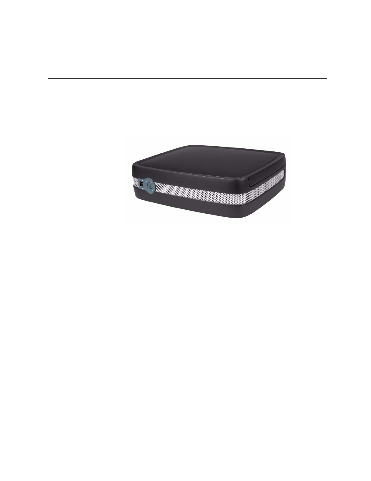
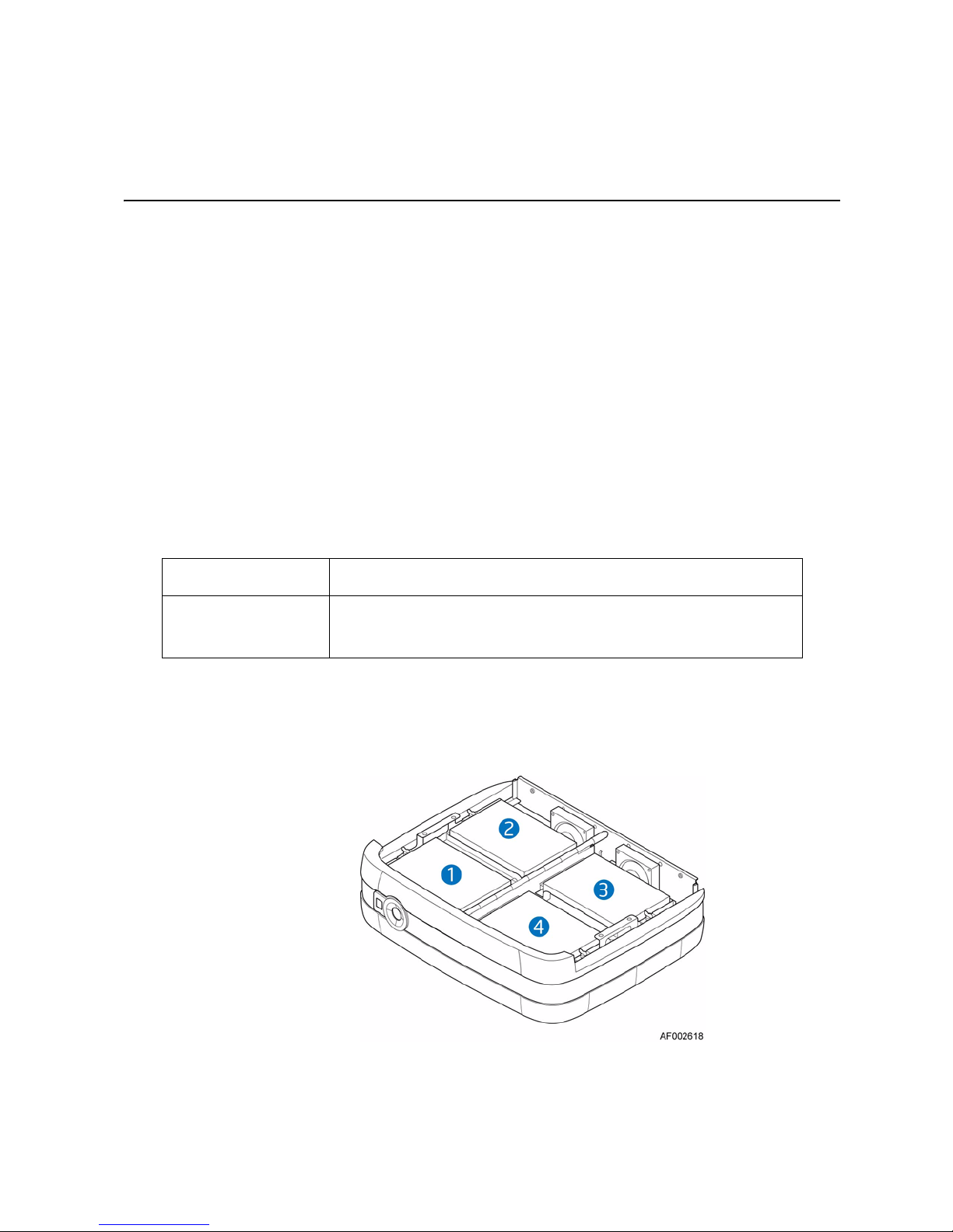
The Intel® Entry Storage System SS4200-E is a custom enclosure that can house up to
four low-profile (1-in high), 1.5/3.0 Gb/s, 3.5-in form factor SATA disk drives. Each
individual drive is field replaceable.
®
Figure 1 shows a front view of the Intel
Figure 1. Intel
®
Entry Storage System SS4200-E.
Entry Storage System SS4200-E
Enclosure Core Product
The Intel® Entry Storage System SS4200-E design concept is based on a custom
enclosure and (as supplied) consists of:
• An enclosure chassis with:
— A Front Panel
— An integral Rear Panel
— A 250-W power supply
• Two high-speed, single-rotor fans, which are individually pluggable
• Four drive carrier modules
Intel® Entry Storage System SS4200-E User Guide 1
Page 16
Storage System Features
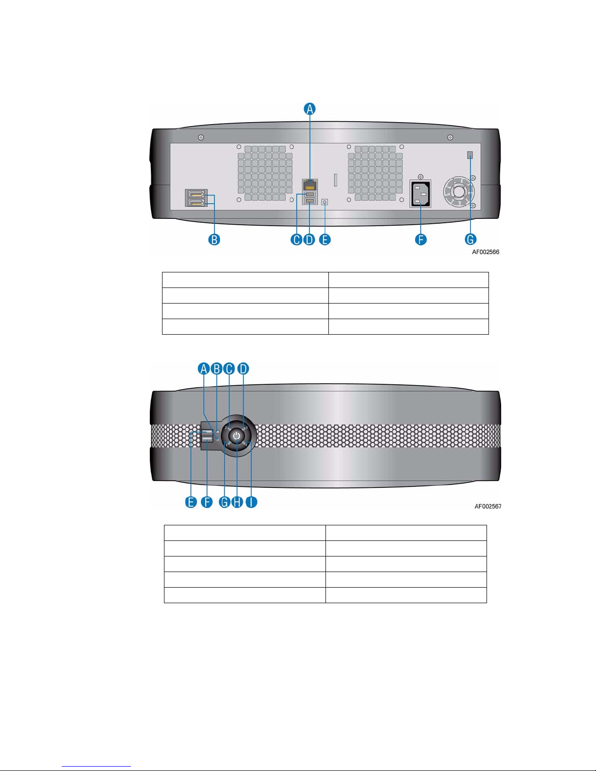
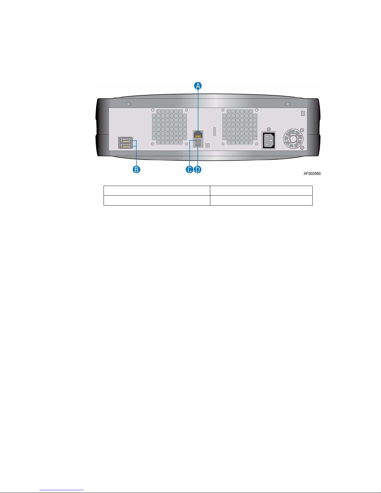
A. NIC Port (1 Gb) E. Reset Button
B. e-SATA Port F. A/C Power
C. USB Port 2 G. Chassis Cable Lock
D. USB Port 3
Figure 2. Rear View
A. NIC Activity LED F. USB Port 1
B. Disk Drive Activity LED G. Disk Drive 1 Status LED
C. Disk Drive 2 Status LED H. Power/Status Push-button
D. Disk Drive 3 Status LED I. Disk Drive 4 Status LED
E. USB Port 0
Figure 3. Front View
2 Intel® Entry Storage System SS4200-E User Guide
Page 17
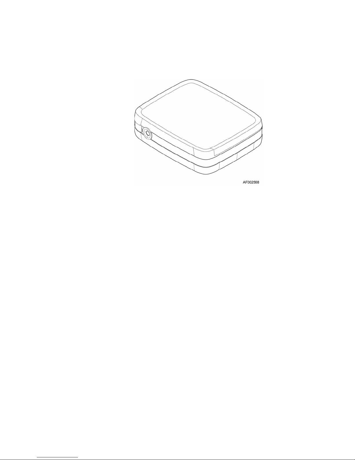
Chassis
Storage System Features
Figure 4. Chassis
The chassis consists of a sheet metal assembly containing an integrated printed circuit
board (PCB) and plastic skin.
A top cover on the chassis provides access to the cooling fans, system board, power
supply and hard drives.
Important: The chassis cover should only be removed by qualified service personnel as it provides
access to a service area. Upon replacement, the cover MUST be secur ed by tightening the
captive screws at the upper corners of the rear of the chassis.
System Board Subsystem
The system board sub-system consists of:
• An Intel® designed system board
• A single PCI-e slot intended for debug purposes only
Intel® Entry Storage System SS4200-E User Guide 3
Page 18
Storage System Features
System Board I/O Panel
A. NIC Port (1 Gb) C. USB Port 2
B. e-SATA Port D. USB Port 3
Connectors
NIC LEDs
Figure 5. System Board I/O Panel Connectors
The following connectors are present on the system board I/O panel:
• One RJ-45 port - NIC 1 (1 Gb)
• One e-SATA port
• Two USB ports: 2 and 3
Two LEDS at the right and left of the NIC port provide information on NIC status.
4 Intel® Entry Storage System SS4200-E User Guide
Page 19
System Board Layout
Storage System Features
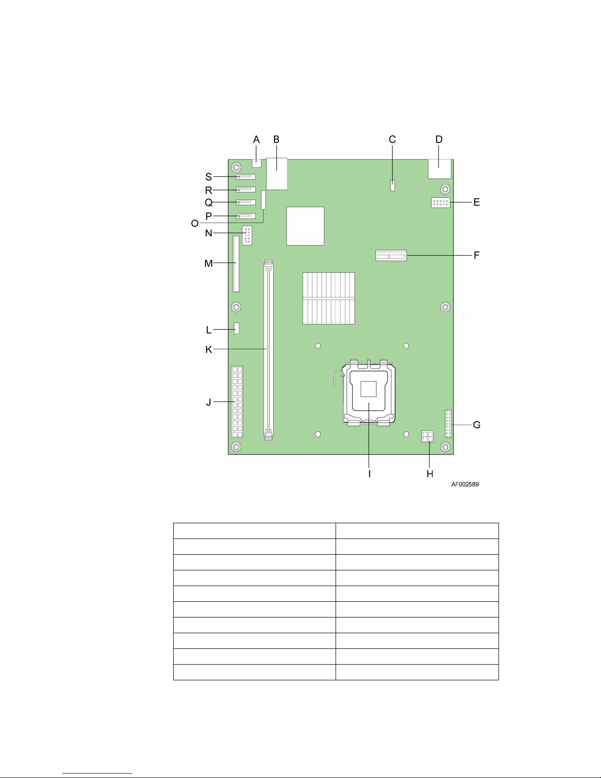
A. Reset / Recovery Button K. DIMM Slot
B. LAN Port / USB Port L. Left Cooling Fan Connector
C. Right Cooling Fan Connector M. IDE DOM Connector
D. e-SATA Connectors N. USB Header
E. RS-232 Debug Port O. CMOS Battery
F. PCI-e Debug Port P. SATA 4 Connector
G. Front Panel Header Q. SATA 3 Connector
H. CPU Power Connector R. SATA 2 Connector
I. CPU Processor S. SATA 1 Connector
J. Main Power Connector
Intel® Entry Storage System SS4200-E User Guide 5
Figure 6. System Board Layout
Page 20
Storage System Features
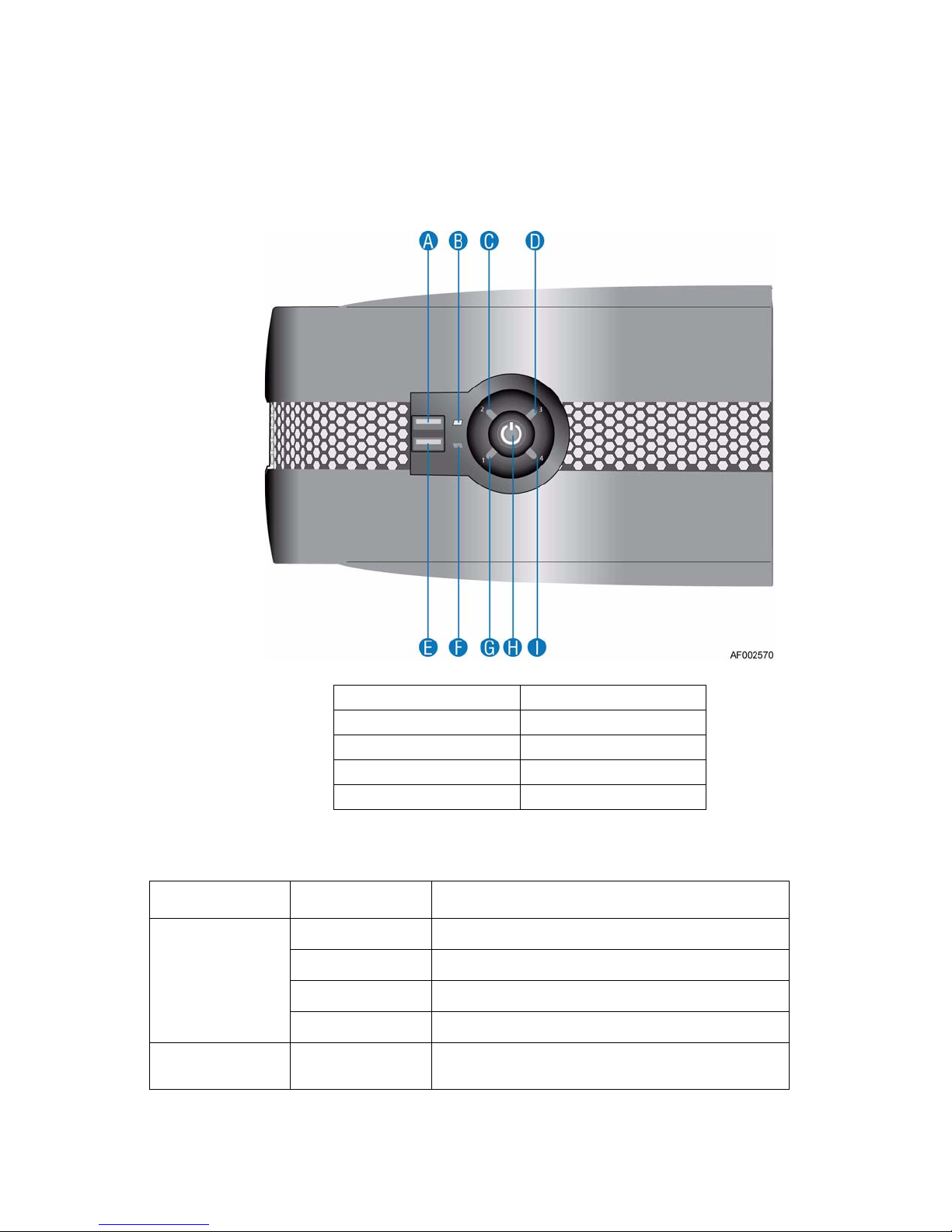
Front Panel
A Front Panel, consisting of two USB ports, six LEDs and one lighted power/status pushbutton, is present on the front of the enclosure.
Important: The Front Panel is an integral p art of the enclosure assembly and is not field replaceable.
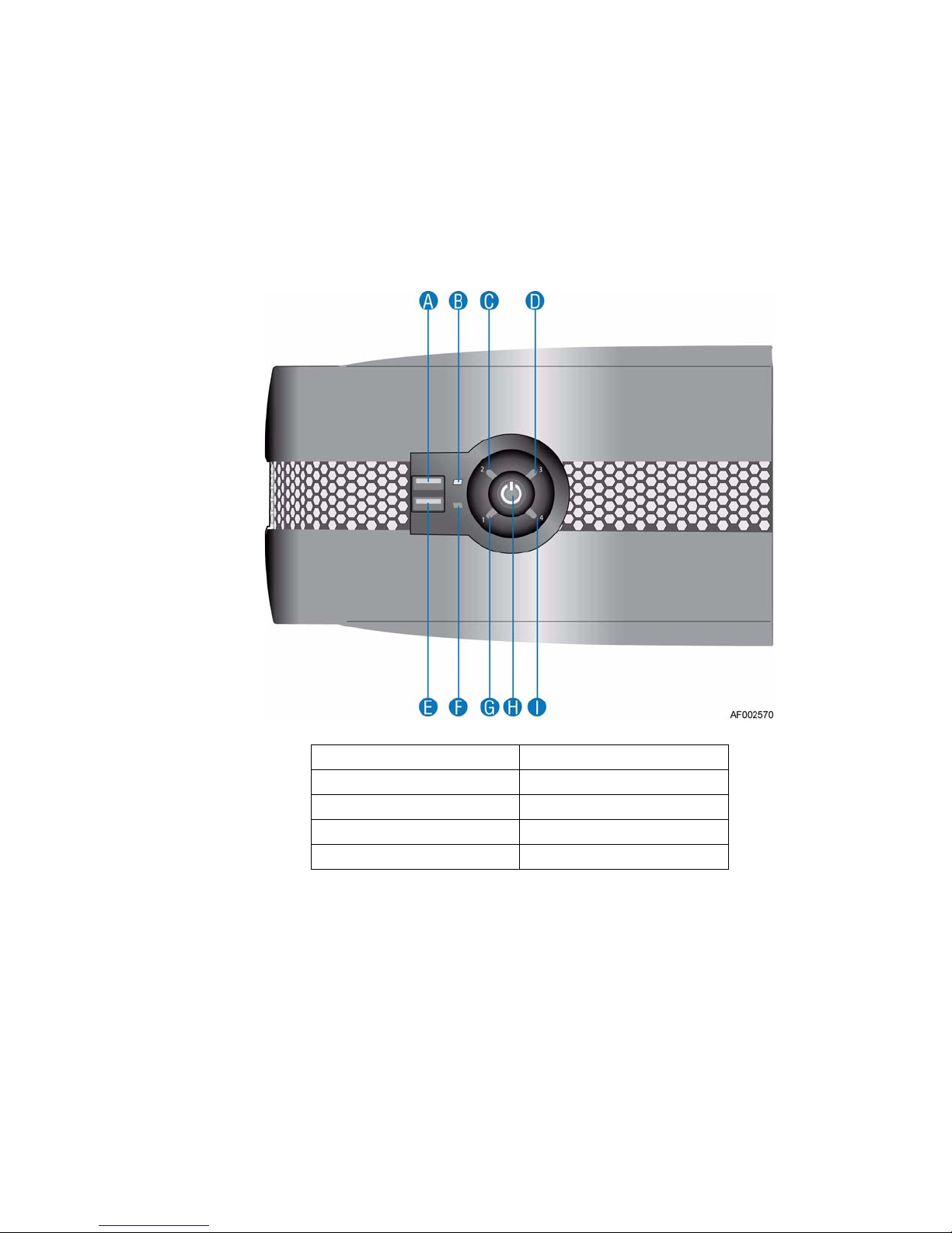
A. USB Port 0 B. Disk Drive Activity LED
C. Disk Drive 2 Status LED D. Disk Drive 3 Status LED
E. USB Port 1 F. NIC Activity LED
G. Disk Drive 1 Status LED H. Power/Status Push-button
I. Disk Drive 4 Status LED
Figure 7. Front Panel Components
For a full description of Front Panel LED and switch functions, see “Front Panel LEDs
and Switches” on page 12.
Rear Panel
Important: The Rear Panel is an integral part of the chassis assembly and is not field replaceable.
A Rear Panel, consisting of a network connector, a dual e-SATA port and two USB
connectors, is present on the rear of the chassis.
6 Intel® Entry Storage System SS4200-E User Guide
Page 21

Power Supply
AC-DC power is provided by an enclosed power supply with specific load capability,
mechanical packaging and output loom to suit this product.
The power supply voltage operating ranges are nominally 100V - 240V AC, selected
automatically.
Power Supply Output Loom
The power supply output loom provides the following outputs:
• P1 system board main power connector (24 pin)
• P2 processor power connector (4 pin)
• P3, P4, P6 and P7 peripheral power connector (4 x 5-pin)
• P5 IDE DOM connector (4 pin)
Storage System Features
Cooling Fans
Two high-speed single-rotor fans are located at the rear of the enclosure.
Airflow is front to rear with cooling air being drawn across the drives, through the fans
and exiting the rear of the chassis. Perforations at the rear of the chassis allow cooling air
to flow over the processor heatsink and system board.
Drive Retention Assembly
The drive retention assembly consists of a “gull wing” design assembly mounted via a
pivot point in the center of the chassis. Each side of the drive retention assembly can
house two low-profile, 1.0-inch high, 3.5-inch form factor SATA disk drives.
Each disk drive is retained in a custom retention device which affords the drive with
maximum physical protection and minimizes rotational vibration.
Disk Drive Status Indicator
Four status LEDs on the Front Panel (one for each SATA disk drive) provide a visual
indication of hard drive functionality. See “Front Panel Components” on page 6 for the
location of the disk drive status LEDs. See “Front Panel LED States” on page 12 for a
description of disk drive status LED states.
Intel® Entry Storage System SS4200-E User Guide 7
Page 22
Storage System Features
Spare Parts and Accessories
The following replaceable parts are available for the Intel® Entry Storage System SS4200E.
Table 1. Spare Parts and Accessories
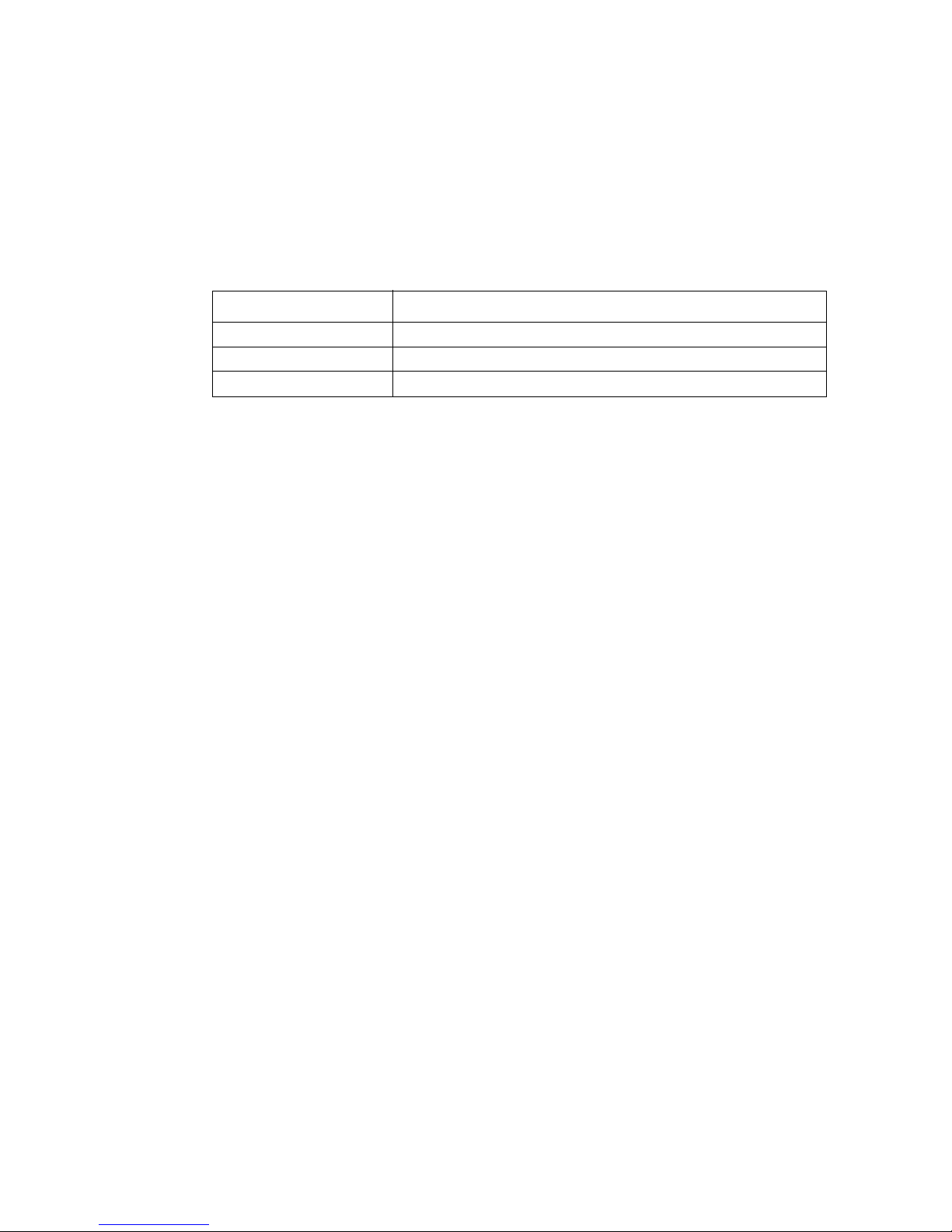
Part Number Description
FXXSS4200EPSU Power supply
FXXSS4200EFAN Cooling fan
FXXSS4200ESCR RVR (Rotational Vibration Reduction) screw
8 Intel® Entry Storage System SS4200-E User Guide
Page 23
2 Getting Started
In this chapter, you are shown how to setup your Intel® Entry Storage System SS4200-E.
Caution: When connecting up the Intel
supplied or a power cord which matches the specific voltage and frequency of your
country.
®
Entry Storage System SS4200-E, use only the power cord
Planning Your Installation
Important: Installation procedures should be performed by service personnel only.
®
Before beginning installation of your Intel
yourself with the configuration requirements listed in the following table.
Table 2. Configuration Requirements
Component Location
Drive Retention
Assembly
Number of minimum required disk drives is dependent on type of operating
system and storage management software installed. See your software
documentation for disk drive requirements.
Entry Storage System SS4200-E, familiarize
Disk Drive Numbering Convention
The disk drive numbering convention in the drive retention assembly is as follows:
Figure 8. Disk Drive Numbering Convention
Intel® Entry Storage System SS4200-E User Guide 9
Page 24

Getting Started
Enclosure Installation Prerequisites
Caution: Ensure that you have fitted and checked a suitable anti-static wrist band or ankle strap
and observe all conventional ESD precautions when handling system components. Avoid
contact with the system board and other internal components.
Preparation of Site and Host Server
Before beginning, make sure that the site where you intend to set up and use your Intel
Entry Storage System SS4200-E has standard AC power available from an independent
source or a power distribution unit with a UPS (universal power supply).
Adequate airflow around all grill surfaces of the storage system must be provided to
ensure proper cooling of the system.
Planning and Configuring Your Installation
Refer to “Planning Your Installation” on page 9 for information on overall system
configuration requirements.
Refer to the Quick Sta rt User’s Guide that shipped with your system for instructions on
initially setting up the Intel
For third-party software solutions, refer to the documentation provided by your vendor for
installing operating systems or additional hardware.
®
Entry Storage System SS4200-E.
Power Cord Connection
Caution: The power connection must always be disconnected prior to removing the power supply
from the enclosure.
®
See “Connecting the Power Cord” on page 31 for instructions on connecting your storage
system to a power source.
Grounding Checks
The Intel® Entry Storage System SS4200-E must only be connected to a power source that
has a safety electrical earth connection.
Before powering on, the earth connection to the system should be checked by a qualified
technician.
10 Intel® Entry Storage System SS4200-E User Guide
Page 25

3 Operation
Before You Begin
Before powering up the Intel® Entry Storage System SS4200-E ensure that all disk drives
are correctly installed and locked down.
Power On
Caution: Do not operate the Intel® Entry Storage System SS4200-E unt il the ambient temperatur e is
within the specified operating range. If the drives have been recently installed, ensure they
have had time to acclimate before operating them.
Note: See “Front Panel LEDs and Switches” on page 12 for details on Front Panel LEDs and
related fault conditions.
Apply AC main power to power on the system.
The Power/Status push-button on the Front Panel will light up a constant blue once power
is activated and system is operational. The disk drive motors will also start running.
Starting the Drives
All drives in the chassis should automatically start their motors during power on. If this
does not occur then there may be a power problem.
Disk Drive Status LEDs
Each disk drive has a corresponding status LED on the Front Panel. See “Front Panel LED
States” on page 12 for information on illumination states. See “Disk Drive Numbering
Convention” on page 9 for positional order of disk drives.
Intel® Entry Storage System SS4200-E User Guide 11
Page 26
Operation
Front Panel LEDs and Switches
The Front Panel LED and push-button states are defined in Table 3.
A. USB Port 0 B. Disk Drive Activity LED
C. Disk Drive 2 Status LED D. Disk Drive 3 Status LED
E. USB Port 1 F. NIC Activity LED
G. Disk Drive 1 Status LED H. Power Button
I. Disk Drive 4 Status LED
Figure 9. Front Panel Components
Table 3. Front Panel LED States
LED Color Definition
Power/Status Pushbutton LED
Disk Drive Activity
LED
Constant blue Power present. System is booted and operational.
Flashing blue System is in process of booting up.
Amber A critical or non-recoverable condition has occurred.
Off System is off. No power present.
Constant blue Activity is present on any disk drive.
12 Intel® Entry Storage System SS4200-E User Guide
Page 27
Table 3. Front Panel LED States
NIC Activity LED Constant blue Link is active.
Flashing blue Link activity is present.
Operation
Disk Drive Status
LED
Constant blue Drive is available
Constant amber Disk drive fault has occurred.
Flashing amber Disk drive is rebuilding.
Off Disk drive is not present.
Table 4. Front Panel Push-button Functionality
Push-button State Definition
On/Off Function of this button is dependent on the enclosure status.
If system is connected to power source but not operating: Press button
to activate and commence boot process.
If system is operating:
• Depress push-button for <3 seconds to shut down system gracefully.
• Depress push-button for >4 seconds to perform a hard shut down of
system.
Power Down
Note: Refer to your storage software documentation for any power down procedures before
powering down the system.
To power down the system, either:
• Press the Power/Status push-button on the Front Panel for less than 3 seconds to
perform a graceful shut down,
or
• Press the Power/Status push-button on the Front Panel for greater than 4 seconds to
perform a hard shut down.
Intel® Entry Storage System SS4200-E User Guide 13
Page 28

Operation
Reset/Recovery
Under normal operation, the storage system has the following boot order:
1. Internal hard drives (SATA)
2. If present, internal ATA interface (DOM)
System boot functionality is modified (as per the following table) if the reset/recovery
button is depressed during system power on.
Table 5. Reset/Recovery Functionality during Power-on
Button Location Description
Reset/Recovery Rear of storage
device (see Figure 2
on page 2 for
location of button)
On a Microsoft* Windows Home Server-based storage
device, if the button is depressed during system poweron, the boot order is modified by the BIOS as follows:
1. USB flash device
2. USB CD/DVD device
3. ATA interface
On a storage device that is NOT running Microsoft*
Windows Home Server software, if pressed, the system
will be reset to factory defaults (i.e., IP and password are
set to default values).
14 Intel® Entry Storage System SS4200-E User Guide
Page 29

4 Hardware Installations and
Upgrades
This chapter provides instructions for removing, installing, and replacing storage system
components in your Intel
Caution: When connecting the Intel
the power cord that shipped with the system, or match the power cor d specifications listed
under “Power Cord” on page 56.
Caution: It is recommended that you fit and check a suitable anti-static wristband and conductive
foam pad and observe all conventional ESD precautions when handling storage system
components.
®
Entry Storage System SS4200-E.
®
Entry Storage System SS4200-E to a power sour ce, use either
Before You Begin
Before working with your storage system, review the important ESD precaution and
safety information listed in “Safety Information” on page 85.
Tools and Supplies Needed
• Phillips* (cross head) screwdriver (#1 bit and #2 bit)
• Needle-nosed pliers
• Anti-static wrist strap and conductive foam pad (recommended)
System References
All references to left, right, front, top, and bottom assume the reader is facing the front of
the storage system.
Installing Feet
The Intel® Entry Storage System SS4200-E ships with no feet installed. Y ou can configure
the system for either horizontal or vertical orientation.
Note: Feet should be installed for system stability and rotational vibration dampening.
Intel® Entry Storage System SS4200-E User Guide 15
Page 30
Hardware Installations and Upgrades
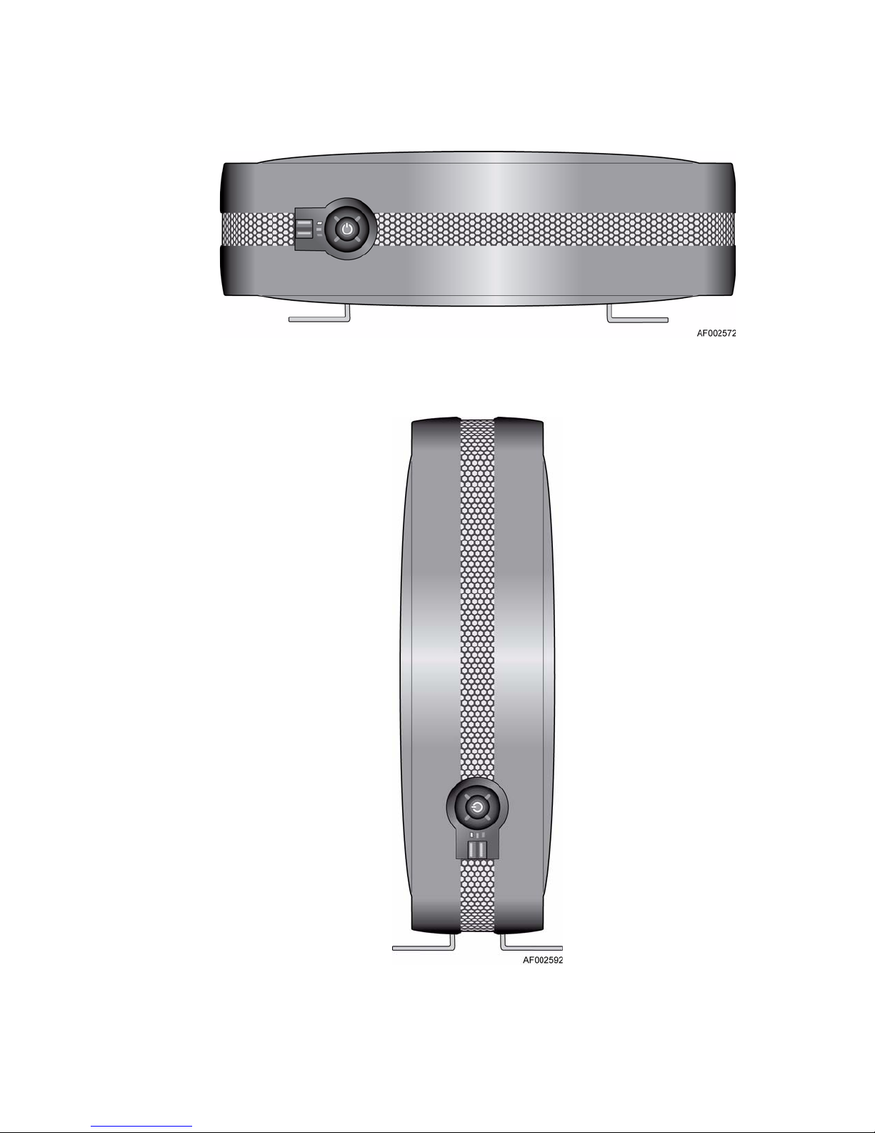
Figure 10. System in Horizontal Configuration
16 Intel® Entry Storage System SS4200-E User Guide
Figure 11. System in Vertical Configuration
Page 31

Initial Setup
For Horizontal Configuration: Remove feet from package. Insert feet into horizontal
position slots in chassis (see letter “A” in the following figure). Feet are keyed to fit only
one way in slots.
Hardware Installations and Upgrades
Figure 12. Orienting Feet for Initial Horizontal Configuration
For Vertical Configuration
: Remove feet from package. Insert feet into vertical position
slots in chassis (see letter “A” in the following figure). Feet are keyed to fit only one way.
Figure 13. Orienting Feet for Initial Vertical Configuration
Intel® Entry Storage System SS4200-E User Guide 17
Page 32

Hardware Installations and Upgrades
Converting Feet from Horizontal to Vertical Configuration
1. Remove feet from horizontal position slots in chassis (see letter “A” in the following
figure) and insert into vertical position slots (see letter “B”). Feet are keyed to fit only
one way in slots.
Figure 14. Converting Feet from Horizontal to Vertical Configuration
18 Intel® Entry Storage System SS4200-E User Guide
Page 33

Hardware Installations and Upgrades
Converting Feet from Vertical to Horizontal Configuration
1. Remove feet from vertical position slots in chassis (see letter “A” in the following
figure) and insert into horizontal position slots (see letter “B”).
Figure 15. Converting Feet from Vertical to Horizontal Configuration
Removing or Installing the Enclosure Cover
Warning: The enclosure cover must only be removed by a qualified service person as it provides
access to a service area. Potential hazards include:
— Energy hazard
— Rotating fans
— Hot surfaces
— Access to power supply unit openings
Upon replacement, the cover MUST be secured by tightening the captive screws at the
rear of the system. If needed, a Phillips* screwdriver can be used to tighten the screws.
Intel® Entry Storage System SS4200-E User Guide 19
Page 34

Hardware Installations and Upgrades
Removing the Enclosure Cover
1. Observe all safety and ESD precautions listed in “Safety Information” on page 85.
2. Loosen the two captive screws at the rear of the system (see letter “A” in the
following figure). Slide the enclosure cover to the rear (see letter “B”) and then lift
upward to remove from the system.
20 Intel® Entry Storage System SS4200-E User Guide
Figure 16. Removing Enclosure Cover
Page 35

Installing the Enclosure Cover
1. Observe all safety and ESD precautions listed in “Safety Information” on page 85.
2. Align the enclosure cover over the sides of the system (see letter “A” in the following
figure). Slide the enclosure cover toward the front of the system (see letter “B”).
Secure the enclosure cover to the system by tightening the captive screws at the rear
of the system (see letter “C”).
Hardware Installations and Upgrades
Intel® Entry Storage System SS4200-E User Guide 21
Figure 17. Installing Enclosure Cover
Page 36

Hardware Installations and Upgrades
Installing a Hard Drive
1. Observe all safety and ESD precautions listed in “Safety Information” on page 85.
2. Turn off all peripheral devices connected to the storage system. Power down the
storage system.
3. Disconnect the AC power cord.
4. Remove the enclosure cover. For instructions, see “Removing the Enclosure Cover”
on page 20.
5. Remove the four RVR (rotational vibration reduction) screws from the drive retention
bracket. See letter “A” in the following figure.
Note: RVR screws may be removed either prior to lifting t he drive retention bracket
or after lifting the drive retention bracket.
Note: Spare RVR screws are located at the front of the system, inside, by the front
panel board.
22 Intel® Entry Storage System SS4200-E User Guide
Figure 18. Removing RVR Screws
Page 37

Hardware Installations and Upgrades
6. Loosen the captive screw at the front of the drive retention bracket (see letter “A” in
the following figure) and lift up the bracket (see letter “B”).
Figure 19. Unlatching Drive Retention Bracket
7. Remove new hard drive from packaging. Attach four RVR screws to the hard drive
(see letter “A” in the following figure).
Figure 20. Attaching RVR Screws to Hard Drive
Intel® Entry Storage System SS4200-E User Guide 23
Page 38

Hardware Installations and Upgrades
8. Install hard drive into drive retention device.
Figure 21. Installing Hard Drive into Drive Tray
9. Connect the SATA cable from the system board (see letter “A” in the following
figure). Connect the power cable from the power supply (see letter “B”).
Note: You may connect the cables prior to placing the hard drive in the lower drive
retention tray OR you may first secure the hard drive in the lower drive
retention tray, flip the drive assembly over, and then connect the cables.
Figure 22. Connect SATA and Power Cables
24 Intel® Entry Storage System SS4200-E User Guide
Page 39

Hardware Installations and Upgrades
10. Lower the drive retention bracket (see letter “A” in the following figure) and tighten
the captive screw (see letter “B”).
Figure 23. Latching Drive Retention Bracket
11.Re-install the enclosure cover. For instructions, see “Installing the Enclosure Cover”
on page 21.
12. Reconnect all peripheral devices and the AC power cord. Power up the storage
system.
Replacing a Power Supply
Warning: Do not remove covers from the power supply. Danger of electric shock exists inside.
Return the power supply to your supplier for repair.
Warning: Removal of a power supply must only be performed by a qualified service person.
Potential hazards include:
— Energy hazard
— Hot surfaces
— Access to power supply openings
Caution: Before performing any maintenance on the system, back up the data. Follow the
instructions in the operating system manual or third-party software documentation for
shutting down the system.
Warning: Upon completion of power supply replacement, the enclosure cover MUST be properly re-
installed to ensure adequate cooling of the system.
1. Check new power supply for damage. If any damage exists, return power supply to
vendor for replacement.
2. Observe all safety and ESD precautions listed in “Safety Information” on page 85.
Intel® Entry Storage System SS4200-E User Guide 25
Page 40

Hardware Installations and Upgrades
3. Turn off all peripheral devices connected to the storage system. Power down the
storage system.
4. Disconnect the AC power cord.
5. Remove the enclosure cover. For instructions, see “Removing the Enclosure Cover”
on page 20.
6. Lift the left side of the drive tray assembly (see letter “A” in the following figure).
Figure 24. Lifting Left Side of Drive Tray Assembly
7. Remove the airflow baffle. This may require compressing the airflow baffle slightly to
slide it out of the two chassis tabs at each end of the baffle.
Figure 25. Removing Airflow Baffle
26 Intel® Entry Storage System SS4200-E User Guide
Page 41

Hardware Installations and Upgrades
8. Disconnect the power cables from all installed hard drives (see letter “A” in the
following figure). Disconnect the power cables from the main power and CPU power
connectors on the system board (see letter “B”). Remove the three screws at the rear
of chassis securing the power supply to the system (see letter “C”). Slide the power
supply forward (see letter “D”) and then lift out of the system (see letter “E”).
Note: You may need to remove cable ties securing power cables to the middle of the
drive tray assembly.
Note: Drive tray assembly removed for illustrative purposes.
Intel® Entry Storage System SS4200-E User Guide 27
Figure 26. Removing Faulty Power Supply
Page 42

Hardware Installations and Upgrades
9. Remove the retention tab from the old power supply (see letter “A” in the following
figure).
Figure 27. Removing Retention Tab from Old Power Supply
10. Install the retention tab on new power supply.
28 Intel® Entry Storage System SS4200-E User Guide
Page 43

Hardware Installations and Upgrades
11.Position the new power supply in the system (see letter “A” in the following figure).
Ensure that the retention tab slides into slot in chassis (see letter “B”). Secure new
power supply to the system with the three screws previously removed (see letter “C”).
Connect a power cable to each of the installed hard drives (see letter “D”). Connect
power cables to the main power and CPU power connectors on the system board (see
letter “E”).
Note: Holes are located in the lower portion of the drive tray assembly for securing
cable ties.
Note: Drive tray assembly removed for illustrative purposes.
Intel® Entry Storage System SS4200-E User Guide 29
Figure 28. Installing New Power Supply
Page 44

Hardware Installations and Upgrades
12. Replace the airflow baffle. Ensure that the airflow baffle is securely inserted into the
two chassis tabs at each end of the baffle. This may require compressing the airflow
baffle slightly to slide it into the chassis tabs.
Figure 29. Replacing Airflow Baffle
13. Return the left side of the drive tray assembly to its operational position (see letter
“A” in the following figure).
Figure 30. Lowering Left Side of Drive Tray Assembly
14. Re-install the enclosure cover. For instructions, see “Installing the Enclosure Cover”
on page 21.
15. Reconnect all peripheral devices and the AC power cord. Power up the storage
system.
30 Intel® Entry Storage System SS4200-E User Guide
Page 45

Hardware Installations and Upgrades
Connecting the Power Cord
Caution: Power connection must always be disconnected prior to removal of a power supply from
the system.
1. Observe all safety and ESD precautions listed in “Safety Information” on page 85.
2. Attach a power cord to the rear connector on the power supply.
Grounding Checks
This product must only be connected to a power source with a safety electrical earth
connection.
Prior to switching on, ensure that the earth connection has been checked by an electrical
engineer qualified in local and national electrical standards.
Figure 31. Connecting Power Cord
Intel® Entry Storage System SS4200-E User Guide 31
Page 46

Hardware Installations and Upgrades
Replacing a Cooling Fan
Warning: Removal of a cooling fan must only be performed by a qualified service person. Potential
hazards include:
— Energy hazard
—Hot surfaces
— Access to power supply openings
Caution: Before performing any maintenance on the system, back up the data. Follow the
instructions in the operating system manual or third-party software documentation for
shutting down the system.
Warning: Upon completion of cooling fan replacement, the enclosure cover MUST be properly re-
installed to ensure adequate cooling of the system.
1. Check the new fan for damage. Do not install it if there are any visible signs of
damage. Return to vendor for replacement.
2. Observe all safety and ESD precautions listed in “Safety Information” on page 85.
3. Turn off all peripheral devices connected to the storage system. Power down the
storage system.
4. Disconnect the AC power cord.
5. Remove the enclosure cover. For instructions, see “Removing the Enclosure Cover”
on page 20.
32 Intel® Entry Storage System SS4200-E User Guide
Page 47

Hardware Installations and Upgrades
To replace the right cooling fan:
6. Lift up the right side of the drive tray assembly (see letter “A” in the following
figure).
Figure 32. Lifting Right Side of Drive Tray Assembly
7. Remove the two screws securing the fan guard to the rear of the chassis (see letter “A”
in the following figure). Remove the fan guard (see letter “B”).
Figure 33. Removing Right Fan Guard
Intel® Entry Storage System SS4200-E User Guide 33
Page 48

Hardware Installations and Upgrades
8. Disconnect the power cable from the system board (see letter “A” in the following
figure). Disengage the cooling fan from the rear of chassis by sliding cooling fan
upward and out of keyhole slots in the chassis (see letter “B”). Remove the cooling
fan from the system (see letter “C”).
Figure 34. Removing Right Cooling Fan from System
34 Intel® Entry Storage System SS4200-E User Guide
Page 49

Hardware Installations and Upgrades
9. Position the new cooling fan in the system (see letter “A” in the following figure).
Slide rubber mounting grommets on back of the cooling fan into corresponding
keyhole slots in the chassis (see letter “B”). Connect the fan cable to the system board
(see letter “C”).
Figure 35. Installing New Right Cooling Fan
10. Re-install the fan guard (see letter “A” in the following figure). Secure the fan guard
to the rear of the chassis with the two screws previously removed (see letter “B”).
Figure 36. Re-installing Right Fan Guard
Intel® Entry Storage System SS4200-E User Guide 35
Page 50

Hardware Installations and Upgrades
11.Return the right side of the drive tray assembly to its operational position (see letter
“A” in the following figure).
Figure 37. Lowering Right Side of Drive Tray Assembly
12. Re-install the enclosure cover. For instructions, see “Installing the Enclosure Cover”
on page 21.
13. Reconnect all peripheral devices and the AC power cord. Power up the storage
system.
36 Intel® Entry Storage System SS4200-E User Guide
Page 51

Hardware Installations and Upgrades
To replace left cooling fan:
14. Lift up the left side of the drive tray assembly (see letter “A” in the following figure).
Figure 38. Lifting Left Side of Drive Tray Assembly
15. Remove the two screws securing the fan guard to the rear of the chassis (see letter “A”
in the following figure). Remove the fan guard (see letter “B”).
Intel® Entry Storage System SS4200-E User Guide 37
Figure 39. Removing Left Fan Guard
Page 52

Hardware Installations and Upgrades
16. Disconnect the power cable from the system board (see letter “A” in the following
figure). Disengage the cooling fan from rear of chassis by sliding the cooling fan
upward and out of keyhole slots in chassis (see letter “B”). Remove the cooling fan
from the system (see letter “C”).
Figure 40. Removing Left Cooling Fan
38 Intel® Entry Storage System SS4200-E User Guide
Page 53

Hardware Installations and Upgrades
17. Position the new cooling fan in the system (see letter “A” in the following figure).
Slide rubber mounting grommets on back of cooling fan into corresponding keyhole
slots in chassis (see letter “B”). Connect the fan cable to the system board (see letter
“C”).
Figure 41. Installing New Left Cooling Fan
Intel® Entry Storage System SS4200-E User Guide 39
Page 54

Hardware Installations and Upgrades
18. Re-install the fan guard (see letter “A” in the following figure). Secure the fan guard
to the rear of the chassis with the two screws previously removed (see letter “B”).
Figure 42. Re-installing Left Fan Guard
19. Return the left side of the drive tray assembly to its operational position (see letter
“A” in the following figure).
Figure 43. Lowering Left Side of Drive Tray Assembly
20. Re-install the enclosure cover. For instructions, see “Installing the Enclosure Cover”
on page 21.
21. Reconnect all peripheral devices and the AC power cord. Power up the storage
system.
40 Intel® Entry Storage System SS4200-E User Guide
Page 55

Replacing Memory
1. Observe all safety and ESD precautions listed in “Safety Information” on page 85.
2. Turn off all peripheral devices connected to the storage system. Power down the
storage system.
3. Disconnect the AC power cord.
4. Remove the enclosure cover. For instructions, see “Removing the Enclosure Cover”
on page 20.
5. Lift the right side of the drive tray assembly (see letter “A” in the following figure).
Hardware Installations and Upgrades
Figure 44. Lifting Right Side of Drive Tray Assembly
Intel® Entry Storage System SS4200-E User Guide 41
Page 56

Hardware Installations and Upgrades
6. Locate the DIMM socket (see the following figure). Push the clips at each end of the
DIMM socket outward to the open position (see letter “A”). Holding the DIMM by its
edges, lift it from the socket (see letter “B”). Store the DIMM in an anti-static
package.
Figure 45. Locating DIMM Socket and Removing Memory
42 Intel® Entry Storage System SS4200-E User Guide
Page 57

Hardware Installations and Upgrades
7. Install the new DIMM. Ensure the clips at each end of the DIMM socket are pushed
outward to the open position (see letter “A” in the following figure). Holding the
DIMM by its edges, remove it from its anti-static package. Position the DIMM above
the socket. Align the notch on the bottom edge of the DIMM with the key in the
DIMM socket. The arrow for letter “B” is pointing to the key in the socket. Insert the
bottom edge of the DIMM into the socket. When the DIMM is inserted, push down on
the top edge of the DIMM until the retaining clips snap into place (see letter “C”).
Make sure the clips latch firmly in place (see letter “D”).
Figure 46. Installing New DIMM
8. Return the right side of the drive tray assembly to its operational position (see letter
“A” in the following figure).
Figure 47. Lowering Right Side of Drive Tray Assembly
9. Re-install the enclosure cover. For instructions, see “Installing the Enclosure Cover”
on page 21.
10. Reconnect all peripheral devices and the AC power cord. Power up the storage
system.
Intel® Entry Storage System SS4200-E User Guide 43
Page 58

Hardware Installations and Upgrades
Replacing the CMOS Battery
The lithium CMOS battery on the system board powers the RTC in the absence of power.
When the battery starts to weaken, it loses voltage, and the system settings stored in
CMOS RAM (for example, the date and time) may be wrong. Contact your customer
service representative or dealer for a list of approved replacement batteries.
Warning: Danger of explosion if battery is incorrectly replaced. Replace only with the same or
equivalent type recommended by the equipment manufacturer. Discard used batteries
according to manufacturer's instructions.
Advarsel: Lithiumbatteri - Eksplosionsfare ved fejlagtig håndtering. Udskiftning må kun ske med
batteri af samme fabrikat og type. Levér det brugte batteri tilbage til leverandøren.
Varning: Explosionsfara vid felaktigt batteribyte. Använd samma batterityp eller en ekvivalent typ
som rekommenderas av apparattillverkaren. Kassera använt batteri enligt fabrikantens
instruktion.
Varoitus: Paristo voi räjähtää, jos se on virheellisesti asennettu. Vaihda paristo ainoastaan
laitevalmistajan suosittelemaan tyyppiin. Hävitä käytetty paristo valmistajan ohjeiden
mukaisesti.
1. Observe all safety and ESD precautions listed in “Safety Information” on page 85.
2. Turn off all peripheral devices connected to the storage system. Power down the
storage system.
3. Disconnect the AC power cord.
4. Remove the enclosure cover. For instructions, see “Removing the Enclosure Cover”
on page 20.
5. Lift the right side of the drive tray assembly (see letter “A” in the following figure).
Figure 48. Lifting Right Side of Drive Tray Assembly
44 Intel® Entry Storage System SS4200-E User Guide
Page 59

Hardware Installations and Upgrades
6. Locate the CMOS battery. Use a finger to pull the lever away from the top of the
battery until it clears the battery. Use caution so you do not bend the lever. Lift the
battery from the socket.
Figure 49. Locating and Removing the CMOS Battery
7. Dispose of the battery according to local ordinance.
8. Remove the new battery from its package.
9. Being careful to observe the correct polarity, insert the replacement battery into the
battery socket. The “+” side of the battery must face the lever side of the battery
socket, toward the add-in card slots.
Intel® Entry Storage System SS4200-E User Guide 45
Page 60

Hardware Installations and Upgrades
10. Return the right side of the drive tray assembly to its operational position (see letter
“A” in the following figure).
Figure 50. Lowering Right Side of Drive Tray Assembly
11.Re-install the enclosure cover. For instructions, see “Installing the Enclosure Cover”
on page 21.
12. Reconnect all peripheral devices and the AC power cord. Power up the storage
system.
13. Run the BIOS Setup utility to restore the configuration settings to the real-time clock.
46 Intel® Entry Storage System SS4200-E User Guide
Page 61

Hardware Installations and Upgrades
Boot Drive
The Intel® Entry Storage System SS4200-E has two options for loading operating systems
or storage software.
If the system is running an Intel storage management stack, it will contain an IDE DOM
(disk on module) on the system board. This DOM contains the operating system and any
management software. IDE DOMs require power to be provided by the storage system
using the P4 power cable that is provided as part of the power supply harness. The P4
power cable needs to be attached to the power adapter cable that came with your IDE
DOM.
If your system does not contain an IDE DOM, refer to the documentation provided by
your third-party vendor(s) for instructions on installing storage software.
Replacing an IDE DOM (if present)
Caution: Before performing any maintenance on the system, back up the data.
Note: Refer to your vendor’s documentation for procedures on replacing storage system
software.
1. Observe all safety and ESD precautions listed in “Safety Information” on page 85.
2. Turn off all peripheral devices connected to the storage system. Power down the
storage system.
3. Disconnect the AC power cord.
4. Remove the enclosure cover. For instructions, see “Removing the Enclosure Cover”
on page 20.
5. Lift the left side of the drive tray assembly (see letter “A” in the following figure).
Intel® Entry Storage System SS4200-E User Guide 47
Figure 51. Lifting Left Side of Drive Tray Assembly
Page 62

Hardware Installations and Upgrades
6. Locate the IDE connector on the server board (see the following figure). Press on both
sides and pull up to remove the failed IDE DOM (see letter “A” in the following
figure). Ensure the latches are closed enough for easy removal of the IDE DOM
otherwise the housing on the IDE connector may be damaged. Disconnect the power
cable from the IDE DOM (see letter “B”).
Figure 52. Locating IDE Connector and Removing DOM
48 Intel® Entry Storage System SS4200-E User Guide
Page 63

Hardware Installations and Upgrades
7. Ensure the raised notch on the new IDE DOM is aligned with the notch opening on
the primary IDE connector on the server board (see letter “A” in the following figure).
Install the new IDE DOM (see letter “B”). Connect the power cable to the IDE DOM
(see letter “C”).
Figure 53. Installing IDE DOM
8. Return the left side of the drive tray assembly to its operational position (see letter
“A” in the following figure).
Figure 54. Lowering Left Side of Drive Tray Assembly
9. Re-install the enclosure cover. For instructions, see “Installing the Enclosure Cover”
on page 21.
10. Reconnect all peripheral devices and the AC power cord. Power up the storage
system.
Intel® Entry Storage System SS4200-E User Guide 49
Page 64

Hardware Installations and Upgrades
50 Intel® Entry Storage System SS4200-E User Guide
Page 65

5 Troubleshooting and Problem
Solving
Overview
The Intel® Entry Storage System SS4200-E includes monitoring and control logic to
enable it to diagnose problems within the enclosure’s power and cooling systems.
The sensors for power and cooling conditions are housed within the power supply and in
the chassis for the cooling fans. There is independent monitoring for each unit.
Initial Start-up Problems
Faulty Cords
First check that you have wired up the system correctly. Call your supplier for
replacement if:
• Cords are missing or damaged
• Plugs are incorrect
• Cords are too short
Computer Doesn’t Recognize the Subsystem
1. Check that the interface cables from the Intel® Entry Storage System SS4200-E to the
host computer or network equipment are fitted correctly.
2. Check that the LEDs on all installed drives are illuminated blue.
Note: Drive LEDs will not be lit during drive spin up.
3. Check that disk drives have been correctly installed.
LEDs
A blue LED is always used for good or positive indication. A constant blue/flashing
amber LED is used for non-critical conditions.
Intel® Entry Storage System SS4200-E User Guide 51
Page 66

Troubleshooting and Problem Solving
Front Panel
Note: The Fr ont Pan el is supplied as an integral part of the chassis core product and is not user
replaceable.
See “Front Panel LEDs and Switches” on page 12 for a description and location of each
Front Panel LED.
Troubleshooting
The following sections describe common problems, with possible solutions, which can
occur with your Intel
For details on how to remove and replace a component, see “Hardware Installations and
Upgrades” on page 15.
Power Supply Faults
Symptom Cause Action
Power/Status push-button
LED is amber
1. Any power
2. A thermal
Thermal Control
The Intel® Entry Storage System SS4200-E uses limited thermal monitoring to ensure
component temperatures are kept low and acoustic noise is minimized. Airflow is from
front to rear of the enclosure.
®
Entry Storage System SS4200-E.
fault.
condition
which could
cause power
supply
overheating.
1. Check that the AC mains connection to power
supply is live.
2. Disconnect the power supply from mains power
and remove the power supply from the power
supply cage. Re-install. If problem persists,
replace power supply.
3. Reduce the ambient temperature.
Symptom Cause Action
If the ambient air is cool
(below 25 °C) and the fans
are observed to increase in
speed then some restriction
on airflow may be causing
an additional internal
temperature rise.
NOTE: This is not a fault
condition.
52 Intel® Entry Storage System SS4200-E User Guide
The first stage in the thermal
control process is for the fans
to automatically increase in
speed when a thermal
threshold is reached. This
may be caused by higher
ambient temperatures in the
local environment and may
be perfectly normal.
1. Check the installation for any airflow
restrictions at either the front or rear
of the enclosure.
2. Check for restrictions due to dust
build-up; clean as appropriate.
3. Check for excessive re-circulation of
heated air from rear to front. Reduce
the ambient temperature.
Page 67

Disk Drive Status Faults
Each disk drive has a corresponding status LED on the Front Panel:
• Under normal operation, the status LED is constant blue and will flash blue as the
drive operates.
• If the status LED is constant amber, a disk drive fault exists.
• If the status LED is flashing amber, the disk drive is rebuilding.
A global disk activity LED is also present on the Front Panel. This LED will illuminate
blue when there is activity present on any installed disk drive.
Dealing with Hardware Faults
Ensure that you have obtained a replacement component of the same type before
removing any faulty component.
• Replace a faulty drive with a drive of the same type of equal or greater capacity.
Troubleshooting and Problem Solving
• Refer to your vendor-supplied documentation when using storage software for
handling drive-related hardware faults.
• All the supplied internal components and disk drives must be in place for the air to
flow correctly around the cabinet.
Caution: Observe all conventional ESD precautions when handling system components.
Important: The top cover of the enclosure covers a service area which should be accessed only by
qualified service personnel. When the cover is replaced it MUST be secured by tightening
the two captive screws at the rear of the chassis. A Phillips* screwdriver may be used to
tighten the captive screws.
Intel® Entry Storage System SS4200-E User Guide 53
Page 68

Troubleshooting and Problem Solving
54 Intel® Entry Storage System SS4200-E User Guide
Page 69

6 Technical Specifications
Dimensions
Rack Enclosure Inches Millimeters
Height 4.8 122
Width across body of enclosure 16 406
Depth from flange to rear of enclosure body 13.23 336
Weight
Maximum Configuration 9 kg (20 lb)
Enclosure without drives installed 6.69 kg (14.75 lb)
AC Power Module (1 250-W Power Supply)
Voltage Ra n ge 100 - 240 VAC rated
Voltage Range Selection Full Range power supply unit
Frequency 50/60 Hz
Inrush Current 12 A
Power Factor Corrections 99%@110V full load
Harmonics Meets EN61000-3-2
Output +5 V aux: 4 A; +12 V: 70 A max
Output Rails 5
Dimensions 40.5 mm high x 81.5 mm wide x 150 mm long (1.6 in x 3.2 in x 5.9
in)
Intel® Entry Storage System SS4200-E User Guide 55
Page 70

Technical Specifications
Power Cord
Important: The plug and the complete power cord assembly must meet the standards appropriate to
the country, and must have safety approvals acceptable in that country.
United States
Must be NRTL Listed (National Recognized Test Laboratory, e.g., UL)
Cord type SV or SVT, 18 AWG minimum, 3 conductor, 4.5 M max length.
Plug NEMA 5-15P grounding-type attachment plug rated 120V 10A
or
IEC 320 C14, 250V, 10A.
Socket IEC 320, C-13, 250V, 10A.
Europe and Others
General requirements:
Cord type Harmonized, H05-VVF-3G1.0
Socket IEC 320, C-13, 250V, 10A.
Cooling Fan
Fans Quantity: (2) 70mm x 70mm x 15mm axial
PWM Speed Control
Individual tacho outputs for each fan
Environment
Temperature
Range
Relative Humidity Max. Wet Bulb
Operational 10°C to 35°C 20% to 80%
Non-Operational 1°C to +50°C 8% to 80%
56 Intel® Entry Storage System SS4200-E User Guide
23°C
non-condensing
27°C
non-condensing
Page 71

Technical Specifications
Temperature
Range
Storage 1°C to +60°C 5% to 80%
Relative Humidity Max. Wet Bulb
29°C
non-condensing
Shipping -40°C to +70°C 5% to 100%
29°C
non-precipitating
Altitude, Operational 0 to 2133 m (0 to 7,000 ft)
Altitude, Non-operational -305 to 12,192 m (-1000 to 40,000 ft)
Shock, Operational Vertical axis 2g peak 1/2 sine, 10ms
Shock, Packaged 20g 10ms 1/2 sine (test with drives)
30g 10ms 1/2 sine (test without drives)
Shock, Unpackaged Tested to 30-inch drop based on weight of 25G
Vibration, Packaged 2.2grms Random 5-500 Hz
Vibration, Unpackaged 1.09grms Random 5-500 Hz
Intel® Entry Storage System SS4200-E User Guide 57
Page 72

Technical Specifications
58 Intel® Entry Storage System SS4200-E User Guide
Page 73

Regulatory and Compliance Information
A Regulatory and Compliance
Information
Product Regulatory Compliance
Warning: To ensure regulatory compliance, you must adhere to the assembly instructions in this
guide to ensure and maintain compliance with existing product certifications and
approvals. Use only the described, r e gulated components specified in this guide. Use of
other products/components will void the UL listing and other regulatory approvals of the
product and will most likely result in noncompliance with product regulations in the
region(s) in which the product is sold.
To help ensure EMC compliance with your local regional rules and regulations, before
performing integration, make sure the peripheral devices selected have passed EMC
testing. The final configuration of your end system product may require additional EMC
compliance testing. For more information, please contact your local Intel representative.
This is an FCC Class B device.
Intended Application
This product was evaluated as Information Technology Equipment (ITE), which may be
installed in homes, offices, schools, computer rooms, and similar commercial type
locations. The suitability of this product for other product categories and environments
(such as: medical, industrial, telecommunications, NEBS, residential, alarm systems, test
equipment, etc.), other than an ITE application, may require further evaluation.
Product Safety Compliance
This product complies with the following product safety requirements:
• UL60950 - CSA 60950 (USA / Canada)
• EN60950 (Europe)
• IEC60950 (International)
• CB Certificate & Report, IEC60950 (report to include all country national deviations)
• GS License (Germany)
• GOST R 50377-92 - License (Russia)
• Belarus License (Belarus)
• Ukraine License (Ukraine)
• CE - Low Voltage Directive 73/23/EEE (Europe)
• IRAM Certification (Argentina)
Intel® Entry Storage System SS4200-E User Guide 59
Page 74

Regulatory and Compliance Information
• GB4943 - CNCA Certification (China)
Product EMC Compliance - Class B Compliance
This is an FCC Class B device.
• FCC /ICES-003 - Emissions (USA/Canada)
• CISPR 22 - Emissions (International)
• EN55022 - Emissions (Europe)
• EN55024 - Immunity (Europe)
• EN61000-3-2 - Harmonics (Europe)
• EN61000-3-3 - Voltage Flicker (Europe)
• CE - EMC Directive 89/336/EEC (Europe)
• VCCI Emissions (Japan)
• AS/NZS 3548 Emissions (Australia / New Zealand)
• BSMI CNS13438 Emissions (Taiwan)
• GOST R 29216-91 Emissions (Russia)
• GOST R 50628-95 Immunity (Russia)
• Belarus License (Belarus)
• Ukraine License (Ukraine)
• RRL MIC Notice No. 1997-41 (EMC) & 1997-42 (EMI) (Korea)
• GB 9254 - CNCA Certification (China)
• GB 17625 - CNCA (Harmonics) (China)
Certifications / Registrations / Declarations
• UL Certification (US/Canada)
• CE Declaration of Conformity (CENELEC Europe)
• FCC/ICES-003 Class A Attestation (USA/Canada)
• VCCI Certification (Japan)
• C-Tick Declaration of Conformity (Australia)
• MED Declaration of Conformity (New Zealand)
• BSMI Certification (Taiwan)
• GOST R Certification / License (Russia)
• Belarus Certification / License (Belarus)
• RRL Certification (Korea)
• IRAM Certification (Argentina)
60 Intel® Entry Storage System SS4200-E User Guide
Page 75

• Ecology Declaration (International)
Product Regulatory Compliance Markings
This product bears the following regulatory marks.
Table 6. Product Regulatory Compliance Markings
Regulatory and Compliance Information
Regulatory
Compliance
cULus Listing Marks USA/Canada
GS Mark Germany
CE Mark Europe
FCC Marking (Class B) USA
EMC Marking (Class B) Canada
C-Tick Mark Australia/New Zealand
VCCI Marking (Class B) Japan
Country Marking
CANADA ICES-003 CLASS B
CANADA NMB-003 CLASSE B
BSMI Certification Taiwan
GOST R Marking Russia
RRL MIC Mark Korea
Intel® Entry Storage System SS4200-E User Guide 61
Page 76

Regulatory and Compliance Information
Table 6. Product Regulatory Compliance Markings
Regulatory
Compliance
CNCA China
Country Marking
Electromagnetic Compatibility Notices
FCC Statement (USA)
This device complies with Part 15 of the FCC Rules. Operation is subject to the following
two conditions: (1) this device may not cause harmful interference, and (2) this device
must accept any interference received, including interference that may cause undesired
operation.
Intel Corporation
5200 N.E. Elam Young Parkway
Hillsboro, OR 97124-6497
1-800-628-8686
This equipment has been tested and found to comply with the limits for a Class B digital
device, pursuant to Part 15 of the FCC Rules. These limits are designed to provide
reasonable protection against harmful interference in a residential installation. This
equipment generates, uses, and can radiate radio frequency energy and, if not installed and
used in accordance with the instructions, may cause harmful interference to radio
communications. However, there is no guarantee that interference will not occur in a
particular installation. If this equipment does cause harmful interference to radio or
television reception, which can be determined by turning the equipment off and on, the
user is encouraged to try to correct the interference by one or more of the following
measures:
• Reorient or relocate the receiving antenna.
• Increase the separation between the equipment and the receiver.
• Connect the equipment to an outlet on a circuit other than the one to which the
receiver is connected.
• Consult the dealer or an experienced radio/TV technician for help.
Any changes or modifications not expressly approved by the grantee of this device could
void the user's authority to operate the equipment. The customer is responsible for
ensuring compliance of the modified product.
62 Intel® Entry Storage System SS4200-E User Guide
Page 77

Only peripherals (computer input/output devices, terminals, etc.) that comply with FCC
Class B limits may be attached to this computer product. Operation with noncompliant
peripherals is likely to result in interference to radio and TV reception.
All cables used to connect to peripherals must be shielded and grounded. Operation with
cables, connected to peripherals, that are not shielded and grounded may result in
interference to radio and TV reception.
ICES-003 (Canada)
Cet appareil numérique respecte les limites bruits radioélectriques applicables aux
appareils numériques de Classe Bprescrites dans la norme sur le matériel brouilleur:
"Appareils Numériques", NMB-003 édictee par le Ministre Canadian des
Communications.
English translation of the notice above:
This digital apparatus does not exceed the Class B limits for radio noise emissions from
digital apparatus set out in the interference-causing equipment standard entitled: “Digital
Apparatus,” ICES-003 of the Canadian Department of Communications.
Regulatory and Compliance Information
Europe (CE Declaration of Conformity)
This product has been tested in accordance to, and complies with the Low Voltage
Directive (73/23/EEC) and EMC Directive (89/336/EEC). The product has been marked
with the CE Mark to illustrate its compliance.
VCCI (Japan)
BSMI (Taiwan)
The BSMI Certification Marking and EMC warning is located on the outside rear area of
the product.
Intel® Entry Storage System SS4200-E User Guide 63
Page 78

Regulatory and Compliance Information
RRL (Korea)
Following is the RRL certification information for Korea.
English translation of the notice above:
1. Type of Equipmen t (Model Name): On License and Product
2. Certification No.: On RRL certificate. Obtain certificate from local Intel
representative
3. Name of Certification Recipient: Intel Corporation
4. Date of Manufacturer: Refer to date code on product
5. Manufacturer/Nation: Intel Corporation/Refer to country of origin marked on product
End of Life / Product Recycling
Product recycling and end-of-life take-back systems and requirements vary from country
to country . Contact the retailer or distributor of this product for information on product
recycling and / or take back.
Restriction of Hazardous Substances (RoHS) Compliance
Intel has a system in place to restrict the use of banned substances in accordance with the
European Directive 2002/95/EC. Compliance is based on declaration that materials
banned in the RoHS Directive are either (1) below all applicable substance threshold
limits or (2) an approved/pendng RoHS exemption applies.
Note: RoHS implementing details are not fully defined and may change.
Threshold limits and banned substances are noted below:
• Quantity limit of 0.1% by mass (1000 PPM) for:
—Lead
—Mercury
— Hexavalent Chromium
— Polybrominated Biphenyls Diphenyl Ethers (PBDE)
• Quantity limit of 0.01% by mass (100 PPM) for:
—Cadmium
64 Intel® Entry Storage System SS4200-E User Guide
Page 79

Warranty
B Warranty
Limited Warranty for Intel® Chassis Subassembly Products
Intel warrants that the Products (defined herein as the Intel® chassis subassembly and all
of its various components and software delivered with or as part of the Products) to be
delivered hereunder, if properly used and installed, will be free from defects in material
and workmanship and will substantially conform to Intel's publicly available
specifications for a period of three (3) years after the date the Product was purchased from
an Intel authorized distributor. Software of any kind delivered with or as part of products
is expressly provided “as is” unless specifically provided for otherwise in any software
license accompanying the software.
If any Product furnished by Intel which is the subject of this Limited Warranty fails during
the warranty period for reasons covered by this Limited Warranty, Intel, at its option, will:
• REPAIR the Product by means of hardware and/or software; OR
• REPLACE the Product with another Product; OR
• REFUND the then-current value of the Product if Intel is unable to repair or replace
the Product.
If such Product is defective, transportation charges for the return of Product to buyer
within the USA will be paid by Intel. For all other locations, the warranty excludes all
costs of shipping, customs clearance, and other related charges. Intel will have a
reasonable time to make repairs or to replace Product or to refund the then-current value
of the Product.
In no event will Intel be liable for any other costs associated with the replacement or
repair of Product, including labor, installation or other costs incurred by buyer and in
particular, any costs relating to the removal or replacement of any product soldered or
otherwise permanently affixed to any printed circuit board.
This Limited Warranty, and any implied warranties that may exist under state law, apply
only to the original purchaser of the Product.
Extent of Limited Warranty
Intel does not warrant that Products to be delivered hereunder, whether delivered standalone or integrated with other Products, including without limitation semiconductor
components, will be free from design defects or errors known as “errata.” Current
characterized errata are available upon request.
This Limited W arranty d oes not cover damages due to external causes, including accident,
problems with electrical power, usage not in accordance with product instructions,
misuse, neglect, alteration, repair, improper installation, or improper testing.
Intel® Entry Storage System SS4200-E User Guide 65
Page 80

Warranty
Warranty Limitations and Exclusions
These warranties replace all other warranties, expressed or implied including, but not
limited to, the implied warranties of merchantability and fitness for a particular purpose.
Intel makes no expressed warranties beyond those stated here. Intel disclaims all other
warranties, expressed or implied including, without limitation, implied warranties of
merchantability and fitness for a particular purpose. Some jurisdictions do not allow the
exclusion of implied warranties, so this limitation may not apply.
All expressed and implied warranties are limited in duration to the limited warranty
period. No warranties apply after that period. Some jurisdictions do not allow limitations
on how long an implied warranty lasts, so this limitation may not apply to you.
Limitations of Liability
Intel's responsibility under this, or any other warranty, implied or expressed, is limited to
repair, replacement, or refund, as set forth above. These remedies are the sole and
exclusive remedies for any breach of warranty. Intel is not responsible for direct, special,
incidental, or consequential damages resulting from any breach of warranty under another
legal theory including, but not limited to, lost profits, downtime, goodwill, damage to or
replacement of equipment and property, and any costs of recovering, reprogramming, or
reproducing any program or data stored in or used with a system containing this product.
Some jurisdictions do not allow the exclusion or limitation of incidental or consequential
damages, so the above limitations or exclusions may not apply to you.
This limited warranty gives you specific legal rights, and you may also have other rights
that vary from jurisdiction to jurisdiction.
Any and all disputes arising under or related to this Limited Warranty shall be adjudicated
in the following forums and governed by the following laws: for the United States of
America, Canada, North America, and South America, the forum shall be Santa Clara,
California, USA, and the applicable law shall be that of the State of California, USA; for
the Asia Pacific region, the forum shall be Singapore and the applicable law shall be that
of Singapore; for Europe and the rest of the world, the forum shall be London and the
applicable law shall be that of the United Kingdom.
In the event of any conflict between the English language version and any other translated
version(s) of this Limited Warranty, the English language version shall control.
How to Obtain Warranty Service
To obtain warranty service for this Product, you may contact Intel or your authorized
distributor.
• North America and Latin America To obtain warranty repair for the product, please
go to the following Web site to obtain instructions: http://support.intel.com/support/
motherboards/draform.htm
• In Europe and in Asia Contact your original authorized distributor for warranty
service.
66 Intel® Entry Storage System SS4200-E User Guide
Page 81

Any replacement Product is warranted under this written warranty and is subject to the
same limitations and exclusions for the remainder of the original warranty period.
Telephone Support
If you cannot find the information you need on Intel's World Wide Web site (http://
www.intel.com/), call your local distributor or an Intel Customer Support representative.
See “Getting Help” for telephone numbers.
Returning a Defective Product
Before returning any product, call your authorized dealer/distribution authority.
Warranty
Intel® Entry Storage System SS4200-E User Guide 67
Page 82

Warranty
68 Intel® Entry Storage System SS4200-E User Guide
Page 83

C Getting Help
World Wide Web
http://support.intel.com/support/motherboards/server/ss4200-e/.
Telephone
All calls are billed US $25.00 per incident, levied in local currency at the applicable credit
card exchange rate plus applicable taxes. (Intel reserves the right to change the pricing for
telephone support at any time without notice).
For an updated support contact list, see http://www.intel.com/support/9089.htm/
U.S. and Canada
Getting Help
Europe
1-916-377-7000
Belgium ..... 02 714 3182
Denmark ... 38 487077
Finland ...... 9 693 79297
France........ 01 41 918529
Germany ...069 9509 6099
Holland...... 020 487 4562
Italy............ 02 696 33276
Norway...... 23 1620 50
Spain..........91 377 8166
Sweden....... 08 445 1251
UK.............. 870 6072439
Intel® Entry Storage System SS4200-E User Guide 69
Page 84

Getting Help
In Asia-Pacific region
Australia.... 1800 649931
Cambodia.. 63 2 636 9797 (via Philippines)
China......... 800 820 1100 (toll-free)
.................... 8 621 33104691 (not toll-free)
Hong Kong 852 2 844 4456
India........... 0006517 2 68303634 (manual toll-free. You need an IDD-equipped
telephone)
Indonesia... 803 65 7249
Korea......... 822 767 2595
Malaysia.... 1 800 80 1390
Myanmar... 63 2 636 9796 (via Philippines)
New Zealand 0800 444 365
Pakistan..... 632 63684 15 (IDD via Philippines)
Philippines 1 800 1 651 0117
Singapore .. 65 6213-1311
Taiwan ....... 2 2545-1640
Thailand.... 1 800 631 0003
Vietnam ..... 632 6368416 (IDD via Philippines)
Japan
Domestic.... 0120 868686
Outside country 81 298 47 0800
Latin America
Argentina .. Contact AT&T USA at 0-800 222 1288. Once connected, dial 800 843 4481
Brazil......... 001-916 377 0180
Chile
Easter Island.. ............Contact AT&T USA at 800 800 311. Once
connected, dial 800 843 4481
Mainland and Juan .. Contact AT&T USA at 800 225 288. Once
connected, dial 800 843 4481
70 Intel® Entry Storage System SS4200-E User Guide
Page 85

Getting Help
Colombia... Contact AT&T USA at 01 800 911 0010. Once connected, dial 800 843 4481
Costa Rica. Contact AT&T USA at 0 800 0 114 114. Once connected, dial 800 843 4481
Ecuador
(Andimate).... Contact AT&T USA at 1 999 119. Once connected,
dial 800 843 4481
(Pacifictel)..... Contact AT&T USA at 1 800 225 528. Once connected, dial
800 843 4481
Guatemala. Contact AT&T USA at 99 99 190. Once connected, dial 800 843 448 1
Mexico ....... Contact AT&T USA at 001 800 462 628 4240. Once connected, dial 800 843
4481
Miami ........ 1 800 621 8423
Panama...... Contact AT&T USA at 00 800 001 0109. Once connected, dial 800 843 4481
Paraguay ... 001 916 377 0114
Peru ........... 001 916 377 0114
Uruguay..... 001 916 377 0114
Venezuela... Contact AT&T USA at 0 800 2255 288. Once connected, dial 800 843 4481
Intel® Entry Storage System SS4200-E User Guide 71
Page 86

Getting Help
72 Intel® Entry Storage System SS4200-E User Guide
Page 87

Installation/Assembly Safety Instructions
D Installation/Assembly Safety
Instructions
English
The power supply in this product contains no user-serviceable parts.
Refer servicing only to qualified personnel.
Do not attempt to modify or use the supplied AC power cord if it is
not the exact type required. A product with more than one power
supply will have a separate AC power cord for each supply.
The power button on the system does not turn off system AC power.
To remove AC power from the system, you must unplug each AC
power cord from the wall outlet or power supply.
The power cord(s) is considered the disconnect device to the main
(AC) power. The socket outlet that the system plugs into shall be
installed near the equipment and shall be easily accessible.
SAFETY STEPS: Whenever you remove the chassis covers to
access the inside of the system, follow these steps:
1. Turn off all peripheral devices connected to the system.
2. Turn off the system by pressing the power button.
3. Unplug all AC power cords from the system or from wall outlets.
4. Label and disconnect all cables connected to I/O connectors or
ports on the back of the system.
5. Provide some electrostatic discharge (ESD) protection by
wearing an antistatic wrist strap attached to chassis ground of
the system-any unpainted metal surface-when handling
components.
6. Do not operate the system with the chassis covers removed.
After you have completed the six SAFETY steps above, you can
remove the system covers. To do this:
1. Unlock and remove the padlock from the back of the system if a
padlock has been installed.
2. Remove and save all screws from the covers.
3. Remove the cover(s).
Intel® Entry Storage System SS4200-E User Guide 73
Page 88

Installation/Assembly Safety Instructions
For proper cooling and airflow, always reinstall the chassis covers
before turning on the system. Operating the system without the
covers in place can damage system parts. To install the covers:
1. Check first to make sure you have not left loose tools or parts
inside the system.
2. Check that cables, add-in boards, and other components are
properly installed.
3. Attach the covers to the chassis with the screws removed earlier,
and tighten them firmly.
4. Insert and lock the padlock to the system to prevent
unauthorized access inside the system.
5. Connect all external cables and the AC power cord(s) to the
system.
A microprocessor and heat sink may be hot if the system has been
running. Also, there may be sharp pins and edges on some board
and chassis parts. Contact should be made with care. Consider
wearing protective gloves.
Danger of explosion if the battery is incorrectly replaced. Replace
only with the same or equivalent type recommended by the
equipment manufacturer. Dispose of used batteries according to
manufacturer's instructions.
The system is designed to operate in a typical office environment.
Choose a site that is:
• Clean and free of airborne particles (other than normal room
dust).
• Well ventilated and away from sources of heat including direct
sunlight.
• Away from sources of vibration or physical shock.
• Isolated from strong electromagnetic fields produced by
electrical devices.
• In regions that are susceptible to electrical storms, we
recommend you plug your system into a surge suppressor and
disconnect telecommunication lines to your modem during an
electrical storm.
• Provided with a properly grounded wall outlet.
• Provided with sufficient space to access the power supply
cord(s), because they serve as the product's main power
disconnect.
74 Intel® Entry Storage System SS4200-E User Guide
Page 89

Deutsch
Installation/Assembly Safety Instructions
Benutzer können am Netzgerät dieses Produkts keine Reparaturen
vornehmen. Das Produkt enthält möglicherweise mehrere
Netzgeräte. Wartungsarbeiten müssen von qualifizierten Technikern
ausgeführt werden.
Versuchen Sie nicht, das mitgelieferte Netzkabel zu ändern oder zu
verwenden, wenn es sich nicht genau um den erforderlichen Typ
handelt. Ein Produkt mit mehreren Netzgeräten hat für jedes
Netzgerät ein eigenes Netzkabel.
Der Wechselstrom des Systems wird durch den Ein-/Aus-Schalter
für Gleichstrom nicht ausgeschaltet. Ziehen Sie jedes
Wechselstrom-Netzkabel aus der Steckdose bzw. dem Netzgerät,
um den Stromanschluß des Systems zu unterbrechen.
SICHERHEISMASSNAHMEN: Immer wenn Sie die
Gehäuseabdeckung abnehmen um an das Systeminnere zu
gelangen, sollten Sie folgende Schritte beachten:
1. Schalten Sie alle an Ihr System angeschlossenen
Peripheriegeräte aus.
2. Schalten Sie das System mit dem Hauptschalter aus.
3. Ziehen Sie den Stromanschlußstecker Ihres Systems aus der
Steckdose.
4. Auf der Rückseite des Systems beschriften und ziehen Sie alle
Anschlußkabel von den I/O Anschlüssen oder Ports ab.
5. Tragen Sie ein geerdetes Antistatik Gelenkband, um
elektrostatische Ladungen (ESD) über blanke Metallstellen bei
der Handhabung der Komponenten zu vermeiden.
6. Schalten Sie das System niemals ohne ordnungsgemäß
montiertes Gehäuse ein.
Intel® Entry Storage System SS4200-E User Guide 75
Page 90

Installation/Assembly Safety Instructions
SICHERHEISMASSNAHMEN: Immer wenn Sie die
Gehäuseabdeckung abnehmen um an das Systeminnere zu
gelangen, sollten Sie folgende Schritte beachten:
1. Schalten Sie alle an Ihr System angeschlossenen
Peripheriegeräte aus.
2. Schalten Sie das System mit dem Hauptschalter aus.
3. Ziehen Sie den Stromanschlußstecker Ihres Systems aus der
Steckdose.
4. Auf der Rückseite des Systems beschriften und ziehen Sie alle
Anschlußkabel von den I/O Anschlüssen oder Ports ab.
5. Tragen Sie ein geerdetes Antistatik Gelenkband, um
elektrostatische Ladungen (ESD) über blanke Metallstellen bei
der Handhabung der Komponenten zu vermeiden.
6. Schalten Sie das System niemals ohne ordnungsgemäß
montiertes Gehäuse ein.
Zur ordnungsgemäßen Kühlung und Lüftung muß die
Gehäuseabdeckung immer wieder vor dem Einschalten installiert
werden. Ein Betrieb des Systems ohne angebrachte Abdeckung
kann Ihrem System oder Teile darin beschädigen. Um die
Abdeckung wieder anzubringen:
1. Vergewissern Sie sich, daß Sie keine Werkzeuge oder Teile im
Innern des Systems zurückgelassen haben.
2. Überprüfen Sie alle Kabel, Zusatzkarten und andere
Komponenten auf ordnungsgemäßen Sitz und Installation.
3. Bringen Sie die Abdeckungen wieder am Gehäuse an, indem Sie
die zuvor gelösten Schrauben wieder anbringen. Ziehen Sie
diese gut an.
4. Bringen Sie die Verschlußeinrichtung (Padlock) wieder an und
schließen Sie diese, um ein unerlaubtes Öffnen des Systems zu
verhindern.
5. Schließen Sie alle externen Kabel und den AC
Stromanschlußstecker Ihres Systems wieder an.
Der Mikroprozessor und der Kühler sind möglicherweise erhitzt,
wenn das System in Betrieb ist. Außerdem können einige Platinen
und Gehäuseteile scharfe Spitzen und Kanten aufweisen. Arbeiten
an Platinen und Gehäuse sollten vorsichtig ausgeführt werden. Sie
sollten Schutzhandschuhe tragen.
76 Intel® Entry Storage System SS4200-E User Guide
Bei falschem Einsetzen einer neuen Batterie besteht
Explosionsgefahr. Die Batterie darf nur durch denselben oder einen
entsprechenden, vom Hersteller empfohlenen Batterietyp ersetzt
werden. Entsorgen Sie verbrauchte Batterien den Anweisungen des
Herstellers entsprechend.
Page 91

Installation/Assembly Safety Instructions
Das System wurde für den Betrieb in einer normalen Büroumgebung
entwickelt. Der Standort sollte:
• "sauber und staubfrei sein (Hausstaub ausgenommen);
• "gut gelüftet und keinen Heizquellen ausgesetzt sein
(einschließlich direkter Sonneneinstrahlung);
• "keinen Erschütterungen ausgesetzt sein;
• "keine starken, von elektrischen Geräten erzeugten
elektromagnetischen Felder aufweisen;
• "in Regionen, in denen elektrische Stürme auftreten, mit einem
Überspannungsschutzgerät verbunden sein; während eines
elektrischen Sturms sollte keine Verbindung der
Telekommunikationsleitungen mit dem Modem bestehen;
• "mit einer geerdeten Wechselstromsteckdose ausgerüstet sein;
• "über ausreichend Platz verfügen, um Zugang zu den
Netzkabeln zu gewährleisten, da der Stromanschluß des
Produkts hauptsächlich über die Kabel unterbrochen wird
Intel® Entry Storage System SS4200-E User Guide 77
Page 92

Installation/Assembly Safety Instructions
Français
Le bloc d'alimentation de ce produit ne contient aucune pièce
pouvant être réparée par l'utilisateur. Ce produit peut contenir plus
d'un bloc d'alimentation. Veuillez contacter un technicien qualifié en
cas de problème.
Ne pas essayer d'utiliser ni modifier le câble d'alimentation CA
fourni, s'il ne correspond pas exactement au type requis. Le nombre
de câbles d'alimentation CA fournis correspond au nombre de blocs
d'alimentation du produit
Notez que le commutateur CC de mise sous tension /hors tension
du panneau avant n'éteint pas l'alimentation CA du système. Pour
mettre le système hors tension, vous devez débrancher chaque
câble d'alimentation de sa prise.
CONSIGNES DE SÉCURITÉ -Lorsque vous ouvrez le boîtier pour
accéder à l'intérieur du système, suivez les consignes suivantes:
1. Mettez hors tension tous les périphériques connectés au
système.
2. Mettez le système hors tension en mettant l'interrupteur général
en position OFF (bouton-poussoir).
3. Débranchez tous les cordons d'alimentation c.a. du système et
des prises murales.
4. Identifiez et débranchez tous les câbles reliés aux connecteurs
d'E-S ou aux accès derrière le système.
5. Pour prévenir les décharges électrostatiques lorsque vous
touchez aux composants, portez une bande antistatique pour
poignet et reliez-la à la masse du système (toute surface
métallique non peinte du boîtier).
6. Ne faites pas fonctionner le système tandis que le boîtier est
ouvert.
Une fois TOUTES les étapes précédentes accomplies, vous pouvez
retirer les panneaux du système. Procédez comme suit:
1. Si un cadenas a été installé sur à l'arrière du système,
déverrouillez-le et retirez-le.
2. Retirez toutes les vis des panneaux et mettez-les dans un
endroit sûr.
3. Retirez les panneaux.
78 Intel® Entry Storage System SS4200-E User Guide
Page 93

Installation/Assembly Safety Instructions
Afin de permettre le refroidissement et l'aération du système,
réinstallez toujours les panneaux du boîtier avant de mettre le
système sous tension. Le fonctionnement du système en l'absence
des panneaux risque d'endommager ses pièces. Pour installer les
panneaux, procédez comme suit:
1. Assurez-vous de ne pas avoir oublié d'outils ou de pièces
démontées dans le système.
2. Assurez-vous que les câbles, les cartes d'extension et les autres
composants sont bien installés.
3. Revissez solidement les panneaux du boîtier avec les vis
retirées plus tôt.
4. Remettez le cadenas en place et verrouillez-le afin de prévenir
tout accès non autorisé à l'intérieur du système.
5. Rebranchez tous les cordons d'alimentation c. a. et câbles
externes au système.
Le microprocesseur et le dissipateur de chaleur peuvent être chauds
si le système a été sous tension. Faites également attention aux
broches aiguës des cartes et aux bords tranchants du capot. Nous
vous recommandons l'usage de gants de protection.
Danger d'explosion si la batterie n'est pas remontée correctement.
Remplacer uniquement avec une batterie du même type ou d'un
type équivalent recommandé par le fabricant. Disposez des piles
usées selon les instructions du fabricant.
Le système a été conçu pour fonctionner dans un cadre de travail
normal. L'emplacement choisi doit être:
• "Propre et dépourvu de poussière en suspension (sauf la
poussière normale).
• "Bien aéré et loin des sources de chaleur, y compris du soleil
direct.
• "A l'abri des chocs et des sources de vibrations.
• "Isolé de forts champs électromagnétiques géenérés par des
appareils électriques.
• "Dans les régions sujettes aux orages magnétiques il est
recomandé de brancher votre système à un supresseur de
surtension, et de débrancher toutes les lignes de
télécommunications de votre modem durant un orage.
• "Muni d'une prise murale correctement mise à la terre.
• "Suffisamment spacieux pour vous permettre d'accéder aux
câbles d'alimentation (ceux-ci étant le seul moyen de mettre le
système hors tension).
Intel® Entry Storage System SS4200-E User Guide 79
Page 94

Installation/Assembly Safety Instructions
Español
El usuario debe abstenerse de manipular los componentes de la
fuente de alimentación de este producto, cuya reparación debe
dejarse exclusivamente en manos de personal técnico
especializado. Puede que este producto disponga de más de una
fuente de alimentación
No intente modificar ni usar el cable de alimentación de corriente
alterna, si no corresponde exactamente con el tipo requerido.
El número de cables suministrados se corresponden con el número
de fuentes de alimentación de corriente alterna que tenga el
producto
Nótese que el interruptor activado/desactivado en el panel frontal no
desconecta la corriente alterna del sistema. Para desconectarla,
deberá desenchufar todos los cables de corriente alterna de la
pared o desconectar la fuente de alimentación.
INSTRUCCIONES DE SEGURIDAD: Cuando extraiga la tapa del
chasis para acceder al interior del sistema, siga las siguientes
instrucciones:
1. Apague todos los dispositivos periféricos conectados al sistema.
2. Apague el sistema presionando el interruptor encendido/
apagado.
3. Desconecte todos los cables de alimentación CA del sistema o
de las tomas de corriente alterna.
4. Identifique y desconecte todos los cables enchufados a los
conectores E/S o a los puertos situados en la parte posterior del
sistema.
5. Cuando manipule los componentes, es importante protegerse
contra la descarga electrostática (ESD). Puede hacerlo si utiliza
una muñequera antiestática sujetada a la toma de tierra del
chasis - o a cualquier tipo de superficie de metal sin pintar.
6. No ponga en marcha el sistema si se han extraído las tapas del
chasis.
Después de completar las seis instrucciones de SEGURIDAD
mencionadas, ya puede extraer las tapas del sistema. Para ello:
1. Desbloquee y extraiga el bloqueo de seguridad de la parte
posterior del sistema, si se ha instalado uno.
2. Extraiga y guarde todos los tornillos de las tapas.Extraiga las
tapas.
80 Intel® Entry Storage System SS4200-E User Guide
Page 95

Installation/Assembly Safety Instructions
Para obtener un enfriamiento y un flujo de aire adecuados, reinstale
siempre las tapas del chasis antes de poner en marcha el sistema.
Si pone en funcionamiento el sistema sin las tapas bien colocadas
puede dañar los componentes del sistema. Para instalar las tapas:
1. Asegúrese primero de no haber dejado herramientas o
componentes sueltos dentro del sistema.
2. Compruebe que los cables, las placas adicionales y otros
componentes se hayan instalado correctamente.
3. Incorpore las tapas al chasis mediante los tornillos extraídos
anteriormente, tensándolos firmemente.
4. Inserte el bloqueo de seguridad en el sistema y bloquéelo para
impedir que pueda accederse al mismo sin autorización.
5. Conecte todos los cables externos y los cables de alimentación
CA al sistema.
Si el sistema ha estado en funcionamiento, el microprocesador y el
disipador de calor pueden estar aún calientes. También conviene
tener en cuenta que en el chasis o en el tablero puede haber piezas
cortantes o punzantes. Por ello, se recomienda precaución y el uso
de guantes protectores.
Existe peligro de explosión si la pila no se cambia de forma
adecuada. Utilice solamente pilas iguales o del mismo tipo que las
recomendadas por el fabricante del equipo. Para deshacerse de las
pilas usadas, siga igualmente las instrucciones del fabricante.
El sistema está diseñado para funcionar en un entorno de trabajo
normal. Escoja un lugar:
• "Limpio y libre de partículas en suspensión (salvo el polvo
normal).
• "Bien ventilado y alejado de fuentes de calor, incluida la luz
solar directa.
• "Alejado de fuentes de vibración.
• "Aislado de campos electromagnéticos fuertes producidos por
dispositivos eléctricos.
• "En regiones con frecuentes tormentas eléctricas, se
recomienda conectar su sistema a un eliminador de
sobrevoltage y desconectar el módem de las líneas de
telecomunicación durante las tormentas.
• "Provisto de una toma de tierra correctamente instalada.
• "Provisto de espacio suficiente como para acceder a los cables
de alimentación, ya que éstos hacen de medio principal de
desconexión del sistema.
Intel® Entry Storage System SS4200-E User Guide 81
Page 96

Installation/Assembly Safety Instructions
Italiano
Rivolgersi ad un tecnico specializzato per la riparazione dei
componenti dell'alimentazione di questo prodotto. È possibile che il
prodotto disponga di più fonti di alimentazione.
Non modificare o utilizzare il cavo di alimentazione in c.a. fornito dal
produttore, se non corrisponde esattamente al tipo richiesto. Ad ogni
fonte di alimentazione corrisponde un cavo di alimentazione in c.a.
separato
L'interruttore attivato/disattivato nel pannello anteriore non
interrompe l'alimentazione in c.a. del sistema. Per interromperla, è
necessario scollegare tutti i cavi di alimentazione in c.a. dalle prese
a muro o dall'alimentazione di corrente.
PASSI DI SICUREZZA: Qualora si rimuovano le coperture del telaio
per accedere all'interno del sistema, seguire i seguenti passi:
1. Spegnere tutti i dispositivi periferici collegati al sistema.
2. Spegnere il sistema, usando il pulsante spento/acceso
dell'interruttore del sistema.
3. Togliere tutte le spine dei cavi del sistema dalle prese elettriche.
4. Identificare e sconnettere tutti i cavi attaccati ai collegamenti I/O
od alle prese installate sul retro del sistema.
5. Qualora si tocchino i componenti, proteggersi dallo scarico
elettrostatico (SES), portando un cinghia anti-statica da polso
che è attaccata alla presa a terra del telaio del sistema qualsiasi superficie non dipinta - .
6. Non far operare il sistema quando il telaio è senza le coperture.
Dopo aver seguito i sei passi di SICUREZZA sopracitati, togliere le
coperture del telaio del sistema come seque:
1. Aprire e rimuovere il lucchetto dal retro del sistema qualora ve ne
fosse uno installato.
2. Togliere e mettere in un posto sicuro tutte le viti delle coperture.
3. Togliere le coperture.
82 Intel® Entry Storage System SS4200-E User Guide
Page 97

Installation/Assembly Safety Instructions
Per il giusto flusso dell'aria e raffreddamento del sistema, rimettere
sempre le coperture del telaio prima di riaccendere il sistema.
Operare il sistema senza le coperture al loro proprio posto potrebbe
danneggiare i componenti del sistema. Per rimettere le coperture del
telaio:
1. Controllare prima che non si siano lasciati degli attrezzi o dei
componenti dentro il sistema.
2. Controllare che i cavi, dei supporti aggiuntivi ed altri componenti
siano stati installati appropriatamente.
3. Attaccare le coperture al telaio con le viti tolte in precedenza e
avvitarle strettamente.
4. Inserire e chiudere a chiave il lucchetto sul retro del sistema per
impedire l'accesso non autorizzato al sistema.
5. Ricollegare tutti i cavi esterni e le prolunghe AC del sistema.
Se il sistema è stato a lungo in funzione, il microprocessore e il
dissipatore di calore potrebbero essere surriscaldati. Fare
attenzione alla presenza di piedini appuntiti e parti taglienti sulle
schede e sul telaio. È consigliabile l'uso di guanti di protezione.
Esiste il pericolo di un esplosione se la pila non viene sostituita in
modo corretto. Utilizzare solo pile uguali o di tipo equivalente a
quelle consigliate dal produttore. Per disfarsi delle pile usate, seguire
le istruzioni del produttore.
Il sistema è progettato per funzionare in un ambiente di lavoro tipo.
Scegliere una postazione che sia:
• "Pulita e libera da particelle in sospensione (a parte la normale
polvere presente nell'ambiente).
• "Ben ventilata e lontana da fonti di calore, compresa la luce
solare diretta.
• "Al riparo da urti e lontana da fonti di vibrazione.
• "Isolata dai forti campi magnetici prodotti da dispositivi elettrici.
• "In aree soggette a temporali, è consigliabile collegare il
sistema ad un limitatore di corrente. In caso di temporali,
scollegare le linee di comunicazione dal modem.
• "Dotata di una presa a muro correttamente installata.
• "Dotata di spazio sufficiente ad accedere ai cavi di
alimentazione, i quali rappresentano il mezzo principale di
scollegamento del sistema.
Intel® Entry Storage System SS4200-E User Guide 83
Page 98

Installation/Assembly Safety Instructions
84 Intel® Entry Storage System SS4200-E User Guide
Page 99

E Safety Information
English
Safety Information
This document applies to Intel® server boards, Intel® server chassis (pedestal and rackmount), Intel® storage systems and installed peripherals. To reduce the risk of bodily
injury, electrical shock, fire, and equipment damage, read this document and observe all
warnings and precautions in this guide before installing or maintaining your Intel
product.
In the event of a conflict between the information in this document and information
provided with the product or on the website for a particular product, the product
documentation takes precedence.
Your server should be integrated and serviced only by technically qualified persons.
Safety Information
®
server
You must adhere to the guidelines in this guide and the assembly instructions in your
server manuals to ensure and maintain compliance with existing product certifications and
approvals. Use only the described, regulated components specified in this guide. Use of
other products / components will void the UL Listing and other regulatory approvals of
the product, and may result in noncompliance with product regulations in the region(s) in
which the product is sold.
Safety Warnings and Cautions
To avoid personal injury or property damage, before you begin installing the product,
read, observe, and adhere to all of the following safety instructions and information. The
following safety symbols may be used throug ho ut the do cumen t ation an d may b e mark ed
on the product and / or the product packaging.
CAUTION
WARNING
Indicates the presence of a hazard that may cause minor personal injury or
property damage if the CAUTION is ignored.
Indicates the presence of a hazard that may result in serious personal injury
if the WARNING is ignored.
Indicates potential hazard if indicated information is ignored.
Indicates shock hazards that result in serious injury or death if safety
instructions are not followed.
Indicates hot components or surfaces.
Indicates do not touch fan blades, may result in injury.
Intel® Entry Storage System SS4200-E User Guide 85
Indicates to unplug all AC power cord(s) to disconnect AC power
Please recycle battery
Page 100

Safety Information
Intended Application Uses
This product was evaluated as Information Technology Equipment (ITE), which may be
installed in offices, schools, computer rooms, and similar commercial type locations. The
suitability of this product for other product categories and environments (such as medical,
industrial, residential, alarm systems, and test equipment), other than an ITE application,
may require further evaluation.
Site Selection
The system is designed to operate in a typical office environment. Choose a site that is:
• Clean, dry, and free of airborne particles (other than normal room dust).
• Well-ventilated and away from sources of heat including direct sunlight and radiators.
• Away from sources of vibration or physical shock.
• Isolated from strong electromagnetic fields produced by electrical devices.
• In regions that are susceptible to electrical storms, we recommend you plug your
system into a surge suppressor and disconnect telecommunication lines to your
modem during an electrical storm.
• Provided with a properly grounded wall outlet.
• Provided with sufficient space to access the power supply cord(s), because they serve
as the product's main power disconnect.
Equipment Handling Practices
Reduce the risk of personal injury or equipment damage:
• Conform to local occupational health and safety requirements when moving and
lifting equipment.
• Use mechanical assistance or other suitable assistance when moving and lifting
equipment.
• To reduce the weight for easier handling, remove any easily detachable components.
Power and Electrical Warnings
Caution: The power button, indicated by the stand-by power marking, DOES NOT completely turn
off the system AC power, 5V standby power is active whenever the system is plugged in.
To remove power from system, you must unplug the AC power cord from the wall outlet.
Your system may use more than one AC power cord. Make sure all AC power cords are
86 Intel® Entry Storage System SS4200-E User Guide
 Loading...