

Page 1
Intel® Entry Storage System
SS4000-E
Technical Product Specification
(Hardware)
Intel Order D42567-002
Revision 1.2
Storage Systems Group Marketing
Page 2
Table of Contents Intel® Entry Storage System SS4000-E
Revision History
Date Revision
Number
Dec 1, 2005 0.75 Initial draft for review
0.75 review comments edited into the document. Updated regulatory
requirements section, added shipping memory size, added inserting drive
Dec 9, 2005 0.85
Feb 6, 2006 1.0
Apr 20, 2006 1.1 Spelling error corrected
May 10, 2006 1.2
carrier image, corrected BTU rating, added additional info on fan monitoring
and throttling, added I2C block diagram, corrected images that did not have
NIC2 LED identified
Incorporated correct chassis and shipping container weights. Added
information related to fan speed control and throttle values. Modified relevant
drawings to use labeled callouts for easier translation. Changed graphics that
showed pre-silver revs of the hardware to reflect the silver hardware. Added
part number for drive carrier. Corrected figure numbering for auto numbering.
Added the current corporate logo on title page. Added RoHS information in
section 6.2.1.1.
Inserted new fan control information specific to the 1.1 firmware release.
Modified packaging specifications to reflect the new packaging dimensions and
weight.
Modifications
Disclaimers
Information in this document is provided in connection with Intel® products. No license, express or implied, by
estoppel or otherwise, to any intellectual property rights is granted by this document. Except as provided in Intel's
Terms and Conditions of Sale for such products, Intel assumes no liability whatsoever, and Intel disclaims any
express or implied warranty, relating to sale and/or use of Intel products including liability or warranties relating to
fitness for a particular purpose, merchantability, or infringement of any patent, copyright or other intellectual property
right. Intel products are not intended for use in medical, life saving, or life sustaining applications. Intel may make
changes to specifications and product descriptions at any time, without notice.
Designers must not rely on the absence or characteristics of any features or instructions marked "reserved" or
"undefined." Intel reserves these for future definition and shall have no responsibility whatsoever for conflicts or
incompatibilities arising from future changes to them.
This document contains information on products in the design phase of development. Do not finalize a design with
this information. Revised information will be published when the product is available. Verify with your local sales
office that you have the latest datasheet before finalizing a design.
The Intel
product to deviate from published specifications. Current characterized errata are available on request.
Intel system boards contain a number of high-density VLSI and power delivery components that need adequate
airflow to cool. Intel’s own chassis are designed and tested to meet the intended thermal requirements of these
components when the fully integrated system is used. It is the responsibility of the system integrator that chooses not
to use Intel developed system building blocks to consult vendor datasheets and operating parameters to determine
the amount of air flow required for their specific application and environmental conditions. Intel Corporation cannot be
held responsible if components fail or the system board does not operate correctly when used outside any of their
published operating or non-operating limits.
Intel, Pentium, Itanium, and Xeon are trademarks or registered trademarks of Intel Corporation.
*Other brands and names may be claimed as the property of others.
Copyright © Intel Corporation 2006.
ii
®
Entry Storage System SS4000-E may contain design defects or errors known as errata that may cause the
Revision 1.2
Page 3

Intel® Entry Storage System SS4000-E Table of Contents
Table of Contents
1. Feature Summary.................................................................................................................1
1.1 System Components ...............................................................................................5
1.2 System Board Feature Set ......................................................................................7
1.3 Serial ATA (SATA) Host Bus Adapter......................................................................8
1.4 SATA Hot Swap Backplane.....................................................................................8
1.5 Enclosure Management...........................................................................................9
1.5.1 Fan Control..............................................................................................................9
1.5.2 I2C Serial Bus Interface............................................................................................9
1.5.3 Hard Disk Drive LEDs............................................................................................10
1.6 Chassis Dimensions and Weight...........................................................................11
1.7 Back Panel I/O Ports and Features.......................................................................12
1.8 Front Panel and Hard Disk Drive Bays..................................................................13
1.8.1 Front/Rear Panel Controls and Indicators .............................................................14
2. Power Sub-System.............................................................................................................18
2.1 Power Supply.........................................................................................................18
2.1.1 Power Supply Outputs...........................................................................................19
2.2 Output Power/Currents..........................................................................................21
2.3 Voltage Regulation ................................................................................................21
2.4 Protection Circuits..................................................................................................21
2.4.1 AC Inrush Current Regulation................................................................................21
2.4.2 Over Voltage Protection (OVP)..............................................................................23
2.4.3 Short Circuit Protection (SCP)...............................................................................23
3. System Cooling Fan...........................................................................................................24
3.1 Fan Control............................................................................................................24
4. Chassis Bays......................................................................................................................26
4.1 Hard Disk Drive Bays.............................................................................................28
4.1.1 Hard Disk Drive Carrier..........................................................................................29
5. System Interconnection.....................................................................................................31
5.1 Chassis Internal Connectors..................................................................................31
5.2 I/O Panel Connectors ............................................................................................31
5.3 SATA HSBP Connectors .......................................................................................32
5.3.1 SATA Connector....................................................................................................32
Revision 1.2 iii
Page 4

Table of Contents Intel® Entry Storage System SS4000-E
Power Connector...................................................................................................33
5.3.2
5.3.3 Front Panel Connector...........................................................................................34
6. Regulatory Information......................................................................................................35
6.1 Product Regulation Requirements.....................................................................................35
6.1.1 Product Safety Compliance...................................................................................35
6.1.2 Product EMC Compliance – Class B Compliance.................................................35
6.1.3 Certifications / Registrations / Declarations...........................................................36
6.2 Product Regulatory Compliance Markings ............................................................37
6.2.1 Component Regulation Requirement Need to Support System Level Certifications37
6.2.1.1 Product Ecology Requirements.............................................................................38
7. Environmental Limits.........................................................................................................40
7.1 System Office Environment ...................................................................................40
7.2 System Environmental Testing..............................................................................40
7.3 Environmental Limits .............................................................................................41
8. Serviceability and Availability...........................................................................................42
9. Calculated MTBF ................................................................................................................43
Appendix A: Spares and Accessories ...................................................................................45
Upgrade and Accessory Parts.................................................................................................45
Glossary.....................................................................................................................................46
iv
Revision 1.2
Page 5

Intel® Entry Storage System SS4000-E List of Figures
List of Figures
Figure 1. Intel® Entry Storage System SS4000-E.........................................................................1
Figure 2. Intel
Figure 3. System Components - Right Side..................................................................................6
Figure 4. System Components – Left Side..................................................................................7
Figure 5. I2C Serial Bus Interface Block Diagram ......................................................................10
Figure 6. Chassis Rear...............................................................................................................12
Figure 7. Hard Disk Drive Bays...................................................................................................13
Figure 8. Chassis Front...............................................................................................................13
Figure 9. Front Panel..................................................................................................................15
Figure 10. Rear Panel.................................................................................................................16
Figure 11 Hard Disk Drive Carrier LED Light Pipe......................................................................17
®
Entry Storage System SS4000-E Block Diagram ................................................5
Figure 12. Power Supply Enclosure............................................................................................19
Figure 13. Chassis Fan and Backplane Location .......................................................................25
Figure 14. Disk Drive Carrier Insertion and Removal .................................................................27
Figure 15. Drive Ordering ...........................................................................................................28
Figure 16. Hard Disk Drive Bays.................................................................................................29
Figure 17. Hard Drive Carrier Assembly.....................................................................................30
Figure 18. Chassis Rear I/O Connectors....................................................................................31
Figure 19. SATA Backplane Connector......................................................................................32
Revision 1.2 v
Page 6

List of Tables Intel® Entry Storage System SS4000-E
List of Tables
Table 1. HDD LED Function .....................................................................................................10
Table 2. Chassis Dimensions and Weight..................................................................................11
Table 3. Front and Rear Control Button Functions.....................................................................14
Table 4. Front Panel LED Indicators...........................................................................................14
Table 5. Power Supply Output Summary (200W 10 second peak ratings).................................19
Table 6. Front Panel Power Supply LED Indicator .....................................................................20
Table 7. Load Ratings.................................................................................................................21
Table 8. Voltage Regulation Limits.............................................................................................21
Table 9. Over Voltage Protection (OVP) Limits ..........................................................................23
Table 10. SATA Connector Pin-out.............................................................................................32
Table 11. Power Connector Pin-out............................................................................................33
Table 12. Front Panel Power Connector.....................................................................................34
Table 13. Intel® Entry Storage System SS4000-E System Office Environment Summary..........40
Table 14. Intel® Entry Storage System SS4000-E Operating and Non-Operating Environmental
Limits...........................................................................................................................41
Table 15. Intel® Entry Storage System SS4000-E Component MTBF Numbers ........................43
Table 16. Intel® Entry Storage System SS4000-E Upgrade and Accessory Parts......................45
vi
Revision 1.2
Page 7
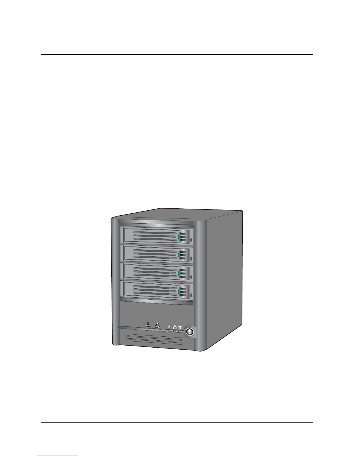
Intel® Entry Storage System SS4000-E Feature Summary
1. Feature Summary
This Technical Product Specification provides detailed information about the hardware
components of the Intel
Storage System User Guide for complete feature, configuration and operation details of the
®
Intel
Entry Storage System SS4000-E Network Attached Storage (NAS) Management Software
®
Entry Storage System SS4000-E. Please refer to the Intel® Entry
that is shipped with each storage system.
The Intel
board, with a single Intel
one Intel
256MB of DDR SDRAM memory and a single 200 W power supply. Intel
®
Entry Storage System SS4000-E includes a chassis, Intel® XScale® Processor based
®
31244 SATA Controller, dual Intel® 82541 Gigabit Ethernet Network controllers,
®
XScale® 80219 processor, four Serial ATA hard disk drive carriers,
®
-based system boards
and chassis have feature sets designed to support the high-density storage market.
The Intel
chassis is a printed circuit board with features that were designed to support the storage system
market. The architecture is based on the Intel
For more information on the Intel® Entry Storage System SS4000-E Storage Management Software, please refer to the
Intel® Storage Management User Guide available from Intel Business Link (IBL), support.intel.com or your Intel sales
representative.
®
XScale® Processor based board that is installed in the Storage System SS4000-E
®
XScale® Processor family.
1
2
3
4
1
2
TP000086
Figure 1. Intel® Entry Storage System SS4000-E
Revision 1.2 1
Page 8
Feature Summary Intel® Entry Storage System SS4000-E
Intel® Entry Storage System SS4000-E Hardware Feature Summary
Storage Capacity
Drive Bays
Hard Disk Drive Supported
Processor
Memory Capacity
Memory Type
DIMM Slots
SATA Compliance
Client Connectivity
Front Panel
LEDs
Power
Back Panel
Buttons and Switches
I/O Connectors
Power Receptacle
Chassis
Form Factor
Height
Width
Depth
Expandable to 1.0 TB – using four 250 GB drives
Expandable to 2.0 TB – using four 500 GB drives
NOTE: For specific drive family and capacities supported,
please refer to the SS4000-E Tested Hardware and OS List
(THOL)
4 Serial ATA (SATA) Hot Pluggable
3.5 inch SATA
NOTE: For specific drive family and capacities supported,
please refer to the SS4000-E Tested Hardware and OS List
(THOL)
A single Low Voltage Intel® XScale® 80219 processor
operating @ 400 MHz
NOTE: The system board is designed to support multiple
XScale processors but it is not designed such that the
processor can be replaced.
1 GB maximum, using 64-bit DDR SDRAM
512 MB maximum, using 32-bit DDR SDRAM
System ships with 256MB memory
IMPORTANT: Intel® Entry Storage System SS4000-E uses
an 80219 processor which supports a maximum of 1GB of
64 bit DDR SDRAM system memory and 512MB of 32 bit
DDR SDRAM. The system ships with 256MB memory
installed and as configured will support a maximum of 512
MB memory.
NOTE: Only qualified service personnel should service system
memory.
Synchronous Dynamic Random Access Memory (SDRAM),
PC200 – system ships with 256 MB memory
NOTE: For specific memory recommendations please refer to
the Tested Hardware and OS List (THOL). Only qualified
service personnel should service system memory.
One 184-pin DIMM socket
SATA 1.5Gb/s
Client Connectivity via Dual Gigabit Ethernet
Network Ports, Disk Activity / Fault, System Status, Power,
Global Disk Activity
Power button
Reset button
2x RJ-45 Ethernet ports, 2 USB 2.0 Ports
1x IEC AC per installed power supply module
Cube chassis
214mm (8.42”)
160mm (6.30”)
243mm (9.6”)
2
Revision 1.2
Page 9
Intel® Entry Storage System SS4000-E Feature Summary
Weight
Color
System Cooling
Fans
Power
Configuration
Max AC input current (PS Enclosure)
Max +3.3 V output
(PS Enclosure)
Max +5 V output
(PS Enclosure)
Max +12 V output current
(PS Enclosure)
Max -5 V output current
(PS Enclosure)
Max -12 V output current
(PS Enclosure)
Max +5V Standby output current
(PS Enclosure)
Environment
Ambient Temperature
Relative Humidity
Acoustics
Electrostatic Discharge
System Cooling Requirement in
British Thermal Units (BTU) per Hour
Safety Compliance
Argentina
Canada
China
Europe, CE Mark
Germany
International
As shipped (zero drives): approximately 3.18 kg, 7 pounds
Fully configured (four drives): approximately 5.45 kg, 12
pounds
Shipping container: 7.75 kg, 17 pounds (includes overpack
and accessories – with drives)
Height 311mm (12.25”)
Width 286mm (11.25”)
Length 489mm (19.25”)
Black
Chassis includes one single rotor 92 mm system fan for
cooling the hard drives, baseboard and SATA backplane.
The power supply enclosure contains one 40mm fan.
200 W continuous power supply. Intel Entry Storage System
SS4000-E ships with one 200W power supply
4 Amperes at 115 Vrms, 2 Amperes at 230 Vrms
17.0 A
(total combined power for the+3.3 V and +5 V outputs should
not exceed 65 W).
12.0 A
(total combined power for the+3.3 V and +5 V outputs should
not exceed 65 W).
10.0 A
0.3A
0.5 A
1.5 A
Operating (system): 10 degrees Celsius to +35 degrees
Celsius, with maximum change not to exceed 10 degrees
Celsius per hour; non-operating (system): -40 degrees
Celsius to +70 degrees Celsius.
Non-operating: 90%, non-condensing @ 35 degrees Celsius
non-condensing
4.7 BA in an idle state in at typical office ambient
±15 Kilovolt (KV) per Intel® Environmental test specification
< 680 BTU/hour
IRAM
UL60950 – CSA (60950 (UL and cUL)
GB4943- CNCA Certification
EN60950 (complies with73/23/EEC)
GS License
IEC60950 (CB Report and Certificate)
Revision 1.2 3
Page 10
Feature Summary Intel® Entry Storage System SS4000-E
Nordic Countries
Russia
United States
Electromagnetic Capability (Class B)
(EMC)
Australia/New Zealand
Canada
China
Europe, CE Mark
International
Japan
Korea
Russia
Taiwan
United States
EMKO-TSE (74-SEC) 207/94
GOST 50377-92
UL– 60950 – CSA 60950 (UL and cUL)
AS/NZS 3548 (based on CISPR 22)
ICES-003
GB 9254 - CNCA Certification
GB 17625 - (Harmonics) CNCA Certification
EN55022; EN55024 & EN61000-3-2;-3-3 (complies with
89/336/EEC)
CISPR 22
VCCI
RRL MIC 1997-41 & 1997-42
GOST 29216-91 & 50628-95
CNS13438
FCC, Part 15
4
Revision 1.2
Page 11
Intel® Entry Storage System SS4000-E Feature Summary
1.1 System Components
A block diagram of the storage system functional components is shown below.
Figure 2. Intel
®
Entry Storage System SS4000-E Block Diagram
The components included with this storage system are diagrammed below.
Revision 1.2 5
Page 12
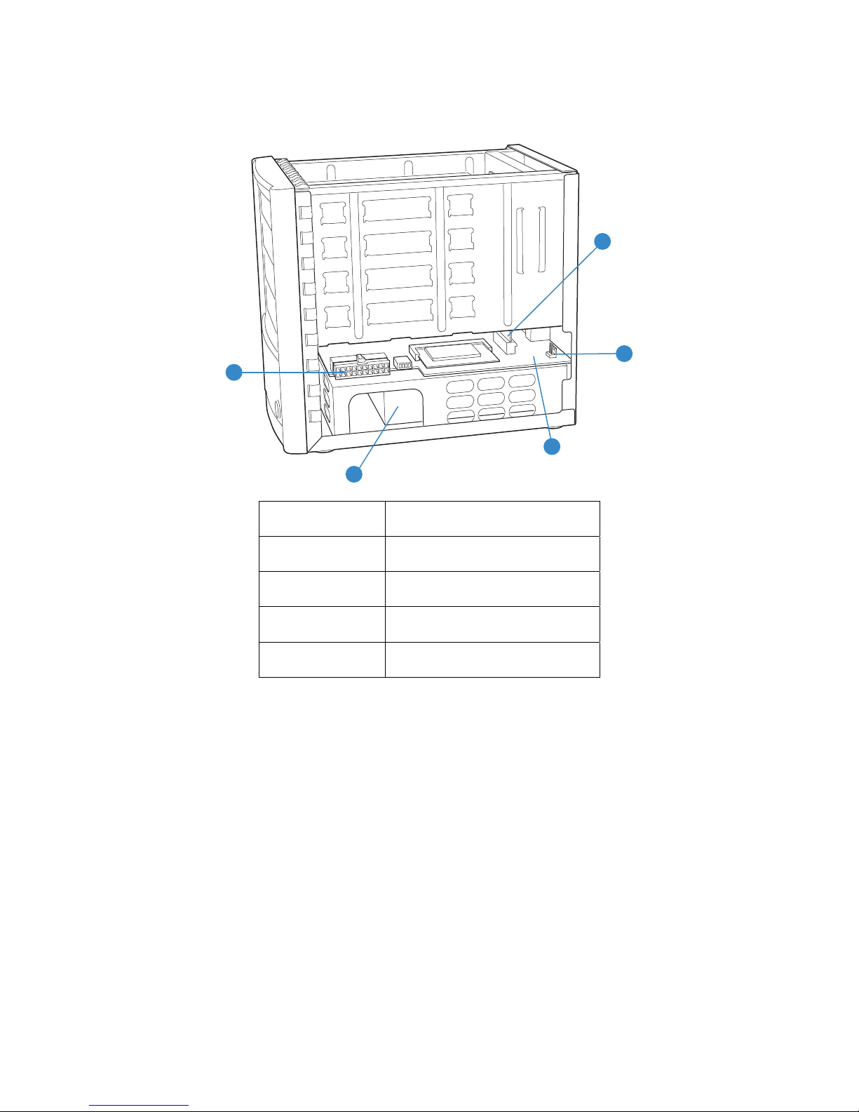
Feature Summary Intel® Entry Storage System SS4000-E
C
D
A
E
B
TP000228
A Power Supply Connector
B Power Supply
C SATA Backplane Connector
D Fan Connector
E System Board
Figure 3. System Components - Right Side
6
Revision 1.2
Page 13
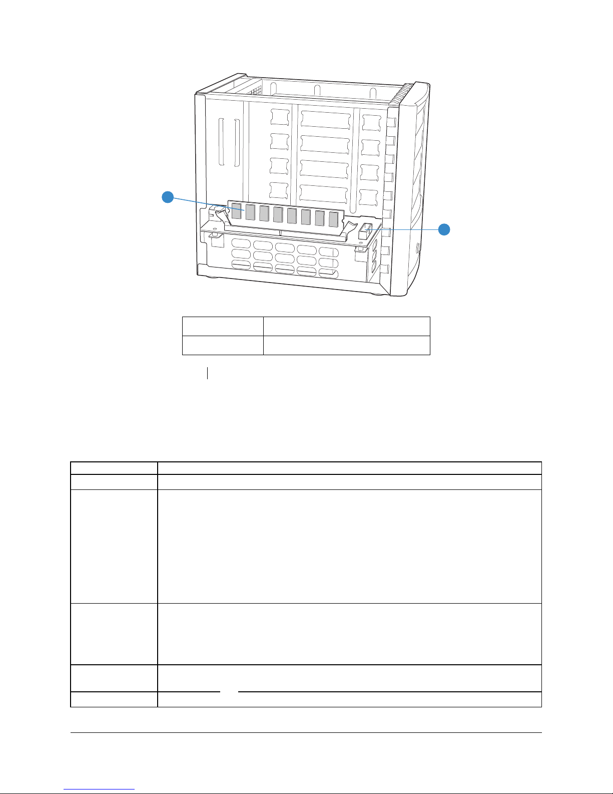
Intel® Entry Storage System SS4000-E Feature Summary
A
B
TP000229
A System Memory
B Front Panel Cable Connector
Figure 4. System Components – Left Side
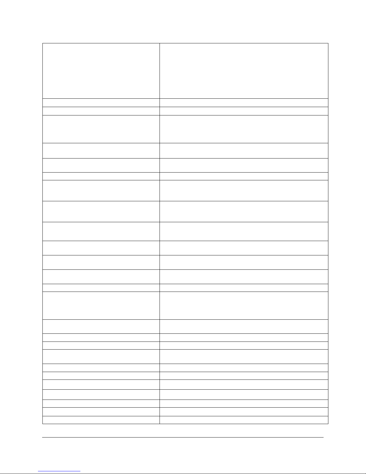
1.2 System Board Feature Set
The Intel® Entry Storage System SS4000-E Board provides the following feature set, as
implemented in the Intel
Feature Description
Processor Single IOP80219 544 LPBGA (35mm) package with 200 MHz internal bus speed.
Memory
Peripheral
Interfaces
LAN Intel® 82541 Dual 10/100/1000 Megabits per second (Mb/s) Ethernet Local Area
Fans Support for one system fan
Revision 1.2 7
®
Entry Storage System SS4000-E:
IMPORTANT: Intel® Entry Storage System SS4000-E uses an 80219
processor which supports a maximum of 1GB of 64 bit DDR SDRAM system
memory and 512MB of 32 bit DDR SDRAM. The system ships with 256MB
memory installed and as configured will support a maximum of 512 MB
memory.
NOTE: For specific memory recommendations please refer to the Tested
Hardware and OS List (THOL).
NOTE: The Intel Entry Storage System SS4000-E ships with 256MB memory. Only
qualified service personnel should service system memory.
1 32-bit PCI bus operating at 33MHz providing connection for:
• 2 10/100/1000 Megabits per second (Mb/s) Ethernet LAN ports
• 2 USB 2.0 ports
• 1 Serial ATA 4 port controller operating at 1.5Gigabits per second
Network (LAN) Controller.
Page 14
Feature Summary Intel® Entry Storage System SS4000-E
1.3 Serial ATA (SATA) Host Bus Adapter
The Intel® Entry Storage System SS4000-E ships with one 4 port PCI-X to SATA Host Bus
Adapters. The SATA HBA provides the following feature set:
Feature Description
Number of ports 4, using a single Intel 31244 SATA controller.
Serial ATA Bus Speed 1.5 Gb/s
Serial ATA Data Transfer rate 150 MB/s
PCI Bus width and speed 64-bit/133 MHz PCI-X bus, backward compatible to 32-bit/33 MHz and
64-bit/66 MHz (implemented in backward compatible mode)
PCI Data transfer rate Maximum 1.06 GB/s (backward compatible mode operates at 32-bit/33
MHz yielding maximum of 132 MB/s)
Hot Swap Yes
RAID Management Tools Yes, via Intel® Storage Management Software using the user interface
Please refer to http://www.intel.com/design/storage/serialata/docs/gd31244.htm
for more information.
1.4 SATA Hot Swap Backplane
The SATA Hot Swap backplane board provides the following feature set:
Feature Description
Supports up to 4
drives.
Drive Status LEDs Support for separate drive status LEDs that are visible at the front of each drive
Slots provided for docking up to four 1.5 Gigabits per second (Gb/s) Serial ATA
hot swap hard drives
carrier. These LED’s indicate the following:
• Green LED –
o ON, Drive available
o Blink, Drive activity
o Off during a fault condition
• Amber LED –
o ON, Drive fault
o Blink, Drive is rebuilding
o Off during normal operation
8
Revision 1.2
Page 15

Intel® Entry Storage System SS4000-E Feature Summary
1.5 Enclosure Management
The enclosure management controller monitors various aspects of the storage enclosure. The
enclosure management controller is comprised of the following elements and supports
associated features:
• CPLD (Lattice ispMACH 4064V)
• Hardware Monitoring I/C (Winbond W83792AD)
o Thermal sensing
o Voltage level sensing
o CPU temperature sensing
1.5.1 Fan Control
Fan control is managed through the Winbond W83792AD hardware monitoring component. In
the event of a fan failure the system will shutdown to prevent an over temperature situation.
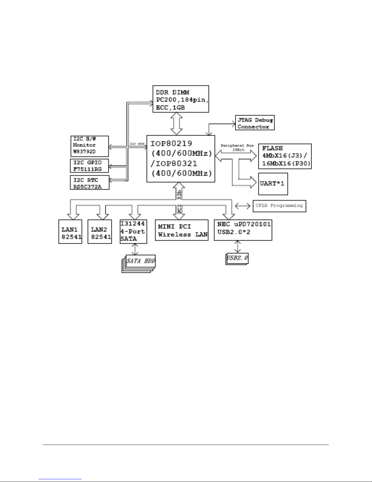
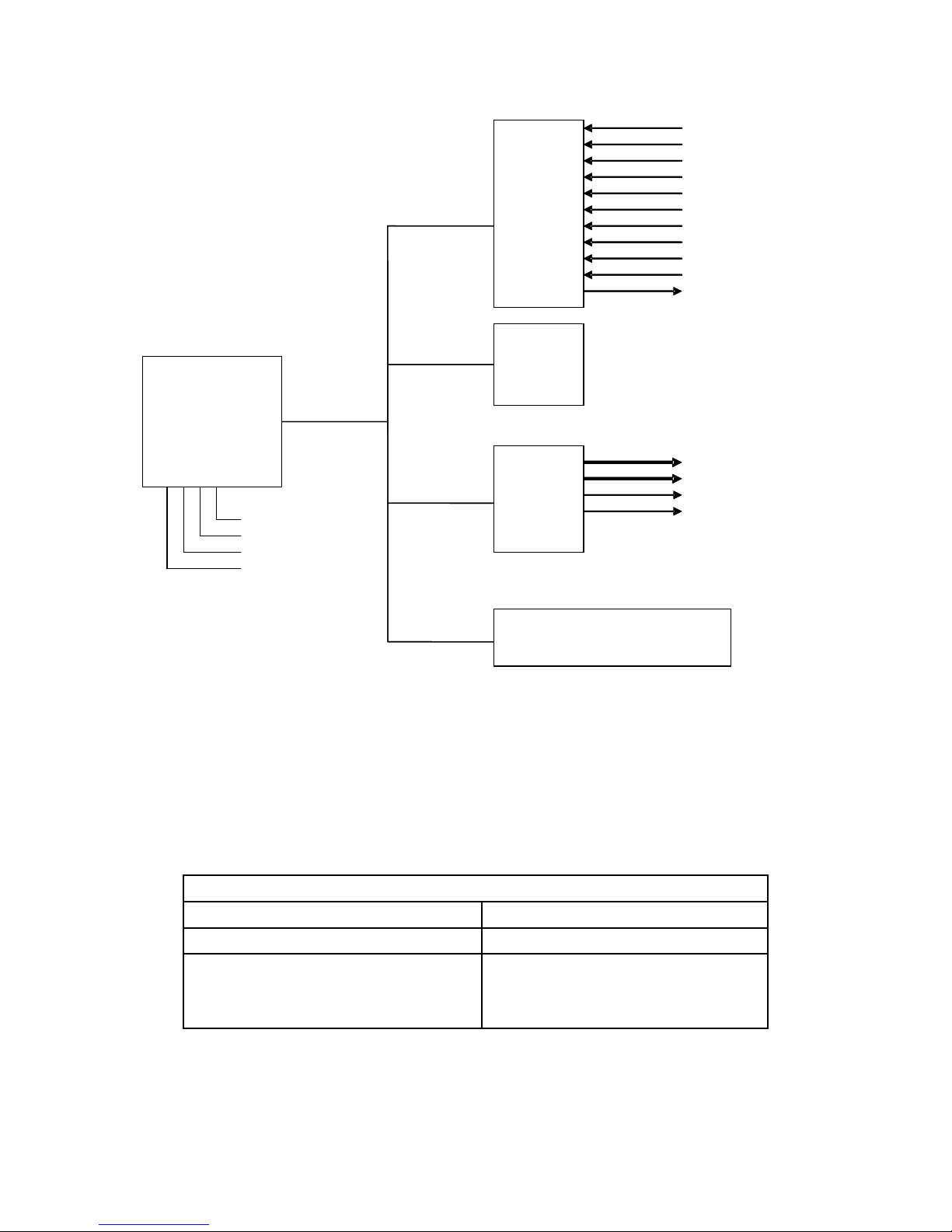
1.5.2 I2C Serial Bus Interface
The enclosure management controller supports one independent I2C interface port with bus
speed of up to 400 Kb/s. Additional I2C connections and addressing are shown in the following
block diagram.
Revision 1.2 9
Page 16
Feature Summary Intel® Entry Storage System SS4000-E
r
r
r
r
r
r
12V
12V
5V
5V
3.3V
3.3V
2.5V
2.5V
1.3V
1.3V
5VSB
5VSB
3.3VSB
3.3VSB
- 5V
- 5V
- 12V
- 12V
TAC
TAC
PWM
PWM
0x5A
H
HW
Monito
Monito
W83792AD
W83792AD
IO
IO
GPI ’ s
GPI ’ s
Shutdown
Shutdown
Reset
Reset
Sys - Ambe
Sys - Ambe
Disk - Green -
Disk - LED
Green
- LED
0x64
0x6E
0xA0
RT
RT
RS5C372A
RS5C372A
GPI
GPIO
75111RG
75111RG
DIM
DIM
HDD LINK
HDD LINK
HDD Fault/Rebuild
HDD Fault/Rebuild
Sys - Green
Sys - Green -LED
Disk - Ambe
Disk - Ambe
LED
-
Figure 5. I2C Serial Bus Interface Block Diagram
1.5.3 Hard Disk Drive LEDs
The Intel® Entry Storage System SS4000-E SATA HSBP contains one LED for each of the four
drive slots.
Drive Status LED
Drive Available Solid Green
Drive Activity Blinking Green
Drive is Rebuilding Blinking Amber
Fault Condition Solid Amber
10
Table 1. HDD LED Function
Activity Light States
Revision 1.2
Page 17
Intel® Entry Storage System SS4000-E Feature Summary
1.6 Chassis Dimensions and Weight
Table 2. Chassis Dimensions and Weight
Height
Width
Depth
Weight
Chassis - as shipped (0 drives)
Chassis - fully configured (4 drives)
Shipping container
Shipping Container Dimensions
214mm
160mm
243mm
3.5 kilograms
5.45 kilograms
1.7 kilograms
Height
Length
Width
8.42 inches
6.30 inches
9.6 inches
7 pounds
12 pounds
3.8 pounds
311mm (12.25”)
489mm (19.25”)
286mm (11.25”)
Revision 1.2 11
Page 18

Feature Summary Intel® Entry Storage System SS4000-E
1.7 Back Panel I/O Ports and Features
At the rear of the chassis are two 10/100/1000 Network Interface Card (NIC) connectors and
two USB 2.0 ports. The Input/Output (I/O) connectors are integrated to the back panel. The
figure below shows the rear of the storage system.
Figure 6. Chassis Rear
12
Revision 1.2
Page 19

Intel® Entry Storage System SS4000-E Feature Summary
1.8 Front Panel and Hard Disk Drive Bays
1
2
3
4
1
2
Figure 7. Hard Disk Drive Bays
1
2
3
4
1
2
AF000227
Revision 1.2 13
Figure 8. Chassis Front
AF000310
Page 20

Feature Summary Intel® Entry Storage System SS4000-E
1.8.1 Front/Rear Panel Controls and Indicators
The front/rear panel controls and indicators are defined below:
Table 3. Front and Rear Control Button Functions
Power button (front)
Reset button (rear)
Toggles the system power on/off.
Holding button down will shut the system down.
Reboots the system and resets the Ethernet ports to default values (DHCP
client) and the Administrator password to default values.
Table 4. Front Panel LED Indicators
Power
System Status
NIC1 Link
NIC1 Activity Blinking green indicates Ethernet activity.
NIC2 Link
NIC2 Activity Blinking green indicates Ethernet activity.
Global Disk Activity
Continuous green light indicates the system has power applied to it.
No light indicates the system does not have power applied to it.
Continuous green indicates system is running and operating normally.
Green blinking light indicates system is in process of booting up or shutting down.
Continuous amber light indicates fault present – a critical or non-recoverable
condition.
Continuous green indicates an active Ethernet connection.
Off indicates no active Ethernet connection.
Continuous green indicates an active Ethernet connection.
Off indicates no active Ethernet connection.
Continuous green light indicates drive health is good (1-4 drives).
Amber blinking light indicates one or more drives are rebuilding.
14
Revision 1.2
Page 21

Intel® Entry Storage System SS4000-E Feature Summary
A NIC1 Activity
B NIC1 Ethernet Link
C NIC2 Ethernet Link
D NIC2 Activity
E Global Disk Status
F System Status
G Power Status
H Power Button
Figure 9. Front Panel
Revision 1.2 15
Page 22

Feature Summary Intel® Entry Storage System SS4000-E
A
D
21
E
B
K
C
F
G
H
AF000084
A System Fan
B USB Ports
C Power Connector
D NIC2 Ethernet Port
E NIC1 Ethernet Port
F Reset Button
G Power Supply Fan
H Cable Lock
Figure 10. Rear Panel
16
Revision 1.2
Page 23

Intel® Entry Storage System SS4000-E Feature Summary
Table 5. Intel Disk Drive Carrier LED Functions
Continuous green indicates the drive is available.
Blinking green indicates drive activity
Disk Drive Activity LED
Light Pipe
Continuous amber indicates a fault condition possibly requiring the drive to
be replaced.
Blinking amber indicates the drive is currently rebuilding RAID.
A
AF000305
A LED Light Pipe
Figure 11 Hard Disk Drive Carrier LED Light Pipe
Revision 1.2 17
Page 24

Power Sub-System Intel® Entry Storage Sy stem SS4000-E
2. Power Sub-System
This section provides an overview of the Intel® Entry Storage System SS4000-E power supply.
The power supply is an auto sensing power supply and will detect the input voltage and provide
the appropriate output voltage.
Watt power supply.
NOTE: The Intel
2.1 Power Supply
The Intel® Entry Storage System SS4000-E accommodates one 200 Watt (W) power supply.
PARAMETER MIN Nominal MAX
Voltage (in) 90 VAC
Voltage (in frequency) 47 Hz 63 Hz
Input Current 4 (115V)
The power supply is designed to minimize EMI.
®
Entry Storage System SS4000-E ships with one 200
115-230 VAC
rms
253 VAC
rms
rms
2 (230V)
18
Revision 1.2
Page 25

Intel® Entry Storage System SS4000-E Power Sub-System
Figure 12. Power Supply Enclosure
2.1.1 Power Supply Outputs
The Intel® Entry Storage System SS4000-E power system supports one 200 W Power Supply.
The power supply provides six DC output rails; +3.3V, +5V, +12V, -5V, -12V and +5Vsb.
Table 5. Power Supply Output Summary (200W 10 second peak ratings)
+3.3V +5V +12V -5V -12V 5Vsb
17A 12A 10A 0.3A 0.5A 1.5A
NOTE: The total combined power for +3.3V and +5V should not exceed 65W. The maximum continuous average DC
output power shall not exceed 200W. The peak +12VDC output power shall not exceed 13 seconds in duration.
The power supply requires a #1 and/or #2 Phillips screwdriver to remove the chassis cover for
insertion and extraction of the power supply.
Revision 1.2 19
Page 26

Power Sub-System Intel® Entry Storage System SS4000-E
2.1.1.1 Front Panel Power Supply LED Indicator
The power supply is connected to a single external LED to indicate the status of the power
supply. When AC is applied to the Power Supply Unit (PSU) and the system is powered on, the
LED will be solid on green to indicate that all the power outputs are available. Refer to the
following table for conditions of the LED.
Table 6. Front Panel Power Supply LED Indicator
Front Panel Power Supply LED
Off indicates no power supplied to the unit.
Continuous green indicates power is supplied to the unit.
20
Revision 1.2
Page 27

Intel® Entry Storage System SS4000-E Power Sub-System
2.2 Output Power/Currents
The following table defines power and current ratings for this 200 Watt continuous (300 Watts
peak) power supply. The output power shall not exceed the rated output power. The power
supply must meet both static and dynamic voltage regulation requirements for the minimum
loading conditions. Outputs are not required to be peak loaded simultaneously.
Table 7. Load Ratings
Voltage Rail Minimum Maximum Peak
+3.3V 0.3A 17.0A
+5V 1.0A 12.0A
+12V 0.5A 10.0A 13.0A
-5V 0.0A 0.3A
-12V 0.0A 0.5A
+5Vsb 0.0A 1.5A 2.0A
NOTE: The total combined power for +3.3V & +5V should not exceed 120W. The total combined power for +12V, 12V, 5Vsb should not exceed 300W.
2.3 Voltage Regulation
The power supply output voltages must stay within the following voltage limits when operating at
steady state and dynamic loading conditions. All outputs are measured with reference to the
COM/GND (black wire)
Table 8. Voltage Regulation Limits
Parameter Min Nom Max Units Tolerance
+3.3V +3.14 +3.30 +3.47 V
+5V +4.75 +5.00 +5.25 V
+12V +11.4 +12.00 +12.6 V
-5V -4.5 -5.0 -5.5 V
-12V -10.8 -12.0 -13.28 V
+5Vsb +4.75 +5.0 +5.25 V
+/-5%
rms
+/-5%
rms
+/-5%
rms
+/-10%
rms
+/-10%
rms
+/-5%
rms
2.4 Protection Circuits
Protection circuits inside the power supply shall cause only the power supply’s main outputs to
shutdown. If the power supply latches off due to a protection circuit tripping, an AC cycle OFF
shall be able to reset the power supply.
2.4.1 AC Inrush Current Regulation
The power supply shall have current limit to prevent outputs from exceeding threshold values. If
the current limits are exceeded the power supply shall shutdown. This will be cleared by an AC
power interruption. The power supply shall not be damaged from repeated power cycling in this
condition. The 5Vsb shall be protected under over-current or shorted conditions so that no
damage can occur to the power supply.
Revision 1.2 21
Page 28

Power Sub-System Intel® Entry Storage System SS4000-E
Voltage Over Current Limit
115Vrms 50A
230Vrms 100A (@ 25°C ambient cold start)
22
Revision 1.2
Page 29

Intel® Entry Storage System SS4000-E Power Sub-System
2.4.2 Over Voltage Protection (OVP)
The power supply over voltage protection shall be locally sensed. In an over voltage fault
occurs, the supply will latch all DC outputs into a shutdown state except 5Vsb output. This latch
shall be cleared by an AC power interruption. Table 13 contains the over voltage limits. The
values are measured at the output of the power supply’s connectors. The voltage shall never
exceed the maximum levels when measured at the power pins of the power supply connector
during any single point of failure. The voltage shall never trip any lower than the minimum
levels when measured at the power pins of the power supply connector.
Table 9. Over Voltage Protection (OVP) Limits
Output Voltage Min (V) Max (V)
+5V 5.5 7.0
+3.3V 3.5 4.5
+12V 13.0 16.8
2.4.3 Short Circuit Protection (SCP)
The power supply shall shutdown and latch off for shorting +3.3V, +5V, -5V, +12V or -12V rails.
The main output short circuit of any impedance shall be less than 0.1 ohms. The maximum
short circuit current in any output shall not exceed 240VA.
Revision 1.2 23
Page 30

System Cooling Fan Intel® Entry Storage System SS4000-E
3. System Cooling Fan
The Intel® Entry Storage System SS4000-E includes a cooling fan that has a single rotor 92 mm
fan, mounted on the rear of the chassis. The Power Supply enclosure contains one 40 mm fan
for cooling the power supply module.
3.1 Fan Control
The fan provides optimal acoustic and thermal performance. The fan is capable of running at
two speeds, low for most office environments, and high for higher temperature environments.
This is controlled by two backplane mounted temperature sensors. If a sensor on the
backplane is equal to or higher than 42 °C, the fan will set to high speed. The temperature
reading at the backplane depends on hard disk power and loading, but will occur at the high end
of the operating temperature range, somewhere around 32 °C to 35 °C. If a sensor is between
37 °C and 42 °C, the fan speed will not change. If a sensor drops below 37 °C, the fan will be
set back to low speed.
If a sensor on the backplane is between 50 °C and 55 °C, a warning event is recorded in the
system log and an email alert is sent. If a sensor on the backplane is equal to, or exceeds, 55
°C a critical error will be recorded in the system log and the system will initiate a shutdown.
When the system is powered back on, the system log will show the appropriate thermal events.
If the CPU temperature is between 80 °C and 85 °C the system will log a warning event and can
send an email alert. If the CPU temperature reaches, or exceeds, 85 °C the system will log a
critical event and initiate a shutdown. When the system is powered back on, the system log will
show the thermal shutdown event.
The fan speed is monitored for proper operation and events are logged in the system log based
on the fan rpm. If the fan speed is greater than 1450 rpm the fan operating normally. If the fan
speed is greater than or equal to 1323 rpm but less than 1450 rpm a warning event will be
recorded in the system log. If the fan speed is less than 1323 a critical event is recorded in the
system log and an email alert will be sent. This is repeated daily until the problem is resolved or
the system initiates a shutdown due to an ‘overtemp’ condition.
Fan
Speed
Low ~ 6.15V ~1800
High ~9.75V ~2600
Fan Voltage RPM
24
Revision 1.2
Page 31

Intel® Entry Storage System SS4000-E System Cooling Fan
A
C
B
D
AF000303
A System Chassis Fan
B System Board
C Backplane and connectors
D Hard Disk Drive
Figure 13. Chassis Fan and Backplane Location
Revision 1.2 25
Page 32

Chassis Bays Intel® Entry Storage System SS4000-E
4. Chassis Bays
The Intel® Entry Storage System SS4000-E chassis provides four hard drive bays at the front of
the chassis. All hard drive bays may be populated with a carrier-mounted 3.5 inch SATA hard
disk drive. The latch must be open prior to inserting the drive carrier containing a disk drive.
Once inserted the latch can be pushed closed to ensure the disk drive is properly connected to
the backplane connector. NOTE: For specific drive family and capacities supported,
please refer to the SS4000-E Tested Hardware and OS List (THOL)
1
2
3
1
2
AF000233
1
2
3
4
1
2
26
TP000230
Revision 1.2
Page 33

Intel® Entry Storage System SS4000-E Chassis Bays
2
3
4
1
2
TP02349
Figure 14. Disk Drive Carrier Insertion and Removal
Revision 1.2 27
Page 34

Chassis Bays Intel® Entry Storage System SS4000-E
4.1 Hard Disk Drive Bays
The Intel® Entry Storage System SS4000-E chassis can support up to four carrier-mounted
SATA, 3.5 inch x 1 inch, hard disk drives. The SATA drives may be “electrically” hot-swapped
while the system power is applied, i.e., after POST (Power On Self Test). See the Intel
Storage System SS4000-E User Guide for more information.
NOTE:
1) All drives must be populated in order, from top to bottom, in drive bay 1 thru drive bay 4. For
example, if only 2 drives are installed, 2 drives should be inserted into bays 1 thru 2, and the
remaining two drive bays left empty. When the additional two drive bays are populated they
should be filled in order, i.e., bay 3 followed by bay 4.
1
1
2
2
®
Entry
3
3
4
4
1
2
TP02348
Figure 15. Drive Ordering
2) Once a particular RAID configuration is applied to the present drives, if the drives are removed
from the system for any reason, they will need to be re-installed in the exact same drive bays
they were removed from. Please use the HDD labels provided in your
SS4000-E
shipping container to number the drives 1 thru 4 prior to removal.
Intel® Entry Storage System
3) If a failed drive needs replacing, it should be replaced with the exact same manufacturer, model,
and size.
4)
For more information on configuring supported RAID levels, refer to the Intel® Storage
System SS4000-E User Guide available from Intel Business Link (iBL), support.intel.com, or your
Intel sales representative.
28
Revision 1.2
Page 35

Intel® Entry Storage System SS4000-E Chassis Bays
1
2
3
4
1
2
AF000227
Figure 16. Hard Disk Drive Bays
4.1.1 Hard Disk Drive Carrier
Each hard drive used in the system must be mounted to a drive carrier, making insertion and
extraction of the drive from the chassis very simple. Each drive tray has its own dual purpose
latching mechanism that is used to both insert/extract drives from the chassis and lock the
carrier in place. To remove the drive, depress the latch to remove the drive. Each drive carrier
also supports a light pipe providing a drive status indicator, located on the backplane, to be
viewable from the front of the chassis. See Figure 7 for location of LED light pipe on the drive
carrier.
AF000226
Revision 1.2 29
Page 36

Chassis Bays Intel® Entry Storage System SS4000-E
Figure 17. Hard Drive Carrier Assembly
30
Revision 1.2
Page 37

Intel® Entry Storage System SS4000-E System Interconnection
5. System Interconnection
5.1 Chassis Internal Connectors
There are four Serial ATA (SATA) connectors on the backplane that the hard drives connect to.
The backplane is connected to the motherboard via a PCI-Express connector that is used only
as a connector for the particular signals used.
• The backplane supports the four expansion drives and provides the interconnect
between the backplane and the SATA controller on the motherboard.
5.2 I/O Panel Connectors
The Intel® Entry Storage System SS4000-E provides an aperture for the rear I/O ports. The
following are the I/O ports available:
• Two RJ-45 LAN connectors
• Two USB 2.0 ports
Revision 1.2 31
A USB Ports
B Ethernet Ports
Figure 18. Chassis Rear I/O Connectors
Page 38

System Interconnection Intel® Entry Storage System SS4000-E
5.3 SATA HSBP Connectors
5.3.1 SATA Connector
The following table defines the pin-outs of the SATA Drive Connector. The first connector
carries signals from drive 1, the second connector is connected to drive 2, the third connector
connects to drive 3 and the fourth connector connects to drive 4.
Table 10. SATA Connector Pin-out
Pin Signal Name Pin Signal Name
1 GND 17 GND
2 TX+ 18 GND
3 TX- 19 GND
4 GND 20 +5V
5 RX- 21 +5V
6 RX+ 22 +5V
7 GND 23 GND
8 +3.3V 24 GND
9 +3.3V 25 GND
10 +3.3V 26 +12V
11 GND 27 +12V
1 71 21
2 6 222
Figure 19. SATA Backplane Connector
32
Revision 1.2
Page 39

Intel® Entry Storage System SS4000-E System Interconnection
5.3.2 Power Connector
The following table defines the pin-out of the 2x10 Power Connector.
Table 11. Power Connector Pin-out
Pin Signal Name Pin Signal Name
1 +3.3V 11 +3.3V
2 +3.3V 12 -12V
3 GND 13 GND
4 +5V 14 PS-ON
5 GND 15 GND
6 +5V 16 GND
7 GND 17 GND
8 Power Good 18 -5V
9 Stand-By 5V 19 +5V
10 +12V 20 +5V
20
10
11
1
PSA1
Revision 1.2 33
Page 40

System Interconnection Intel® Entry Storage System SS4000-E
5.3.3 Front Panel Connector
The following table defines the pin-outs of the 2x8 Front Panel connector.
Table 12. Front Panel Power Connector
Pin Signal Name Pin Signal Name
1 Power LED+ 2 Power LED3 VCC3R 4 GND
5 RAIDA 6 Status LED
7 RAIDC 8 RAIDB
9 LAN1-ACT 10 LAN1-LINK
11 LAN1-1G 12 LAN1-100M
13 LAN2-ACT 14 LAN2-LINK
15 LAN2-1G 16 LAN2-100M
34
Revision 1.2
Page 41

Intel® Entry Storage System SS4000-E Regulatory Information
6. Regulatory Information
6.1 Product Regulation Requirements
Intended Application – This product was evaluated as Information Technology
Equipment (ITE), which may be installed in homes, offices, schools, computer rooms,
and similar commercial type locations. The suitability of this product for other product
categories and environments (such as: medical, industrial, telecommunications, NEBS,
residential, alarm systems, test equipment, etc.), other than an ITE application, may
require further evaluation.
6.1.1 Product Safety Compliance
UL60950 – CSA 60950(USA / Canada)
EN60950 (Europe)
IEC60950 (International)
CB Certificate & Report, IEC60950 (report to include all country national deviations)
GS License (Germany)
GOST R 50377-92 - License (Russia)
Belarus License (Belarus)
Ukraine License (Ukraine)
CE - Low Voltage Directive 73/23/EEE (Europe)
IRAM Certification (Argentina)
6.1.2
Product EMC Compliance – Class B Compliance
FCC /ICES-003 - Emissions (USA/Canada)
CISPR 22 – Emissions (International)
EN55022 - Emissions (Europe)
EN55024 - Immunity (Europe)
EN61000-3-2 - Harmonics (Europe)
EN61000-3-3 - Voltage Flicker (Europe)
CE – EMC Directive 89/336/EEC (Europe)
VCCI Emissions (Japan)
AS/NZS 3548 Emissions (Australia / New Zealand)
BSMI CNS13438 Emissions (Taiwan)
GOST R 29216-91 Emissions (Russia)
GOST R 50628-95 Immunity (Russia)
Belarus License (Belarus)
Ukraine License (Ukraine)
RRL MIC Notice No. 1997-41 (EMC) & 1997-42 (EMI) (Korea)
Revision 1.2 35
Page 42

Regulatory Information Intel® Entry Storage System SS4000-E
6.1.3 Certifications / Registrations / Declarations
UL Certification (US/Canada)
CE Declaration of Conformity (CENELEC Europe)
FCC/ICES-003 (USA/Canada)
VCCI Certification (Japan)
C-Tick Declaration of Conformity (Australia)
MED Declaration of Conformity (New Zealand)
BSMI Certification (Taiwan)
GOST R Certification / License (Russia)
Belarus Certification / License (Belarus)
RRL Certification (Korea)
IRAM Certification (Argentina)
Ecology Declaration (International)
36
Revision 1.2
Page 43

Intel® Entry Storage System SS4000-E Regulatory Information
6.2 Product Regulatory Compliance Markings
The Intel Server Chassis product bears the following regulatory marks.
Regulatory Compliance Country Marking
cULus Listing Marks USA/Canada
GS Mark Germany
CE Mark Europe
FCC Marking (Class A) USA
EMC Marking (Class A) Canada
CANADA ICES-003 CLASS B
CANADA NMB-003 CLASSE B
C-Tick Mark Australia / New
Zealand
VCCI Marking (Class A) Japan
BSMI Certification
Number & Class A
Warning
GOST R Marking Russia
RRL MIC Mark Korea
Taiwan
6.2.1 Component Regulation Requirement Need to Support System Level Certifications
Component Power Supplies must have the following certifications:
UL, cUL
CNCA China Certification
Ctick DOC
BSMI RPC
CE DOC
CB Report (including all national deviations).
Revision 1.2 37
Page 44

Regulatory Information Intel® Entry Storage System SS4000-E
All peripheral devices, such as CD ROMS, Disk drives, Tape drives shall have the following
certifications: UL or CSA NRTL, CSA or cUL, and TUV or VDE and SEMKO or NEMKO or
DEMKO or FIMKO, CE, and FCC.
All Fans shall have the minimum certifications: UL and TUV or VDE
All current limiting devices shall have UL and TUV or VDE certifications and shall be suitable
rated for the application where the device in its application complies with IEC60950.
All lithium batteries shall be UL recognized and battery circuits are to have suitable reverse bias
current protection for the application it is used in.
All printed wiring boards shall be rated UL94V-0 and be sourced from a UL approved printed
wiring board manufacturer.
All connectors shall be UL recognized and have a UL flame rating of UL94V-0.
All wiring harnesses shall be sourced from a UL approved wiring harness manufacturer. SELV
Cable to be rated minimum 80 V.
All plastics used must be made of a UL recognized material, and have the appropriate flame
ratings mandated by IEC60950 per system level requirements. All plastics parts shall be
manufactured by an UL approved fabricator and the parts shall be marked with the appropriate
UL traceability markings. Markings to include:
Plastic Fabricators name and/or UL Fabricator ID
Material Name (for example GE, C2800)
Date Code
Product safety label must be printed on UL approved label stock and printer ribbon. Alternatively
labels can be purchased from a UL approved label manufacturer.
The product must be marked with the correct regulatory markings to support the certifications
that are specified.
Product documentation shall incorporate all safety required information to conform to certifiers
and regulators and the certifications issued for the product.
6.2.1.1 Product Ecology Requirements
All materials, parts and subassemblies must not contain restricted materials as defined in Intel’s
Environmental Product Content Specification of Suppliers and Outsourced Manufacturers –
http://supplier.intel.com/ehs/environmental.htm.
All plastic parts shall not use brominated flame retardant or any other halogenated retardants
that are not accepted by environmental programs such as Blue Angels, Nordic White Swan, and
Swedish TCO.
All plastic parts that weigh >25gm shall be marked with the ISO11469 requirements for
recycling. Example >PC/ABS< .
Packaging materials may not contain more than 100 ppm (total) of lead, cadmium, chromium or
mercury.
If sold as a retail product, packaging materials must be marked with applicable recycling logos
for Europe (green dot) and Japan (Eco-marks).
Product documentation shall incorporate all safety required information to conform to certifiers
and regulators and the certifications issued for the product.
All cords and cables shall contain < 100 ppm of cadmium.
European Restriction of Hazardous Substances (RoHS)
Intel has a system in place to restrict the use of banned substances in accordance with the
European Directive 2002/95/EC. Compliance is based on declaration that materials banned in
the RoHS Directive are either (1) below all applicable substance threshold limits or (2) an
approved/pending RoHS exemption applies.
38
Revision 1.2
Page 45

Intel® Entry Storage System SS4000-E Regulatory Information
Note: RoHS implementing details are not fully defined and may change.
Threshold limits and banned substances are noted below.
Quantity limit of 0.1% by mass (1000 PPM) for:
o Lead
o Mercury
o Hexavalent Chromium
o Polybrominated Biphenyls Diphenyl Ethers (PBDE)
Quantity limit of 0.01% by mass (100 PPM) for:
o Cadmium
Revision 1.2 39
Page 46

Environmental Limits Intel® Entry Storage System SS4000-E
7. Environmental Limits
7.1 System Office Environment
Table 13. Intel® Entry Storage System SS4000-E System Office Environment Summary
Parameter Limits
Operating Temperature 10 degrees celcius to +35 degrees celcius with the maximum rate of
change not to exceed 10 degrees celcius per hour.
Non-Operating Temperature -40 degrees celcius to +70 degrees celcius
Non-Operating Humidity 90%, non-condensing at 35 degrees celcius
Acoustic noise 4.7 BA in an idle state at typical office ambient temperature. (23 ±
degrees celcius)
Operating Shock No errors with a half sine wave shock of 2 Giga (1.024 x 10⁹) (G) (with
11 millisecond duration)
Package Shock Operational after a 30 inch free fall, although cosmetic damage may be
present (chassis weight 30 lbs)
Electrostatic Discharge (ESD) ±15 Kilovolt (KV) per Intel® Environmental test specification
System Cooling Requirement
in British Thermal Units (BTU)
per Hour
< 680 BTU/hour
7.2 System Environmental Testing
The system has been tested per the Intel® Environmental Standards Handbook, Intel document
number 662394-06. These tests include:
• Temperature Operating and Non-Operating
• Humidity Non-Operating
• Packaged and Unpackaged Shock
• Packaged and Unpackaged Vibration
• AC Voltage, Frequency and Source Interrupt
• AC Surge
• Acoustics
• ESD
• EMC Radiated Investigation
40
Revision 1.2
Page 47

Intel® Entry Storage System SS4000-E Environmental Limits
7.3 Environmental Limits
The following table summarizes environmental limits, both operating and non-operating.
Table 14. Intel® Entry Storage System SS4000-E Operating and Non-Operating Environmental
Limits
Temperature Specification
Non-operating -40 degrees celcius to 70 degrees celcius
Operating Temperature 10 degrees celcius to 35 degrees celcius
Thermal Map Must not exceed maximum Integrated Circuit (IC) junction temperature as specified
in the component data sheets (CPDs).
Thermal Shock Specification
Non-operating -40 degrees celcius to 70 degrees celcius
Humidity Specification
Non-operating 90% Relative Humidity (RH) at +35 degrees celcius
Vibration Specification
Non-Operating:
Shock Specification
Non-operating 25 G, 11 millisecond (msec)
ESD Specification
Operating Test (air) to 15 KV and (contact) to 2-8KV with limited errors.
EMI Specification
Operating Required to meet EMI emission requirements, tested as part of system.
2.2 Grms 5-500Hz for the unpackaged and 1.09 Grms 5-500Hz for the
packaged.
Revision 1.2 41
Page 48

Serviceability and Availability Intel® Entry Storage System SS4000-E
8. Serviceability and Availability
The system is designed to be serviced by qualified technical personnel only.
The desired Mean Time To Repair (MTTR) of the system is TBD minutes, including diagnosis of
the system problem. To meet this goal, the system enclosure and hardware have been
designed to minimize the MTTR.
Below are the maximum times that a trained field service technician should take to perform the
listed system maintenance procedures, after diagnosis of the system, and with the system
powered down and unplugged.
• Remove top cover 0.5 minutes (estimate)
• Remove and replace a hard disk drive
• Remove and replace power supply 5 minutes (estimate)
• Remove and replace fan assembly 20 minutes (estimate)
• Remove and replace baseboard 30 minutes (estimate)
2 minutes (estimate)
42
Revision 1.2
Page 49

Intel® Entry Storage System SS4000-E Calculated MTBF
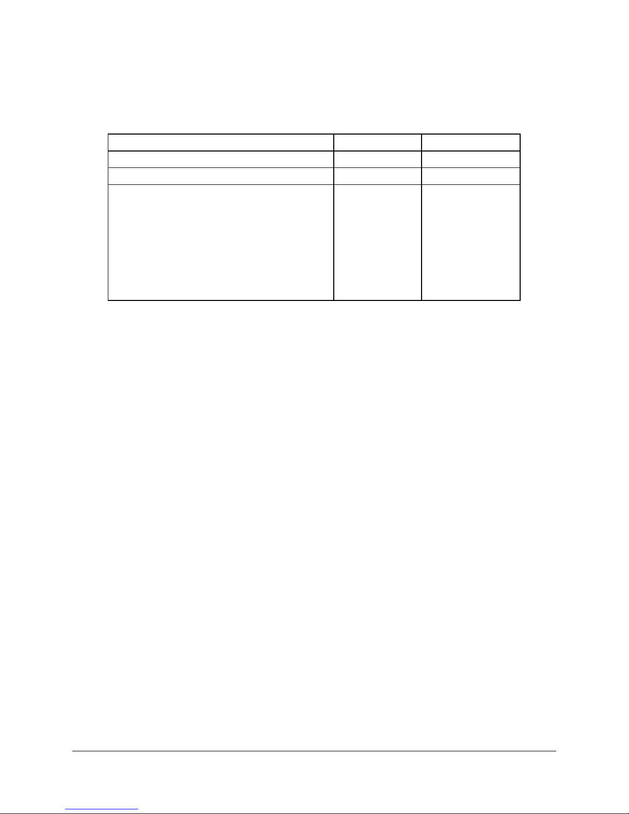
9. Calculated MTBF
The Mean Time Between Failures (MTBF) for the Intel® Entry Storage System SS4000-E is
calculated at 27,248 hours operating at 40 degrees C. The following table shows the MTBF
numbers for individual components within the chassis, and does not include hard disk drives.
Table 15. Intel® Entry Storage System SS4000-E Component MTBF Numbers
Subassembly
(System in 40 oC ambient air)
System Board (D40818-201)
200 W Power Supply 102,997
Hot Swap SATA Backplane (D40817-201)
DC Fan (C76538-001)
Front Panel Ops board 7.792.428
Memory 180,205
MTBF (hours)
66,250
1,214,078
185,347
Revision 1.2 43
Page 50

Page 51

Intel® Entry Storage System SS4000-E Appendix A: Spares and Accessories
Appendix A: Spares and Accessories
Upgrade and Accessory Parts
Table 16. Intel® Entry Storage System SS4000-E Upgrade and Accessory Parts
Product Code MM # Qty. Description
FXX10DVCARBLK
FXXSS4000ECFAN 87928
FXXSS4000EPS
88026
5
4
87928
5
1 Drive Carrier Spare – 10 Pack
1 Fan
1 200 Watt Power Supply
Revision 1.2 45
Page 52

Glossary Intel® Entry Storage System SS4000-E
Glossary
Word / Acronym Definition
A Ampere
AC Alternating Current
ACA Australian Communication Authority
ACPI Advanced Configuration and Power Interface
ANSI American National Standards Institute
ATA AT Attachment
BA Decibel Average
BMC Baseboard Management Controller
BTU British Thermal Units
C Celsius
CF Compact Flash®
CMOS Complementary Metal Oxide Silicon
CPD Component Data Sheet
D2D DC-to-DC
dBA Decibel Average
DDR Double Data Rate
DIMM Dual Inline Memory Module
DMA Direct Memory Access
DOM Disk On Module
ECC Error Correcting Code
EEB Entry-Level Electronics Bay
EEPROM Electrical Erasable Programmable Read-Only Memory
EMC Electro Magnetic Compatibility
EMP Emergency Management Port
ESD Electrostatic Discharge
FC Fibre Channel
FP Front Panel
FRB Fault Resilient Boot
FRU Field Replaceable Unit
FW Firmware
FWH Firmware Hub
G Giga (1.024 x 10⁹)
GB Gigabyte
Gb/s Gigabits per Second
GHz Gigahertz
HBA Host Bus Adapter
HDD Hard Disk Drive
HSBP Hot Swap Backplane
Hz Hertz
IBL Intel Business Link
46
Revision 1.2
Page 53

Intel® Entry Storage System SS4000-E Glossary
IC Integrated Circuit
ICH I/O Controller Hub
IDC Internet Database Connector
IDE Integrated Drive Electronics
IMM Intel® Management Module
I/O Input/Output
iSCSI Internet Protocol Small Computer System Interface
ITE Information Technology Equipment
K Kilo (1.024 x 10³)
KB Kilobyte
KV Kilovolt
KHz Kilohertz
LAN Local Area Network
LED Light-Emitting Diode
LPC Low-Pin Count
MB Megabyte
Mb/s Megabits per second
MCH Memory Controller Hub
MHz Megahertz
mm Millimeter
msec Millisecond
MTBF Mean Time Between Failure
MTTR Mean Time to Repair
NIC Network Interface Card
OTP Over-Temperature Protection
OVP Over-Voltage Protection
PCI Peripheral Component Interconnect
PDB Power Distribution Board
PFC Power Factor Correction
PIO Programmed Input/Output
PLD Programmable Logic Device
PSON Power Supply On
PSU Power Supply Unit
PWT Processor Wind Tunnel
RAID Redundant Array of Inexpensive Disks
RH Relative Humidity
RI Ring Indicate
SAN Storage Area Network
SATA Serial AT Attachment (aka., Serial ATA)
SCA Single Connector Attachment
SCC Storage Control Console
SDR Sensor Data Record
SDRAM Synchronous Dynamic Random Access Memory
SE Single-Ended
SMBIOS System Management Basic Input/Output System
Revision 1.2 47
Page 54

Glossary Intel® Entry Storage System SS4000-E
SOIC Small Outline Integrated Circuit
SRAM Static Random Access Memory
SSI Server System Infrastructure
TQFP Thin Quad F lat Pack
TB Terabyte
UART Universal Asynchronous Receiver Transmitter
μF
μS
USB Universal Serial Bus
V Volt
VA Volt-Amp
VCCI Voluntary Control Council for Interference
VQFP Very Thin Quad Flat Pack
VRM Voltage Regulator Module
W Watt
Micro Farad (1 x 10
Micro Second (1 x 10
-6
Farads)
-6
Second)
48
Revision 1.2
 Loading...