

Page 1

()
X
PRESS5800/140Rc-4
E
Service Guide
Page 2

Page 3

Contents
1 Important Safety Information ........................................................................ 9
Important Safety Information................................................................................................... 9
Intended Application Uses ................................................................................................9
Safety Instructions and Information................................................................................... 9
Checking the Power Cords .............................................................................................10
Multiple Power Cords ...................................................................................................... 10
Earth Grounded Socket-Outlets ...................................................................................... 10
Before You Remove the Access Cover........................................................................... 11
Power Supply Modules ................................................................................................... 11
Fans ................................................................................................................................11
Electrostatic Discharge (ESD)......................................................................................... 11
Cooling and Airflow ......................................................................................................... 12
Lifting and Moving ........................................................................................................... 12
Equipment Rack Precautions..........................................................................................12
Important Set-Up Safety Information..................................................................................... 13
WARNINGS............................................................................................................... 14
2 Getting Started ............................................................................................. 16
Selecting a Site ..................................................................................................................... 16
Space and Power Requirements .................................................................................... 17
General Site Criteria........................................................................................................ 17
Installing Processors, Memory, Hard Disk Drives, and Options............................................ 18
Connecting the Monitor, Keyboard, and Mouse....................................................................18
Turning On the Server and Running the Power-On Self-Test (POST) .................................19
Hot Keys for POST.......................................................................................................... 20
Installing the Maintenance Partition ...................................................................................... 21
Off-line maintenance utility....................................................................................................21
Installing the Operating System ............................................................................................22
The NEC EXPRESSBUILDER CD-ROM .............................................................................. 22
Installing the Server in a Rack ..............................................................................................24
3 Configuration Software and Utilities .......................................................... 25
4 System Management.................................................................................... 26
5 Installing and Removing Components....................................................... 27
Tools and Supplies Needed.................................................................................................. 27
Access Covers ...................................................................................................................... 27
Removing and Installing the Bezel.................................................................................. 28
Removing the Rear Access Cover .................................................................................. 29
Installing the Rear Access Cover .................................................................................... 29
Removing the Front Access Cover ................................................................................. 30
Installing the Front Access Cover ................................................................................... 31
Accessing the System Boards ..............................................................................................31
Removing the Access Cover to the System Boards ....................................................... 32
iii
Page 4

Installing the Access Cover to the System Boards.......................................................... 32
Removing the Memory Board ......................................................................................... 33
Installing the Memory Board ...........................................................................................34
Removing the Processor Board Air Baffle....................................................................... 35
Installing the Processor Board Air Baffle......................................................................... 36
Removing the Processor Board ...................................................................................... 37
Installing the Processor Board ........................................................................................ 38
Removing the Baseboard................................................................................................ 39
Installing the Baseboard.................................................................................................. 41
Processors ............................................................................................................................ 42
Installing Processors ....................................................................................................... 42
Removing Processors ..................................................................................................... 45
Memory ................................................................................................................................. 46
Installing DIMMs.............................................................................................................. 46
Removing DIMMs............................................................................................................48
Hot-Swap SCSI Drives..........................................................................................................49
Checking a Hot-Swap SCSI Drive Status Indicator......................................................... 49
Installing a Hot-Swap Drive in a Carrier .......................................................................... 50
Removing a Hot-swap Drive from a Carrier ....................................................................51
Removing and Installing Hot-Swap Disk Drives.............................................................. 52
DC Power Supplies...............................................................................................................54
Checking the Power Status LEDs ................................................................................... 54
Removing a Power Supply Module ................................................................................. 55
Installing a Power Supply Module ................................................................................... 56
PCI Add-In Boards ................................................................................................................57
Operating System Support for Hot-Plug Add-In Boards..................................................57
Checking the Status Indicators for a Hot-Plug Add-In Board .......................................... 58
Installing a Hot-Plug PCI Add-In Board........................................................................... 59
Removing a Hot-Plug PCI Add-In Board......................................................................... 60
Installing a PCI Add-In Board in a Non-Hot-Plug Slot ..................................................... 61
Removing a PCI Add-In Board from a Non-Hot-Plug Slot...............................................62
Cooling System Fans ............................................................................................................63
Checking a Fan Status Indicator ..................................................................................... 63
Removing a Fan Module ................................................................................................. 64
Installing a Fan Module ................................................................................................... 65
Backup Battery...................................................................................................................... 65
Front Panel Board.................................................................................................................67
Peripheral Drives...................................................................................................................68
Preliminary Considerations ............................................................................................. 68
Installing a 5.25-inch Peripheral Drive ............................................................................ 69
Removing a 5.25-inch Peripheral Drive .......................................................................... 70
Removing a Device from the Media Bay ......................................................................... 70
Installing a Device in the Media Bay ............................................................................... 71
Power Supply Bay................................................................................................................. 72
Replacing the Power Supply Bay.................................................................................... 72
Cooling System.....................................................................................................................74
Removing the Fan Assembly ..........................................................................................74
Installing the Fan Assembly ............................................................................................ 75
Replacing the Fan Board ................................................................................................75
iv
Page 5

Hot-Swap Drive Bay..............................................................................................................76
Removing the Hot-Swap Drive Bay.................................................................................76
Installing a Hot-Swap Drive Bay...................................................................................... 77
Hot-Plug Indicator Board....................................................................................................... 77
Electronics Bay ..................................................................................................................... 78
Removing the Electronics Bay ........................................................................................ 78
Installing the Electronics Bay .......................................................................................... 79
Cable connections.................................................................................................................80
Cable form at maintenance ............................................................................................. 84
6 Solving Problems ......................................................................................... 85
Resetting the System............................................................................................................85
Initial System Startup ............................................................................................................85
Running New Application Software.......................................................................................86
Application Software Checklist........................................................................................ 86
After the System Has Been Running Correctly ..................................................................... 86
Monitoring POST............................................................................................................. 86
Verifying Proper Operation of Key System Lights........................................................... 87
Confirming Loading of an Operating System .................................................................. 87
Specific Problems and Corrective Actions ............................................................................87
Power Light Does Not Light ............................................................................................87
No Beep Codes...............................................................................................................88
No Characters Appear on Screen ................................................................................... 88
Characters Are Distorted or Incorrect .............................................................................88
System Cooling Fans Do Not Rotate Properly................................................................ 89
Diskette Drive Activity Light Does Not Light.................................................................... 89
Hard Drive Activity Light Does Not Light ......................................................................... 89
CD-ROM Drive Activity Light Does Not Light .................................................................. 90
Network Problems........................................................................................................... 90
PCI Installation Tips ........................................................................................................ 91
Problems with Application Software................................................................................ 91
Bootable CD-ROM Is Not Detected ................................................................................ 91
Error Messages..................................................................................................................... 92
Error Messages after Power-on ...................................................................................... 92
POST Error Messages .................................................................................................... 93
Beep Codes ....................................................................................................................99
A Server Description ..................................................................................... 100
Feature Summary ...............................................................................................................100
Technical specifications ...................................................................................................... 101
Chassis Access................................................................................................................... 103
Main Chassis Components .................................................................................................104
Electronics Bay Components .............................................................................................. 105
Front Control Panel.............................................................................................................106
Rear Panel .......................................................................................................................... 107
Peripheral Device Bay......................................................................................................... 107
Hot-Swap Hard Drive Bay ................................................................................................... 108
Power Supplies ................................................................................................................... 109
System Cooling...................................................................................................................109
Server Board Set Features .................................................................................................110
Contents v
Page 6

Baseboard Connector and Component Locations ........................................................ 111
Baseboard Jumpers ...................................................................................................... 112
Processors .................................................................................................................... 114
DIMM Memory............................................................................................................... 114
Onboard Video .............................................................................................................. 114
SCSI Controller ............................................................................................................. 114
Network Interface Controllers........................................................................................ 115
Network Teaming Features........................................................................................... 116
ACPI..............................................................................................................................118
Lamps ................................................................................................................................. 118
POWER/SLEEP Lamp .................................................................................................. 118
STATUS Lamp .............................................................................................................. 119
DISK ACCESS Lamp .................................................................................................... 121
LAN1/LAN2 ACCESS Lamp .........................................................................................121
UID Lamp ...................................................................................................................... 122
Access Lamps...............................................................................................................122
Hard Disk Drive Lamp (DISK Lamp) .............................................................................123
AC Standby Lamp ......................................................................................................... 124
Power Lamp .................................................................................................................. 125
LAN Connector Lamps.................................................................................................. 126
PCI Slot Lamps ............................................................................................................. 127
FAN Fault Lamps .......................................................................................................... 128
Beep Codes ........................................................................................................................ 129
B Error Messages and Error Codes ............................................................. 130
C Equipment Log and Configuration Worksheets...................................... 131
Equipment Log....................................................................................................................131
Calculating Power Consumption ......................................................................................... 133
Index ................................................................................................................. 135
Figures
Figure 1. EXPRESS5800/140Rc-4 Server ............................................................................ 16
Figure 2. Attaching the Bezel to the Chassis ....................................................................... 28
Figure 3. Removing the Rear Access Cover........................................................................29
Figure 4. Removing the Front Access Cover .......................................................................30
Figure 5. Removing the Access Cover to the System Boards ............................................. 32
Figure 6. Removing the Memory Board ............................................................................... 33
Figure 7. Installing the Memory Board .................................................................................34
Figure 8. Removing the Processor Board Air Baffle ............................................................35
Figure 9. Installing the Processor Board Air Baffle ..............................................................36
Figure 10. Removing the Processor Board .......................................................................... 37
Figure 11. Installing the Processor Board............................................................................ 38
Figure 12. Removing the Front Retention Mechanism......................................................... 39
Figure 13. Baseboard Mounting........................................................................................... 40
Figure 14. Correct Order for Populating Processor Sockets................................................42
Figure 15. Raising the Locking Bar...................................................................................... 43
Figure 16. Installing Processors........................................................................................... 43
Figure 17. Installing the Heat Sink ....................................................................................... 44
vi
Page 7

Figure 18. Removing a Processor........................................................................................ 45
Figure 19. Installing Memory................................................................................................47
Figure 20. Removing DIMMs ...............................................................................................48
Figure 21. Hot-Swap SCSI Drive Bay and Status Indicators ...............................................49
Figure 22. Removing a Plastic Air Baffle from a Carrier ......................................................50
Figure 23. Installing a SCSI Hard Disk Drive in a Carrier ....................................................51
Figure 24. Removing a Drive Carrier ...................................................................................52
Figure 25. Installing a Drive Carrier .....................................................................................53
Figure 26. Power and Standby LEDs...................................................................................54
Figure 27. Removing a Power Supply Module.....................................................................55
Figure 28. PCI Add-In Board Locations ...............................................................................57
Figure 29. Status Indicators for Hot-Plug PCI Add-In Boards .............................................. 58
Figure 30. Installing a Hot-Plug PCI Add-In Board............................................................... 59
Figure 31. Removing a Hot-Plug PCI Add-In Board............................................................. 60
Figure 32. Installing and Removing a Non-Hot-Plug PCI Add-In Board............................... 61
Figure 33. Fan Status Indicator............................................................................................ 63
Figure 34. Removing and Installing a Fan Module............................................................... 64
Figure 35. Replacing the Backup Battery............................................................................. 66
Figure 36. Replacing the Front Panel Board........................................................................67
Figure 37. Removing and Installing a 5.25-inch Peripheral Drive ........................................ 69
Figure 38. Removing a Device from the Media Bay............................................................. 71
Figure 39. Power Supply Bay............................................................................................... 72
Figure 40. Removing the Fan Assembly .............................................................................. 74
Figure 41. Replacing the Fan Board .................................................................................... 75
Figure 42. Removing a Hot-Swap Drive Bay .......................................................................76
Figure 43. Removing a Hot-plug Indicator Board.................................................................77
Figure 44. Screw Locations for the Electronics Bay............................................................. 78
Figure 45. Removing the Electronics Bay from the Server Chassis ....................................79
Figure 46. The cable connection of basic configuration....................................................... 80
Figure 47. The cable connection of Disk Array configuration............................................... 81
Figure 48. The cable connection in case of providing rear external VHDCI SCSI port........82
Figure 49. The cable connection in case of providing rear external COM port .................... 83
Figure 50. Caution at Maintenance...................................................................................... 84
Figure 51. EXPRESS5800/140Rc-4 Server Hot-Swap Access ............................................. 103
Figure 52. Chassis with Bezel and Access Covers Removed ...........................................104
Figure 53. Electronics Bay Internal Components...............................................................105
Figure 54. EXPRESS5800/140Rc-4 Front Control Panel......................................................106
Figure 55. EXPRESS5800/140Rc-4 Rear Panel View ..........................................................107
Figure 56. Hard Drive Bay (Bezel Removed).....................................................................108
Figure 57. Baseboard Connector and Component Locations ............................................ 111
Figure 58. Baseboard Jumpers and its default setting....................................................... 112
Tables
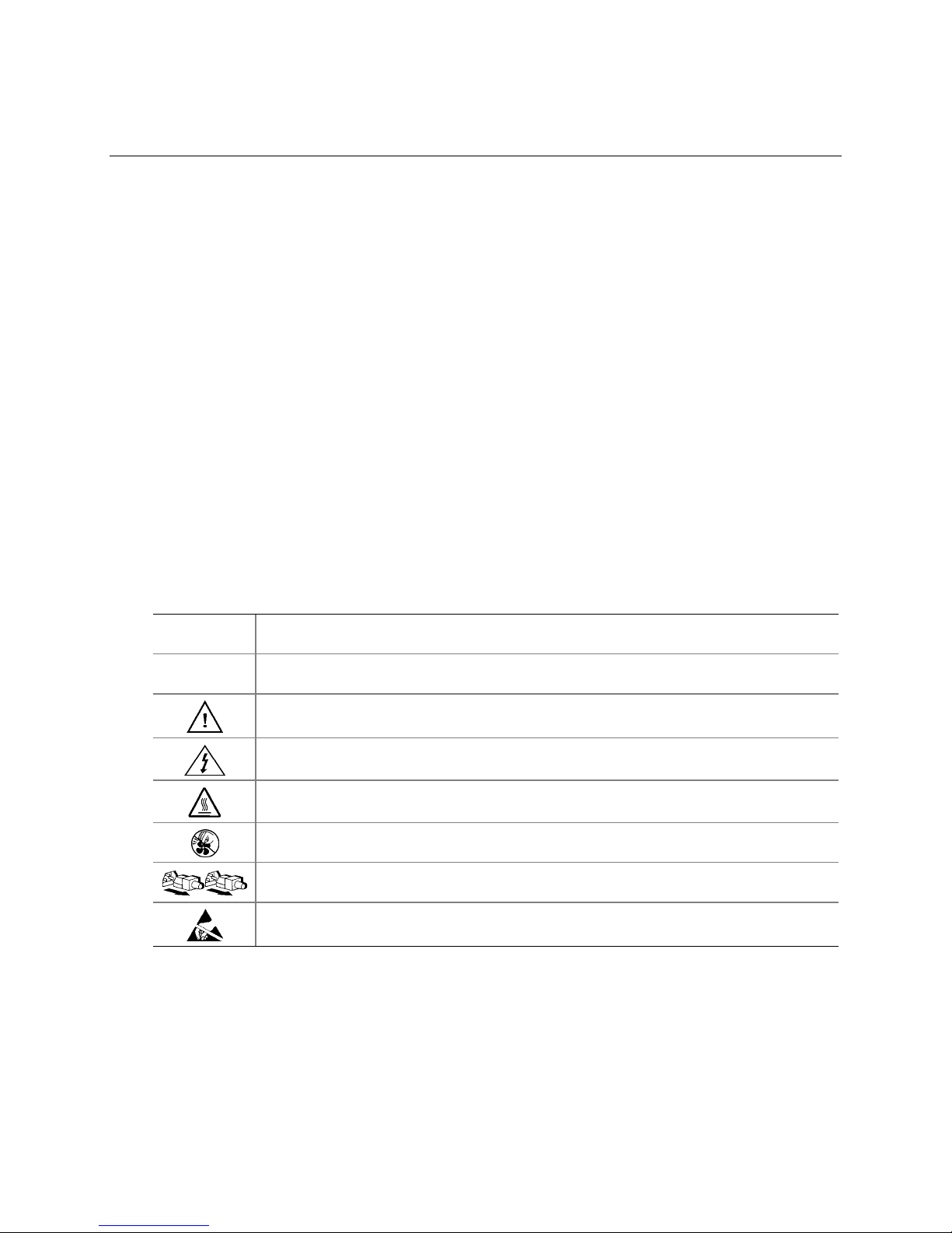
Table 1. Safety Symbols ..................................................................................................... 9
Table 2. EXPRESS5800/140Rc-4 Server Physical Specifications.................................... 17
Table 3. Hot Keys..............................................................................................................20
Table 4. Software Security Features ................................................................................. 23
Table 5. LED States for Hot-Swap SCSI Drive Status ......................................................50
Table 6. LED Power Supply Status Indicators .................................................................. 54
Table 7. LED Hot-Plug PCI Status Indicators.................................................................... 58
Contents vii
Page 8

Table 8. Feature Summary.............................................................................................. 100
Table 9. Front Control Panel Features ............................................................................ 106
Table 10. Server Board Set Features................................................................................ 110
Table 11. Boot Block Jumper Descriptions........................................................................112
Table 12. Main Jumper Descriptions................................................................................. 113
Table 13. Serial Port B Jumper Descriptions.....................................................................113
Table 14. Power Usage Worksheet 1................................................................................ 133
Table 15. Power Usage Worksheet 2................................................................................ 134
viii
Page 9
1 Important Safety Information
Important Safety Information
Only a technically qualified person shall access, integrate, configure, and service this product.
Intended Application Uses
This product was evaluated as Information Technology Equipment (ITE), which may be installed in
offices, schools, computer rooms, and similar commercial type locations. The suitability of this
product for other Product Categories and Environments (such as medical, industrial, alarm systems,
and test equipment), other than an ITE application, may require further evaluation.
Safety Instructions and Information
To avoid personal injury or property damage, before you begin installing the product, read, observe,
and adhere to all of the following safety instructions and information. The following safety
symbols may be used throughout this product guide, and may be marked on the product and or its
packaging.
Table 1. Safety Symbols
CAUTION
WARNING
Indicates the presence of a hazard that may cause minor personal injury or property
damage if the CAUTION is ignored.
Indicates the presence of a hazard that may result in serious injury or death if the
WARNING is ignored.
Indicates potential hazard if hazard symbol is ignored.
Indicates shock hazards that result in serious injury or death if safety instructions are not
followed.
Indicates hot components or surfaces.
Indicates do not touch fan blades, may result in injury.
Indicates product has multiple power cords, and all power cords must be unplugged to
disconnect AC power or mains.
Indicates ESD sensitive components. Use of an antistatic wrist strap connected to ground
is recommended.
9
Page 10

Checking the Power Cords
WARNING
To avoid electrical shock, do not attempt to modify or use the supplied AC
power cord(s), if they are not the exact type required. If a power cord(s)
supplied is not compatible with the AC wall outlet in your region, get one
that meets the following criteria:
• The power cord must be properly rated for the AC voltage in your region.
• The power cord plug cap must have an electrical current rating that is at least
125% of the electrical current rating of the product.
• The power cord plug cap that plugs into the wall socket-outlet must have a
grounding-type male plug designed for use in your region.
• The power cord must have safety certifications for your region, and shall be
marked with the certification markings.
• The power cord plug cap that plugs into the AC receptacle on the power
supply must be an IEC 320, sheet C13, type female connector.
• In Europe, the power cord must be less than 4.5 meters (14.76 feet) long, and
it must be flexible <HAR> (harmonized) or VDE certified cordage to comply
with the chassis’ safety certifications.
The power supply cord(s) is the main disconnect device to AC power. The
socket outlet(s) shall be near the equipment and shall be readily accessible
for disconnection.
Multiple Power Cords
WARNING
To avoid electrical shock, disconnect all AC power cords before accessing
inside the system.
Earth Grounded Socket-Outlets
WARNING
To avoid electrical shock, the system power cord(s) must be plugged into
socket-outlet(s) that is provided with a suitable earth ground. The system
will be provided with the following marking:
Connect only to properly earthed socket outlet.
Apparaten skall anslutas till jordat uttag när den ansluts till ett nätverk.
10
Page 11

Before You Remove the Access Cover
WARNING
To avoid personal injury or property damage, the following safety
instructions apply whenever accessing inside the product:
• Turn off all peripheral devices connected to this product.
• Turn off the system by pressing the power button on the front of the product.
• Disconnect the AC power by unplugging all AC power cords from the
system or wall outlet.
• Disconnect all cables and telecommunication lines that are connected to the
system.
• Retain all screws or other fasteners when removing access cover(s). Upon
completion of accessing inside the product, refasten access cover with
original screws or fasteners.
• Do not access inside power supply. There are no serviceable parts in the
power supply. Return to manufacturer for servicing.
Power Supply Modules
CAUTION
Power supply modules have double-pole/neutral fusing.
Fans
WARNING
To avoid injury do not contact moving fan blades.
Electrostatic Discharge (ESD)
CAUTION
Perform the procedures in this chapter only at an electrostatic discharge
(ESD) workstation, because the server components can be extremely
sensitive to ESD. If no such station is available, you can reduce the risk of
electrostatic discharge ESD damage by doing the following:
• Wear an antistatic wrist strap and attach it to a metal part of the server.
• Touch the metal on the server chassis before touching the server components.
• Keep part of your body in contact with the metal server chassis to dissipate
the static charge while handling the components.
• Avoid moving around unnecessarily.
Important Safety Information 11
Page 12

• Hold the server components (especially boards) only by the edges.
• Place the server components on a grounded, static-free surface. Use a
conductive foam pad if available but not the component wrapper.
• Do not slide the components over any surface.
Cooling and Airflow
CAUTION
For proper cooling and airflow, always install all access covers before
turning on the system. Operating the system for longer than five minutes
without the covers in place can cause overheating and damage to system
components.
Lifting and Moving
CAUTION
Do not attempt to lift or move the server by the handles on the power
supplies.
Equipment Rack Precautions
Follow the rack manufacturer’s safety and installation instructions for proper rack installation. The
following additional rack safety installation measures shall be considered:
ANCHOR THE EQUIPMENT RACK
The equipment rack must be anchored to an unmovable suitable support to
prevent the rack from falling over when one or more systems are fully
extended out of the rack assembly. You must also consider the weight of any
other devices installed in the rack assembly. The equipment rack must be
installed according to the manufacturer's instructions.
MAIN AC POWER DISCONNECT
You are responsible for installing an AC power disconnect for the entire rack
unit. This main disconnect must be readily accessible, and it must be labeled
as controlling power to the entire unit, not just to the system(s).
GROUNDING THE RACK INSTALLATION
To avoid the potential for an electrical shock hazard, the rack assembly itself
must be suitably earth grounded, according to your local regional electrical
codes. This typically will require the rack to have its own separate earth
ground. We recommend you consult your local approved electrician.
12
Page 13

OVER CURRENT PROTECTION
The system is designed to operate on a 20A AC voltage source that is
provided with 20A over current protection. If the AC source for the rack
exceeds 20A over current protection, each system must be provided with
20A or less over current supplemental protection. The supplementary over
current protection must have the appropriate regional safety certifications for
the over current application.
TEMPERATURE LIMITS
The operating temperature of the system, when installed in the rack, must not
go below 10 °C (50 °F) or rise above 35 °C (95 °F). Extreme fluctuations in
temperature may cause a variety of problems in system, and safety limits
may be broken.
VENTILATION CONSIDERATIONS
The equipment rack must provide sufficient airflow to the front of the system
to maintain proper cooling. The rack selected and the ventilation provided
must be suitable to the environment in which the system will be used.
Important Set-Up Safety Information
WARNINGS
Important Safety Information 13
Page 14

WARNINGS
The power supply in this product contains no user-serviceable parts. There may be more than
one supply in this product. Refer servicing only to qualified personnel.
Do not attempt to modify or use the supplied AC power cord if it is not the exact type required.
A product with more than one power supply will have a separate AC power cord for each
supply.
The power button on the system does not turn off system AC power. To remove AC power
from the system, you must unplug each AC power cord from the wall outlet or power supply.
The power cord(s) is considered the disconnect device to the mains (AC) power. The socket
outlet that the system plugs into shall be installed near the equipment and shall be easily
accessible.
SAFETY STEPS: Whenever you remove the chassis covers to access the inside of the
system, follow these steps:
1. Turn off all peripheral devices connected to the system.
2. Turn off the system by pressing the power button.
3. Unplug all AC power cords from the system or from wall outlets.
4. Label and disconnect all cables connected to I/O connectors or ports on the back of the
system.
5. Provide some electrostatic discharge (ESD) protection by wearing an antistatic wrist strap
attached to chassis ground of the system—any unpainted metal surface—when handling
components.
6. Do not operate the system with the chassis covers removed.
After you have completed the six SAFETY steps above, you can remove the system covers.
To do this:
1. Unlock and remove the padlock from the back of the system if a padlock has been installed.
2. Remove and save all screws from the covers.
3. Remove the covers.
For proper cooling and airflow, always reinstall the chassis covers before turning on the
system. Operating the system without the covers in place can damage system parts. To
install the covers:
1. Check first to make sure you have not left loose tools or parts inside the system.
2. Check that cables, add-in boards, and other components are properly installed.
3. Attach the covers to the chassis with the screws removed earlier, and tighten them firmly.
4. Insert and lock the padlock to the system to prevent unauthorized access inside the system.
5. Connect all external cables and the AC power cord(s) to the system.
continued
14
Page 15
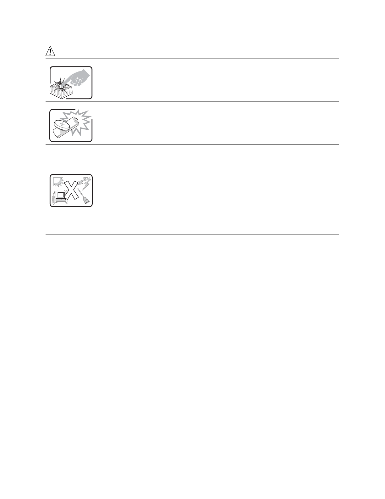
WARNINGS (Continued)
A microprocessor and heat sink may be hot if the system has been running. Also, there may
be sharp pins and edges on some board and chassis parts. Contact should be made with
care. Consider wearing protective gloves.
Danger of explosion if the battery is incorrectly replaced. Replace only with the same or
equivalent type recommended by the equipment manufacturer. Dispose of used batteries
according to manufacturer’s instructions.
The system is designed to operate in a typical office environment. Choose a site that is:
• Clean and free of airborne particles (other than normal room dust).
• Well ventilated and away from sources of heat including direct sunlight.
• Away from sources of vibration or physical shock.
• Isolated from strong electromagnetic fields produced by electrical devices.
• In regions that are susceptible to electrical storms, we recommend you plug your system
into a surge suppresser and disconnect telecommunication lines to your modem during an
electrical storm.
• Provided with a properly grounded wall outlet.
• Provided with sufficient space to access the power supply cord(s), because they serve as
the product’s main power disconnect.
Important Safety Information 15
Page 16
2 Getting Started
This section discusses the main steps you need to perform to get your server up and running:
1. Select an appropriate site.
2. Install processors, memory, hard disk drives, and other options.
3. Connect the monitor, keyboard, and mouse.
4. Turn on the server and boot to the NEC EXPRESSBUILDER CD-ROM.
5. Install the service partition.
6. Install an operating system.
7. Set up system security.
8. Install the server into a rack unit.
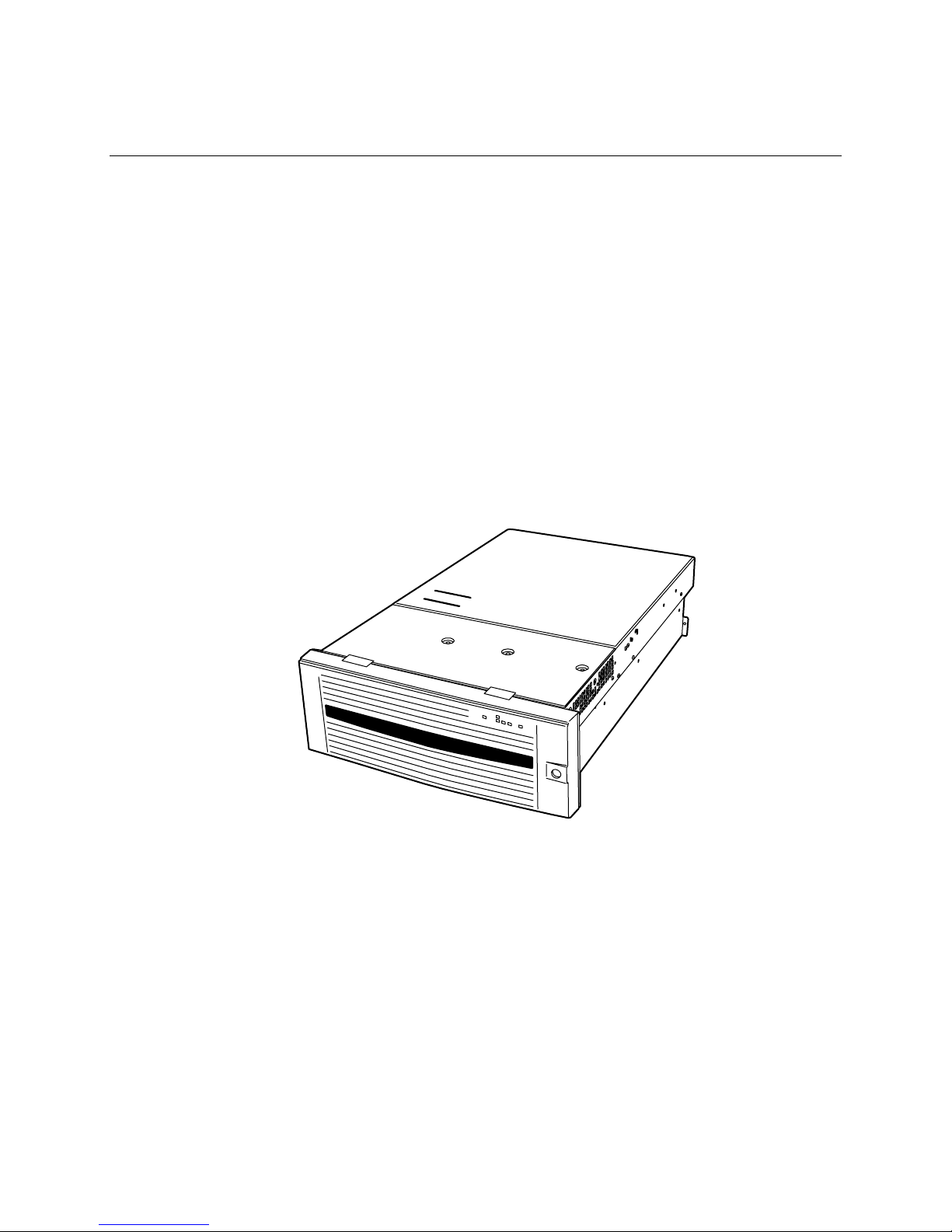
Selecting a Site
This section describes the space and power requirements and general site criteria for installing the
server.
Figure 1. EXPRESS5800/140Rc-4 Server
16
Page 17

Space and Power Requirements
Table 2. EXPRESS5800/140Rc-4 Server Physical Specifications
Specification Rack Mode Only
Height 7 inches (178 mm) (4u)
Width 17.5 inches (445 mm)
Depth 28.0 inches (711 mm)
Weight 57 pounds (25.9 kg), minimum configuration
77 pounds (35.0 kg), maximum configuration
Required front clearance 3 inches (76 mm), inlet airflow <35 °C (95 °F)
Required rear clearance 4.5 inches (114 mm), no airflow restriction
Required side clearance 1 inch (25 mm)
Power requirements
Voltage (110)
Voltage (220)
Frequency
For detailed information on calculating power consumption for specific server configurations, see
page 133.
90 V
180 V
47 Hz min, 63 Hz max
* Amperage is total system power, with two or three power supply modules
installed, with one or two AC cords.
min, 132 V
rms
min, 264 V
rms
max, 8 A
rms
rms
max, 4 A
rms
rms
*
*
General Site Criteria
The server operates reliably within normal office environmental limits. Select a site that meets
these criteria:
• Near a properly grounded, three-pronged power outlet.
In the United States and Canada: a NEMA 6-15R outlet for 100-120 V and for 200-240 V.
In other geographic areas: a properly grounded outlet in accordance with the local
electrical authorities and electrical code of the region.
• Clean and relatively free of excess dust.
• Well ventilated and away from sources of heat, with the ventilating openings on the server kept
free of obstructions.
• Maximum ambient air temperature should not exceed 35 °C (95 °F).
• Away from sources of vibration or physical shock.
• Isolated from strong electromagnetic fields and noise caused by electrical devices such as
elevators, copy machines, air conditioners, large fans, large electric motors, radio and TV
transmitters, and high-frequency security devices.
• Access space provided so the server power cords can be unplugged from the power supply or
the wall outlet; this is the only way to remove AC power from the server.
• Clearance provided for cooling and airflow.
Getting Started 17
Page 18

NOTES
✏
Surge suppressor recommended: In geographic regions that are
susceptible to electrical storms, NEC strongly recommends that you plug the
server into a surge suppressor..
Installing Processors, Memory, Hard Disk Drives, and
Options
The server is shipped without processors, memory, or hard drives. To install the memory,
processors, hard drives, and other options, follow the steps shown in “N8100-821F NEC
Express5800/140Rc-4 User’s Guide” (856-121794-502-00) that is included with the server. For
more information on any of the steps listed on the guide, see the references below:
1. Removing the covers:
a. Removing the rear access cover—see page 29.
b. Removing the access cover to the system boards—see page 32.
2. Removing the memory and processor boards:
a. Removing the memory board—see page 33.
b. Removing the air baffle—see page 35.
c. Removing the processor board—see page 37.
3. Installing memory and processors:
a. Installing the DIMMs in the memory board—see page 46.
b. Installing the processors on the processor board—see page 42.
4. Installing an ICMB board—follow the instructions that came with the ICMB board kit.
5. Installing the processor and memory boards:
a. Installing the processor board on the baseboard—see page 38.
b. Installing the air baffle—see page 36.
c. Installing the memory board—see page 34.
6. Installing PCI add-in cards—see page 57. For a description of the PCI slots, see Figure 28 on
page 57.
7. Installing hard disk drives—see page 49.
8. Installing an additional power supply or additional peripherals—see page 54, page 68, and any
additional documentation that came with the peripherals.
9. Installing covers:
a. Installing the access cover to the system boards—see page 32.
b. Installing the rear access cover—see page 29.
10. Configuring your system—complete the remainder of this “Getting Started” section.
Connecting the Monitor, Keyboard, and Mouse
Connect the monitor, keyboard, and mouse to the appropriate connectors on the rear panel of the
server. See Figure 55 on page 107.
You have completed the hardware setup. The remainder of this section discusses software setup
and configuration.
18
Page 19

Turning On the Server and Running the Power-On
Self-Test (POST)
Each time you start the server, the Power-On Self-Test (POST) runs automatically. POST is stored
in flash memory.
To start the server, do the following:
NOTE
✏
To access certain features, such as BIOS Setup, you must press specific keys
at specific times during POST. To familiarize yourself with this procedure,
read the following instructions through completely before actually
performing them. For a summary of hot keys active during POST, see
Table 3 on page 20.
1. Make sure all external devices, such as a monitor, keyboard, and mouse, are connected.
2. If a drive protection card or diskette is present in the diskette drive, remove it.
3. Plug the video monitor power cord into the power source or wall outlet. Turn on the video
monitor.
4. Plug the AC power cords into the power connectors on the back of the chassis and into the
power source or wall outlet.
5. If the server does not turn on when you plug it into the AC outlet, press the on/off power button
on the front panel.
6. Verify that the main power LED on the front panel is lit (see Figure 54 on page 106).
7. Insert the NEC EXPRESSBUILDER CD into the CD-ROM drive.
After a few seconds, POST begins and a splash screen is displayed (if the splash screen is
disabled in BIOS Setup, a diagnostics screen is displayed). POST discovers, configures, and
tests the processors, memory, keyboard, and most installed peripheral devices. The length of
time needed to complete POST depends on the amount of memory installed and the number of
option boards installed.
8. Shortly after the splash screen is displayed, POST displays the message “Press <F2> to enter
Setup…” at the bottom of the screen. At this point, you can press any of the keys identified
with an asterisk (*) in Table 3 on page 20, or you can do nothing and wait until the server boots
from the CD-ROM. If you enter BIOS Setup, the Maintenance Partition, or the Adaptec
SCSISelect
9. After POST completes, the system beeps once and then searches all boot devices in the order
defined by the boot priority settings in the BIOS. The system finds, loads, and runs the limited
operating system on the NEC EXPRESSBUILDER CD.
†
Utility, when you exit those features, the server might reboot.
†
NOTE
✏
If there is no device with a bootable operating system, the boot process
continues, the system beeps once, and the following message is displayed:
Operating System not found
Getting Started 19
Page 20

If you have a device with a bootable operating system but see this message
anyway, reboot and use BIOS Setup to make sure your boot device settings
are correct.
Hot Keys for POST
Table 3 lists the hot keys you can use during POST to access setup utilities and alter the normal
POST execution.
Table 3. Hot Keys
To Do This: Press These Keys:
Abort memory test during POST. <Space>
Press while BIOS is updating memory size on screen.
Resume after a POST error is displayed. (The
system pauses after displaying an error.)
Enter BIOS Setup during POST. <F2>*
Boot to the service partition. <F4>*
Boot from a network using Preboot Execution
Environment (PXE).
Remove the splash screen to view the diagnostic
messages during POST and display a menu for
selecting the boot device.
Enter the Adaptec SCSISelect Utility during POST. <Ctrl+A>*
* Press any of these keys when the prompt “Press <F2> to enter Setup…” is displayed.
<F1>
<F12>*
<ESC>*
Note: Using BIOS Setup, you can enable the
Boot-Time Diagnostic Screen, in which case POST
does not display the splash screen.
Note: If you use the displayed menu to change the
boot device, the change affects the current boot only.
20
Page 21

Installing the Maintenance Partition
When you need the installation for Maintenance utilities, please see in “EXPRESS BUILDER CD
3.091 A-N” (363-01632-000)
Off-line maintenance utility
The off-line maintenance utility can be started by various methods. Although an off-line
maintenance utility can also be started manually, it can also be made to start automatically at the
time of obstacle generating.
1. The starting up of the off-line maintenance utility
For more detail information, please see in “EXPRESS BUILDER CD 3.091 A-N” (363-01632-000)
The starting up with NEC EXPRESSBUILDER
The starting up with FDD
The manual starting up (push F4 key)
The starting up with NEC ESM PRO
The automatic starting up (at obstacle under OS operating)
The automatic staring up (at failure under OS booting)
2. The function of the off-line maintenance utility
An off-line maintenance utility enables execution of the following functions.
Indication of IPMI information
Indicating and Backing-up information for System Event Log (SEL), Sensor Data Record
(SDR), and Field Replaceable Unit (FRU).
Indication of BIOS setting information
Indicating the current setting BIOS information, and down-loading it to a text file.
Indication of system environments
Indicating the concerning information for processor and BIOS, and down-loading them to a
text file.
Getting Started 21
Page 22

Management of system environments
Back-up the information for customer’s file property on system. This back-up is absolutely
needed for system restoration at change of board from maintenance. However there are the
possible information, the impossible information, and the unnecessary information on Backup. After exchange, the information which is not able to back up will be initialized. Therefore,
surely, please check it before exchange and restore after exchange manually.
* the back-up possible information
>the product information on FRU (Model name, NEC manufacturing code, Field
Revision, serial number of system unit, etc…)
>the chassis frame information on FRU (the NEC part number for chassis frame)
>the contents of BIOS setting
>the contents of BMC/RomPilot
* the back-up impossible information
>the contents of SCSI BIOS setting
>the setting contents for any optional boards
* the back-up unnecessary information
>the board information on FRU (NEC part numbers, Compatibility Revision, serial
number, etc…)
>the MAC address for onboard LAN
The starting up from each utilities
Enable starting up the utility of the following installed to the maintenance partition from
NEC EXPRESSBUILDER.
* System management function
* System diagnosis
* Setting maintenance partition
Installing the Operating System
When you need the installation for any software, please in “EXPRESS BUILDER CD 3.091 A-N”
(363-01632-000)
The NEC EXPRESSBUILDER CD-ROM
For more information regarding NEC EXPRESSBUILDER CD-ROM , please refer to the Online
document in in “EXPRESS BUILDER CD 3.091 A-N” (363-01632-000)
22
Page 23

• System Security
Table 4 summarizes the security features provided by the BIOS to prevent unauthorized or
accidental access to the system. You can enable these features using the Security section of BIOS
Setup. Additional information on passwords is provided following the table.
Table 4. Software Security Features
Feature Description
Secure Mode
Secure Mode Boot
Password on Boot
To enable secure mode: Set a user password.
To enter secure mode, do one of the following:
• Press the hot-key combination for secure mode. You can specify a hot-key
combination, which must consist of Ctrl+Alt plus one alphanumeric character.
• Let the inactivity timer time out. If you don’t touch the keyboard during the
time-out period, the system enters secure mode automatically. You can set the
time-out period from two minutes to 120 minutes.
• Power on or reset the system. The system automatically enters secure mode
on power up.
When the system is in secure mode:
• Onboard video is blanked, if enabled.
• Diskette drive is write protected, if enabled.
• Power, Sleep, and Reset buttons on the front panel are disabled.
• Mouse and keyboard input are ignored, except for entering a password.
• The keyboard LEDs flash.
To enable, do both of the following:
• Set a user password.
• Enable Secure Mode Boot.
To activate: Power on or reset the server.
When enabled:
• If booting from drive A: the user must enter a password. After the user enters
the password, the system continues with the boot process. The system doesn’t
enter secure mode until activated by the hot-key or timer.
• If the system is not booting from drive A: the system boots normally. No
password is required, and the system enters secure mode automatically.
The system boots according to the boot device priority set in BIOS Setup.
To enable, do all of the following:
• Set a user password.
• Enable Password on Boot.
• Disable Secure Mode Boot.
To activate: Power on or reset the server.
When enabled: The user must enter a password to boot the system. The system
boots according to the boot device priority set in BIOS Setup.
continued
Getting Started 23
Page 24

Table 4. Software Security Features (Continued)
Feature Description
Fixed Disk Boot
Sector Write Protect
Power Switch Inhibit
To enable, do the following:
• Set Fixed Disk Boot Sector to Write Protect in the Security section of BIOS
Setup.
To activate: Power on or reset the server.
When enabled: Write protects the master boot record of the IDE hard disk drive
when the system boots from drive A:. Prevents viruses from corrupting the boot
sector under DOS. Works only with IDE drives.
To enable: Enable Power Switch Inhibit.
To activate: Power on or reset the server.
When enabled: The power switch can’t be used to power off the system.
Using Passwords
Passwords are up to seven characters long; may use only the alphanumeric characters a-z, A-Z, and
0-9; and are not case sensitive.
You set administrator and user passwords in BIOS Setup. When you have either password set, you
must enter that password to do any of the following:
• Enter BIOS Setup.
• Boot the server from drive A: when Secure Boot Mode is enabled.
• Boot the server when Password on Boot is enabled.
• Exit secure mode.
When you have both a user and an administrator password set, you may enter either password.
However, if you enter the user password for BIOS Setup, you will be able to modify only the time,
date, language, user password, secure mode timer, and secure mode hot-key. To modify any other
features, you must enter the administrator password.
You can clear a password by setting it to a blank string. If you forget your passwords, you can use
the Password Clear jumper to clear the passwords on the next boot (see “Baseboard Jumpers” on
page 112).
Installing the Server in a Rack
The server mounts in a rack using a Rack Mount Kit. For information on rack mount kits and the
specifications for compatible racks, see “N8100-821F NEC Express5800/140Rc-4 User’s Guide”
(856-121794-502-00).
Install the Rack Mount Kit following the instructions on the back of “N8100-821F NEC
Express5800/140Rc-4 User’s Guide” (856-121794-502-00) and the instructions that came with the
kit.
When installing or removing the server from the rack, use an appropriate mechanical assist unit to
lift and move the server.
24
Page 25

3 Configuration Software and Utilities
When you need the settings for configuration of the following software and utilities, please see
“N8100-821F NEC Express5800/140Rc-4 User's Guide” (856-121794-502-00):
• BIOS Setup—for modifying server board set features, including setting time, date, and system
passwords; setting the boot device priority; configuring the diskette drive and serial ports; and
enabling the SCSI BIOS and system management features.
• SCSISelect—for configuring the onboard SCSI host adapter, including changing default
values, checking and changing SCSI device settings that might conflict with those of other
devices in the server, and performing a low-level format on SCSI devices installed in the
server.
Additional utilities for system management are described on page 26.
25
Page 26

4 System Management
NEC integrates system management features into the hardware and provides additional features
through NEC Express System Management PRO (NEC ESM PRO). When you need this integration
for hardware features, please see in “EXPRESS BUILDER CD 3.091 A-N” (363-01632-000)
26
Page 27

5 Installing and Removing Components
Tools and Supplies Needed
• Phillips† screwdriver
• Small flat-bladed screwdriver
• Antistatic wrist strap and conductive foam pad (recommended)
• Pen or pencil
• Equipment log (page 131)
As you integrate new parts into the system, record the model and serial number of the server system,
all installed options, and any other pertinent information specific to the server system.
Access Covers
This section includes instructions for the following:
• Removing and installing the bezel
• Removing and installing the rear access cover
• Removing and installing the front access cover
Installing and Removing Components 27
Page 28
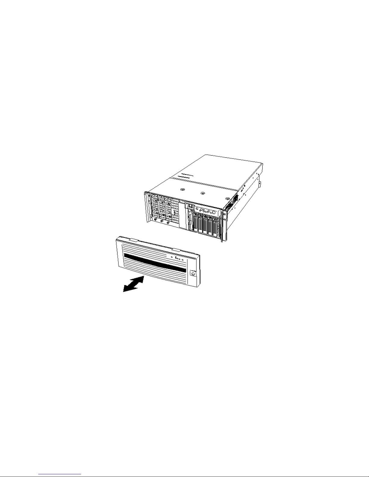
Removing and Installing the Bezel
You need to remove the bezel to install and remove hot-swap power supplies and to install and
remove devices in the 5.25-inch peripherals bay. The bezel has ball studs (Figure 2, A) on the back
that snap-fit into holes on the chassis front.
• To remove the bezel,
1. Unlock the security key
2. Grasp the right edge of the front bezel and pull the bezel towards you to open it.
3. Slide the front bezel left to disengage the mounting tabs and remove the front bezel from the
chassis.
• To install the bezel, Position the front bezel so the mounting tabs of the front bezel are aligned
with their mounting holes on the front of the system. Slide the bezel right until the bezel snaps
into place.
28
Figure 2. Attaching the Bezel to the Chassis
Page 29
Removing the Rear Access Cover
The rear access cover provides access to the hot-swap fans and to the electronics bay that contains
PCI add-in cards and the server board set. To remove the cover:
1. Release the captive screws located on the rear edge of the cover (Figure 3).
2. While lightly pressing down on the cover, slide it toward the rear of the chassis.
3. Lift the cover up and off of the chassis.
Figure 3. Removing the Rear Access Cover
Installing the Rear Access Cover
NOTE
✏
Before installing the rear access cover, check that you have not left tools or
loose parts inside the system.
To install the rear access cover:
1. Position the cover on the chassis so that the cover tabs align with the chassis slots.
2. While lightly pressing down on the cover, slide it toward the front of the chassis until the cover
tabs fully engage the chassis slots.
3. Attach the cover to the chassis with the captive screws located on the rear edge of the cover.
Installing and Removing Components 29
Page 30
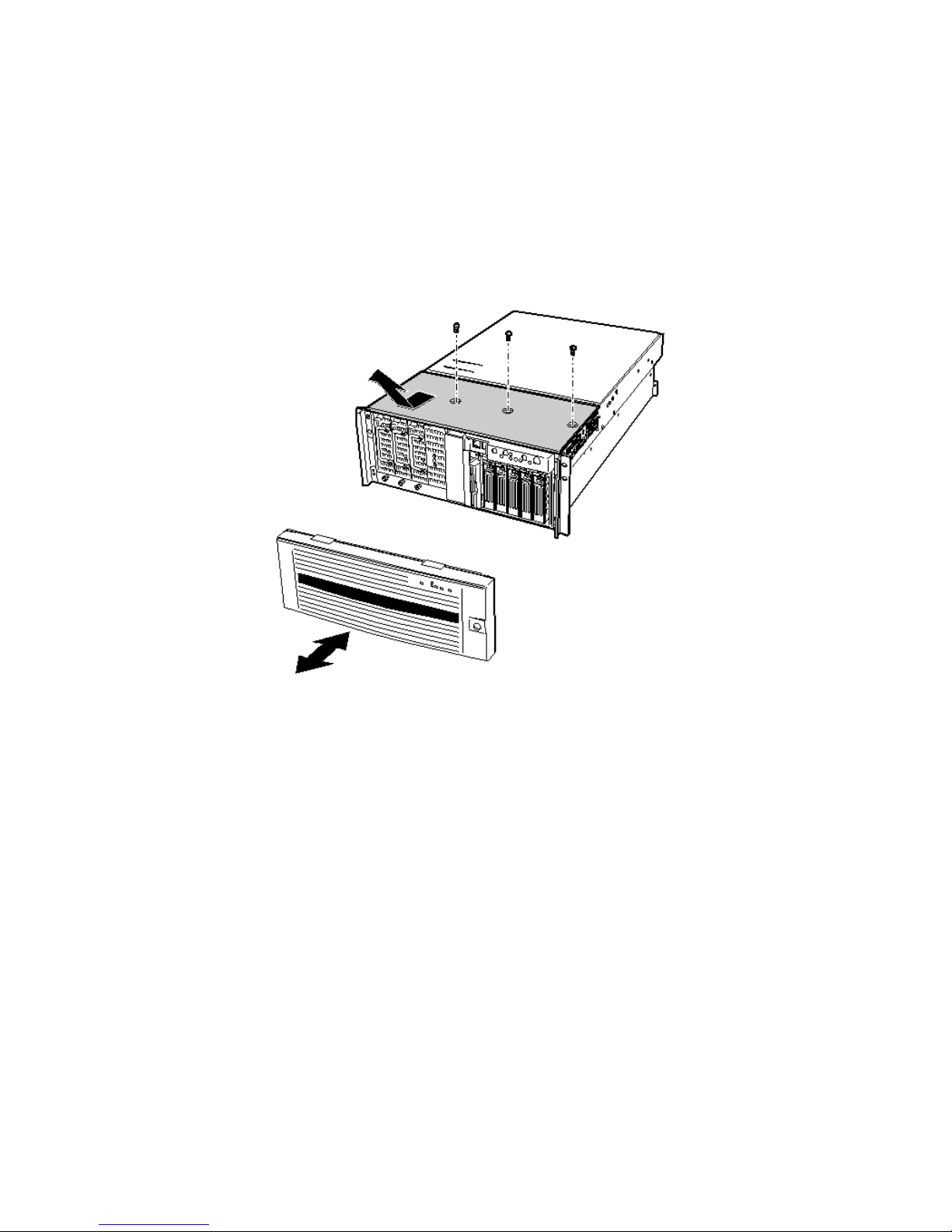
Removing the Front Access Cover
To install or remove devices in the peripherals bay and to install or remove the hot-swap drive bay or
power supply bay, you need to remove the front access cover. To remove the front access cover:
1. Remove the three cover screws, as shown in Figure 4.
2. While lightly pressing down on the cover, slide it toward the front of the chassis.
3. Lift the cover up and off of the chassis.
Figure 4. Removing the Front Access Cover
30
Page 31

Installing the Front Access Cover
NOTE
✏
Before installing the front access cover, check that you have not left tools or
loose parts inside the system.
To install the front access cover:
1. Position the cover on the chassis so that the cover tabs align with the chassis slots.
2. While lightly pressing down on the cover, slide it toward the rear of the chassis until the cover
tabs fully engage the chassis slots.
3. Attach the cover to the chassis with the three screws removed earlier.
Accessing the System Boards
This section includes instructions for the following:
• Removing and installing the access cover to the system boards
• Removing and installing the memory board
• Removing and installing the processor board air baffle
• Removing and installing the processor board
• Removing and installing the baseboard
Installing and Removing Components 31
Page 32
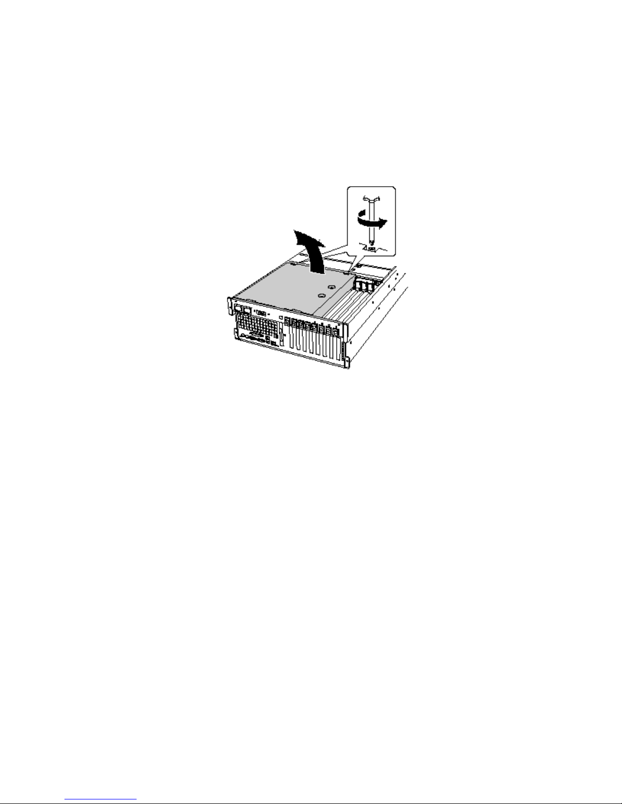
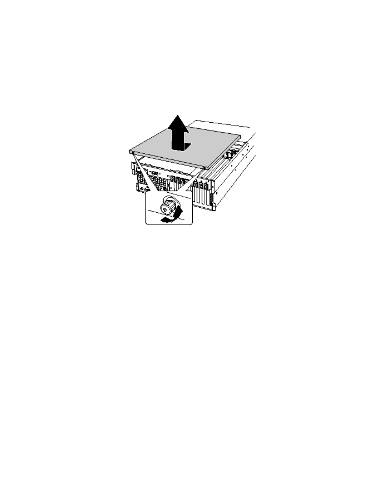
Removing the Access Cover to the System Boards
To remove the access cover to the system boards:
1. Remove the rear access cover (page 29).
2. Loosen the two captive screws located at the front of the access cover to the system boards
(Figure 5).
3. Lift the end of the cover where the screws are located and remove the cover.
Figure 5. Removing the Access Cover to the System Boards
Installing the Access Cover to the System Boards
To install the access cover:
1. Orient the access cover with the captive screws toward the front of the server.
2. Insert the tabs on the rear of the cover into the slots at the rear of the chassis.
3. Press down gently and tighten the captive screws at the front of the cover.
32
Page 33

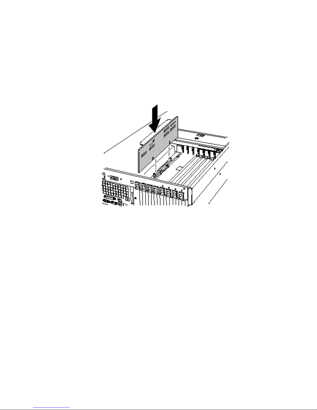
Removing the Memory Board
To remove the memory board:
1. Grasp the bracket on the top edge of the memory board and pull straight up until the board
disengages from the connector on the processor board (Figure 6).
2. Lift the memory board out of the chassis.
Figure 6. Removing the Memory Board
Installing and Removing Components 33
Page 34
Installing the Memory Board
To install the memory board:
1. Holding the bracket on the top edge of the memory board, insert the board into the guides at both
ends of the electronics bay.
2. Align the memory board with the connector on the processor board and press down on the
bracket until the board is fully inserted into the connector.
Figure 7. Installing the Memory Board
34
Page 35

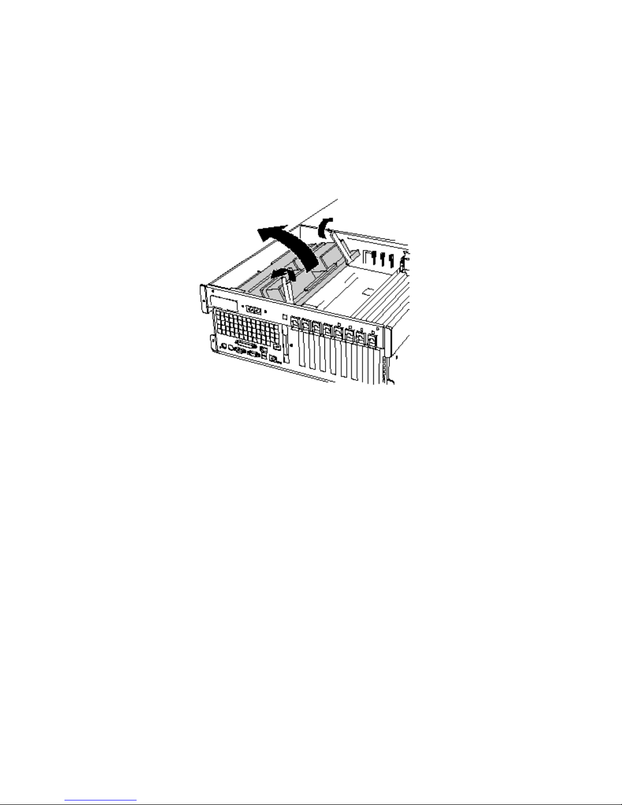
Removing the Processor Board Air Baffle
To remove the processor board air baffle:
1. Remove the screw holding the dual power receptacle (located at the top left rear of the chassis)
and pull it clear of the chassis as far as the attached cords will allow (Figure 8, A and B).
2. At the end of the air baffle closest to the rear of the chassis, press the two tabs toward each other
(Figure 8, D) and raise the end, rotating the baffle about 30°.
3. Disengage the air baffle at the front of the electronics bay and remove the baffle from the
chassis.
A Power receptacle screw C Air baffle
B Dual power receptacle D Release tabs on air baffle
Figure 8. Removing the Processor Board Air Baffle
Installing and Removing Components 35
Page 36

Installing the Processor Board Air Baffle
To install the processor board air baffle:
1. Orient the baffle so that the two release tabs are toward the rear of the chassis (Figure 9).
2. With the rear of the air baffle raised, insert the tab on the front of the air baffle into the slot in the
chassis. Holding the baffle at an angle of about 30° will allow the tab to engage correctly.
3. Holding the power receptacle and attached cords clear, rotate the rear end of the baffle down.
Adjust the position of the baffle until it moves into place and the two tabs are engaged. Do not
force it down.
4. Move the power receptacle into place and attach the receptacle using the screw.
Figure 9. Installing the Processor Board Air Baffle
36
Page 37
Removing the Processor Board
To remove the processor board:
1. Rotate the handles on the processor board until they are fully open (Figure 10).
2. Using the handles, tilt the processor board up and remove it from the chassis.
Figure 10. Removing the Processor Board
Installing and Removing Components 37
Page 38

Installing the Processor Board
To install the processor board:
1. Insert the tabs on the processor board into the slots on the baseboard bracket (Figure 11, A).
2. With the handles in the open position, lower the processor board until it rests on the baseboard
bracket.
3. Close and press down on the handles until the processor board is fully engaged with the sockets
on the baseboard.
Figure 11. Installing the Processor Board
38
Page 39

Removing the Baseboard
To remove the baseboard:
1. Remove all external cables from the baseboard I/O ports at the back of the chassis.
2. Remove the fan assembly (page 74).
3. Label and disconnect all internal cables connected to the PCI add-in boards.
4. Remove all PCI add-in boards (pages 60 and 62).
5. Plastic curtains run the length of the electronics bay separating the PCI add-in cards. Remove
the curtains as follows:
a. Release one end of the curtain from the front retention mechanism. Lift the free end high
enough to clear the chassis.
b. From outside of the rear of the chassis, push down on the other end of the curtain and pull
the free end out of the chassis.
6. Label and remove all internal cables attached to connectors on the board. For a diagram showing
labeled connectors, see Figure 57 on page 111. Remove all cables from the cable retention clip
on the front of the electronics bay.
7. A plastic retention mechanism for the PCI add-in cards is fastened to the front of the electronics
bay by three clips (Figure 12, A). Release each clip by pressing down on the tab and remove the
retention mechanism.
A Tabs (3) on retention mechanism C Overlay tab (1 of 2)
B Protective overlay D Overlay screw
Figure 12. Removing the Front Retention Mechanism
Installing and Removing Components 39
Page 40

8. Remove the plastic protective overlay covering the PCI area of the board as follows:
a. Unscrew the captive screw holding the overlay in place (Figure 12, D).
b. Near the middle of the baseboard, lift the edge of the overlay until it is clear of the
connectors on the board (Figure 12, B).
c. Slide the overlay toward the front of the electronics bay and unhook it from the two tabs
(Figure 12, C).
d. Remove the overlay.
9. Remove the six screws, the plastic overlay, and the two processor board mounting brackets that
attach the baseboard to the electronics bay (Figure 13, A).
Figure 13. Baseboard Mounting
10. Lifting the board slightly, slide the baseboard toward the front of the chassis until the I/O ports
clear the chassis.
11. At one side of the chassis, the board is inserted into slots in a foam panel (Figure 13, B). Lift up
on the opposite end of the board and pull the edge of the board out of the slots in the foam panel.
12. Lift the baseboard out of the electronics bay and place it component-side up on a nonconductive,
static-free surface (or in an antistatic bag).
40
Page 41

Installing the Baseboard
To install the baseboard:
1. With the rear of the electronics bay closest to you and the baseboard oriented so that the I/O
connectors line up with the cutout in the back left of the chassis (Figure 13, above), lower the
right end of the baseboard into the electronics bay and slip the board edge into the slots of the
foam panel (Figure 13, B, above).
2. Lower the other end of the baseboard to the floor of the electronics bay and slide it toward the
back of the chassis until:
a. The I/O connectors fit all of the way into the I/O connector openings.
b. The six mounting holes (Figure 13, A, above) on the baseboard are aligned with their
corresponding threaded standoffs in the floor of the electronics bay.
3. Install the processor board mounting brackets and processor-side plastic overlay as follows:
a. Align the processor board mounting bracket for the center of the baseboard with the three
mounting holes. Insert a screw through each of the holes and partially thread the screws into
the standoffs.
b. Align the other mounting bracket along the edge of the board. Align the plastic overlay with
the bracket and the two plastic studs. Insert a screw through each of the holes in the overlay
and mounting bracket and partially thread the screws into the standoffs.
c. Adjust the board position as needed and tighten the six screws.
4. Install the plastic protective overlay covering the PCI area of the board as follows:
a. At the side of the electronics bay where the edge of the baseboard is inserted into the foam,
place the two slots in the overlay over the hooked tabs (Figure 12, C, on page 39).
b. Slide the overlay toward the rear of the chassis to hook the tabs in the slots.
c. Carefully fit the overlay around the baseboard connectors and down against the board.
d. Tighten the captive screw that holds the overlay in place.
5. Install the front retention mechanism for the PCI add-in cards on the front wall of the electronics
bay (Figure 12 on page 39).
6. Connect all internal cables to the baseboard.
7. Install the PCI add-in board curtains as follows:
a. At the back of the electronics bay, slide the end of a curtain with the locking tab into the
topmost square hole adjacent to any add-in board expansion slot.
b. At the front of the electronics bay, slide the tab at the other end of the curtain into the clip on
the corresponding retention mechanism.
8. Install all PCI add-in boards and attach any internal cables to the boards.
9. Install the fan assembly in the main server chassis.
10. Attach the external cables to the baseboard I/O ports.
Installing and Removing Components 41
Page 42

Processors
This section includes instructions for installing and removing processors and heat sinks. For a list of
supported processors, call your service representative.
Installing Processors
To install processors:
1. Observe the safety and ESD precautions at the beginning of this document.
NOTE
✏
You must install a processor in processor socket 1. When installing multiple
processors, populate the processor sockets in the order shown in Figure 14.
Figure 14. Correct Order for Populating Processor Sockets
CAUTION
If you are not using processor sockets 3 and 4, leave the foam block in place.
The block is required for proper airflow for cooling the processors.
42
Page 43

2. Raise the locking bar on the socket.
N
G OK
Figure 15. Raising the Locking Bar
3. Orient the processor so that the triangle on the corner of the processor aligns with the triangle on
the corner of the socket (Figure 16).
4. Aligning the pins of the processor with the socket, insert the processor into the socket. The
processor should drop into the socket without requiring any force.
5. Lower the locking bar completely.
Installing and Removing Components 43
Figure 16. Installing Processors
Page 44
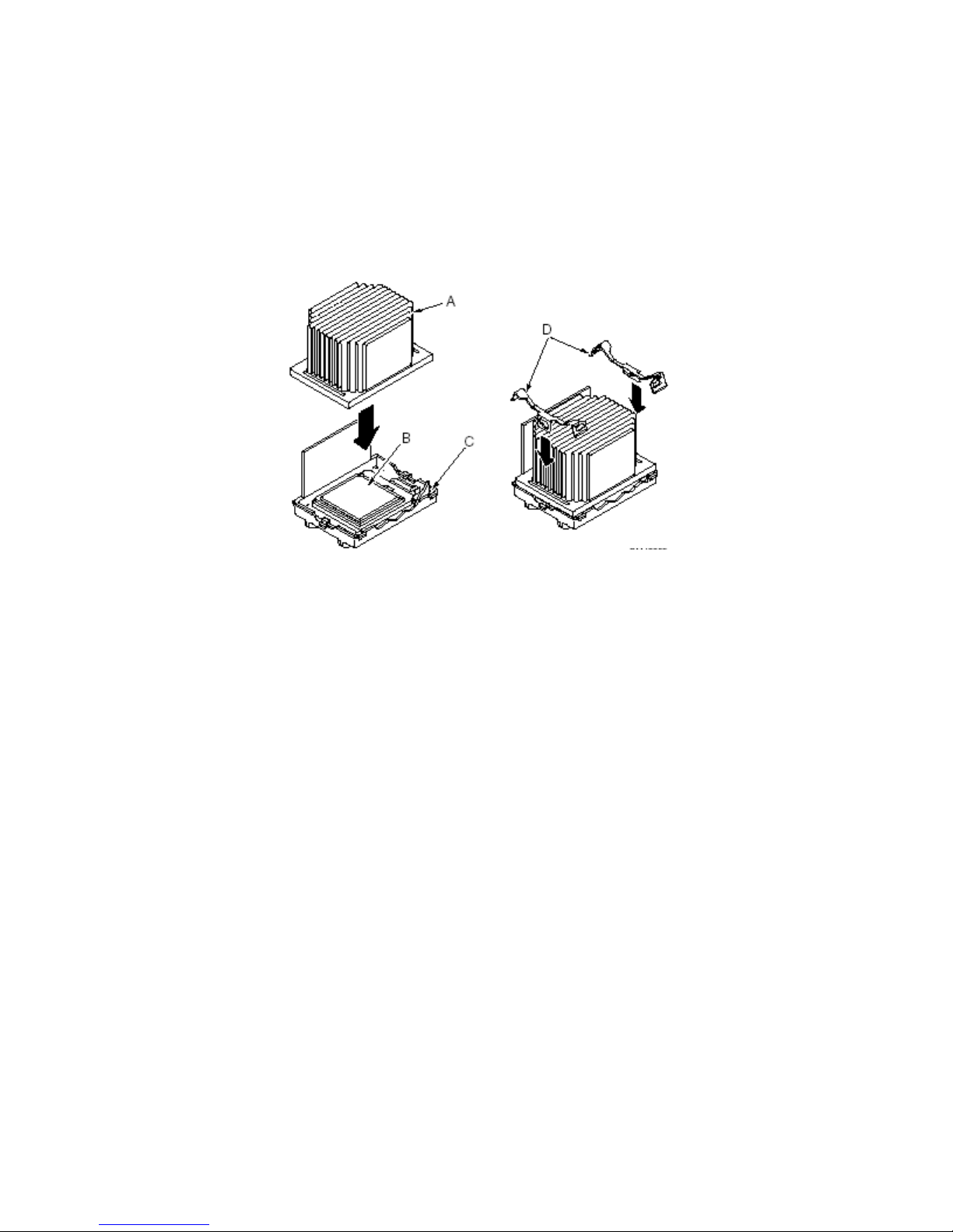
6. Following the instructions packaged with the applicator, apply thermal grease to the processor.
7. Insert the heat sink into the air baffle and place it on top of the processor (Figure 17, A).
8. Install both heat sink clips as follows:
a. Place the heat sink clip on the center tab of the retention module and slide the clip to the
right to engage the center tab.
b. Snap one end of the clip down over the corresponding tab on the retention module.
c. Snap the remaining end of the clip down over the corresponding tab.
A Heat sink C Retention module
B Socket and processor D Heat sink retention clips
Figure 17. Installing the Heat Sink
44
Page 45
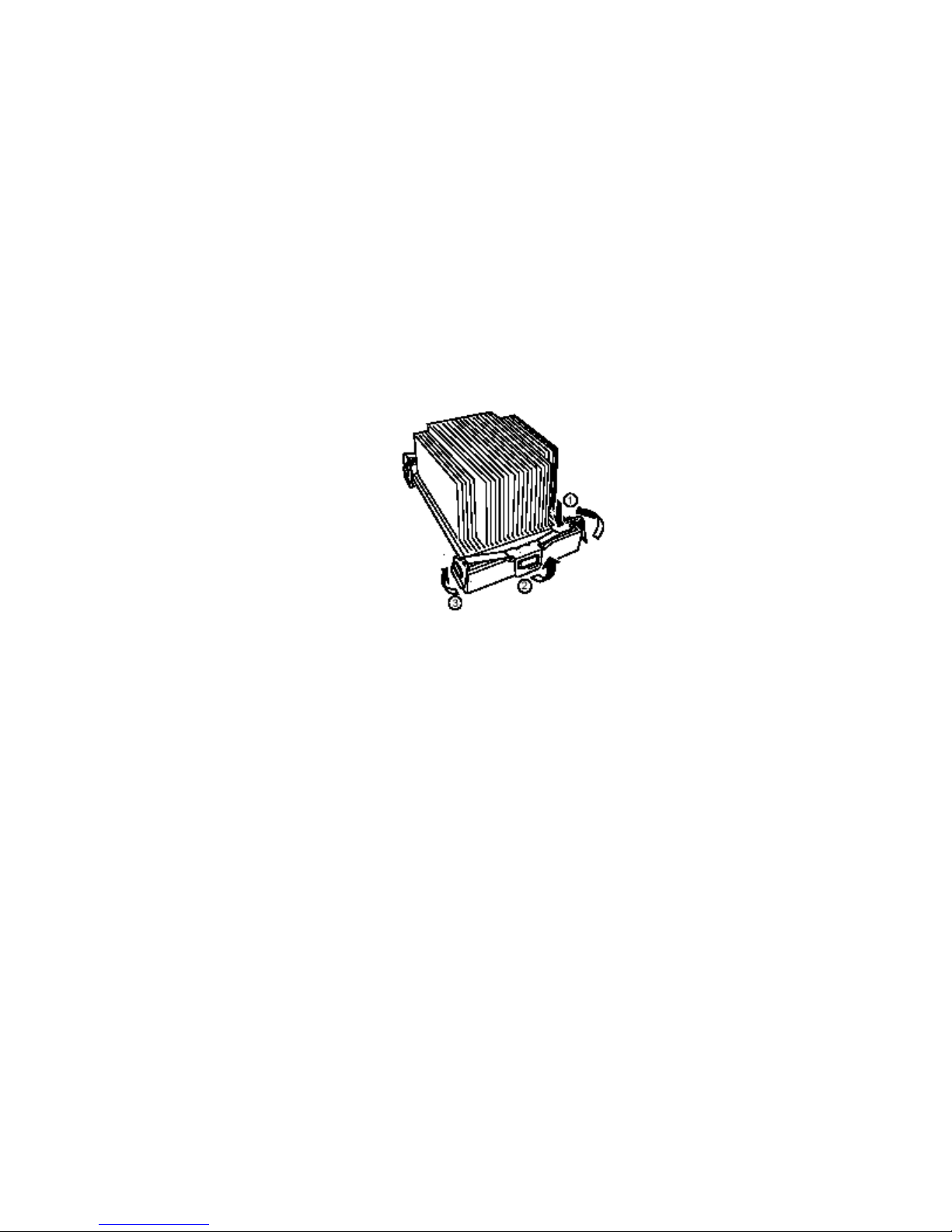
Removing Processors
To remove processors:
1. Observe the safety and ESD precautions at the beginning of this document.
2. Remove both heat sink clips as follows:
a. Press down the tab of the clip until the end of clip is free. (Figure 18).
b. Slide the clip to the left to disengage it from the center tab on the retention module and
remove the clip.
c. release the other end of the clip.
3. Lift the heat sink straight out of the retention module.
4. Raise the locking bar on the socket.
5. Remove the processor from the socket.
Figure 18. Removing a Processor
Installing and Removing Components 45
Page 46

Memory
This section includes instructions for removing and installing DIMMs on the memory board. For a
list of supported memory, call your service representative.
Installing DIMMs
CAUTION
Use extreme care when installing a DIMM. Applying too much pressure can
damage the socket. Keyed DIMMs insert only one way.
NOTE
✏
Load the DIMMs in the following order (Figure 19).
1. Bank 1: DIMMs #1, 2, 3, and 4
2. Bank 2: DIMMs #5, 6, 7, and 8
3. Bank 3: DIMMs #9, 10, 11, and 12
Always fill banks completely. Partially filled banks are ignored by the system.
Use only approved DIMMs listed on the NEC customer support Web site:
IMPORTANT: Install four additional DIMMs for each group because the server uses interleaved
memory. If DIMMs of different specifications* are installed in a group, the server does not operate
normally.
* DIMM specification is shown on the label attached to the DIMM as follows:
Example: Frequency of 200 MHz, buffered, capacity of 128 MB, raw address of 12 bits, column
address of 10 bits, and
200 / B / 128 / R12 C10 S
Single side
Column address
Raw address
Capacity
Buffered
Frequency
single side
46
Page 47

To install DIMMs:
1. Remove the memory board (page 33), and place the board component-side up on a
nonconductive, static-free surface.
2. Holding the DIMM only by its edges, remove it from its antistatic package.
Figure 19. Installing Memory
3. Open the plastic ejector levers at each end of the DIMM socket on the memory board
(Figure 19, A).
4. Orient the DIMM so that the notch in the bottom edge of the DIMM aligns with the keyed socket
on the memory board.
5. Insert the bottom edge of the DIMM into the socket and press down firmly on the DIMM until it
seats correctly. The plastic ejector levers should snap into place when the DIMM is seated.
6. Make sure that the plastic ejector levers on the socket ends are fully closed.
7. Reinstall the memory board (page 34).
Installing and Removing Components 47
Page 48

Removing DIMMs
1. Remove the memory board (page 33). Place the board component-side up on a nonconductive,
static-free surface.
2. Locate the DIMM you want to remove and gently push down on the plastic ejector levers
(Figure 20, A) to eject the DIMM from its socket.
3. Hold the DIMM only by its edges, being careful not to touch its components or gold edge
connectors. Carefully lift it away from the socket and store it in an antistatic package.
Figure 20. Removing DIMMs
48
Page 49
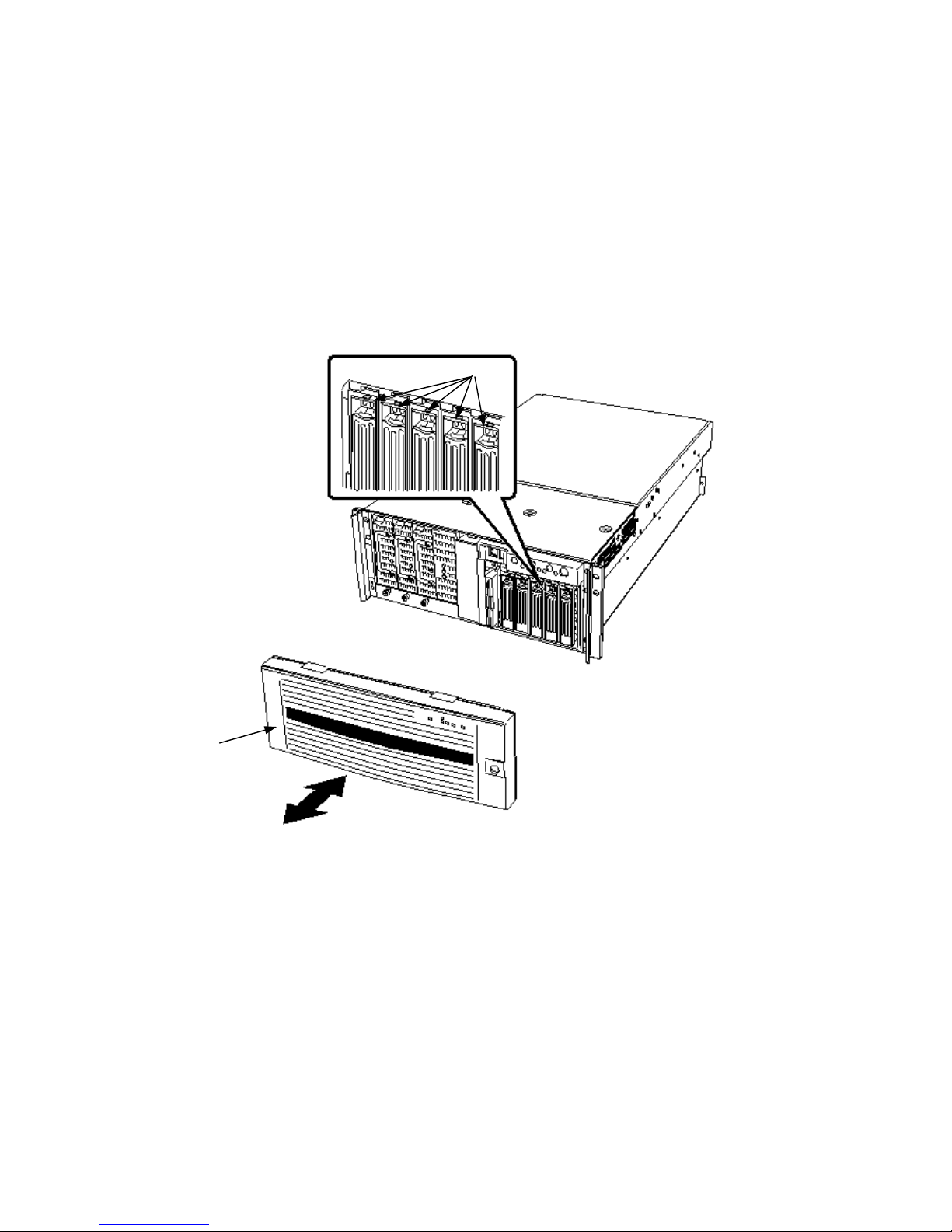
Hot-Swap SCSI Drives
Hot-swap drives are installed in carriers that fit into the hot-swap drive bay. This section describes
the LED status indicators for the drive bays and gives instructions for using the drive carriers to
install and remove drives.
Checking a Hot-Swap SCSI Drive Status Indicator
Each hot-swap SCSI drive slot has an LED that indicates drive status (Figure 21). To view the
LEDs, open the front bezel.
A Bezel B LED status indicators
Figure 21. Hot-Swap SCSI Drive Bay and Status Indicators
Installing and Removing Components 49
Page 50
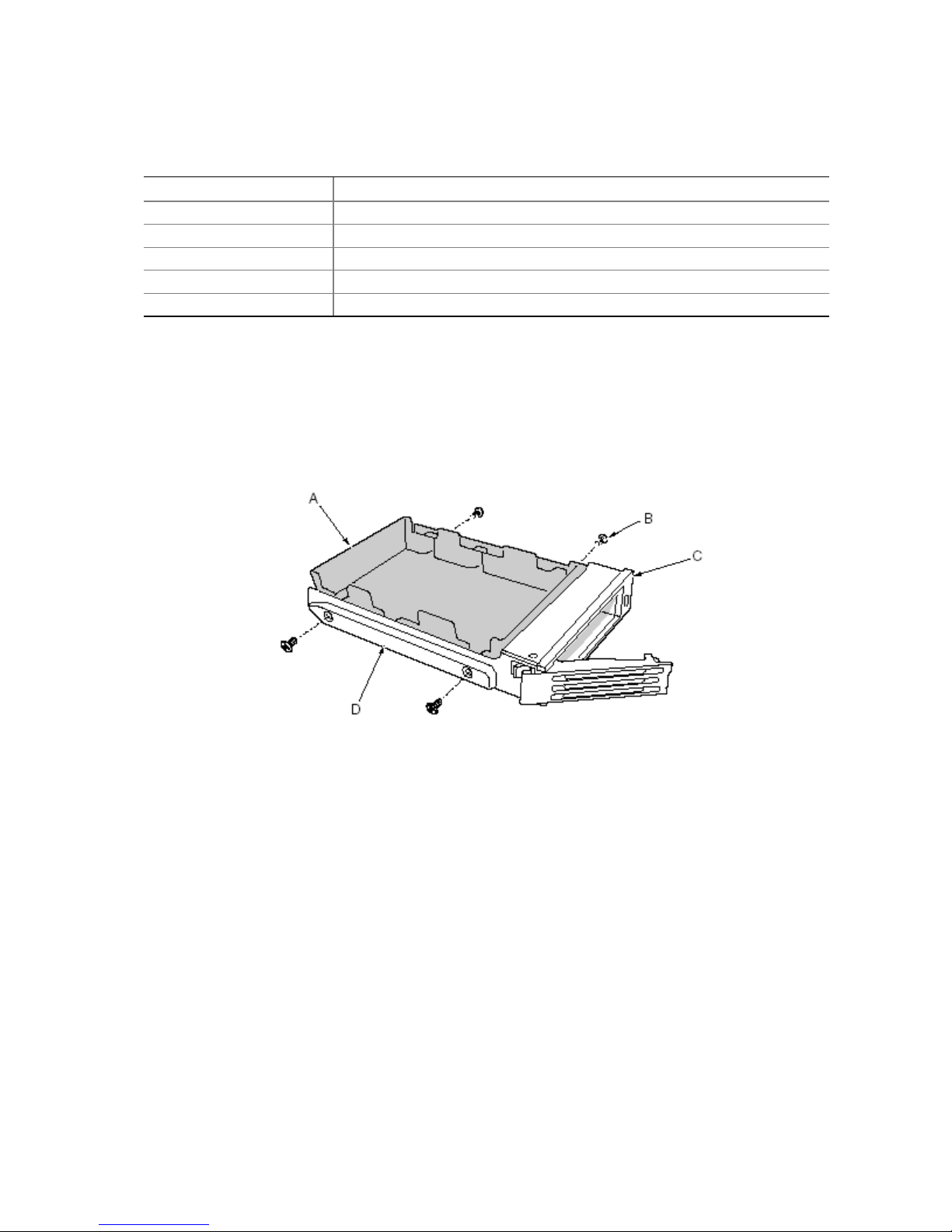
Table 5 lists the LED states and the drive status indicated by each state.
Table 5. LED States for Hot-Swap SCSI Drive Status
LED State Status
Solid green The hard drive is present and powered on.
Flashing green The hard drive is active.
Solid yellow There is an asserted fault status on the hard drive.
Flashing yellow A rebuild of the hard drive is in progress.
Off The hard drive is not powered on.
Installing a Hot-Swap Drive in a Carrier
Before you can install a drive in the hot-swap drive bay, you must install the drive into a drive
carrier. To install a hot-swap drive in a carrier:
1. If the plastic air baffle is installed in the carrier, remove the four screws that attach the air baffle
to the carrier. Save the air baffle in case you later remove a drive.
Figure 22. Removing a Plastic Air Baffle from a Carrier
2. Remove the hard drive from its wrapper and place it on an antistatic surface.
3. Record the new drive model and serial number in your equipment log.
50
A Air Baffle C Carrier
B Screw D Plastic rail
Page 51

4. Place the drive in the carrier with the component side down.
5. Using the four screws removed earlier, attach the drive to the carrier.
A SCA Connector D Plastic Rail
B Drive E Screw
C Carrier
Figure 23. Installing a SCSI Hard Disk Drive in a Carrier
Removing a Hot-swap Drive from a Carrier
To remove a hot-swap drive from a carrier:
1. Remove the carrier and drive from the drive bay.
2. Remove the four screws that secure the drive to the carrier.
3. Place the drive on an antistatic surface.
4. If you are going to reinstall the carrier without a drive, you must first replace the air baffle in the
carrier (Figure 22).
Installing and Removing Components 51
Page 52
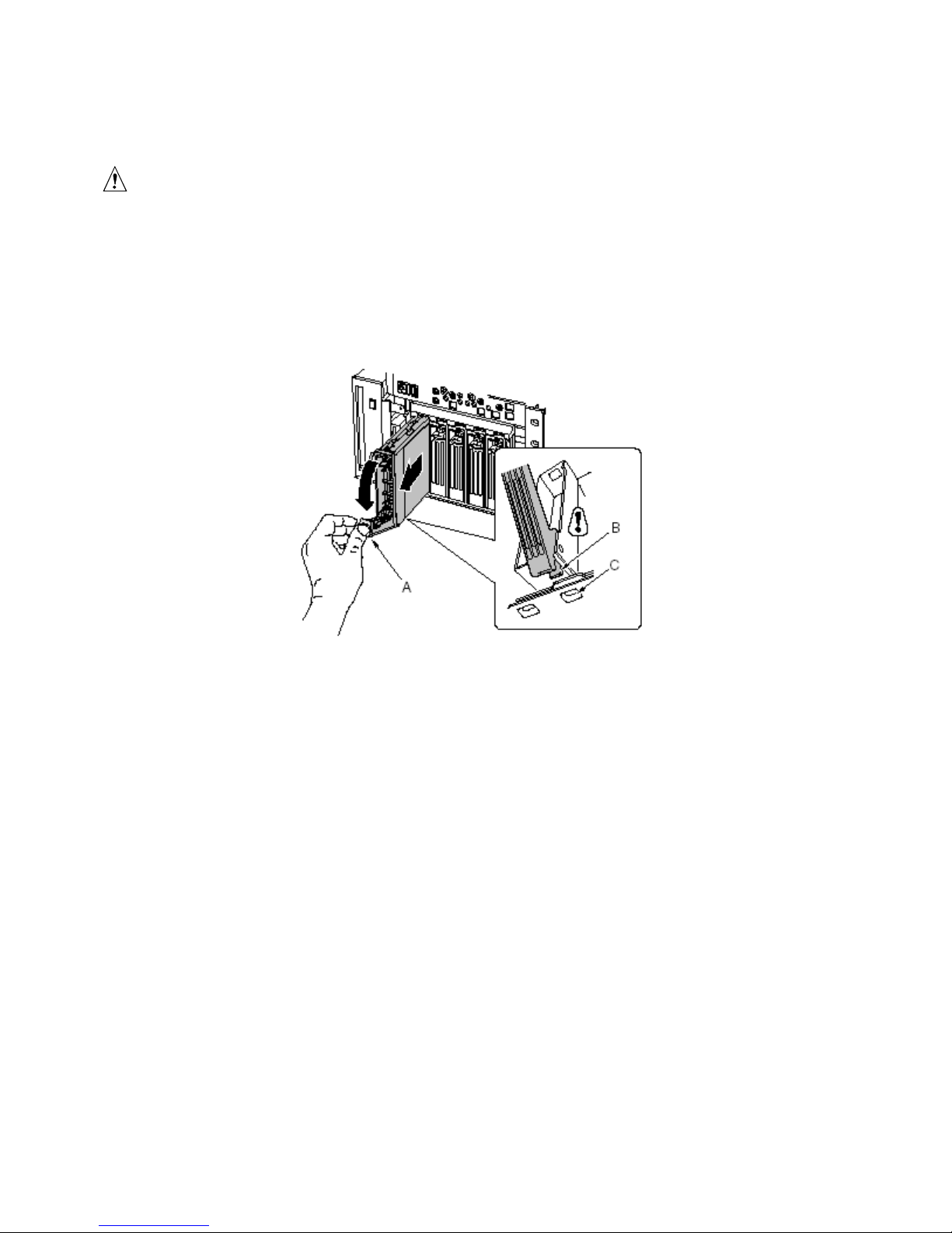
Removing and Installing Hot-Swap Disk Drives
CAUTION
Do not leave any drive slots without a drive or air baffle installed in the
carrier. An empty carrier installed in a drive slot reduces cooling efficiency
and can affect performance or cause damage due to overheating.
To replace a hot-swap disk drive:
1. Depress the green clip at the end of the plastic carrier handle. Pull the handle out to disengage
the carrier handle latch from the locking slot at the top of the drive bay (Figure 24, B and C).
A Handle C Locking slot
B Latch
Figure 24. Removing a Drive Carrier
2. Carefully pull on the carrier handle and slide the carrier out of the bay.
52
Page 53

3. Install a new drive into the carrier (page 50).
4. Hold the carrier handle in the fully open position and slide the carrier into the desired bay.
5. Push the carrier into the drive bay until the carrier handle latch engages the locking slot in the
edge of the drive bay (Figure 25, C).
6. Push the handle closed until it clicks into position.
A Handle C Locking slot
B Latch
Figure 25. Installing a Drive Carrier
Installing and Removing Components 53
Page 54

DC Power Supplies
The power supply bay accommodates up to three power supply modules. The bay contains a power
distribution board (PDB) that manages the delivery of power from the power supply modules.
Checking the Power Status LEDs
To view the power supply status LEDs (Figure 26), remove the bezel, as described on page 28.
A Power LEDs (PWR) C Redundant AC LED (AC_R)
B Standby LEDs (SB1 and SB2)
Figure 26. Power and Standby LEDs
Table 6 lists the LED states and the power supply status indicated by each state.
Table 6. LED Power Supply Status Indicators
Power LED State Status
On AC power is applied and the power module is functioning properly.
Off Module is disabled.
Module is overstressed.
Module replacement required.
Standby LEDs State Status
On AC power is applied to corresponding power module, SB1 (left) or SB2
(right).
Redundant AC LED State Status
On Redundant (center) module is installed and power subsystem is operating in
redundant AC mode.
Off Power subsystem is not operating in redundant AC mode.
54
Page 55

NOTE
✏
If all power supply modules are functioning and all power cables from the
power distribution board are properly connected to the baseboard and other
components, but the server still won’t power on, replace the power supply bay
(page 72).
Removing a Power Supply Module
To remove a power supply module:
1. Remove the bezel (page 28).
A Power supply module C Locking tab
B Captive screw D Handle
Figure 27. Removing a Power Supply Module
2. Loosen the captive screw that retains the power supply module.
CAUTION
To avoid damaging the module, do not tilt or twist the power supply module
as you pull it from the power supply bay. The module disengaging from its
connector causes the initial resistance you will feel. Use even, steady force to
remove the supply.
3. While pressing down on the locking tab, grasp the handle and carefully pull the module out of
the power supply bay.
4. If you are not going to install a replacement module, you must install a filler panel in the
vacant slot.
5. Install the bezel.
Installing and Removing Components 55
Page 56

Installing a Power Supply Module
To install a power supply module:
1. Remove the bezel (page 28).
2. If present, remove the filler panel from the vacant slot.
3. Slide the power supply module into the vacant slot until you feel resistance.
CAUTION
The module engaging its connector causes the resistance. To avoid damaging
the module, do not tilt or twist the power supply module as you push it into the
connector.
4. Push the module into the bay until the locking tab snaps into place.
The green LED on the power supply module should be illuminated.
5. Tighten the captive screw that retains the power supply module.
6. Install the bezel.
56
Page 57

PCI Add-In Boards
The EXPRESS5800/140Rc-4 server supports four hot-plug PCI add-in boards and four non-hot-plug
PCI add-in boards.
A Four hot-plug 64-Bit, 100-MHz
PCI-X add-in board slots
B Two non-hot-plug 64-Bit, 100-MHz
PCI-X add-in board slots
Figure 28. PCI Add-In Board Locations
C Two non-hot-plug 32-Bit, 33-MHz
PCI add-in board slots
CAUTION
Be sure any empty expansion slots have a slot cover installed. An open
expansion slot reduces the cooling and EMI integrity of the server and can
affect performance and cause damage due to overheating.
Operating System Support for Hot-Plug Add-In Boards
Only Windows 2000 supports hot-plugging PCI add-in boards(Windows NT4.0 does not support)
. Operating system support is provided by a driver that you must install when setting up your server.
Hot-plug drivers are available on the NEC EXPRESSBUILDER CD in the Drivers directory. The
driver files on the CD include information on installing and using the hot-plug software.
Installing and Removing Components 57
Page 58

Without a driver, the operating system does not support hot-plug installation and removal of PCI
add-in boards. In that case, you must treat all eight PCI slots as non-hot-plug slots and follow the
instructions on pages 61 and 62 for installing and removing all PCI add-in boards.
Checking the Status Indicators for a Hot-Plug Add-In Board
A bank of LED indicators on the back panel of the electronics bay indicates the status of the hot-plug
PCI add-in boards (Figure 29).
A Status LED indicators
Figure 29. Status Indicators for Hot-Plug PCI Add-In Boards
Table 7 lists the LED states and the hot-plug PCI status indicated by each state.
Table 7. LED Hot-Plug PCI Status Indicators
Power LED State Status
Green Power to slot
Amber Fault on slot(lighting)
Available for hot remove(flashing)
Not lit No power to slot
58
Page 59

Installing a Hot-Plug PCI Add-In Board
To install a hot-plug PCI add-in board:
1. Remove the rear access cover (page 29).
2. If the LED for the slot indicates that power to the slot is on, turn it off by using the PCI hot-plug
application software on your system (see “Operating System Support for Hot-Plug Add-In
Boards” on page 57).
The LED adjacent to the slot should now be off.
3. Open the latches on the front and rear retention mechanisms (Figure 30, A and B).
4. If necessary, remove and save the expansion slot cover.
5. Prepare the new PCI board for installation:
a. Remove the add-in board from its protective wrapper. Be careful not to touch the
components or gold edge connectors. Place the add-in board with the component side up on
an antistatic surface.
b. Record the serial number of the add-in board in your equipment log.
c. Set jumpers or switches according to the manufacturer’s instructions.
Figure 30. Installing a Hot-Plug PCI Add-In Board
6. On the edge opposite the connectors, grasp the board by both corners. Orient the board to the
vacant hot-plug slot so that the metal retention bracket is toward the rear of the chassis.
7. Insert the board into the front and rear retention mechanisms. Carefully push down on the board
until it engages and fully seats in the slot connector.
Installing and Removing Components 59
A Latch, rear retention mechanism
B Latch, front retention mechanism
Page 60

8. Close the front and rear latches.
9. Install the rear access cover.
10. Turn on power to the add-in board using the PCI hot-plug application software on your system.
Removing a Hot-Plug PCI Add-In Board
To remove a hot-plug PCI add-in board:
1. Remove the rear access cover (page 29).
If the LED for the slot indicates that power to the slot is on, turn it off by using the PCI hot-plug
application software on your system (Refer to the “EXPRESS BUILDER CD 3.091 A-N” (36301632-000)
The LED adjacent to the slot should now be flashing.
2. Disconnect any cables attached to the board you are removing.
Figure 31. Removing a Hot-Plug PCI Add-In Board
3. Release the latches on the front and rear retention mechanisms (Figure 31, A and B).
4. Grasp the board at both corners, pull it out of the slot connector, and carefully slide it out of the
retention mechanisms. Store the board in an antistatic protective wrapper.
5. If you are not reinstalling a board in the same slot, install an expansion slot cover and install the
rear access cover. If you are installing a new board, follow the instructions on page 59.
60
A Latch, rear retention mechanism
B Latch, front retention mechanism
Page 61

Installing a PCI Add-In Board in a Non-Hot-Plug Slot
CAUTION
The PCI add-in board slots located under the system board access cover are
not hot-plug slots.
To install a PCI add-in board in a non-hot-plug slot:
1. Disconnect the AC power cords from the power source or wall outlets.
2. Turn off all peripheral devices connected to the server system.
3. Remove the rear access cover (page 29) and the system board access cover (page 32).
4. If necessary, remove and save the expansion slot cover.
5. Prepare the new PCI board for installation:
a. Remove the add-in board from its protective wrapper. Be careful to not
touch the components or gold edge connectors. Place the board with the
component side up on an antistatic surface.
b. Record the serial number of the new add-in board in your equipment log.
c. Set jumpers or switches according to the manufacturer instructions.
6. Open the latches on the front and rear retention mechanisms (Figure 32, A and B).
7. On the edge opposite the connectors, grasp the board by both corners. Orient the board to the
vacant slot so that the metal retention bracket is toward the rear of the chassis.
Figure 32. Installing and Removing a Non-Hot-Plug PCI Add-In Board
Installing and Removing Components 61
A Latch, rear retention mechanism
B Latch, front retention mechanism
Page 62

8. Insert the board into the front and rear retention mechanisms. Carefully push down on the board
until it engages and fully seats in the slot connector.
9. Close the front and rear latches.
10. Install the system board access cover and the rear access cover.
11. Turn on any peripheral devices connected to the system.
12. Connect the power cord and turn on power to the server.
Removing a PCI Add-In Board from a Non-Hot-Plug Slot
CAUTION
The PCI add-in board slots located under the system board access cover are
not hot-plug slots.
To remove a PCI add-in board from a non-hot-plug slot:
1. Disconnect the AC power cords from the power source or wall outlets.
2. Turn off all peripheral devices connected to the server system.
3. Remove the rear access cover (page 29) and the system board access cover (page 32).
4. Release the latches on the front and rear retention mechanisms.
5. Grasp the board by the top edge or corners, carefully pull it out of the connector, and slide it free
of the retention bracket.
6. If you are installing a new board, follow the instructions on page 61. If you are not installing
another PCI add-in board, continue with the next step below.
7. Install a slot cover over the vacant slot in the back panel.
8. Install the system board access cover and the rear access cover.
9. Turn on any peripheral devices connected to the system.
10. Connect the power cord and turn on power to the server.
62
Page 63

Cooling System Fans
The server accommodates six hot-swap fans.
CAUTION
Don’t remove a fan while the server is powered on unless you have a
replacement unit available. Once you remove an individual fan from the
system, replace it within five minutes. Vacant spaces alter airflow patterns in
the server system and can cause overheating and damage to system
components.
Checking a Fan Status Indicator
A fan status indicator is adjacent to each fan module (Figure 33). The indicators are triangular in
shape and point to their respective modules. When a fan is not functioning normally, the indicator is
illuminated; otherwise, the indicator is not illuminated. A fan failure is also indicated by the general
system fault LED located on the front panel.
Installing and Removing Components 63
A Fan status indicator
Figure 33. Fan Status Indicator
Page 64
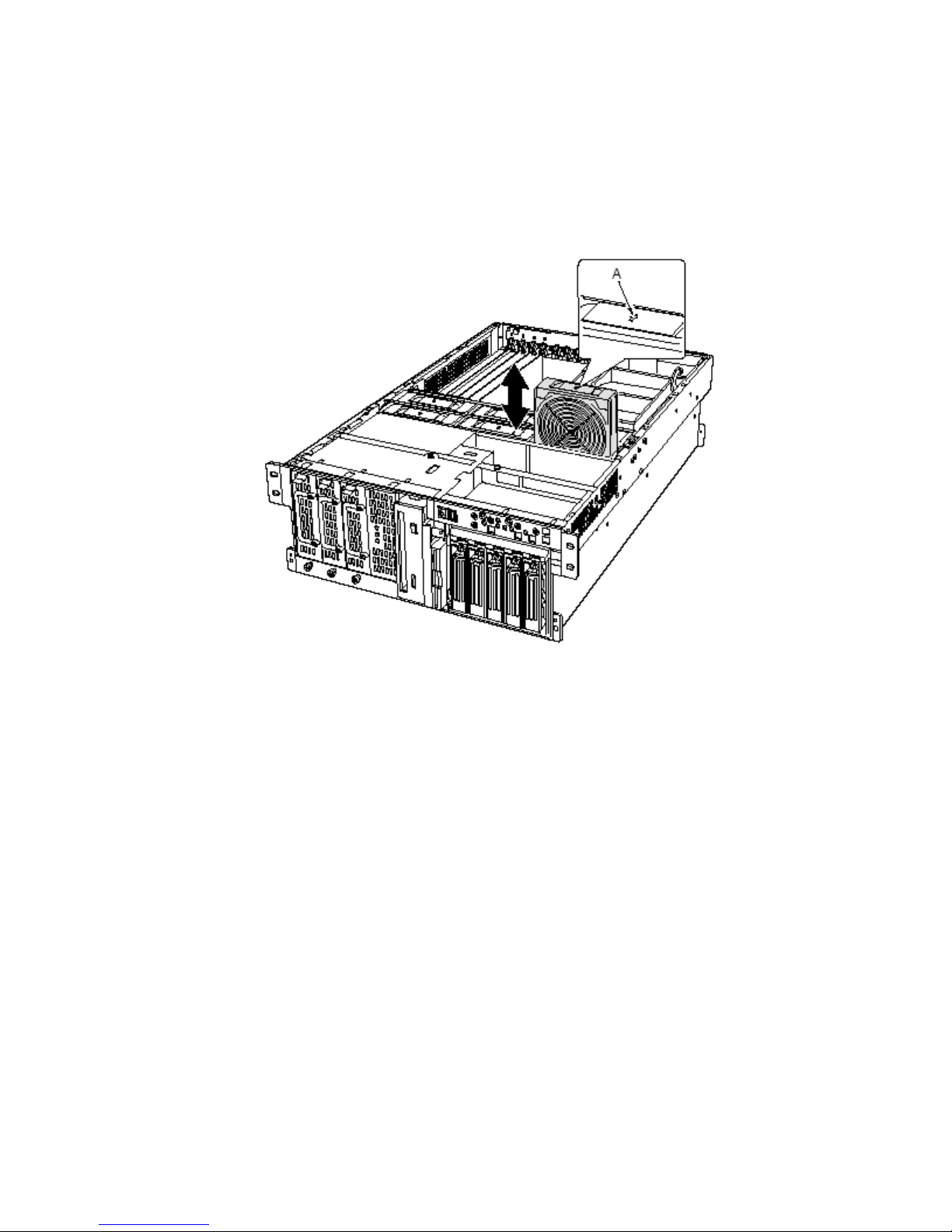
Removing a Fan Module
To remove a fan:
1. Remove the rear access cover (page 29).
2. Grasp the fan module and pull it straight out of the fan assembly.
A Airflow direction indicator
Figure 34. Removing and Installing a Fan Module
64
Page 65

Installing a Fan Module
✏ NOTE
If you are replacing a failed fan, wait for the fan status indicator to turn off.
Backup Battery
Generally, this will take less than ten seconds.
To install a fan, follow these instructions:
1. Remove the rear access cover (page 29).
2. Place the fan module into the empty slot of the fan assembly. Be sure that the airflow direction
arrow is pointing toward the rear of the chassis (Figure 34, A).
3. Check the fan status indicator for the replacement fan. If the installation was successful, the
indicator will not be lit.
4. Install the rear access cover.
The lithium battery on the baseboard powers the real-time clock (RTC) for up to 10 years in the
absence of power. When the battery starts to weaken, it loses voltage, and the server settings stored
in CMOS RAM in the RTC (for example, the date and time) might be incorrect.
For a list of approved replacement batteries, contact your customer service representative or dealer.
WARNING!
Danger of explosion if battery is incorrectly replaced. Replace with only the
same or equivalent type recommended by the manufacturer. Dispose of used
batteries according to the manufacturer’s instructions.
ADVARSEL!
Lithiumbatteri - Eksplosionsfare ved fejlagtig håndtering. Udskiftning må kun
ske med batteri af samme fabrikat og type. Levér det brugte batteri tilbage til
leverandøren.
ADVARSEL!
Lithiumbatteri - Eksplosjonsfare. Ved utskifting benyttes kun batteri som
anbefalt av apparatfabrikanten. Brukt batteri returneres apparatleverandøren.
VARNING!
Explosionsfara vid felaktigt batteribyte. Använd samma batterityp eller en
ekvivalent typ som rekommenderas av apparattillverkaren. Kassera använt
batteri enligt fabrikantens instruktion.
Installing and Removing Components 65
Page 66
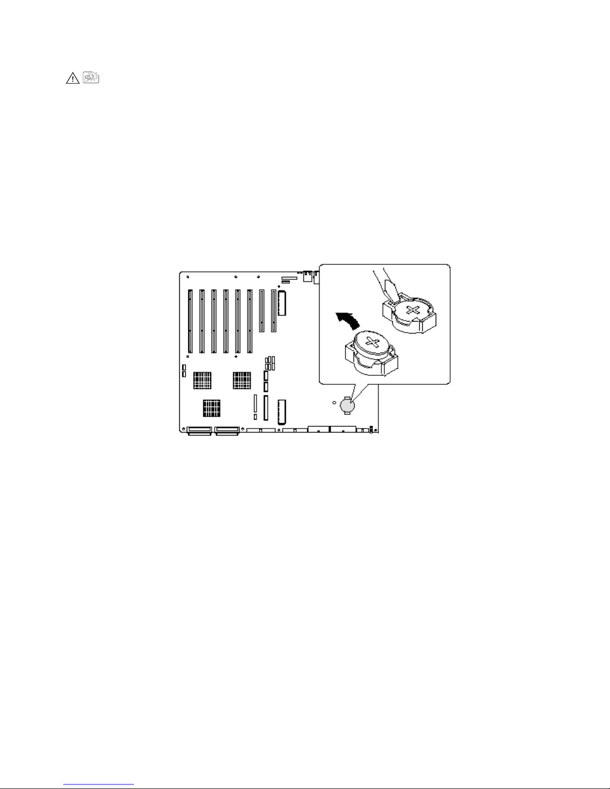
VAROITUS!
Paristo voi räjähtää, jos se on virheellisesti asennettu. Vaihda paristo
ainoastaan laitevalmistajan suosittelemaan tyyppiin. Hävitä käytetty paristo
valmistajan ohjeiden mukaisesti.
To replace the battery:
1. Before proceeding, record your custom BIOS settings.
2. Disconnect the AC power cords from the power source or wall outlets.
3. Turn off all peripheral devices connected to the server system.
4. Remove the rear access cover (page 29), the system board access cover (page 32), the memory
board (page 33), the air baffle (page 35), and the processor board (page 37).
5. Slide the battery in the direction shown in Figure 35, allowing the battery to pop up.
6. Remove the battery from its socket.
Figure 35. Replacing the Backup Battery
7. Dispose of the battery according to local ordinance.
8. Remove the new lithium battery from its package.
9. Being careful to observe the correct polarity, lay the battery in the socket, inserting one edge of
the battery under the large corner tabs.
10. Push the battery down until it locks into the socket.
11. Install the processor board, air baffle, memory board, system board access cover, and the rear
access cover.
12. Run BIOS Setup to restore the configuration settings to the RTC.
13. Restore your custom BIOS settings.
66
Page 67
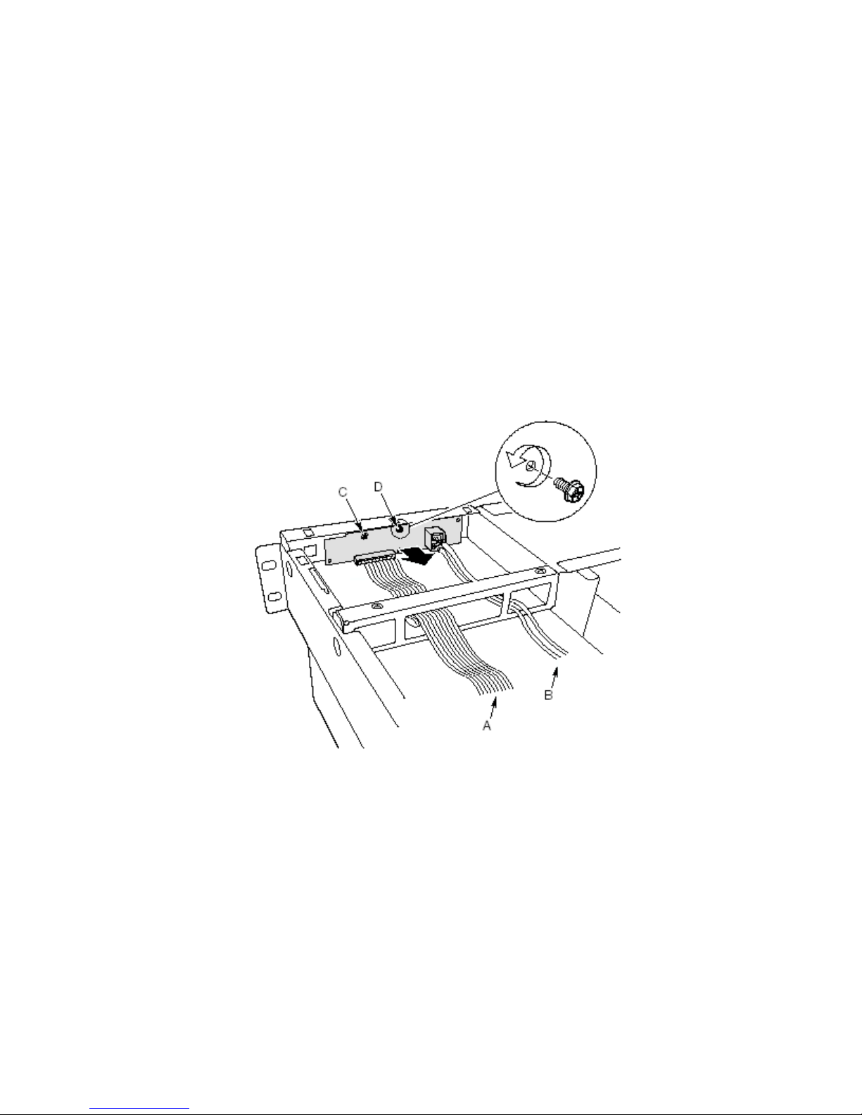
Front Panel Board
For a description of the features on the front panel board, see page 106.
To replace the front panel board:
1. Turn off power to the server and unplug the AC power cords from the power source.
2. Remove the bezel and the front access cover (pages 28 and 30).
3. Disconnect the cables from front panel board: the front panel board ribbon cable, the USB port
cable, and the serial port cable.
One end of the front panel board is inserted into a slot in the chassis and the other end is secured
with a screw and a snap-top standoff.
4. Remove the screw that secures the front panel board to the chassis.
5. Grasp the end of the board closest to the side of the chassis and pull to disengage the board from
the standoff.
6. Rotate the free end of the board out until the USB and serial ports clear the chassis, disengage
the other end of the board from the slot in the chassis, and lift the board clear of the chassis.
A Front panel board cable C Snap-top standoff
B USB and serial port cables D Retaining screw
7. Position the end of the replacement board in the slot in the chassis and rotate the free end of the
board into position, snapping it down over the standoff.
8. Install the retaining screw.
9. Connect the front panel board ribbon cable to the front panel board.
10. Connect the USB and serial port cables to the front panel board.
11. Install the front access cover and the bezel.
Installing and Removing Components 67
Figure 36. Replacing the Front Panel Board
Page 68

Peripheral Drives
This section provides information and instructions for installing and removing devices from the
5.25-inch peripheral bay and the media bay.
Preliminary Considerations
CAUTION
You should not install hard drives in the 5.25-inch peripheral drive bay for two
reasons:
• The drives cannot be properly cooled in this location.
• The total EMI from the server might exceed allowable limits, because the hard drive
generates additional EMI.
To avoid damage to a 5.25-inch peripheral device, ensure the EMI gasket
provided in the device bay does not bridge any open circuits on the exposed
peripheral device.
Drive Cables
This section summarizes drive cable requirements and constraints. The number of peripheral drives
you can install depends on:
• The number supported by the bus
• The number of drive bays available
• The height of drives in the bays (1-inch or 1.6-inch high)
• The combination of SCSI and IDE devices
IDE Requirements
The server includes an IDE controller and a cable that supports two devices. One of the two
connectors on the cable is already used for the CD-ROM drive. The CD-ROM device is configured
for Cable Select (CS) and is at the end of the cable; this defines the CD-ROM as the IDE master. If
you install a second IDE device, and it is jumpered for Cable Select, connect the device on the
middle IDE connector to configure the device as IDE slave, or at the end of the cable to configure the
device for IDE master.
SCSI Requirements
The server includes a two-channel SCSI controller. One channel is used for the hot-swap drive bay.
You may use the second channel for SCSI devices in the peripheral bay. SCSI cabling and
connections must meet the SCSI bus specification. Otherwise, the bus might be unreliable and data
might become corrupted or devices might not work properly.
EMC Compliance of 5.25-inch Removable Media Device Bays
Integration of the 5.25-inch peripheral drive bay can affect EMC compliance and is a regulated
activity. Except as noted here, any changes to the bay configuration could result in non-compliance
with EMC regulations in your area.
68
Page 69

Installing a 5.25-inch Peripheral Drive
To install a peripheral drive:
1. Turn off power to the server and unplug the AC power cords from the power source.
2. Remove the bezel and the front access cover (pages 28 and 30).
3. Remove the fan assembly (page 74).
4. If the drive bay is covered by a metal EMI shield, insert your finger in the large hole in one end
of the shield and pull the shield from the chassis. Save the shield.
5. If the drive bay has an existing drive installed, remove the drive (page 70) and remove the slide
rails attached to the sides of the drive. Save the rails and screws.
6. Remove the new drive from its protective wrapper and place it on an antistatic surface.
7. Record the new drive model and serial numbers in your equipment log.
8. Set any jumpers or switches on the new drive according to the drive manufacturer’s instructions.
9. Attach a slide rail to each side of the drive using two mounting screws.
Figure 37. Removing and Installing a 5.25-inch Peripheral Drive
10. Position the drive so the plastic slide rails engage the guide rails in the peripheral bay. Push the
drive into the bay until the slide rails lock in place.
11. Connect the signal and power cables to the drive. You can insert the keyed connectors only one
way.
12. Install the fan assembly, the front access cover, and the bezel.
Installing and Removing Components 69
A Data cable C Slide rails
B Power cable
Page 70

Removing a 5.25-inch Peripheral Drive
To remove a peripheral drive:
1. Turn off power to the server and unplug the AC power cords from the power source.
2. Remove the bezel and the front access cover (pages 28 and 30).
3. Remove the fan assembly (page 74).
4. Disconnect the power and data cables from the back of the drive.
5. Facing the front of the drive, press in on the two black plastic tabs (Figure 37, C), one at each
side of the drive, to release the drive from the drive bay.
6. Carefully slide the drive out of the bay and place it on an antistatic surface.
7. Remove the four screws that secure the two slide rails to the drive. Save the screws and
slide rails.
8. If you are installing a replacement device, skip to “Installing a 5.25-inch Peripheral Drive,”
step 6, on page 69 to install that device.
9. Install the fan assembly, front access cover, and bezel.
NOTE
✏
If you leave the drive bay empty, install a metal EMI shield on the bay for proper
cooling and airflow. Installing a drive in the bay or covering the bay with a filler
panel or EMI shield protects the System EMI integrity and cooling. When you
install a drive, save the filler panel and EMI shield to reinstall if you should later
remove the drive and not reinstall one in the same bay.
Removing a Device from the Media Bay
To remove a device from the media bay:
1. Turn off power to the server and unplug the AC power cords from the power source.
2. Remove the bezel and the front access cover from the chassis (pages 28 and 30).
3. Remove the fan assembly (page 74).
4. Disconnect the power and data cables from the back of the device (Figure 38).
5. Remove and save the screw that attaches the device to the bay.
6. Slide the device out. If the device will be used again, place it in an antistatic protective wrapper.
7. Install the fan assembly, front access cover, and bezel.
8. Plug the AC power cords into the power source and turn on power to the server.
✏ NOTE
If you leave the device bay empty, install a metal EMI shield on the bay for proper
cooling and airflow. Installing devices in the bays or covering the bays with filler
panels or EMI shields protects the System EMI integrity and cooling. When you
install a device, save the filler panel or EMI shield to reinstall if you should later
remove the device and not reinstall one in the same bay.
70
Page 71

A Power cables C Screw
B Data cables
Figure 38. Removing a Device from the Media Bay
Installing a Device in the Media Bay
To install a device in the media bay:
1. Turn off power to the server and unplug the AC power cords from the power source.
2. Remove the bezel and the front access cover (pages 28 and 30).
3. Remove the fan assembly (page 74).
4. Slide the drive into the bay. Install the screw that attaches the drive to the bay (Figure 38, C,
above).
5. Connect the power and signal cables to the drive (Figure 38, A and B, above).
6. Install the fan assembly, front access cover, and bezel.
7. Run BIOS Setup to specify that the device is installed in the system.
Installing and Removing Components 71
Page 72

Power Supply Bay
Replacing the Power Supply Bay
To replace the power supply bay:
1. Turn off power to the server and unplug the AC power cords from the power source.
2. Remove the bezel, the front access cover, and the rear access cover (pages 28, 29, and 30).
3. Remove all power supply modules (optional).
4. Remove the fan assembly (page 74).
5. Label and disconnect all power and data cables attached to the hot-swap drive bay and the
peripheral bay devices. Lift the cables out of the bottom of the fan bay.
6. At the baseboard, label and disconnect the power cables that go to the power supply bay.
7. Remove the front chassis bracket:
a. Disconnect the cables from the front panel board.
b. Remove the four screws attaching the bracket to the chassis (Figure 39, G).
c. Slide the bracket toward the front of the chassis.
d. Lift the bracket up and clear of the chassis.
A Locking tab E Power LED, power supply module
B Standby LEDs F Handle, power supply module
C Retaining screw, power supply bay G
D Captive screw, power supply module
8. Remove the electronics bay from the main chassis.
9. Remove the AC power cable from the chassis retention clips.
72
Screw, front chassis bracket (two each side
of chassis)
Figure 39. Power Supply Bay
Page 73

10. Loosen the captive screw retaining the power supply bay, slide the bay forward to free the tabs at
the rear of the bay, and lift the power supply bay out of the chassis.
11. Position the replacement power supply bay in the chassis so that the chassis tab slips into the slot
in the bottom of the bay to the rear of the captive screw.
12. Slide the bay to the rear and engage the two tabs on the bottom rear of the bay with the slots in
the chassis floor.
13. Tighten the captive screw that retains the bay.
14. Route the AC power cable, being sure to place it in all the chassis retention clips.
15. Install the electronics bay into the main chassis.
16. Install the front chassis bracket:
a. Align the tabs in the center of the underside of the bracket with slots in the top of the
peripheral bay and lower the bracket onto the chassis.
b. Slide the bracket toward the rear of the chassis until its front is flush with the chassis front.
c. Connect the cables to the front panel board.
d. Install the four screws attaching the bracket to the chassis.
17. At the baseboard, connect the power cables that go to the power supply bay.
18. Place all power and data cables back in the fan bay, being careful to route them as they were
originally.
19. Connect all power and data cables to the hot-swap drive bay and the peripheral bay devices.
20. Install the fan assembly.
21. Install all power supply modules.
22. Install the front access cover, the rear access cover, and the bezel.
23. Plug in the AC power and turn on power to the server.
24. Observe the power and standby LEDs and confirm that the power supply system is functioning
properly.
Installing and Removing Components 73
Page 74

Cooling System
Removing the Fan Assembly
To remove the fan assembly:
1. Turn off power to the server and unplug the AC power cord from the power source.
2. Remove the rear access cover (page 29).
3. Remove all fan modules from the fan assembly.
4. Remove the two screws that attach the fan assembly to the chassis.
A Screw
B Power and data connectors
Figure 40. Removing the Fan Assembly
5. Lift the fan assembly straight up until the cable connectors at the bottom are accessible.
6. Remove the cables and lift the fan assembly clear of the chassis.
74
Page 75

Installing the Fan Assembly
To install the fan assembly:
1. Position the fan assembly over the fan bay.
2. Attach the cables to the fan board at the bottom of the assembly.
3. Lower the fan assembly into the fan bay.
4. Install the two screws that attach the fan assembly to the chassis.
5. Install the fan modules into the fan assembly.
6. Install the rear access cover.
Replacing the Fan Board
To replace the fan board:
1. Remove the fan assembly (page 74).
A Screws (2) attaching fan base D Fan carrier board
B Upper fan assembly E Screws (4) attaching fan carrier board
C Fan assembly base
Figure 41. Replacing the Fan Board
2. Remove the two screws attaching the base to the fan assembly (Figure 41, A).
3. Rotate the base down and remove it from the fan assembly.
4. Remove the four screws securing the fan board to the base.
5. Lift up on the board to free it from the snap-top standoffs and remove the board.
6. Replace the board, snapping it over the two snap-top standoffs, and reinstall the four screws.
7. Reattach the base to the fan assembly and secure it with two screws.
8. Install the fan assembly in the fan bay.
Installing and Removing Components 75
Page 76

Hot-Swap Drive Bay
Removing the Hot-Swap Drive Bay
To remove the hot-swap drive bay:
1. Turn off power to the server and unplug the AC power cords from the power source.
2. Remove the bezel, the front access cover, and the rear access cover (pages 28, 29, and 30).
3. Remove all of the hot-swap drives (page 52).
4. Remove any devices in the media bay (page 70).
5. Disconnect the cables from the back of the drive bay.
6. While exerting forward pressure on the bay lip, use a flat-head screwdriver to unlock the right
hand black tab by pushing it toward the center of the bay. Maintaining forward pressure on the
bay helps keep the tab from returning to its locked position.
7. Repeat step 6 for the left hand locking tab.
8. With both tabs unlocked, pull the drive bay out of the chassis.
76
A Black locking tab (left hand side of
bay is a mirror image of right)
Figure 42. Removing a Hot-Swap Drive Bay
Page 77

Installing a Hot-Swap Drive Bay
To install a hot-swap drive bay:
1. Slide the drive bay into the chassis, pushing it firmly to the rear to fully engage the locking tabs
in the chassis slots.
2. Connect the cables to the back of the drive bay.
3. Install any devices in the media bay.
4. Install the hot-swap drives.
5. Install the front access cover, the rear access cover, and the bezel.
6. Plug the AC power cords into the power source and turn on power to the server.
Hot-Plug Indicator Board
To replace the hot-plug indicator board:
1. Remove the rear access cover.
2. Disconnect the ribbon cable from the end of the hot-plug indicator board.
3. Remove the two plastic rivets that secure the board to the electronics bay (Figure 43, C).
4. The end of the board where the cable attaches is inserted into a notch in the chassis. Tilt out the
free end of the board and lift the board out of the notched bracket in the back of the electronics
bay. Two plastic rivet inserts remain in the mounting holes in the chassis.
Installing and Removing Components 77
A Ribbon cable C Rivet
B Rivet sleeve
Figure 43. Removing a Hot-plug Indicator Board
Page 78

5. Place the end of the new hot-plug indicator board into the notched bracket in the back of the
electronics bay.
6. Align the plastic rivet sleeves in the chassis back panel with the two mounting holes in the board
and press the sleeves into the holes.
7. Insert the two plastic rivets into the mating sleeves and snap the rivets down to secure the board
to the electronics bay.
8. Connect the ribbon cable to the mating connector on the hot-plug indicator board.
Electronics Bay
Removing the Electronics Bay
To remove the electronics bay:
1. Turn off power to the server and unplug the AC power cords from the power source.
2. Remove the bezel, the front access cover, and the rear access cover (pages 28, 29, and 30).
3. Remove the system board access cover, the memory board, and the air baffle (pages 32-35).
4. Remove the fan assembly (page 74).
5. Label and disconnect all power and data cables connected to the hot-swap drive bay and the
peripheral bay devices. Lift the cables up and out of the bottom of the fan bay.
6. At the baseboard, label and disconnect the power cables that go to the power supply bay.
7. Remove the four screws that attach the electronics bay to the server chassis (Figure 44, B).
Figure 44. Screw Locations for the Electronics Bay
78
A Power receptacle screw
B Electronics bay screws
Page 79

8. Slide the electronics bay toward the rear of the server about six inches (Figure 45, A).
9. Insert the AC power bracket through the opening in the side of the electronics bay and let it hang
down (Figure 45, B).
10. Position the power cable along the chassis ledge, out of the way of electronics bay movement
(Figure 45, C).
11. Slide the electronics bay out of the main chassis.
B AC power bracket A Electronics bay slid back about six inches
C Power cable
Figure 45. Removing the Electronics Bay from the Server Chassis
Installing the Electronics Bay
To install the electronics bay in the server chassis.
1. Position the power cable along the chassis ledge with the AC power bracket hanging down and
out of the way.
2. Insert the electronics bay into the rear of the server and slide it about six inches into the server
chassis.
3. Position the AC power bracket inside the electronics bay.
4. Slide the electronics bay all of the way into the main chassis. The server chassis tabs should now
be engaged with the corresponding slots in the bottom of the electronics bay.
5. Install the four screws that attach the electronics bay to the server chassis.
6. At the baseboard, connect the power cables that go to the power supply bay.
7. Connect all power and data cables to the hot-swap drive bay and the peripheral bay devices.
Carefully route all power and data cables, placing them on the floor of the fan bay.
8. Install the fan assembly.
Installing and Removing Components 79
Page 80
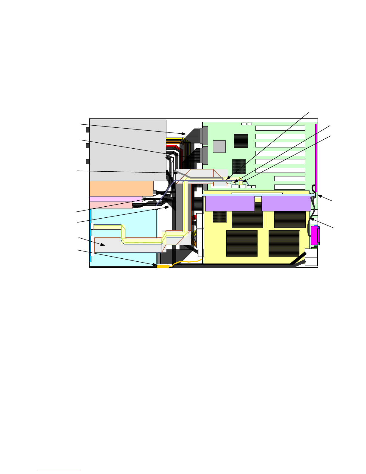
9. Install the air baffle, memory board, and system board access cover.
10. Install the rear access cover, the front access cover, and the bezel.
11. Plug in the AC power cord and turn on power to the server.
Cable connections
1. Basic configuration (the default configuration at system build)
Cable names Part Numbers Qty. Dimensions Descriptions
A U320 SCSI CABLE (104) BB-HDDBA 804-063107-1040 1 1040mm
B BOX-34P CABLE(BEND1) 808-744465-501 1 705mm For signals of Front Panel board
C FDD CABLE(025) 804-062337-525 1 250mm FDD signals
D IDE SIGNAL CABLE(BEND1) 804-062050-501 1 500mm
E HOT-PLUG PCI 28PIN CABLE(0.16) 804-062719-516 1 165mm For signals of HPIB
F FAN SIGNAL CABLE(040) 804-062929-040 1 345mm For signals of FAN BP
G IPMB CABLE(035) 804-062930-035 1 370mm IPMB signals for HDD cage
H ICMB CABLE(035) 804-062931-035 1 355mm ICMB signals
I F/P USB CABLE(160) 804-062932-160 1 595mm USB signals on Front Panel board
J F/P SERIAL CABLE(160) 804-062933-160 1 610mm COM signals on Front Panel board
K OPEN SENSER CABLE(040) 804-062937-040 1 420mm Chassis intrusion
L SCSI 3CONN TERM (160M)(001) 804-062989-001 1 640mm
Figure 46. The cable connection of basic configuration
SCSI(ch.A) on Baseboard – HDD
Cage
Signals for CDROM(master) and
extension devices(slave)
SCSI(ch.B) on Baseboard –
internal peripherals
80
Page 81
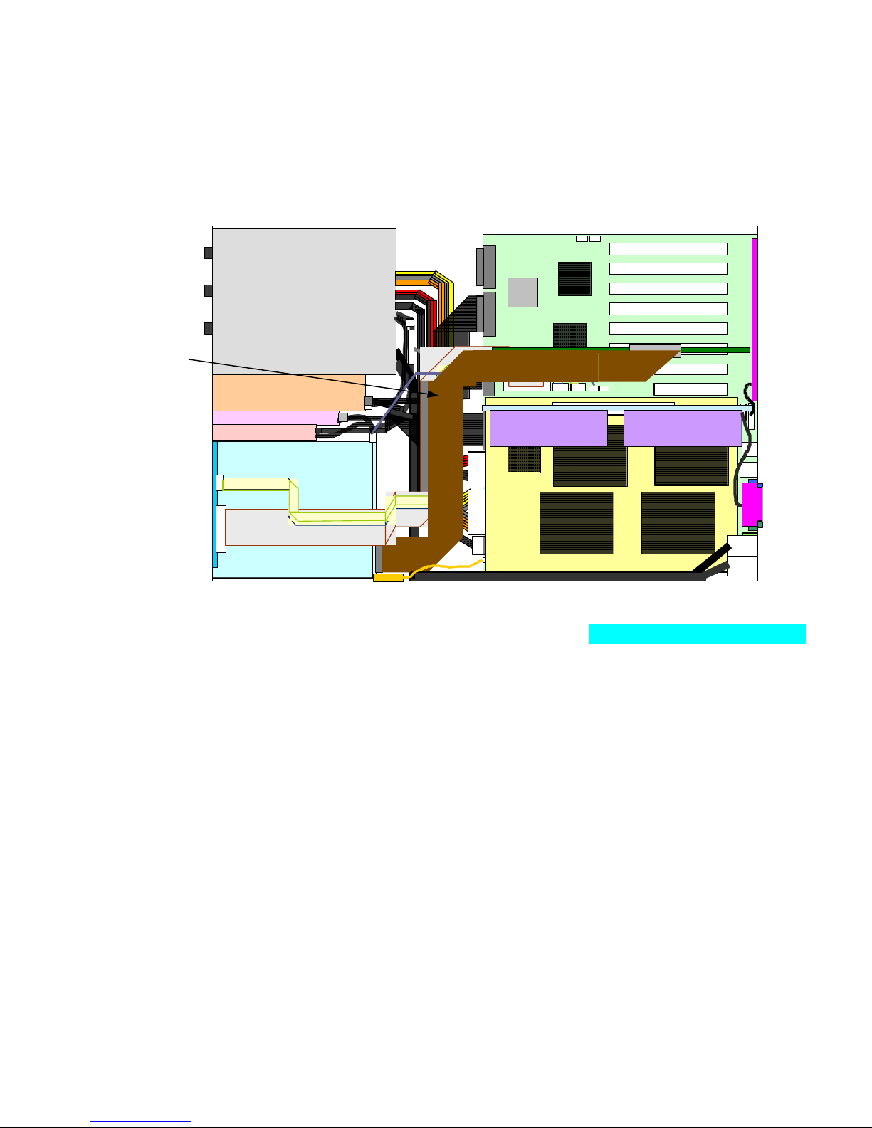
2. Configuration for Disk Array
Reconnect the item A cable which had been connected to “ch.A on Baseboard” at basic
configuration, from “ch.A on Baseboard” to “the connector on DAC card”.
Cable names Part Numbers Qty. Dimensions Descriptions
A U320 SCSI CABLE (104) BB-HDDBA 804-063107-1040 1 1040mm LSI – HDD Cage
B BOX-34P CABLE(BEND1) 808-744465-501 1 705mm For signals of Front Panel board
C FDD CABLE(025) 804-062337-525 1 250mm FDD signals
D IDE SIGNAL CABLE(BEND1) 804-062050-501 1 500mm
E HOT-PLUG PCI 28PIN CABLE(0.16) 804-062719-516 1 165mm For signals of HPIB
F FAN SIGNAL CABLE(040) 804-062929-040 1 345mm For signals of FAN BP
G IPMB CABLE(035) 804-062930-035 1 370mm IPMB signals for HDD cage
H ICMB CABLE(035) 804-062931-035 1 355mm ICMB signals
I F/P USB CABLE(160) 804-062932-160 1 595mm USB signals on Front Panel board
J F/P SERIAL CABLE(160) 804-062933-160 1 610mm COM signals on Front Panel board
K OPEN SENSER CABLE(040) 804-062937-040 1 420mm Chassis intrusion
L SCSI 3CONN TERM (160M)(001) 804-062989-001 1 640mm
Signals for CDROM(master) and
extension devices(slave)
SCSI(ch.B) on Baseboard –
internal peripherals
Figure 47. The cable connection of Disk Array configuration
Installing and Removing Components 81
Page 82

3. In case of providing SCSI (VHDCI) interface onto rear external port
Remove “
basic configuration. Instead by using “
SCSI 3CONN TERM (160M)(001)” which had been connected to ch.B on Baseboard at
0.8MM Pitch EXT. SCSI CABLE (053)” which is attached in
“Accessory kit of system unit”, connect between “ch.B port on Baseboard” and rear external SCSI
(VHDCI) interface port.
Note) In case of this configuration, the removed “SCSI 3CONN TERM (160M)(001)” cable which
had been connected to Internal peripherals needs other SCSI port which is like a optional PCI SCSI
cards.
Cable names Part Numbers Qty. Dimensions Descriptions
A U320 SCSI CABLE (104) BB-HDDBA 804-063107-1040 1 1040mm
B BOX-34P CABLE(BEND1) 808-744465-501 1 705mm For signals of Front Panel board
C FDD CABLE(025) 804-062337-525 1 250mm FDD signals
D IDE SIGNAL CABLE(BEND1) 804-062050-501 1 500mm
E HOT-PLUG PCI 28PIN CABLE(0.16) 804-062719-516 1 165mm For signals of HPIB
F FAN SIGNAL CABLE(040) 804-062929-040 1 345mm For signals of FAN BP
G IPMB CABLE(035) 804-062930-035 1 370mm IPMB signals for HDD cage
H ICMB CABLE(035) 804-062931-035 1 355mm ICMB signals
I F/P USB CABLE(160) 804-062932-160 1 595mm USB signals on Front Panel board
J F/P SERIAL CABLE(160) 804-062933-160 1 610mm COM signals on Front Panel board
K OPEN SENSER CABLE(040) 804-062937-040 1 420mm Chassis intrusion
L
140RC-4 EXT SCSI CBL 804-062722-0531 1 530mm
Figure 48. The cable connection in case of providing rear external VHDCI SCSI port
SCSI(ch.A) on Baseboard – HDD
Cage
Signals for CDROM(master) and
extension devices(slave)
SCSI(ch.B) on Baseboard –
external VHDCI SCSI
82
Page 83

4. In case of providing COM interface onto rear external port
Remove “
basic configuration. Instead by using “
F/P SERIAL CABLE(060)” which had been connected to Serial connector on Baseboard at
RJ45 SERIAL CABLE(035)” which is attached in “Accessory
kit of system unit”, connect between “Serial connector on Baseboard” and rear external COM
interface port.
Cable names Part Numbers Qty. Dimensions Descriptions
A U320 SCSI CABLE (104) BB-HDDBA 804-063107-1040 1 1040mm
B BOX-34P CABLE(BEND1) 808-744465-501 1 705mm For signals of Front Panel board
C FDD CABLE(025) 804-062337-525 1 250mm FDD signals
D IDE SIGNAL CABLE(BEND1) 804-062050-501 1 500mm
E HOT-PLUG PCI 28PIN CABLE(0.16) 804-062719-516 1 165mm For signals of HPIB
F FAN SIGNAL CABLE(040) 804-062929-040 1 345mm For signals of FAN BP
G IPMB CABLE(035) 804-062930-035 1 370mm IPMB signals for HDD cage
H ICMB CABLE(035) 804-062931-035 1 355mm ICMB signals
I F/P USB CABLE(160) 804-062932-160 1 595mm USB signals on Front Panel board
J
RJ45 SERIAL CABLE(135) 804-062988-135 1 350mm
K OPEN SENSER CABLE(040) 804-062937-040 1 420mm Chassis intrusion
L SCSI 3CONN TERM (160M)(001) 804-062989-001 1 640mm
SCSI(ch.A) on Baseboard – HDD
Cage
Signals for CDROM(master) and
extension devices(slave)
“SERIAL” on Baseboard – external
“COM B” port
SCSI(ch.B) on Baseboard –
internal peripherals
Figure 49. The cable connection in case of providing rear external COM port
Installing and Removing Components 83
Page 84

Cable form at maintenance
After Internal maintenance performing, please check and care the following points so that any
internal cables do not have damages by being sandwiched with chassis drives.
At installation of FAN bay、please take care not to bite off
cables.
Figure 50. Caution at Maintenance
84
Page 85

6 Solving Problems
This chapter helps you identify and solve problems that might occur while you are using the system.
Resetting the System
To do this: Press:
Clear system memory, restart POST, and reload the operating system. Reset button
Cold boot reset, which clears system memory, restarts POST, reloads the
operating system, and halts power to all peripherals.
Initial System Startup
Incorrect installation or configuration usually causes problems that occur at initial system startup.
Hardware failure is a less frequent cause. Check the following:
Are all cables correctly connected and secured?
Are the processors fully seated in their sockets on the processor board?
Are all PCI add-in boards fully seated in their slots on the baseboard?
Are all jumper and switch settings on add-in boards and peripheral devices correct? To check
these settings, refer to the manufacturer’s documentation. If applicable, ensure that there are no
conflicts—for example, two add-in boards sharing the same interrupt.
Are all DIMMs installed correctly?
Are all peripheral devices installed correctly?
Are hard disk drives properly formatted or configured?
Are all device drivers properly installed?
Is the operating system properly loaded? Refer to the operating system documentation.
Did you press the system power on/off switch on the front panel to turn the server on (the power-
on light should be lit)?
Are the system power cords properly connected to the system and plugged into a NEMA 6-15R
outlet for 100-120 V∼ or for 200-240 V∼?
Is AC power available at the wall outlet?
Power off/on
If all items are correct and problems persist, contact your service representative or authorized dealer
for assistance.
85
Page 86

Running New Application Software
Problems that occur when you run new application software are usually related to the software.
Faulty equipment is much less likely, especially if other software runs correctly.
Application Software Checklist
Does the system meet the minimum hardware requirements for the software? See the software
documentation.
If you are running the software from a diskette, were the files copied to the diskette correctly?
If you are running the software from a CD-ROM disk, is the disk scratched or dirty?
If you are running the software from a hard drive, is the software correctly installed? Were all
necessary procedures followed and files installed?
Are the correct device drivers installed?
Is the software correctly configured for the system?
Are you using the software correctly?
If problems persist, contact the software vendor’s customer service representative.
After the System Has Been Running Correctly
Problems that occur after the system has been running correctly with no hardware or software
changes often indicate equipment failure. However, recent changes made to the system, such as
hardware or software that has been added or removed, might also be the source of the problems.
Check the following:
If you are running the software from a diskette, try a new copy of the software.
If you are running the software from a CD-ROM disk, try a different disk to see if the problem
occurs on all disks.
If you are running the software from a hard drive, try running it from a diskette. If the software
runs correctly, there might be a problem with the copy on the hard drive. Reinstall the software
on the hard disk, and try running it again. Make sure all necessary files are installed.
If the problems are intermittent, there might be a loose cable, dirt in the keyboard (if keyboard
input is incorrect), a marginal power supply, or other intermittent component failures.
If you suspect that a transient voltage spike, power outage, or brownout might have occurred,
reload the software and try running it again. Symptoms of voltage spikes include a flickering
video display, unexpected system reboots, and the system not responding to user commands.
If all items are correct and problems persist, contact your service representative or authorized dealer
for assistance.
Monitoring POST
When you turn on the system, POST displays messages that provide information about the system.
If a failure occurs, POST emits beep codes that indicate errors in hardware, software, and firmware.
If POST can display a message on the video display, the speaker beeps twice as the message appears.
For a complete list of errors and codes, see page 130.
86
Page 87

Verifying Proper Operation of Key System Lights
As POST determines the system configuration, it tests for the presence of each mass storage device
installed in the system. As POST checks each device, the activity light for that device should turn on
briefly. Check for the following:
Does the diskette drive activity light turn on briefly? If not, see “Diskette Drive Activity Light
Does Not Light” on page 89.
Does the hard disk drive activity light on the control panel turn on briefly? If not, see “Hard
Drive Activity Light Does Not Light” on page 89.
Confirming Loading of an Operating System
Once the system boots up, the operating system prompt appears on the screen. The prompt varies
according to the operating system. If the operating system prompt does not appear, see “Initial
System Startup” on page 85.
Specific Problems and Corrective Actions
This section provides possible solutions for these specific problems:
• Power light does not light
• No beep or incorrect beep pattern
• No characters appear on the screen
• Characters on the screen appear distorted or incorrect
• System cooling fans do not rotate
• Diskette drive activity light does not light
• Hard drive activity light does not light
• CD-ROM drive activity light does not light
• Problems with applications software
• The startup prompt “Press <F2> key if you want to run Setup” does not appear on the screen
• The bootable CD-ROM is not detected
Try the solutions in the order given. If you cannot correct the problem, contact your service
representative or authorized dealer for assistance.
Power Light Does Not Light
Check the following:
Are all the power supplies plugged in? Is the power turned on to the power strip or outlet? Do
you have a blown fuse or breaker?
Is the system functioning normally? If so, the power LED might be defective, the cable from the
front panel to the fan carrier board might be loose, or the cable from the fan carrier board to the
baseboard might be loose.
Are there other problems with the system? If so, check the items listed under “System Cooling
Fans Do Not Rotate Properly” on page 89.
If all items are correct and problems persist, contact your service representative or authorized dealer
for assistance.
Solving Problems 87
Page 88

No Beep Codes
If the system operates normally, but there was no beep, the speaker might be defective. If the
speaker is enabled, but the speaker does not function, contact your service representative or
authorized dealer for assistance.
No Characters Appear on Screen
Check the following:
Is the keyboard working? Check to see that the “Num Lock” light is functioning.
Is the video monitor plugged in and turned on? Many modern video monitors shut down when
inactive and might require a moment to warm up when activated.
Are the brightness and contrast controls on the video monitor properly adjusted?
Are the video monitor switch settings correct?
Is the video monitor signal cable properly installed?
Is the onboard video controller enabled?
If you are using an add-in video controller board, do the following:
1. Verify that the video controller board is fully seated in the PCI add-in board connector (and
verify that the video monitor is plugged in to the active video controller).
2. Reboot the system for changes to take effect.
3. If there are still no characters on the screen after you reboot the system and POST emits a beep
code, write down the beep code you hear. This information is useful for your service
representative.
4. If you do not receive a beep code and characters do not appear:
a. The video display monitor or video controller might have failed. You can verify this by
trying the monitor on another system or trying a different monitor on this system.
b. The system did not find any valid memory installed. Verify that you are using the correct
type of memory for the system and that you have installed it correctly (page 46).
Characters Are Distorted or Incorrect
Check the following:
Are the brightness and contrast controls properly adjusted on the video monitor? See the
manufacturer’s documentation.
Are the video monitor signal and power cables properly installed?
Is the correct monitor/video board installed for your operating system?
If the problem persists, the video monitor might be faulty or it might be the incorrect type. Contact
your service representative or authorized dealer for assistance.
88
Page 89

System Cooling Fans Do Not Rotate Properly
If the system cooling fans are not operating properly, system components could be damaged.
If the system power LED is on, but the fans are not rotating properly, check the following:
Are any of the fan fault indicators lit? Is so, try replacing the corresponding fan module.
Is the cable from the fan carrier board connected to the baseboard?
Are the power supply cables properly connected to the baseboard and the fan carrier board
assembly?
Are there any shorted wires caused by pinched cables or power connector plugs forced into
power connector sockets the wrong way?
If the connections are correct, contact your service representative or authorized dealer for assistance.
Diskette Drive Activity Light Does Not Light
Check the following:
Are the diskette drive power and signal cables properly installed?
Are all relevant switches and jumpers on the diskette drive set correctly?
Is the diskette drive properly configured?
Is the diskette drive activity light always on? If so, the signal cable might be plugged in
incorrectly.
If you are using the onboard diskette controller, use BIOS Setup to make sure that “Onboard Floppy”
is set to “Enabled.” If you are using an add-in diskette controller, make sure that “Onboard Floppy”
is set to “Disabled.”
If the problem persists, there might be a problem with the diskette drive, baseboard, or drive signal
cable. Contact your service representative or authorized dealer for assistance.
Hard Drive Activity Light Does Not Light
If you have installed one or more hard drives in your system, check the following:
Are the power and signal cables to the drive properly installed?
Are all relevant switches and jumpers on the hard drive and adapter board set correctly?
Is the hard drive properly configured?
NOTE
✏
Front panel hard disk LED indicates SCSI devices: The hard drive activity
light on the front panel lights when a SCSI device controlled by the onboard
SCSI host controller is in use. This LED does not display CD-ROM activity.
Solving Problems 89
Page 90

CD-ROM Drive Activity Light Does Not Light
Check the following:
Are the power and signal cables to the CD-ROM drive properly installed?
Are all relevant switches and jumpers on the drive set correctly?
Is the drive properly configured?
Is the onboard IDE controller enabled in the BIOS?
Network Problems
The server hangs when the drivers are loaded.
Change the PCI interrupt settings. Try the “PCI Installation Tips” below.
Diagnostics pass, but the connection fails.
Make sure the network cable is securely attached.
Make sure you specify the correct frame type in your NET.CFG file.
The Link LED does not light.
Make sure you have loaded the network drivers.
Check all cable connections.
Try another port on the hub or switch.
Make sure you have the correct type of cable between the adapter and the hub or switch. Some
hubs and switches require a crossover cable while others require a straight through cable. For
more information on crossover cabling, see your hub or switch documentation.
The Activity LED doesn’t light.
Make sure you’ve loaded the correct network drivers.
The network might be idle. Try accessing a server.
The onboard network interface controller (NIC) stopped working when an add-in adapter was
installed.
Make sure the cable is connected to the port from the onboard NIC.
Make sure your PCI BIOS is current. Try the “PCI Installation Tips” below.
Make sure the other adapter supports shared interrupts. Also, make sure your operating system
supports shared interrupts; OS/2
Try reseating the add-in adapter.
The add-in adapter stopped working without apparent cause.
Try reseating the adapter first; then try a different slot if necessary.
The network driver files might be corrupt or deleted. Delete and then reinstall the drivers.
Run the diagnostics.
†
does not.
90
Page 91

PCI Installation Tips
Check the following:
Some drivers might require interrupts that are not shared with other PCI drivers. For certain
drivers, it might be necessary to alter settings so that interrupts are not shared.
Check PCI interrupt interdependencies among slots and onboard devices.
Problems with Application Software
If you have problems with application software, do the following:
Verify that the software is properly configured for the system. See the software installation and
operation documentation for instructions on setting up and using the software.
Try a different copy of the software to see if the problem is with the copy you are using.
Make sure all cables are installed correctly.
If other software runs correctly on the system, contact your vendor about the failing software.
If the problem persists, contact the software vendor’s customer service representative for assistance.
Bootable CD-ROM Is Not Detected
Check the following:
Is the BIOS set to allow the CD-ROM to be the first bootable device?
Are the jumpers on the CD-ROM drive set correctly?
Are the power and data cables connected properly?
Solving Problems 91
Page 92

Error Messages
If an error occurs in the server, an error message appears on the display unit connected to the server.
Error Messages after Power-on
Powering on the server automatically starts the self-diagnostic program, POST (Power On Self-Test). When the
POST detects any error, it displays an error message and its measure on the display unit.
Follow the table below to troubleshoot such errors. However, even when there is no hardware failure, use of the
keyboard or mouse at the following timing causes the POST to assume a keyboard controller error and stop
processing.
1. Immediately after the server is powered
2. Immediately after the system is rebooted in response to a keyboard instruction (simultaneous key entry of
Ctrl + Alt + Delete)
3. Immediately after the system is rebooted in response to an OS instruction
4. During hardware initialization following restart of the POST
When the POST detects a hardware failure due to the above reason, restart the server once again. If the same error
message reappears, you may assume there is no hardware error. To ensure normal operation of the server, however,
make sure to follow the following restrictions.
5. Do not make any keyboard entry or use the mouse before the memory count appears on the screen
following the server power-on.
6. Do not make any keyboard entry or use the mouse before the start-up message of the SCSI Configuration
Utility appears on the screen following the server reboot.
IMPORTANT: Take a note on the on-screen message before contacting your service
representative. The alarm indication would be a great help for maintenance.
92
Page 93

POST Error Messages
When POST detects an error, it displays an error message on the display unit screen. The following table lists error
messages, descriptions, and actions to take.
IMPORTANT: Take a note on the messages displayed before consulting with your
service representative. Alarm messages are useful information for maintenance.
Error
code
0200 Failure Fixed Disk. Contact your service representative.
0210 Stuck Key. Disconnect the keyboard and connect it again.
0211 Keyboard error.
0212 Keyboard Controller Failed.
0213
0220
0230 System RAM Failed at offset.
0231 Shadow Ram Failed at offset.
0232
0250
0251
0252
0260 System timer error.
0270 Real time clock error.
0271 Check date and time setting.
0280
02B0 Diskette drive A error.
02B1 Diskette drive B error.
02B2 Incorrect Drive A type - run SETUP.
02B3 Incorrect Drive B type - run SETUP.
Error message Recommended Action
isconnect the keyboard and connect it again.
estart the system. If the error cannot be
corrected, contact your service representative.
Keyboard locked - Unlock key
switch.
Monitor type does not match CMOS
- Run SETUP.
Extended RAM Failed at address
line.
System battery is dead - Replace
and run SETUP.
System CMOS checksum bad Default configuration used.
Password checksum bad Passwords cleared.
Previous boot incomplete – Default
configuration used
Release the lock of the key switch. If the error cannot
be corrected in spite of the release of the lock, contact
your service representative.
Start the SETUP. If the error cannot be corrected in
spite of the start of SETUP, contact your service
representative.
Contact your service representative.
Contact your service representative to replace the
battery. (After restarting the computer, start the
SETUP to provide the setting again.)
The default values have just been set. Start the
SETUP to provide the setting again. If the error cannot
be corrected, contact your service representative.
The password has just been cleared. Start the SETUP
to provide the setting again.
Start the SETUP to set the date and time again. If the
same error occurs successively in spite of the
resetting, contact your service representative.
Contact your service representative.
Start the SETUP to set the "Legacy Floppy A" and
"Legacy Floppy B" in the Main menu again. If the
same error occurs successively in spite of the
resetting, contact your service representative.
Start the SETUP to provide the setting again. If the
error cannot be corrected, contact your service
representative.
Solving Problems 93
Page 94

Error
code
02D0 System cache error - Cache disabled.
Error message Recommended Action
The cache cannot be used. Contact your
service representative.
02D1
System Memory exceeds the CPU's caching
Contact your service representative.
limit.
02F5 DMA Test Failed.
02F6 Software NMI Failed.
02F7 Fail-safe Timer NMI Failed.
0500 Expansion ROM not initialized - PCI Slot 01
0501 Expansion ROM not initialized - PCI Slot 02
0502 Expansion ROM not initialized - PCI Slot 03
0503 Expansion ROM not initialized - PCI Slot 04
0504 Expansion ROM not initialized - PCI Slot 05
0505 Expansion ROM not initialized - PCI Slot 06
0506 Expansion ROM not initialized - PCI Slot 07
0507 Expansion ROM not initialized - PCI Slot 08
0611 IDE configuration changed.
0613 COM A configuration changed.
0614 COM A config. error - device disabled.
0615 COM B configuration changed. Contact your service representative.
0616 COM B config. error - device disabled.
0617 Floppy configuration changed.
0618 Floppy config. error - device disabled.
0619 Parallel port configuration changed.
061A Parallel port config. error - device disabled.
0B00 Rebooted during BIOS boot at Post Code.
0B1B PCI System Error on Bus/Device/Function.
0B1C PCI Parity Error on Bus/Device/Function.
0B28
0B29
0B2A
Unsupported Processor detected on
Processor 1.
Unsupported Processor detected on
Processor 2.
Unsupported Processor detected on
Make sure that the server supports the
CPU. If you are not sure, contact your
service representative to request the
maintenance.
Processor 3.
0B2B
Unsupported Processor detected on
Processor 4.
0B30 Fan 1 Alarm occurred.
0B31 Fan 2 Alarm occurred.
0B32 Fan 3 Alarm occurred.
A fan failure or fan clogging may occur.
Contact your service representative to
request the maintenance.
0B33 Fan 4 Alarm occurred.
0B34 Fan 5 Alarm occurred.
0B35 Fan 6 Alarm occurred.
94
Page 95

Error
code
0B50 Processor #1 with error taken off line.
0B51 Processor #2 with error taken offline.
0B52 Processor #3 with error taken offline.
0B53 Processor #4 with error taken offline.
0B5F Forced to use Processor with error
0B60 DIMM group #1 has been disabled
0B61 DIMM group #2 has been disabled
0B62 DIMM group #3 has been disabled
0B70
0B71 System Temperature out of the range.
0B74
0B75 System voltage out of the range.
0B78 The error occurred during fan sensor reading
0B7C
0B7D
0B80 BMC Memory Test Failed.
0B81 BMC Firmware Code Area CRC check failed.
0B82 BMC core hardware failure.
0B83 BMC IBF or OBF check failed.
0B8A BMC SEL area full.
0B8B BMC progress check timeout.
0B8C BMC command access failed.
0B8D Could not redirect the console - BMC Busy 0B8E Could not redirect the console - BMC Error 0B8F
0B90 BMC Platform Information Area corrupted.
0B91 BMC update firmware corrupted.
Error message Recommended Action
The error occurred during temperature sensor
reading.
The error occurred during voltage sensor
reading.
The error occurred during redundant power
module confirmation
The normal operation can't be guaranteed
with use of only one PSU
Could not redirect the console - BMC
Parameter Error -
The CPU is degraded. Contact your service
representative.
Because an error is detected in every CPU,
the system is forcibly started. Contact your
service representative.
Contact your service representative.
Contact your service representative.
A fan failure or fan clogging may occur.
Contact your service representative to
request the maintenance.
Contact your service representative.
Contact you service representative to
replace the power unit.
Contact you service representative to add
an additional power unit or replace the
existing power unit.
Turn off the power once and then on again
to start the server. If the error cannot be
corrected, contact your service
representative.
Solving Problems 95
Page 96

Error
code
0B92
0B93 BMC SDR Repository empty.
0B94 IPMB signal lines do not respond.
0B95 BMC FRU device failure.
0B96 BMC SDR Repository failure.
0B97 BMC SEL device failure.
0B98 BMC RAM test error.
0B99 BMC Fatal hardware error.
0B9A BMC not responding.
0B9B Private I2C bus not responding.
0B9C BMC internal exception.
0B9D BMC A/D timeout error.
0B9E SDR repository corrupt.
0B9F SEL corrupt.
0BB0 SMBIOS - SROM data read error.
0BB1
0BC0
0BC1
0BD0
0BD1 1st SMBus device Error detected.
0BD2 1st SMBus timeout.
0BD3
0BD4 2nd SMBus device Error detected.
0BD5 2nd SMBus timeout.
0BD6
0BD7 3rd SMBus device Error detected.
0BD8 3rd SMBus timeout.
Error message Recommended Action
Internal Use Area of BMC FRU
corrupted.
SMBIOS - SROM data checksum
bad.
POST detected startup failure of 1st
Processor.
POST detected startup failure of
2nd Processor.
1st SMBus address not
acknowledged.
2nd SMBus address not
acknowledged.
3rd SMBus address not
acknowledged.
All the commands and functions other than the FRU
command and the EMP function can be used. This is
not a fatal error. Turn off the power once and then on
again to restart the server. If the error cannot be
corrected, contact your service representative.
Turn off the power once and then on again to restart
the server. If the error cannot be corrected, contact
your service representative.
All the functions other than the function of accessing to
SMC through IPMB can be used. This is not a fatal
error. Turn off the power once and then on again to
restart the server. If the error cannot be corrected,
contact your service representative.
All the commands and functions other than the FRU
command and the EMP function can be used. This is
not a fatal error. Turn off the power once and then on
again to restart the server. If the error cannot be
corrected, contact your service representative.
Turn off the power once and then on again to start the
server. If the error cannot be corrected, contact your
service representative.
Contact your service representative.
Contact your service representative to replace the
CPU.
Contact your service representative to replace the
board specified in the system event log.
96
Page 97

Error
code
Error message Recommended Action
0BD9 4th SMBus address not acknowledged.
0BDA 4th SMBus device Error detected.
0BDB 4th SMBus timeout.
0BDC 5th SMBus address not acknowledged.
0BDD 5th SMBus device Error detected.
0BDE 5th SMBus timeout.
0BE8 IPMB address not acknowledged.
0BE9 IPMB device Error detected.
0BEA IPMB timeout.
8120
Unsupported DIMM detected in DIMM group
#1.
8121
Unsupported DIMM detected in DIMM group
#2.
8122
Unsupported DIMM detected in DIMM group
#3.
8130 Mismatch DIMM detected in DIMM group #1.
8131 Mismatch DIMM detected in DIMM group #2.
8132 Mismatch DIMM detected in DIMM group #3.
8140 DIMM group #1 with error is enabled.
8141 DIMM group #2 with error is enabled.
8142 DIMM group #3 with error is enabled.
8150 NVRAM Cleared By Jumper.
8151 Password Cleared By Jumper.
8160
Mismatch Processor Speed detected on
Processor 1.
8161
Mismatch Processor Speed detected on
Processor 2.
8162
Mismatch Processor Speed detected on
Processor 3.
8163
Mismatch Processor Speed detected on
Processor 4.
8170
Processor 1 not operating at intended
frequency
8171
Processor 2 not operating at intended
frequency
8172
Processor 3 not operating at intended
frequency
8173
Processor 4 not operating at intended
frequency
817F
All processors not operating at intended
frequency
8200 Online Spare Memory was not ready.
Contact your service representative to
replace the board specified in the system
event log.
Contact your service representative.
Contact your service representative to
replace the four DIMMs in the relevant
group.
See the labels put on the DIMMs to make
sure that the DIMMs of the same type are
installed in groups. If DIMMs of different
types are installed in one or more groups,
contact the service representative to replace
DIMMs properly.
Contact your service representative to
replace the four DIMMs in the relevant
group.
Turn off the power. Then recover the
jumper setting to the original setting.
Check the frequency of the CPU. If it is
unknown, contact your service
representative.
DIMM type mismatch is ditected when the
online spare memory feature is enabled.
Contact your service representative.
Solving Problems 97
Page 98

The following figures show the location of specific components referenced in the POST error codes and messages
table listed above.
NOTE: Failed CPU or memory boards can be also identified with the BIOS SETUP
utility.
7. Fans
Fan 5
Fan 4
8. Processors (CPUs)
Processor (CPU) #3
Fan 1
Fan 2
Fan 3
Fan 6
Processor (CPU) #4
Processor (CPU) #2
9. Memory board
The DIMM group consists of four DIMM boards.
DIMM group #3
DIMM group #2
DIMM group #1
Processor (CPU) #1
DIMM group #3
DIMM group #2
DIMM group #1
98
Page 99

Beep Codes
If an error occurs during the POST, the server beeps, indicating the type of error.
Each number indicates the number of short beeps, and a hyphen indicates a pause. For example, the beep interval 1-22-3 indicates 1 beep, pause, 2 beeps, pause, 2 beeps, pause, and 3 beeps notifying that the checksum error occurred on
ROM.
Beep code Description Recommended action
1-2
1-2-2-3 ROM checksum error Replace the baseboard.
1-3-1-1 DRAM refresh test error 1. Check if the DIMM is properly installed.
1-3-1-3 Keyboard controller error 1. Check if the keyboard is properly connected.
1-3-3-1
1-3-4-3 All memory groups error
1-5-1-1 CPU startup error 1. Check if the CPU is properly installed.
1-5-2-1 No CPU error 1. Check if the CPU is properly installed.
1-5-4-4 Power failure
2-2-3-1
Option ROM initialization
error
Video BIOS initialization
error
No memory or capacity
check error
Unexpected interrupt test
error
1. Check if the setting with SETUP is correct.
2. Remove the PCI board and install it again to check
if it operates normally.
3. Replace the PCI board and check if it operates
normally.
4. Replace the baseboard.
1. Check if the connector of the display is properly
connected.
2. Replace the baseboard.
2. Remove the DIMM once, and then re-install it to
check if it operates normally.
3. Ask your service representative to replace the
failed DIMM or baseboard.
2. Replace the baseboard.
1. Check if the DIMM is properly installed.
2. Remove the DIMM once, and then re-install it to
check if it operates normally.
3. Ask your service representative to replace the
failed DIMM or baseboard.
2. Remove the CPU once, and then re-install it to
check if it operates normally.
3. Ask your service representative to replace the
failed CPU or processor board.
2. Remove the CPU once, and then re-install it to
check if it operates normally.
3. Ask your service representative to replace the
failed CPU or processor board.
One of the internal boards has failed. Ask your service
representative to replace the failed board.
Replace the processor or baseboard.
NOTE: Beep code 1-5-4-2 informs you that AC power supply is interrupted due to
power failure or momentary voltage drop and the system is restarted. This is not an error.
Solving Problems 99
Page 100

A Server Description
This chapter provides a general description of the EXPRESS5800/140Rc-4 server.
Feature Summary
Table 8 summarizes the features of the EXPRESS5800/140Rc-4 server platform. Table 2 on
page 17 lists the physical specifications of the server.
Table 8. Feature Summary
Feature Description
Rack mount
design
Configuration
flexibility
Serviceability Front access to hot-swap power supplies and hard disk bays.
Availability Four 64-bit, 100-MHz PCI-X hot plug slots.
Manageability IPMI 1.5 compliant.
Front panel
interface
Compact 4U design (7 inches high and 28 inches deep).
Up to four processors from the Intel® Xeon™ processor family
Eight full length PCI slots (4 PCI-X hot plug, 2 PCI-X non hot plug, 2 PCI non hot
plug).
Two or Three power supplies.
Two Ultra320 SCSI channels.
Up to five 1-inch hot-swap Ultra320 SCSI hard drives.
Slimline 3.5-inch floppy/CD-ROM drive plus one 5.25-inch peripheral bay.
12 GB DDR DRAM memory support.
External I/O and disk expansion.
Built-in 10/100 and Gbit LAN controllers.
Front bezel.
Top access to hot-plug PCI boards and hot-swap fans.
Color coded throughout for serviceable items.
Detailed configuration labels on the system.
Fault indicators and system UID (Unit ID) light.
Up to five 1.0-inch hot-swap Ultra320 disk drives.
Three hot-swap power supply modules in a 2+1 redundant configuration (third module
optional).
Two AC power input cords in a 1+1 redundant configuration.
Six hot-swap system fans in a 5+1 redundant configuration.
WfM 2.0 compliant.
Extensive system sensors and monitoring.
Remote management and diagnostics via Serial or LAN port.
External chassis management via ICMB.
Switches: Power, Reset, NMI, Sleep, Unit ID.
Ports: USB port 3, RJ45 Serial port B.
LEDs: Main power, Standby power, HDD activity, LAN1 activity, LAN2 activity,
General system fault, Unit ID.
100
 Loading...