

Page 1

SRPL8 Server System Product Guide
Order Number: A49445-001
Page 2

Disclaimer
Intel Corporation (Intel) mak es no warranty of any kind with regard t o this material, includi ng, but not limited to, the im pl i ed
warranties of merchantability and fitness for a particular purpose. Int el as sumes no responsibility for any errors t hat may
appear in this document. Intel makes no commitm ent to update nor to keep current the inform ation contained in this
document. No part of this document may be copied or reproduced in any form or by any means without prior wri t ten
consent of Intel.
®
An Intel
product, when used in accordance wi th its associated doc um entation, is "Year 2000 Capable" when, upon
installation, it accurately stores, di splays, processes , provides, and/or receives dat e data from, into, and between the
twentieth and twenty-first centuries, includi ng l eap year calculations, provi ded that all other technology used i n combination
with said product properly exchanges date data with it.
†
Third party brands and names are the property of their respective owners.
Copyright © 2001, Intel Corporation. All rights reserved.
Page 3

Contents
Part I: User’s Guide......................................................................................................... 11
1 Chassis Description
Chassis Feature Summary................................................................................................. 14
Chassis Front Controls and Indicators....................................................................... 15
Chassis Back Controls and Features......................................................................... 17
Peripherals......................................................................................................................... 18
3.5-inch Diskette Drive............................................................................................... 18
3.5-inch Hard Drive Bays........................................................................................... 18
5.25-inch Removable Media Device Bay................................................................... 18
Hot-Swap Power Supplies.................................................................................................. 19
System Cooling.................................................................................................................. 19
2 Boardset Description
Boardset Features .............................................................................................................. 22
Processor Overview................................................................................................... 24
Memory Overview...................................................................................................... 25
DIMM Installation Sequence...................................................................................... 26
Peripherals......................................................................................................................... 27
Super I/O Chip........................................................................................................... 27
Add-In Board Slots............................................................................................................. 27
Video.................................................................................................................................. 27
SCSI Controller .................................................................................................................. 28
IDE Controller..................................................................................................................... 28
Keyboard and Mouse......................................................................................................... 28
Server Management........................................................................................................... 29
Front Panel Controller (FPC)..................................................................................... 30
Hot-swap Controller (HSC)........................................................................................ 30
System Security................................................................................................................. 31
Password Protection.................................................................................................. 31
Secure Boot Mode..................................................................................................... 31
Boot Sequence Control.............................................................................................. 31
Boot Without Keyboard .............................................................................................. 32
Locked Power and Reset Switches............................................................................ 32
Diskette Write Protect................................................................................................ 32
Video Blanking........................................................................................................... 32
Emergency Management Port (EMP)........................................................................ 32
iii
Page 4

3 Configuration Software and Utilities
Hot Keys............................................................................................................................. 34
Power-on Self Test (POST)................................................................................................ 34
Using BIOS Setup.............................................................................................................. 35
Record Your Setup Settings...................................................................................... 35
If You Cannot Access Setup...................................................................................... 35
Starting Setup............................................................................................................ 36
Setup Menus ............................................................................................................. 36
Main Menu................................................................................................................. 38
Advanced Menu......................................................................................................... 41
Security Menu............................................................................................................ 45
Server Menu.............................................................................................................. 46
Boot Menu................................................................................................................. 49
Exit Menu................................................................................................................... 50
Using the System Setup Utility (SSU)................................................................................. 51
When to Run the SSU ............................................................................................... 51
What You Need to Do................................................................................................ 52
Running the SSU....................................................................................................... 52
Customizing the SSU................................................................................................. 55
Launching a Task ...................................................................................................... 56
Resource Configuration Add-In (RCA) Window ......................................................... 56
Multiboot Options Add-In........................................................................................... 57
Security Add-In.......................................................................................................... 57
System Event Log (SEL) Viewer Add-In.................................................................... 58
Sensor Data Record (SDR) Manager Add-In............................................................. 60
Field Replaceable Unit (FRU) Manager Add-In.......................................................... 61
Exiting the SSU.......................................................................................................... 63
Direct Platform Control (DPC) Console.............................................................................. 63
How the DPC Console Works.................................................................................... 63
DPC Console Requirements...................................................................................... 65
Setting Up the Server for the EMP............................................................................. 66
Main DPC Console Window....................................................................................... 67
Server Control Operations......................................................................................... 68
Phonebook ................................................................................................................ 71
Management Plug-Ins................................................................................................ 72
FRU and SDR Load Utility.................................................................................................. 72
When to Run the FRUSDR Load Utility...................................................................... 73
What You Need to Do................................................................................................ 73
How You Use the FRUSDR Load Utility..................................................................... 73
Cleaning Up and Exiting ............................................................................................ 76
Upgrading BIOS................................................................................................................. 77
Preparing for the Upgrade......................................................................................... 77
Upgrading BIOS......................................................................................................... 78
Recovering BIOS....................................................................................................... 79
Changing BIOS Language......................................................................................... 79
Using the Firmware Update Utility...................................................................................... 80
Running the Firmware Update Utility .........................................................................80
iv Contents
Page 5

Installing Video Drivers....................................................................................................... 80
Using the QLogic SCSI Utility............................................................................................. 80
Running the SCSI Utility ............................................................................................ 80
4 Hot-Swapping Fans, SCSI Hard Drives, and Power Supplies
Tools and Supplies Needed................................................................................................ 81
Equipment Log ..........................................................................................................81
Hot-Swapping Fans ............................................................................................................ 82
Hot-Swapping a SCSI Hard Drive....................................................................................... 84
Hot-Swapping Bays................................................................................................... 84
SCSI SCA Hard Disk Drives...................................................................................... 84
Hot-Swapping Power Supplies........................................................................................... 88
Hot-Swapping a Power Supply .................................................................................. 88
Part II: Service Technician’s Guide ........................................................................... 91
5 Working Inside the System
Tools and Supplies Needed................................................................................................ 93
Safety: Before You Remove Server Covers ...................................................................... 93
Warnings and Cautions...................................................................................................... 94
Removing and Installing the Front Bezels .......................................................................... 95
Removing and Installing Server Covers.............................................................................. 96
Removing the PCI Bus Hot-Plug Cover..................................................................... 97
Installing the PCI Bus Hot-Plug Cover....................................................................... 97
Removing the Top Cover........................................................................................... 98
Installing the Top Cover............................................................................................. 99
Removing the Memory Module Cover...................................................................... 100
Installing the Memory Module Cover........................................................................ 100
Fan Array Housing ........................................................................................................... 101
Removing the Fan Array Housing............................................................................ 101
Installing the Fan Array Housing.............................................................................. 101
LCD Module..................................................................................................................... 102
Removing the LCD Module...................................................................................... 102
Installing the LCD Module........................................................................................ 103
Profusion Carrier Tray...................................................................................................... 104
Removing the Profusion Carrier Tray....................................................................... 104
Installing the Profusion Carrier Tray......................................................................... 104
Front Panel Controller Board............................................................................................ 106
Removing the Front Panel Controller Board ............................................................ 106
Installing the Front Panel Controller Board .............................................................. 106
Add-In Boards .................................................................................................................. 108
Installing/Replacing an Add-In Board....................................................................... 108
Removing an Add-In Board...................................................................................... 111
I/O Riser Board................................................................................................................ 111
Removing the I/O Riser Board................................................................................. 111
Installing the I/O Riser Board................................................................................... 112
SRPL8 Server System Product Guide v
Page 6

PHP LED Board ............................................................................................................... 113
Removing a PHP LED Board................................................................................... 113
Installing a PHP LED Board..................................................................................... 114
I/O Tray............................................................................................................................ 114
Removing the I/O Tray............................................................................................. 114
Installing the I/O Tray............................................................................................... 115
Interchassis Management Bus (ICMB) Board................................................................... 116
Removing the ICMB Board...................................................................................... 116
Installing the ICMB Board........................................................................................ 116
AC Filter and Cable.......................................................................................................... 117
Removing the AC Filter and Cable........................................................................... 117
Installing the AC Filter and Cable............................................................................. 117
Peripheral Bay.................................................................................................................. 117
Removing the Peripheral Bay.................................................................................. 117
Installing the Peripheral Bay.................................................................................... 118
Peripheral Bay Backplane................................................................................................ 119
Removing the Peripheral Bay Backplane................................................................. 119
Installing the Peripheral Bay Backplane................................................................... 120
Peripheral Bay Blind Mate Board...................................................................................... 121
Removing the Peripheral Bay Blind Mate Board...................................................... 121
Installing the Peripheral Bay Blind Mate Board........................................................ 123
Diskette Drive................................................................................................................... 124
Removing the Diskette Drive................................................................................... 124
Installing the Diskette Drive ..................................................................................... 125
Peripheral Drives.............................................................................................................. 126
Installing a 5.25-inch Peripheral in the Front Bay..................................................... 126
Removing a 5.25-inch Peripheral from the Front Bay .............................................. 128
6 Upgrading Boardset Components
Tools and Supplies Needed.............................................................................................. 129
Warnings and Cautions.................................................................................................... 130
Cache Coherency Filters: Removing and Installing ......................................................... 132
Removing the Cache Coherency Filters................................................................... 132
Installing the Cache Coherency Filters..................................................................... 133
Processor Retention Bracket: Removing and Installing................................................... 134
Removing the Processor Retention Bracket ............................................................ 134
Installing the Processor Retention Bracket.............................................................. 135
Mezzanine Board(s): Removing and Installing.................................................................. 135
Removing the Mezzanine Board(s).......................................................................... 135
Installing the Mezzanine Board(s)............................................................................ 135
Profusion Carrier: Removing and Installing ..................................................................... 136
Removing the Profusion Carrier............................................................................... 136
Installing the Profusion Carrier................................................................................. 136
PHP I/O Carrier: Removing and Installing ....................................................................... 137
Removing the PHP I/O Carrier................................................................................. 138
Installing the PHP I/O Carrier................................................................................... 138
vi Contents
Page 7

Midplane: Removing and Installing.................................................................................. 140
Removing the Midplane........................................................................................... 140
Installing the Midplane............................................................................................. 140
Memory Modules and DIMMs: Removing and Installing.................................................. 142
Removing a Memory Module................................................................................... 142
Installing a Memory Module..................................................................................... 142
Removing DIMMs.................................................................................................... 144
Installing DIMMs...................................................................................................... 145
Processors: Removing and Installing............................................................................... 147
Removing a Processor ............................................................................................ 148
Installing a Processor .............................................................................................. 149
Front Side Bus (FSB) Termination Board Assembly......................................................... 150
Removing a Termination Board ............................................................................... 150
Installing a Termination Board................................................................................. 151
Replacing the Backup Battery .......................................................................................... 152
7 Solving Problems
Resetting the System....................................................................................................... 155
Initial System Startup ....................................................................................................... 155
Checklist.................................................................................................................. 155
Running New Application Software................................................................................... 156
Checklist.................................................................................................................. 156
After the System Has Been Running Correctly................................................................. 156
Checklist.................................................................................................................. 156
More Problem-Solving Procedures................................................................................... 157
Preparing the System for Diagnostic Testing........................................................... 157
Using PCDiagnostics............................................................................................... 157
Monitoring POST..................................................................................................... 158
Verifying Proper Operation of Key System Lights.................................................... 158
Confirming Loading of the Operating System.......................................................... 158
Specific Problems and Corrective Actions........................................................................ 158
Power Light Does Not Light..................................................................................... 159
No Beep Codes....................................................................................................... 159
No Characters Appear on Screen............................................................................ 159
Characters Are Distorted or Incorrect ...................................................................... 160
System Cooling Fans Do Not Rotate Properly......................................................... 160
Diskette Drive Activity Light Does Not Light............................................................. 160
Hard Disk Drive Activity Light Does Not Light.......................................................... 161
CD-ROM Drive Activity Light Does Not Light........................................................... 161
Network Problems ................................................................................................... 161
PCI Installation Tips................................................................................................. 161
Problems with Application Software.................................................................................. 162
Bootable CD-ROM Is Not Detected.................................................................................. 162
Error and Informational Messages.................................................................................... 162
POST Codes and Countdown Codes....................................................................... 163
POST Error Codes and Messages................................................................................... 167
SRPL8 Server System Product Guide vii
Page 8

8 Technical Reference
Connectors....................................................................................................................... 172
Diskette Drive.......................................................................................................... 174
IRMC Connector...................................................................................................... 175
VGA Video Port....................................................................................................... 176
Keyboard and Mouse............................................................................................... 176
Parallel Port............................................................................................................. 177
Serial Ports A and B................................................................................................ 177
Universal Serial Bus (USB)...................................................................................... 178
SCSI........................................................................................................................ 178
IDE .......................................................................................................................... 179
PCI .......................................................................................................................... 180
Configuration Switches..................................................................................................... 182
General Procedure to Change Switch Settings........................................................ 183
CMOS Clear Switch ................................................................................................. 183
Password Clear Switch............................................................................................ 184
Recovery Boot Switch.............................................................................................. 184
System I/O Addresses...................................................................................................... 185
Memory Map.................................................................................................................... 186
PCI Configuration and Device Map .................................................................................. 187
Interrupts.......................................................................................................................... 187
Video Modes.................................................................................................................... 189
A Power System: Description/Calculating Power Usage
Power System.................................................................................................................. 191
Power Supply Input Voltages................................................................................... 192
Power Supply Output Voltages................................................................................ 192
Server Current Usage ...................................................................................................... 193
Calculating Power Usage................................................................................................. 194
B Equipment Log and Configuration Worksheets
Equipment Log................................................................................................................. 197
Configuration Worksheets........................................................................................ 199
SSU Worksheets..................................................................................................... 199
C Regulatory Specifications
Regulatory and Environmental Specifications................................................................... 207
Environmental Specifications................................................................................... 207
Declaration of the Manufacturer or Importer............................................................ 207
Safety Compliance................................................................................................... 207
Electromagnetic Compatibility (EMC) ...................................................................... 208
viii Contents
Page 9

D Warnings
WARNING: English (US)................................................................................................. 210
AVERTISSEMENT: Français........................................................................................... 212
WARNUNG: Deutsch ...................................................................................................... 214
AVVERTENZA: Italiano................................................................................................... 216
ADVERTENCIAS: Español.............................................................................................. 218
Index.................................................................................................................................... 221
SRPL8 Server System Product Guide ix
Page 10

x Contents
Page 11

Part I: User’s Guide
1 Chassis Description
2 Boardset Description
3 Configuration Software and Utilities
4 Hot-Swapping Fans, SCSI Hard Drives, and Power Supplies
WARNING
Only a QUALIFIED SERVICE TECHNICIAN is authorized to remove
the server covers and to access any of the components inside the server.
Before removing the covers, see “Safety: Before You Remove Server
Covers” on page 93 and “ Warnings and Cautions” on page 94.
This manual is divided into two parts:
• User’s Guide, beginning on page 11—describes procedures that DO NOT REQUIRE internal
server access. You do not need to be a qualified service technician to perform procedures
listed in the User’s Guide.
• Service Technician’s Guide, beginning on page 91—describes procedures that REQUIRE
internal server access. You must be a qualified service technician to perform procedures listed
in the Service Technician’s Guide.
✏
NOTE
The SRPL8 server system is an upgrade to the SRPM8 server system with
PCI-X features added. The SRPL8 server system implements
PCI 2.1-compliant buses with four PCI-X-enabled slots. In this document,
the term “PCI” is loosely used to refer to PCI and PCI-X features. The term
“PCI-X” is limited to references to PCI-X only.
11
Page 12

12 Part 1: User’s Guide
Page 13
1 Chassis Description
The SRPL8 rack server is easy to integrate and can easily accommodate the needs of a variety of
high-performance applications—for example, network servers, multiuser systems, and large
database operations. As your application requirements increase, you can upgrade your server with:
• More powerful and/or additional processors
• An additional processor mezzanine carrier with cache coherency filters
• An additional memory module and additional memory
• Other peripheral devices
• Add-in I/O boards
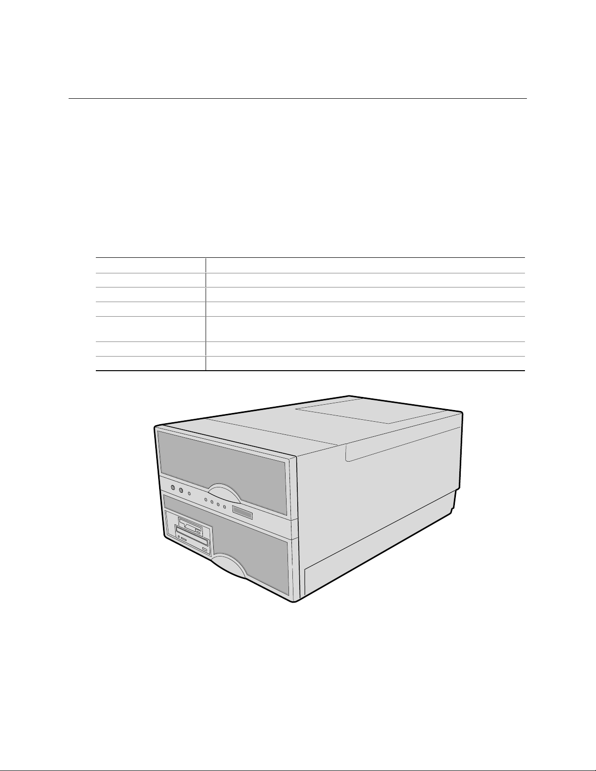
Table 1. Server Physical Specifications
Specification Value
Height 31.12 cm (12.25 inches, 7u)
Width 44.45 cm (17.5 inches)
Depth 71.12 cm (28.0 inches)
Weight 51.4 kg (113 lbs) minimum configuration
60 kg (132 lbs) maximum configuration
Required front clearance 10 inches (inlet airflow <35 °C / 95 °F)
Required rear clearance 8 inches (no airflow restriction)
Figure 1. SRPL8 MP Server
OM08751
13
Page 14

Chassis Feature Summary
Table 2. Chassis Feature Summary
Feature Comment
Power system with r edundancy The 750 watt, 220 VAC autoranging power supplies include integrated
fans for cooling. When the server is configured with three supplies
(2 + 1), the third provides redundancy. The supplies can be replaced—
hot-swapped—without turning off server power. The server requires a
minimum of two power supplies. LEDs on the back of the power supply
indicate power on, failure, and predictive failure.
Server chassis The electrogalvanized metal used in manufacturing the server chassis
minimizes electromagnetic interference (EMI) and radio frequency
interference (RFI).
The peripheral bay provides the interface for 3.5- and 5.25-inch media.
It can support:
• One 5.25-inch IDE CD-ROM drive in the 5.25-inch half-height bay.
(Optional: any IDE or single-ended SCSI device, like a tape drive.)
• Two 3.5-inch wide by 1.0- or 1.6-inch hot-swappable low-voltage
differential SCSI (LVDS) hard disk drives mounted side-by-side in
the 3.5-inch hot-swapping bays. These bays allow hot-swapping of
hard disk drives without shutting down the server.
Ten hot-plug PCI I/O expansion slots (six 33 MHz PCI, four 100 MHz
PCI-X).
The plastic front bezel provides airflow and easy access to drives in the
hot-swapping bays. The removable top covers provide proper airflow
and easy access to components inside the server. Only technically
qualified personnel should remove the server covers.
Cooling system with redundancy Six fans (5 + 1) cool and circulate air through the server. The sixth fan
is redundant. The fans can be replaced—hot-swapped—without
turning off server power. An LED indicator mounted next to each fan
guarantees positive identification of the failed fan.
Integrated power supply fans—two or three—cool and circulate air
through the power supplies and the bottom of the chassis.
Server management Interintegrated circuit bus (I2C) for diagnostic and intrachassis
communication. Interchassis management bus (ICMB) for interchassis
platform management communications.
Real-time clock/calendar (RTC).
Front panel controls and indicators (LEDs).
Basic Input/Output System (BIOS), Power-on Self Test (POST), and
Setup Utility stored in a flash memory device.
System Setup Utility (SSU).
QLogic† SCSI Utility.
Emergency Management Port (EMP) utility.
Field Replacement Unit (FRU) and Sensor Data Record (SDR) load
utility.
14 Chassis Descript ion
Page 15
Chassis Front Controls and Indicators
Q
P
N M LO
HA B C D E F G
K J I
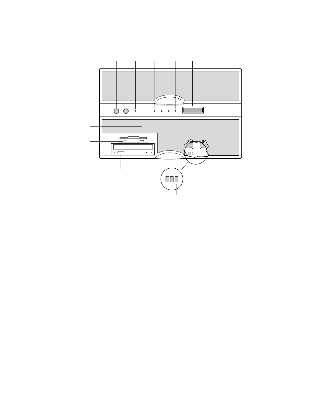
Figure 2. Front Controls and Indicators
OM07301
SRPL8 Server System Product Guide 15
Page 16

Table 3. Front Controls and Indicators
Item Feature Description
Front Panel
A Power switch When pressed, it turns on or off the server. The +5 V standby voltage
is ON whenever the server is plugged in.
B Reset switch When pressed, it resets the server and causes the power-on self test
(POST) to run.
C NMI switch When pressed, it causes a nonmaskable interrupt. This switch is
recessed behind the front panel to prevent inadvertent activation. It
must be pressed with a narrow tool (not supplied).
D Power LED (green) When lit continuously, it indicates the presence of DC power in the
server. When not lit, it indicates power is turned off or power source is
disrupted.
E Power fault LED (yellow) When lit continuously, it indicates presence of DC power.
F Cooling fault LED (yellow) When flashing, it indicates a fan failure.
G Drive fault LED (yellow) When lit continuously, it indicates an asserted fault status on one or
more hard disk drives in the hot-swapping bay. When flashing, it
indicates drive reset in progress.
H Front panel LCD Displays information about processor type and failure codes.
Status LEDs for SCSI Drives in Hot-swapping Bays
I Drive power LED (green) When lit continuously, it indicates the presence of the drive and power
on the drive.
J Drive activity LED (green) Indicates drive activity.
K Drive fault LED (yellow) When lit continuously, it indicates an asserted fault status on one or
more hard disk drives in the hot-swapping bay. When flashing, it
indicates drive reset in progress.
Typical CD-ROM Drive
L Open/close button When pressed, it opens or closes the CD-ROM tray.
M Activity LED When lit, it indicates the drive is in use.
N Volume control It adjusts the volume of headphones or speakers.
O Headphone jack It provides a connection for headphones or speakers.
3.5-inch Diskette (Floppy) Drive
P Activity LED When lit, it indicates the drive is in use.
Q Ejector button When pressed, it ejects the diskette.
16 Chassis Descript ion
Page 17
Chassis Back Controls and Features
A CB
D
E
F
N
G
H
I
M
J
L
K
OM08781
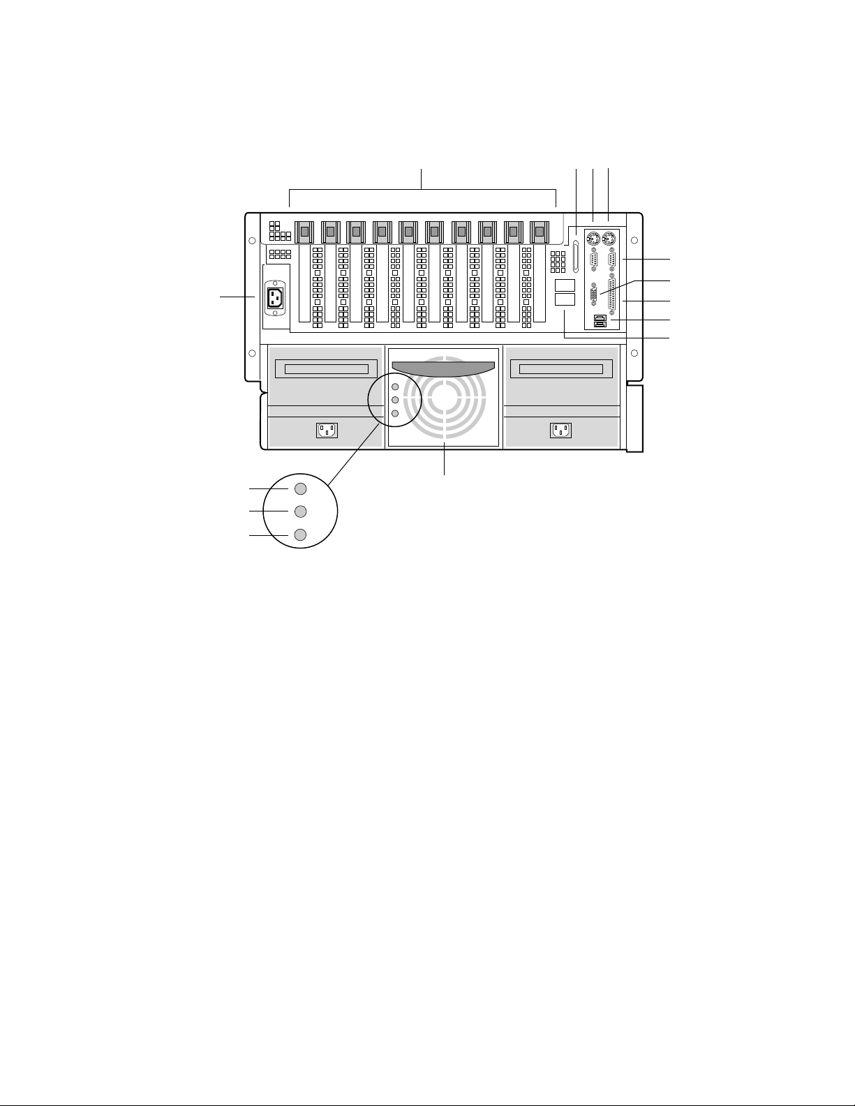
Figure 3. Chassis Back View
A. PCI add-in board expansion slots
B. External LVDS connector
C. PS/2
D. PS/2-compatible keyboard/mouse port, 6-pin
E. PS/2-compatible serial ports A and B, 9-pin RS-232 connector
F. Super VGA compatible, 15-pin video connector
G. PS/2-compatible parallel port (LPT), 25-pin bidirectional subminiature D connector
H. USB ports 0 and 1, 4-pin connector
I. Interchassis Management Bus (ICMB) connectors port 1 and 2
J. Power supplies (in this view, supplies must be populated from left to right; the right
K. Power supply failure LED (yellow)
L. Power supply predictive failure LED (yellow) for power supply fan
M. Power supply power LED (green)
N. AC input power connector
†
-compatible keyboard/mouse port, 6-pin
bay would contain the redundant supply)
SRPL8 Server System Product Guide 17
Page 18

Peripherals
The peripheral bay provides the interface for 3.5-inch and 5.25-inch media.
3.5-inch Diskette Drive
The 3.5-inch diskette drive in the peripheral bay supports 720 KB and 1.44 MB media. The drive
is externally accessible from the front of the system.
3.5-inch Hard Drive Bays
The peripheral bay contains two hot-swapping bays for two 3.5-inch wide (1.0-inch high or
1.6-inch high) wide/fast-20 SCSI III SCA-type hard drives. The hard drives are externally
accessible at the front of the system and connect to a wide LVDS hot-swap SCSI backplane.
As part of the hot-swap implementation, a drive carrier with an integral heatsink is required. The
drives are mounted in the carrier with four fasteners and the carrier snaps into the chassis with a
locking handle. A single metal EMI shield and plastic door cover the drive bays. A hot-swapping
bay is provided for drives that are 3.5 inches wide and 1.0 or 1.6 inches high. Drives can consume
up to 24 watts of power and must be specified to run at a maximum ambient temperature of
40 °C (104 °F).
5.25-inch Removable Media Device Bay
The peripheral bay has one 5.25-inch half-height bay that is accessible from the front of the
system. This bay is intended to provide space for a tape drive for backup or for another removable
device.
We recommend that you do not use this bay for a hard disk drive, because hard disk drives
generate EMI (increasing ESD susceptibility), and because of inadequate cooling.
18 Chassis Descript ion
Page 19

Hot-Swap Power Supplies
The chassis can be configured with two or three 750-watt power supplies in a 2 + 1 redundancy
configuration. If you have three supplies installed, you can hot-swap a failed supply without
affecting system functionality. If you have two supplies installed, they must occupy the left and
center bays (as you face the back of the server—see Figure 3 on page 17). Each supply is designed
to minimize EMI and RFI. This system is designed to operate at 100/200 VAC only.
The DC output voltages of each power supply are:
• +3.3 V at 36.0 A max
• +5 V at 36.0 A max (total combined output of +3.3 V and +5.5 V not to exceed 195 W)
• +12 V at 36.0 A with 42.0 A <10ms peak
• +24 V at 100 mA
• -12 V at 1.0 A
• +5 V standby 1.0 A
Each supply docks to a 36-pin connector on the system midplane.
System Cooling
The server contains two independent cooling subsystems:
• The upper system, cooling the front panel, profusion carrier, and I/O carrier
(5 + 1 redundancy)
• The lower system, cooling the memory modules, peripheral bay, and power supplies
(2 + 1 redundancy)
Both subsystems offer redundant cooling capabilities. As shipped from the factory, the minimum
configuration includes six system fans in the upper subsystem and two power supplies (each has an
integrated fan). You can install one additional power supply.
NOTE
✏
All chassis covers must be on the system for proper cooling.
SRPL8 Server System Product Guide 19
Page 20

20 Chassis Descript ion
Page 21

2 Boardset Description
The modular scaleable architecture of the SRPL8 rack server supports symmetrical
multiprocessing (SMP) and a variety of operating systems. The server comes with Peripheral
Component Interconnect (PCI) and Industry Standard Architecture (ISA) buses. ISA buses are
used internally only. The system has no ISA slots or a way for the user to make use of the ISA
bus. The server boardset consists of a set of printed circuit boards:
• Profusion carrier
Processor mezzanine board(s)
Front side bus (FSB) terminator modules
Cache coherency filters
• PCI hot-plug (PHP) I/O carrier
Low-voltage differential SCSI (LVDS) hot-swap disk backplane
I/O riser board
• Two memory modules
• Front panel controller board
• Midplane
The profusion carrier is mounted horizontally toward the front of the chassis, and the PHP I/O
carrier is mounted horizontally towards the rear of the chassis. The carriers plug into connectors
on the midplane mounted between the two carriers. The midplane interconnects the carriers with
the memory modules and power supplies. The front panel board is mounted in front of the
profusion carrier in the same plane. This board provides the user interface, server management,
cooling system control, and power control.
21
Page 22
D
C
B
A
E
C
F
OM07505
Boardset Features
Table 4. Boardset Features
Feature Description
Profusion carrier The profusion carrier provides the interface for processors (via one or two processor
mezzanine boards), memory modules, and cache coherency filters.
Processor
mezzanine boards
Pentium III Xeon
processor
packaged in an
S.E.C. cartridge
The profusion carrier supports up to two processor mezzanine boards. Each
mezzanine board supports up to four Pentum® III Xeon™ processors.
Installed: Up to eight Pentium III Xeon processors, packaged in single edge contact
(S.E.C.) cartridges and installed in 330-pin Slot 2 processor connectors, operating at
5/12 V. The profusion carrier provides connectors for two processor mezzanine
boards. Each mezzanine board provides four Slot 2 connectors. The carrier's voltage
regulator is automatically programmed by the processor's VID pins to provide the
required voltage.
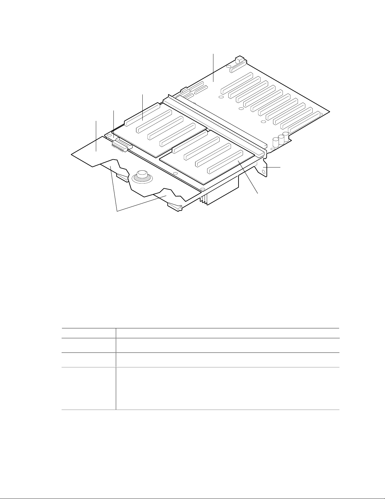
Figure 4. Boardset Overview
A. Front panel board
B. Profusion carrier
C. Processor mezzanine board
D. I/O carrier
E. Midplane
F. Memory modules
continued
22 Boardset Description
Page 23

Table 4. Boardset Features (continued)
Feature Description
Memory modules Two dual plug-in modules containing interleaved pathway to main memory supporting
PC100 registererd SDRAM. Each memory module supports from 128 MB to 16 GB of
error correction code (ECC) memory using sixteen 72-bit dual inline memory modules
(DIMMs). The modules interface to the profusion carrier through the midplane.
FSB terminator
module
Cache coherency
filters
PHP I/O carrier Ten hot-pluggable 64-bit PCI expansion slots (six 33 MHz PCI, four 100 MHz PCI-X).
I/O riser board This board contains all legacy I/O connections; it plugs into an edge connector on the
LVDS hot-swap
disk backplane
Front panel board The front panel board provides the user interface to the server. The board allows
Midplane The midplane:
This module plugs into any unpopulated Slot 2 connector on either processor
mezzanine board. The module terminates the FSB GTL+ signals of the
Slot 2 connector when a processor S.E.C. cartridge is not installed in a connector.
The cache coherency filters contain information on each of the two processor buses,
thus enabling each bus to perform with minimal snoop cycles. The profusion carrier
requires that these filters be populated if the server has two processor mezzanine
boards that are both populated with processors.
Integrated ATI Rage XL graphics (SVGA) controller with 8 MB of video memory.
The QLogic 12160 Ultra 160 LVDS SCSI controller supports two LVDS channels.
One channel is used internally to provide support for the internal SCSI drives
(connected to the LVDS hot-swap disk backplane) and CD-ROM or tape drive. The
second LVDS channel is routed to the rear of the chassis to support external devices.
The diskette controller supports one drive.
The PCI-enhanced Integrated Drive Electronics (IDE) interface supports one IDE bus.
PS/2-compatible keyboard/mouse controller.
Two universal serial bus (USB) ports.
PHP I/O carrier.
PS/2-compatible keyboard and mouse ports (interchangeable).
PS/2-compatible parallel port.
Analog VGA, 15-pin video port.
Two PS/2-compatible, 9-pin serial ports.
This backplane supports hot-swapping of up to two SCA2-type SCSI drives, mounted
in carriers, in and out of the hot-swapping bays.
other servers to communicate with this server, even while power is down, via an
Interchassis Management Bus (ICMB).
Push-button switches control power-up, reset, and nonmaskable interrupt
(NMI) functions.
LEDs indicate power on, power supply failure, hard drive failure, or a fan or other
server cooling failure.
An LCD panel provides information about boot status, available number of
processors, and other server management information.
• Electrically connects the PHP I/O and profusion carriers
• Contains the sockets for the memory modules
• Distributes DC power to the PHP I/O and profusion carrier, disk backplane, cooling
fans, memory boards, and front panel board
• Distributes the power load of the server among two or three 750-watt autoranging
power supplies
SRPL8 Server System Product Guide 23
Page 24

Processor Overview
Each Pentium III Xeon processor is packaged in a single edge contact (S.E.C.) cartridge. The
cartridge includes:
• The processor core with an integrated 32 KB primary (L1) cache
• The secondary (L2) cache
• A thermal plate
• A back cover
Processors used with the SRPL8 server must be:
• 5/12 volts
• 100 MHz FSB
• 1 or 2 MB cache
• Validated by Intel for SRPL8 systems
Each processor implements the MMX™ technology with streaming SMID extensions and
maintains full backward compatibility with the 8086, 80286, Intel386™, Intel486™, Pentium, and
Pentium Pro processors. The processor’s numeric coprocessor significantly increases the speed of
floating-point operations and complies with ANSI/IEEE standard 754-1985.
Each S.E.C. cartridge connects to one of two processor mezzanine boards through a 330-pin
Slot 2 edge connector (SC330.1). The cartridge is secured to the mezzanine carrier by a retention
bracket. Each mezzanine board connects to the profusion carrier. Depending on configuration,
your system has one to eight processors.
The processor external interface is multiprocessor (MP)-ready and operates at 100 MHz. The
processor contains a local APIC unit for interrupt handling in MP and uniprocessor
(UP) environments.
The L2 cache is located on the same die as the processor core and L1 cache. The cache:
• Is offered in 1 MB and 2 MB configurations
• Is ECC protected
• Operates at the full core clock rate
24 Boardset Description
Page 25

Memory Overview
Main memory resides on two add-in boards, called memory modules. Each memory module
contains slots for 16 DIMMs and is attached to the profusion carrier through a 300-pin connector
on the midplane. The memory controller supports PC 100-registered SDRAM DIMMs. Various
DIMM sizes are supported, but each DIMM must be at least 128 MB. Memory amounts from
128 MB to 16 GB per module are supported. The ECC used for the memory module is capable of
correcting single-bit errors (SBEs) and detecting 100% of double-bit errors over one code word.
Nibble error detection is also provided.
You can install:
• From 1 to 32 DIMMs (total number of DIMMs for two memory modules)
• Equal number of DIMMs on each memory module (except when only one DIMM is used)
NOTE
✏
When only a single memory module is installed, DIMM sizes on that
module may vary, but when both memory modules are installed, the DIMM
configuration on the two modules should be identical to support memory
interleaving for performance gains.
Depending on how the memory modules are installed, the memory subsystem can operate in two
different modes: interleaved and single-port.
• Interleaved mode (two memory modules installed): The memory modules share a common
address range. One memory module responds to even-numbered cache lines, while the other
responds to odd-numbered cache lines. This configuration offers the highest performance
because it allows the two modules to be used in a balanced fashion, reducing address conflicts.
To operate in interleaved mode, the DIMMs MUST BE INSTALLED IN PAIRS (ONE ON
EACH MODULE) AND IN THE SAME LOCATIONS ON EACH MODULE.
• Single port mode (one memory module installed): The single memory module responds to all
memory addresses. The DIMMs on this single carrier need not be installed in pairs and can be
installed one DIMM at a time.
SRPL8 Server System Product Guide 25
Page 26

DIMM Installation Sequence
A single carrier will support DIMM population in various configurations (empty sockets included).
However, when fewer than 16 DIMMs are installed on a memory module, the preferred population
order is to start from the lowest J number and populate sequentially to the highest. This
recommendation helps maintain optimal signal integrity and thermal performance.
NOTE
✏
Maximum capacity is limited to 16 GB with one memory module installed.
This increases to 32 GB with two modules.
Some OSs and application programs use base memory while others use both conventional and
extended memory. Examples:
• Base memory: MS-DOS
• Conventional and extended memory: OS/2, Windows NT, and UNIX
MS-DOS does not use extended memory; however, some MS-DOS utility programs like RAM
disks, disk caches, print spoolers, and windowing environments use extended memory for better
performance.
BIOS automatically detects, sizes, and initializes the memory array, depending on the type, size,
and speed of the installed DIMMs, and reports memory size and allocation to the system via
configuration registers.
†
, OS/2, Windows NT†, and UNIX
†
✏
NOTE
DIMM sizes and compatibility: Use DIMMs that have been tested for
compatibility. Contact your sales representative or dealer for a list of
approved DIMMs.
26 Boardset Description
Page 27

Peripherals
Super I/O Chip
The 37C937 Super I/O device supports two serial ports, one parallel port, diskette drive, and
PS/2-compatible keyboard and mouse. The system provides the connector interface for each port.
Serial Ports
Both serial ports are relocatable. By default, port A is physically the left connector (as you look at
the back of the system — see Figure 3 on page 17), port B the right connector. Each serial port
can be set to one of four different COMx ports, and each can be enabled separately. When
enabled, each port can be programmed to generate edge- or level-sensitive interrupts. When
disabled, serial port interrupts are available to add-in boards.
Parallel Port
The 25/15-pin connector stacks the parallel port over the VGA. The 37C937 provides one
IEEE 1284-compatible 25-pin bidirectional EPP (supporting levels 1.7 and 1.9). BIOS
programming of the Super I/O registers enables the parallel port and determines the port address
and interrupt. When disabled, the interrupt is available to add-in boards.
Add-In Board Slots
The I/O carrier has ten 64-bit PCI buses contained in four PCI segments:
• PCI-A provides for PCI slots 1 and 2 (33 MHz), dual-channel LVDS SCSI controller, video,
and PIIX4E.
The PIIX4E controls communications to IDE, onboard ISA, USB, and Super I/O for
handling the keyboard, mouse, diskette drive, parallel port, and serial ports.
• PCI-B provides for PCI slots 3 through 6 (33 MHz).
• PCI-C provides for slots 7 and 8 (two of the 100 MHz PCI-X, 3.3 V slots).
• PCI-D provides for slots 9 and 10 (the two other 100 MHz PCI-X, 3.3 V slots).
Video
The onboard, integrated ATI Rage XL 64-bit VGA chip contains an SVGA controller that is fully
compatible with legacy video standards. The standard system configuration comes with 8 MB of
onboard SDRAM memory. The video controller supports pixel resolutions of up to 1600 x 1200 at
85 Hz and up to 16.7 M colors.
The SVGA controller supports analog VGA monitors (single and multiple frequency, interlaced
and noninterlaced) with a maximum vertical retrace noninterlaced frequency of up to 100 Hz.
You cannot add video memory to this system. Depending on the environment, the controller
displays up to 16.7 M colors in some video resolutions. It also provides hardware-accelerated bit
block transfers (BITBLT) of data.
SRPL8 Server System Product Guide 27
Page 28

SCSI Controller
A QLogic 12160 Ultra 160 SCSI chip provides two 16-bit high-speed SCSI channels. This
high-performance SCSI controller is capable of providing data rates up to 160 MB/sec per channel
in 16-bit operations to ensure maximum data throughput while minimizing PCI bus overhead.
Each channel is capable of operations using either 8- or 16-bit SCSI providing 10 MB/sec
(Fast-10) or 20 MB/sec (Fast-20) throughput, or 20 MB/sec (Ultra), 40 MB/sec (Ultra-wide),
80 MB/sec (40 MHz) (Ultra-2), or 160 MB/sec (40 MHz double clocked) (Ultra 160).
The QLA12160 has its own set of PCI configuration registers and SCSI I/O registers. As a
PCI 2.1 bus master, the controller supports burst data transfers on PCI up to the maximum rate of
132 MB/sec using on-chip buffers.
In the hot-swap SCSI hard drive bay, the system supports up to two 1-inch SCSI hard disk drives.
The 5.25-inch removable media bay supports one SCSI or IDE device (the controller itself
supports more devices, but the 5.25-inch bay can contain a maximum of one device). SCSI
devices do not need to operate at the ultra transfer rate. All drives on the bus must be Ultra 160
(LVD) to run at 160 MB/sec. The 5, 10, and 20 MHz operations can coexist on the bus, and each
device will interact at its appropriate speed.
No logic, termination, or resistor loads are required to connect devices to the SCSI controller other
than termination in the device at the end of the cable. The SCSI bus is terminated on the
I/O carrier with active terminators.
IDE Controller
IDE is a 16-bit interface for intelligent disk drives with AT† disk controller electronics onboard.
The PCI/ISA/IDE Accelerator, called PIIX4E, is a multifunction device on the I/O carrier that acts
as a PCI-based Fast IDE controller. The device controls:
• PIO and IDE DMA/bus master operations
• Mode 4 timings
• Transfer rates up to 22 MB/sec (33 MB/sec using ultra DMA transfers)
• Buffering for PCI/IDE burst transfers
• Master/slave IDE mode
Keyboard and Mouse
The PS/2 compatible keyboard and mouse connectors are mounted in a single-stacked housing
with the mouse connector over the keyboard. External to the system, they appear as two
connectors.
The user can plug in the keyboard and mouse to either connector before powering up the system.
BIOS detects these and configures the keyboard controller accordingly.
The keyboard controller is functionally compatible with the 8042A microcontroller. The system
can be locked automatically if no keyboard or mouse activity occurs for a predefined length of
time, if specified through the SSU (see security options in “Security Add-In” on page 57). Once
the inactivity (lockout) timer has expired, the keyboard and mouse do not respond until the
previously stored password is entered.
28 Boardset Description
Page 29

Server Management
Most of the server management features are implemented using three microcontrollers, the
baseboard management controller (BMC) on the I/O carrier, the front panel controller (FPC) on the
front panel board, and the hot-swap controller (HSC) on the LVDS backplane.
The primary function of the BMC is to autonomously monitor system platform management events
and log their occurrence in the nonvolatile System Event Log (SEL). While monitoring, the BMC
maintains the nonvolatile sensor data record repository (SDRR), from which run-time information
can be retrieved. The BMC provides an ISA host interface to SDRR information, so software
running on the server can poll and retrieve the current status of the platform. A shared register
interface is defined for this purpose.
SEL contents can be retrieved after system failure or during regularly scheduled maintenance. To
retrieve SEL contents, field service personnel use tools such as the SSU SEL Viewer or the
®
Server Control management software.
Intel
The BMC:
• Provides temperature and voltage monitoring
• Monitors processor presence and performs Fault Resilient Booting (FRB) control
• Manages SEL interface
• Manages SDRR interface
• Manages SDR/SEL timestamp clock
• Provides Field Replaceable Unit (FRU) information interface
• Provides system management watchdog timer functions
• Provides pre-timeout (of watchdog timer) SMI capability
• Provides front panel NMI handling
• Provides event receiver functionality
• Manages ISA host and Intelligent Platform Management Bus (IPMB) interface
• Manages secure mode control, front panel lock/unlock initiation, and video blank and diskette
write protect monitoring and control
• Provides sensor event initialization agent
• ACPI Support
SRPL8 Server System Product Guide 29
Page 30

Front Panel Controller (FPC)
The FPC manages:
• Server power control consolidation from several sources
push-button power signal from the front panel connector
real-time clock (RTC)
Intel® remote management card (IRMC), if installed
commands from the Intelligent Platform Management Bus
• Power and reset switch interfaces
• Fault LEDs
• Chassis, midplane and power supplies Field Replacement Unit (FRU) inventory interface
• Server hard reset generation
• Server power fault indication
• Interchassis Management Bus (ICMB) bridge device
• EMP connection
• LCD interface
• Fan predictive failure detection and indicator control
• Power supply predictive failure detection and indicator control
• ACPI Support
• Wake on LAN
†
via Magic Packet† support
Hot-swap Controller (HSC)
The HSC:
• Implements the SAF-TE command set
• Controls the fault lights and drive power-on
• Provides a path for management information via SCSI
• Retrieves drive fault status, backplane temperature, and fan failure information via the IPMB
• Queries the status of the front panel controller for power supply information
• Controls drive power-on and power-down, facilitating hot-swapping
30 Boardset Description
Page 31

System Security
There are several ways to prevent unauthorized entry or use of the server.
Security with BIOS Setup:
• Set server administrative and user passwords.
• Set secure mode to prevent keyboard or mouse input and to prevent use of the front panel
controls.
• For more information, see “Security Menu” on page 45.
Security with the System Setup Utility (SSU):
• Enable the keyboard lockout timer so that the server requires a password to reactivate the
keyboard and mouse after a specified time-out period of 1 to 128 minutes.
• Set an administrative password.
• Set a user password.
• Activate the secure mode hot-key.
• Disable writing to the diskette drive.
• For more information, see “Security Add In” on page 57.
Password Protection
BIOS passwords prevent unauthorized tampering with the server. If you set the user password, but
not the administrative password, BIOS requires you to enter the user password before you can boot
the server or run the SSU. If you set both passwords, entering either password lets you boot the
server or enable the keyboard and mouse. Only the administrative password lets you change the
server configuration with the flash-resident Setup utility.
Secure Boot Mode
Secure boot mode allows the server to boot and run the OS. However, you cannot use the
keyboard or the mouse until you enter the user password.
You can use Setup to put the server in secure boot mode. If BIOS detects a disk in the CD-ROM
drive or a diskette in floppy drive A at boot time, it prompts you for a password. When you enter
the password, the server boots from the disk in the CD-ROM drive or the diskette in drive A.
Entering a password also disables secure mode.
If there is no disk in the CD-ROM drive or diskette in drive A, the server boots from drive C and
automatically goes into secure mode. All enabled secure mode features go into effect at boot time.
If you set a hot-key combination, you can secure the server immediately.
Boot Sequence Contr ol
The BIOS security features determine the boot devices and the boot sequence. They also control
disabling writes to the diskette drive in secure mode. You can use the SSU or Setup to select each
boot device. The default boot sequence is diskette, hard disk, CD-ROM, and network.
SRPL8 Server System Product Guide 31
Page 32

Boot Without Keyboard
The server can boot with or without a keyboard. Before it boots, BIOS displays a message
keyboard detection. During POST, BIOS automatically detects and tests the keyboard if one is
present.
Locked Power and Reset Switches
The power and reset push-button switches on the front panel are locked when the server is in
secure mode. To exit from the secure mode, you must enter your user password.
Diskette Write Protect
If Diskette Write Protect is enabled in Setup, it write-protects the diskette drive only while the
server is in the secure mode. To exit secure mode, enter your user password.
Video Blanking
If Video Blanking is enabled in Setup, the video display will be off when the server is in secure
mode. To exit secure mode, enter your user password.
Emergency Management Port (EMP)
The EMP is a feature of server management. EMP lets the front panel controller (FPC)
communicate with the server via the serial port even if the server power is off. To restrict
EMP access, you can enable an administrator password in Setup. If the administrator enters a new
2
EMP password or clears an old one, BIOS sends the appropriate command via the I
interface to the FPC. To change the password from Setup again, enter the new password twice.
If the administrator sets the Password Clear switch to the Clear position, BIOS clears the
administrator and user passwords (to change switches, see “Configuration Switches” on page 182).
It also attempts to clear the EMP password. If the FPC is not present or is not functioning
properly, BIOS times out and continues.
C bus
32 Boardset Description
Page 33

3 Configuration Software and Utilities
This chapter describes the Power-on Self Test (POST) and system configuration utilities. Table 5
briefly describes the utilities.
Table 5. Configuration Utilities
Utility Description and brief procedure Page
BIOS Setup (“Setup”) You can use Setup to change system configurat ion defaults.
If the system does not have a diskette drive, or the drive is
disabled or misconfigured, use Setup to enable it.
Or, you can move the CMOS switch on the system board from the
default setting (Protect CMOS memory) to the Clear setting; this
will allow most system configurations to boot. For the procedure to
do this, see “CMOS Clear Switch” on page 183. Then run the SSU
to configure the system.
System Setup Utility (SSU) Use for extended system configuration of onboard resources and
add-in boards, viewing the system event log (SEL), setting boot
device pri ority, or setting system security options.
The SSU can be run from either the configuration software
CD-ROM or from a set DOS-bootable diskettes. See the printed
Quick Start Guide
Information entered via the SSU overrides information entered via
Setup.
Direct Platform Control
(DPC) Console
FRUSDR Load Utility Use to update the Field Replacement Unit (FRU), Sensor Data
BIOS Update Utility Use to update BIOS or recover from a corrupted BIOS update. 77
Firmware Update Utility Use to update the BMC flash PROM. 80
QLogic SCSI Utility Use to configure or view the settings of the SCSI host adapters
Use to access and monitor the server remotely. 63
Record (SDR), and Desktop Management Interface (DMI) flash
components.
and onboard SCSI devices in the system.
to make a set of SSU diskettes.
35
51
72
80
33
Page 34

Hot Keys
Use the keyboard’s numeric pad to enter numbers and symbols.
Table 6. Hot Keys
To do this: Press these keys
Clear memory and reload the operating
systemthis is a system reset.
Secure your system immediately. <Ctrl+Alt > + hotkey (Set your hot-key combination with the SSU
Enter BIOS Setup during BIOS POST. F2
Abort memory test during BIOS POST. ESC (Press while BIOS is updating memory size on screen.)
<Ctrl+Alt+Del>
or Setup.)
Power-on Self Test (POST)
Each time you turn on the system, POST starts running. POST checks the carriers, processors,
memory, keyboard, and most installed peripheral devices. During the memory test, POST displays
the amount of memory it is able to access and test. The length of time needed to test memory
depends on the amount of memory installed. POST is stored in flash memory.
1. Turn on your video monitor and system. After a few seconds, POST begins to run.
2. After the memory test, these screen prompts and messages appear:
Keyboard Detected
Mouse Initialized
Press <F2> to enter Setup
3. If you do not press <F2> and do NOT have a device with an OS loaded, the above message
remains for a few seconds while the boot process continues, and the system beeps once. Then
this message appears:
Operating System not found
(To create software installation diskettes, see the printed Quick Start Guide.)
If you do not press <F2>, the boot process continues and this message appears:
Press <Ctrl> <C> to enter SCSI Utility
4. Press <Ctrl+C> if SCSI devices are installed. When the utility opens, follow the displayed
instructions to configure the onboard SCSI host adapter settings and to run the SCSI utilities.
Also see “Using the QLogic SCSI Utility” on page 80. If you do not enter the SCSI utility, the
boot process continues.
5. Press <Esc> during POST to access a boot menu when POST finishes. From this menu, you
can choose the boot device or enter BIOS Setup.
After POST completes, the system beeps once.
What appears next on the screen depends on if you have an OS loaded on the server (or which OS).
If the system halts before POST completes running, it emits a beep code indicating a critical
system error that requires immediate attention. If POST can display a message on the video
display screen, the speaker beeps twice as the message appears.
34 Configuration Software and Utilities
Page 35

Note the screen display and write down the beep code you hear; this information is useful for your
service representative. For a listing of beep codes and error messages that POST can generate, see
Chapter 7, “Solving Problems,” beginning on page 155.
Using BIOS Setup
This section describes BIOS Setup options. Use Setup to change the system configuration
defaults. You can run Setup with or without an OS being present. Setup stores most of the
configuration values in battery-backed CMOS; the rest of the values are stored in flash memory.
The values take effect when you boot the system. POST uses these values to configure the
hardware; if the values and the actual hardware do not agree, POST generates an error message.
You must then run Setup to specify the correct configuration.
†
Run Setup: you can run Setup to modify any standard PC AT
• Select diskette drive
• Select parallel port
• Select serial port
• Set time/date (to be stored in RTC)
• Configure IDE hard drive
• Specify boot device sequence
• Enable SCSI BIOS
feature such as:
Run SSU, not Setup: You must run the SSU instead of Setup to do the following:
• Enter or change information about a board
• Alter system resources (e.g., interrupts, memory addresses, I/O assignments) to user-selected
choices instead of choices selected by the BIOS resource manager
Record Your Setup Settings
Worksheets for recording your settings are in Appendix B, “Equipment Log and Configuration
Worksheets”, starting on page 197. If the default values ever need to be restored (after a CMOS
clear, for example), you must run Setup again. Referring to the worksheets could make your task
easier.
If You Cannot Access Setup
If the diskette drive is misconfigured so that you cannot access it to run a utility from a diskette,
you might need to clear CMOS memory. You must open the system, change a jumper setting, use
Setup to check and set diskette drive options, and change the jumper back. For a step-by-step
procedure, see "CMOS Clear Switch" on page 183.
SRPL8 Server System Product Guide 35
Page 36

Starting Setup
You can enter and start Setup under several conditions:
• When you turn on the system, after POST completes the memory test.
• When you reboot the system by pressing <Ctrl+Alt+Del> while at the DOS operating system
prompt.
• When you have moved the CMOS switch to the “Clear CMOS” position (enabled); for a
step-by-step procedure, see “CMOS Clear Switch” on page 183.
In the three conditions listed above, after rebooting, you will see this prompt:
Press <F2> to enter SETUP
In a fourth condition, when CMOS/NVRAM has been corrupted, you will see other prompts but
not the <F2> prompt:
Warning: cmos checksum invalid
Warning: cmos time and date not set
In this condition, BIOS will load default values for CMOS and attempt to boot.
Setup Menus
Setup has six major menus and several submenus:
1. Main Menu
• IDE submenu
• Keyboard Features submenu
2. Advanced Menu
• PCI Configuration submenu
PCI Mode submenu
• I/O Device Configuration submenu
• Advanced Chipset Control submenu
3. Security Menu
4. Server Menu
• System Management submenu
• Console Redirection submenu
5. Boot Menu
• Boot Device Priority submenu
• Hard Drive submenu
6. Exit Menu
When you see this: What it means:
On screen, an option is shown but you
cannot select it or move to that field.
On screen, the phrase Press Enter
appears next to the option.
36 Configuration Software and Utilities
You cannot change or configure the option in that menu screen.
Either the option is autoconfigured or autodetected, or you must
use a different Setup screen, or you must use the SSU.
Press <Enter> to display a submenu that is either a separate
full-screen menu or a pop-up menu with one or more choices.
Page 37

The rest of this section lists the features that display onscreen after you press <F2> to enter Setup.
Not all of the option choices are described, because (1) a few are not user-selectable but are
displayed for your information, and (2) many of the choices are relatively self-explanatory.
Press To
F1 Get help about an item.
ESC Go back to a previous item.
↑ Select the previous value in a menu option list.
↓ Select the next value in a menu option list.
← → Select a major menu.
- Change the value of the current menu item to the previous value.
+ Change the value of the current menu item to the next value.
Enter Activate submenus, select feature options, and change feature values.
F9 Display the following message:
Setup Confirmation
Load default configuration now?
[Yes] [No]
The [Yes] button will be highlighted. If you press <Enter>, all Setup fields return to their
default values. If you press <ESC> or select No, the server returns to the configuration it
had before you pressed <F9>, without affecting any existing field values.
F10 Display the following message:
Setup Confirmation
Save configuration changes and exit now?
[Yes] [No]
The [Yes] button will be highlighted. If you press <Enter>, all current Setup values are
saved, and the system is reset. If you press <ESC> or select No, the server r eturns to
the configuration it had before you pressed <F10>, without affecting any existing values.
SRPL8 Server System Product Guide 37
Page 38

Main Menu
Default values are in bold typeface.
Feature Option Description
System Time HH:MM:SS Sets the System Time.
System Date MM/DD/YYYY Sets the System Date.
Legacy Diskette A: Disabled
Legacy Diskette B:
Primary Master Selects IDE submenu.
Primary Slave Selects IDE submenu.
Processor Information Selects Processor Information submenu.
Keyboard Features Selects Keyboard Features submenu.
Language
360 KB, 5 ¼”
1.2 MB, 5 ¼”
720 KB, 3 ½”
1.44/1.25 MB, 3 ½”
2.88 MB, 3 ½”
Disabled
360 KB, 5 ¼”
1.2 MB, 5 ¼”
720 KB, 5 ¼”
1.44/1.25 MB, 3 ½”
2.88 MB, 3 ½”
English (US)
French
German
Italian
Spanish
Selects the floppy diskette type for drive A.
Selects the floppy diskette type for drive B.
Selects the language used by BIOS.
38 Configuration Software and Utilities
Page 39

IDE Submenu
Default values are in bold typeface.
Feature Option Description
Type None
Cylinders Displays the number of cylinders.
Heads Displays the number of read/write heads.
Sectors Displays the number of sectors per track.
Maximum Capacity Displays the capacity of the drive.
Multisector Transfers
LBA Mode Control
32-bit I/O
Transfer Mode
Ultra-DMA Mode
CD-ROM
IDE Removable
ATAPI Removable
User
Auto
Disabled
2 sectors
4 sectors
8 sectors
16 sectors
Disabled
Enabled
Disabled
Enabled
Standard
Fast PIO 1
Fast PIO 2
Fast PIO 3
Fast PIO 4
Disabled
Mode 0
Mode 1
Mode 2
If "Auto" is selected, BIOS determines the parameters
during POST.
If "User" is selected, BIOS Setup prompts the user to fill in
the drive parameters. Drive types 1 through 39 are
predetermined drive types.
Displays status of multisector transfers. Autotyped by
BIOS.
Displays status of Logical Block Access. Autotyped by
BIOS.
Enables 32-bit IDE data transfers.
Selects the method for transferring data to/from the drive.
Autotyped by BIOS.
Selects the Ultra-DMA mode used for transferring data
to/from the drive. Autotyped by BIOS.
SRPL8 Server System Product Guide 39
Page 40

Processor Information Submenu
Item Description
Board 1 Processor 1 Stepping ID Displays the processor stepping.
Board 1 Processor 1 L2 Cache Size Displays the L2 cache size.
Board 1 Processor 2 Stepping ID Displays the processor stepping.
Board 1 Processor 2 L2 Cache Size Displays the L2 cache size.
Board 1 Processor 3 Stepping ID Displays the processor stepping.
Board 1 Processor 3 L2 Cache Size Displays the L2 cache size.
Board 1 Processor 4 Stepping ID Displays the processor stepping.
Board 1 Processor 4 L2 Cache Size Displays the L2 cache size.
Board 2 Processor 1 Stepping ID Displays the processor stepping.
Board 2 Processor 1 L2 Cache Size Displays the L2 cache size.
Board 2 Processor 2 Stepping ID Displays the processor stepping.
Board 2 Processor 2 L2 Cache Size Displays the L2 cache size.
Board 2 Processor 3 Stepping ID Displays the processor stepping.
Board 2 Processor 3 L2 Cache Size Displays the L2 cache size.
Board 2 Processor 4 Stepping ID Displays the processor stepping.
Board 2 Processor 4 L2 Cache Size Displays the L2 cache size.
Keyboard Features Submenu
Default values are in bold typeface.
Feature Option Description
Num Lock
Key Click
Keyboard auto-repeat rate
Keyboard auto-repeat delay 1/4 sec
Auto
On
Off
Disabled
Enabled
30/sec
26.7/sec
21.8/sec
18.5/sec
13.3/sec
10/sec
6/sec
2/sec
1/2 sec
3/4 sec
1 sec
Selects power-on state for Num Lock key.
Enables key click.
Selects key repeat rate.
Selects delay before key repeat.
40 Configuration Software and Utilities
Page 41

Advanced Menu
Default values are in bold typeface.
WARNING
Setting items on this menu to incorrect values may cause your system to
malfunction.
Feature Option Description
Processor Serial Number Disabled
Reset Configuration Data
Use Multipro cessor
Specification
Large Disk Access Mode CHS
Pause Before Boot
Hot-plug PCI Master Control
Hot-plug PCI Allocation Level Disabled:
Timeout on POST errors
PCI Configuration Selects PCI Configuration submenu.
I/O Device Configuration Selects I/O Device Configuration submenu.
Advanced Chipset Control Selects Advanced Chipset Control submenu.
Enabled
No
Yes
1.1
1.4
LBA
Disabled
Enabled
Disabled
Enabled
Min.
Max.
Disabled
Enabled
Enables or disables the Processor Serial Number feature
of the Pentium III Xeon processor.
If "Yes" is selected, BIOS clears the System
Configuration Data during the next boot. The field is
automatically reset to "No" in next boot.
Selects the version of the Multiprocessor Specification to
use. Some operating systems require version 1.1 for
compatibility reasons.
Select the drive access method for IDE drives. Most
operating systems use Logical Block Addressing (LBA).
However, some operating systems may use the Cylinder
Head Sector (CHS). See your operating system
documentation for more information.
If enabled, BIOS pauses five-seconds before booting the
operating system.
Set to "Enable" to create the Hot-plug PCI Resource
Table and to reserve resources for each hot-plug PCI
slot.
Set amount of resources to allocate to empty hot-plug
PCI slots.
If enabled, boots operating system after 5 seconds of
displaying POST errors. If disabled, waits for user to
press F1 or F2.
SRPL8 Server System Product Guide 41
Page 42

PCI Configuration Submenu
Default values are in bold typeface.
Feature Option Description
Processor Bus 100 MHz Displays the clock speed of the Processor Bus.
PCI Slots 1-2 PCI 33 Displays the clock speed and setting of PCI Segment A.
PCI Slots 3-6 PCI 33 Displays the clock speed and setting of PCI Segment B.
PCI Slots 7-8 PCI 33
PCI Slots 9-10 PCI 33
PCI Bus Default
PCI Device, Embedded SCSI Selects PCI Mode submenu for the embedded
PCI Slot 1 Selects PCI Mode Submenu for this PCI slot.
PCI Slot 2 Selects PCI Mode Submenu for this PCI slot.
PCI Slot 3 Selects PCI Mode Submenu for this PCI slot.
PCI Slot 4 Selects PCI Mode Submenu for this PCI slot.
PCI Slot 5 Selects PCI Mode Submenu for this PCI slot.
PCI Slot 6 Selects PCI Mode Submenu for this PCI slot.
PCI Slot 7 Selects PCI Mode Submenu for this PCI-X slot.
PCI Slot 8 Selects PCI Mode Submenu for this PCI-X slot.
PCI Slot 9 Selects PCI Mode Submenu for this PCI-X slot.
PCI Slot 10 Selects PCI Mode Submenu for this PCI-X slot.
PCI 66
PCI-X 66
PCI-X 100
PCI 66
PCI-X 66
PCI-X 100
PCI 33
PCI 66
PCI-X 66
PCI-X 100
Displays the clock speed and setting of PCI Segment C.
Displays the clock speed and setting of PCI Segment D.
If no cards are present behind a PCI-X capable bus, this
selects the capabilities of that empty bus. If cards are
present, this option is ignored and the slot speed is
automatically determined.
LVDS controller.
PCI Mode Submenu
Default values are in bold typeface.
Feature Option Description
Option ROM Scan Disabled
Enabled
Enable Master Disabled
Enabled
Latency Timer Default
0020h
0040h
0060h
0080h
00A0h
00C0h
00E0h
42 Configuration Software and Utilities
Enables option ROM scan.
Enables device(s) as a PCI bus master.
Specifies the minimum guaranteed number of PCI bus clocks
that a device can master on a PCI bus during one
transaction.
Page 43

I/O Device Configuration Submenu
Default values are in bold typeface.
Feature Option Description
Serial Port A Disabled
Enabled
Auto
Base I/O Address
Interrupt IRQ3
Serial Port B Disabled
Base I/O Address 3F8h
Interrupt
Parallel Port Disabled
Mode Output only
Base I/O Address
Interrupt IRQ5
DMA channel DMA 1
Floppy disk controller Disabled
3F8h
2F8h
3E8h
2E8h
IRQ4
Enabled
Auto
2F8h
3E8h
2E8h
IRQ3
IRQ4
Enabled
Auto
Bidirectional
EPP
ECP
378h
278h
178h
3BCh
IRQ7
DMA 3
Enabled
Auto
OS Controlled
If set to "Auto", BIOS configures the port.
Selects the base I/O address for COM port A.
Selects the IRQ for COM port A.
If set to "Auto", BIOS configures the port.
Selects the base I/O address for COM port B.
Selects the IRQ for COM port B.
If set to "Auto", BIOS configures the port
Selects the mode of the LPT port.
Selects the base I/O address for LPT port. 178h is only
available when the LPT port is in EPP mode. Otherwise,
3BCh is available.
Selects the IRQ for LPT port.
Selects the DMA channel for LPT port when configured for
ECP mode.
Enables embedded floppy disk controller.
SRPL8 Server System Product Guide 43
Page 44

Advanced Chipset Control Submenu
Default values are in bold typeface.
Feature Option Description
Extended RAM Step
L2 Cache Disabled
Multiboot Support
Override PHP Switches
2 GB Memory Limit
1 MB
1 KB
Every location
Enabled
Disabled
Enabled
Disabled
Enabled
Disabled
Enabled
Selects the thoroughness of the extended memory test. If
“1 MB” is selected, BIOS tests each 1 MB boundary.
If “1KB” is selected, BIOS tests each 1 KB boundary.
If "Every location" is selected, BIOS tests every byte. BIOS
defaults to the fastest test.
Enables the second level cache. The second level cache
should be disabled only for diagnostic purposes.
Enables Boot Device Selection.
If enabled, the individual slot switches cannot power down
the slots. If disabled, the power to each slot can be removed
by the individual slot switches.
If enabled, BIOS limits the top of memory to 2 GB. Additional
memory becomes inaccessible.
44 Configuration Software and Utilities
Page 45

Security Menu
Default values are in bold typeface.
Feature Option Description
User Password Is Set
Administrator Password Is Set
Set User Password Press Enter When the Enter key is pressed, the user is prompted for a
Set Administrator Password Press Enter When the Enter key is pressed, the user is prompted for a
Password on Boot
Secure Mode Timer
Secure Mode Hot Key
(Ctrl+Alt+X)
Secure Mode Boot
Video Blanking
Floppy Write Protect
Front Panel Lockout
Clear
Clear
Disabled
Enabled
Disabled
1 min
2 min
5 min
10 min
20 min
1 hr
2 hr
Disabled
[“X” = A-Z]
Disabled
Enabled
Disabled
Enabled
Disabled
Enabled
Disabled
Enabled
Status only. Administrator password must be enabled
before user password can be enabled. User password is
enabled by entering a user password and disabled by
entering a null user password.
Status only. Enabled by entering an administrator
password and disabled by entering a null administrator
password.
password; press ESC key to abort.
password; press ESC key to abort.
Requires password entry on boot. The system remains in
Secure Mode until password is entered. Password on
Boot takes precedence over Secure Mode Boot.
Sets the period of key/PS2 mouse inactivity specified
before Secure Mode activates. Requires a password for
Secure Mode to function.
Assigns a hot key that invokes Secure Mode.
Enabled system boots in the secure mode. Requires a
password to unlock the syst em.
Blank video when Secure Mode is activated. Requires a
password to unlock the syst em.
When Secure Mode is activated, the floppy drive is writeprotected. Requires a password to re-enable floppy
writes.
When Secure Mode is activated, the Reset and Power
switches are locked. Requires a password is required to
unlock the system.
SRPL8 Server System Product Guide 45
Page 46

Server Menu
Default values are in bold typeface.
Feature Option Description
System Management Selects System Management submenu.
Console Redirection Selects Console Redirection submenu.
Processor Rete st
EMP Password Switch
EMP Password Selects the EMP password.
EMP ESC Sequence Updated from the Front Panel Controller firmware.
EMP Hangup Line String Updated from the Front Panel Controller firmware.
Modem Initialization
String
High Modem Initialization
String
EMP Access Mode Preboot Only
EMP Restricted Mode
Access
EMP Direct
Connect/Modem Mode
No
Yes
Disabled
Enabled
Always Active
Disabled
Disabled
Enabled
Direct Connect
Modem Mode
Select “Yes” to clear historical processor status and retest
all processors on the next boot.
Enables the EMP password.
Updated from the Front Panel Controller firmware.
Updated from the Front Panel Controller firmware.
Selected when the EMP is enabled.
Preboot Only: EMP is enabled during power down or POST
only.
Always Active: EMP is always enabled.
Disabled: EMP is disabled.
Enables Restricted Mode. In Restricted Mode, Power
Down, Front Panel NMI, and Reset Control via EMP are
disabled.
Allows the user to connect to a local machine without using
a modem.
46 Configuration Software and Utilities
Page 47

System Management Submenu
Default values are in bold typeface.
Feature Option Description
Firmware SMIs Disabled
Enabled
System Event Logging Disabled
Enabled
Clear Event Log
Memory Scrubbing
AERR Enable Disabled
Assert NMI on BERR Disabled
Assert NMI on PERR Disabled
Assert NMI on SERR Disabled
Enable Host Bus Error Disabled
FPC Error Check
HSC Error Check
Server Management Information Selects Server Management Information submenu.
Disabled
Enabled
Disabled
Enabled
Enabled
Enabled
Enabled
Enabled
Enabled
Disabled
Enabled
Disabled
Enabled
Enables SMI generation by agents on the Intelligent
Platform Management Bus (IPMB). Because BIOS
requires SMIs for various tasks, setting thi s field to
disabled does not disable all sources of SMIs.
Enabled: logs critical system events.
Clears the System Event Log (SEL). This option is reset
to Disabled on each boot.
Enables memory scrubbing by the Profusion chip set.
Enables AERR to be asserted on the processor host
buses.
Enables BERR to be reported as a critical event via NMI.
Requires SERR to be enabled as well.
Enables PERR to be reported as a critical event via NMI.
Requires SERR to be enabled as well.
Enables SERR to be reported as a critical event via NMI.
Enables ECC checking on the processor buses.
Enables Front Panel Controller (FPC) checking. If
enabled, BIOS verifies that it can communicate with the
FPC.
Enables Hot-swap Controller (HSC) checking. If
enabled, BIOS verifies that it can communicate with the
HSC.
SRPL8 Server System Product Guide 47
Page 48

Server Management Information Submenu
Feature Option Description
Board Part Number Displays Board Part Number.
Board Serial Number Displays Board Serial Number.
System Part Number Displays System Part Number.
System Serial Number Displays System Serial Number.
Chassis Part Number Displays Chassis Part Number.
Chassis Serial Number Displays Chassis Serial Number.
BMC Revision Displays Baseboard Management Controller Revision.
FPC Revision Displays Front Panel Controller Revision.
HSC Revision Displays Hot-swap Controller Revision.
Console Redirection Submenu
Feature Option Description
COM Port Address
IRQ #
COM Port Baud
Rate
Flow Control No Flow Control
Disabled
3F8
2F8
3E8
3
4
9600 K
19.2 K
38.4 K
115.2 K
CTS/RTS
XON/XOFF
CTS/RTS + CD
When enabled, use the I/O port specified.
When enabled, use the IRQ specified.
When enabled, use the baud rate specified. The maximum
baud rate supported by the Emergency Management Port is
19.2K.
When enabled, use the flow control type specified.
48 Configuration Software and Utilities
Page 49

Boot Menu
Boot Menu options allow the user to select the boot device. The following table shows an example
list of devices ordered in priority of the boot invocation. Items can be reprioritized by using the
Up and Down arrow keys to select the device. Once the device is selected, use the + (plus) key to
move the device higher in the boot priority list. Use the – (minus) key to move the device lower in
the boot priority list.
Feature Option Description
Floppy Check
Boot Device Priority Selects the Boot Device Priority submenu.
Hard Drive Selects the Hard Drive submenu.
Removable
Devices
Removable Format Selects the Removable Format submenu.
Maximum Number
0 Drives
of I
2
Message Timeout
Multiplier
Pause During
POST
Disabled
Enabled
1
4
1
2
4
8
10
50
100
1000
Disabled
Enabled
Disabled speeds up the boot process.
Enabled verifies the floppy type on boot.
Selects the Removable Devices submenu.
Selects the maximum number of I20 drives that will be
assigned a DOS drive.
0 message timeout values are multiplied by this
All I
2
number.
Use this to start the IRTOS (I
System) manually. When POST has stopped, it
issues three beeps. Press any key to continue
POST.
0 Real-time Operating
2
SRPL8 Server System Product Guide 49
Page 50

Exit Menu
The following menu options are available on the Server menu. Select an option by using the Up or
Down arrow keys. Then press <Enter> to execute the option, and follow the prompts.
Option Description
Exit Saving Changes Exit Setup and save changes.
Exit Discarding Changes Exit Setup without saving changes.
Load Setup Defaults Load default values for all Setup items.
Load Custom Defaults Load settings from Custom Defaults.
Save Custom Defaults Save changes as Custom Defaults. If CMOS fails, BIOS uses Custom
Defaults if available. If not, it uses the factory defaults.
Discard Changes Load previous values of all Setup items.
Save Changes Save all changes.
50 Configuration Software and Utilities
Page 51

Using the System Setup Utility (SSU)
The SSU is on the configuration software CD-ROM shipped with the server. The SSU provides a
graphical user interface (GUI) over an extensible framework for server configuration. The
SSU framework supports the following functions and capabilities:
• Assigns resources to devices and add-in boards before loading the OS.
• Lets you specify boot device order and system security options.
• Permits viewing and clearing of the system event log (SEL).
• Permits viewing of the system field replaceable units (FRUs) and sensor data records (SDRs).
• Allows troubleshooting of the server when the OS is not operational.
• Provides a system-level view of the server I/O devices.
• Supports saving and restoring system configuration.
When to Run the SSU
The SSU is a DOS-based utility that supports extended system configuration operations for
onboard resources and add-in boards. You can also view the SEL and set system boot and security
options. Use the SSU when you need to:
• Add and remove boards affecting the assignment of resources (ports, memory, IRQs, DMA).
• Modify the server’s boot device order or security settings.
• Change the server configuration settings.
• Save the server configuration.
• View or clear the SEL.
• View FRU information.
• View the SDR table.
The SSU is PCI-aware and works with any compliant configuration (.CFG) files supplied by the
peripheral device manufacturer.
The I/O carrier comes with a .CFG file describing the characteristics of the carrier and the system
resources it requires.
To specify a system configuration, SSU uses the information provided by:
• .CFG files.
• Configuration registers.
• Flash memory.
• The information that you enter.
The SSU then writes the configuration information to flash memory.
The SSU stores configuration values in flash memory. These values take effect when you boot the
server. POST checks the values against the actual hardware configuration; if the values do not
agree, POST generates an error message. You must then run the SSU to specify the correct
configuration before the server boots.
The SSU always includes a checksum with the configuration data so BIOS can detect any potential
data corruption before the actual hardware configuration occurs.
SRPL8 Server System Product Guide 51
Page 52

What You Need to Do
You can run the SSU directly from the configuration software CD-ROM after you have installed a
CD-ROM drive, or from a set of DOS diskettes.
If you choose to run the SSU from DOS diskettes, you must copy the SSU from the CD-ROM to
the diskettes and follow the instructions in the included README.TXT file to prepare the
diskettes.
If your diskette drive is disabled or improperly configured, you must use the flash-resident Setup
utility to enable it so you can use the SSU. If necessary, you can disable the drive after exiting the
SSU. Information entered using the SSU overrides any entered using Setup.
Running the SSU
Running the SSU Locally
Running the ssu.bat file provided on the SSU media starts the SSU. If the server boots directly
from the SSU media, the ssu.bat file runs automatically. If the server boots from different media,
the SSU can be started manually or by another application. When the utility starts in the local
execution mode (the default mode), the SSU accepts input from the keyboard and/or mouse. The
SSU presents a VGA-based GUI on the primary monitor.
The SSU runs from writable, nonwritable, removable, and nonremovable media. If the SSU is run
from nonwritable media, user preference settings (like screen colors) cannot be saved.
The SSU supports the ROM-DOS V6.22 OS. It can run on other ROM-DOS compatible OSs, but
they are not supported. The SSU will not operate from a “DOS window” running under an OS like
†
Windows
.
Running the SSU Remotely
To run the SSU remotely, you must use one of two mechanisms:
• Graphical hardware redirection through the Intel remote management card (IRMC)
• BIOS console redirection
NOTE
✏
The SSU supports a text mode of operation versus the default VGA graphics
mode. Some forms of remote operation require that the SSU be operated in
text mode. In text mode, the SSU screens are constructed using only
character-based graphics and colors. The primary benefit of text mode is the
reduced amount of display information that needs to be communicated to a
remote console. Support for text mode operation also allows the SSU to be
operated remotely via modem using existing technologies, with no
modification to the SSU required.
To start the SSU in text mode, type “AF/t” from the command line in the
SSU subdirectory (the directory containing the af.exe file). Depending on
the mode of execution, this could involve exiting the SSU to reach the
command prompt, then restarting the SSU in text mode.
52 Configuration Software and Utilities
Page 53

Graphical Hardware Redirection through t he Intel Remote Management Card (IRMC)
Using graphical hardware redirection through the IRMC, you can:
• See the SSU console in VGA graphics mode.
• Control the mouse.
• Control the keyboard from a local system connected to a remote server by a network or
modem.
The IRMC provides video memory, keyboard, and mouse redirection support. Video memory and
user input is sent to a remote location through either a modem or Ethernet link and displayed by
the remote control console. This solution requires an IRMC board installed in the remote server
and the remote control software available on the local system. In this model of remote operation,
the SSU executes exclusively on the remote server. Any files required for the SSU to execute must
be on the remote server (on removable or nonremovable media). Downloading the SSU to a
remote server is not explicitly supported by the SSU, but using a third-party software package to
download the required SSU files to the remote server is not prohibited.
BIOS Console Redirection
Using BIOS console redirection, you can:
• See the SSU console.
• Control the keyboard from a local system connected to a remote server by a modem or direct
serial connection.
The local system must run terminal emulator software capable of supporting ANSI terminal
sequences. BIOS console redirection provides text mode video and keyboard redirection support
only. It does not support redirection of the mouse.
Text mode video and user input is sent to a remote location through either a modem or direct serial
link and is displayed by the terminal emulator software on the local system.
In this model of remote operation, the SSU executes in text mode exclusively on the remote server.
Any files required for the SSU to execute must be on the remote server (on removable or
nonremovable media).
Direct Platform Control (DPC) Consol e
Using the DPC console in conjunction with BIOS console redirection, you can:
• See the BIOS Setup Screen (F2)
• Control the keyboard from a local system connected to a remote server by a modem or direct
serial connection
The local system must be running the DPC console software. This method of redirection provides
text mode video and keyboard redirection support only. It does not support redirection of the
mouse.
For specific instructions on implementing the DPC console, see "Direct Platform Control (DPC)
Console" on page 63.
SRPL8 Server System Product Guide 53
Page 54

Starting the SSU
The SSU is a collection of task-oriented modules plugged into a common framework called the
Application Framework (AF). The AF provides a launching point for individual tasks and a
location for setting customization information.
1. Turn on your video monitor and your system.
2. Start the SSU through one of two ways:
• After creating a set of SSU diskettes from the CD-ROM: Insert the first SSU diskette
in drive A. Press the reset button or <Ctrl+Alt+Del> to reboot your server from the
diskette.
• Directly from the Server Configuration Software CD-ROM: Insert the configuration
software CD-ROM into your CD-ROM drive. Press the reset button or <Ctrl-Alt-Del> to
reboot. When prompted to do so, press <F2> to enter BIOS Setup. From the Boot Menu,
select the Boot Device Priority option. Select CD-ROM as your primary boot device.
Save those settings and exit BIOS Setup. The server will boot from the CD-ROM and
display a menu of options. Follow the instructions in the menu to start the SSU.
3. When the SSU title appears on the screen, press <Enter> to continue.
4. The mouse driver loads if it is available; press <Enter> to continue.
This message appears:
Please wait while the Application Framework loads....
When the main window of the SSU appears, you can customize the GUI before continuing.
See “Customizing the SSU” on page 55.
Figure 5. SSU Main Window
54 Configuration Software and Utilities
Page 55

Customizing the SSU
You can customize the GUI according to your preferences. The AF sets these preferences and
saves them in the AF.INI file so that they take effect the next time you start the SSU. Use these six
user-customizable settings:
• BackColor—(default = 3) lets you change the BACKGROUND color associated with
different items on the screen to predefined color combinations. The changes are instantaneous.
• Color—(default = 0) lets you change the WINDOW color preference selection to predefined
color combinations. The changes are instantaneous.
• UserMode—(default = expert) lets you set the desired expertise level.
Novice
Intermediate
Expert
The expertise level determines which tasks are visible in the Available Tasks section and what
actions each task performs. For a new mode setting to take effect, you must exit the SSU and
restart it. In the current implementation, there is no distinction between these three different
modes.
• Language—(default = EN) lets you change the text displayed in the SSU to the appropriate
language. For a new language setting to take effect, you must exit the SSU and restart it. For
a list of Alpha-2 language codes, see the ISO 639:1988 and ISO 3166-1993 specifications.
• Locale—(default = US) lets you change the current locale used in the SSU environment. For a
new locale to take effect, you must exit the SSU and restart it. For a list of Alpha-2 locale
codes, see the ISO 639:1988 and ISO 3166-1993 specifications.
• Other—lets you change other miscellaneous options in the SSU. The changes are immediate.
To change the interface default values:
• Use the mouse to click the proper button in the Preferences section of the SSU Main window.
OR
• Use the tab and arrow keys to highlight the desired button, and press the spacebar or <Enter>.
OR
• Access the menu bar with the mouse or hot keys (Alt + underlined letter).
NOTE
✏
If you run the SSU from nonwritable media (like a CD-ROM), these
preferences will be lost when you exit the SSU.
SRPL8 Server System Product Guide 55
Page 56

Launching a Task
It is possible to have many tasks open at the same time, although some tasks might require
complete control to avoid possible conflicts. A task achieves complete control by commanding the
center of operation until you close the task window.
To launch a task:
• In the SSU Main window, double-click the task name under Available Tasks to display the
main window for that task, OR
• Highlight the task name, and click <OK>, OR
• Use the tab and arrow keys to highlight the desired button, and press the spacebar or <Enter>.
Resource Configura tion Add-In (RCA) Window
The RCA provides three major functions:
• Creates representations of devices that cannot be discovered by the system.
• Modifies the contents of the system by adding and removing devices.
• Modifies the resources used by devices.
1. From the SSU main window, launch the RCA by selecting the “Resources” task under the
RCA heading in the task box.
2. When the RCA window appears, it displays messages similar to the following:
Baseboard: System Board
PCI Card: Bus 00 dev 00 -– Host Processor Bridge
PCI Card: Bus 00 dev 0D –- Multifunction Controller
PCI Card: Bus 00 dev 0F –- Ethernet Controller
PCI Card: Bus 00 dev 12 –- Multifunction Controller
PCI Card: Bus 00 dev 14 –- VGA Controller
3. To configure a device, click it or select its name in the Devices section of the RCA window,
and press the spacebar or <Enter>.
4. You can close the RCA window and return to the AF by clicking on the Close button. Any
changes made will be kept in memory for use by the RCA when it is rerun.
5. Save all changes by clicking <Save>. Saving writes your current configuration to nonvolatile
storage where it will be available to the system after every reboot.
6. To discard all changes, close the window by clicking on the system menu (the dash in the
upper-left corner). Do not do this if you want to save changes (step 5).
Modifying Resources
You might need to modify the resources of a device to accommodate certain OSs, applications, and
drivers. You might also need to modify resources to resolve a conflict.
To modify the resources associated with a device:
1. Highlight the device in the Devices section of the RCA window.
2. Press the spacebar or <Enter>, or double-click the entry.
This displays the functions of the selected device along with possible choices and the resources
associated with those choices.
56 Configuration Software and Utilities
Page 57

To make a modification:
1. Highlight the function in the Configuration window.
2. Press the spacebar or <Enter>, or double-click the entry (this updates the choice and resource
lists).
3. Press the tab key to get to the choice list, and press <Enter>.
4. Use the arrow keys to select a proper choice, and press <Enter> again.
5. If the choice allows multiple possible values for a particular resource, use the hot key to select
a resource and press the spacebar or double-click the resource.
6. Select the desired resource, and click <OK>.
System Resource Usage
Click <Resource Use> in the Configuration window to display the System Resource Usage
window, which shows the resources each device consumes. This information is useful if a conflict
occurs. Devices can be organized according to the resources you want to examine using the
options in the Resource section of the screen. The resource information can also be written to a
plain text file through this window.
Multiboot Options Add-In
In this window, you can change the boot priority of a device.
1. Select a device.
2. Press <+> to move the device up in the list (higher priority). Press <-> to move it down.
Security Add-In
In this window, you can set the user and administrator passwords and security options.
To Set the User Password
1. Click <User Password>.
2. Enter the password in the first field.
3. Confirm the password by entering it again in the second field.
To Change or Clear the User Password
1. Click <User Password>.
2. Enter the old password in the first field.
3. Enter the new password in the second field (or leave blank to clear).
4. Confirm the password by entering it again in the second field (or leave blank to clear).
To Set the Administrator Password
1. Click <Administrator Password>.
2. Enter the password in the first field.
3. Confirm the password by entering it again in the second field.
SRPL8 Server System Product Guide 57
Page 58

To Change or Clear the Administrator Password
1. Click <Administrator Password>.
2. Enter the old password in the first field.
3. Enter the new password in the second field (or leave blank to clear).
4. Confirm the password by entering it again in the second field (or leave blank to clear).
Security Options
The security options available to you depend on your platform. The list below is representative.
Click <Options> to set the security options:
• Hot Key—sets a key sequence that puts the server into secure mode when the key is pressed.
• Lock-Out Timer—sets an interval that puts the server into secure mode when no activity
occurs during the interval.
• Secure Boot Mode—forces the server to boot directly into secure mode.
• Video Blanking—turns off the video when the server is in secure mode.
• Floppy Write—controls access to the diskette drive when the server is in secure mode.
• Front Panel Lockout—control the power and reset button while the server is in secure mode.
System Event Log ( SEL) Viewer Add-In
Clicking on the SEL add-in task brings up the SEL viewer add-in, which allows you to:
• Examine SEL records via the baseboard management controller (BMC) in hex or verbose
mode.
• Examine SEL records by sensor or event type in hex or verbose mode.
• Examine SEL records from a previously stored binary file in hex or verbose mode.
• Save SEL records to a file in either text or binary form.
• Clear SEL entries from the nonvolatile storage area.
The SEL viewer main window provides access to features of the add-in. Each option included on
the main menu supports an accelerator key. Accelerator keys are indicated by an underlined letter
in the text listing the option. The main window includes support to display the following
information for each SEL entry:
• Record identifier
• Event type
• Time stamp information
• Generator identifier
• Emv revision
• Sensor type
• Sensor number
• Event description
58 Configuration Software and Utilities
Page 59

Figure 6 shows the SEL viewer main window. Table 7 lists the window’s menus and options.
Figure 6. SEL Viewer Add-in Main Window
Table 7. SEL Viewer Menus
Menu Options
File Open SEL: Views data from previously saved SEL file.
Save SEL: Saves the currently loaded SEL data to a file.
Clear SEL: Clears the SEL data from the BMC.
Exit: Quits the SEL Viewer.
View SEL Info: Displays information about the SEL (display only).
All Events: Displays the current SEL data from the BMC.
By Sensor: Displays a pop-up menu allowing you to view the data from a certain sensor type.
By Event: Displays a pop-up menu allowing you to view the data from a certain event type.
Monitor Real-time: Displays SEL information in real time, allowing you to continuously monitor
the SEL (events are displayed as soon as they are posted to the SEL).
Settings Display Hex/Verbose: Toggles between hex/interpreted mode of displaying the SEL records.
Output Text/Binary: Determines whether SEL data will be saved to the file (and under File\Save)
in binary format or verbose format.
Help About: Displays the SEL Viewer version information.
SRPL8 Server System Product Guide 59
Page 60

Sensor Data Rec ord (SDR) Manager Add-In
The SDR Manager can display SDR records in either raw form (hexadecimal) or in an interpreted,
easy-to-understand textual form (verbose).
In this window, you can:
• Examine all SDR records through the baseboard management controller (BMC) in either hex
or verbose mode.
• Examine SDR records by Record type in either hex or verbose mode.
• Examine SDR records from a previously stored binary file in either hex or verbose mode.
• Save the SDR records to a file in either text or binary form.
The SDR Manager main window provides access to features of the add-in through menus. Each
option included on the main menu supports an accelerator key. Accelerator keys are indicated by
an underlined letter in the text listing the option.
Figure 7 shows the SDR Manager main window. Table 8 lists the window’s menus and options.
Figure 7. SDR Manager Main Window
60 Configuration Software and Utilities
Page 61

Table 8. SDR Manager Menus
Menu Options
File Open FRU: Opens FRU data from a previously saved file.
Save SDR: Saves SDR data to a file in binary raw or verbose text format.
Exit: Quits the SDR Manager.
View SDR Info: Displays SDR information as returned by the GetSDRInfo interface of the BMC.
All Records: Displays all records in the SDR repository.
By Record: Displays all records in the SDR repository, sorted by record type.
Settings Display Hex: Displays SDR re cords in hex format.
Display Verbose: Displays SDR reco rds in verbose format.
Output Text: Saves SDR data in verbose format.
Output Binary: Saves SDR data in binary format.
Help About: Displays SDR Manager version information.
Field Replaceable Unit (FRU) Manager Add-In
The FRU Manager can display the FRU inventory areas in either hex or verbose format.
In this window you can:
• Examine all FRU inventory areas on the server in either hex or verbose mode.
• Examine individual FRU inventory areas in either hex or verbose mode.
• Examine FRU inventory of the BMC only in either hex or verbose mode.
• Save the FRU inventory areas to a file in either text or binary form for the BMC only.
The FRU manager’s main window provides access to features of the add-in through menus. Each
option included on the main menu supports an accelerator key. Accelerator keys are indicated by
an underlined letter in the text listing the option.
SRPL8 Server System Product Guide 61
Page 62

Figure 8 shows the FRU Manager main window. Table 9 lists the window’s menus and options.
Figure 8. FRU Manager Main Window
Table 9. FRU Manager Menus
Menu Options
File Open FRU: Opens FRU data from a previously saved file.
Save FRU: Saves FRU data to a file in binary raw or verbose text format.
Exit: Quits the FRU Manager.
View FRU Info: Displays FRU information of the selected device.
All FRU Areas: Displays FRU areas of all devices.
By Device Type: Displays FRU areas sorted by device type.
Settings Display Hex: Displays FRU areas in hex format.
Display Verbose: Displays FRU areas in verbose format.
Output Text: Saves FRU data in verbose format.
Output Binary: Saves FRU data in binary format.
Help About: Displays FRU Manager version information.
62 Configuration Software and Utilities
Page 63

Exiting the SSU
Exiting the SSU causes all windows to close.
1. Exit the SSU by opening the menu bar item File in the SSU Main window.
2. Click <Exit>.
Or
Highlight Exit, and press <Enter>.
Direct Platform Control (DPC) Console
The DPC console provides an interface, called the console manager, to the EMP on the server.
This interface allows remote server management via a modem or direct connection.
The following server control operations are available with the console manager:
• Connecting to remote servers.
• Powering the server on or off.
• Resetting the server.
• Switching the server console between EMP active and BIOS redirect modes.
The console manager uses three management plug-ins to monitor the server: the SEL, SDR, and
FRU viewers. The console manager also has a support plug-in phonebook, which you can use to
create and maintain a list of servers and their phone numbers. You can launch the Connect dialog
directly from the Phonebook dialog to connect to a selected server.
How the DPC Console Works
The EMP shares the COM2 port with the system. When the EMP has control of the port, the port
operates in command state. When the system has control of it, the port operates in redirect state.
When connecting to a server, the DPC console checks to determine the current COM2 port state.
• Command state—the default COM2 state. In this state, the DPC console communicates with
the server’s firmware, allowing the client to remotely reset or power the server up or down.
The client can also view the server’s SEL, FRU information, or SDR table.
• Redirect state—the DPC console serves as a PC ANSI terminal window for BIOS console
redirection. Commands typed in this window are transmitted through BIOS to the server’s
console, and text displayed on the server console is displayed on the DPC console’s terminal
window. With the EMP in this state, you can remotely view boot messages, access BIOS
setup, and run DOS text mode applications through the DPC console’s terminal window.
SRPL8 Server System Product Guide 63
Page 64

Figure 9. DPC Console in Command State
Figure 10. DPC Console in Redirect State
Figure 10 shows the DPC console window in redirect state with the terminal window. The text
appearing on the server monitor displays in the redirect window.
64 Configuration Software and Utilities
Page 65

Availability of DPC console features is determined by the following:
• The EMP access mode selected during configuration in the System Management Submenu of
the BIOS Server Menu, and
• Whether the server’s COM2 port is configured for console redirect in BIOS.
The three EMP access modes are disabled, preboot, and always active.
Table 10. DPC Console Access Modes (server configured for console redirect)
Mode Server is powered off During POST After OS boots
Disabled Redirect window appears but is blank. Redirect window. Redirect window.
Preboot EMP commands available. Redirect window.* Redirect window.
Always Active EMP commands available. Redirect window.* EMP commands available.
* You can modify the operation m ode by selections in the PO S T reset and POST power-up dialogs. These are server
control dialogs available wi th the DPC Console.
Table 11. DPC Console Access Modes (server NOT configured for console redirect)
Mode Server is powered off During POST After OS boots
Disabled Redirect window appears but is
blank.
Preboot EMP commands available. EMP commands
Always Active EMP commands available. EMP commands
Redirect window
appears, but is blank.
available.
available.
Redirect window appears
but is blank.
Redirect window appears
but is blank.
EMP commands
available.
DPC Console Requirements
This section outlines the requirements and configurations necessary for using the DPC console.
Operating Systems:
• Windows 98 or later
16 MB of RAM, 32 MB recommended
20 MB disk space
• Windows NT
Windows NT 4.0 or later
24 MB of RAM, 32 MB recommended
20 MB disk space
Client Configuration: The DPC console will support all COM ports on the client system, along
with any Windows NT/95-compatible modem.
Server Configuration: The DPC console requires that the server’s COM2 port be connected to an
external modem or directly connected to a serial cable.
Direct Connect Configuration: A null modem serial cable is needed. Connect one end of the
cable into the COM2 port of the server and the other into a port on the client machine.
SRPL8 Server System Product Guide 65
Page 66

Modem Configuration: On the client, the DPC console uses the Windows application program
interface (API) to determine if a modem is connected and available. The DPC Console does not
configure the modem; it should be preconfigured through Windows.
For modem support, the server must use a Hayes-compatible 14400 bps modem. The modem must
be on the NT hardware compatibility list provided by Microsoft. The server modem must be set in
autoanswer mode for the DPC console to be able to connect to it.
Setting Up the Server for the EMP
To use the EMP, you must configure BIOS with specific settings. Enter these settings into the
BIOS Server Menu and the Console Redirection Submenu. These sections show ALL available
options for BIOS settings.
The two sections on page 66, “Server Menu” and “Console Redirection Submenu,” describe the
settings that MUST be configured to use the EMP.
Server Menu
All EMP-related settings occur from the Server Menu. Change only the items below; all other
default settings should remain the same.
EMP Password: Any time you attempt to initiate a connection, a prompt for the user password
appears. If you never set up the EMP password, anyone can access the EMP by clicking <OK>
through the password prompt.
In the EMP password area, type in a password of up to eight alphanumeric characters. If the
system beeps, the password was not accepted; you must enter a different password.
EMP Access Modes: Choose either disabled, preboot, or always active, depending on the type of
EMP access needed. Tables 10 and 11 (page 65) list what is available with a given setting.
EMP Restricted Mode Access: Set restricted mode to either enabled or disabled. In enabled
mode, the DPC console's server control options, Power On/Off and Reset, are NOT available. In
disabled mode, these options ARE available.
EMP Direct Connect/Modem Mode: Select Direct Connect if a null modem serial cable directly
connects the server's COM2 port to the DPC console client machine. If they are connected via a
modem, select Modem Mode.
Console Redirection Submenu
To use the EMP, you must set the following options exactly as noted.
COM Port Address: Select 2F8. This is the COM2 port that the EMP must use. The
IRQ# setting is automatically assigned with the correct number based on the COM port address
choice.
Baud Rate: Select 19.2K.
Console Type: Select PC ANSI.
Flow Control: Select CTS/RTS + CD.
66 Configuration Software and Utilities
Page 67

Main DPC Console Window
The main DPC console window provides a graphical user interface (GUI) to access server control
operations and to launch the management plug-ins. A menu and tool bar at the top of the GUI
provide options to initiate plug-ins and other support features. A status bar at the bottom displays
connection information like server name, line status, and mode.
Toolbar
The toolbar buttons combine server control and management plug-in options available from the
Connect and Action Menus.
Connects to a selected server.
Disconnects from the currently connected server.
Powers the selected server on or off.
Resets the sel ected server.
Opens the SEL viewer.
Opens the SDR viewer.
Opens the FRU viewer.
Opens the phonebook.
Opens online help.
Status Bar
The status bar displays at the bottom of the current window. It contains the following status
information:
• Server Name: Lists the name of the connected server.
• Line: Lists the type of line connectiondirect or modem.
• Mode: Lists modeeither redirect or EMP, depending on whether the EMP has control of the
COM2 port.
• Line Status: Gives status information on the server connection. For example, if a server is
connected, the status bar says “Connected.” Otherwise, the line is blank.
DPC Console Main Menu
• File
Exit: Exits the DPC console.
• Connect
Disconnect: Disconnects the server connection.
[Re]Connect: Raises the connect dialog.
(A list of the five most recent connections): Initiates connection to selected server.
SRPL8 Server System Product Guide 67
Page 68

• Action
Power On/Off: Powers the server on or off with post-power-up options.
Reset: Resets the server with post-reset options.
FPC FRU Viewer: Opens the FPC FRU viewer.
Phonebook: Opens the phonebook dialog.
• Help: Provides version information and help topics for the DPC console.
Server Control Operations
Three server control operations are available from the menu or toolbar of the main DPC console
window: Connecting to a remote server, powering the server on and off remotely, and resetting the
server. The server console mode can also be switched between EMP active and BIOS redirect
modes through post-power-up and post-reset options.
Connecting to Remote Server
Select [Re]Connect from the Connect Menu and follow the Connect dialog shown in Figure 11.
Connect Dialog. This allows you to connect to a selected server. If the client machine is already
connected to a server, initiating connection generates a warning message. The message states that
the existing connection will be terminated if you continue trying to initiate the new connection.
You are prompted to enter the EMP password whenever a connection is attempted.
Figure 11. Connect Dialog
Options available in the dialog are:
• Line Selection:
Dial-up: Connects to the selected server with a dial-up modem.
Direct connect (Serial Line): Connects to the selected server directly using a null modem
serial cable.
• Server: Displays a list of available servers in a dropdown edit list box. You can select or
enter a server name; when the line selection is dial-up, you must select a server.
68 Configuration Software and Utilities
Page 69

• Serial Line: When the line selection is set to direct connect (serial line), you must specify the
following.
Baud Rate: Specifies baud rate; must be 19200 for DPC to connect properly.
COM Port No.: Sets the COM port number to which the null modem serial cable is
connected.
• Connect: Initiates connection to the server. When you click this button, you are prompted for
the EMP password.
• Config: Displays the Phonebook dialog.
• Cancel: Exit the Connect dialog with no action taken.
• Help: Display dialog-level help information.
Powering the Server On/Off Remotely
Select Power On/Off from the Action Menu to power the server on or off, with post-power-up
options. This option generates the Power on/off dialog.
Figure 12. Power On/Off Dialog
Options available in the dialog are:
• Power ON: Powers on the server.
• Power OFF: Powers off the server. This option is not allowed if the server is configured in
restricted mode for EMP operations.
• Post-power-up option: Sets the server mode to EMP active or BIOS redirection. The setting
is effective at the next power-up. The default selection is EMP active.
• Cancel: Exits the dialog with no action taken.
• Help: Displays dialog-level help information.
SRPL8 Server System Product Guide 69
Page 70

Resetting the Server Remotely
Select Reset from the Action Menu to generate the Reset dialog so that you can remotely reset the
server with post-reset options.
Figure 13. Reset Dialog
Options available in the dialog are:
• System Reset: Resets the server with the selected post-reset options. This operation is not
allowed if the server is configured in restricted mode for EMP operations.
• Option Group: Sets the post-reset option that will be effective after reset. The options are
EMP active or BIOS redirection. The default selection is EMP active.
• Cancel: Exits the dialog with no action taken.
• Help: Displays dialog-level help information.
70 Configuration Software and Utilities
Page 71

Phonebook
The DPC console provides a phonebook, a support plug-in that stores names and numbers of
servers in a list that can be updated by adding, modifying, or deleting entries. You can open the
phonebook from the Main Menu and tool bars, or launch it by clicking the Config button.
Figure 14. Phonebook Dialog
Options available in the dialog are:
• Server: Displays a dropdown list of server names previously stored in the phonebook. To
clear the server field, select New.
• Phone No.: Displays the number of the selected server. To clear the Phone No. field, select
New.
• Operation:
New: Makes a new entry in the phonebook. Selecting this option clears the Server and
Phone No. fields. You must click <Save> to add the entry to the phonebook.
Modify: Edits an existing entry. First select an existing entry from the Server dropdown
edit box and modify the existing phone number. Click <Save> to store this entry.
Delete: Deletes an entry from the phonebook. You must first select an existing server
from the Server dropdown edit box. Click <Save> to delete the entry.
• Save: Saves a new or modified phonebook entry or deletes an entry if you have already
selected the Delete radio button.
• Connect: Opens the Connect dialog with the server whose name appears in the phonebook’s
Server dropdown edit box.
• Cancel: Exits the dialog with no action taken.
• Help: Displays dialog-level help information.
SRPL8 Server System Product Guide 71
Page 72

Management Plug-Ins
Field Replaceable Unit (FRU) Viewer
The FRU viewer lets you view data from the server’s FRU information area. Options available
with the FRU viewer are:
• View all FRU records.
• View FRU summary information.
• Set FRU display mode to either hex or verbose mode.
• Close the FRU viewer.
• Exit the DPC console.
FRU Viewer Menu Options
The following menu options are on the FRU viewer menu bar:
• File:
Close: Closes the FRU viewer.
Exit: Exits the DPC console.
• View:
Display all Records: Displays all FRU data, which consist of chassis, board, and product
information.
FRU Info: Displays the FRU summary information.
• Settings: Lets you change operating parameters for the FRU viewer. This menu displays the
following suboption:
Display Hex/Verbose: Toggles between hex mode and interpreted mode of displaying
FRU records.
• Window: Gives options for displaying currently open windows.
• Help: Provides version information for the FRU viewer and provides help topics on the
DPC console.
FRU and SDR Load Utility
The Field Replacement Unit (FRU) and Sensor Data Record (SDR) load utility is a DOS-based
program that updates the server management subsystem’s product level FRU, SDR, and the
Desktop Management Interface (DMI) nonvolatile storage components (EEPROMs). The utility:
• Discovers the product configuration based on instructions in a master configuration file.
• Displays the FRU information.
• Updates the EEPROM associated with the baseboard management controller (BMC) that holds
the SDR and FRU area.
• Updates the DMI FRU area located in the BIOS nonvolatile storage device.
• Generically handles FRU devices that might not be associated with the BMC.
72 Configuration Software and Utilities
Page 73

When to Run the FRUSDR Load Utility
You should run the FRUSDR load utility each time you upgrade or replace the hardware in your
server, excluding add-in boards, hard drives, and RAM.
Because the utility must be reloaded to properly initialize the sensors after programming, turn the
server off and remove the AC power cords from the server. Wait approximately 30 seconds, then
reconnect the power cords and turn on the server.
What You Need to Do
You can run the utility directly from the configuration software CD-ROM or from diskettes you
create from the CD-ROM.
If you choose to run the FRUSDR Load Utility from a diskette, you must copy the utility from the
CD-ROM and follow the instructions in the included README.TXT file.
If your diskette drive is disabled, or improperly configured, you must use BIOS Setup to enable it.
If necessary, you can disable the drive after you have finished using the FRUSDR utility.
How You Use the FRUSDR Load Utility
The utility:
• Is compatible with ROM-DOS Ver. 6.22, MS-DOS Ver. 6.22, and later versions.
• Accepts CFG, SDR, and FRU load files (the executable file for the utility is frusdr.exe).
• Requires the following supporting files:
One or more .fru files describing the system’s FRUs
A .cfg file describing the system configuration
An .sdr file describing the sensors in the system
Command Line Format
The basic command line format is
frusdr [-?] [-h] [-d {dmi, fru, sdr}] [-cfg filename.cfg] [-fru filename.fru]
Table 12. Command Line Format
Command Description
Frusdr Is the name of the utility.
-? or –h Displays usage information.
-d {dmi, fru, sdr} Displays requested area only.
-cfg filename.cfg Uses custom CFG file.
-p Pause between blocks of data.
SRPL8 Server System Product Guide 73
Page 74

Parsing the Command Line
The FRUSDR load utility allows only one command line function at a time. A command line
function can consist of two parameters. Example: -cfg filename.cfg. Invalid parameters generate
an error message and cause the program to end. You can use either a slash (/) or a minus sign (-)
to specify command line options. The -p flag can be used in conjunction with any of the other
options.
Displaying Usage Information
When the utility is run with the -? or -h command line flags, the following message is displayed
when the verbose flag -v is added to the help command:
FRU & SDR Load Utility Version 2.1 Revision R.1.1
Usage: Frusdr
-? or –h Displays usage information.
-d {dmi,fru,sdr} Only displays requested area.
-cfg filename.cfg Uses custom CFG file.
-p Pause between blocks of data.
-v Verbose, display any additional details.
Copyright (c) 1998, Intel Corporation, All Rights Reserved
This utility must be run from a system executing DOS. Running in a Window's
DOS box is insufficient and will provide incorrect results. Programming the
BMC FRU area clears the SDR table; therefore the SDR table must be reprogrammed.
Upon completing the programming of the FRU and SDR areas, the server should be
rebooted.
Note: DOS users may alternatively use a '/' instead of the '-'.
The following information displays if the -v option is included in the command line.
The /D FRU command may be followed with up to 16 device addresses. These device
addresses are used to view up to 16 different FRU areas, instead of the default
of displaying the BMC FRU. The arguments following the "-d FRU" are in the same
order and value as the NVS_TYPE, NVS_LUN, DEV_CONTROLLER, DEV_BUS and DEV_ADDRESS
which are found in the FRU file header in each FRU file. The LUN address and
device controller are optional. If the LUN address is used, it must start with
an 'L'. If the device controller is used, it must start with a ‘C’ and all other
parameters must be present.
Usage: FRUSDR -d fru (device) [devctrl] [lun] (bus) (addr) (addr2) (etc)
Example: FRUSDR /D FRU IMBDEVICE C22 L00 00 C0 C2
The configuration file can be used to load multiple FRU and SDR files. In the configuration file,
you can define which FRU and SDR areas are to be programmed. Additionally, you can request
information from the user or ask the user to choose which areas to program.
74 Configuration Software and Utilities
Page 75

Displaying a Given Area
When the utility is run with the -d DMI, -d FRU, or -d SDR command line flag, the indicated area
is displayed. Each area represents one sensor for each instrumented device in the server. If the
given display function fails because of an inability to parse the data present or a hardware failure,
the utility displays an error message and exits.
Displaying DMI Area
Each DMI area displayed is headed with the DMI area designated name. In each area, each field
has a field name header followed by the field in ASCII or as a number.
Example:
To display the DMI area, type frusdr -d dmi and press <Enter>.
Displaying FRU Area
The FRU area is displayed in ASCII format when the field is ASCII or as a number when the field
is a number. Each FRU area displayed is headed with the FRU area designated name. Each field
has a field name header followed by the field in ASCII or as a number. The board, chassis, and
product FRU areas end with an END OF FIELDS CODE that indicates there are no more data in
the area. The internal use area is displayed in hex format, 16 bytes per line.
Example:
To display the FRU area, type frusdr -d fru and press <Enter>.
Displaying SDR Area
The SDR nonvolatile storage area is displayed in the following hex format. The data are separated
by a sensor record number X header, where X is the number of that sensor record in the SDR area.
The next line after the header is the sensor record data in hex format delineated by spaces. Each
line holds up to 16 bytes. The data on each line are followed by the same data in ASCII format;
nonprintable characters (ch < 32 || ch > 126) are substituted by a period (.).
Example:
To display the SDR area, type frusdr -d sdr and press <Enter>.
Using Specified CFG File
The utility can be run with the command line parameter of -cfg filename.cfg. The filename can be
any DOS-accepted, eight-character filename string. The utility loads the specified CFG file and
uses the entries in that file to probe the hardware and to select the proper SDRs to load into
nonvolatile storage.
Displaying Utility Title and Version
The utility displays its title
FRU & SDR Load Utility, Version X.X, Revision X.XX where X.XX is the revision number for
the utility.
:
SRPL8 Server System Product Guide 75
Page 76

Configuration File
The configuration file is in ASCII text. The utility executes commands formed by the strings
present in the configuration file. These commands cause the utility to run tasks needed to load the
proper SDRs into the nonvolatile storage of the BMC and possibly generic FRU devices. Some of
the commands may be interactive and require you to make a choice.
Prompting for Product Level FRU Information
Through the use of a configuration file, the utility might prompt you for FRU information.
Filtering Records From the SDR File
The MASTER.SDR file has all the possible SDRs for the system. These records will probably
need to be filtered based on the current product configuration. The configuration file directs the
filtering of the SDRs.
Updating the SDR Nonvolatile Storage Area
After the utility validates the header area of the supplied SDR file, it updates the SDR repository
area. Before programming, the utility clears the SDR repository area. The utility filters all tagged
SDRs depending on the product configuration set in the configuration file. Nontagged SDRs are
automatically programmed. The utility also copies all written SDRs to the SDR.TMP file; it
contains an image of what was loaded. The TMP file is also useful for debugging the server.
Updating FRU Nonvolatile Storage Area
After the configuration is determined, the utility updates the FRU nonvolatile storage area. First it
verifies the common header area and checksum from the specified FRU file. The internal use area
is read out of the specified .FRU file and is programmed into the nonvolatile storage. The chassis
area is read out of the specified .FRU file. Finally, it reads the product area out of the specified
FRU file, then the area is programmed into the FRU nonvolatile storage. All areas are also written
to the FRU.TMP file.
Updating DMI FRU Nonvolatil e St orage Area
After programming the BMC FRU area, the utility programs chassis, board, and product
FRU information to the DMI fields, if the DMI flag follows each FRUAREA command in the
configuration file.
Cleaning Up and Exiting
If an update was successfully performed, the utility displays a single message and then exits.
If the utility fails, it immediately exits with an error message and exit code.
76 Configuration Software and Utilities
Page 77

Upgrading BIOS
Preparing for the Upgr ade
Before you upgrade BIOS, record the current BIOS settings, obtain the upgrade utility, and make a
copy of the current BIOS.
Recording the Current BIOS Settings
1. Boot the computer and press <F2> when you see the message:
Press <F2> Key if you want to run SETUP
2. Write down the current settings in the BIOS Setup program.
NOTE
✏
Do not skip step 2. You will need these settings to configure your computer
at the end of the procedure.
Obtaining the Upgrade Utility
You can upgrade to a new version of BIOS using the new BIOS files and the BIOS upgrade utility,
iFLASH.EXE. You can obtain the BIOS upgrade file and the iFLASH.EXE utility through your
computer supplier or from the Intel World Wide Web site:
http://www.intel.com
NOTE
✏
Review the instructions distributed with the upgrade utility before
attempting a BIOS upgrade.
This upgrade utility lets you:
• Upgrade BIOS in flash memory
• Update the language section of BIOS
The following steps explain how to upgrade BIOS.
Creating a Bootable Diskette
1. Use a DOS or Windows 95 system to create the diskette.
2. Insert a diskette in drive A.
3. At the C:\ prompt, for an unformatted diskette, type:
format a:/s
or, for a formatted diskette, type:
sys a:
4. Press <Enter>.
SRPL8 Server System Product Guide 77
Page 78

Creating the BIOS Upgrade Diskette
The BIOS upgrade file is a compressed self-extracting archive that contains the files you need to
upgrade.
1. Copy the BIOS upgrade file to a temporary directory on your hard disk.
2. From the C:\ prompt, change to the temporary directory.
3. To extract the file, type the name of the BIOS upgrade file, for example:
10006BI1.EXE
4. Press <Enter>. The extracted file contains the following files:
LICENSE.TXT
README.TXT
BIOS.EXE
5. Read the LICENSE.TXT file, which contains the software license agreement, and the
README.TXT file, which contains the instructions for the BIOS upgrade.
6. Insert the bootable diskette into drive A.
7. To extract the BIOS.EXE file to the diskette, change to the temporary directory that holds the
BIOS.EXE file and type:
BIOS A:
8. Press <Enter>.
9. The diskette now holds the BIOS upgrade and recovery files.
Upgrading BIOS
1. Boot the computer with the diskette in drive A. The BIOS upgrade utility screen appears.
2. Select Update Flash Memory From a File.
3. Select Update System BIOS. Press <Enter>.
4. Use the arrow keys to select the correct .bio file. Press <Enter>.
5. When asked toconfirm that you want to flash the new BIOS into memory, select Continue with
Programming. Press <Enter>.
6. When the utility displays the message that the upgrade is complete, remove the diskette. Press
<Enter>.
7. As the computer boots after the upgrade, check the BIOS identifier (version number) to make
sure the upgrade was successful.
8. To enter the Setup program, press <F2> when you see the message:
Press <F2> Key if you want to run SETUP
9. For proper operation, load the Setup program defaults. To load the defaults, press <F9>.
10. To accept the defaults, press <Enter>.
11. Set the options in the Setup program to the settings you wrote down before the BIOS upgrade.
12. To save the settings, press <F10>.
13. To accept the settings, press <Enter>.
14. Turn off the computer and reboot.
78 Configuration Software and Utilities
Page 79

Recovering BIOS
It is unlikely that anything will interrupt the BIOS upgrade; however, if an interruption occurs,
BIOS could be damaged. In that case, you must recover BIOS.
NOTE
✏
Because of the small amount of code available in the nonerasable boot block
area, there is no video support. You will not see anything on the screen
during the procedure. Monitor the procedure by listening to the speaker and
looking at the diskette drive LED.
The procedure for recovering BIOS is detailed in “Recovery Boot Switch” on page 184. After
doing the procedure, leave the upgrade disk in drive A and turn on the server, then continue with
the BIOS upgrade (see page 78).
Changing BIOS Language
You can use the BIOS upgrade utility to change the language that BIOS displays. Use a bootable
diskette containing the Intel flash utility and language files (see page 78).
1. Boot the computer with the bootable diskette in drive A. The BIOS upgrade utility screen
appears.
2. Select Update Flash Memory from a file.
3. Select Update Language Set. Press <Enter>.
4. Select drive A and use the arrow keys to select the correct .lng file. Press <Enter>.
5. When asked toconfirm that you want to flash the new language into memory, select Continue
with Programming. Press <Enter>.
6. When the utility displays the message that the upgrade is complete, remove the diskette. Press
<Enter>.
7. The computer will reboot and the changes will take effect.
SRPL8 Server System Product Guide 79
Page 80

Using the Firmware Update Utility
The Firmware Update Utility is a DOS-based program that updates the BMC’s firmware code.
You need to run the utility only if new firmware code is necessary.
Running the Firmware Update Utility
1. Create a DOS-bootable diskette. The version of DOS must be 6.0 or higher.
2. Place the firmware update utility (FWUPDATE.EXE) and the *.hex file on the diskette. Make
a note of the *.hex file name, because you will need it later.
3. Insert the diskette into the drive and boot to it.
4. At the DOS prompt, run the executable file (FWUPDATE.EXE).
5. The utility will display a menu screen. Select Upload Flash.
6. The utility will ask for a file name. Enter the name of the *.hex file.
7. The program will load the file and then ask if it should upload boot block. Read the release
notes accompanying your system to verify that a boot block upgrade is not needed. If it is not,
press “N” to continue.
8. The program will next ask if it should upload operational code. Press “Y” to continue.
9. Once the operational code has been updated and verified, press any key to continue. Then
press <ESC> to exit the program.
10. Shut the system down and remove any diskettes in the system.
11. Disconnect all AC power cords from the system and wait 60 seconds.
12. Reconnect the AC power cords and power up the system.
Installing Video Drivers
After configuring the system, you need to install video drivers to take full advantage of the features
of the onboard ATI Rage XL SVGA video controller.
• The configuration software CD-ROM includes video drivers for use with DOS and
Windows NT. Check the README.TXT file on the CD-ROM for information on installing
these drivers.
• For other operating systems, see your OS instructions for installing device drivers.
Using the QLogic SCSI Utility
The QLogic SCSI utility detects the SCSI host adapters on the system board. Use the utility to:
• Change default values.
• Check and/or change SCSI device settings that may conflict with those of other devices in the
server.
Running the SCSI Utility
When this message appears on the video monitor:
Press Ctrl-C to start QLogic Configuration Utility...
Press <Alt+Q> to run the utility. When it appears, choose the host adapter that you want to
configure.NK PAGE
80 Configuration Software and Utilities
Page 81

4 Hot-Swapping Fans, SCSI Hard Drives, and
Power Supplies
Tools and Supplies Needed
• Phillips (cross-head) screwdriver (#2 bit)
• Antistatic wrist strap (recommended)
• Pen or pencil
Equipment Log
To record the model and serial numbers of the server, all installed options, and any other pertinent
information about the server, see Appendix B, “Equipment Log and Configuration Worksheets” on
page 197. You will need this information when running the SSU.
81
Page 82

Hot-Swapping Fans
When the yellow fan failure LED on the front panel turns on, you can determine which fan is
defective by checking each yellow fan failure LED mounted next to each fan. When a fan fails,
the LED on the front panel will be on continuously. You must hot-swap the failed fan—remove
and replace it—with a good one. You DO NOT need to shut down the server to hot-swap a failed
fan.
CAUTION
Even though the server can continue operating with only five fans, the
defective fan must be replaced in a reasonable amount of time.
Removing a Fan
See Figure 15
1. Remove the screw (A) that secures the fan array cover (B).
2. Slide the fan array cover to the server front to free it from the locking tabs. Lift the cover.
3. Look at the yellow fan failure LEDs to determine which fan is defective.
4. Insert your thumb and forefinger into the grasp holes (B in Figure 15) of the failed fan.
5. Pull the fan straight up, out of the housing. Set it aside.
Replacing a Fan
See Figure 15
1. Remove the new fan from its protective packaging.
2. Record the model and serial numbers of the fan in your equipment log (page 197).
NOTE
✏
Fans are keyed and can be inserted in only one way. Be sure that the fan
connector mates with the front panel connector when aligning the fan in the
fan cavity.
82 Hot-Swapping Fans, SCSI Hard Drives, and Power Supplies
Page 83

3. Align the fan with the fan cavity.
4. Push straight down on the fan until it is fully seated in the cavity.
5. Replace the fan array cover with its securing screw.
B
C
D
A
OM10702
Figure 15. Removing/Hot-swapping a Fan
A. Fan cover screw
B. Fan cover
C. Grasp holes
D. Fan
SRPL8 Server System Product Guide 83
Page 84

Hot-Swapping a SCSI Hard Drive
Hot-Swapping Bays
Two 3.5-inch hot-swapping bays provide space for 3.5 inches X 1 inches (or 1.6 inches) single
connector attachment (SCA2) SCSI hard disk drives. You can install up to two industry-standard
wide/ultra or wide/ultra2 SCA-type hard disk drives in these bays.
The power supply fans provide cooling for the hot swap drives. A system with two power supplies
is capable of cooling most drives that would be installed into the system. However, drives that
dissipate a large amount of power might require three power supplies to ensure proper cooling.
See the product specifications to determine if the particular drive to be installed needs the
additional cooling provided by a third power supply.
Carriers for 3.5-inch wide 1-inch or 1.6-inch height drives allow easy hot-swapping of drives in
and out of these bays without shutting down the server.
†
You can easily set up RAID
(RAID) controller board on the PHP I/O carrier, RAID software, and SCSI hard disk drives in the
hot-swapping bays.
SCSI SCA Hard Disk Drives
The server supports a variety of single-ended SCSI SCA-type hard disk drives. As shipped from
the supplier, the server might not contain any drives. Contact your sales representative or dealer
for a list of approved drives that can be installed in the server.
applications if you install a Redundant Array of Inexpensive Disks
Mounting a SCSI SCA Hard Disk Drive in a Carrier
See Figure 16 and Figure 17 (page 85).
1. Remove the 3.5-inch hard disk drive from the protective wrapper, and place it on an antistatic
surface.
2. Record the model and serial numbers of the drive in your equipment log.
3. Orient the drive carrier so that the handle is toward your left and the metal EMI/ESD fingers
are toward your right.
4. Orient the drive so that:
• The drive’s label faces away from the carrier heatsink, toward the carrier fingers
• The drive’s connector faces away from the carrier handle
CAUTION
Be careful not to bend or damage the carrier’s metal fingers as you attach the
drive to the carrier.
5. Position the drive in the end of the carrier away from the handle, then slide the drive toward
the handle.
84 Hot-Swapping Fans, SCSI Hard Drives, and Power Supplies
Page 85

6. Place the drive and carrier assembly on an antistatic surface of a table or a workbench so that
the drive handle and fingers overlap the edge of the table or the workbench (see Figure 17).
7. Using four screws of the appropriate size and length (not supplied), attach the carrier to the
drive.
CAUTION
Some specific hard disk drive designs require electrical isolation of the drive
from the chassis or other ground paths. These drives are usually clearly
labeled with this requirement on the drive. Full-height, 1.6-inch drives with
this requirement must have an electrical isolator like durable mylar tape
placed between the EMI/ESD grounding fingers and the top cover of the
drive. Failure to isolate this type of drive from the ground path will result in
unpredictable operation of the drive, including severely impacted
performance and data corruption.
A
B
AD C
Figure 16. Hard Disk Drive and Carrier
A. EMI/ESD grounding clips and fingers
B. SCA connector
C. SCSI hard disk drive
D. Drive carrier handle
OM07153
OM08268
Figure 17. Mounting Hard Disk
Drive to Carrier Assembly
SRPL8 Server System Product Guide 85
Page 86

Installing a SCSI SCA Hard Disk Drive in a Hot-Swapping Bay
See Figure 18.
1. Orient the carrier and drive assembly in front of the hot-swapping bay guide rails so that metal
fingers of the perforated metal bracket attached to the carrier are facing up. Make sure that the
carrier is placed correctly into the guide rails to avoid damage.
2. While grasping only the drive carrier handle, firmly push the assembly into the bay until the
drive docks with the hot-swapping backplane connector.
CAUTION
Do not press on the perforated metal bracket of the carrier when you push
the assembly into the bay, or you can damage the metal fingers of the
bracket.
A
OM07527
Figure 18. Installing a Hard Disk Drive
A. Drive carrier latch
3. If you installed a RAID controller board, run the Disk Array Controller Configuration utility
supplied with the board. See the manufacture’s documentation provided.
86 Hot-Swapping Fans, SCSI Hard Drives, and Power Supplies
Page 87

Determining Drive Status
Status LEDs arranged in sets of three below each of the two hot-swapping bays monitor the status
of each drive. When a yellow LED is on continuously, it is okay to hot-swap (remove and replace)
a bad drive with a good one. You DO NOT need to shut down the server to hot-swap a drive.
Table 13. SCSI Drive Status LED Descriptions
SCSI drive present,
power on
Green LED, A
On Off Off
On Blinking Off
Off Off On
On Off Slow blinking
SCSI drive
active
Green LED, B
SCSI drive
faulty*
Yellow LED, C Description and action if needed
Drive is present with power.
Drive is present with power and is being
accessed.
Drive CAN be replaced. Steady yellow fault
light indicates drive has a problem. Power to
drive is off.
Drive SHOULD NOT be replaced at this time.
A slowly blinking yellow fault light indicates that
a drive that has just been replaced is in
recovery mode (drive array being rebuilt).
Power to drive is on.
There is no drive installed in the bay.
Off Off Off
* The hot-swap controller is res ponsible for turning the yellow drive fault LED on or off according to the states specified
by commands received v i a SAF-TE and IMB.
1. Look at the yellow LEDs below the hot-swapping bays to determine which drive is bad.
2. Push on the drive carrier latch of the bad drive, and while grasping the handle, pull the
assembly toward you to disengage the drive from the backplane connector.
3. Before moving the drive any further, wait 30 seconds. This elapsed time allows the drive
platter to stop rotating.
4. Carefully slide the assembly out of the bay, and place it on an antistatic surface.
5. Orient the new carrier and drive assembly in front of the hot-swapping bay guide rails so that
the metal fingers of the perforated metal bracket attached to the carrier are facing up. Make
sure you correctly place the carrier into the guide rails to avoid damage.
6. While grasping only the drive carrier handle, firmly push the assembly into the bay until the
driver carrier latches.
CAUTION
Do not press on the perforated metal bracket of the carrier when you push
the assembly into the bay. Otherwise you may damage the metal fingers of
the bracket.
SRPL8 Server System Product Guide 87
Page 88

Hot-Swapping Power Supplies
NOTE
✏
You must have three power supplies installed to hot-swap a supply. If you
have only two supplies installed, they must occupy the left and center bays
(as you face the back of the server — see Figure 19 on page 89).
When the yellow power supply failure LED on the front panel turns on, you can determine which
power supply is defective by checking the three status LEDs on the back of each supply. If a
power supply fails, the yellow FAIL LED on the back of the power supply will be on continuously.
You must hot-swap the power supply—remove and replace it—with a good one. If the server
contains three power supplies, you DO NOT need to shut down the server to hot-swap a failed
power supply.
• Green PWR (Power) LED—when blinking, AC is applied to the power supply and standby
voltages are available. When on continuously, all power outputs are ready.
• Yellow FAIL(Power Supply Failure) LED—when on continuously, the power supply has
failed and it must be replaced.
• Yellow PR_FL (Predictive Failure) LED—when blinking, the power supply is about to fail
in the near future because the fan is performing poorly.
Power Supply LEDs
PWR (power)
Power Supply Status
No AC power Off Off Off
AC in/standby outputs on Blinking Off Off
DC outputs on and okay On Off Off
Power supply failure Off On Off
Current limit On Blinking/None Latch Off
Predictive failure On Off Blinking/Latched
(Green)
FAIL (power supply failure)
(Yellow)
PR_FL (predictive failure)
(Yellow)
Hot-Swapping a Power Supply
In a fully configured server, the power system contains three 750 watt autoranging power supplies;
the third one is redundant. If a single power supply fails in the redundant power system, the
yellow power supply failure LED on the front panel turns on. You can easily hot-swap the
defective power supply without turning the server power off.
Power supplies are hot-swappable only in configurations with three power supplies.
WARNING
Because of chassis airflow disruption, the power supply bay should not
be vacant for more than five minutes when server power is on.
Exceeding the five-minute limit may cause damage to certain peripheral
components.
Before replacing a power supply in a two-power supply configuration,
you must turn off power to the server.
88 Hot-Swapping Fans, SCSI Hard Drives, and Power Supplies
Page 89

Removing a Power Supply
CAUTIONS
Turn off peripheral devices: If the chassis contains only two power
supplies, turn off all peripheral devices connected to the server. Then turn
off the server power with the push-button on/off switch on the front panel.
Populate all bays: Figure 19 shows the far-right power supply bay vacant.
To ensure correct airflow, you must populate this bay with a redundant
power supply or cover panel. The figure is intended to show a power supply
bay with the supply removed and not yet replaced, not an acceptable
configuration for a system during operation.
See Figure 19.
1. Look at the yellow FAIL LEDs on the power supplies to determine which one is defective.
2. Pull the power supply handle down to unlock it from the chassis.
3. Pull the power supply straight back, out of the chassis. Set it aside.
B
A
OM07324
Figure 19. Removing a Power Supply
A. Pull down handle first
B. Slide power supply out
SRPL8 Server System Product Guide 89
Page 90

Replacing a Power Supply
See Figure 19.
1. Remove the new power supply from the protective packaging, and place it on an antistatic
surface.
2. Record the model and serial numbers of the power supply in your equipment log (page 197).
3. Slide the replacement power supply into the power supply cavity.
4. Lift the power supply handle to lock it into place.
90 Hot-Swapping Fans, SCSI Hard Drives, and Power Supplies
Page 91

Part II: Service Technician’s Guide
5 Working Inside the System
6 Upgrading Boardset Components
7 Solving Problems
8 Technical Reference
A Power System: Description/Calculating Power Usage
B Equipment Log and Configuration Worksheets
C Regulatory Specifications
D Warnings
WARNING
Only a QUALIFIED SERVICE TECHNICIAN is authorized to remove
the server covers and to access any of the components inside the server.
Before removing the covers, see “Safety: Before You Remove Server
Covers” on page 93 and “ Warnings and Cautions” on page 94.
This manual is divided into two parts:
• User’s Guide, beginning on page 11—describes procedures that DO NOT REQUIRE internal
server access. You do not need to be a qualified service technician to perform procedures
listed in the User’s Guide.
• Service Technician’s Guide, beginning on page 91—describes procedures that REQUIRE
internal server access. You must be a qualified service technician to perform procedures listed
in the Service Technician’s Guide.
91
Page 92

92 Part II: Service Technician’s Guide
Page 93

5 Working Inside the System
This chapter describes procedures for removing and installing most components inside the system.
Table 14 lists these procedures and their page numbers in this chapter.
Table 14. Procedures in Chapter 5
Item Page Item Page
• Front bezels 95 • I/O tray 113
• Server covers 95 • ICMB board 116
• Fan array housing 101 • AC filter and cable 117
• LCD module 102 • Peripheral bay 117
• Profusion carrier tray 104 • Peripheral bay backplane 119
• Front panel controller board 106 • Peripheral bay blind mate board 121
• Add-in boards 108 • Diskette drive 124
• I/O riser board 111 • Peripheral drives 126
• PHP LED Board 113
Tools and Supplies Needed
• Phillips (cross-head) screwdriver (#1 and #2 bit).
• Small flat-bladed screwdriver.
• Jumper removal tool or needle-nosed pliers.
• Antistatic wrist strap and conductive foam pad (recommended).
• Pen or pencil.
• Equipment log: as you integrate new parts into the system, add information about them to
your equipment log (page 197). Record the model and serial number of the system, all
installed options, and any other pertinent information specific to the system. You will need
this information when running the SSU.
Safety: Before You Remove Server Covers
Before removing covers at any time to work inside the system, observe these safety guidelines.
1. Turn off all peripheral devices connected to the system.
2. Turn off the system by using the push-button on/off power switch on the front of the system.
3. Unplug the AC power cords from the system or wall outlet.
4. Label and disconnect all peripheral cables and all telecommunication lines connected to
I/O connectors or ports on the back of the system.
5. Provide some electrostatic discharge (ESD) protection by wearing an antistatic wrist strap
attached to chassis ground of the system—any unpainted metal surface—when handling
components.
93
Page 94

Warnings and Cautions
These warnings and cautions apply whenever you remove covers of the system. Only a technically
qualified person should integrate and configure the system.
WARNINGS
System power on/off: The on/off button (a convex button) on the
front panel DOES NOT turn off the system AC power. To remove
power from system, you must unplug the AC power cords from the wall
outlet or the system.
Hazardous conditions, power supply: Hazardous voltage, current,
and energy levels are present inside the power supply. There are no
user-serviceable parts inside it; servicing should be done by technically
qualified personnel.
Hazardous conditions, devices, and cables: Hazardous electrical
conditions may be present on power, telephone, and communication
cables. Turn off the system and disconnect the power cords,
telecommunications systems, networks, and modems attached to the
system before opening it. Otherwise, personal injury or equipment
damage can result.
CAUTIONS
Electrostatic discharge (ESD) and ESD protect i on: ESD can
damage disk drives, boards, and other parts. We recommend that you do all
procedures in this chapter only at an ESD-protected workstation. If one is
not available, provide some ESD protection by wearing an antistatic wrist
strap attached to chassis groundany unpainted metal surfaceon your
system when handling parts.
ESD and handling boards: Always handle boards carefully. They can
be extremely sensitive to ESD. Hold boards only by their edges. After
removing a board from its protective wrapper or from the system, place it
component-side UP on a grounded, static-free surface. If you place the
I/O carrier on a conductive surface, the battery leads may short out. If they
do, this will result in a loss of CMOS data and will drain the battery. Use a
conductive foam pad if available but NOT the board wrapper. Do not slide
board over any surface.
Cooling and airflow: For proper cooling and airflow, always install the
chassis covers before turning on the system. Operating the system without
the covers in place can damage system parts.
94 Working Inside the System
Page 95

Removing and Installing the Front Bezels
See Figure 20.
1. Use the finger grips to pull the bezels away from the chassis.
2. Remove the bottom bezel to access the hot-swap drives and the peripheral bay.
3. Remove the top bezel to access the following:
• Front side of the fan bay.
• Front panel controller switches (power, reset, and nonmaskable interrupt (NMI) and
indicator lights (power indicator, predictive power supply failure, predictive fan failure,
and hard drive failure).
4. Reinstall the bottom bezel by aligning the clips with the ball studs on the chassis and pushing
the bezel onto the chassis.
5. Reinstall the top bezel by aligning the ball studs with the clips on the chassis and pushing the
bezel onto the chassis.
B
A
OM10705
Figure 20. Removing the Front Bezels
A. Bottom Bezel
B. Top Bezel
SRPL8 Server System Product Guide 95
Page 96

Removing and Installing Server Covers
See Figure 21. The server comes with several removable covers:
• The fan array cover provides access to the 6-fan array.
• The PCI bus hot-plug cover provides assess to the PCI bus hot-plug slots.
• The top cover provides access to the profusion carrier, I/O carrier, and 240 VA protective
cover. You must remove the top cover before you can remove the 240 VA protective cover.
• The memory module cover provides access to the two memory modules.
CAUTION
For proper cooling and airflow, do not operate the server with the covers
removed. Always reinstall them before turning on the server.
D
C
B
A
OM07514
Figure 21. Server Covers
A. Memory module cover
B. Fan array cover
C. Top cover
D. PCI hot-plug cover
96 Working Inside the System
Page 97

Removing the PCI Bus Hot-Plug Cover
See Figure 22.
1. Observe the safety precautions, warnings, and cautions at the beginning of this chapter.
2. Remove and save the screws that attach the PCI bus hot-plug cover to the chassis.
3. While facing the front of the server, push the PCI cover toward the back of the server to
disengage the tabs from the top cover.
4. Remove the cover and set it aside.
A
OM10750
Figure 22. Removing the PCI Bus Hot-Plug Cover
A. Screws (2)
Installing the PCI Bus Hot-Plug Cover
1. Ensure that add-in boards are firmly seated in their respective slots and that the retaining
brackets for the add-in boards are reinstalled.
2. Position the hot-plug cover over the top cover so that the tabs along its edges align with the
slots in the top cover.
3. Lower the hot-plug cover until it rests on the top cover.
4. Push the hot-plug cover toward the front of the server to engage the row of tabs attaching the
hot-plug cover to the top cover.
5. Attach the hot-plug cover to the top cover using the screws you removed earlier.
SRPL8 Server System Product Guide 97
Page 98

Removing the Top Cove r
See Figure 23 (page 98) and Figure 24 (page 99).
1. Observe the safety precautions, warnings, and cautions at the beginning of this chapter.
2. Turn off all peripheral devices connected to the server.
3. Turn the server off with the push-button on/off power switch on the front panel.
4. Unplug the AC power cord from the power inlet receptacle, or from the power source outlet.
5. Label and disconnect all peripheral cables attached to the I/O panel on the back of the server.
6. Remove and save the screws that attach the top cover to the chassis.
NOTE
✏
It is not necessary to remove the PCI bus hot-plug cover.
7. While facing the front of the server, push the top cover toward the back of the chassis to
disengage the row of tabs attaching the cover to the chassis.
8. Push the cover back about an inch, then lift it straight up. Set the cover aside.
9. Lift the 240 VA protective cover from the chassis (see Figure 24 on page 99).
A
OM11017
Figure 23. Removing the Top Cover
A. Two screws
98 Working Inside the System
Page 99

OM11029
Figure 24. Removing the 240 VA Protective Cover
Installing the Top Cover
1. Observe the safety precautions, warnings, and cautions at the beginning of this chapter.
2. Install the 240 VA protective cover.
3. While facing the back of the server, position the top cover over the chassis so that the tabs
along the edges of the cover align with the slots in the top edge of the chassis.
4. Gently lower the cover straight down on top of the server.
5. Place your hands on opposite sides of the cover, then push the cover forward to seat it.
6. Attach the cover to the chassis with the screws you removed earlier, and tighten them firmly
(6.0 inch-pounds).
7. Connect all external cables and power cords to the server.
SRPL8 Server System Product Guide 99
Page 100

Removing the Memory Module Cover
See Figure 25.
1. Observe the safety precautions, warnings, and cautions at the beginning of this chapter.
2. Remove the four screws securing the memory module cover and remove the cover.
A
OM10703
Figure 25. Removing the Memory Module Cover and Memory Module
A. Memory module cover
Installing the Memory Module Cov er
1. Observe the safety precautions, warnings, and cautions at the beginning of this chapter.
2. Place the cover in position.
3. Attach the cover to the chassis with the screws you removed earlier.
100 Working Inside the System
 Loading...