

Page 1

Intel
®
RAID Controller SRCU32
User’s Guide
Order Number: A77949-004
Page 2

Disclaimer
Information in this document is provided in connection with Intel® products. No license, express or implied, by estoppel or
otherwise, to any intellectual property rights is grant ed by this document. Except as provided in Int el ’s Terms and
Conditions of Sale for such products, Intel assumes no liability whatsoever, and Intel disclaims any express or implied
warranty, relating to sale and/or use of Intel products including liability or warranties rel ating to fitness for a particular
purpose, merchantability, or infringement of any patent, copyright or other int el l ect ual property ri ght. Intel product s are not
designed, intended or authorized for use in any medical, life saving, or life sustaining applicati o ns or for any other application
in which the failure of the Intel
changes to specifications and product descriptions at any time, without notice.
Designers must not rely on the absence or characteristics of any features or instruct i ons m arked " reserved" or " undefined."
Intel reserves these for future definition and shall have no responsibilit y whats oever f o r conf lict s or i ncom pati bi l iti es arising
from future changes to them.
The SRCU32 may contain design defects or errors known as errata which may cause the product to deviate from published
specifications. Current characterized errata are available on request
Copies of documents which have an order number and are referenced in this document, or other Intel literature, may be
obtained by calling 1-800-548-4725, or by visiting Intel's website at <http://www.intel.com>
Intel is a registered trademark of Intel Corporation or its subsidiaries in the United States and other countries.
†
Other names and brands may be claimed as the property of others.
Copyright © 2002, Intel Corporation. All Rights Reserved.
®
product could create a situation where personal injury or death may occur. Intel may make
.
Page 3

Contents
1 Introduction and General Information........................................................ 13
Intended Audience..............................................................................................................13
RAID Levels ....................................................................................................................... 13
RAID 0 - Data Striping ............................................................................................... 13
RAID 1 - Disk Mirroring/Disk Duplexing ..................................................................... 14
RAID 4 - Data Striping with a Dedicated Parity Drive................................................. 15
RAID 5 - Data Striping with Striped Parity.................................................................. 15
RAID 10 - Combination of RAID 1 and RAID 0.......................................................... 16
Chaining............................................................................................................................. 17
Configuring a Chaining Set Using StorCon................................................................ 17
Configuring a Chaining Set Using StorCon+..............................................................17
Levels of Drive Hierarchy Within the Intel® RAID Controller SRCU32 Firmware................18
Level 1....................................................................................................................... 18
Level 2....................................................................................................................... 18
Level 3....................................................................................................................... 18
Level 4....................................................................................................................... 19
Transparency of Host Drives..............................................................................................19
Using CD-ROMs, DATs, Tapes, etc........................................................................... 20
2 Getting Started.............................................................................................. 21
What is the Intel RAID Controller SRCU32 Firmware?........................................................21
Standard Firmware.................................................................................................... 21
RAID Hardware Installation and Setup ............................................................................... 22
Minimum Hardware Requirements............................................................................. 22
Installing and Removing the SDRAM......................................................................... 22
Installing the SDRAM........................................................................................ 22
Removing the SDRAM...................................................................................... 23
Install the Intel RAID Controller SRCU32 in the Intel® Server Board ........................ 23
Programming the FLASH Memory............................................................................. 24
SCSI Termin a tion ...................................................................................................... 24
Termination....................................................................................................... 24
Setting the Termination Mode of the Intel RAID Controller SRCU32 ................. 25
Configurable SCSI Parameters.................................................................................. 25
Choosing a Configuration.......................................................................................... 26
How Many Hard Drives Should Be Integrated Into the Disk Array?................... 26
What Level of Redundancy is Needed?.............................................................26
Are Hot Fix Drives Needed?.............................................................................. 27
Intel RAID Controller Hardware Features................................................................... 27
Architecture Features (HW)............................................................................... 27
Environmental Characteristics........................................................................... 28
Hard Drive Connectivity (SCSI Specifics)........................................................................... 28
Supported Hard Drive Technology............................................................................. 28
Support for Non-Hard-Disk-Drive SCSI Devices (Non-Direct-Access Devices).......... 29
Array Roaming Compatibility...................................................................................... 30
Number of Supported Devices .......................................................................... 30
iii
Page 4

SCSI Connectors ....................................................................................................... 30
LED Indicators.................................................................................................................... 31
Function Check.......................................................................................................... 31
Channel Mode........................................................................................................... 31
PCI Bus Clock ........................................................................................................... 31
Jumpers ............................................................................................................................. 31
External LED Connectors .......................................................................................... 32
Terminator Power...................................................................................................... 32
Acoustical Alarm................................................................................................................. 32
Silencing the Acoustical Alarm in StorCon................................................................. 32
Silencing the Acoustical Alarm in StorCon+............................................................... 32
Compatible Intel RAID Controllers...................................................................................... 33
Optional RAID Features Implemented in the Intel RAID Controller SRCU32...................... 33
Adapter Device Limitation Support............................................................................. 33
PCI Hot Plug.............................................................................................................. 33
Operational States of an Intel RAID Controller SRCU32 Firmware Disk Array.................... 34
Operational States for RAID 4/5.................................................................................34
Methods for Hard Drive Replacement................................................................................. 36
Intel RAID Controller SRCU32 Quick Start......................................................................... 37
Make an OS Instal l a tion Diskette............................................................................... 37
Install the SDR A M..................................................................................................... 38
Install the Intel RAID Controller SRCU32 in the Intel Server Board............................ 38
Use StorCon to Create a RAID Volume..................................................................... 38
Set the BIOS Boot Order ........................................................................................... 41
Install the Operating System (choose from Windows 2000 or Red Hat Linux 7.1)...... 42
Installing Windows 2000.................................................................................... 42
Installing Red Hat Linux 7.1...............................................................................43
Alternative Method to Creating an Intel RAID Controller SRCU32 Installation Diskette....... 44
Windows NT†............................................................................................................ 44
Windows 2000........................................................................................................... 44
SCO UnixWare†........................................................................................................ 44
How to Use Auto Hot Plug with SAF-TE............................................................................. 45
Setting Up Auto Hot Plug........................................................................................... 45
3 Installing Microsoft Windows NT or Windows 2000.................................. 47
Operating System Installation Procedures.......................................................................... 47
Pre-Installation Requirements Checklist .................................................................... 47
Minimum Hardware Requirements.................................................................... 47
Minimum Software Requirements......................................................................48
Installing an Operating System onto a RAID Volume or Single Disk ......................... 48
Windows 2000 / NT 4.0 Installation Procedures................................................ 49
Installing the OS................................................................................................ 49
Installing an OS onto an IDE or SCSI Hard Drive Not Attached to the Intel RAID
Controller SRCU32..................................................................................... 50
Windows 2000 / NT 4.0 Installation Procedures................................................ 50
Upgrading an OS (Windows NT 4.0 to Windows 2000) that is Currently Installed
on a RAID Volume or Single Disk ............................................................... 52
Installation to an Existing OS.............................................................................53
Installing Drivers for the Intel RAID Controller SRCU32 ...................................................... 54
iv Intel RAID Controller SRCU32 User’s Guide
Page 5

4 Installing Linux ............................................................................................. 55
Before you Begin................................................................................................................55
Available Drivers and Tools on the Intel RAID Controller SRCU32 Software Suite CD-
ROM.................................................................................................................... 55
Assumptions About Path Names ............................................................................... 55
General Installation Notes .................................................................................................. 56
Minimum Hardware Requirements............................................................................. 56
Minimum Software Requirements.............................................................................. 56
Installing Red Hat Linux 7.x on a RAID Volume (Host Drive)............................................. 56
Installing an Intel RAID Controller SRCU32 onto an Existing Linux Server......................... 57
Installation of Driver Sources from the Intel RAID Controller SRCU32 CD-ROM........ 57
GDT Driver Parameters...................................................................................................... 58
Reservation of SCSI Devices..................................................................................... 58
Further Driver Parameters......................................................................................... 59
Installation of Intel RAID Controller SRCU32 StorCon Monitoring Utility............................. 60
Installation of StorCon from the Intel RAID Controller SRCU32 CD-ROM.................. 60
Using StorCon Monitoring Utility................................................................................ 60
Remote Monitoring with the Intel® SRCD Remote Access Service.................................... 61
SRCD Installation Instructions from the Intel RAID Controller SRCU32 CD-ROM...... 61
5 Installing Novell Netware............................................................................. 63
Pre-Installation Requirements Checklist............................................................................. 63
Minimum Hardware Requirements.................................................................... 63
Minimum Software Requirements......................................................................63
New Installation of NetWare 4.2 and 5.1............................................................................. 64
New Installation of NetWare 4.2 with the SRCRX.HAM Driver................................... 64
New Installation of NetWare 5.xx with the SRCRX.HAM Driver................................. 64
Adding Intel RAID SRCU32 Controller(s), Drivers, and/or StorCon to an Existing NetWare
Installation....................................................................................................................65
Installing the Intel RAID Controller SRCU32 Driver Package..................................... 65
Installing the Intel RAID Controller SRCU32 Tools Kit Package................................. 66
Configuring To o ls for Remote Access............................................................... 66
ASPI Support for NetWare 4.2 and 5.1............................................................................... 66
Tips and Tricks................................................................................................................... 67
Optimize Data Throughput......................................................................................... 67
“Cache Memory Allocator Out of Available Memory” in PCI-ISA Systems.................. 68
Installing NetWare 4.1 - Wrong Drive Name.............................................................. 68
NetWare-Server Not Stable When Under High Utilization.......................................... 68
Intel RAID Controller SRCU32 and Non-ASPI Compatible Controllers....................... 69
Last Status Information.............................................................................................. 69
Adding Additional Capacity After an Online Capacity Expansion ............................... 69
Notes on ARCserve†.......................................................................................................... 70
6 Installing UnixWare ...................................................................................... 71
General Installation Notes .................................................................................................. 71
Minimum Hardware Requirements............................................................................. 71
Minimum Software Requirements.............................................................................. 71
Installing the Intel RAID Controller SRCU32 as an Additional Controller............................. 72
No Intel RAID Controller SRCU32 Has Yet Been Configured for UnixWare............... 72
Contents v
Page 6

An Intel RAID Controller SRCU32 Has Already Been Configured for UnixWare.........72
Installing an Operating System onto a Host Drive or Single Disk........................................ 72
Installation of the RAID Software Suite for UnixWare......................................................... 73
Coordinates of SCSI Devices............................................................................................. 73
Host Adapter Number (HA)........................................................................................ 73
UnixWare Bus Number, Target ID and LUN...............................................................74
Configuration Example...................................................................................... 74
Additional Information......................................................................................................... 75
7 Storage Console...........................................................................................77
StorCon Features............................................................................................................... 77
StorCon Is.......................................................................................................................... 77
Loading StorCon.................................................................................................................78
Loading the StorCon Program Under NetWare.......................................................... 78
Loading StorCon on a Fileserver ............................................................................... 78
Loading StorCon on a Workstation............................................................................ 78
Loading the StorCon Program Under Windows NT/2000........................................... 79
Uninstalling the RAID Software Suite......................................................................... 81
Loading the StorCon Program Under Windows 95/98................................................ 82
Loading StorCon Under Linux.................................................................................... 82
Loading StorCon Under SCO UnixWare.................................................................... 83
The StorCon Program........................................................................................................ 83
Select Interface.......................................................................................................... 84
Select Controller........................................................................................................ 85
Monitor and Express / Advanced Setup..................................................................... 86
Monitor Menu.................................................................................................... 86
Express Setup / Advanced Setup Menus .......................................................... 86
Monitor Menu ..................................................................................................................... 87
View Statistics ........................................................................................................... 87
View Events............................................................................................................... 88
View Hard Drive Info.................................................................................................. 89
The Retries Counter.......................................................................................... 89
The Reassigns Counter..................................................................................... 89
The Grown Defects Counter.............................................................................. 90
Last Status........................................................................................................ 90
Save Information........................................................................................................ 91
Express Setup.................................................................................................................... 92
Configure Host Drives................................................................................................ 92
Host Drive States.............................................................................................. 92
Configure New Host Drive................................................................................. 94
Host Drive Options............................................................................................ 96
Repair Array Drives ................................................................................................... 98
Advanced Setup............................................................................................................... 100
Configure Controller................................................................................................. 100
Controller Settings........................................................................................... 100
Firmware Update............................................................................................. 101
Intelligent Fault Bus......................................................................................... 101
Non-Intelligent Enclosures............................................................................... 102
Advanced Settings.......................................................................................... 103
vi Intel RAID Controller SRCU32 User’s Guide
Page 7

Clear Log Buffer.............................................................................................. 104
Configure Physical Devices..................................................................................... 104
Keyboard Commands......................................................................................104
SCSI Parameter / Initialize .............................................................................. 105
Check Surface................................................................................................. 106
View Status/Defects........................................................................................ 107
De-Initialize Disk............................................................................................. 107
Lock/Unlock Disk............................................................................................. 107
Enclosure Status............................................................................................. 107
Configure Logical Drives................................................................................. 110
Keyboard Commands......................................................................................110
Configure Array Drives............................................................................................. 112
Keyboard Commands......................................................................................112
Change Drive Name........................................................................................ 113
Expand Array Drive......................................................................................... 113
Add RAID 1 Component.................................................................................. 114
Replace Array Component.............................................................................. 114
Remove RAID 1 Component........................................................................... 114
Remove Array Drive........................................................................................ 114
Add Hot Fix Drive............................................................................................ 115
In the Event of a Drive Failure.................................................................................. 115
Remove Hot Fix Drive..................................................................................... 116
Hot Fix Pool Access........................................................................................ 116
Parity Verify..................................................................................................... 116
Periodic Parity Verify....................................................................................... 116
Build/Rebuild Progress.................................................................................... 117
Create New Array Drive........................................................................................... 117
Notes on the Configuration of RAID 0, 1, 4, 5 and 10 Arrays Drives................ 119
Configure Host Drives.............................................................................................. 120
Change Drive Name........................................................................................ 120
Swap Host Drives............................................................................................ 120
Remove Host Drives....................................................................................... 121
Split Host Drive ............................................................................................... 121
Merge Host Drives .......................................................................................... 121
Partition Host Drives........................................................................................ 121
Overwrite Master Boot Code........................................................................... 121
8 Storage Console Plus ................................................................................ 123
Introduction....................................................................................................................... 123
Monitoring of the Whole Subsystem......................................................................... 123
Remote Configuration and Maintenance.................................................................. 123
The StorCon+ Controls..................................................................................................... 124
The Toolba r............................................................................................................. 124
The Status Bar......................................................................................................... 125
Window Menu Commands....................................................................................... 125
Help Menu Commands............................................................................................ 125
File Menu Commands.............................................................................................. 126
View Menu Commands............................................................................................ 126
The Chart Menu....................................................................................................... 126
Contents vii
Page 8

The Configuration Menu Commands....................................................................... 127
Select Controller............................................................................................................... 128
Physical Configuration Window................................................................................ 130
Controller Configuration Settings............................................................................. 132
Change Settings..............................................................................................132
Save Information............................................................................................. 132
Firmware Update..................................................................................................... 133
I/O Processors......................................................................................................... 134
Channel Settings............................................................................................. 136
Rescan ID(s)................................................................................................... 136
Hot Plug: Add Disk......................................................................................... 136
Direct Access Devices............................................................................................. 137
The SCSI Parameter/Initialize......................................................................... 139
Synchronous Transfer..................................................................................... 139
Disconnect...................................................................................................... 140
Tagged Queues.............................................................................................. 140
SCSI Read Cache / SCSI Write Cache........................................................... 140
De-Initialize a Physical Disk............................................................................ 140
Lock / Unlock a Removable Disk ..................................................................... 140
Non Direct Access Devices (Raw Devices).............................................................. 141
Logical Configuration Window.......................................................................................... 142
Host Drives.............................................................................................................. 142
Normal Host Drive........................................................................................... 142
Array Drives............................................................................................................. 142
Logical Drives.......................................................................................................... 144
Physical Drives........................................................................................................ 144
The Host Drive Information Window......................................................................... 145
The Array Drive Information Window ....................................................................... 146
The Logical Drive Information Window..................................................................... 148
Change the Name of a Drive.................................................................................... 149
Remove a Host Drive............................................................................................... 149
Create a New Host Drive......................................................................................... 150
Parity Verify............................................................................................................. 151
Parity Recalculate.................................................................................................... 152
Progress Information............................................................................................... 152
Expansion of an Array.............................................................................................. 153
Add a Hot Fix Drive.................................................................................................. 155
Remove a Hot Fix Drive........................................................................................... 156
Hot Fix Pool Access................................................................................................. 156
Add a RAID 1 Component (Mirror a Drive)............................................................... 156
Remove a RAID 1 Component (Remove a Mirror Drive).......................................... 157
Replace a Logical Drive........................................................................................... 158
The Different States of an Array Drive..................................................................... 158
The Ready State............................................................................................. 158
The Idle State.................................................................................................. 159
The Build / Rebuild State................................................................................. 159
The Fail State.................................................................................................. 160
The Error State................................................................................................ 160
The Statistics Window...................................................................................................... 161
viii Intel RAID Controller SRCU32 User’s Guide
Page 9

The Controller Events Window......................................................................................... 162
StorCon+ Help.................................................................................................................. 163
Intel RAID Controller SRCU32 Service and Intel RAID Controller SRCU32 Mail............... 165
9 Getting Help ................................................................................................ 171
World Wide Web............................................................................................................... 171
Telephone........................................................................................................................ 171
In U.S. and Canada:................................................................................................ 171
In Europe:................................................................................................................ 171
In Asia-Pacific Region:............................................................................................. 172
In Japan:.................................................................................................................. 172
In Latin America:...................................................................................................... 172
10 Regulatory and Certification Information................................................. 173
Product Regulatory Compliance....................................................................................... 173
Product Safety Compliance ..................................................................................... 173
Product EMC Compliance........................................................................................ 173
Product Regulatory Compliance Markings............................................................... 174
Electromagnetic Compatibility Notices.............................................................................. 175
FCC Verification Statement (USA)........................................................................... 175
ICES-003 (Canada)................................................................................................. 176
CE Declaration of Conformity (Europe).................................................................... 176
BSMI (Taiwan)......................................................................................................... 176
Warnings and Cautions.................................................................................................... 176
Warnings................................................................................................................. 176
Cautions.................................................................................................................. 176
11 Appendix ..................................................................................................... 177
BIOS Informa ti o n.............................................................................................................. 177
Background I/O’s..................................................................................................... 177
BIOS Boot Messages...............................................................................................177
FLASH Memory Programming.......................................................................................... 179
Firmware Update Procedure via XROM StorCon..................................................... 179
Firmware Recovery .......................................................................................................... 180
PCI Hot Plug Overview..................................................................................................... 181
Hot Insertion............................................................................................................ 181
Hot Removal............................................................................................................ 181
Contents ix
Page 10

Figures
Figure 1. RAID 0 – Data Striping ....................................................................................... 13
Figure 2. RAID 1 – Disk Mirroring...................................................................................... 14
Figure 3. RAID 1 – Disk Duplexing.................................................................................... 14
Figure 4. RAID 4................................................................................................................ 15
Figure 5. RAID 5................................................................................................................ 16
Figure 6. RAID 10..............................................................................................................16
Figure 7. Installing the SDRAM.......................................................................................... 23
Figure 8. External LED Connectors................................................................................... 32
Figure 9. Operational State Diagram for RAID 4/5............................................................. 35
Figure 10. Controller Settings............................................................................................ 49
Figure 11. Component Selection (Windows NT)................................................................ 80
Figure 12. Component Selection (Windows 2000)............................................................. 80
Figure 13. Add/Remove Programs (Windows 2000 Example)........................................... 81
Figure 14. Select Interface................................................................................................. 84
Figure 15. Remote Machine...............................................................................................85
Figure 16. Select Controller............................................................................................... 85
Figure 17. Monitor and Express Setup / Advanced Setup Menu........................................ 86
Figure 18. View Statistics Menu......................................................................................... 87
Figure 19. Physical Drive Statistics.................................................................................... 88
Figure 20. Logfile Name .................................................................................................... 88
Figure 21. Controller Events.............................................................................................. 89
Figure 22. Hard Drive Information...................................................................................... 89
Figure 23. Hard Drive Last Status...................................................................................... 90
Figure 24. Save Information .............................................................................................. 91
Figure 25. Screen Service Messages and Async. Events.................................................. 92
Figure 26. Select Host Drive.............................................................................................. 93
Figure 27. Choose Type.................................................................................................... 95
Figure 28. Create Host Drive Confirmation........................................................................ 95
Figure 29. Hard Drive Capacity..........................................................................................95
Figure 30. Drive Status...................................................................................................... 96
Figure 31. Host Drive Options............................................................................................96
Figure 32. Array Drive Summary....................................................................................... 98
Figure 33. Failed Hard Drive .............................................................................................. 98
Figure 34. Select Drive to Repair....................................................................................... 98
Figure 35. Replace Hard Drive Prompt.............................................................................. 99
Figure 36. Add Disk to Array Confirmation......................................................................... 99
Figure 37. Array Drive Summary....................................................................................... 99
Figure 38. Array Drive Error State Dialog........................................................................... 99
Figure 39. Controller Settings Dialog............................................................................... 100
Figure 40. Select Enclosure............................................................................................. 102
Figure 41. Enclosure Slots............................................................................................... 103
Figure 42. Advanced Settings Dialog............................................................................... 103
Figure 43. Select Physical Drive...................................................................................... 104
Figure 44. Initialize Disk................................................................................................... 105
Figure 45. Disk Initialization Confirmation........................................................................ 106
Figure 46. View Status/Defects........................................................................................107
Figure 47. Enclosure Status.............................................................................................108
Figure 48. Enclosure Slots............................................................................................... 108
x Intel RAID Controller SRCU32 User’s Guide
Page 11

Figure 49. Block Diagram of a SAF-TE Subsystem ......................................................... 109
Figure 50. Select Logical Drive........................................................................................ 110
Figure 51. Select Physical Drive...................................................................................... 110
Figure 52. Create Single Drive......................................................................................... 111
Figure 53. Drive Size....................................................................................................... 111
Figure 54. Select Array Drive ........................................................................................... 112
Figure 55. Array Drive Menu............................................................................................ 112
Figure 56. Expand Array Dialog....................................................................................... 113
Figure 57. Remove Drive Confirmation............................................................................ 114
Figure 58. Progress Information...................................................................................... 116
Figure 59. Create New Array Drive.................................................................................. 117
Figure 60. Choose Type.................................................................................................. 118
Figure 61. Strip Size........................................................................................................ 118
Figure 62. Choose Build Type......................................................................................... 118
Figure 63. Create Array Drive Confirmation..................................................................... 118
Figure 64. Drive Size Dialog............................................................................................ 119
Figure 65. Array Drive Status...........................................................................................119
Figure 66. Host Drive Configuration................................................................................. 120
Figure 67. StorCon+ Plus Toolbar ................................................................................... 124
Figure 68. Status Bar....................................................................................................... 125
Figure 69. Window Menu................................................................................................. 125
Figure 70. Help Menu...................................................................................................... 125
Figure 71. File Menu........................................................................................................ 126
Figure 72. View Menu...................................................................................................... 126
Figure 73. Chart Menu..................................................................................................... 126
Figure 74. Physical Configuration Menu.......................................................................... 127
Figure 75. Logical Configuration Menu............................................................................ 127
Figure 76. Refresh Rate Settings Dialog.......................................................................... 127
Figure 77. Logical Configuration Menu............................................................................ 128
Figure 78. Select Controller............................................................................................. 129
Figure 79. Sockets........................................................................................................... 129
Figure 80. Physical Configuration Icon............................................................................ 130
Figure 81. Example of a Physical Configuration and the Controller Settings.................... 130
Figure 82. Controller Icon................................................................................................ 131
Figure 83. Controller Settings Dialogs............................................................................. 131
Figure 84. Processor Information..................................................................................... 135
Figure 85. Physical Drive Information.............................................................................. 138
Figure 86. Logical Configuration...................................................................................... 142
Figure 87. Host Drive Information Window....................................................................... 145
Figure 88. Array Drive Information Window..................................................................... 146
Figure 89. Logical Drive Information Window................................................................... 148
Figure 90. Create a New Host Drive................................................................................ 150
Figure 91. Array Build Information Dialog ........................................................................ 151
Figure 92. Parity Verify.................................................................................................... 151
Figure 93. Parity Verify Progress Information .................................................................. 152
Figure 94. Logical Configuration...................................................................................... 154
Figure 95. Add Hot Fix Drive............................................................................................ 155
Figure 96. Add RAID 1 Component ................................................................................. 157
Figure 97. The Ready State............................................................................................. 158
Contents xi
Page 12

Figure 98. The Idle State................................................................................................. 159
Figure 99. The Build / Rebuild State................................................................................ 159
Figure 100. The Fail State............................................................................................... 160
Figure 101. The Error State............................................................................................. 160
Figure 102. Statistics Window Icon.................................................................................. 161
Figure 103. Statistics Window..........................................................................................161
Figure 104. Controller Events Window Icon..................................................................... 162
Figure 105. Controller Events.......................................................................................... 163
Figure 106. StorCon+ Help.............................................................................................. 164
Figure 107. Services........................................................................................................ 165
Figure 108. RAID Configuration Services........................................................................ 166
Figure 109. RAID Configuration Service Add/Remove Users........................................... 167
Figure 110. RAIDMail...................................................................................................... 168
Figure 111. Log File Name.............................................................................................. 168
Figure 112. Workstation Names...................................................................................... 169
Figure 113. RAID Mail Utility............................................................................................ 169
Figure 114. BIOS Boot Message..................................................................................... 177
Tables
Table 1. Hard Drive SCSI Parameters............................................................................... 25
Table 2. RAID Level, Array Type, and Hard Drive Requirements....................................... 26
Table 3. RAID Level, Hard Drives, and Usable Storage Capacity...................................... 27
Table 4. Hardware Architecture......................................................................................... 27
Table 5. Environmental Specifications............................................................................... 28
Table 6. SCSI Drive Standards.......................................................................................... 29
Table 7. Function Check.................................................................................................... 31
Table 8. Disk, Volume, and Array Limitations .................................................................... 33
Table 9. Operational States for RAID 4/5........................................................................... 34
Table 10. Additional Operational States.............................................................................36
Table 11. Hard Drive Replacement Options.......................................................................36
Table 12. Linux Path Names..............................................................................................55
Table 13. UnixWare Bus Number, Target ID, and LUN...................................................... 74
Table 14. Host Drive Types............................................................................................... 84
Table 15. Controller Settings........................................................................................... 100
Table 16. Advanced Settings........................................................................................... 103
Table 17. View Status/Defects......................................................................................... 107
Table 18. Tool b a r Icons................................................................................................... 124
Table 19. Configuration Menu Refresh Settings............................................................... 128
Table 20. Controller Settings........................................................................................... 132
Table 21. I/O Processor Icons......................................................................................... 134
Table 22. Direct Access Device Icons.............................................................................. 137
Table 23. Data Transfer Rate s.........................................................................................139
Table 24. Non Direct Access Devices.............................................................................. 141
Table 25. Host Drive Icons .............................................................................................. 142
Table 26. Array Drive Icons............................................................................................. 143
Table 27. Logical Drive Icons...........................................................................................144
Table 28. Physical Drive Icon.......................................................................................... 144
Table 29. Event Window Icons........................................................................................ 162
xii Intel RAID Controller SRCU32 User’s Guide
Page 13
1 Introduction and General Information
Intended Audience
To use this product you should have experience in configuring computer equipment. You should
be able to install and configure the operating system (OS) to recognize peripherals and you should
be able to use software utilities to configure and troubleshoot those installed components. Be sure
that you are familiar with the installation and setup of the OS that you are installing. For detailed
OS installation procedures, consult the documentation that came with the OS.
Read and adhere to all warnings, cautions, and notices in this guide and the other documents in the
user documentation set supplied with this product. Read and adhere to the computer system safety
installation instructions.
RAID Levels
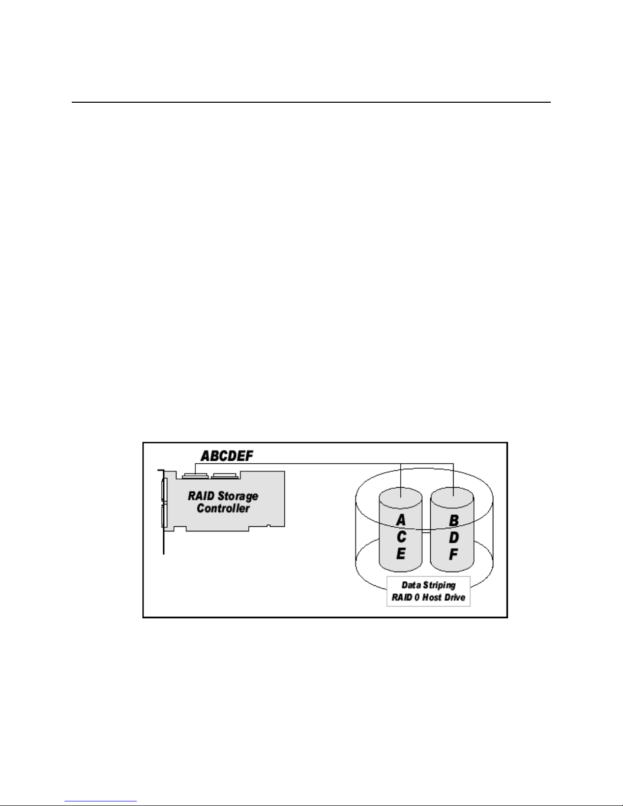
RAID 0 - Data Striping
Data blocks are split into stripes based on the adjusted stripe size (for example, 128 KB) and the
number of hard drives. Each stripe is stored on a separate hard drive. Significant improvement of
the data throughput is achieved using this RAID level, especially with sequential read and write.
RAID 0 (Figure 1) includes no redundancy. When one hard drive fails, all data is lost. RAID 0
requires a minimum of two disks.
Figure 1. RAID 0 – Data Striping
13
Page 14
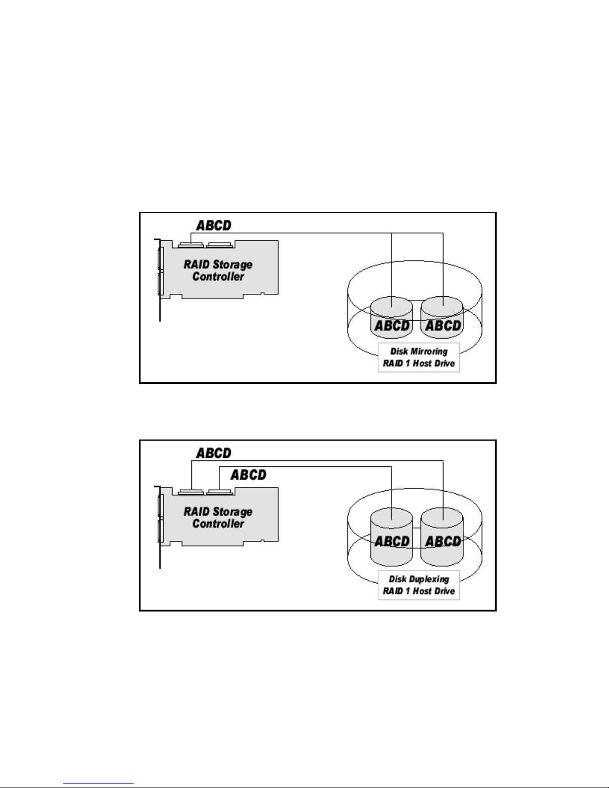
RAID 1 - Disk Mirroring/Dis k Duplexing
All data is stored twice on two identical hard drives. When one hard drive fails, all data is
immediately available on the other without any impact on performance and data integrity.
With Disk Mirroring (Figure 2) two hard drives are mirrored on one I/O channel. If each hard drive
is connected to a separate I/O channel, it is called Disk Duplexing (Figure 3).
RAID 1 represents an easy and highly efficient solution for data security and system availability. It
is especially suitable for installations that are not too large (the available capacity is only half of the
installed capacity). RAID 1 requires a minimum of two disks.
Figure 2. RAID 1 – Disk Mirroring
Figure 3. RAID 1 – Disk Duplexing
14 Intel RAID Controller SRCU32 User’s Gu ide
Page 15
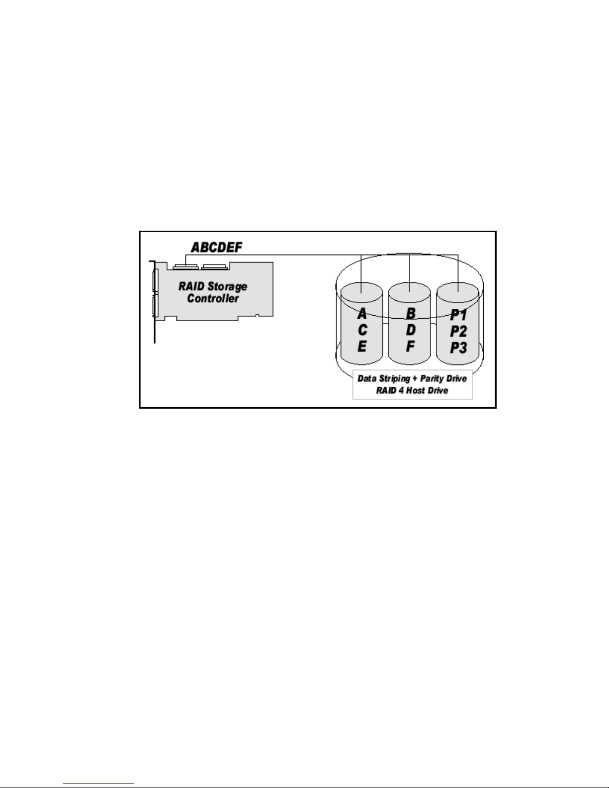
RAID 4 - Data Striping with a Dedicated Parity Drive
RAID 4 (Figure 4) works in the same way as RAID 0. The data is striped across the hard drives
and the controller calculates redundancy data (parity information) that is stored on a separate hard
drive (P1, P2). Should one hard drive fail, all data remains fully available. Missing data is
recalculated from existing data and parity information.
Unlike in RAID 1 only the capacity of one hard drive is needed for redundancy. For example, in a
RAID 4 disk array with five hard drives, 80% of the installed hard drive capacity is available as
user capacity, only 20% is used for redundancy. In systems with many small data blocks, the parity
hard drive becomes a throughput bottleneck. With large data blocks, RAID 4 shows significantly
improved performance. RAID 4 requires a minimum of three disks.
Figure 4. RAID 4
RAID 5 - Data Striping with Striped Parity
Unlike RAID 4, the parity data in a RAID 5 disk array are striped across all hard drives (Figure 5).
The RAID 5 disk array delivers a balanced throughput. Even with small data blocks, which are
very likely in a multi-tasking and multi-user environment, the response time is very good. RAID 5
offers the same level of security as RAID 4. When one hard drive fails, all data is still fully
available. Missing data is recalculated from the existing data and parity information. RAID 4 and
RAID 5 are particularly suitable for systems with medium to large capacity requirements, due to
their efficient ratio of installed and available capacity. RAID 5 requires a minimum of three disks.
Introduction and General Information 15
Page 16
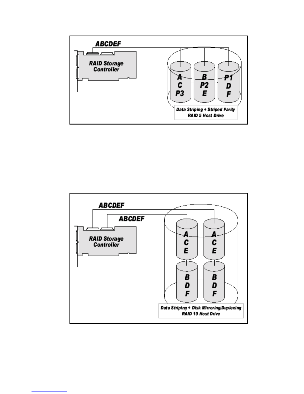
Figure 5. RAID 5
RAID 10 - Combination of RAID 1 and RAID 0
RAID 10 is a combination of RAID 0 (Performance) and RAID 1 (Data Security). Unlike RAID 4
and RAID 5, there is no need to calculate parity information. RAID 10 disk arrays offer good
performance and data security (Figure 6). As in RAID 0, optimum performance is achieved in
highly sequential load situations. Identical to RAID 1, 50% of the installed capacity is lost through
redundancy. RAID 10 requires a minimum of four disks.
16 Intel RAID Controller SRCU32 User’s Gu ide
Figure 6. RAID 10
Page 17

Chaining
The Intel RAID Controller SRCU32 firmware supports Drive Chaining (also referred to as Disk
Spanning). Drive Chaining is the process of linking several individual drives to form a large single
drive. Chaining is only available after having selected two or more drives in the Storage Console
(StorCon) or Storage Console Plus (StorCon+). Chaining is an inexpensive method to obtain a
large logical unit from many smaller hard drives.
WARNING
Disk Chaining does not offer any form of data protection and can result in loss of data. It is
therefore recommended not to use logical drives of the type chain as components of array drives.
Configuring a Chaining Set Using StorCon
1. Select “Create New Host Drive.”
2. Select two or more drives.
3. Select “Chaining.”
Configuring a Chaining Set Using StorCon+
1. Click the “New host drive” icon.
2. Select “Configuration,” “Host Drive,” and “Create New.” A new host drive window appears.
3. Select a drive(s) using <Shift> and arrow keys. Chaining is grayed out before selecting two
drives and is available after selecting two drives.
4. Select “Chaining” and press <Enter>.
The System will configure the chain set that is now a logical drive.
Introduction and General Information 17
Page 18

Levels of Drive Hierarchy Within the Intel® RAID
Controller SRCU32 Firmware
The Intel® RAID Controller SRCU32 firmware is based on four fundamental levels of hierarchy.
Each level has its own drives (components). The basic rule is to build up a drive on a given level of
hierarchy. The drives of the next lower level of hierarchy are used as components.
Level 1
Physical drives are hard drives and removable hard drives. Some Magneto Optical (MO) drives are
located on the lowest level. Physical drives are the basic components of all “drive constructions.”
However, before they can be used by the firmware, these hard drives must be “prepared” through a
procedure called initialization. During this initialization each hard drive receives information,
which allows an univocal identification even if the SCSI ID or the controller is changed. For
reasons of data coherency, this information is extremely important for any drive construction
consisting of more than one physical drive.
Level 2
On the next higher level are the logical drives. Logical drives are introduced to obtain full
independence of the physical coordinates of a physical device. This is necessary to easily change
the Intel RAID Controller SRCU32 and the channels, IDs, without loosing the data and the
information on a specific disk array.
Level 3
On this level of hierarchy, the firmware forms the array drives. Depending on the firmware
installed an array drive can be:
• Single Disks: one disk or a JBOD (just a bunch of drives)
• Chaining sets (concatenation of several hard drives)
• RAID 0 array drives
• RAID 1 array drives, RAID 1 array drives plus a hot fix drive
• RAID 4 array drives, RAID 4 array drives plus a hot fix drive
• RAID 5 array drives, RAID 5 array drives plus a hot fix drive
• RAID 10 array drives, RAID 10 array drives plus a hot fix drive
18 Intel RAID Controller SRCU32 User’s Gu ide
Page 19

Level 4
On level 4, the firmware forms the host drives. Only these drives can be accessed by the host
operating system of the computer. The firmware automatically transforms each newly installed
logical drive and array drive into a host drive. This host drive is then assigned a host drive number
which is identical to its logical drive or array drive number.
The firmware is capable of running several kinds of host drives at the same time. For example, in
Windows
is a single hard drive. On this level the user may split an existing array drive into several host
drives.
After a capacity expansion of a given array drive the added capacity appears as a new host drive on
this level. It can be either used as a separate host drive, or merged with the first host drive of the
array drive. Within StorCon, each level of hierarchy has its own menu:
Level 1 - Configure Physical Devices
Level 2 - Configure Logical Drives
Level 3 - Configure Array Drives
†
2000, drive C is a RAID 5 type host drive (consisting of five SCSI hard drives), drive D
Level 4 - Configure Host Drives
Generally, each installation procedure passes through these four menus, starting with level 1.
Installation includes the initializing the physical drives, configuring the logical drives, configuring
the array drives (for example, RAID 0, 1, 4, 5, and 10) and configuring the host drives.
Transparency of Host Drives
The structure of the host drives installed with StorCon (see Chapter 7, Storage Console) is not
known to the operating system. For example, the operating system does not recognize that a given
host drive consists of a number of hard drives forming a disk array.
To the operating system this host drive simply appears as one single hard drive with the capacity of
the disk array. This complete transparency represents the easiest way to operate disk arrays under
the operating system. Neither operating system nor the PCI computer need to be involved in the
administration of these complex disk array configurations.
Introduction and General Information 19
Page 20

Using CD-ROMs, DATs, Tapes, etc.
A SCSI device that is not a SCSI hard drive or a removable hard drive, or that does not behave like
one, is called a Non-Direct Access Device. Such a device is not configured with StorCon and does
not become a logical drive or host drive. SCSI devices of this kind are either operated through the
Advanced SCSI programming Interface (ASPI) (MS-DOS
or are directly accessed from the operating system (UNIX
NOTE
✏
Hard disks and removable hard disks are called Direct Access Devices. However, there are some
Non-Direct Access Devices, for example, certain MO drive that can be operated just like removable
hard disks if they have been appropriately configured (for example, by changing their jumper
settings).
†
, Windows, Novell NetWare† or OS/2†),
†
, Windows NT†).
20 Intel RAID Controller SRCU32 User’s Gu ide
Page 21

2 Getting Started
What is the Intel RAID Controller SRCU32 Firmware?
We refer to firmware as the operating system that controls the Intel RAID Controller SRCU32 with
all of its functions and capabilities. The firmware exclusively runs on the Intel RAID Controller
SRCU32 and is stored in the Flash-RAM on the Intel RAID Controller SRCU32 PCB. The
controlling function is entirely independent of the PCI computer and the host operating system, and
does not drain computing power or time from the PCI computer. According to the system
requirements needed, the Intel RAID Controller SRCU32 is available with two firmware variants.
The firmware is either already installed on the controller upon delivery, or can be added as an
upgrade.
Unlike pure software solutions, for example, for Windows NT, the Intel RAID Controller SRCU32
is a pure hardware RAID solution. All Intel RAID Controllers are equipped with hardware that is
well suited for disk arrays. The Intel RAID Controller SRCU32 firmware uses this hardware with
efficiency and therefore allows you to configure disk arrays that do not load the host computer
(whereas all software-based RAID solutions more or less reduce the overall performance of the host
computer).
The basic concept of the Intel RAID Controller SRCU32 firmware is strictly modular, and
consequently, in its functioning it appears to the user as a unit construction system.
Standard Firmware
In addition to simple controlling functions regarding SCSI hard drives or removable hard drives,
this version of firmware supports disk chaining and array drive configuration (data striping
(RAID 0) and disk mirroring or duplexing (RAID 1)).
WARNING
Disk Chaining does not offer any form of data protection and can result in loss of data. It is
therefore recommended not to use logical drives of the type chain as components of array drives.
21
Page 22

RAID Hardware Installation and Setup
NOTE
✏
The Intel RAID Controller SRCU32 will work in a 32-bit, 33 or 64 MHz PCI slot; however, a 64-bit
66 MHz slot is recommended for maximum performance.
Minimum Hardware Requirements
• Computer with CD-ROM drive (not attached to the Intel RAID Controller SRCU32).
Computer must be on the supported hardware list. For a supported list refer to:
http://support.intel.com/support/motherboards/server/
• One available PCI slot. See Note above.
• PCI 2.2 compliant System BIOS.
• SCSI hard drive(s) (the minimum required to meet the desired RAID level).
Installing and Removing the SDRAM
Installing the SDRAM
1. With clips A1 and A2 (see Figure 7) in the open position (position 2), insert the DIMM into the
DIMM connector (the DIMM and connector are keyed to ensure proper insertion).
CAUTION
Align the DIMM carefully to prevent damaging the conductor pads on the DIMM orthe
connector. Apply firm pressure but do not force.
2. With the thumbs positioned on each end of the DIMM and two fingers on the DIMM
connector, press the thumb and fingers firmly together until the DIMM clips snap into the close
position (position 1).
22 Intel RAID Controller SRCU32 User’s Gu ide
Page 23
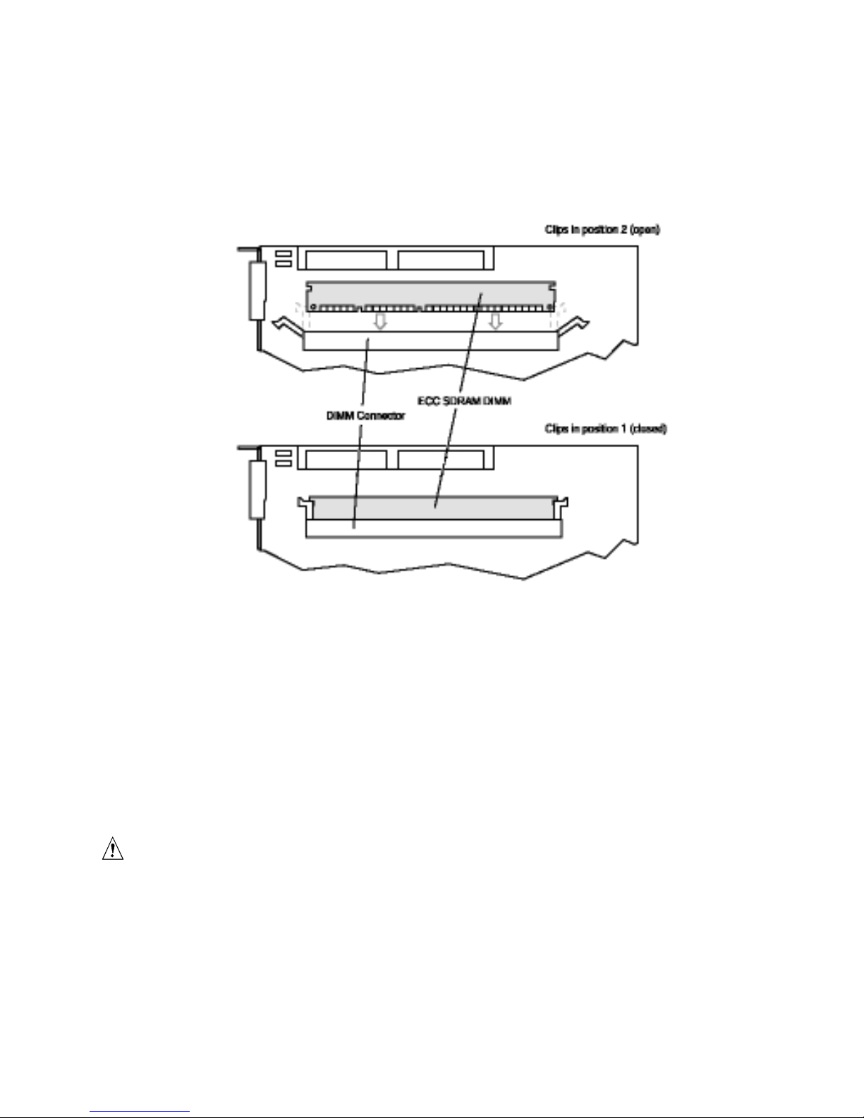
Removing the SDRAM
1. With the thumbs on the DIMM clips, swing the clips from the close position to the open
position.
2. Grasp the corners of the DIMM with both hands and firmly pull from the DIMM connector.
Figure 7. Installing the SDRAM
Install the Intel RAID Controller SRCU32 in the Intel®
Server Board
The RAID firmware has already been programmed into the memory. Prior to installing the Intel
RAID Controller SRCU32 into the computer, an approved memory module must be installed in the
controller. For a list of approved memory modules refer to:
http://support.intel.com/support/motherboards/server/
CAUTION
Contact the RAID vendor for a list of approved memory modules.
Getting Started 23
Page 24

WARNING
SHOCK HAZARDS may be present inside the unit in which this card is being installed.
Disconnect all power cords to the unit before removal of any covers. Follow the warnings noted
in the computer’s user or service manual before installing this board. ONLY after all the covers
are reinstalled should you reattach the power cords and power up the unit for the software
installation and use.
NOTE
✏
Take precautions to prevent electrostatic discharge (ESD) damage before handling the Intel RAID
Controller SRCU32.
Install the Intel RAID Controller SRCU32 into an available PCI slot. Refer to the board
documentation for details.
1. Shut down and power-off the computer system.
2. Disconnect power cord(s) and remove the system cover.
3. Insert the Intel RAID controller into an available PCI slot.
4. Connect one end of the SCSI cable to the internal (68 pin) or external (VHDCI) SCSI
connector located on the SRCU32 Controller. Connect the other end of the SCSI cable to the
SCSI drives or drive enclosure.
5. Replace the system cover; reconnect power cord(s).
Programming the FLASH Memory
The Intel RAID Controller SRCU32 normally comes ready to be immediately installed into the
computer server board. However, you may need to reprogram the RAID Firmware that’s located in
the flash memory of the Intel RAID Controller SRCU32. Refer to section 11 Appendix Firmware
Update for a normal reprogram of the firmware.
SCSI Termination
Termination
Termination is a commonly overlooked requirement when connecting SCSI devices together.
When these devices are connected together, the resulting set of devices is typically referred to as a
SCSI bus. SCSI devices such as hard drives and tape drives must be terminated if they are the last
physical devices at either end of the SCSI bus (if nothing else is actively terminating the end of the
bus such as a terminator or backplane). If a device is inserted into the middle of the SCSI bus, then
it (the device itself) should not be terminated. Only terminate each end of the bus.
24 Intel RAID Controller SRCU32 User’s Gu ide
Page 25
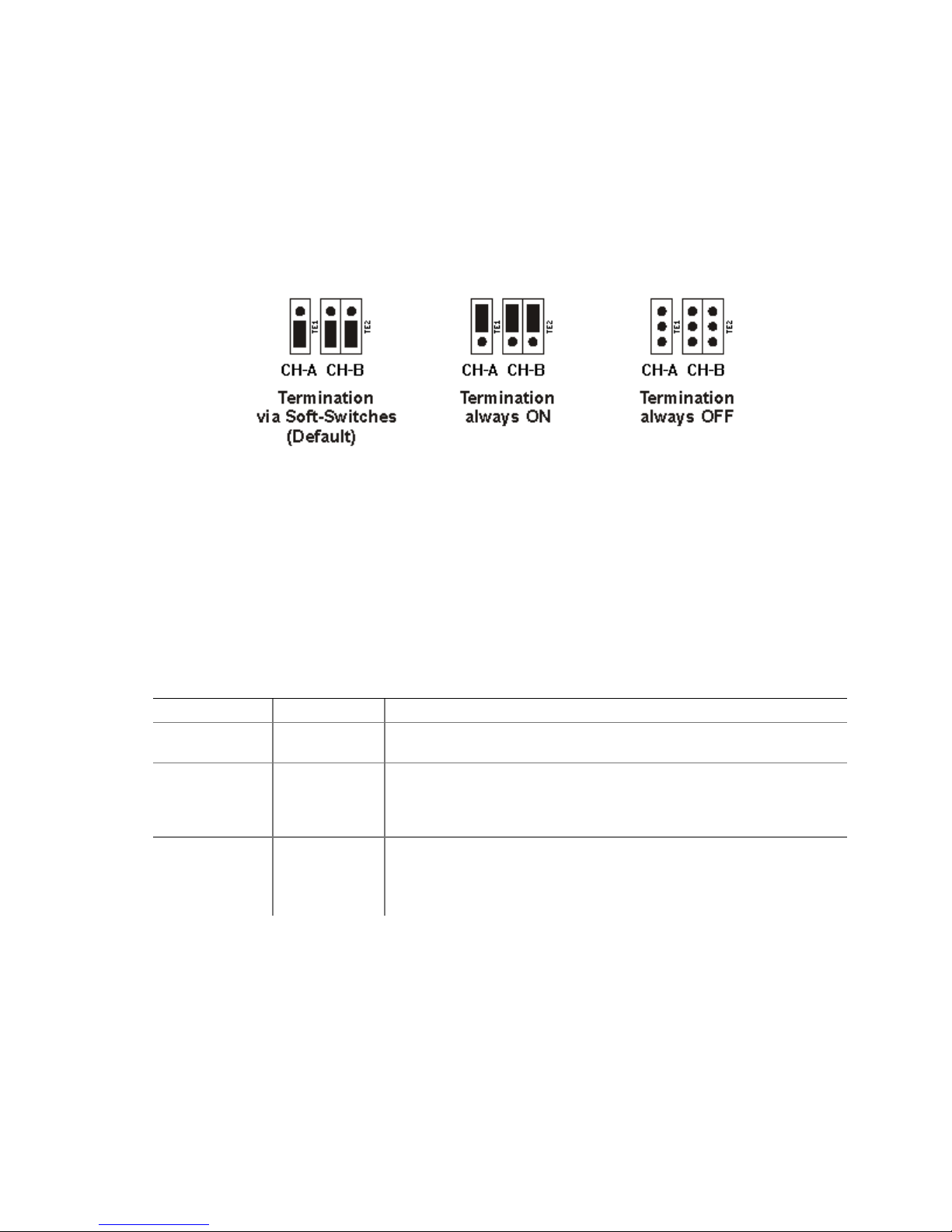
Setting the Termination Mode of the Intel RAID Controller SRCU32
The onboard termination of the RAID controller can be changed within Storage Console. The
default setting is "Auto" (jumpers in ‘Soft-Switch mode). In this mode, the controller automatically
activates/ deactivates termination based on cable connection (if internal and external connectors are
used of a specific channel then the termination is off, otherwise on). "On", "Off" turns the
termination on or off regardless of the connected cables. In addition to the "soft-switch" jumper
setting, termination jumpers force termination always ON or OFF - no matter of the software
settings or cables detected.
Configurable SCSI Parameters
When a SCSI hard drive is initialized the first time by the RAID controller, its SCSI parameters are
automatically set to their optimal settings. Manual configuration is not required. However, the
RAID controller allows for the custom configuration of several SCSI parameters on a hard
drive-by-hard drive basis. There are several settings that can be configured by using the Storage
Console menu Advanced Setup!Configure Physical Devices!Select Physical Drive !SCSI
Parameter/Initialize. Most settings are set automatically and cannot be configured manually. See
the following table.
Table 1. Hard Drive SCSI Parameters
Parameter Setting/Value Description
Synch. Transfer Not
Configurable
Synch. Transfer
Rate
Disconnect Not
Not
Configurable
Configurable
This setting, when enabled, allows the controller to operate in
synchronous transfer mode.
Allows for the setting of the speed for the SCSI hard drives (160 MB/sec
for U160 drives). No matter the setting, the SCSI bus will negotiate the
fastest speed up to this setting. Lowering the setting will force the hard
drive to transfer at the lower speed.
Enabling this setting allows for the hard drive to disconnect from the
SCSI bus when it’s not participating in a transfer. This allows for
optimal bus utilization by all devices on the bus.
(continued)
Getting Started 25
Page 26
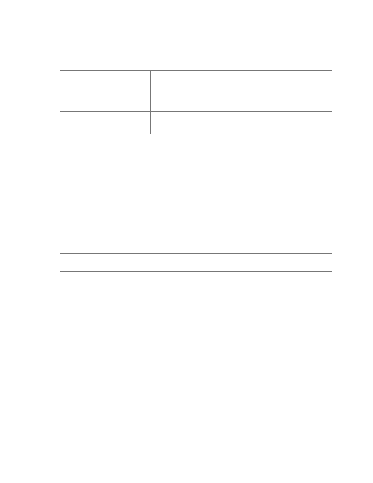
Table 1. Hard Drive SCSI Parameters (continued)
Parameter Setting/Value Description
Tagged Queues Not
Configurable
Disk Read and
Write Cache
Domain
Validation
On / Off For performance reasons, the Read Ahead and Write cache of the hard
Not
Configurable
When enabled, this feature allows the SCSI hard drive to execute more
than one command at a time.
drives should always be on.
Using the <F4> key while in this menu accesses this parameter. When
Domain Validation is set to On, Domain validation allows for a cyclical
check of the correct data transfer at a given rate.
Choosing a Configuration
How Many Hard Drives Should Be Integrated Into the Disk Array?
The number of physical drives the Intel RAID Controller SRCU32 can run determines the
maximum number of physical drives in a disk array. The minimum number of hard drives required
for any array depends of the RAID level you wish to realize. The desired usable disk space of the
disk array as well as the issues discussed in the following sections (What Level of Redundancy is
Needed and Are Hot Fix Drives Needed) have a direct impact on the number of physical hard
drives needed for an array.
Table 2. RAID Level, Array Type, and Hard Drive Requirements
RAID Level
RAID 0 Data Striping 2
RAID 1 Disk Mirroring 2
RAID 4 Data Striping with Parity Drive 3
RAID 5 Data Striping with Striped Parity 3
RAID 10 Data Striping and Mirroring 4
Disk Array Type
Minimum Number of
Hard Drives Required
What Level of Redundancy is Needed?
RAID 0 (data striping) provides no redundancy but has high data throughput. With RAID 1
(disk mirroring) the data is 100% redundant because it is mirrored on other SCSI hard drives.
RAID 1 provides the highest level of redundancy, but is also the most expensive solution. A
combination of RAID levels 0 and 1 is RAID 10. Two RAID 0 stripe sets are mirrored. If one
drive fails, the data is available on the mirrored drive.
With RAID 4 (data striping with a dedicated parity drive) and RAID 5 (data striping with parity
striped across all RAID disks), parity information is calculated from the data with a simple
mathematical operation (eXclusive OR, XOR), and stored either on one dedicated drive (RAID 4)
or to all drives (RAID 5). Should one drive fail, the data of the defective drive can be reconstructed
using the remaining user data and the previously calculated parity data. RAID levels 4, 5 and 10
can tolerate the failure of one drive just as RAID 1, however RAID 4, RAID 5, or RAID 10 are less
expensive because of their efficient ratio of available to installed capacity.
26 Intel RAID Controller SRCU32 User’s Gu ide
Page 27
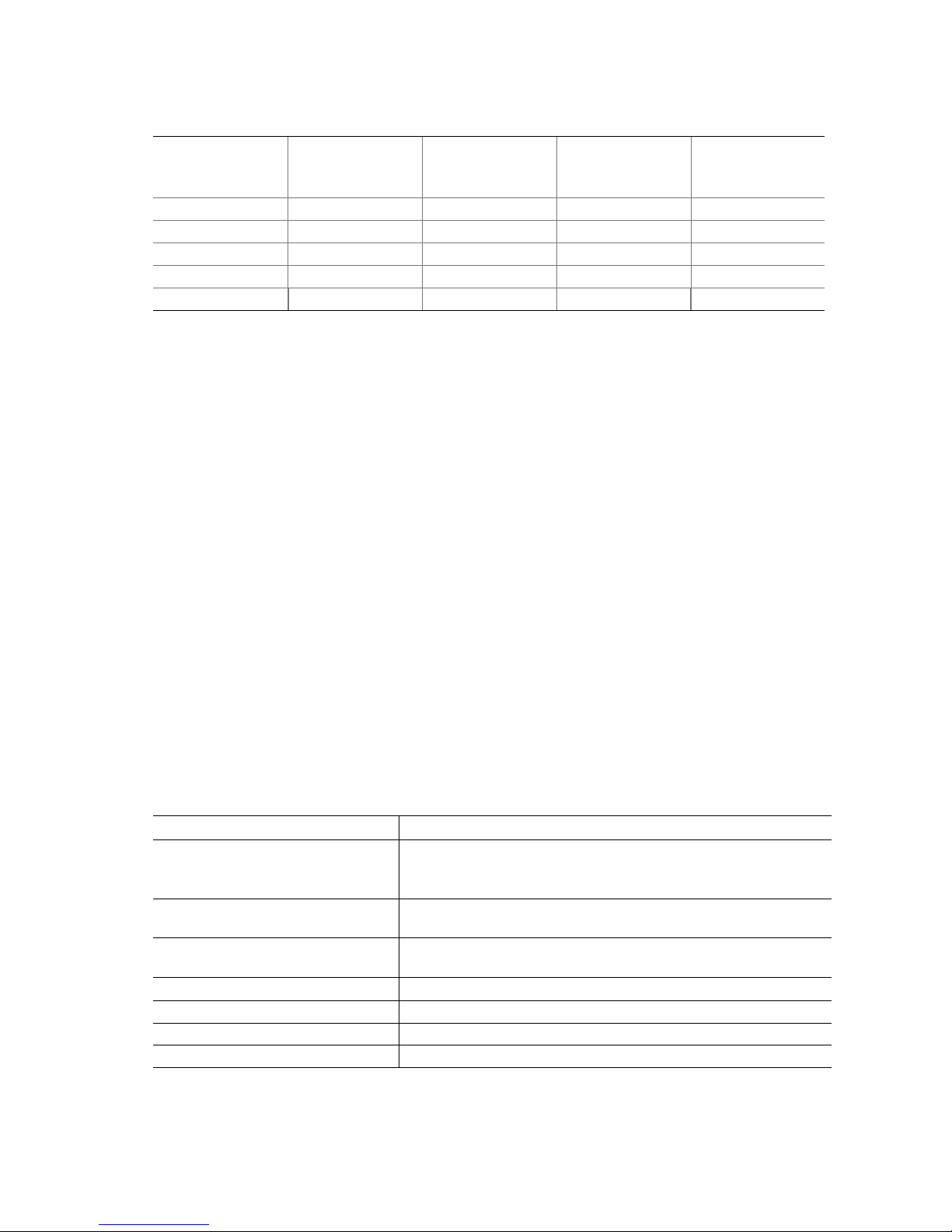
Table 3. RAID Level, Hard Drives, and Usable Storage Capacity
RAID Level
RAID 0 2 GB 3 GB 4 GB 5 GB
RAID 1 1 GB 1 GB 1 GB 1 GB
RAID 4 NA 2 GB 3 GB 4 GB
RAID 5 NA 2 GB 3 GB 4 GB
RAID 10 NA NA 2 GB NA
* Each hard drive is assumed to have 1 GB capacity.
Available
Capacity with
2 Hard Drives*
Available
Capacity with
3 Hard Drives*
Available
Capacity with
4 Hard Drives*
Available
Capacity with
5 Hard Drives*
Are Hot Fix Drives Needed?
Assume that one of the hard drives of the RAID 5 disk array fails (Hot Fix drives are available with
RAID 1, 4, 5, and 10 arrays). The disk array is without redundancy. Time Without Redundancy
(TWR) starts to run. Any unnecessary prolongation of the TWR (the time required to get a
replacement drive, or because you did not immediately recognize the failure) increases the risk of
data loss that will occur should a second drive fail. Therefore, redundancy should be restored as
soon as possible and in an automated manner. Integrating a Hot Fix drive (also referred to as hot
spare) as an immediately available and auto-replacing drive is the most effective way to keep the
TWR as short as possible. Only a Hot Fix drive can ensure optimal disk array security and constant
data availability.
Using a Hot Fix drive is not compulsory. If you control the disk array at regular intervals and
immediately replace a defective drive (by shutting down the system or hot-plugging), you can
operate the system without a Hot Fix drive.
Intel RAID Controller Hardware Features
This section provides a summary of the key features, configuration options and support interface
technology supported by the IIR controller.
Architecture Features (HW)
Table 4. Hardware Architecture
Component Feature
I/O Microprocessor The 80303 uses the 100MHz Intel 80960JT-100 core with a
100MHz/64-bit internal bus
800MB/sec,
Cache Memory The SRCU32 supports up to 256MB of 64-bit ECC SDRAM
operating at 100MHz. Memory is expandable to 64, 128, or 256MB.
Flash Memory 3.3v, 16Mb (2MB) flash memory chip is used to store the RAID
firmware
I/O interface (PCI) PCI 2.2 compliant, universally keyed for 3.3 and 5 volt PCI slots
PCI Transfer Rate 528MB/sec (Burst)
PCI Signaling 5 or 3.3 volt
SCSI Controller: LSI SYM53C1010 Dual channel Ultra160
to and from the internal IOP peripherals.
with an internal throughput of up to
Getting Started 27
Page 28

Environmental Characteristics
Table 5. Environmental Specifications
Attribute Condition
Thermal: Non-Operating -10
Humidity: Non-Operating 20% to 75% Relative Humidity, non-condensing
Operating Temperature & Voltage
Margin
Form Factor (physical dimensions) Height: 98 mm (3.86 inches)
Weight .35 kg (.77 lb)
o
C (Celsius) to 60o C
o
0
C to 55o C +/- 5% Vcc
Length: 200 mm (7.87 inches)
Hard Drive Connectivity (SCSI Specifics)
The RAID adapter supports up to 15 SCSI devices per SCSI channel. It supports up to 15 hard disk
drives (or 14 hard disks drives if one of the SCSI ID’s is occupied by a SAF-TE processor) per
channel of the SCSI controller (30 disk drives total for the dual channel SRCU32 controller).
Supported Hard Drive Technology
The IIR controller supports both Single-ended (SE) and Low Voltage Differential (LVD) devices
but it is recommended that you use only one type of drive technology (SE or LVD) on any one
channel at a time.
The IIR controller supports single-ended drives which operate at up to 40MB/sec depending upon
the speed of the drives attached.
The IIR controller supports Ultra-2 LVD SCSI devices operating at up to 80MB/sec and Ultra160
LVD SCSI devices operating at up to 160MB/sec.
NOTE
✏
If both SE and LVD devices are attached to the same channel/bus, the entire bus will operate at the
single-ended speed of the slowest device. See Table 6 for the maximum cable length distances that
apply to each mode.
The IIR controller is designed to use Ultra160 SCSI hard drives and is backward compatible with
older SCSI hard drive specifications. See Table 6 for the SCSI standards supported.
28 Intel RAID Controller SRCU32 User’s Gu ide
Page 29

Table 6. SCSI Drive Standards
SCSI Drive
Standard
Single-Ended LVD
SCSI-1 (2)
Fast SCSI (2)
Fast Wide SCSI
Ultra SCSI (2)
Ultra SCSI (2)
Wide Ultra SCSI
Wide Ultra SCSI
Wide Ultra SCSI
Ultra2 SCSI (2, 4)
Wide Ultra2 (4)
Ultra160 (Ultra3)
Notes:
1. May be exceeded in Point-to-Point and engineered specific applications.
2. Use of the word "Narrow", preceding SCSI, Ultra SCSI, or Ultra2 SCSI (for example, Narrow SCSI) is optional.
3. LVD was not defined in the original SCSI standards for this speed. If all devices on the bus support LVD, then
12-meters operation is possible at this speed. However, if any device on the bus is singled-ended only, then the
entire bus switches to single-ended mode and the distances in the single-ended column apply.
4. Single-ended is not defined for speeds beyond Ultra.
After Ultra2 all new speeds are wide only.
Speed
(MB/Sec)
5 8 6
10 8 3
20 16 3
20 8 1.5
20 8 3 N/A 4
40 16 N/A
40 16 1.5 N/A 8
40 16 3 N/A 4
40 8
80 16
160 16
Bus Width
(Bits)
Maximum Cable Length (meters) (1) Adapter Maximum
(3)
(3)
(3)
(3)
(3)
(4)
(4)
(4)
12 8
12 16
12 16
Devices per SCSI Channel
8
8
16
8
16
Support for Non-Hard-Disk-Drive SCSI Devices (Non-DirectAccess Devices)
The RAID controller will pass through to the host operating system direct access to nondirectaccess SCSI devices that are connected to a SCSI bus (channel) of the RAID controller. The RAID
controller passes through all control of these devices to the host operating system.
Types of supported non-Direct-Access SCSI devices (this does not cover specific vendors and
models):
• SAF-TE Processors
• Tape Devices
• CD-ROMs
Getting Started 29
Page 30

Array Roaming Compatibility
Array Roaming allows the user the ability to move a complete RAID array from one computer system
to another computer system and preserve the RAID configuration information and user data on that
RAID array. Compatible RAID controllers must control the RAID subsystems of the two computer
systems (see list of compatible controllers in this section). The transferred RAID array may be brought
online while the target server continues to run if the hard disk drives and disk enclosure support hotplug capabilities. The hard disk drives are not required to have the same SCSI ID in the target system
that they did in the original system that they are removed from. The RAID array drive that is being
roamed must not be of type Private. This includes all non-private host, array, and logical drives.
WARNING
The SRCU32 adapter, with firmware 2.33.xx, is not compatible with some previous versions of IIR
RAID FW running on IIR controllers. Only the versions listed below are compatible. Do not
attempt RAID Array Drive Roaming between RAID controllers that are not compatible with the
SRCU32 adapter. Unpredictable behavior may include, but is not limited to, data loss or
corruption.
Compatible adapters inc lud e:
• SRCU31 - Firmware version 6.2.32.xx (the 6 will not show on boot)
• SRCU31L - Firmware version 6.2.32.xx (the 6 will not show on boot)
• SRCU32 - Firmware version 2.33.xx
• SRCMR - Firmware version 2.32.xx
NOTE
✏
Compatibility refers only to how data and RAID configuration information are written to the hard
disks. Compatible adapters have the same data file format.
Number of Supported Devices
The Intel RAID Controller SRCU32 supports up to 15 different SCSI devices (single hard drives,
drive enclosures, controllers, CD-ROM’s, tapes, etc). In certain configurations, this number is
reduced.
Example: Up to 14 SCSI devices if a SAF-TE processor occupies one of the SCSI ID’s.
SCSI Connectors
The Intel RAID Controller SRCU32 includes two internal SCSI-3 Ultra Wide 68-pin connectors
and two external VHDCI (Very High Density Connector Interface) 68-pin connectors. Each
connector can be fully populated with up to 15 SCSI devices (not to exceed an additive total of
15 devices per channel when using both he internal and external connector for the channel) as long
as cable length limitations for each segment are not exceeded.
30 Intel RAID Controller SRCU32 User’s Gu ide
Page 31

LED Indicators
There are a number of LED indicators on the RAID controller that indicate the various modes
and/or states of the controller.
Function Check
Indicates the activity on the controller. See Table 7 for detail.
Table 7. Function Check
LED Function
A Indicates activity on SCSI channel A
B Indicates activity on SCSI channel B
T Indicates Bus Master DMA transfers (the brighter the light, the more DMA’s)
S When system is powered, indicates that controller is online (i.e. installed correctly)
Channel Mode
A yellow LED for each Ultra160 SCSI channel, indicates the current SCSI mode of the
corresponding channel. If the LED is lit, the Ultra160 SCSI channel is operating in Low Voltage
Differential (LVD) mode. If the LED is not lit, this channel is operating in Single-Ended (SE)
mode.
PCI Bus Clock
Indicates the clock speed of the PCI Bus interface. If the LED is not lit, the bus speed in 33MHz.
If the LED is lit, the bus speed is 66MHz.
Jumpers
In addition to the Termination Jumpers (described earlier in this document), the IIR controller has a
series of jumpers that allow for specif ic conf ig ura tion o f the contro l ler.
Getting Started 31
Page 32

External LED Connectors
The IIR Controller has a 6 pin header to allow for connection of additional LEDs. An LED
connected with header A lights up whenever there is activity on SCSI channel A. The same applies
for header B. An LED connected with the SUM header lights up whenever there is activity on any
of the two SCSI channels A and B. See Figure 8 for details.
Figure 8. External LED Connectors
Terminator Power
Determines whether termination power (per channel) is supplied by the controller. The Default is
ON for both channels (both jumpers set).
Acoustical Alar m
An acoustical (audible) alarm is present on the RAID controller to indicate any of the following
events:
• State of controller upon boot-up
• Change in state of array
• Change controller environmental status (during normal operation)
• Hardware failure
If the cause of the event is resolved and/or removed, the audible alarm will cease. The audible
alarm can also be turned off manually through StorCon or StorCon plus. If the audible alarm is
silenced via management tools, it will only be disabled for the current event and will be ready to
sound again at the next event.
Silencing the Acoustical Alarm in StorCon
An option is available in StorCon under Advanced Setup ! Configure Controller, press <F4> to
silence alarm. The <F4> option is available only if the alarm has been activated.
Silencing the Acoustical Alarm in StorCon+
To silence the alarm in StorCon+, in the “Physical Configuration” view, right-click on the icon for
the controller that requires alarm deactivation. Click on “Silence” to deactivate the alarm. If the
alarm has not been activated, the “Silence” option will be grayed out and unavailable.
32 Intel RAID Controller SRCU32 User’s Gu ide
Page 33

Compatible Intel RAID Controllers
This Intel RAID Controller SRCU32 is compatible with other Intel RAID Controllers SRCU32 and
SRCMR and allows for array roaming.
NOTE
✏
Compatible refers to the ability of the In tel RAID Con t roller SRCU 32 to read the RA ID
configuration information located on hard drives that are members of RAID Arrays that have been
created on compatible adapters. Thus RAID Arrays created on compatible adapters are
interchangeable between the adapters (Array Roaming).
Optional RAID Features Implemented in the Intel RAID
Controller SRCU32
Adapter Device Limitation Support
• RAID Arrays contain
Host Drives (at least 1 and up to 16 maximum)
Hard Drives up to 30 maximum spanning both channels (all host drives that are created on
an existing RAID Array will have their capacity evenly distributed across all member hard
drives of the RAID Array)
• Host Drives
Can span across both channels
Can not span across RAID Arrays
Table 8. Disk, Volume, and Array Limitations
Adapter Device Limitations
Per Adapter Per RAID Channel Per RAID Array Per Host Drive
Max Min Max Min Max Min Max Min
Hard Drives
RAID Arrays
Host Drives
Note:
1. Each Host Drive can only be associated with one RAID Array.
2. To create a new RAID Array you must initially create a Host Drive selecting the hard drives (that are available
30 15 30 1 30
2
16 15 1
1
16 16 16 1
and not already members of a RAID Array) that you wish to be members of the new RAID Array.
PCI Hot Plug
The SRCU32 adapter supports PCI Hot Plug under the following OS’s:
• Windows 2000 Advanced Server SP2, Windows 2000 Server, Windows 2000 Professional
• NetWare 5.1 SP2a
This IIR controller supports the PCI Hot Plug functionality for the Hot Replacement of an adapter.
Hot Replacement assumes that the drivers for the adapter being replaced are already loaded.
Getting Started 33
Page 34

Operational States of an Intel RAID Controller SRCU32
Firmware Disk Array
Operational States for RAID 4/5
An array drive under the Intel RAID Controller SRCU32 firmware operating system can assume
seven different operational states: Idle, Ready, Fail, Build, Rebuild, Expand, and Error. Table 9
describes the operational states for RAID 4/5 while Figure 9 is the operational state diagram for
RAID 4/5 Table 10 describes additional operational states.
Table 9. Operational States for RAID 4/5
State Description
Idle State This state is characterized by the fact that the redundant information of the disk
array has never been entirely created. The disk array is in this state after its first
configuration and until you quit Storage Console (StorCon). Should an error occur
while the array is in the build state, the array returns to the Idle state (exception: if
during build state the dedicated drive of RAID 4 fails, the state changes to fail.
Build State After the disk array has been configured for the first time, it assumes the build state
as soon as you quit StorCon. While the array is in the Build state, redundancy
information is calculated and stored to the hard drives of the array.
Ready State The disk array is fully operational when in the Ready state. All redundant
information is present, that is, a hard drive can fail without impairing the
functionality of the disk array. This is the normal state of a disk array. The state
ready/expand indicates that the RAID level and/or capacity are currently
migrated/expanded.
Fail State The disk array changes to the fail state whenever a Logical Drive fails.
Redundancy information is still present, thus allowing the remaining hard drives to
continue working. This state should be eliminated as soon as possible by replacing
the defective hard drive. If a so-called Hot Fix drive has previously been assigned
to a disk array with StorCon, the controller will automatically replace the defective
drive and start the reconstruction of the data and the redundant information.
Therefore, under these circumstances the fail state is only temporary and will be
eliminated by the controller itself.
Rebuild State The disk array will assume this state after the automatic activation of a Hot Fix
drive or after a manual replacement is carried out with StorCon. The data and the
redundant information are reconstructed and stored to the new drive.
Expand State If the capacity or RAID level of an existing disk array is changed, the disk array
changes its state into expand. As soon as the expansion or migration is
completed, the state changes back to ready.
34 Intel RAID Controller SRCU32 User’s Gu ide
Page 35

Figure 9. Operational State Diagram for RAID 4/5
Getting Started 35
Page 36

Table 10. Additional Operational States
State Description
OK State The disk array is fully operational when in the OK state. All redundant
information is present, that is, a hard drive can fail without impairing the
functionality of the disk array. This is the normal state of a disk array.
Methods for Hard Drive Replacement
The Intel RAID Controller SRCU32 and the Intel RAID Controller SRCU32 firmware offer a
variety of methods to replace a defective hard drive. When to use them depends on the physical
environment of the server. With some servers the hard drives are mounted into the server
enclosure. They are not removable. With other servers there is an intelligent backplane (for
example, SAF-TE) and which hosts a number of hard drives with a Single Connector Attachment
(SCA). Another type of server uses the hard drive in a hot pluggable disk carrier. These carriers
are often unintelligent and do not communicate with the Intel RAID Controller SRCU32 or server,
though, they can display the hard drive’s temperature or the status of its built-in fan. The following
table contrasts the various hard drive replacement options.
Table 11. Hard Drive Replacement Options
Manual Hot Plug
Typical
Server
Environment
Low Cost.
Hard drives are physically
mounted in the server
enclosure and are not
removable.
Auto Hot Plug
Additional cost for external
enclosure, cables,
backplanes, etc.
Hard drives are removable in
an intelligent or
non-intelligent subsystem.
The subsystem complies
with one of the following
enclosure standards:
“SAF-TE” (SCSI Accessed
Fault Tolerant Enclosures)
“SES” (SCSI Enclosure
Services)
“Intelligent Fault Bus” (former
DEC™ fault bus)
Non-Intelligent subsystems
using hot pluggable disk
carriers.
Automatic Replacement
with Hot Fix Drive
Low cost.
High availability.
The Intel RAID Controller
SRCU32 has a spare drive
available at all times. Should
one hard drive of an array
fail, the spare drive (hot fix
drive) is automatically built
into the array.
continued
36 Intel RAID Controller SRCU32 User’s Gu ide
Page 37

Table 11. Hard Drive Replacement Options (continued)
Manual Hot Plug
Description StorCon or StorCon+ guides
the user to the point where a
new hard drive can be built
into the array drive.
Auto Hot Plug
The subsystem must be
configured with StorCon or
StorCon Plus, before the
auto hot plug can work.
Thereafter a hard drive can
just be pulled out and
plugged in, and the Intel
RAID Controller SRCU32
“knows” what to do. In
addition, SAF-TE and SES
report the enclosure status
(power supplies, fans,
temperature etc.) to the Intel
RAID Controller SRCU32
and the Intel RAID Controller
SRCU32 driver.
Automatic Replacement
with Hot Fix Drive
The hot fix drive is assigned
to an array drive. There are
two types of hot fix drives:
Private hot fix drive
(Available for one array drive
only)
Pool hot fix drive
(Several array drives share
this hot fix drive)
Intel RAID Controller SRCU32 Quick Start
This section is a quick start that can be used when installing the Intel RAID Controller SRCU32
†
using either Windows 2000 or Red Hat
information when using other operating systems, please refer to the chapters 3 through 10.
Make an OS Installation Diskette
1. Boot from the Intel RAID Controller SRCU32 Software CD.
2. Select “Create Diskettes.”
3. Create an operating system installation diskette.
Linux† 7.1. For more detailed instructions and to get
Getting Started 37
Page 38

Install the SDRAM
1. Insert the DIMM into the DIMM connector. Make sure the DIMM clips snap to the close
position. (Supported DIMMs are 64 MB to 256 MB ECC PC133 unbuffered SDRAM
memory).
Install the Intel RAID Controller SRCU32 in the Intel Server Board
Install the Intel RAID Controller SRCU32 into an available PCI slot. Refer to the board
documentation for details. The example below refers to the Intel SCB2 server board.
1. Shut down the computer system.
2. Turn the power off.
3. Insert the Intel RAID controller into an available PCI slot.
Use StorCon to Create a RAID Volume
1. Power on the system and press <Ctrl> + <G> when the screen below appears.
2. The following two messages will appear at the bottom of the screen:
“Intel (R) Storage Console to start after POST”
“Please wait to start Intel (R) Storage Console…”
3. When StorCon starts, it will display the Intel RAID Controller SRCU32 installed in the system.
Press <Enter> to select this controller.
38 Intel RAID Controller SRCU32 User’s Gu ide
Page 39

4. Select “Configure Host Drives” and press <Enter>.
5. Select “Create New Host Drive.” StorCon displays a list of “free” hard drives. These are
drives that do not belong to a logical host drive and can be used for new host drives.
6. Use the arrow keys and the space bar to select the number of hard drives that you want to be
part of the array (these hard drives become marked with an “*”). For this example, we used
four hard drives. Press <Enter>. Move the selection bar with the arrow keys from one entry to
another. To deselect a drive, highlight the drive with the selection bar and press the space bar.
Getting Started 39
Page 40

7. The “Choose Type” menu offers different host drive types. For this example, we select
“RAID 5 + Hot Fix” and press <Enter>.
8. For security reasons, you will be asked if you want to use the selected disk to create a host
drive. StorCon displays a warning that all data will be destroyed after confirmation. Confirm
the choice by pressing <Y>. StorCon creates a new host drive.
9. Enter the appropriate drive capacity and press <Enter>.
10. The new host drive is created. Press <F10> to refresh and begin the build process. Its status is
still “build,” since the Intel RAID Controller SRCU32 synchronizes both drives.
40 Intel RAID Controller SRCU32 User’s Gu ide
Page 41

NOTE
✏
The array build will continue as a background task. Exit StorCon, by pressing <ESC>, and the
array build will continue in the background after BIOS POST upon reboot. You can then proceed
with OS installation while the array continues the build process in the background.
11. When leaving StorCon, by pressing <ESC>, a progress window displays the estimated
completion time for the build process.
12. Upon successful completion of the build process, the disk array changes to Ready status.
Set the BIOS Boot Order
This step requires entering the system BIOS and setting the proper boot priority. This step may
differ from system to system. Refer to the system documentation for details. The example below
refers to the Intel
®
SCB2 server board.
1. During POST, press <F2> to enter the BIOS Setup Utility.
2. Navigate to the “Boot” menu, then access the “Boot Device Priority” submenu and set the
following order:
• Removable Devices
• ATAPI CD-ROM Drive
• Hard Drive
• Intel
®
Boot Agent
Getting Started 41
Page 42

3. Access the “Hard Drive” submenu and make sure the “[Legacy SCSI Option ROM]” is on the
top of the priority list.
✏ NOTE
In the “Hard Drive” submenu, “[Legacy SCSI Option ROM]” may have different wording.
4. Press <F10> to save the changes and exit. The system will reboot.
Install the Operating System (cho ose from Windows 2000 or
Red Hat Linux 7.1)
Installing Windows 2000
Install Windows 2000 Server:
IMPORTANT: When the blue setup screen first appears, hit <F6> key.
1. Boot the system with the Windows 2000 CD-ROM.
2. Press <F6> as soon as the first blue screen appears to bypass mass storage detection.
3. When prompted to specify a mass storage controller:
• Select “S” to specify additional storage devices.
• Insert the Windows 2000 Installation driver diskette.
• Press <Enter> to select the “Installation Driver” and continue with Windows installation.
42 Intel RAID Controller SRCU32 User’s Gu ide
Page 43

Install and Launch the StorCon and StorCon+ Utilities:
1. Insert the Intel RAID Controller SRCU32 Software CD.
2. Select “Install” and follow the on screen instructions to install the StorCon and StorCon+
utilities. (As necessary, refer to Chapter 7, Loading StorCon, for detailed instructions).
3. Launch the StorCon and/or StorCon+ utilities by clicking on the icons located on the desktop.
Installing Red Hat Linux 7.1
Install Red Hat Linux Server:
1. Boot the system with the Red Hat Linux CD-ROM.
2. At the install prompt, select “linux dd.”
3. When prompted, insert the Red Hat Linux driver diskette.
4. Continue with the Linux OS installation.
Install the Intel RAID Controller SRCU32 StorCon Monitoring Utility:
(As necessary, refer to Chapter 7, Loading StorCon, for detailed instructions).
1. Place the Intel RAID Controller SRCU32 CD-ROM in the CD-ROM drive and mount the
CD-ROM:
$ mount /dev/cdrom /mnt/cdrom
2. Copy the StorCon utility archive to /usr/sbin:
$ cp /mnt/cdrom/linux/install/storcon-2.02.gz /usr/sbin/storcon-2.02.gz
3. Unpack the archive file and rename:
$ gunzip –d /usr/sbin/storcon-2.02.gz
$ mv /usr/sbin/storcon-2.02 /usr/sbin/storcon
4. Launch the StorCon utility by typing “storcon” at any prompt.
5. Select the Linux interface to run the utility locally.
Getting Started 43
Page 44

Alternative Method to Creating an Intel RAID Controller
SRCU32 Installation Diskette
If you are unable to create the Intel RAID Controller SRCU32 installation diskette by booting from
the Intel RAID Controller SRCU32 CD, you can run the CD on a Windows system and create
drivers for any OS. Alternately, you can manually create these disks for the following operating
systems:
Windows NT†
1. Insert the RAID Software Suite CD-ROM into the CD-ROM drive.
2. Insert a blank floppy diskette in the drive.
3. Go to the directory, \windows\winnt\drivers\i386, and copy all files onto a floppy diskette.
Windows 2000
1. Insert the RAID Software Suite CD-ROM into the CD-ROM drive.
2. Insert a blank floppy diskette in the drive.
3. Go to the directory, \windows\win2000. In this directory you will find four files and two
directories. Copy all files and only the “winnt” directory onto the floppy diskette.
SCO UnixWare
1. Insert the RAID Software Suite CD-ROM and go to the “apps” folder.
2. Create a folder on the system hard drive and copy the “rawrite.exe” application to that folder.
3. Open the “UnixWare” folder on the CD-ROM, then open the “dskimg” folder.
4. Copy “unixw7.img” to the folder created in step 2.
5. Open the command window. From the command prompt, go to the folder created in step 2 and
type the following command: “rawrite.”
6. Enter the file name: “unixw7.img.”
7. When prompted to enter the name of the drive, type in the drive letter of the floppy drive (for
example, A:) and then insert a blank floppy diskette in the drive and follow the instructions on
the screen.
†
44 Intel RAID Controller SRCU32 User’s Gu ide
Page 45

How to Use Auto Hot Plug with SAF-TE
The Auto Hot Plug option of the Intel RAID Controller Software provides for the insertion of new
disks into a system. The way a new disk is used can be different depending on the conditions under
which it was inserted. If the system has a degraded array and a disk is hot plugged into the system,
the new disk will be used to rebuild the degraded array. If a system had a degraded array and used
one of the available hot fix disks to rebuild and then a disk was hot plugged, the new disk will
become a hot fix disk replacing the post of the one being used in the array.
Setting Up Auto Hot Plug
Enable SAF-TE on the enclosure.
NOTE
✏
It is possible to have auto hot plug without a SAF-TE enclosure, but that setup is completely
different from that described here.
The Intel RAID Controller SRCU32 configures devices in the SAF-TE enclosure. The controller
identifies drives as being connected to the SAF-TE backplane and responds appropriately to
requests by the SAF-TE device.
Verify the configuration in the Enclosure Slot Configuration menu.
1. Select the Configure Physical Devices while in the Advanced Setup mode.
2. Highlight the SAF-TE processor and press <Enter>.
3. Select the Enclosure Slot Configuration option.
4. The Enclosure Slots screen is displayed. It shows what drives have been identified in which
slots of the enclosure. Pressing <Enter> once configures the drives; drive information appears
on the page. Pressing <Enter> again removes the drive configuration information from the
page. All devices that are to be hot spare replaceable should have information in their
respective slots. The lack of drive configuration information indicates the absence of a hot
spare. Once the drives have been configured, they are auto hot spare ready.
Note that disks can only be replaced in positions that have been configured for a device. If
there is a degraded array on a controller, and a user plugs in a drive in one of the slots not in use
in the enclosure, the drive will not become available to the system.
If no disks in a volume (array) creation are configured, a message: “Do you want to configure
the selected disks for SAF-TE Auto Hot Plug? (Y/N)” appears. If even one disk of the intended
array is configured, this message will not appear. However, only the configured disks are auto
hot pluggable.
Getting Started 45
Page 46

Page 47

3 Installing Microsoft Windows NT or
Windows 2000
This section covers installation issues related to the Microsoft Windows NT and Windows 2000
operating systems. For a successful installation, study the Windows NT/2000 system manuals
thoroughly. The required Intel RAID Controller SRCU32 disks can be created from the Intel RAID
Controller SRCU32 system CD-ROM.
Operating System Installation Procedures
✏✏✏✏
NOTE
Begin the installation process in this chapter if you are installing the OS and Intel RAID Controller
SRCU32 or upgrading from the Windows NT OS (the OS is currently installed on a compatible
Intel RAID Controller SRCU32) to Windows 2000.
Your installation falls into one of two categories:
• Install the OS on either a RAID volume or single disk that is attached to and configured on the
Intel RAID Controller SRCU32 that you are installing,
OR
• Install the OS on either an IDE hard drive or a SCSI hard drive that is not attached to the Intel
RAID Controller SRCU32 that you are installing
Pre-Installation Requirements Checklist
This section identifies the minimum hardware and software required to successfully install the Intel
RAID Controller SRCU32 and the accompanying software suite.
Minimum Hardware Requirements
NOTE
✏
The Intel RAID Controller SRCU32 will work in a 32-bit, 33 or 64 MHz PCI slot; however, a 64-bit
66 MHz slot is recommended for maximum performance.
• Computer with CD-ROM drive (not attached to the Intel RAID Controller SRCU32).
Computer must be on the supported hardware list.
• One available PCI slot. See note above.
• PCI 2.2 compliant System BIOS.
• SCSI hard drive(s) (the minimum required to meet the desired RAID level).
47
Page 48

Minimum Software Requirements
Microsoft Windows 2000:
• RAID Software Suite CD-ROM
• 9 MB of free hard drive space (for the RAID Software Suite)
• Microsoft Windows 2000 Professional, Server or Advanced Server
• Intel RAID Controller SRCU32 Installation diskette (one blank high density floppy diskette
may be required to create the installation diskette)
Microsoft Windows NT 4.0:
• RAID Software Suite CD-ROM
• 9 MB of free hard drive space (for the RAID Software Suite)
• RAID Driver Installation diskette (one blank high density floppy diskette*
create the installation diske tte)
• Microsoft Windows NT 4.0 Workstation*, Server* or Server Enterprise Edition*
* Not supplied
may be required to
Installing an Operating System onto a RAID Volume or
Single Disk
If you do not have the Intel RAID Controller SRCU32 Installation dis ke tte fo r the opera ti ng system
that you are installing, create it before continuing. See Chapter 2 for instructions to create this disk.
Also refer to Chapter 2 for instructions to install the Intel RAID Controller SRCU32 and to set up a
RAID volume.
NOTE
✏
Prior to installing Windows NT, disable the Delayed Write Cache of the Intel RAID Controller
SRCU32.
CAUTION
To avoid this problem and prevent the risk of data corruption, the Delayed Write function of the
Intel RAID Controller SRCU32 cache must be disabled during the complete installation. To do so,
use the StorCon program. Choose Advanced Setup, Configure Controller, Controller Settings and
switch the Delayed Write function OFF. After having completed the Windows NT installation,
switch the Delayed Write function ON again.
When you do a warm boot by simultaneously pressing the <Ctrl> + <Alt> + <Del> keys, some PCI
server boards carry out a hard reset of the PCI bus. As a consequence, all expansion cards and
devices that are connected to the PCI bus, including the Intel RAID Controller SRCU32, are reset.
During the installation procedure of Windows NT this anomaly can cause the contents of the Intel
RAID Controller SRCU32 cache RAM to be deleted before the data can be written to the disk(s).
If this happens, the installation cannot be completed correctly. Such a warm boot automatically
takes place after a FAT partition is converted into a NTFS partition at the end of the Windows NT
installation procedure.
48 Intel RAID Controller SRCU32 User’s Gu ide
Page 49

Figure 10. Controller Settings
Windows 2000 / NT 4.0 Installation Procedures
This document, when referring to Windows 2000 and Windows NT, applies to the following
Windows operating systems unless otherwise noted:
• Windows 2000 Server, Advanced Server, and Professional
• Windows NT 4.0 Server, Enterprise Edition, Terminal Server Edition, and Workstation
Installing the OS
The following installation procedures highlight the Windows setup options that you must install
during OS installation to successfully prepare the operating system for the installation of the RAID
Software Suite.
Install the operating system software using one of the scenarios (boot diskettes or CD-ROM) below
that matches the installation m ethod.
NOTE
✏
For detailed Windows installation procedures, please consult the documentation that came with the
computer system or operating system.
Installing Windows Using the Installation Boot Diskettes:
1. During install let Windows detect the storage devices in the system. When device detection is
complete, press <S> to specify additional storage devices.
2. Select Other. Insert the Intel RAID Controller SRCU32 installation diskette for Windows into
the floppy drive, press <Enter>.
Installing Microsoft Windows NT or Windows 2000 49
Page 50

3. Intel RAID Controller SRCU32 is automatically selected. Press <Enter>.
4. Complete the text-based portion of the Windows installation procedures. Reboot and continue
with the GUI-based portion of the installation.
5. After the operating system is completely installed, go to Chapter 7, Loading StorCon to
complete the installati on.
Installing Windows Using the Bootable Windows CD-ROM:
1. Press <F6> as soon as the initial blue screen appears to ensure that the RAID Driver Installation
diskette can be loaded when specifying “Other.”
2. When device detection is complete, press <S> to specify additional storage devices.
3. Select “Other.” Insert the Intel RAID Controller SRCU32 Installation diskette for Windows
into the floppy drive. Press <Enter>.
4. Intel RAID Controller SRCU32 is automatically selected. Press <Enter>.
5. Complete the text-based portion of the Windows installation procedures. Reboot and continue
with the GUI-based portion of the installation.
6. After the operating system is completely installed, go to Chapter 7, Loading StorCon to
complete the installati on.
Installing an OS onto an IDE or SCSI Hard Drive Not Attached to the Intel RAID
Controller SRCU32
Install the Intel RAID Controller SRCU32:
1. Power-off the computer.
2. Disconnect all power cords.
3. Remove the computer case to expose the server board inside. Observe all warnings and
cautions documented with the computer system to avoid shock hazards.
4. Install the Intel RAID Controller SRCU32 into an available PCI slot.
5. Replace the computer case and reconnect power cords.
6. Go to the next section for the operating system to continue the installation.
Windows 2000 / NT 4.0 Installation Procedures
NOTE
✏
This document, when referring to Windows 2000 and Windows NT, applies to the following
Windows operating systems:
• Windows 2000 Server, Advanced Server, and Professional
• Windows NT 4.0 Server, Enterprise Edition, Terminal Server Edition, and Workstation
50 Intel RAID Controller SRCU32 User’s Gu ide
Page 51

Installing the Operating System
The following installation procedures highlight the Windows setup options that you must install to
successfully prepare the operating system for the installation of the RAID Software Suite.
NOTE
✏
For detailed Windows installation procedures, please consult the documentation that came with the
computer system or operating system.
Install the operating system software using one of the scenarios (boot diskettes or CD-ROM) below
that matches the installation m ethod.
Installing Windows with Installation Boot Diskettes
1. Boot from the Windows Installation diskettes to setup Windows.
2. Insert boot diskettes and power up the system.
3. During install let Windows detect the storage devices in the system.
4. When device detection is complete, if the hard drive controller is not detected and listed, press
<S> to specify additional storage devices and install the driver.
5. Continue with the Windows installation.
6. After the operating system is completely installed, go to Chapter 7, Loading StorCon to
complete the installati on.
Installing Windows Using the Bootable Windows CD-ROM
NOTE
✏✏✏✏
If the driver for the hard drive controller is on the Windows CD-ROM, then follow prompts and
continue at Chapter 7, Loading StorCon. If you are installing a driver that does not come with the
Windows installation CD-ROM, for example, the Intel RAID Controller SRCU32 driver created in
Chapter 2, then follow the procedure below.
1. Insert the CD-ROM and power up the system. If the drivers for the hard drive controller are
not on the bootable Windows CD-ROM, press <F6> as soon as the initial blue screen appears
to ensure that the driver diskette can be loaded.
2. When device detection is complete, press <S> to specify additional storage devices and then
select “Other.” Insert the Intel RAID Controller SRCU32 diskette into the floppy drive and
continue the installation (see the next section ).
Installing Microsoft Windows NT or Windows 2000 51
Page 52

Upgrading an OS (Windows NT 4.0 to Windows 2000) that is Currently Installed on
a RAID Volume or Single Disk
Before you Begin:
Ensure that the OS is installed on an Intel RAID Controller SRCU32 that is compatible with the
new OS and/or RAID Software Suite that you are about to install. If it is not compatible, then exit
this installation procedure.
Upgrading Windows NT 4.0 to Windows 2000:
1. Before beginning, back up any vital data.
2. If you are not installing a new adapter and you are only upgrading the OS and the RAID
software, go to step 9.
3. If you are installing a new Intel RAID Controller SRCU32, and transferring the OS to that new
adapter, go to step 4.
4. Power off the computer, disconnect all power cords, and remove the computer’s cover to access
the server board.
5. Disconnect the SCSI cable(s), if applicable.
6. Remove the currently installed Intel RAID Controller SRCU32 and insert the new Intel RAID
Controller SRCU32 into an available PCI slot.
7. Connect the SCSI cable, if applicable, to the newly installed Intel RAID Controller SRCU32.
8. Replace the computer’s cover, reconnect all power cords, and reboot the computer.
9. Log into NT with administrative user rights.
10. Insert the Windows 2000 CD-ROM. The Windows 2000 upgrade utility will auto-start. Click
“Yes” to start the upgrade.
11. When the Welcome to the Windows 2000 Setup Wizard launches, select “Upgrade to
Windows 2000” and complete this portion of the upgrade. Windows should auto-reboot. If
not, manually reboot the computer.
12. Leave the Windows 2000 CD-ROM in the CD-ROM drive and let the computer boot up.
DO NOT touch any key when prompted to boot from the CD-ROM. Let the computer boot to
the hard drive to continue the upgrade.
13. When the computer gets to the first blue setup screen, im m ediately press <F6> to load the
RAID drivers for Windows 2000.
14. When prompted press <S> and insert the Intel RAID Controller SRCU32 Installation diskette
and continue the Windows 2000 upgrade.
15. Setup will complete the text-based portion of the installation and auto-reboot to continue the
GUI portion of the Windows 2000 Upgrade.
16. When the GUI portion of setup completes, the computer will auto-reboot. If it does not
auto-reboot, manually reboot the computer to continue the upgrade.
17. Go to the “Installation to an Existing OS” section to complete the upgrade.
52 Intel RAID Controller SRCU32 User’s Gu ide
Page 53

Swapping Out / Replacing Compatible Intel RAID Controller SRCU32 in Windows 2000
While running Windows 2000, swapping or replacing a SCSI host adapter with another compatible
but different model SCSI host adapter is similar to the procedure for adding a host adapter. The
important distinction is that you add the new SCSI adapter into the system first, before removing
the old adapter.
NOTE
✏
If you do not install the new host adapter first, it may result in a Windows 2000 boot failure.
To swap compatible Intel RAID Controller SRCU32, follow these steps:
1. Power down the computer.
2. Insert the new (compatible) Intel RAID Controller SRCU32 into an available PCI slot, leaving
the existing Intel RAID Controller SRCU32 intact.
3. Power up the computer. Windows 2000 should load up as normal and detect the new Intel
RAID Controller SRCU32. Install the Windows 2000 driver if prompted to. If a Driver Install
Wizard starts, follow the driver installation procedures.
4. Reboot if prompted.
5. Once the new Intel RAID Controller SRCU32 is functioning properly, power down the
computer.
6. Remove the old Intel RAID Controller SRCU32 (leave the new Intel RAID Controller SRCU32
in the slot that it was initially installed in and detected by Windows 2000) and move all desired
devices to the new adapter.
7. All attached devices should be recognized upon reboot.
NOTE
✏
For a list of compatible Intel RAID Controller SRCU32, see the User’s Guide.
Installation to an Existing OS
This section covers all installations of the Intel RAID Controller SRCU32 into computers with
existing (previously installed) operating systems.
Minimum Requirements:
• Fully functional OS already installed and running on the computer
• Administrative level privilege on the computer
• Hard Drive Space: 9 MB Minimum
• Installed Intel RAID Controller SRCU32
Once all these requirements are met and you are logged on to the computer, continue to the next
section.
Installing Microsoft Windows NT or Windows 2000 53
Page 54

Installing Drivers for the Intel RAID Controller SRCU32
Method 1 (preferred method):
1. Insert the RAID Software Suite CD-ROM in CD-ROM drive.
2. Click “Install” to install the Windows drivers.
3. The InstallShield Wizard starts. Select “Modify.” Click “Next.”
4. In the File Download screen, select “Run this program from its current location.”
5. The “Select Components” window appears. Select “Device Drivers.”
6. Click “Next” and follow the instructions up to and including system reboot.
Method 2 (alternate):
1. Insert the RAID Software Suite CD-ROM in CD-ROM drive.
2. If the CD does not start automatically, then run the “\autorun.exe” file.
3. Click “OS Diskette” and then click “Windows.” Select the appropriate Windows version.
4. A command prompt window appears requesting that you insert a formatted floppy diskette.
5. Insert the floppy in the floppy drive and press <Enter>. The command prompt window closes
automatically after the diskette has been written.
6. Open the Device Manager for the given OS and scan the PCI bus for new hardware.
7. Select “Intel RAID Controller SRCU32” in the “hardware found” list, and then click “Next.”
8. Select “Search” for a suitable driver for my device, and then click “Next.”
9. Select “Floppy Drive.”
10. Click “Next” and follow the instructions up to and including system reboot.
54 Intel RAID Controller SRCU32 User’s Gu ide
Page 55

4 Installing Linux
This section discusses installation issues related to the Red Hat Linux operating systems. For a
successful installation, study the Linux system manuals thoroughly. The required Intel RAID
Controller SRCU32 installation disks can be created from the RAID Software Suite system
CD-ROM. See Chapter 2 for instructions to create these disks.
Before you Begin
Available Drivers and Tools on the Intel RAID Controller SRCU32
Software Suite CD-ROM
gdth.tgz Intel RAID Controller SRCU32 driver sources
storcon-2.02.gz StorCon for i386 systems, version 2.02
srcd-1.10-redhat.tgz Remote RAID Configuration Service with start/stop script for Red Hat
Linux, version 1.10
Assumptions About Path Names
Since the user may have received StorCon on the CD-ROM or as a download from the web, and
because Linux administrators may mount volumes with a variety of names, certain assumptions
were made in this document. These assumptions are listed in the following table.
Table 12. Linux Path Names
Path Names Note
/mnt/cdrom If the Linux driver and StorCon is not being installed from the CD-ROM, the
/mnt/cdrom part of the path may be changed to the proper directory.
$ Assumes this is the current directory level.
/dev/hda Path entries such as the example on the right are assumptions and may be
changed to match what the administrator has selected for the particular system.
55
Page 56

General Installation Notes
For detailed hardware requirements, specifications, and installation procedures, specific to the Intel
RAID Controller SRCU32, refer to Chapter 2.
Minimum Hardware Requirements
NOTE
✏
The Intel RAID Controller SRCU32 will work in a 32-bit, 33 or 64 MHz PCI slot; however, a 64-bit
66 MHz slot is recommended for maximum performance.
• Computer with CD-ROM drive (not attached to the Intel RAID Controller SRCU32).
Computer must be on the supported hardware list (for example, Intel SCB2 server board).
• One available PCI slot. See note above.
• PCI 2.2 compliant System BIOS.
• SCSI hard drive(s) (the minimum required to meet the desired RAID level).
Minimum Software Requirements
• RAID Software Suite CD-ROM
• 10 MB of hard drive space
• RAID Driver Installation Diskette for Linux
• Linux Red Hat 7.x Installation CD-ROMs
• Root access on the Linux server
Installing Red Hat Linux 7.x on a RAID Volume
(Host Drive)
To install Red Hat Linux 7.x on to a host drive, first create the appropriate driver disk from the Intel
RAID Controller SRCU32 CD-ROM:
1. In the system BIOS, ensure that the computer is set to boot off of the CD-ROM drive.
2. Place the RAID Software Suite CD-ROM in the CD-ROM drive and boot the system.
3. Select the option to make diskettes.
4. Select Red Hat Linux and the appropriate driver for the system. When driver disk is created,
follow the procedure below to create a host drive to install to.
5. Ensure the Intel RAID Controller SRCU32 is installed in the system and is connected to drives
on which you intend to create a host drive.
6. Boot the system and when prompted press <Ctrl> + <G> to enter StorCon. Create a single host
drive from the selected disks.
7. For more information on creating host drives using the StorCon, see Chapter 7, Configure New
Host Drive.
56 Intel RAID Controller SRCU32 User’s Gu ide
Page 57

8. Read the Red Hat documentation to understand the disk space/size requirements for the
Red Hat 7.x installation.
9. Ensure the system is set to boot from the CD-ROM drive and boot to the Red Hat 7.x
CD-ROM. At the boot prompt, type “linux dd” and press <Enter> to continue.
10. Insert the floppy driver disk created in the previous procedure when prompted by the installer.
When the installation is complete, remove the floppy disk from the drive and reboot the system.
Installing an Intel RAID Controller SRCU32 onto an
Existing Linux Server
Installation of Driver Sources from the Intel RAID Controller
SRCU32 CD-ROM
The same procedure can be used for updating a currently installed Intel RAID Controller SRCU32
driver using the driver sources.
1. If you are installing the driver sources from the Intel RAID Controller SRCU32 CD-ROM, and
if the CD InstallShield has not started automatically, place the Intel RAID Controller SRCU32
CD-ROM in the CD-ROM drive and use the following procedure:
a. Mount the CD-ROM by typing the following command:
$ mount /dev/cdrom /mnt/cdrom
b. Copy the driver sources to /usr/src/linux/drivers/scsi
c. Enter the following command:
$ cp /mnt/cdrom/linux/drivers/gdth.tgz /usr/src/linux/ drivers/scsi*
d. Unpack and unzip the tar file using the following command:
$ tar -zxvf /usr/src/linux/drivers/scsi/gdth.tgz
* Linux kernel versions are specific. For example, the directory /usr/src/linux-2.4.2 is specific to Linux
kernel version 2.4.2 found in Red Hat version 7.1. You should be aware of the specific path for the
distribution.
2. Compile a new kernel with module support and “GDTH SCSI” support enabled. This
procedure depends on the Linux distribution. “Make config,” “make dep,” and “make clean”
may be necessary to install the RAID volume. Refer to the specific Linux distribution
documentation for help.
3. Compile the modules. This procedure depends on the Linux distribution. Refer to the specific
Linux distribution documentation fo r help.
4. Configure “Lilo.conf” to use the new module support. This procedure depends on the Linux
distribution. Refer to the specific Linux distribution documentation for help.
Installing Linux 57
Page 58

GDT Driver Parameters
Reservation of SCSI Devices
The reservation of SCSI devices becomes necessary if you want Direct Access Devices (for
example, hard drives, removable hard drives like IOMEGA or SyQuest, some MOs) to be directly
controlled by Linux and not the Intel RAID Controller SRCU32’s firmware (for example, they are
not configured as host drives).
Reservation of SCSI devices is also called raw-service. In this case, the Intel RAID Controller
SRCU32 does not cache the data to/from the reserved SCSI device. This reservation is important
for removable hard drives. If they are controlled by the Intel RAID Controller SRCU32 and are a
host drive, a media change is very difficult.
Non Direct Access Devices like CD-ROMs, Streamers, DATs, etc. do NOT require a reservation.
CAUTION
The reservation of SCSI devices is only possible with not-initialized SCSI devices. (Use StorCon to
de-initialize an already initialized device.)
From driver version 1.10 on you can add the parameters for the reservation with the LILO append
command:
Excerpt of /etc/lilo.conf:
# End LILO global section
# Linux bootable partition config begins
image = /boot/vmlinuz
root = /dev/sda2
label = Linux
append = “gdth=reserve_list:1,0,6,0”
# Linux bootable partition config ends
This “gdth” driver parameter reserves the SCSI device that is connected with Intel RAID Controller
SRCU32 1 (the second Intel RAID Controller SRCU32), SCSI Bus 0 (channel A), ID 6, LUN 0 for
Linux (raw service).
After each change
in “/etc/lilo.conf” LILO must be loaded once.
Driver parameters may also be entered at the LILO boot prompt, (for example:
gdth=reserve_list:1,0,6,0).
58 Intel RAID Controller SRCU32 User’s Gu ide
Page 59

Further Driver Parameters
irq1,irq2, etc. Only for RAID EISA Controllers with disabled BIOS (irq1, irq2,
etc. correspond with the IRQs of the RAID controllers)
disable:Y deactivates the RAID driver
disable:N activates the RAID driver
reserve_mode:0 reserves no SCSI devices*
reserve_mode:1 reserves all not-initialized removable hard drives*
reserve_mode:2 reserves all not-initialized SCSI devices*
reserve_list:h,b,t,l,h,b,t,l,... reserves SCSI devices at the corresponding coordinates with
h=Hostadapter, b=SCSI Bus, t=Target ID, l=LUN
reverse_scan:Y reversed scanning order of the PCI controllers
reverse_scan:N normal scanning order of PCI controllers according to the
system BIOS
max_ids:x x = number of target IDs per SCSI channel (accelerates the boot
process)
rescan:Y rescan all SCSI channels / Ids
rescan:N scan only those SCSI devices found during system power up*
* The driver parameters reserve_mode and rescan:N require Intel RAID Controller SRCU32s with
firmware version FW x.23.00 or higher .
The current default settings of the driver are:
• “gdth=disable:N,reserve_mode:1,reverse_scan:N,max_ids:127,rescan:N.”
• If “gdth” is loaded as a module, these parameters can also be added with a special syntax.
• IRQ parameters are entered as “IRQ=” (for example, IRQ=10). Several parameters are not
separated with a comma (,””) but a space (“ “). All “:” are substituted with “=,” all “Y” with
“1” and all “N” with “0.”
• Default: “modprobe gdth disable=0 reserve_mode=1 reverse_scan=0 max_ids=127 rescan=0.”
Installing Linux 59
Page 60

Installation of Intel RAID Controller SRCU32 StorCon
Monitoring Utility
Installation of StorCon from the Intel RAID Controller SRCU32
CD-ROM
1. If you are installing the StorCon from the Intel RAID Controller SRCU32 CD-ROM, then place
the Intel RAID Controller SRCU32 CD-ROM in the CD-ROM drive and mount the CD-ROM:
$ mount /dev/cdrom /mnt/cdrom
2. Copy the StorCon utility archive to /usr/sbin:
$ cp /mnt/cdrom/linux/install/storcon-2.02.gz /usr/bin/storcon-2.02.gz
3. Unpack the archive file and rename:
$ gunzip -d /usr/sbin/storcon-2.02.gz
$ mv /usr/sbin/storcon-2.02 /usr/sbin/storcon
Using StorCon Monitoring Utility
To run the StorCon utility, type “storcon” at any prompt. Select the interface (Linux if locally run,
TCP/IP sockets if remote).
While using StorCon from the Linux system console, the StorCon screen may be overwritten by
system/kernel log messages. To avoid this, execute the following command (entered at the prompt
from a console session):
dmesg -n 1
When finished using StorCon, the console log level can be set back to the default level using the
following command:
dmesg -n 7
This behavior is not observed if the StorCon utility is used from an X-windows terminal window.
60 Intel RAID Controller SRCU32 User’s Gu ide
Page 61

Remote Monitoring with the Intel® SRCD Remote Access
Service
“srcd” is the remote access service for Intel RAID Controller SRCU32. With “srcd” running, you
can manage disk arrays from a remote workstation using storage management software (for
example, StorCon) via TCP/IP.
Configure /etc/srcd.conf to send SNMP traps or execute an external program (for example, mail)
when a disk array controller event occurs. See comments in /etc/ srcd.conf for details.
SRCD Installation Instructions from the Intel RAID Controller
SRCU32 CD-ROM
1. Copy the srcd archive to /etc (may be srcd-1.10 redhat.tgz):
$ cp /mnt/cdrom/linux/install\srcd-v.vv-xxxx.tgz /etc/srcd-v.vv-xxxx.tgz
2. Unpack srcd-v.vv-xxxx.tgz:
$ tar /etc/xvfz srcd-v.vv-xxxx.tgz
3. Run install.sh. It will interactively set up a start script and a file /etc/ srcd.conf:
$ ./install.s.
4. Edit /etc/srcd.conf to send SNMP traps or execute an external program when controller events
occur.
5. If srcd is not running, start it by executing one of the following commands:
For Red Hat Linux:
$ /etc/rc.d/rc2.d/srcd start
Installing Linux 61
Page 62

62 Intel RAID Controller SRCU32 User’s Gu ide
Page 63

5 Installing Novell Netware
This section discusses installation issues related to the Novell NetWare operating system and
covers versions NetWare 4.2 and NetWare 5.1. For a successful installation, study the NetWare
system manuals thoroughly. The information provided in this section refers to the loading of the
Intel RAID Controller SRCU32 NetWare driver(s) only. The required Intel RAID Controller
SRCU32 disks can be created from the Intel RAID Controller SRCU32 system CD-ROM.
Pre-Installation Requirements Checklist
This section identifies the minimum hardware and software required to successfully install the Intel
RAID Controller SRCU32 and the accompanying RAID Software Suite.
Minimum Hardware Requirements
NOTE
✏
The Intel RAID Controller SRCU32 will work in a 32-bit, 33 or 64 MHz PCI slot; however, a 64-bit
66 MHz slot is recommended for maximum performance.
• Computer with CD-ROM drive (not attached to the Intel RAID Controller SRCU32). The
computer must be on the supported hardware list (for example, Intel SCB2 server board).
• One available PCI slot. See note above.
• PCI 2.2 compliant System BIOS.
• SCSI hard drive(s) (the minimum required to meet the desired RAID level).
Minimum Software Requirements
• RAID Software Suite CD-ROM
• 20 MB of hard drive space
• RAID Driver Installation Diskette for NetWare
• Novell NetWare 4.2 or 5.1 Software
63
Page 64

New Installation of NetWare 4.2 and 5.1
The following procedures assume that the Intel RAID Controller SRCU32(s) is(are) already
installed in the system. If you plan to install the OS to a RAID volume, you must first configure the
RAID volume through the XROM version of StorCon. At system boot time, press <Ctrl> + <G>
when prompted to invoke the XROM version of StorCon.
NOTE
✏
Install all Novell patches and updates prior to installing the Intel RAID Controller SRCU32 driver
and StorCon. These updates can be found at:
http://www.novell.com
New Installation of NetWare 4.2 with the SRCRX.HAM Driver
1. Create a driver diskette from the RAID Software Suite CD-ROM. See Chapter 2 for details to
create this disk.
2. Start the OS installation from the NetWare CD-ROM. (NetWare 4.2 CD-ROMs are NOT
bootable so you must have a bootable DOS partition installed on the target hard drive and have
the appropriate DOS driver for the CD-ROM.)
3. At the driver summary menu select “modify drivers.”
4. Insert the driver diskette into drive A:
5. Press <Enter> on the SRCU32 driver list.
6. Press <Insert> in the SRCU32 controller driver menu.
7. Press <F3> and change the path to A:\DRIVERS\4XX then press <Enter>.
8. Select the SRCRX.HAM driver and complete the ins ta llat ion.
New Installation of NetWare 5.xx with the SRCRX.HAM Driver
1. Create a driver diskette from the RAID Software Suite CD-ROM. See Chapter 2 for details to
create this disk.
2. Start the OS installation from the NetWare bootable CD-ROM.
3. At the storage driver summary menu select “modify drivers.”
4. Insert the driver disk into drive A:
5. Press <Enter> on the storage driver list.
6. Press <Insert> in the storage controller driver menu.
7. Press <F3> and change the path to A:\DRIVERS\5XX then press <Enter>.
8. Select the SRCRX.HAM driver.
9. Complete the installation.
64 Intel RAID Controller SRCU32 User’s Gu ide
Page 65

NOTE
✏✏✏✏
The above procedures install only the controller drivers. To install the StorCon NLM, follow the
procedure under Add Intel RAID Controller(s), drivers, and/or StorCon to and existing NetWare
installation and select Storage RAID Controller Tools Kit (STORCON.NLM) option.
Adding Intel RA ID SRCU32 Controller(s), Dri vers, and/or
StorCon to an Existing NetWare Installation
Install all Novell patches and updates prior to installing the Intel RAID Controller SRCU32 driver
and StorCon. These updates can be found at:
http://www.novell.com
1. Create a driver diskette from the RAID Software Suite CD-ROM. See Chapter 2 for details to
create this disk.
2. Power off the system and add the Intel RAID Controller SRCU32 card(s).
3. Power on the system and boot to the OS.
4. Load INSTALL.NLM (For 4.2 only).
5. Load NWCONFIG.NLM (For 5.x and above).
6. Insert the driver diskette into drive A:
7. Do one or both of the following to install the desired packages (you do not need to reinstall the
driver package if you initially installed the driver using one of the steps under New Installation
of NetWare 4.2 and 5.1).
Installing the Intel RAID Controller SRCU32 Driver Package
1. Select “Product options,” then “Install a product not listed.”
2. Change the path to A:\INSTALL and press <Enter> to continue.
3. Select “Storage RAID Controller Driver” (SRCRX.HAM) by setting the cursor on its menu
item and pressing the space bar (an X will appear in the item’s checkbox).
4. Press <F10> to accept the selected item.
5. After the file copy is complete, select “Return to previous menu” to get back to the
INSTALL/NWCONFIG main options.
6. Select “Driver Options.”
7. Select “Configure disk and storage device drivers.”
8. Select “Discover and load additional drivers.”
9. Press <Enter> to continue past any module load errors not related to the Intel RAID Controller
SRCU32.
Installing Novell Netware 65
Page 66

10. Press <F3> to continue past any non Intel RAID Controller SRCU32 related hardware found by
NetWare for which a matching driver was not found.
11. NetWare will now load the SRCRX.HAM driver for each hardware instance you added in the
system and update the STARTUP.NCF file so the driver will load for each subsequent restart of
the server.
12. Select “Return to previous menu twice” to get back to the INSTALL/NWCONFIG main
options.
Installing the Intel RAID Controller SRCU32 Tools Kit Package
NOTE
✏✏✏✏
STORCON.NLM will not find any controllers unless SRCRX.HAM is already loaded and running.
1. Select “Product options,” then “Install a product not listed.”
2. Change the path to A:\INSTALL and press <Enter> to continue.
3. Select “Storage RAID Controller Tools Kit” (STORCON.NLM) by setting the cursor on its
menu item and pressing the space bar (an X will appear in the item’s checkbox).
4. Press <F10> to accept the selected item.
5. NetWare will copy the necessary files, automatically load STORCON.NLM, and modify the
AUTOEXEC.NCF file to load STORCON.NLM for each subsequent restart of the server.
Configuring Tools for Remote Access
1. Create a group SRC_Operator in the NDS.
2. Add the Admin and all other users who will use this interface.
3. Load SRCIPX.NLM.
4. Start Storage Console (STORCON.exe) or Storage Console Plus (Storcon+.exe) from a
workstation using a user name of the group SRC_Operator and his/her NetWare password.
ASPI Support for NetWare 4.2 and 5.1
You must ensure that the file NWASPI.CDM is in the server’s search path. For NetWare 4.2,
NWASPI.CDM is already located in the server’s startup directory (C:\NWSERVER) so no action is
required. For NetWare 5.1, copy NWASPI.CDM into the server’s startup directory from
C:\NWSERVER\DRIVERS.
NOTE
✏✏✏✏
Since the debut of Media Manager (MM.NLM) and the NetWare Peripheral Architecture
(NWPA.NLM), the need for ASPI in NetWare is rare. However, there may be a few applications
that require ASPI. Unless the application(s) require it, do not install ASPI.
66 Intel RAID Controller SRCU32 User’s Gu ide
Page 67

This procedure describes how to manually install Novell’s ASPI manager module, but be aware
that you may need to follow specific instructions from the application vendor to correctly
configure ASPI.
1. With the server loaded and running, load INSTALL.NLM (Netware 4.2) or NWCONFIG.NLM
(NetWare 5.1).
2. Select “NCF Files Option” from the main menu.
3. Select “Edit Startup.ncf.”
4. Add the following line at the end of the .CDM section of STARTUP.NCF:
LOAD NWASPI.CDM
5. Reboot the server.
Tips and Tricks
Optimize Data Throughput
High performance RAID controllers are designed for multi-I/O operations and are capable of
processing several I/Os simultaneously. Cache controllers with powerful on-board RISC CPUs can
handle many I/Os per second. NetWare offers the option of adjusting the number of write I/Os
which are loaded on the mass storage subsystem. To gain optimum performance and speed from
modern high performance disk controllers, the amount of the so-called maximum concurrent disk
cache writes has been increased with every further development of NetWare. Looking back to
NetWare 3.11, only 100 concurrent disk cache writes were possible. With NetWare 4.10, it can be
as much as 1000.
The number of concurrent disk cache writes delivering the best performance is highly dependent on
the performance of the installed disk controller, the amount of cache RAM on the controller and the
hard drives. The Intel RAID Controller SRCU32’s can easily cope with up to 500 simultaneous
requests. The following command line enables the adjustment of a new number under NetWare
(default value = 50):
set maximum concurrent disk cache writes = xxxx
Where “xxxx” represents the required number of concurrent disk cache writes.
Installing Novell Netware 67
Page 68

“Cache Memory Allocator Out of Available Memory” in PCI-ISA
Systems
PCI systems which are not equipped with an EISA Bus behave in the same way as an ISA
mainboard with regard to the available RAM memory. NetWare therefore does not automatically
recognize the available memory above 16 MB. The command register memory allows the
registration of memory above 16 MB. Memory shortage can appear while loading several
applications simultaneously on the server, especially where large volumes are concerned. This is
because the register memory command is normally carried out in the “autoexec.ncf” file. This is
usually located in the SYS volume. An “autoexec.ncf” file placed in the DOS partition of the
NetWare Server helps to get around this problem. To carry out this process, the hard driver must be
removed from the “startup.ncf” and inserted into the “autoexec.ncf” in the DOS partition. After
completing this process, the hard driver must be loaded directly after the register memory command
as indicated in the following “autoexec.ncf” file example:
register memory 1000000 1000000
LOAD C:SRCRP312
....
An additional start file can be loaded on the SYS volume for differentiation, for example, with the
name “autonet.ncf.”
Installing NetWare 4.1 - Wrong Drive Name
The following problem often occurs when installing NetWare 4.1 server. While copying the
module “cdrom.nlm,” the system hangs. This problem only occurs when the CD-ROM drive’s
name under MS-DOS is “cdrom.” For example, the config.sys/autoexec.bat contains the
following files:
DEVICE=aspicd.sys /D:cdrom
and
mscdex /D:cdrom
To avoid this problem, change the CD-ROM’s name in DOS to another name. For example, use:
/D:scsicd’ instead of ’/D:cdrom
NetWare-Server Not Stable Whe n Under High Utilization
High server utilization combined with a large number of applications running on the server can lead
to an increase in the number of dirty cache buffers resulting in an unstable server. To avoid this
situation, modify the following parameters.
• Increase the number of concurrent disk cache writes for the disk subsystem. Set maximum
concurrent disk cache writes. This parameter can be increased up to 500 for high performance
controllers and fast hard drives.
• Decrease the delayed write standard parameter. Set dirty disk cache delay time. This
parameter sets the time where dirty buffers are written (flushed) from the cache of NetWare to
the hard drive. The minimum value is 0.8 seconds. Care should be taken not to go below
0.8 seconds because this value influences server performance substantially.
68 Intel RAID Controller SRCU32 User’s Gu ide
Page 69

Intel RAID Controller SRCU32 and Non-ASPI Compatible
Controllers
If an Intel RAID Controller SRCU32 is operated under NetWare together with another
controller/host adapter which does not support the ASPI standard, SCSI raw devices cannot be
operated on both controllers (tapes, CD-ROMs).
In general, NetWare gives preference to controllers which support the ASPI Standard (for example,
Intel RAID Controller SRCU32, Adaptec
module) tapes and CD-ROMs on the ASPI non-compatible controller are no longer recognized. To
avoid this problem, the “aspitran.dsk” file can be deactivated via a modification.
To deactivate “aspitran.dsk,” find the string “ASPI_Entry” by using a Disk-Monitor in
“aspitran.dsk” (please pay attention to upper case letters etc). Modify the string by replacing “A”
with an “X” (for example, “XSPI_Entry”). The modified “aspitran.dsk” enables the operation of
raw devices on non-ASPI-compatible controllers.
NOTE
✏✏✏✏
After this modification, no other raw devices (tapes, CD-ROMs) are recognized on the Intel RAID
Controller SRCU32 or Adaptec.
†
). As soon as “aspitran.dsk” is loaded (auto-loading
Last Status Information
All Intel RAID Controller SRCU32 Controllers temporarily store the status information from all
hard drives that are connected to that controller. This information can be useful when searching for
possible causes of disk failures or interferences. The last status information consists of a
hexadecimal, 8-digit number and can be displayed via the StorCon or saved in a SAVE
INFORMATION ASCII file. The information is temporarily available in the Intel RAID Controller
SRCU32’s RAM. Therefore, it is important to check this information before switching off and
before carrying out a Reset if a disk failure has occurred or if interference was present. The last
status information is divided into controller-specific and SCSI-specific messages. A detailed
description can be found in the “laststat.pd f” fi le.
Adding Additional Capac ity After an Online Capacity Expansion
The additional capacity resulting from an online capacity expansion of an existing array drive is
introduced to the system as a new host drive. To be able to make use of the new capacity without
having to down the server, type “scan for new devices” on the server console to recognize the new
capacity. Use “Install” to build new partitions and volumes.
Installing Novell Netware 69
Page 70

Notes on ARCserve†
Make sure that you always have the latest version of the ARCserve software.
The back-up program ARCserve can be used in connection with the Intel RAID Controller
SRCU32. The communication between the tape device (for example, DAT, DLT) and the
Intel RAID Controller SRCU32 takes place through the ASPI interface. For this purpose, the Intel
RAID Controller SRCU32 ASPI Manager “aspitran.dsk” is needed. When loading the regular
Intel RAID Controller SRCU32 NetWare driver (for example, srcrp311.dsk), the ASPI Manager is
automatically loaded, too. During the installation of ARCserve, choose Adaptec ASPI Manager as
the interface.
70 Intel RAID Controller SRCU32 User’s Gu ide
Page 71

6 Installing UnixWare
This section discusses installation issues related to the UnixWare operating systems
(UnixWare 7.1.1). For a successful installation, study the SCO UNIX system manuals thoroughly.
The required Intel RAID Controller SRCU32 disks can be created from the Intel RAID Controller
SRCU32 system CD-ROM.
General Installation Notes
This section identifies the minimum hardware and software required to successfully install the Intel
RAID Controller SRCU32 the accompanying RAID Software Suite.
Minimum Hardware Requirements
NOTE
✏
The Intel RAID Controller SRCU32 will work in a 32-bit, 33 or 64 MHz PCI slot; however, a 64-bit
66 MHz slot is recommended for maximum performance.
• Computer with CD-ROM drive (not attached to the Intel RAID Controller SRCU32).
Computer must be on the supported hardware list (for example, Intel SCB2 server board).
• One available PCI slot. See note above.
• PCI 2.2 compliant System BIOS.
• SCSI hard drive(s) (the minimum required to meet the desired RAID level).
Minimum Software Requirements
• RAID Software Suite CD-ROM
• 20 MB of hard drive space
• RAID Driver Installation Diskette for UnixWare
• SCO UnixWare 7.1 OS software
71
Page 72

Installing the Intel RAID Controller SRCU32 as an
Additional Controller
Two cases are discussed below.
No Intel RAID Controller SRCU32 Has Yet Been Configured for
UnixWare
In this case, the Intel RAID Controller SRCU32 driver must be installed from the UnixWare
BTLD-Disk by means of the UnixWare desktop and the options “System Setup,” “Application
Setup.” Alternatively, this procedure can be carried out from the UnixWare shell:
“pkgadd -d /dev/ dsk/f0t” (Intel RAID Controller SRCU32 driver disk in drive 0).
An Intel RAID Controller SRCU32 Has Already Been Configured
for UnixWare
In this case, you only have to add an additional entry for the new Intel RAID Controller SRCU32.
This is carried out by the command.
/etc/scsi/pdiadd -d DRQ -v IRQ -m MEM srch
For DRQ use 0 (not necessary for PCI boards). For IRQ write the IRQ number that Intel RAID
Controller SRCU32 uses. MEM corresponds to the DPMEM address of the Intel RAID Controller
SRCU32 (which is displayed in the BIOS message of the Intel RAID Controller SRCU32 after
power up). In both cases, you have to carry out a cold boot to use the new Intel RAID Controller
SRCU32 under UnixWare.
Example:
Then reboot of the UnixWare system. No kernel link is required because the driver will be
dynamically loaded.
/etc/scsi/pdiadd -d 0 -v 12 -m c8000 srch.
Installing an Operating System onto a Host Driv e or
Single Disk
NOTE
✏
When installing UnixWare, create only one RAID device (host drive) on which the operating system
is to be installed.
1. Create and configure one RAID device from the BIOS of Intel RAID Controller SRCU32
StorCon (accessed by pressing <Ctrl> + <G>).
2. Insert UnixWare 7.1 installation diskette 1 of 2 which was included with the OS user’s manual.
Installation begins.
72 Intel RAID Controller SRCU32 User’s Gu ide
Page 73

During the installation UnixWare prompts you to insert a Host Bus Adapter (HBA) diskette.
Insert the Intel RAID Controller SRCU32 installation disket te. If you do not have the Intel
RAID Controller SRCU32 installation diskette for the operating system that you are installing,
then create it before continuing. See Chapter 2 for instructions to create this disk.
3. During the installation of UnixWare, you will be prompted to install the Network Information
Services (NIS) package. By default the installation will configure the system as an NIS client.
See the system administrator for configuration of the NIS services.
NOTE
✏
Installation of this service may take an extended period of time.
If you do not plan on using the NIS or there is not an NIS server present on the network that you
are installing this system onto, defer installation of NIS at this time by pressing <F8> at the NIS
configuration screen.
4. After completing the OS installation, proceed to the next paragraph to complete the Intel RAID
Controller SRCU32 installation.
Installation of the RAID Software Suite for UnixWare
1. Ensure that the minimum configuration requirements have been met. See the Minimum
Hardware and Software Requirements sections.
2. Login into the UnixWare server with administrative (ROOT) rights.
3. Insert the RAID Software Suite CD-ROM in the CD-ROM drive and mount the CD-ROM.
Create a directory to mount the file. For example, type “mkdir cdfiles” at the prompt.
Mount the CD-ROM to the folder by typing:
mount -F cdfs -r /dev/cdrom/cdrom1 /cdfiles
Coordinates of SCSI Devices
Host Adapter Number (HA)
The host adapter number assigned to the Intel RAID Controller SRCU32 is derived from the PCI
slot number of the Intel RAID Controller SRCU32. Therefore, if there is only one Intel RAID
Controller SRCU32 installed in the PCI bus computer system, the host adapter number is 0. If
there are two Intel RAID Controller SRCU32s installed, the Intel RAID Controller SRCU32 with
the lower PCI Slot number is assigned host adapter number 0 and the Intel RAID Controller
SRCU32 with the higher PCI slot number is assigned host adapter 1.
Installing UnixWare 73
Page 74

NOTE
✏
After a cold boot, the Intel RAID Controller SRCU32 BIOS displays two messages, each beginning
with the controller’s PCI slot number, for example, “[PCI 0/3] 4 MB RAM detected.” The number
after the “/” is the slot number of the controller. This will help determine the order of the Intel
RAID Controller SRCU32s and which host adapter number is assigned to them by UnixWare.
UnixWare Bus Number, Target ID and LUN
Target IDs and LUNs for “Non-Direct Access Devices” (devices like streamers, tapes and
CD-ROMs and therefore not configurable via StorCon), are directly assigned to the SCSI ID and
the channel of the Intel RAID Controller SRCU32. Host drives are assigned in increasing order to
the free coordinates (bus number and target ID; LUN is always 0).
Configuration Example
In the PCI computer are two Intel RAID Controller SRCU32s (HA 0 = First Intel RAID Controller
SRCU32, HA 1 = Second Intel RAID Controller SRCU32), each with two SCSI channels.
1 Hard Drive as host drive no. 0 on HA0
1 Hard Drive as host drive no. 0 on HA1
1 Hard Drive as host drive no. 1 on HA1
1 Streamer SCSI ID 2, LUN 0 on SCSI channel A of HA0
1 CD-ROM SCSI ID 3, LUN 0 on SCSI channel B of HA0
1 DAT SCSI ID 2, LUN 0 on SCSI channel A of HA1
The resulting HA, Bus, Target ID, and LUN are indicated in the following table.
Table 13. UnixWare Bus Number, Target ID, and LUN
HA Bus Target ID Lun Device
0 0 0 0 First hard drive, host drive no. 0 (boot drive)
0 0 2 0 Streamer
0 1 3 0 CD-ROM
1 0 0 0 Hard drive, host drive no. 0
1 0 1 0 Hard drive, host drive no. 1
1 0 2 0 DAT
1 0 3 0 Hard drive, host drive no. 2
74 Intel RAID Controller SRCU32 User’s Gu ide
Page 75

Additional Information
• During the installation of the Intel RAID Controller SRCU32 driver, additional tools are copied
into the /etc directory. Before you can use them you have to create a special device file named
/dev/ rsrch by means of “link.” This device file has to be placed on a device of an Intel RAID
Controller SRCU32 host drive.
• With “RAIDSYNC” from the /etc directory, you can determine the coordinates of an Intel
RAID Controller SRCU32 host drive. Usually the first host drive has the coordinates
c0b0t0d0.
• A special device file (characte r device ) is /dev /rd sk /c0 b0t0d0 s0. In this case, /dev/rsrch can be
generated with: ln /dev/rdsk/c0b0t0d0s0 /dev /r src h.
• (c0 = HA, b0 = Bus number, t0 = Target ID 0, d0 = LUN 0, s0 = UnixWare partition).
• All new SCSI devices are automatically recognized and a corresponding special-device-file is
generated.
• Host drives must be partitioned and a file system/file system(s) must be created. You can do
this with “diskadd cCbBtTdD.”
• When using Direct Access Devices with exchangeable media (for example, removable hard
drives) that are not reserved for the raw service, media has to be inserted either when the
system is booted, or with StorCon (mount/unmount). Otherwise the device will not be
available under UnixWare.
• The Intel RAID Controller SRCU32 UnixWare driver supports Direct Access Devices (for
example, hard drives and removable hard drives) as SCSI-raw devices. This is especially
important if you use removable hard drives which you want to exchange with other controllers.
How to reserve a device for the SCSI-raw service is described in the “space.c” file on the Intel
RAID Controller SRCU32 BTLD disk (example and documentation).
• Multi-processor support: The Intel RAID Controller SRCU32 device drivers for
UnixWare 7.1.1 support multi-processor systems.
Installing UnixWare 75
Page 76

76 Intel RAID Controller SRCU32 User’s Gu ide
Page 77

7 Storage Console
Storage Console (StorCon) is a helpful and flexible setup and diagnosis tool for the configuration,
monitoring, maintenance and tuning of mass storage subsystems that are based on one or more Intel
RAID Controller SRCU32. Unlike Storage Console Plus (StorCon+), a GUI-style application for
Windows 9x/NT/2000, StorCon’s user interface is character-oriented and available for all operating
systems. Information on StorCon+ is found in Chapter 8, Storage Console Plus. StorCon is also
part of the Intel RAID Controller SRCU32’s Flash-RAM and can be loaded at system boot level by
pressing <Ctrl> + <G>.
NOTE
✏
Some features are only available from the BIOS/Flash-RAM version of the StorCon to prevent users
from experiencing unrecoverable events.
StorCon Features
• Diagnosis and configuration functions
• Online capacity expansion of disk arrays
• Host drives which can be setup and configured under normal operation
• Monitoring functions which indicate the performance of the various components, cache
statistics
• Enhanced repair functions for disk arrays with failed drives
StorCon Is
• Available as both an executable program under various operating systems, and a rom-resident
program loadable with <Ctrl> + <G> at system boot level (for example, without an operating
system)
• Available for NetWare 5.1, Windows NT, Windows 2000, Linux, and SCO UnixWare
• Loadable locally (on the server) or remotely from an authorized workstation (support of various
protocols)
77
Page 78

Loading StorCon
The StorCon program is available for various operating systems (NetWare 5.1, Windows NT,
Windows 2000, Windows 95/98, Linux, and SCO UnixWare). It can be used either locally or
remotely. All Intel RAID Controller SRCU32s in a network can be monitored and serviced from
one or several workstation(s).
Loading the StorCon Progra m Under NetWare
The StorCon program for NetWare is part of the Intel RAID Controller SRCU32 System CD-ROM.
StorCon can be used under NetWare 5.1. There are two methods of loading StorCon.
• Loading StorCon on the fileserver
• Loading StorCon on an authorized workstation (remote)
Loading StorCon on a Fileserver
NOTE
✏
The Intel RAID Controller SRCU32 NetWare driver and the auto-loading module CTRLTRAN must
have been previously loaded on the fileserver. Use the following command to load StorCon:
LOAD StorCon
Loading StorCon on a Works tation
NOTE
✏✏✏✏
The Intel RAID Controller SRCU32 NetWare driver, the auto-loading module CTRLTRAN and
module CTRLIPX.NLM must have been previously loaded on the fileserver console. This module
searches for a file named CTRLIPX.CFG. This file must be located in the same directory as
CTRLIPX.NLM. Additionally, the system administrator must set up a user group named
IIR_OPERATOR. All users belonging to this group are given access (through StorCon) to the Intel
RAID Controller SRCU32(s) in this specific fileserver (Access level 0).
Load the StorCon program from one (or more) workstation(s) using the following command:
StorCon
78 Intel RAID Controller SRCU32 User’s Gu ide
Page 79

Loading the StorCon Program Under Windows NT/2000
1. Ensure that Windows has been configured to meet all the requirements of the RAID Software
Suite setup.
2. If the Intel RAID Controller SRCU32 has not been installed into the computer, then install it
before continuing. Consult Chapter 2 for details when installing the Intel RAID Controller
SRCU32.
3. Log into Windows using a user account with administrative rights.
4. Insert the RAID Software Suite CD-ROM in the CD-ROM drive. Select “Install” to install
StorCon.
5. Click “Yes” if you agree with the License Agreement.
6. Click “Next” after reading “Information.”
7. Select Components - Select one of the following (Remote or Local administration):
a. Local Administration:
Select the components that you wish to install or select the default selections
(Windows NT, see Figure 11) (Windows 2000, see Figure 12). Click “Next” to continue
the installation.
b. Remote Administration:
Select “Remote Storage Console” under “Management Tools” (Windows NT, see
Figure 11) (Windows 2000, see Figure 12). Click “Next” to continue the installation.
8. Choose “Destination Location.” Use the default directory for installation and click “Next.”
9. Select the “Program Folder.” Use default Program Group and click “Next.”
10. After the file copy completes, restart the computer to complete the installation for NT. For
Windows 2000 where the OS is installed on a non-RAID device, continue with step 12.
11. Windows 2000 Only: Reboot the server and log into Windows. If the OS is not on a RAID
device, you will see a pop up message, “Found New Hardware.” The OS has detected the
RAID management driver.
12. Continue by clicking “Next.” The OS will attempt to locate the drivers for this device.
13. Do not let the OS locate the driver. When prompted, uncheck the boxes for “Floppy” and
“CD-ROM.” Place a check in the “Specify Location” box.
14. Type the following location: “c:\program files\raid software suite\drivers.”
NOTE
✏
This is the default installation location. If you have not chosen the default during installation, type
in that location. This is important to keep the Found New Hardware pop up from appearing each
time you log into Windows.
15. Finish the installation and reboot.
This completes the installation procedure for Windows.
Storage Console 79
Page 80

Figure 11. Component Selection (Windows NT)
Figure 12. Component Selection (Windows 2000)
80 Intel RAID Controller SRCU32 User’s Gu ide
Page 81

Uninstalling the RAID Software Suite
WARNING
Uninstalling the RAID Software Suite from a computer that has the operating system installed on
a host drive or pass-through disk will result in the inability to reboot the operating system. This
could result in data loss.
To remove the RAID Software Suite from Windows 2000 follow the instructions below.
1. Ensure that you have closed all applications and are logged in with administrative rights.
2. Open the Control Panel and launch the Add/Remove programs icon.
3. Select the RAID Software Suite and click “Change/Remove” for Windows 2000 or “Add/
Remove” for Windows NT.
4. The InstallShield Wizard begins.
Figure 13. Add/Remove Programs (Windows 2000 Example)
Windows 2000:
a. Select “Remove” and click “Next.”
b. A progress window appears as files are removed. (Note: The RAID device driver will not
be removed. Only the RAID software components will be removed).
c. When finished, the Maintenance Complete window is displayed. Click “Finish” to
complete the removal of the RAID software components.
Storage Console 81
Page 82

Windows NT 4.0:
a. Select “Modify” and click “Next.”
b. The Select Components screen will launch. Remove the check from the check box in front
of each component that you wish to remove. Do not remove the check from the box in
front of the RAID Device Drivers component unless you intend to remove the device
drivers.
NOTE
✏
If you remove the device drivers and you are booting to a host drive, you will be unable to reboot
back into Windows. The operating system will be inaccessible. Click “Next.”
c. A Question Box will appear if you have deselected Storage Console(s). Click “Yes” to
continue the uninstall.
d. The InstallShield Wizard Complete window is displayed. Click “Finish” to close the
window.
5. After file removal finishes, reboot the computer to complete the uninstall.
Loading the StorCon Progra m Under Windows 95/98
The StorCon program for Windows 95/98 is part of the Intel RAID Controller SRCU32 System
CD-ROM. To load the program under Windows 95/98, type the following command at the prompt:
StorCon <Enter>
NOTE
✏
To monitor the server(s) remotely using StorCon, load MON4SOCK.DLL in the same directory as
†
StorCon. It supports SPX
MON4NETB.DLL).
/IPX and TCP/IP network protocols (for NetBIOS you can load instead
Loading StorCon Under Linux
The Intel RAID Controller SRCU32 System CD-ROM for Linux includes the archive:
• StorCon.tgz, StorCon, and object files (I ntel).
• This archive includes all object files to create StorCon, as well as an executable StorCon
compiled on a current Linux version.
Load StorCon by typing the following at the prompt:
StorCon <Enter>
NOTE
✏
To monitor the server(s) remotely using StorCon, load MON4SOCK.DLL in the same directory as
StorCon. This DLL supports SPX/IPX and TCP/IP network protocols (for NetBIOS you can load
instead MON4NETB.DLL).
82 Intel RAID Controller SRCU32 User’s Gu ide
Page 83

Loading StorCon Under SCO Unix Ware
Load StorCon by typing the following at the prompt:
StorCon <Enter>
NOTE
✏
To monitor the server(s) remotely using StorCon, load MON4SOCK.DLL in the same directory as
StorCon. This DLL supports SPX/IPX and TCP/IP network protocols (for NetBIOS you can load
instead MON4NETB.DLL).
The StorCon Program
The structure of the Intel RAID Controller SRCU32 firmware has four different levels of hierarchy.
Level 1 where the Physical Devices are found, level 2 containing the Logical Drives (made up of
one or several physical drives), level 3, the Array Drives, and finally, level 4, the Host Drives.
Only host drives are known to the operating system. Using the drives of the next lower level as
components always sets up the drive of a given level of hierarchy.
The structure of the Intel RAID Controller SRCU32 firmware has four different levels of hierarchy.
Level 1 where the Physical Devices are found, level 2 containing the logical drives (made up of one
or several physical drives), level 3, the array drives, and finally, level 4, the host drives. Only host
drives are known to the operating system. Accordingly, StorCon has various menu options, each
referring to a level of hierarchy.
Host Drives Level 4
Arrays Drives Level 3
Logical Drives Level 2
Physical Devices Level 1
Intel RAID Controller SRCU32 can simultaneously control most types of host drives. For example,
a given system’s drive C is a host drive (consisting of a single hard drive), drive D is a type RAID 5
array drive, drive E is a Chain host drive, and drive F is a CD-ROM which communicates with the
OS through corelSCSI and the ASPI manager.
Storage Console 83
Page 84

The following table lists the host drive types that can be created with the Intel RAID Controller
SRCU32 Firmware.
Table 14. Host Drive Types
Type of Host
Drive
Disk 1:1 assignment: host drive to hard drive (sometimes also called JBOD) 1
Chain Concatenation of several hard drives 2
RAID 1 Mirroring 2
RAID 0 Data Striping 2
RAID 4 Data Striping with parity drive 3
RAID 5 Data Striping with striped parity 3
RAID 10 Combined RAID 0 and RAID 1 4
Description of Host Drive
After loading StorCon, the screen in Figure 14 appears (press <F10> to toggle between a black and
white or color display).
Minimum
Number of
Hard Drives
Required
Select Interface
Interface represents the way in which StorCon connects with the Intel RAID Controller SRCU32.
In this example “WIN 9x/NT/2k,” (see Figure 14) indicates that the StorCon is the Windows
version and is loaded on a Windows system. If you press <Enter>, StorCon scans the local system
for Intel RAID Controller SRCU32s.
Figure 14. Select Interface
84 Intel RAID Controller SRCU32 User’s Gu ide
Page 85

Selecting “Sockets” allows for the remote connection of this workstation with servers using Intel
RAID Controller SRCU32s. Select TCP/IP or IPX/SPX network protocols. To access the servers
with Intel RAID Controller SRCU32s, the corresponding remote service must be loaded on the
server. Users must be assigned access rights (Name, password). See Figure 15. After selecting
“Sockets” and “TCP/IP” you may enter the IP address of the server (if you choose “SPX/IPX”
StorCon will scan the network for suitable servers which have SPX/IPX protocol). Enter user name
and password as appropriate.
Figure 15. Remote Machine
Select Controller
After the login procedure StorCon displays a list of Intel RAID Controller SRCU32s which are
installed in the server (in this example one SRCU32, see Figure 16). This list includes controller
name, the PCI Bus system (0=primary, 1=secondary, etc.) and the PCI slot number, the controller’s
features (C=Chaining, 0=RAID 0, 1=RAID 1, 4=RAID 4, 5=RAID 5, 10=RAID 10), and the
firmware level. After selecting the controller by pressing <Enter>, all further changes to these
settings within StorCon refer to this Intel RAID Controller SRCU32 and the connected devices.
Figure 16. Select Controller
Storage Console 85
Page 86

Monitor and Express / Advanced Setup
StorCon offers two fundamentally different operating modes, Monitor with monitoring functions
and Express Setup/Advanced Setup with configuration functions. See Figure 17.
Figure 17. Monitor and Express Setup / Advanced Setup Menu
Menu options can be selected either with the cursor up/down keys, or by pressing the highlighted
character. Press <F4> to switch between the Advanced Setup and Express Setup modes.
Monitor Menu
The monitor menu has the following menu options. See Figure 17.
• Use View Statistics to supervise the performance of the different components of the RAID
subsystem.
• View Events is an enhanced event recorder for RAID and controller-specific events.
Use View Hard Drive Info to view detailed information on the connected devices (important are the
retries, reassigns, grown defects, and last status information).
Use Save Information to create a complete protocol file of the current RAID subsystem including
all settings of the Intel RAID Controller SRCU32 and the drives. This file can be used for remote
diagnosis.
Express Setup / Advanced Setup Menus
Express Setup and Advanced Setup (Chapter 7) have the following menu options. See Figure 17.
1. Use “Configure Host Drives” to configure already existing host drives or create new ones. For
example, you can create a new host drive under normal operation without shutting down the
computer.
2. Use “Repair Array Drives” to repair array drives which have failed drives.
86 Intel RAID Controller SRCU32 User’s Gu ide
Page 87

3. Use “Configure Controller” to setup the Intel RAID Controller SRCU32. Here, you can change
the cache settings, termination, and memory test, etc.
4. Use “Configure Physical Devices” to initialize the devices at the physical level, for example,
change the SCSI protocol, transfer rates, etc.
5. Use “Configure Logical Drive” to configure or create logical drives.
6. Use “Configure Array Drives” to configure or create array drives.
Monitor Menu
View Statistics
The View Statistics menu (Figure 18) displays the performance of the drives and their
corresponding level of hierarchy. The throughput of the drives is displayed in KB’s (KiloBytes per
second) and I/O’s (I/Os per second, number of I/O’s on the controller). The performance figures
reflect the load on the controller and not necessarily the maximum performance the controller can
deliver.
Figure 18. View Statistics Menu
When selecting a drive’s statistics, StorCon displays a list of all drives for a particular RAID level
(for this example the physical drive for RAID level 1). In addition to the performance report on the
drives, the menu monitor displays the hard drive I/O channel, hard drive ID, hard drive name and
hard drive gross capacity (1 MB = 1024 KB). See Figure 19. The figures shown at TOTAL
represent the performance of the host drives as a whole. With the left arrow and right arrow keys
you may change the scale of the graphical KB/s indication. With the up arrow and down arrow
keys you can scroll the screen to see additional drives (if available).
Storage Console 87
Page 88

Figure 19. Physical Drive Statistics
Use “Cache Statistics” to view the utilization of the Intel RAID Controller SRCU32’s caches (read
cache and write cache). This menu also displays the size of the cache in KB and the settings of
both caches (on or off). The figures for “cache hits” show how often requests can be serviced out
of the cache, for example, without triggering an immediate disk I/O.
Use “Sample Rate,” to choose the interval at which the Intel RAID Controller SRCU32 delivers
new measurements. Depending on the operating system used, the sampling rate can be set to a
maximum of 60 seconds. The default setting is 1 second.
Use “Logging On/Off,” to create a log file which records all the statistical values over a longer
period. If you choose On, StorCon asks for the path/name of the log file. See Figure 20.
Figure 20. Logfile Name
View Events
Use “View Events” to display Intel RAID Controller SRCU32 events. Events can also be recorded
and saved into a log file. This menu option gives the administrator the ability to analyze and
supervise array drives. See Figure 21.
88 Intel RAID Controller SRCU32 User’s Gu ide
Page 89

Figure 21. Controller Events
View Hard Drive Info
View Hard Drive Info menu shows information for hard drives. The hard drive information (shown
in Figure 22) includes SCSI Channel, SCSI ID, Vendor, Product Type, Retries/Reassigns, Grown
Defects, and Last Status.
Figure 22. Hard Drive Information
The Retries Counter
The Retries counter records the number of retries to a hard drive (the counter is incremented by one
unit whenever the Intel RAID Controller SRCU32 retries to access a hard drive. If the counter
continues to increase, it is likely that the cable is not adequate for the selected data transfer rate
(cable is too long, of poor quality or connectors are of poor quality) or that the SCSI bus is not
properly terminated (too many terminators on the cable or a missing terminator). In very few cases
is the hard drive defective. The retries counter also increments when the SCSI parameters of a hard
drive are changed.
The Reassigns Counter
The Reassigns counter records the number of media defects which occur on a hard drive. Defective
blocks of a hard drive are assigned substitute blocks (spare blocks) that are either on the same track,
or on alternate ones if all spare blocks on the same track are already in use. The administration of
the reassignments is carried out by the hard drive through reassignment tables. If you observe that
the number of reassigns is constantly increasing, you may assume that something is wrong with
the drive.
Storage Console 89
Page 90

If a hard drive works with alternate tracks, it is generally no longer suitable for applications with
high performance expectations. Whenever a defective block is being accessed, the read/write
actuator has to move to an alternate position and this requires extra time.
The Grown Defects Counter
The Grown Defects counter records the number of media defects that have occurred since the
device was first operated with an Intel RAID Controller SRCU32. A hard drive is in good
condition when it has 0 grown defects. Any value greater than 0 indicates a grown defect
condition. For more information on grown defects see Chapter 7, View Status/Defects.
Last Status
Last Status information should always be 0x00000000. After a device failure or other significant
events, a different value may be displayed here. This value is volatile and is reset to 0x00000000
after each power up and/or reset. If you press <Enter> on a Drive, StorCon displays additional
information on the SCSI parameter settings, as shown in Figure 23.
Figure 23. Hard Drive Last Status
90 Intel RAID Controller SRCU32 User’s Gu ide
Page 91

Save Information
Use the Save Information menu option to save the configuration information of the selected Intel
RAID Controller SRCU32 and its devices in an ASCII-file. See Figure 24. Such system
information/ documentation would be helpful should you require support.
Figure 24. Save Information
At the end of this protocol is a chronological listing of boot messages and other events stored in the
Flash-RAM of the Intel RAID Controller SRCU32. If the buffer is full, the oldest events are
deleted first.
NOTE
✏
In the menu “Configure Controller” the logging buffer can be cleared with “Clear Log Buffer.”
The log is a good source of information for analyzing complex events and problems. See
Figure 25.
Storage Console 91
Page 92

Figure 25. Screen Service Messages and Async. Events
Express Setup
Configure Host Drives
Express Setup Configure Host Drives allows for easy installation of new host drives.
NOTE
✏
Creation of a host drive as Single Disk, RAID0, RAID1 or RAID10 is non-destructive so that the
partition table of the new drive (which could have conceivably been used on another SCSI HBA)
could have valid data. To prevent this from occurring, run a surface check on each disk before
creating hosts.
NOTE
✏
Apart from minor differences, this menu option is identical to menu option Configure Host Drives
in Advanced Setup, Chapter 7. In Express Setup, the user may not select a stripe size (defaults to
128 KB) or use the Split/Merge functions.
Host Drive States
After clicking on Configure Host Drives, StorCon displays a list of existing host drives. In a new
system this list shows no host drive entries. In the example in Figure 26 one host drive is available,
and it is a RAID 5 array drive (with approximate 17 GB capacity). The status is ready, meaning
that this host drive is fully available and redundant.
92 Intel RAID Controller SRCU32 User’s Gu ide
Page 93

Figure 26. Select Host Drive
Some of the states listed below may have the addition of /patch (for example build/patch,
ready/patch). This indicates that the original array drive went through a significant procedure, for
example, the parity information was recalculated anew. Or, the array drive has been patched from
the error state into the fail state. This may become helpful in a situation where two logical drives of
an array drive fail at the same time, but only one of the two logical drives is really defective and the
other was blocked out since it was connected with the same I/O channel as the defective one. The
array drive’s state is error and normally all data would be lost. Intel RAID Controller SRCU32
includes some functions that allow the patch of this array drive from the error state into the fail sate.
Before the actual patch, the defective drive has to be physically removed from the array drive.
Such a patch procedure should only be used after a consultation with a trained support person (a
printout of the Save Information file, is extremely helpful).
Pressing <F4> delivers level-by-level detailed information on a host drive and its components.
This may assist in getting an overview of a specific host drive. After pressing <F5>, the Intel
RAID Controller SRCU32 switches the LEDs (if available) of the hard drives belonging to that host
drive on and off.
Idle State:
The idle state is characterized by the fact that the redundant information of the disk array has never
been entirely created. The disk array is in this state after its first configuration and until you quit
StorCon. Should an error occur while the array is in the build state, the array returns to idle. The
exception is that if during build mode the dedicated drive of RAID 4 fails, the mode changes to fail.
Build State:
After the disk array has been configured for the first time, it assumes the build state as soon as you
quit StorCon. While the array is in the build state, redundancy information is calculated and stored
to the hard drives of the array.
Storage Console 93
Page 94

Ready State:
The disk array is fully operational when in the ready state. All redundant information is present, for
example, a hard drive can fail without impairing the functionality of the disk array. This is the
normal state of a disk array. The state ready/expand indicates that the RAID level and/or capacity
are currently migrated/expanded.
Fail State:
The disk array changes to the fail state whenever a logical drive fails. Redundancy information is
still present, thus allowing the remaining hard drives to continue working. This state should be
eliminated as soon as possible by replacing the defective hard drive. If a so-called hot fix (hot
spare) drive has previously been assigned to a disk array with StorCon, the controller will
automatically replace the defective drive and start the reconstruction of the data and the redundant
information. Therefore, under these circumstances the fail state is only temporary and will be
eliminated by the controller itself.
Rebuild State:
The disk array will assume the rebuild state after the automatic activation of a hot fix drive or after
a manual replacement carried out with StorCon. The data and the redundant information are
reconstructed and stored to the new drive.
Expand State:
If the capacity or RAID level of an existing disk array is changed, the disk array changes its state
into expand. As soon as the expansion or migration is completed, the state changes back to ready.
Error State:
Should a second hard drive fail while the disk array is in the fail or rebuild state, it is not possible to
continue the working session without restrictions. The disk array is still available for I/Os, but data
loss and error messages on the host level are possible.
Configure New Host Drive
After selecting Configure New Host Drive, the Intel RAID Controller SRCU32 scans all channels
for free hard drives (for example, hard drives which are not yet part of a host drive) and displays
these units in a list (see Figure 27). Use the arrow up and down keys to move the selection bar
from one hard drive to another and the space bar to select/deselect hard drives. Marked hard drives
show an “*” in the first column.
In the Choose Type window in Figure 27 all host drive types are displayed (the possible types
depend on the number of selected hard drives and the firmware level of the Intel RAID Controller
SRCU32). Finish the selection by pressing <Enter>.
94 Intel RAID Controller SRCU32 User’s Gu ide
Page 95

Figure 27. Choose Type
StorCon displays a security message pointing out that all existing data on the selected hard drives
will be destroyed. Confirm by pressing <Y> (Figure 28).
Figure 28. Create Host Drive Confirmation
After pressing <Y> the user may limit the capacity of each hard drive selected for the new host
drive (Figure 29). This can be helpful when procuring future spare hard drives. StorCon then
creates and configures the new host drive and adds it to the list. All SCSI parameters are adjusted
to optimum values.
Figure 29. Hard Drive Capacity
NOTE
✏
If the entire hard disk capacity is not used when configuring a RAID 1 host drive, you cannot use
the remaining capacity to expand the array drive in the future.
Storage Console 95
Page 96

Figure 30. Drive Status
After leaving StorCon or after pressing <F10> (for refresh) the Intel RAID Controller SRCU32
begins the build process on the new host drive. In our example it calculates the parity information
and writes it to the hard drives. The status during this process is build. When the build is
successfully finished the status changes to ready.
Host Drive Options
Select a host drive and press <Enter> to open the host drive options dialog (Figure 31).
Figure 31. Host Drive Options
Change Drive Name:
Use Change Drive Name to change the name of a host drive. The name serves to identify a host
drive with StorCon. For example, you could name the boot host drive “Boot” and the data host
drive “Data.”
Swap Host Drives:
When a PCI computer is switched on, the host drives are initialized in the order of the host drive
list, which means that the operating system is booted from the host drive with the lowest number.
For reasons of flexibility, a host drive’s position in the list can be changed. However, the position
of the host drive from which the operating system is booted and the position of the host drive from
which StorCon (disk version) was started (both can be the same), cannot be changed. If you wish
to change the position of these drives, you have to boot the operating system and StorCon from a
floppy disk or use StorCon from the Flash-RAM of the Intel RAID Controller SRCU32. To change
the position of a host drive in the host drive list, highlight the host drive and confirm with <Enter>.
Then, type in the new position and press <Enter>.
Remove Host Drives:
Removing a host drive results in the loss of all data. All data will be lost after removal. If you
remove a host drive belonging to an array drive for which several host drives exist (after capacity
expansion, or after splitting), all other host drives will also be removed.
96 Intel RAID Controller SRCU32 User’s Gu ide
Page 97

Split Host Drive:
For some purposes you might need to split an existing host drive into two or several host drives, in
which case each host drive looks like a single hard drive to the operating system. Since the new
host drives have smaller capacities, StorCon has to write new header information on the host drives.
All data will be lost from the original host drive.
The Split Host Drive menu is only available if StorCon is loaded with <Ctrl> + <G> from the Intel
RAID Controller SRCU32’s Flash-RAM.
Merge Host Drives:
This function reverses the Split Host Drive operation. Only host drives that belong to the same
array drive or logical drive can be merged. Since the new host drive has a larger capacity, StorCon
has to write new header information on the new host drive. All data from the original host drives
will be lost.
The Merge Host Drives menu is only available if StorCon is loaded with <Ctrl> + <G> from the
Intel RAID Controller SRCU32’s Flash-RAM.
Partition Host Drive:
This option is not available when loading StorCon from the Flash-RAM of the Intel RAID
Controller SRCU32. Before you can partition a new host drive it may become necessary to first
reboot the system. The partitioning menu has similar functions as the MS-DOS program FDISK.
You can create and delete a partition and also change the active partition. MS-DOS can only be
booted from an active partition. Just like FDISK, StorCon can handle primary partitions, extended
partitions, and logical drives within the extended partitions.
Add Hot Fix Drive:
Add Hot Fix Drive allows you to add a hot fix drive to an existing RAID 1, RAID 4, RAID 5, or
RAID 10 array drive. There are two different types of hot fix drives: Private and Pool hot fix
drives. A pool hot fix drive is a spare drive within the so-called hot fix pool. A drive in a hot fix
pool is available for several array drives as a hot fix drive. Thus, several array drives can share one
hot fix drive. Once this drive has been used by one of the array drives, it is no longer available to
the others. A private hot fix drive is dedicated to one RAID 1, RAID 4, RAID 5, or RAID 10
array drive.
Remove Hot Fix Drive:
Remove Hot Fix Drive allows you to remove a previously assigned hot fix drive.
Overwrite Master Boot Code:
This option creates a valid and consistent master boot record on the selected host drive and should
be carried out on any new host drive on which Windows NT is installed. Never use this function
when the host drive contains valid data, as all data will be lost.
Storage Console 97
Page 98

Repair Array Drives
This function allows the online repair of array drives which show failed drives. After selecting this
menu option, StorCon displays a summary of all installed array drives and the number of array
drives which are in critical states (Figure 32). In the example in Figure 33 there is one array drive
in the Fail state. For example, the array drive is still operating but no longer redundant.
Figure 32. Array Drive Summary
After pressing any key, StorCon displays a list of array drives which are candidates for online
automatic repair.
NOTE
✏
Array drives that are in the Error state are very critical and have lost two or even more drives.
These array drives cannot be repaired with the Repair Array Drives
data integrity can no longer be maintained.
After selecting the array drive, StorCon displays the drive that failed. In the example in Figure 33 it
is the hard drive which forms logical drive 5.
Figure 33. Failed Hard Drive
After confirmation, the failed drive must be removed from the system and the new one configured
on the same ID and installed in the system. See Figure 34 and Figure 35.
function. In such critical cases
98 Intel RAID Controller SRCU32 User’s Gu ide
Figure 34. Select Drive to Repair
Page 99

Figure 35. Replace Hard Drive Prompt
StorCon detects the new drive and expects clearance to build this drive as a replacement into the
array drive. See Figure 36.
Figure 36. Add Disk to Array Confirmation
When clearance is given, the state of the array drive changes to “Rebuild,” for example, the missing
data is reconstructed out of the remaining data and redundancy information. See Figure 37.
Figure 37. Array Drive Summary
The Error state of an array drive is critical. There are several procedures in the Intel RAID
Controller SRCU32’s firmware to handle such cases and bring back the array drive into operation
without losing data. See Figure 38.
Figure 38. Array Drive Error State Dialog
Storage Console 99
Page 100

Advanced Setup
Configure Controller
Controller Settings
Use the Controller Settings dialog to change Intel RAID Controller SRCU32 parameters and
settings. All information concerning physical, logical, array and host drives are stored twice
(primary and secondary configuration data) on each hard drive. For example, the Intel RAID
Controller SRCU32 itself carries no configuration data of a specific disk array. For this reason the
migration of host drives between Intel RAID Controller SRCU32s is very easy and secure, even if
the SCSI IDs and channels are changed. Simply connect the hard drives to the new Intel RAID
Controller SRCU32, and the host drives will be automatically available. See Figure 39.
Figure 39. Controller Settings Dialog
Table 15. Controller Settings
Parameter Alternatives Description
On Intel RAID Controller SRCU32 cache (write and read cache) On Cache
Off Intel RAID Controller SRCU32 cache (write and read cache) Off
On Write cache On Delayed Write
Off Write cache Off
BIOS
100 Intel RAID Controller SRCU32 User’s Guide
Enabled BIOS enabled
Disabled BIOS disabled, but <Ctrl> + <G> allowed
Removed BIOS and <Ctrl> + <G> disabled
continued
 Loading...