

Intel SR2400SYS - Server Platform - 0 MB RAM, SR2400SYSD2 - Server System - 0 MB RAM, SR2400, SR2400DC User Manual
Page 1

Intel® Server Chassis SR2400/SR2400DC
User Guide
Order Number: C51501-003
Page 2

Disclaimer
®
Information in this document is provided in connection with Intel
otherwise, to any intellectual property rights is granted by this document. Except as provided in Intel’s Terms and Conditions
of Sale for such products, Intel assumes no liability whatsoever, and Intel disclaims any express or implied warranty, relating
to sale and/or use of Intel products including liability or warranties relating to fitness for a particular purpose, merchantability,
or infringement of any patent, copyright or other intellectual property right. Intel products are not designed, intended or
authorized for use in any medical, life saving, or life sustaining applications or for any other application in which the failure of
the Intel product could create a situation where personal injury or death may occur. Intel may make changes to
specifications and product descriptions at any time, without notice.
Intel server boards contain a number of high-density VLSI and power delivery components that need adequate airflow for
cooling. Intel’s own chassis are designed and tested to meet the intended thermal requirements of these components when
the fully integrated system is used together. It is the responsibility of the system integrator that chooses not to use Intel
developed server building blocks to consult vendor datasheets and operating parameters to determine the amount of airflow
required for their specific application and environmental conditions. Intel Corporation can not be held responsible if
components fail or the server board does not operate correctly when used outside any of their published operating or nonoperating limits.
Intel, Intel Pentium, and Intel Xeon are trademarks or registered trademarks of Intel Corporation or its subsidiaries in the
United States and other countries.
products. No license, express or implied, by estoppel or
* Other names and brands may be claimed as the property of others.
Copyright © 2004-2006, Intel Corporation. All Rights Reserved
ii
Page 3

Preface
Preface
About this Manual
Thank you for purchasing and using an Intel® Server Chassis SR2400/SR2400DC.
This manual is written for system technicians who are responsible for troubleshooting, upgrading,
and repairing this server chassis. This document provides a brief overview of the features of the
board/chassis, a list of accessories or other components you may need, troubleshooting information,
and instructions on how to add and replace components on the Intel Server Chassis
SR2400/SR2400DC. For the latest version of this manual, refer to
http://support.intel.com/support/motherboards/server/chassis/SR2400/manual.htm
✏ NOTE
The Server Chassis SR2400/SR2400DC is used for multiple server boards.
Before purchasing or attempting to install any component discussed in this
manual, refer to the documentation provided with your server board to ensure
the component is compatible with your server board.
Manual Organization
Chapter 1 provides a brief overview of the Server Chassis SR2400/SR2400DC. In this chapter, you
will find a list of the server chassis features, pictures of the product, and product diagrams to help
you identify components and their locations.
Chapter 2 provides instructions on adding and replacing components. Use this chapter for step-bystep instructions and diagrams for installing or replacing components such as the front panel board,
fans, power supply and other components.
At the back of this book, you will find some technical specifications
1
, regulatory information,
“getting help” information, and the warranty.
Product Accessories
The server chassis is compatible with the following Intel® Server Boards and Platforms:
®
Intel
Intel
Intel
Intel
1
For complete technical specifications and additional technical information, see the Intel® Server Chassis
SR2400/SR2400DC Technical Product Specification. See “Additional Information and Software” to find a
Web link to this document.
Server Board SE7520JR2
®
Server Board SE7320VP2
®
Server Platform SR2400SYS (integrated system)
®
Server Platform SR2400SYSD2 (integrated system)
Intel® Server Chassis SR2400/SR2400DC User Guide iii
Page 4

Your Server Chassis SR2400/SR2400DC shipped with the following items 2:
A box of hardware components, referred to below as the “hardware box”
One 700-W power supply (AC version) or one 600-W power supply (DC version), installed in
the chassis
Low-profile PCI-X riser, installed in the chassis
CD-ROM / DVD drive tray, installed in the chassis
Four system fans, installed in the chassis
Chassis intrusion switch, installed in the chassis
Air baffle, installed in the chassis
Processor air duct, installed in the chassis
CD-ROM filler panel, in the hardware box
Floppy carrier assembly, in the hardware box
Six 32- 8mm screws, in the hardware box
Cables, in the hardware kit box
Rack handles, in the hardware box
Quick Start User’s Guide, in the chassis box
Attention document, in the chassis box
3
You must have one item from each of the following groups
:
Riser option, choose one:
⎯ Full-height PCI-X riser
⎯ Full-height performance PCI-X riser
⎯ Full-height PCI-Express* riser
Hard drive installation option kit, choose one:
⎯ SCSI hot-swap backplane kit
⎯ SATA hot-swap backplane kit
⎯ Fixed SATA drive kit
Control panel, choose one:
⎯ Standard control panel
®
⎯ Intel
Local Control Panel 4
2
The contents list includes only items included with the Intel Server Chassis SR2400/SR2400DC. This list
does not include items that are shipped and pre-installed in the Intel Server Platform SR2400JR2.
3
Before purchasing any required options, refer to your server board documentation to determine which
option(s) are supported on your server board.
4
The Intel® Local Control Panel requires the installation of the optional Intel® Management Module –
Professional or Intel® Management Module – Advanced
iv
Page 5

Preface
You may also need or want to purchase one or more of the following items for your server: 5
Server rack cabinet and rails / brackets to mount the server into a rack
Cable management arm
Front bezel for the selected control panel option
Processor(s) and heat sink(s)
Memory DIMMs
Intel
®
Management Module (Advanced or Professional)
Tape drive kit
Redundant fan kit (includes four fans)
Redundant power supply
Sixth drive SCSI or SATA kit
Slimline CD-ROM drive or DVD-ROM drive
Slimline floppy drive
Kit to convert a hard drive bay to a floppy drive bay
For information about which of these items have been tested and can be used with your chassis, and
for ordering information for Intel products, see
http://www.support.intel.com/support/motherboards/server/chassis/SR2400/
5
Before purchasing any optional items, refer to your server board documentation to determine which items
are supported on your server board.
Intel® Server Chassis SR2400/SR2400DC User Guide v
Page 6

Additional Information and Software
If you need more information about this product or information about the accessories that can be
used with this server board, use the following resources.
These sources are available at
http://support.intel.com/support/motherboards/server/chassis/SR2400/
Unless otherwise indicated in the table below, once on this Web page, type the document or
software name in the search field at the left side of the screen and select the option to search “This
Product.”
For this information or software Use this Document or Software
For in-depth technical information
about this product, including BIOS
settings and chipset information
If you just received this product and
need to install it
For virtual system tours and
interactive repair information
Accessories or other Intel server
products
Hardware (peripheral boards,
adapter cards) and operating
systems that have been tested with
this product
Server boards that have been
tested with this product
Processors that have been tested
with this product
DIMMs that have been tested with
this product
To make sure your system falls
within the allowed power budget
For software to manage your Intel®
server
For drivers See your server board documentation
For firmware and BIOS updates See your server board documentation
For diagnostics test software See your server board documentation
Technical Product Specification
Quick Start User’s Guide in the product box
A link to the SMaRT Tool is available under “Other Resources” at the right side
of the screen
Search for “Spares and Configuration Guide”
Search for “Tested Hardware and Operating System List”
Search for “Compatible Server Board”
See your server board documentation
See your server board documentation
See your server board documentation
See your server board documentation
vi
Page 7

Preface
Safety Information
WARNING
Before working with your server product, whether you are using this guide or any other
resource as a reference, pay close attention to the safety instructions. You must adhere to the
assembly instructions in this guide to ensure and maintain compliance with existing product
certifications and approvals. Use only the described, regulated components specified in this
guide. Use of other products / components will void the UL listing and other regulatory
approvals of the product and will most likely result in noncompliance with product
regulations in the region(s) in which the product is sold.
Emissions Disclaimer
To ensure EMC compliance with your local regional rules and regulations, the final configuration
of your end system product may require additional EMC compliance testing. For more information
please contact your local Intel Representative.
Regulatory and Integration Information” for product Safety and EMC regulatory compliance
See “
information. This is an FCC Class A device. Integration of it into a Class B chassis does not result
in a Class B device.
Intended Uses
This product was evaluated as Information Technology Equipment (ITE), which may be installed in
offices, schools, computer rooms, and similar commercial type locations. The suitability of this
product for other product categories and environments (such as: medical, industrial,
telecommunications, NEBS, residential, alarm systems, test equipment, etc.), other than an ITE
application, may require further evaluation.
EMC Testing
Before computer integration, make sure that the chassis, power supply, and other modules have
passed EMC testing using a server board with a microprocessor from the same family (or higher)
and operating at the same (or higher) speed as the microprocessor used on this server board.
Main DC Power Disconnect (Intel® Server Chassis SR2400DC)
You are responsible for installing a properly rated DC power disconnect for the system. The main
disconnect must be readily accessible, and it must be labeled as controlling power to the system.
The circuit breaker of a centralized DC power system may be used as a disconnect device when
easily accessible and should be rated at no more than 10 amps.
Grounding the Server (Intel® Server Chassis SR2400DC only)
To avoid the potential for an electrical shock hazard, you must reliably connect an earth-grounding
conductor to the server. The earth- grounding conductor must be a minimum 18AWG connected to
the earth ground stud(s) on the rear of the chassis. The safety ground conductor should be
connected to the chassis stud with a Listed closed two-hole crimp terminal with a maximum width
of 0.25 inches. The nuts on the chassis earth-ground studs should be installed with a 10 in/lb torque.
The safety ground conductor provides proper grounding only for the system. You must provide
additional proper grounding for the rack and other devices installed in it.
Intel® Server Chassis SR2400/SR2400DC User Guide vii
Page 8

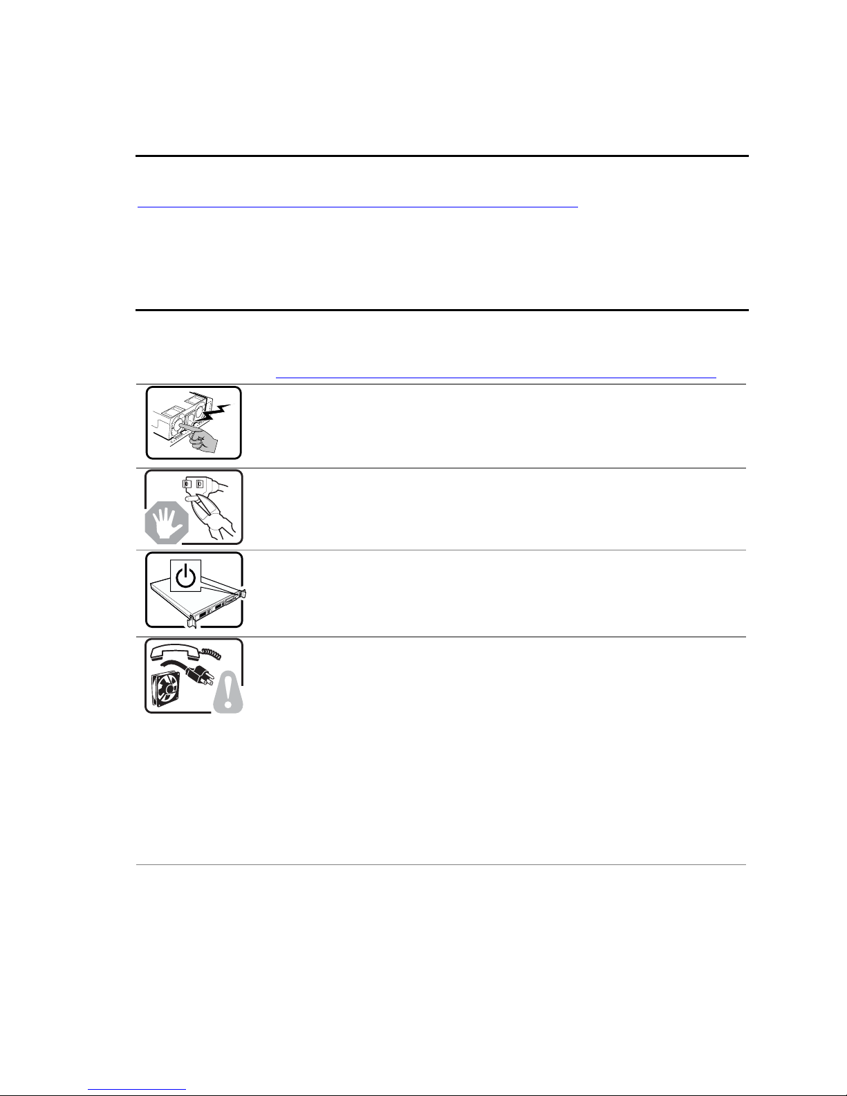
Warnings
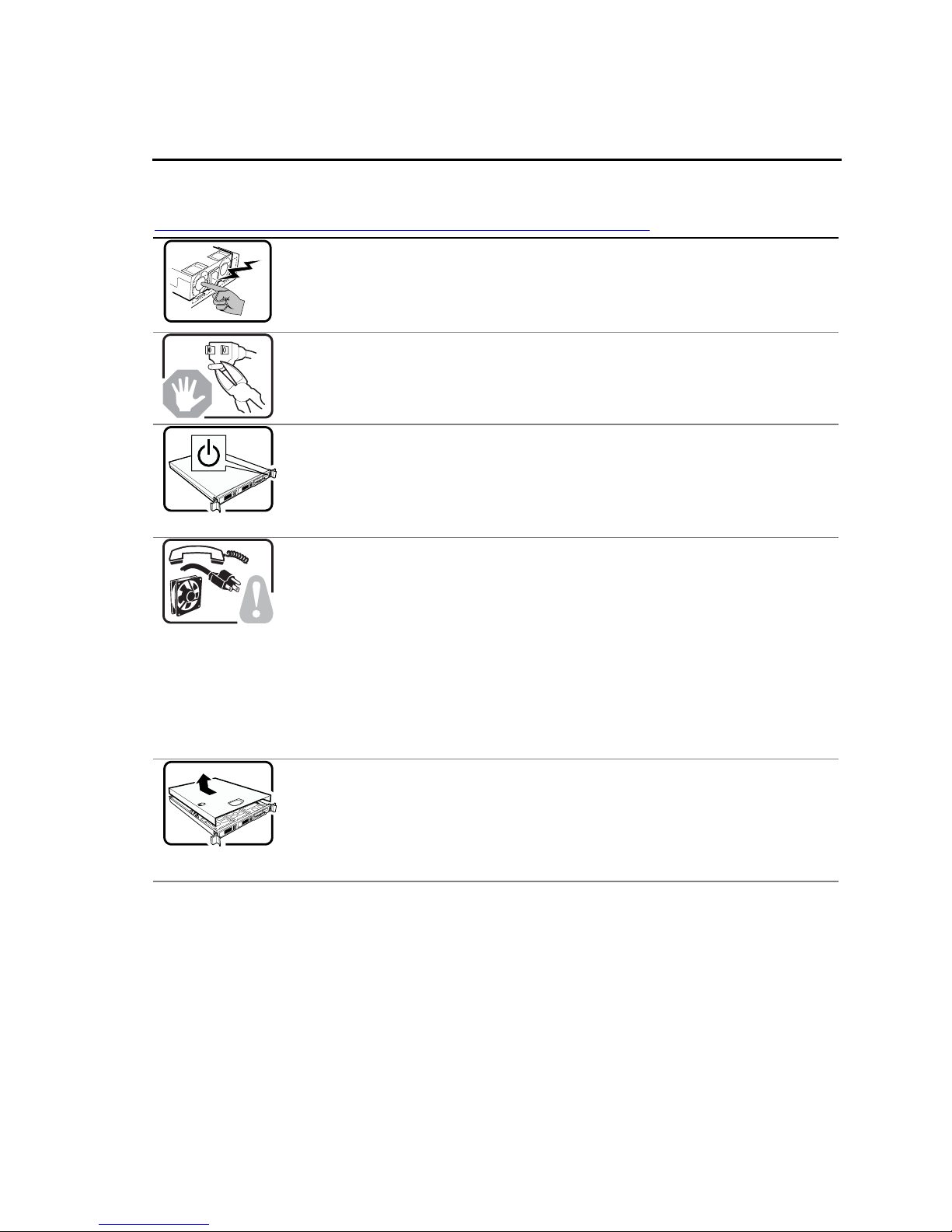
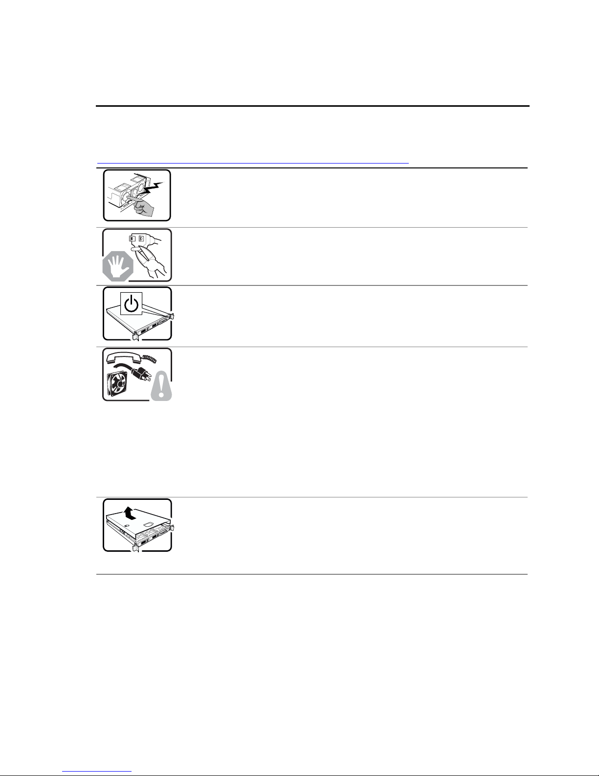
System power on/off: The power button DOES NOT turn off the system
AC or DC power. To remove power from system, you must unplug the AC
power cord from the wall outlet or remove the DC external source. Make
sure the AC power cord is unplugged or DC external source removed before
you open the chassis, add, or remove any components.
Hazardous conditions, devices and cables: Hazardous electrical
conditions may be present on power, telephone, and communication cables.
Turn off the server and disconnect the power cord, telecommunications
systems, networks, and modems attached to the server before opening it.
Otherwise, personal injury or equipment damage can result.
Electrostatic discharge (ESD) and ESD protection: ESD can
damage disk drives, boards, and other parts. We recommend that you
perform all procedures in this chapter only at an ESD workstation. If one is
not available, provide some ESD protection by wearing an antistatic wrist
strap attached to chassis ground⎯any unpainted metal surface⎯on your
server when handling parts.
ESD and handling boards: Always handle boards carefully. They can be
extremely sensitive to ESD. Hold boards only by their edges. After removing
a board from its protective wrapper or from the server, place the board
component side up on a grounded, static free surface. Use a conductive foam
pad if available but not the board wrapper. Do not slide board over any
surface.
Installing or removing jumpers: A jumper is a small plastic encased
conductor that slips over two jumper pins. Some jumpers have a small tab on
top that you can grip with your fingertips or with a pair of fine needle nosed
pliers. If your jumpers do not have such a tab, take care when using needle
nosed pliers to remove or install a jumper; grip the narrow sides of the
jumper with the pliers, never the wide sides. Gripping the wide sides can
damage the contacts inside the jumper, causing intermittent problems with
the function controlled by that jumper. Take care to grip with, but not
squeeze, the pliers or other tool you use to remove a jumper, or you may
bend or break the stake pins on the board.
viii
Page 9
Preface
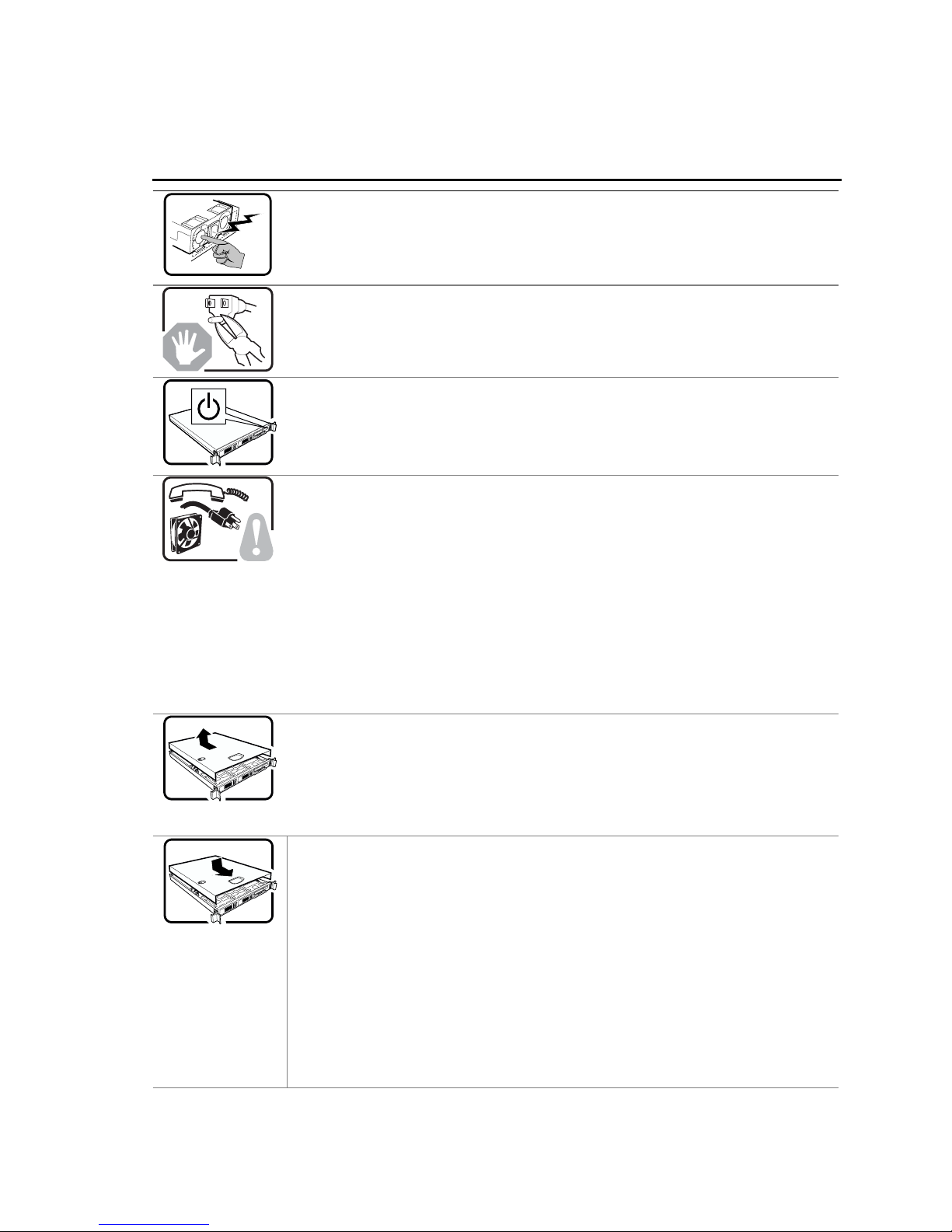
Safety Cautions
Read all caution and safety statements in this document before performing any of the instructions.
See also Intel Server Boards and Server Chassis Safety Information at
http://support.intel.com/support/motherboards/server/sb/CS-010770.htm.
The power supply in this product contains no user-serviceable parts. There may be
more than one supply in this product. Refer servicing only to qualified personnel.
Do not attempt to modify or use the supplied AC power cord if it is not the exact type
required. A product with more than one power supply will have a separate AC power
cord for each supply.
The power button on the system does not turn off system AC power. To remove AC
power from the system, you must unplug each AC power cord from the wall outlet or
power supply.
The power cord(s) is considered the disconnect device to the main (AC) power. The
socket outlet that the system plugs into shall be installed near the equipment and shall
be easily accessible.
SAFETY STEPS: Whenever you remove the chassis covers to access the inside of
the system, follow these steps:
1. Turn off all peripheral devices connected to the system.
2. Turn off the system by pressing the power button.
3. Unplug all AC power cords from the system or from wall outlets.
4. Label and disconnect all cables connected to I/O connectors or ports on the
back of the system.
5. Provide some electrostatic discharge (ESD) protection by wearing an
antistatic wrist strap attached to chassis ground of the system—any
unpainted metal surface—when handling components.
6. Do not operate the system with the chassis covers removed.
After you have completed the six SAFETY steps above, you can remove the system
covers. To do this:
1. Unlock and remove the padlock from the back of the system if a padlock has
been installed.
2. Remove and save all screws from the covers.
3. Remove the covers.
Intel® Server Chassis SR2400/SR2400DC User Guide ix
Page 10
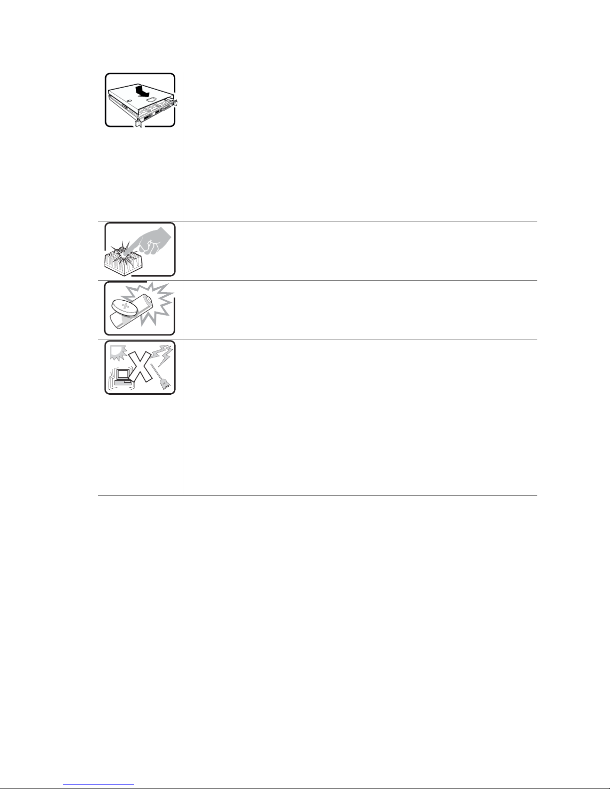
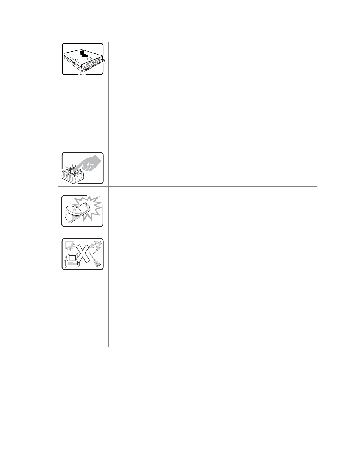
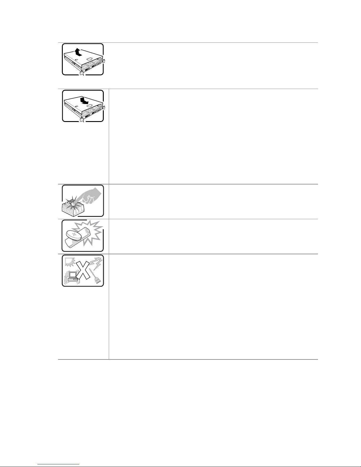
For proper cooling and airflow, always reinstall the chassis covers before turning on
the system. Operating the system without the covers in place can damage system
parts. To install the covers:
1. Check first to make sure you have not left loose tools or parts inside the
A microprocessor and heat sink may be hot if the system has been running. Also,
there may be sharp pins and edges on some board and chassis parts. Contact should
be made with care. Consider wearing protective gloves.
Danger of explosion if the battery is incorrectly replaced. Replace only with the same
or equivalent type recommended by the equipment manufacturer. Dispose of used
batteries according to manufacturer’s instructions.
system.
2. Check that cables, add-in boards, and other components are properly
installed.
3. Attach the covers to the chassis with the screws removed earlier, and tighten
them firmly.
4. Insert and lock the padlock to the system to prevent unauthorized access
inside the system.
5. Connect all external cables and the AC power cord(s) to the system.
The system is designed to operate in a typical office environment. Choose a site that
is:
Clean and free of airborne particles (other than normal room dust).
Well ventilated and away from sources of heat including direct sunlight.
Away from sources of vibration or physical shock.
Isolated from strong electromagnetic fields produced by electrical devices.
In regions that are susceptible to electrical storms, we recommend you plug
your system into a surge suppresser and disconnect telecommunication lines
to your modem during an electrical storm.
Provided with a properly grounded wall outlet.
Provided with sufficient space to access the power supply cord(s), because
they serve as the product’s main power disconnect.
x
Page 11
Preface
Wichtige Sicherheitshinweise
Lesen Sie zunächst sämtliche Warn- und Sicherheitshinweise in diesem Dokument, bevor Sie eine
der Anweisungen ausführen. Beachten Sie hierzu auch die Sicherheitshinweise zu IntelServerplatinen und Servergehäusen unter
http://support.intel.com/support/motherboards/server/sb/CS-010770.htm.
Benutzer können am Netzgerät dieses Produkts keine Reparaturen vornehmen. Das
Produkt enthält möglicherweise mehrere Netzgeräte. Wartungsarbeiten müssen von
qualifizierten Technikern ausgeführt werden.
Versuchen Sie nicht, das mitgelieferte Netzkabel zu ändern oder zu verwenden, wenn
es sich nicht genau um den erforderlichen Typ handelt. Ein Produkt mit mehreren
Netzgeräten hat für jedes Netzgerät ein eigenes Netzkabel.
Der Wechselstrom des Systems wird durch den Ein-/Aus-Schalter für Gleichstrom
nicht ausgeschaltet. Ziehen Sie jedes Wechselstrom-Netzkabel aus der Steckdose
bzw. dem Netzgerät, um den Stromanschluß des Systems zu unterbrechen.
SICHERHEISMASSNAHMEN: Immer wenn Sie die Gehäuseabdeckung abnehmen
um an das Systeminnere zu gelangen, sollten Sie folgende Schritte beachten:
1. Schalten Sie alle an Ihr System angeschlossenen Peripheriegeräte aus.
2. Schalten Sie das System mit dem Hauptschalter aus.
3. Ziehen Sie den Stromanschlußstecker Ihres Systems aus der Steckdose.
4. Auf der Rückseite des Systems beschriften und ziehen Sie alle
Anschlußkabel von den I/O Anschlüssen oder Ports ab.
5. Tragen Sie ein geerdetes Antistatik Gelenkband, um elektrostatische
Ladungen (ESD) über blanke Metallstellen bei der Handhabung der
Komponenten zu vermeiden.
6. Schalten Sie das System niemals ohne ordnungsgemäß montiertes Gehäuse
ein.
Nachdem Sie die oben erwähnten ersten sechs SICHERHEITSSCHRITTE
durchgeführt haben, können Sie die Abdeckung abnehmen, indem Sie:
1. Öffnen und entfernen Sie die Verschlußeinrichtung (Padlock) auf der
Rückseite des Systems, falls eine Verschlußeinrichtung installiert ist.
2. Entfernen Sie alle Schrauben der Gehäuseabdeckung.
3. Nehmen Sie die Abdeckung ab.
Intel® Server Chassis SR2400/SR2400DC User Guide xi
Page 12
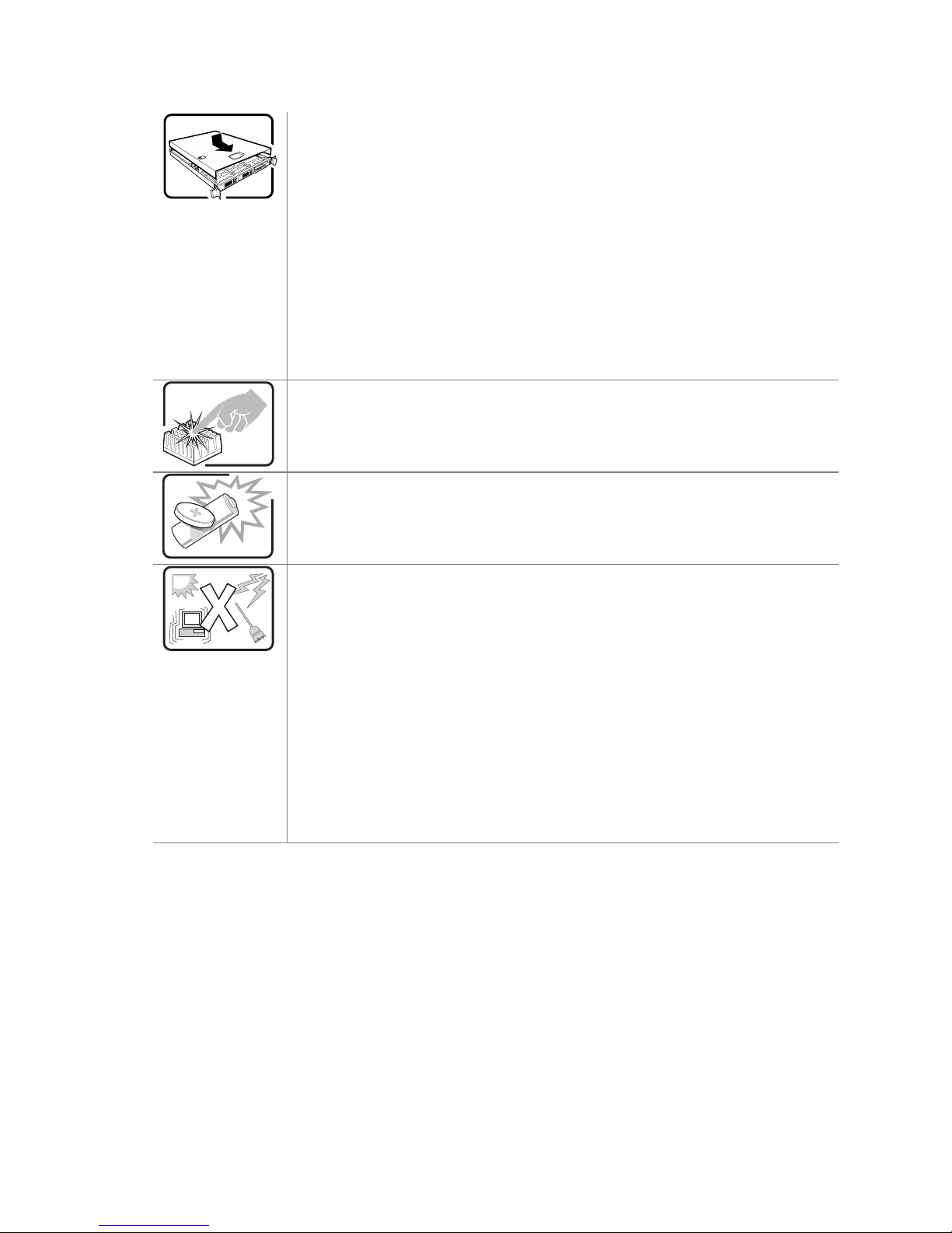
Zur ordnungsgemäßen Kühlung und Lüftung muß die Gehäuseabdeckung immer
wieder vor dem Einschalten installiert werden. Ein Betrieb des Systems ohne
angebrachte Abdeckung kann Ihrem System oder Teile darin beschädigen. Um die
Abdeckung wieder anzubringen:
1. Vergewissern Sie sich, daß Sie keine Werkzeuge oder Teile im Innern des
Der Mikroprozessor und der Kühler sind möglicherweise erhitzt, wenn das System in
Betrieb ist. Außerdem können einige Platinen und Gehäuseteile scharfe Spitzen und
Kanten aufweisen. Arbeiten an Platinen und Gehäuse sollten vorsichtig ausgeführt
werden. Sie sollten Schutzhandschuhe tragen.
Bei falschem Einsetzen einer neuen Batterie besteht Explosionsgefahr. Die Batterie
darf nur durch denselben oder einen entsprechenden, vom Hersteller empfohlenen
Batterietyp ersetzt werden. Entsorgen Sie verbrauchte Batterien den Anweisungen
des Herstellers entsprechend.
Systems zurückgelassen haben.
2. Überprüfen Sie alle Kabel, Zusatzkarten und andere Komponenten auf
ordnungsgemäßen Sitz und Installation.
3. Bringen Sie die Abdeckungen wieder am Gehäuse an, indem Sie die zuvor
gelösten Schrauben wieder anbringen. Ziehen Sie diese gut an.
4. Bringen Sie die Verschlußeinrichtung (Padlock) wieder an und schließen Sie
diese, um ein unerlaubtes Öffnen des Systems zu verhindern.
5. Schließen Sie alle externen Kabel und den AC Stromanschlußstecker Ihres
Systems wieder an.
Das System wurde für den Betrieb in einer normalen Büroumgebung entwickelt. Der
Standort sollte:
sauber und staubfrei sein (Hausstaub ausgenommen);
gut gelüftet und keinen Heizquellen ausgesetzt sein (einschließlich direkter
Sonneneinstrahlung);
keinen Erschütterungen ausgesetzt sein;
keine starken, von elektrischen Geräten erzeugten elektromagnetischen
Felder aufweisen;
in Regionen, in denen elektrische Stürme auftreten, mit einem
Überspannungsschutzgerät verbunden sein; während eines elektrischen
Sturms sollte keine Verbindung der Telekommunikationsleitungen mit dem
Modem bestehen;
mit einer geerdeten Wechselstromsteckdose ausgerüstet sein;
über ausreichend Platz verfügen, um Zugang zu den Netzkabeln zu
gewährleisten, da der Stromanschluß des Produkts hauptsächlich über die
Kabel unterbrochen wird.
xii
Page 13
Preface
重要安全指导
在执行任何指令之前,请阅读本文档中的所有注意事项及安全声明。和/或
http://support.intel.com/support/motherboards/server/sb/CS-010770.htm 上的
Boards and Server Chassis Safety Information
(《Intel
Intel Server
服务器主板与服务器机箱安全信息》)。
Consignes de sécurité
Lisez attention toutes les consignes de sécurité et les mises en garde indiquées dans ce document
avant de suivre toute instruction. Consultez Intel Server Boards and Server Chassis Safety
Information sur le site
http://support.intel.com/support/motherboards/server/sb/CS-010770.htm.
Le bloc d'alimentation de ce produit ne contient aucune pièce pouvant être réparée
par l'utilisateur. Ce produit peut contenir plus d'un bloc d'alimentation. Veuillez
contacter un technicien qualifié en cas de problème.
Ne pas essayer d'utiliser ni modifier le câble d'alimentation CA fourni, s'il ne
correspond pas exactement au type requis. Le nombre de câbles d'alimentation CA
fournis correspond au nombre de blocs d'alimentation du produit.
Notez que le commutateur CC de mise sous tension /hors tension du panneau avant
n'éteint pas l'alimentation CA du système. Pour mettre le système hors tension, vous
devez débrancher chaque câble d'alimentation de sa prise.
CONSIGNES DE SÉCURITÉ -Lorsque vous ouvrez le boîtier pour accéder à
l’intérieur du système, suivez les consignes suivantes:
1. Mettez hors tension tous les périphériques connectés au système.
2. Mettez le système hors tension en mettant l’interrupteur général en position
OFF (bouton-poussoir).
3. Débranchez tous les cordons d’alimentation c.a. du système et des prises
murales.
4. Identifiez et débranchez tous les câbles reliés aux connecteurs d’E-S ou aux
accès derrière le système.
5. Pour prévenir les décharges électrostatiques lorsque vous touchez aux
composants, portez une bande antistatique pour poignet et reliez-la à la
masse du système (toute surface métallique non peinte du boîtier).
6. Ne faites pas fonctionner le système tandis que le boîtier est ouvert.
Intel® Server Chassis SR2400/SR2400DC User Guide xiii
Page 14
Une fois TOUTES les étapes précédentes accomplies, vous pouvez retirer les
panneaux du système. Procédez comme suit:
1. Si un cadenas a été installé sur à l’arrière du système, déverrouillez-le et
retirez-le.
2. Retirez toutes les vis des panneaux et mettez-les dans un endroit sûr.
3. Retirez les panneaux.
Afin de permettre le refroidissement et l’aération du système, réinstallez toujours les
panneaux du boîtier avant de mettre le système sous tension. Le fonctionnement du
système en l’absence des panneaux risque d’endommager ses pièces. Pour installer
les panneaux, procédez comme suit:
1. Assurez-vous de ne pas avoir oublié d’outils ou de pièces démontées dans le
Le microprocesseur et le dissipateur de chaleur peuvent être chauds si le système a
été sous tension. Faites également attention aux broches aiguës des cartes et aux
bords tranchants du capot. Nous vous recommandons l'usage de gants de protection.
système.
2. Assurez-vous que les câbles, les cartes d’extension et les autres
composants sont bien installés.
3. Revissez solidement les panneaux du boîtier avec les vis retirées plus tôt.
4. Remettez le cadenas en place et verrouillez-le afin de prévenir tout accès
non autorisé à l’intérieur du système.
5. Rebranchez tous les cordons d’alimentation c. a. et câbles externes au
système.
Danger d'explosion si la batterie n'est pas remontée correctement. Remplacer
uniquement avec une batterie du même type ou d'un type équivalent recommandé par
le fabricant. Disposez des piles usées selon les instructions du fabricant.
Le système a été conçu pour fonctionner dans un cadre de travail normal.
L'emplacement choisi doit être:
Propre et dépourvu de poussière en suspension (sauf la poussière normale).
Bien aéré et loin des sources de chaleur, y compris du soleil direct.
A l'abri des chocs et des sources de vibrations.
Isolé de forts champs électromagnétiques géenérés par des appareils
électriques.
Dans les régions sujettes aux orages magnétiques il est recomandé de
brancher votre système à un supresseur de surtension, et de débrancher
toutes les lignes de télécommunications de votre modem durant un orage.
Muni d'une prise murale correctement mise à la terre.
Suffisamment spacieux pour vous permettre d'accéder aux câbles
d'alimentation (ceux-ci étant le seul moyen de mettre le système hors
tension).
xiv
Page 15

Preface
Instrucciones de seguridad importantes
Lea todas las declaraciones de seguridad y precaución de este documento antes de realizar
cualquiera de las instrucciones. Vea Intel Server Boards and Server Chassis Safety Information en
http://support.intel.com/support/motherboards/server/sb/CS-010770.htm.
en
El usuario debe abstenerse de manipular los componentes de la fuente de
alimentación de este producto, cuya reparación debe dejarse exclusivamente en
manos de personal técnico especializado. Puede que este producto disponga de más
de una fuente de alimentación.
No intente modificar ni usar el cable de alimentación de corriente alterna, si no
corresponde exactamente con el tipo requerido.
El número de cables suministrados se corresponden con el número de fuentes de
alimentación de corriente alterna que tenga el producto.
Nótese que el interruptor activado/desactivado en el panel frontal no desconecta la
corriente alterna del sistema. Para desconectarla, deberá desenchufar todos los
cables de corriente alterna de la pared o desconectar la fuente de alimentación.
INSTRUCCIONES DE SEGURIDAD: Cuando extraiga la tapa del chasis para
acceder al interior del sistema, siga las siguientes instrucciones:
1. Apague todos los dispositivos periféricos conectados al sistema.
2. Apague el sistema presionando el interruptor encendido/apagado.
3. Desconecte todos los cables de alimentación CA del sistema o de las tomas
de corriente alterna.
4. Identifique y desconecte todos los cables enchufados a los conectores E/S o
a los puertos situados en la parte posterior del sistema.
5. Cuando manipule los componentes, es importante protegerse contra la
descarga electrostática (ESD). Puede hacerlo si utiliza una muñequera
antiestática sujetada a la toma de tierra del chasis — o a cualquier tipo de
superficie de metal sin pintar.
6. No ponga en marcha el sistema si se han extraído las tapas del chasis.
Después de completar las seis instrucciones de SEGURIDAD mencionadas, ya puede
extraer las tapas del sistema. Para ello:
1. Desbloquee y extraiga el bloqueo de seguridad de la parte posterior del
sistema, si se ha instalado uno.
2. Extraiga y guarde todos los tornillos de las tapas.
3. Extraiga las tapas.
Intel® Server Chassis SR2400/SR2400DC User Guide xv
Page 16
Para obtener un enfriamiento y un flujo de aire adecuados, reinstale siempre las tapas
del chasis antes de poner en marcha el sistema. Si pone en funcionamiento el
sistema sin las tapas bien colocadas puede dañar los componentes del sistema. Para
instalar las tapas:
1. Asegúrese primero de no haber dejado herramientas o componentes sueltos
Si el sistema ha estado en funcionamiento, el microprocesador y el disipador de calor
pueden estar aún calientes. También conviene tener en cuenta que en el chasis o en
el tablero puede haber piezas cortantes o punzantes. Por ello, se recomienda
precaución y el uso de guantes protectores.
Existe peligro de explosión si la pila no se cambia de forma adecuada. Utilice
solamente pilas iguales o del mismo tipo que las recomendadas por el fabricante del
equipo. Para deshacerse de las pilas usadas, siga igualmente las instrucciones del
fabricante.
El sistema está diseñado para funcionar en un entorno de trabajo normal. Escoja un
lugar:
dentro del sistema.
2. Compruebe que los cables, las placas adicionales y otros componentes se
hayan instalado correctamente.
3. Incorpore las tapas al chasis mediante los tornillos extraídos anteriormente,
tensándolos firmemente.
4. Inserte el bloqueo de seguridad en el sistema y bloquéelo para impedir que
pueda accederse al mismo sin autorización.
5. Conecte todos los cables externos y los cables de alimentación CA al
sistema.
Limpio y libre de partículas en suspensión (salvo el polvo normal).
Bien ventilado y alejado de fuentes de calor, incluida la luz solar directa.
Alejado de fuentes de vibración.
Aislado de campos electromagnéticos fuertes producidos por dispositivos
eléctricos.
En regiones con frecuentes tormentas eléctricas, se recomienda conectar su
sistema a un eliminador de sobrevoltage y desconectar el módem de las
líneas de telecomunicación durante las tormentas.
Provisto de una toma de tierra correctamente instalada.
Provisto de espacio suficiente como para acceder a los cables de
alimentación, ya que éstos hacen de medio principal de desconexión del
sistema.
xvi
Page 17
Preface
AVVERTENZA: Italiano
Rivolgersi ad un tecnico specializzato per la riparazione dei componenti
dell'alimentazione di questo prodotto. È possibile che il prodotto disponga di più fonti
di alimentazione.
Non modificare o utilizzare il cavo di alimentazione in c.a. fornito dal produttore, se
non corrisponde esattamente al tipo richiesto. Ad ogni fonte di alimentazione
corrisponde un cavo di alimentazione in c.a. separato.
L’interruttore attivato/disattivato nel pannello anteriore non interrompe l’alimentazione
in c.a. del sistema. Per interromperla, è necessario scollegare tutti i cavi di
alimentazione in c.a. dalle prese a muro o dall’alimentazione di corrente.
PASSI DI SICUREZZA: Qualora si rimuovano le coperture del telaio per accedere
all’interno del sistema, seguire i seguenti passi:
1. Spegnere tutti i dispositivi periferici collegati al sistema.
2. Spegnere il sistema, usando il pulsante spento/acceso dell’interruttore del
sistema.
3. Togliere tutte le spine dei cavi del sistema dalle prese elettriche.
4. Identificare e sconnettere tutti i cavi attaccati ai collegamenti I/O od alle prese
installate sul retro del sistema.
5. Qualora si tocchino i componenti, proteggersi dallo scarico elettrostatico
(SES), portando un cinghia anti-statica da polso che è attaccata alla presa a
terra del telaio del sistema – qualsiasi superficie non dipinta – .
6. Non far operare il sistema quando il telaio è senza le coperture.
Dopo aver seguito i sei passi di SICUREZZA sopracitati, togliere le coperture del
telaio del sistema come seque:
1. Aprire e rimuovere il lucchetto dal retro del sistema qualora ve ne fosse uno
installato.
2. Togliere e mettere in un posto sicuro tutte le viti delle coperture.
3. Togliere le coperture.
Per il giusto flusso dell’aria e raffreddamento del sistema, rimettere sempre le
coperture del telaio prima di riaccendere il sistema. Operare il sistema senza le
coperture al loro proprio posto potrebbe danneggiare i componenti del sistema. Per
rimettere le coperture del telaio:
1. Controllare prima che non si siano lasciati degli attrezzi o dei componenti
dentro il sistema.
2. Controllare che i cavi, dei supporti aggiuntivi ed altri componenti siano stati
installati appropriatamente.
3. Attaccare le coperture al telaio con le viti tolte in precedenza e avvitarle
strettamente.
4. Inserire e chiudere a chiave il lucchetto sul retro del sistema per impedire
l’accesso non autorizzato al sistema.
5. Ricollegare tutti i cavi esterni e le prolunghe AC del sistema.
Intel® Server Chassis SR2400/SR2400DC User Guide xvii
Page 18
Se il sistema è stato a lungo in funzione, il microprocessore e il dissipatore di calore
potrebbero essere surriscaldati. Fare attenzione alla presenza di piedini appuntiti e
parti taglienti sulle schede e sul telaio. È consigliabile l'uso di guanti di protezione.
Esiste il pericolo di un esplosione se la pila non viene sostituita in modo corretto.
Utilizzare solo pile uguali o di tipo equivalente a quelle consigliate dal produttore. Per
disfarsi delle pile usate, seguire le istruzioni del produttore.
Il sistema è progettato per funzionare in un ambiente di lavoro tipo. Scegliere una
postazione che sia:
Pulita e libera da particelle in sospensione (a parte la normale polvere
presente nell'ambiente).
Ben ventilata e lontana da fonti di calore, compresa la luce solare diretta.
Al riparo da urti e lontana da fonti di vibrazione.
Isolata dai forti campi magnetici prodotti da dispositivi elettrici.
In aree soggette a temporali, è consigliabile collegare il sistema ad un
limitatore di corrente. In caso di temporali, scollegare le linee di
comunicazione dal modem.
Dotata di una presa a muro correttamente installata.
Dotata di spazio sufficiente ad accedere ai cavi di alimentazione, i quali
rappresentano il mezzo principale di scollegamento del sistema.
xviii
Page 19

Contents
Contents
1 Server Chassis Features ............................................................................... 1
Component Identification ........................................................................................................ 4
Internal Components...................................................................................................... 4
Hot-Swap SATA Backplane Connections ......................................................................5
Hot-Swap SCSI Backplane Connections .......................................................................5
Standard Control Panel.................................................................................................. 6
®
Intel
Local Control Panel...............................................................................................7
Back Panel Features...................................................................................................... 8
Peripheral Devices.................................................................................................................. 9
Hard Disk Drives ............................................................................................................9
Floppy / CD-ROM / DVD-ROM Drives .........................................................................10
Tape Drive.................................................................................................................... 10
Advanced Management Options...........................................................................................11
Rack-Mounted Systems........................................................................................................ 11
Front Bezels.......................................................................................................................... 11
®
Intel
Management Module ..........................................................................................11
2 Hardware Installations and Upgrades........................................................ 13
Before You Begin.................................................................................................................. 13
Tools and Supplies Needed .........................................................................................13
System References...................................................................................................... 13
Removing and Installing the Chassis Cover .........................................................................14
Removing the Chassis Cover....................................................................................... 14
Installing the Chassis Cover......................................................................................... 15
Removing and Installing the Front Bezel ..............................................................................16
Removing the Front Bezel............................................................................................ 16
Installing the Front Bezel.............................................................................................. 17
Removing and Installing the Processor Air Duct and Processor Air Dam............................. 18
Removing the Processor Air Duct ................................................................................18
Installing the Processor Air Duct ..................................................................................19
Removing the Processor Air Dam................................................................................20
Installing the Processor Air Dam.................................................................................. 21
Removing and Installing the Air Baffles ................................................................................21
Removing the Large Hot-swap Air Baffle (Backplane Installed)...................................22
Installing the Large Hot-swap Air Baffle (Backplane Installed).....................................23
Removing the Small Hot-swap Air Baffle (Backplane Installed)...................................24
Installing the Small Hot-swap Air Baffle (Backplane Installed).....................................25
Removing the Fixed Drive Air Baffle (No Backplane Installed) ....................................26
Installing the Fixed Drive Air Baffle (No Backplane Installed) ......................................27
Removing and Installing the Fan Module..............................................................................28
Removing the Fan Module ...........................................................................................28
Installing the Fan Module .............................................................................................29
Installing and Removing a Hard Disk Drive........................................................................... 31
Removing a SATA or SCSI Hot-swap Hard Disk Drive................................................31
Intel® Server Chassis SR2400/SR2400DC User Guide xix
Page 20

Installing a SATA or SCSI Hot-swap Hard Disk Drive..................................................32
Installing a Fixed SATA Hard Disk Drive...................................................................... 36
Removing a Fixed SATA Hard Disk Drive....................................................................41
Installing the SATA or SCSI Sixth Drive Accessory..............................................................42
Installing or Removing a Floppy Drive (Slimline or Standard)............................................... 44
Installing a Floppy Drive into Slimline Bay (Backplane Installed)................................. 44
Removing a Floppy Drive from the Slimline Bay (Backplane Installed) .......................47
Installing Floppy Drive into Slimline Bay (No Backplane Installed) ..............................48
Removing a Floppy Drive from the Slimline Bay (No Backplane Installed)..................52
Installing a Floppy Drive into the Converted Hard Drive Bay (Backplane Installed)..... 53
Removing a Floppy Drive from the Converted Hard Drive Bay....................................57
Installing or Removing a CD-ROM or DVD-ROM Drive ........................................................57
Installing a DVD-ROM or CD-ROM Drive into Slimline Bay (Backplane Installed) ......58
Removing a CD-ROM or DVD-ROM Drive from the Slimline Bay (Backplane Installed)59
Installing a DVD-ROM or CD-ROM Drive into Slimline Bay (No Backplane Installed). 60
Removing a DVD-ROM or CD-ROM Drive from Slimline Bay (No Backplane Installed)62
Removing and Installing the PCI Riser Assembly.................................................................63
Removing the PCI Riser Assembly ..............................................................................63
Installing the PCI Riser Assembly ................................................................................64
Installing and Removing a PCI Riser Connector...................................................................65
Removing a PCI Riser Connector ................................................................................66
Installing a PCI Riser Connector ..................................................................................67
Installing and Removing a PCI Add-in Card.......................................................................... 68
Installing a PCI Add-in Card......................................................................................... 68
Removing a PCI Add-in Card....................................................................................... 69
Replacing the Control Panel .................................................................................................69
Replacing a System Fan....................................................................................................... 71
Replacing the Power Supply Distribution Module (AC Version)............................................ 72
Replacing the Power Supply Distribution Module (DC Version) ...........................................77
Installing or Replacing a Hot-swap Power Supply (AC Version)...........................................83
Removing a Hot-swap Power Supply...........................................................................83
Installing a Hot-swap Power Supply.............................................................................84
Installing or Replacing a Hot-swap Power Supply (DC Version)........................................... 84
Removing a Hot-swap Power Supply...........................................................................84
Installing a Hot-swap Power Supply.............................................................................85
Installing or Removing the SATA or SCSI Backplane...........................................................85
Removing a SATA or SCSI Backplane ........................................................................86
Installing a Replacement SATA or SCSI Backplane ....................................................87
Installing a Tape Drive ..........................................................................................................90
Filling Empty Chassis Bays...................................................................................................93
Technical Reference ......................................................................................... 95
Power Supply Specifications.................................................................................................95
700-W Redundant Power Supply Input Voltages (AC Version only)............................95
700-W Single Power Supply Output Voltages..............................................................95
600-W Redundant Power Supply Input Voltage (DC Version only) .............................95
600-W Single Power Supply Output Voltages..............................................................96
System Environmental Specifications................................................................................... 96
xx
Page 21

Contents
Equipment Log and Worksheets ..................................................................... 97
Equipment Log...................................................................................................................... 97
Current Usage.......................................................................................................................99
Calculating Power Usage............................................................................................. 99
Product Regulatory Compliance .........................................................................................101
Product Safety Compliance........................................................................................ 101
Product EMC Compliance – Class A Compliance......................................................101
Certifications / Registrations / Declarations................................................................102
Product Regulatory Compliance Markings................................................................. 102
Electromagnetic Compatibility Notices................................................................................103
FCC (USA) .................................................................................................................103
Industry Canada (ICES-003)...................................................................................... 104
Europe (CE Declaration of Conformity)......................................................................104
VCCI (Japan)..............................................................................................................105
BSMI (Taiwan)............................................................................................................105
Korean RRL Compliance............................................................................................105
Regulated Specified Components.............................................................................. 106
Intel® Server Issue Report Form..................................................................... 109
Warranty........................................................................................................... 113
Limited Warranty for Intel
Extent of Limited Warranty..................................................................................................113
Warranty Limitations and Exclusions ..................................................................................114
Limitations of Liability .................................................................................................114
How to Obtain Warranty Service.........................................................................................115
Telephone Support..................................................................................................... 115
Returning a Defective Product ...................................................................................115
®
Chassis Subassembly Products.............................................113
Figures
Figure 1. Intel
Figure 2. Internal Component Locations...................................................................................... 4
Figure 3. Rear of SATA Backplane..............................................................................................5
Figure 4. Rear of SCSI Backplane............................................................................................... 5
Figure 5. Standard Control Panel ................................................................................................6
Figure 6. Intel
Figure 7. Chassis Back................................................................................................................8
Figure 8. Optional Peripherals .....................................................................................................9
Figure 9. Removing the Chassis Cover ..................................................................................... 14
Figure 10. Installing the Chassis Cover .....................................................................................15
Figure 11. Removing the Front Bezel ........................................................................................ 16
Figure 12. Installing the Front Bezel ..........................................................................................17
Figure 13. Removing the Processor Air Duct............................................................................. 18
Figure 14. Installing the Processor Air Duct............................................................................... 19
Figure 15. Installing the Processor Air Dam ..............................................................................20
Figure 16. Removing the Large Hot-swap Air Baffle.................................................................. 22
Figure 17. Installing the Large Hot-swap Air Baffle.................................................................... 23
Figure 18. Removing the Small Hot-swap Air Baffle.................................................................. 24
®
Server Chassis SR2400/SR2400DC ...................................................................1
®
Local Control Panel ............................................................................................. 8
Intel® Server Chassis SR2400/SR2400DC User Guide xxi
Page 22

Figure 19. Installing the Small Hot-swap Air Baffle.................................................................... 25
Figure 20. Removing the Fixed Drive Air Baffle......................................................................... 26
Figure 21. Installing the Fixed Drive Air Baffle........................................................................... 27
Figure 22. Removing the Fan Module........................................................................................ 28
Figure 23. Connecting the Fan Distribution Cable.....................................................................29
Figure 24. Installing the Fan Module.......................................................................................... 30
Figure 25. Removing the Hot-swap Hard Drive Carrier from the Chassis .................................31
Figure 26. Removing the Retention Device from the Hot-swap Drive Carrier............................32
Figure 27. Attaching a Hot-swap Hard Disk Drive to a Drive Carrier .........................................32
Figure 28. Inserting a Hot-swap Hard Disk Drive Assembly into the Chassis............................33
Figure 29. Connecting the Hot-swap SATA Data Cables .......................................................... 34
Figure 30. Connecting the SCSI Data Cable ............................................................................. 35
Figure 31. Removing a Fixed Hard Drive Carrier from the Chassis........................................... 36
Figure 32. Removing the Retention Device from the Fixed Drive Carrier.................................. 37
Figure 33. Attaching a Hard Drive to the Fixed Drive Carrier ....................................................37
Figure 34. Installing the Fixed SATA Drive Power Cables......................................................... 38
Figure 35. Installing the Fixed SATA Drive Data Cables ........................................................... 39
Figure 36. Installing the Fixed SATA Drive Power Cables......................................................... 40
Figure 37. Remove the Drive Blank from the Chassis ...............................................................42
Figure 38. Installing the Sixth Drive Board................................................................................. 43
Figure 39. Installing a Floppy Drive into the Slimline Carrier.....................................................45
Figure 40. Connecting the Flat Flex Cable to a Floppy Drive .................................................... 46
Figure 41. Installing the Slimline Floppy Drive into the Chassis ................................................46
Figure 42. Installing a Slimline Floppy Drive into the Carrier.....................................................48
Figure 43. Connecting the Flat Flex Cable to a Floppy Drive .................................................... 49
Figure 44. Installing the Floppy Drive Interposer Board............................................................. 50
Figure 45. Connecting the Floppy Drive Cables ........................................................................ 51
Figure 46. Removing the Rails from the Floppy Drive Conversion Kit Carrier........................... 53
Figure 47. Inserting a Floppy Drive into the Floppy Drive Conversion Kit Carrier......................54
Figure 48. Attaching a Floppy Drive to the Floppy Drive Conversion Kit Carrier .......................54
Figure 49. Installing the Rails onto the Floppy Drive Conversion Kit Carrier.............................55
Figure 50. Connecting the Flat Flex Cable to a Floppy Drive .................................................... 55
Figure 51. Installing the Floppy Drive into the Chassis..............................................................56
Figure 52. Installing a DVD-ROM / CD-ROM Drive into the Slimline Carrier............................. 58
Figure 53. Installing a DVD/CDROM Drive into the Chassis .....................................................59
Figure 54. Installing a DVD-ROM or CD-ROM Drive into the Slimline Carrier........................... 61
Figure 55. Installing a DVD-ROM or CD-ROM Drive into the Chassis.......................................62
Figure 56. Removing the PCI Riser Assembly from the Chassis............................................... 64
Figure 57. Installing the PCI Riser Assembly into the Chassis..................................................65
Figure 58. Removing a PCI Riser Connector from the PCI Riser Assembly..............................66
Figure 59. Installing a PCI Riser Connector............................................................................... 67
Figure 60. Installing a PCI Add-in Card .....................................................................................68
Figure 61. Removing the Control Panel from the Chassis......................................................... 70
Figure 62. Installing a System Fan ............................................................................................71
Figure 63. Disconnecting the Flex Cable from the Server Board............................................... 73
Figure 64. Disconnecting the Power Cables from the Server Board..........................................74
Figure 65. Disconnecting the Power Cable from the Backplane................................................ 74
Figure 66. Disconnecting the Flex and Power Cables...............................................................75
Figure 67. Removing the Power Distribution Module................................................................. 75
xxii
Page 23

Contents
Figure 68. Installing the Power Distribution Module................................................................... 76
Figure 69. Disconnecting the Flex Cable from the Server Board............................................... 78
Figure 70. Disconnecting the Power Cables from the Server Board..........................................79
Figure 71. Disconnecting the Power Cable from the Backplane................................................ 79
Figure 72. Disconnecting the Flex and Power Cables...............................................................80
Figure 73. Removing the Power Distribution Module................................................................. 81
Figure 74. Installing the Power Distribution Module................................................................... 82
Figure 75. Removing a Hot-swap Power Supply ....................................................................... 83
Figure 76. Removing a Hot-swap Power Supply ....................................................................... 85
Figure 77. Removing a SATA or SCSI Backplane..................................................................... 87
Figure 78. Installing a SATA or SCSI Backplane....................................................................... 88
Figure 79. Installing a SATA or SCSI Backplane....................................................................... 89
Figure 80. Removing the Tape Drive Bay Filler Panel............................................................... 90
Figure 81. Inserting a Tape Drive into the Carrier...................................................................... 91
Figure 82. Inserting the Tape Drive Carrier into the Chassis..................................................... 91
Figure 83. Connecting the Tape Drive Cables........................................................................... 92
Figure 84. Installing the Filler Panels......................................................................................... 93
Tables
Table 1. Server Chassis Features.................................................................................2
Table 2. Product Certification Markings..................................................................... 102
Table 3. Product Certification Markings..................................................................... 103
Intel® Server Chassis SR2400/SR2400DC User Guide xxiii
Page 24

xxiv
Page 25
Server Chassis Features
1 Server Chassis Features
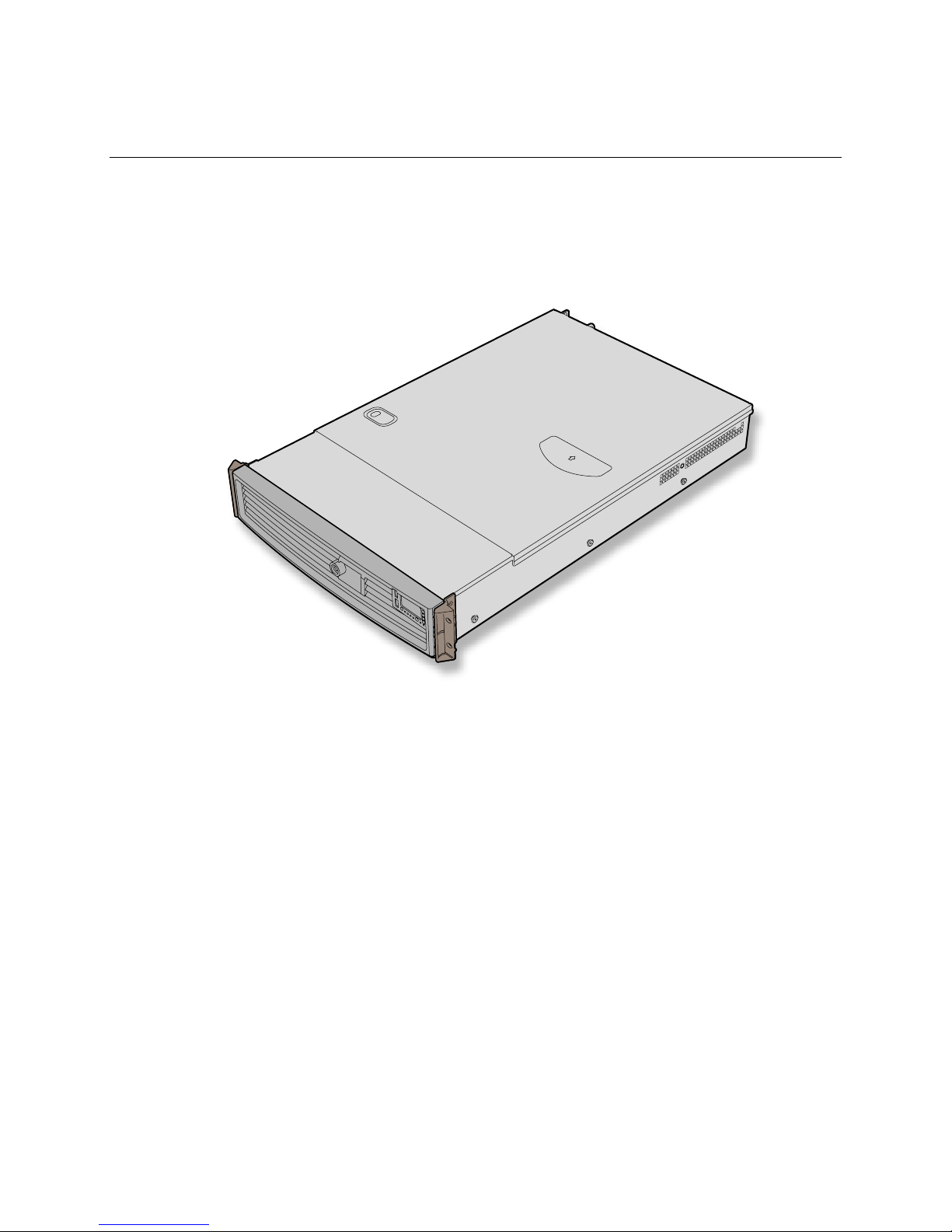
This chapter briefly describes the main features of Intel® Server Chassis SR2400/SR2400DC. This
chapter provides pictures of the product, a list of the server features, and diagrams showing the
location of important components and connections on the server chassis.
The Intel® Server Chassis SR2400/SR2400DC is shown in the following picture.
Figure 1. Intel® Server Chassis SR2400/SR2400DC
Intel® Server Chassis SR2400/SR2400DC User Guide 1
Page 26
Table 1 summarizes the major features of the server chassis.6
Table 1. Server Chassis Features
Feature Description
Dimensions
Hard Drives (dependent
on option selected)
Peripherals (dependent
on option selected)
Fans (dependent on
option selected)
Control Panel (dependent
on option selected)
LEDs and displays
(dependent on option
selected)
3.445 inches high
16.930 inches wide
26.457 inches deep
60 pounds (Base chassis weight)
Up to five fixed or hot-swap SATA or SCSI drives
Drive bay for sixth SATA or SCSI hot-swap hard drive or a 3.5 inch tape drive
Slimline bay for CD-ROM drive, DVD-ROM drive, or floppy drive
Kit to convert one hard drive bay into a floppy drive bay (optional accessory)
PCI riser card bracket
Support for up to eight system fans (four standard, four as optional
accessory)
Two non-redundant fans in power supply
Standard Control Panel
Intel® Local Control Panel (requires installation of the optional Intel®
Management Module – Advanced or Intel® Management Module –
Professional)
With Standard Control Panel:
NIC1 Activity
NIC2 Activity
Power / Sleep
System Status
System Identification
Hard Drive Activity
With Intel® Local Control Panel:
NIC1 Activity
NIC2 Activity
Power / Sleep
System Status
System Identification
Hard Drive Activity
LCD Display Screen
Continued
6
Before purchasing any component noted as either “optional,”or “dependent on option selected,” refer to
your server board documentation to determine which option(s) are supported with your server board.
2
Page 27

Server Chassis Features
Table 1. Server Chassis Features (continued)
Power Supply (AC)
Power Supply (DC)
System Security
USB
Video
One hot-swap 700-W power supply module
1+1 hot-swap redundant 700-W power supply (optional accessory)
One hot-swap 600-W power supply module
1+1 hot-swap redundant 600-W power supply (optional accessory)
Lockable front bezel (optional accessory)
Chassis intrusion switch
Lock attach point for chassis cover
One front panel USB port with Standard Control Panel
Two front panel USB ports with Intel® Local Control Panel
Two back panel USB ports
One front panel video port (available only with the Standard Control Panel)
One rear panel video port
7
7
Video connections must be used separately. The server board and chassis do not support synchronous use
of video out of the front and back of the chassis.
Intel® Server Chassis SR2400/SR2400DC User Guide 3
Page 28
Component Identification
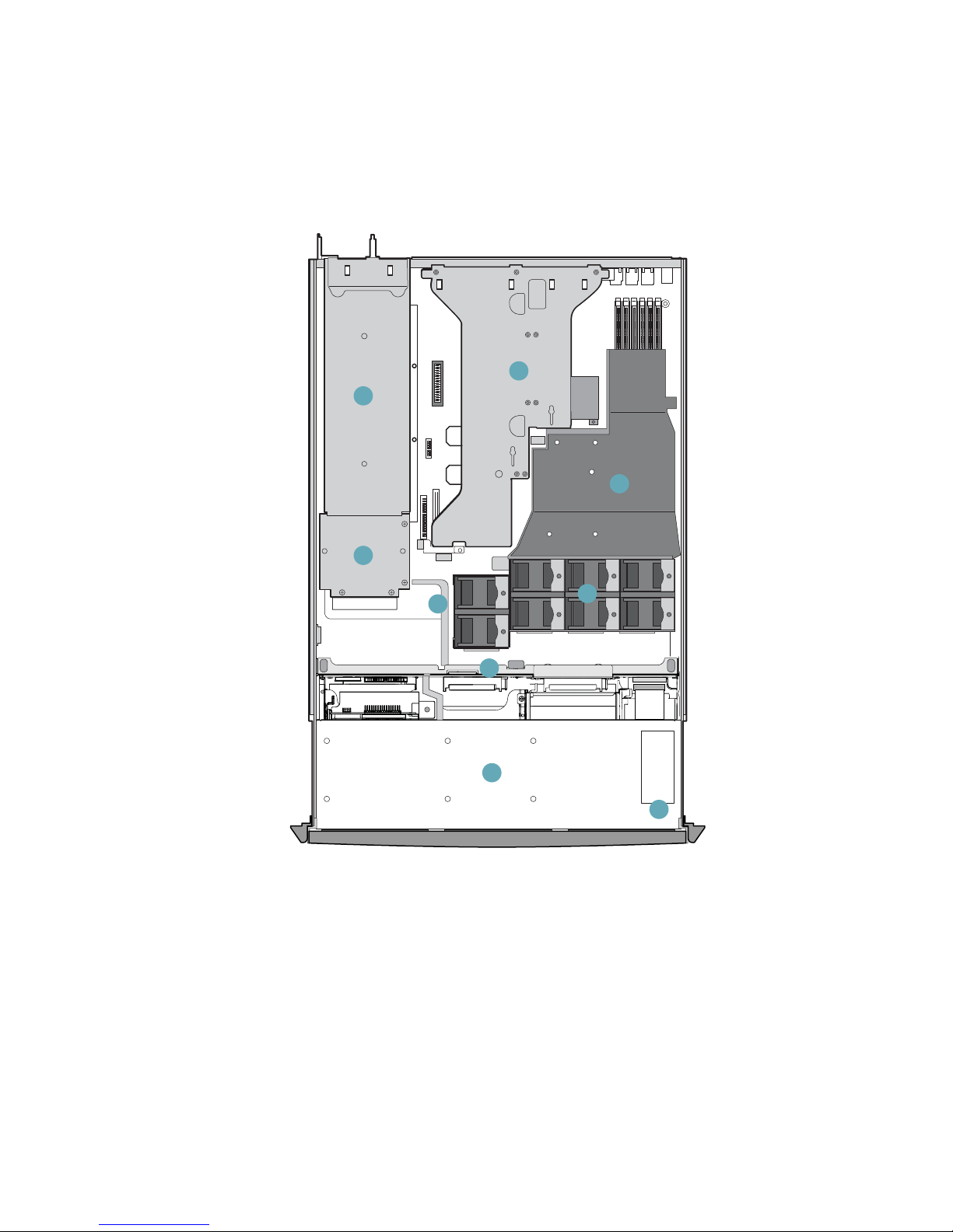
Internal Components
A
C
D
B
E
F
G
H
I
TP01087
A. Power supply module housing F. Fan module (shown with optional redundant fans)
B. Power distribution module G. SATA or SCSI backplane (optional component)
C. PCI Riser assembly H. Drive bay area (drives not included)
D. Processor air duct. (Memory DIMMs and
processor(s) underneath)
E. Air baffle (AC model; air baffle for DC model
differs)
Figure 2. Internal Component Locations
I. Control panel board
4
Page 29
Server Chassis Features
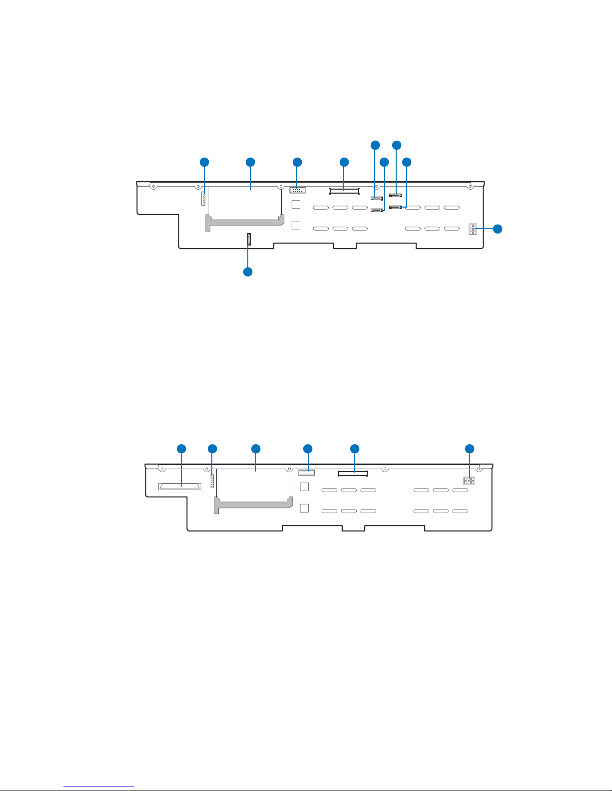
Hot-Swap SATA Backplane Connections
The diagram below shows the connection points on the rear of the SATA backplane. The power
supply, server board and a SATA RAID card can be connected to the locations below.
EGF
A C
A. OPT connector F. SATA channel B connector
B. Location for sixth drive board (accessory) G. SATA channel C connector
C. Fan distribution cable connector H. SATA channel A connector
D. Flex cable connector I. Backplane power connector
E. SATA channel D connector J. SATA channel E connector
B D
J
Figure 3. Rear of SATA Backplane
H
TP01363
I
Hot-Swap SCSI Backplane Connections
The diagram below shows the connection points on the rear of the SCSI backplane. The power
supply, server board and a SCSI RAID card can be connected to the locations below.
A B D E FC
A. SCSI connector D. Fan distribution cable connector
B. OPT connector E. Flex cable connector
C. Location for sixth drive board (accessory) F. Backplane power connector
Figure 4. Rear of SCSI Backplane
TP01364
Intel® Server Chassis SR2400/SR2400DC User Guide 5
Page 30
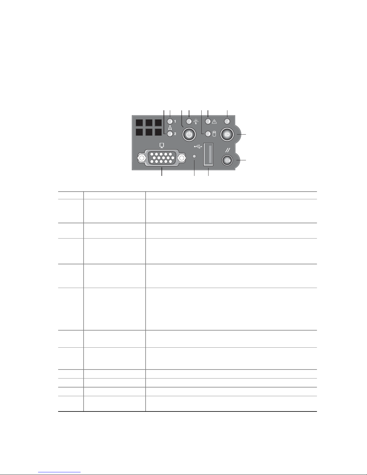
Standard Control Panel
The diagram below shows the features available on the Standard Control Panel. The Standard
Control Panel is one of two required control options that can be selected. The other option is the
®
Intel
Local Control Panel. For instructions on installing the Standard Control Panel, see
“
Replacing the Control Panel.”
BA F GEDC
H
I
L JK
TP00779
Callout Feature Function
A
B
C Power/Sleep button Toggles the system power on/off. Sleep button for ACPI-compatible
D Power/Sleep LED Continuous green light indicates the system has power applied to it.
E Hard disk drive
F System Fault LED Solid green indicates normal operation.
G System Identification
H System identification
I Reset button Reboots and initializes the system.
J USB 2.0 port Allows you to attach a USB component to the front of the chassis.
K NMI button Puts the server in a halt-state for diagnostic purposes.
L Video port Allows you to attach a video monitor to the front of the chassis. The
NIC 2 activity LED
NIC 1 activity LED
activity LED
LED
button
Blinking green light indicates network activity.
Continuous green light indicates a link between the system and the
network to which it is connected.
operating systems.
Blinking green indicates the system is in S1 sleep state.
No light indicates the power is off / is in ACPI S4 or S5 state.
Random blinking green light indicates hard disk drive activity (SCSI
or SATA).
No light indicates no hard disk drive activity.
Blinking green indicates degraded performance.
Solid amber indicates a critical or non-recoverable condition.
Blinking amber indicates a non-critical condition.
No light indicates POST is running or the system is off.
Solid blue indicates system identification is active.
No light indicates system identification is not activated.
Toggles the front panel ID LED and the baseboard ID LED on and
off. The baseboard LED is visible from the rear of the chassis and
allows you to locate the server from the rear of a rack of systems.
front and rear video ports cannot be used at the same time.
6
Figure 5. Standard Control Panel
Page 31

Server Chassis Features
Intel® Local Control Panel
The diagram below shows the features available on the Intel® Local Control Panel. The Intel Local
Control Panel is one of two required control options that can be selected. The other option is the
Standard Control Panel. For instructions on installing the Standard Control Panel, see “
the Control Panel”.
✏ NOTE
This control panel requires the installation of the Intel® Management
Module, Professional Edition or Advance Edition. Some server boards do not
support this control panel. See your server board documentation to determine
if this control panel is compatible with your server board.
BA
C
D
E
F
Replacing
M L K J HIN G
TP00780
Callout Feature Function
A USB 2.0 ports Allows you to attach a USB component to the front of the chassis.
B LCD display Screen on which system information is displayed.
C Menu control button,
scroll up
D Menu control button,
scroll down
E Menu control button,
scroll left
F Menu control button,
scroll right
G System Identification
LED
H Power/Sleep LED Continuous green light indicates the system has power applied to it.
I Power/Sleep button Toggles the system power on/off. Sleep button for ACPI-compatible
Scroll up one option at a time.
Scroll down one option at a time.
Move to the previous option.
Move to the previous page.
Solid blue indicates system identification is active.
No light indicates system identification is not activated.
Blinking green indicates the system is in S1 sleep state.
No light indicates the power is off / is in ACPI S4 or S5 state.
operating systems.
Continued
Intel® Server Chassis SR2400/SR2400DC User Guide 7
Page 32

J System Status LED Solid green indicates normal operation.
L
K
M Hard disk drive
N Reset button Reboots and initializes the system.
NIC 1 activity LED
NIC 2 activity LED
status LED
Back Panel Features
Blinking green indicates degraded performance.
Solid amber indicates a critical or non-recoverable condition.
Blinking amber indicates a non-critical condition.
No light indicates POST is running or the system is off.
Continuous green light indicates a link between the system and the
network to which it is connected.
Blinking green light indicates network activity.
Random blinking green light indicates hard disk drive activity (SCSI
or SATA).
No light indicates no hard disk drive activity.
Figure 6. Intel® Local Control Panel
A B
C
D
E
F
A. Low-profile add-in card bracket
B. Full-height add-in card bracket
C. Grounding studs F. I/O ports (see note)
Notes:
(1) I/O connectors vary, depending on the server board installed. See your server board documentation for port
identification.
(2) AC back panel shown; DC back panel differs.
Figure 7. Chassis Back
D. AC power receptacles (top
receptacle for optional redundant
power supply)
E. Power supply fans (shown
with optional power module
installed)
AF00638
8
Page 33

Server Chassis Features
Peripheral Devices
The chassis provide locations and hardware for installing hard drives, a floppy drive, CD-ROM
drive, or DVD-ROM drive, and a bay for installing a tape drive. The drives must be purchased
separately. The following figure shows the available options.
A
E
B
C
D
A. Slimline floppy drive / DVD / CD-ROM drive bay
B. Tape drive bay (optional kit required). See note below.
C. Sixth drive bay (optional kit required) or merged with tape drive bay (see note below)
D. Hard drive bays (four of five, see letter “E” for the fifth drive bay)
E. Fifth hard drive bay or bay for installing floppy drive conversion kit (optional kit
required)
Note: When a tape drive is installed, it encompasses both the tape drive bay and the
sixth drive bay. You cannot install both a tape drive and a sixth drive.
Figure 8. Optional Peripherals
Hard Disk Drives
The Intel® Server Chassis SR2400/SR2400DC supports both a hot-swap (SCSI and SATA) and a
non-hot-swap (SATA only) configuration. If the non-hot-swap configuration is used, before
replacing a hard drive, you must first take the server out of service, turn off all peripheral devices
connected to the system, turn off the system by pressing the power button, and unplug the AC
power cord or DC external source from the system or wall outlet.
TP01091
The left top drive bay (directly under the slimline bay) can be converted to be used for a floppy
drive. To use the bay for a floppy drive, the AXXFLOPHDDTRAY accessory kit must be used.
For information on how to install a hard drives, see “
✏ NOTES
Drives can consume up to 17 watts of power each. Drives must be specified
to run at a maximum ambient temperature of 45°C.
The Intel Server Chassis SR2400/SR2400DC does not support all SCSI or
Serial ATA hard drives. See “
Internet link to a list of supported hardware.
Intel® Server Chassis SR2400/SR2400DC User Guide 9
Installing and Removing a Hard Disk Drive.”
Additional Information and Software” for an
Page 34

Floppy / CD-ROM / DVD-ROM Drives
The slimline drive carriers included with your server chassis can be used with one slimline floppy,
CD-ROM or DVD-ROM drives. There are two carriers that ship with the chassis. One carrier is
for a CD-ROM or DVD ROM; the other is for a slimline floppy.
The floppy drive / CD-ROM / DVD-ROM cage can be inserted or removed only when
system power is turned off. Drives in the slimline cage are NOT hot swappable. For installation
instructions for a floppy drive, see “
instructions for a CD-ROM or DVD-ROM drive, see “
ROM Drive.”
Installing or Removing a Floppy Drive.” For installation
Installing or Removing a CD-ROM or DVD-
✏ NOTES
The optional kit to convert a hard drive bay to a floppy drive bay must be
used if both a CD-ROM / DVD-ROM drive and a floppy drive are needed.
The Intel Server Chassis SR2400 does not support all slimline floppy, CDROM or DVD-ROM hard drives. See “
for an Internet link to a list of supported hardware. Intel provides accessory
kits for these drives. To use one of the drives provided by Intel, use the
following order codes:
Slimline CD-ROM Drive: AXXSCD
Slimline DVD/CDR Drive: AXXDVDCDR
Slimline Floppy Drive: AXXSFLOPPY
Additional Information and Software”
Tape Drive
A SCSI tape drive can be installed into the combined tape drive bay and the sixth drive bay at the
upper right side of the chassis. If a tape drive is installed, the sixth drive kit cannot be installed; the
tape drive installation merges the two bays into one to accommodate the height of a tape drive.
The carrier to install a tape drive is an optional accessory kit that must be purchased separately. The
order number is ADRTAPEKIT. A tape drive is not included with the accessory kit. For
instructions on installing a tape drive, see “
Installing a Tape Drive.”
10
Page 35

Server Chassis Features
Advanced Management Options
Intel® Management Module
Two versions of the Intel® Management Module are available to provide additional server
management features.
The Intel Management Module - Professional Edition contains a hardware mezzanine card that
plugs into the server board.
The Intel Management Module - Advanced Edition includes a hardware mezzanine card,
10/100 Mb NIC mezzanine card, and cables.
For installation instructions on installing either Intel Management Module, see the instructions
provided with the management module.
✏ NOTE
Some server boards may not support the Intel® Management Module. See
your server board documentation to determine if this feature is compatible
with your server board.
Rack-Mounted Systems
Your Server Chassis SR2400 is designed to be mounted into a rack. The Intel SR2400 server
chassis can be mounted using one of two accessories; the first is a tool-less rail kit and the second is
a fixed rail kit. When installing the chassis into a rack, Intel recommends you install systems from
the bottom of the rack to the top. In other words, install the first system in the rack into the bottom
position of the rack, the second system in the second position from the bottom, and so on.
Instructions for installing your chassis into a rack are included in the rail kit.
The order numbers are as follows:
Tool-less Rail Kit: AXXHERAIL
Fixed Rail Kit: AXXBRACKETS
Cable Management Arm: AXXRACKCARM (requires the tool-less rail kit)
Front Bezels
The optional front bezels provide a snap-on design that allows for maximum airflow through the
server chassis. Two bezels are available. One fits a system that has the Standard Control Panel
installed. The other is used for a chassis with the other Intel Local Control Panel. Each bezel
provides a lock to secure the hard drive and floppy drive / CD-ROM / DVD-ROM drive area. For
instructions on installing either of the front bezels, see “
The order numbers for the bezels are:
Black bezel for use with the Standard Control Panel: ADRBEZBLACK
Black bezel for use with the Intel
®
Local Control Panel: ADRLCDBEZEL
Removing and Installing the Front Bezel”.
Intel® Server Chassis SR2400/SR2400DC User Guide 11
Page 36

12
Page 37

Hardware Installations and Upgrades
2 Hardware Installations and Upgrades
Before You Begin
Before working with your server product, pay close attention to the safety instructions at the
beginning of this manual. See “
This document provides instructions for adding and replacing chassis components. For instructions
on replacing components on the server board, such as the processor and memory DIMMs, see the
instructions provided with the server board.
Tools and Supplies Needed
Phillips* (cross head) screwdriver (#1 bit and #2 bit)
Antistatic wrist strap and conductive foam pad (recommended)
Safety Information.”
System References
All references to left, right, front, top, and bottom and are based on the reader facing the front of the
chassis as it would be positioned for normal operation.
Intel® Server Chassis SR2400/SR2400DC User Guide 13
Page 38

Removing and Installing the Chassis Cover
Removing the Chassis Cover
The Intel® Server Chassis SR2400/SR2400DC must be operated with the top cover in place to
ensure proper cooling. You will need to remove the top cover to add or replace components inside
of the chassis. Before removing the top cover, power down the server and unplug all peripheral
devices and the AC power cable or DC external source. Except for the redundant power supply,
none of the components inside the chassis are hot-swappable.
NOTE
A nonskid surface or a stop behind the chassis may be needed to prevent the
chassis from sliding on your work surface.
1. Observe the safety and ESD precautions at the beginning of this book. See “
Information.”
2. Turn off all peripheral devices connected to the server. Turn off the server.
3. Disconnect the AC power cord or DC external source.
4. Remove the shipping screw (if installed). See letter “A” in the figure below.
5. While holding in the blue button at the top of the chassis in (see letter “B”), slide the top cover
back until it stops (see letter “C”).
6. Lift the cover upward and remove it. A notch in the cover is provided to help lift it upward to
remove it (see letter “D”).
Safety
C
B
D
Figure 9. Removing the Chassis Cover
A
TP01092
14
Page 39

Hardware Installations and Upgrades
Installing the Chassis Cover
1. Place the cover over the chassis so that the side edges of the cover sit just inside the chassis
sidewalls.
2. Slide the cover forward until it clicks into place. See letter “A” in the figure below.
3. (Optional): Insert the shipping screw at the center of the top cover. See letter “B” in the figure.
4. Reconnect all peripheral devices and the AC power cord or DC external source.
A
B
Figure 10. Installing the Chassis Cover
Intel® Server Chassis SR2400/SR2400DC User Guide 15
Page 40

Removing and Installing the Front Bezel
The front bezels are available as optional accessories for the Server Chassis SR2400. Two front
bezel options are available. One is used for the Standard Control Panel and the other is used with
the Intel
installing a bezel on your chassis, make sure you position it with the control panel area at the top
right.
Removing the Front Bezel
Use the steps below if your system includes either the standard front bezel or the front bezel for the
Intel Local Control Panel.
1. Unlock the bezel.
2. Disconnect any cables attached to the front of the control panel.
3. Pull the bezel out from the chassis.
®
Local Control Panel. The installation steps are the same for both bezels. If you are
16
Figure 11. Removing the Front Bezel
TP01344
Page 41

Hardware Installations and Upgrades
Installing the Front Bezel
Use the steps below if your system includes either the standard front bezel or the front bezel for the
Intel Local Control Panel. The front bezel is optional.
1. At each end of the bezel, line up the center notch on the bezel with the center guide on the rack
handles.
2. Push the bezel onto the front of the chassis until it clicks into place.
3. Connect any necessary cables to the control panel area at the right side of the chassis.
4. (Optional): Lock the bezel.
Figure 12. Installing the Front Bezel
TP01342
Intel® Server Chassis SR2400/SR2400DC User Guide 17
Page 42

Removing and Installing the Processor Air Duct and
Processor Air Dam
Always operate your server chassis with the processor air duct in place. The air duct is required to
maintain proper cooling of the processors.
For instructions on adding or replacing a processor, first remove the processor air duct and the
processor air dam, and then see your server board user guide for instructions on processor
installations and removals. Return to these instructions to reinstall the processor air dam and the
processor air duct after installing your processor and heat sink.
Removing the Processor Air Duct
1. Observe the safety and ESD precautions at the beginning of this book. See “Safety
Information.”
2. Power down the server and unplug all peripheral devices and the AC power cable or DC
external source.
3. Remove the chassis cover. For instructions, see “
4. Lift the processor air duct from its location over the processor socket(s). See the figure below.
Removing the Chassis Cover.”
18
TP01343
Figure 13. Removing the Processor Air Duct
Page 43

Hardware Installations and Upgrades
Installing the Processor Air Duct
1. Observe the safety and ESD precautions at the beginning of this book. See “Safety
Information.”
2. Power down the server and unplug all peripheral devices and the AC power cable or DC
external power.
3. Remove the chassis cover. For instructions, see “
4. If you are installing a second processor, remove the air dam on the underside of the processor
air duct. For instructions, see “
Removing the Processor Air Dam”.
5. If you are removing a second processor, install the air dam on the underside of the air duct. For
instructions, see “
Installing the Processor Air Dam.”
6. Place the processor air duct over the processor socket(s). See the figure below. The front edge
of the air duct should contact the fan module and the top of the installed air duct should be flush
with the top surface of the power supply. Use caution not to pinch or disengage cables that may
be near or under the air duct.
Removing the Chassis Cover.”
7. Install the chassis cover. For instructions, see “Installing the Chassis Cover.”
8. Plug in all peripheral devices and connect the AC power cable or DC external source to the
server.
Intel® Server Chassis SR2400/SR2400DC User Guide 19
TP01116
Figure 14. Installing the Processor Air Duct
Page 44

Removing the Processor Air Dam
If you install only a single processor, the processor air dam must be installed on the underside of
the processor air duct. If you install two processors, the air dam must be removed from the air duct.
For instructions on adding or replacing a processor, first remove the processor air duct and the
processor air dam, and then see your server board user guide for instructions on processor
installations and removals. Return to these instructions to reinstall the processor air dam and the
processor air duct.
1. Observe the safety and ESD precautions at the beginning of this book. See “
Information.”
2. Power down the server and unplug all peripheral devices and the AC power cable or DC
external source.
3. Remove the chassis cover. For instructions, see “
4. Remove the processor air duct. For instructions, see “
Removing the Chassis Cover.”
Removing the Processor Air Duct.”
5. Turn the processor air duct over to reveal the underside of it.
6. Remove the air dam by sliding the slotted holes from the duct pins. See the figure below. Save
the air dam for future use.
Safety
7. Install the processor air duct. For instructions, see “Installing the Processor Air Duct.”
8. Install the chassis cover. For instructions, see “
9. Plug in all peripheral devices and connect the AC power cable or DC external source to the
server.
20
Figure 15. Installing the Processor Air Dam
Installing the Chassis Cover.”
TP01117
Page 45

Hardware Installations and Upgrades
Installing the Processor Air Dam
The air dam is installed on a server board that supports two processors but only one processor is to
be installed. Remove the air dam only if you will be installing a second processor. If you have
removed the second processor from the server, install the processor air dam as follows:
1. Observe the safety and ESD precautions at the beginning of this book. See “
Information.”
2. Power down the server and unplug all peripheral devices and the AC power cable or DC
external source.
3. Remove the chassis cover. For instructions, see “
4. Remove the processor air duct. For instructions, see “
5. Turn the processor air duct over to reveal the underside of it.
6. Install one end of the air dam by sliding the slotted holes onto the matching pins in the air duct.
7. Install the opposite end of the air dam, while holding the center of the air dam out, so it pushes
away from the air duct.
8. Install the processor air duct. For instructions, see “
9. Install the chassis cover. For instructions, see “
10. Plug in all peripheral devices and connect the AC power cable or DC external source to the
server.
Removing the Chassis Cover.”
Removing the Processor Air Duct.”
Installing the Processor Air Duct.”
Installing the Chassis Cover.”
Safety
Removing and Installing the Air Baffles
Some installation processes will require that you remove the air baffle(s). Depending on your server
configuration, you will have either one or two air baffles. If your system uses a hot-swap
backplane, you have two air baffles:
A small air baffle is attached to the drive cage area, in front of the backplane.
A large air baffle is installed between the power supply and the back of the backplane. The
large air baffle differs, depending upon whether you have an AC or a DC model of the server
chassis.
If your system uses fixed drives, you have one air baffle that is attached between the power supply
and the drive cage area.
The steps below describe how to remove and then install the air baffle(s). Use these steps only
when it is indicated as necessary for a component installation process. Always operate your server
chassis with the air baffle(s) in place. Air baffles are required for proper airflow within the chassis.
Intel® Server Chassis SR2400/SR2400DC User Guide 21
Page 46

Removing the Large Hot-swap Air Baffle (Backplane Installed)
1. Observe the safety and ESD precautions at the beginning of this book. See “Safety
Information.”
2. Power down the server and unplug all peripheral devices and the AC power cable or DC
external source.
3. Remove the chassis cover. For instructions, see “
4. Important: Note how the cables are routed around and under the air baffle. You will need to
re-route these cables when you re-install the baffle.
5. Pull up on the air baffle to remove it. See the figure below. You may need to remove or hold
cables out of the way.
6. Return to the procedure that directed you to remove the large air baffle.
Removing the Chassis Cover.”
22
TP01347
* Air baffle for AC model shown; air baffle for DC model differs.
Figure 16. Removing the Large Hot-swap Air Baffle
Page 47

Hardware Installations and Upgrades
Installing the Large Hot-swap Air Baffle (Backplane Installed)
1. Observe the safety and ESD precautions at the beginning of this book. See “Safety
Information.”
2. Power down the server and unplug all peripheral devices and the AC power cable or DC
external source.
3. Remove the chassis cover. For instructions, see “
4. Lower the baffle into the chassis between the power supply and the back of the backplane,
using your notes from the air baffle removal steps to re-route the cables.
5. Line up the guide pin on the chassis floor with the matching hole in the baffle. See letter “A” in
the figure below.
6. Push down on the baffle to secure it to the chassis. Use caution so you do not pinch any cables
under the baffle.
7. Return to the procedure that directed you to install the large air baffle.
Removing the Chassis Cover.”
A
* Air baffle for AC model shown; air baffle for DC model differs.
Figure 17. Installing the Large Hot-swap Air Baffle
Intel® Server Chassis SR2400/SR2400DC User Guide 23
Page 48

Removing the Small Hot-swap Air Baffle (Backplane Installed)
1. Observe the safety and ESD precautions at the beginning of this book. See “Safety
Information.”
2. Power down the server and unplug all peripheral devices and the AC power cable or DC
external source.
3. Remove the chassis cover. For instructions, see “
4. Remove the large air baffle. For instructions, see “
(Backplane Installed).”
5. Remove the fan module. For instructions, see “
6. Remove the SATA or SCSI backplane. For instructions, see “
Backplane.”
7. Important: Note how cables are routed around and under the air baffle. You will need to reroute these cables when you reinstall the air baffle.
8. Pull up on the air baffle to remove it, disengaging the hooks that attach the baffle at the rear of
the drive bay area. See letter “A” in the figure below. You may need to remove or hold cables
out of the way.
9. Return to the procedure that directed you to remove the small air baffle.
Removing the Chassis Cover.”
Removing the Large Hot-swap Air Baffle
Removing the Fan Module.”
Removing a SATA or SCSI
Figure 18. Removing the Small Hot-swap Air Baffle
24
TP01348
Page 49

Hardware Installations and Upgrades
Installing the Small Hot-swap Air Baffle (Backplane Installed)
1. Observe the safety and ESD precautions at the beginning of this book. See “Safety
Information.”
2. Power down the server and unplug all peripheral devices and the AC power cable or DC
external source.
3. Remove the chassis cover. For instructions, see “
4. Remove the fan module. For instructions, see “
5. Remove the backplane. For instructions, see “
6. Lower the small baffle into the chassis behind the drive bay area, using your notes from the air
baffle removal steps to re-route any cables.
7. Insert the two hooks on the baffle into the matching slots at the rear of the drive area. See letter
“A” in the figure below.
Removing the Chassis Cover.”
Removing the Fan Module.”
Removing a SATA or SCSI Backplane.”
Figure 19. Installing the Small Hot-swap Air Baffle
8. Install the backplane. For instructions, see “Installing a Replacement SATA or SCSI
Backplane.”
9. Install the fan module. For instructions, see “
10. Return to the procedure that directed you to install the small air baffle.
Intel® Server Chassis SR2400/SR2400DC User Guide 25
Installing the Fan Module.”
Page 50

Removing the Fixed Drive Air Baffle (No Backplane Installed)
1. Observe the safety and ESD precautions at the beginning of this book. See “Safety
Information.”
2. Power down the server and unplug all peripheral devices and the AC power cable or DC
external source.
3. Remove the chassis cover. For instructions, see “
4. Important: Note how the cables are routed over and under the air baffle. You will need to re-
route these cables when you re-install the air baffle.
5. Pull up on the rear of the air baffle and slide the front of the baffle from beneath the drive cage
area to remove it. See the figure below. You may need to remove or hold cables out of the way.
6. Return to the procedure that directed you to remove the fixed drive air baffle.
Removing the Chassis Cover.”
TP01367
* Air baffle for AC model shown; air baffle for DC model differs.
Figure 20. Removing the Fixed Drive Air Baffle
26
Page 51

Hardware Installations and Upgrades
Installing the Fixed Drive Air Baffle (No Backplane Installed)
1. Observe the safety and ESD precautions at the beginning of this book. See “Safety
Information.”
2. Power down the server and unplug all peripheral devices and the AC power cable or DC
external source.
3. Remove the chassis cover. For instructions, see “
4. Hook the front of the air baffle under the drive bay area at the left of the fan module, engaging
the two small hooks at the front of the air baffle. See letter “A” in the figure below.
5. Lower the baffle into the chassis behind the drive bay area, using your notes from the air baffle
removal steps to re-route any cables. See letter “B” in the figure below.
6. Line up the guide pin on the chassis floor with the matching hole in the baffle. See letter “C” in
the figure.
7. Push down on the baffle to secure it to the chassis. Use caution so you do not pinch any cables
under the baffle.
8. Return to the procedure that directed you to install the fixed drive air baffle.
Removing the Chassis Cover.”
B
A
* Air baffle for AC model shown; air baffle for DC model differs.
Figure 21. Installing the Fixed Drive Air Baffle
C
TP01368
Intel® Server Chassis SR2400/SR2400DC User Guide 27
Page 52

Removing and Installing the Fan Module
Some installation processes will require that you remove and later re-install the fan module. The
steps below describe how to remove and then install this component. Use these steps only when it is
indicated as necessary for a component installation process.
Removing the Fan Module
1. Observe the safety and ESD precautions at the beginning of this book. See “Safety
Information.”
2. Power down the server and unplug all peripheral devices and the AC power cable or DC
external source.
3. Remove the chassis cover. For instructions, see “
4. Disconnect the fan module cable from the fan module.
5. Pull up on the release tab at the left side of the fan module to release it from the chassis. See
letter “A” in the figure below.
6. Slide the fan module to the left until it stops.
7. Lift the module from the chassis floor. See letter “B” in the figure.
8. (Hot-swap systems only): Disconnect the fan distribution cable from the backplane.
9. Remove the fan module from the chassis.
Removing the Chassis Cover.”
B
Figure 22. Removing the Fan Module
A
TP01183
28
Page 53

Hardware Installations and Upgrades
Installing the Fan Module
1. Observe the safety and ESD precautions at the beginning of this book. See “Safety
Information.”
2. Power down the server and unplug all peripheral devices and the AC power cable or DC
external source.
3. Remove the chassis cover. For instructions, see “
4. (For hot-swap system only): Attach the fan distribution cable between the backplane and the
fan module. See letters “A” and “B” in the figure below.
Removing the Chassis Cover.”
B
A
Figure 23. Connecting the Fan Distribution Cable
TP01080
Intel® Server Chassis SR2400/SR2400DC User Guide 29
Page 54

5. Place the fan module over the chassis standoffs and slide the module to the right until the blue
tab clicks into place. See letter “A” in the figure below.
6. Connect the folded fan module ribbon cable to the fan module. See letter “B” in the figure.
7. If it is not already connected, connect the other end of the ribbon cable to the server board. See
letter “C” in the figure.
B
C
A
Figure 24. Installing the Fan Module
TP01081
30
Page 55

Hardware Installations and Upgrades
Installing and Removing a Hard Disk Drive
Up to six hard drives of one of the following types can be installed, depending on the hard drive
installation options used in your server chassis and the drives supported by your server board.
Five hot-swap SATA drives if the SATA backplane is installed.
Five hot-swap SCSI drives if the SCSI backplane is installed.
Three fixed SATA drives if the fixed drive kit is installed.
Six hot-swap SATA drives if both the SATA backplane and the sixth drive kit are installed.
Six hot-swap SCSI drives if both the SCSI backplane and the sixth drive kit are installed.
NOTE
The Intel Server Chassis SR2400 does not support all hard drives. See
Additional Information and Software” for an Internet link to a list of
“
supported hardware.
Removing a SATA or SCSI Hot-swap Hard Disk Drive
Use these instructions only if you have installed the SATA or SCSI backplane kit.
1. Remove the front bezel if it is installed. For instructions, see “
2. Press in on the green latch at the front of the hard drive carrier. See letter “A” in the figure
below.
3. Pull out on the black lever and slide the carrier from the chassis. See letter “B” in the figure
below.
B
Figure 25. Removing the Hot-swap Hard Drive Carrier from the Chassis
Removing the Front Bezel.”
A
TP00786
Intel® Server Chassis SR2400/SR2400DC User Guide 31
Page 56

4. Remove the four screws that attach the plastic retention device or the previously installed hard
drive to the drive carrier. Two screws are at each side of the retention device or the hard drive.
If required, store the plastic retention device for future use.
A
TP00787
Figure 26. Removing the Retention Device from the Hot-swap Drive Carrier
Installing a SATA or SCSI Hot-swap Hard Disk Drive
1. Remove the hard drive from its wrapper and place it on an antistatic surface.
2. Set any jumpers and/or switches on the drive according to the drive manufacturer’s
instructions.
3. With the drive circuit-side down, position the connector end of the drive so that it is facing the
rear of the drive carrier.
4. Align the holes in the drive to the holes in the drive carrier and attach it to the carrier with the
screws that were attached to the plastic retention device.
Figure 27. Attaching a Hot-swap Hard Disk Drive to a Drive Carrier
32
TP00736
Page 57

Hardware Installations and Upgrades
5. With the black lever in the fully open position, slide the drive assembly into the chassis. The
green latch at the front of the drive carrier must be to the right. See letter “A” in the figure
below. Do not push on the black drive carrier lever until the lever begins to close by itself.
6. When the black drive carrier lever begins to close by itself, push on it to lock the drive
assembly into place. See letter “B” in the figure.
A
B
TP00789
Figure 28. Inserting a Hot-swap Hard Disk Drive Assembly into the Chassis
Intel® Server Chassis SR2400/SR2400DC User Guide 33
Page 58

7. (SATA installation only): Connect the SATA cable(s) labeled SATA CH A and SATA CH B to
the backplane. See letter “A” in the figure below to locate the backplane. See letter “B” in the
figure to identify the end of the SATA cable that is attached to the backplane. In the figure
below, the SATA board showing the SATA cable connections is shown as if you were looking
at the chassis from the rear.
8. (SATA installation only): If you will be using the SATA connections on the server board,
connect the 90-degree end of the SATA cable(s) to the corresponding server board
connection(s). The cable connected to SATA CH A should be connected to SATA 0. The cable
connected to SATA CH B should be connected to SATA 1. See letter “C” in the figure below
to identify the end of the SATA cable that is attached to the server board. See your server board
documentation to locate the SATA connection points on the server board.
If you will be using an add-in SATA RAID controller, connect SATA CH A through SATA
CH E to the appropriate connectors on the add-in card. See your add-in card documentation for
the appropriate SATA connections.
S ATA
S ATA
C
S ATA
CH C
S ATA
CH D
CH B
CH A
A
A
S ATA
CH E
Figure 29. Connecting the Hot-swap SATA Data Cables
B
TP01365
34
Page 59

Hardware Installations and Upgrades
9. (SCSI installation only): Connect the end of the SCSI cable that is labeled “Backplane” to the
backplane SCSI Connector. See letter “A” in the figure below.
10. (SCSI installation only): Connect the end of the SCSI cable that is labeled “Server Board” to
the SCSI connection on the server board if not already connected. See letter “B” in the figure
below. See your server board documentation to locate the SCSI connection point on the server
board.
B
A
TP01075
Figure 30. Connecting the SCSI Data Cable
11. (Optional) Install the front bezel. For instructions, see “Installing the Front Bezel.”
Intel® Server Chassis SR2400/SR2400DC User Guide 35
Page 60

Installing a Fixed SATA Hard Disk Drive
Use these instructions only if you have installed the fixed drive kit.
CAUTION
Fixed drives are NOT hot swappable. Before removing or replacing the
drive, you must first take the server out of service, turn off all peripheral
devices connected to the system, turn off the system by pressing the power
button, and removing the AC power cord or DC external source from the
system or wall outlet.
1. Observe the safety and ESD precautions at the beginning of this book. See “
Information.”
2. Power down the server and unplug all peripheral devices and the AC power cable or DC
external source.
3. Remove the front bezel if it is installed. For instructions, see “
Removing and Installing the
Front Bezel.”
4. Remove the chassis cover. For instructions, see “
Removing the Chassis Cover.”
5. Press the latch on the back of the fixed drive carrier and slide the carrier from the bay. See
letter “A” in the figure below to identify the latch at the rear of the carrier.
Safety
Figure 31. Removing a Fixed Hard Drive Carrier from the Chassis
36
A
TP01354
Page 61

Hardware Installations and Upgrades
6. Remove the four screws that attach the plastic retention device or the previously installed hard
drive to the drive carrier. Two screws are at each side of the retention device or the hard drive.
If required, store the plastic retention device for future use.
TP01304
Figure 32. Removing the Retention Device from the Fixed Drive Carrier
7. With the drive circuit-side down, position the connector end of the drive so that it is facing the
back of the carrier.
8. Attach the hard drive to the carrier using the four screws removed from the carrier.
A
TP00788
Figure 33. Attaching a Hard Drive to the Fixed Drive Carrier
Intel® Server Chassis SR2400/SR2400DC User Guide 37
Page 62

9. Insert the drive into the bay until it clicks into place. Install drives first into the lower three
drive bays for the easiest cable routing.
10. If it is not already installed, connect the SATA power cable adapter to the 3x2 power supply
cable that extends from your power supply. See letters “A” and “B” in the figure below. The
power cable adapter was provided to you with the fixed drive kit.
B
A
TP01161
Figure 34. Installing the Fixed SATA Drive Power Cables
38
Page 63

Hardware Installations and Upgrades
11. For each drive you install, route one SATA data cable from the server board or add-in card to
the hard drive, with the right-angle end of the SATA data cable connected to the server board
or add-in card SATA connector. See letter “B” in the figure below and see your server board
documentation or add-in card documentation for assistance in locating the SATA connectors on
the board or add-in card.
12. See letters “C” and “D” in the following figure and the arrow that leads from these letters to the
component in the chassis. This component is the air baffle that is referred to in the following
steps. The letters “C” and “D” point to the cutouts that are referred to in the step below.
13. Data cables for drives installed to the right of the air baffle must be routed through the two
cutouts at the bottom of the air baffle (letters “C” and “D” in the figure). The data cable for
drives installed to the left of the air baffle must be routed through the rear cutout of the air
baffle (letter “D”). You may need to remove the air baffle to route the cables underneath it. To
see how to remove and then install the air baffle, see “
(No Backplane Installed)” and “
Installing the Fixed Drive Air Baffle (No Backplane
Removing the Fixed Drive Air Baffle
Installed).”
14. Connect the remaining end of the SATA data cable to the back of the SATA drive. See letter
“A” in the figure below.
A
B
D
C
* Air baffle for AC model shown; air baffle for DC model differs.
Figure 35. Installing the Fixed SATA Drive Data Cables
A
TP01324
Intel® Server Chassis SR2400/SR2400DC User Guide 39
Page 64

15. Power cables for drives installed to the right side of the air baffle must be routed beneath the
front cutout in the underside of the air baffle. See letter “B” in the figure below. The power
cables for drives installed to the left of the air baffle do not need to be routed under the air
baffle. You may need to remove the air baffle to route cables underneath it. To see how to
remove and then install the air baffle, see “
Backplane Installed)” and “
Installing the Fixed Drive Air Baffle (No Backplane Installed).”.
Removing the Fixed Drive Air Baffle (No
16. Connect the SATA power cable adapter end(s) to the rear of the SATA drive. See letter “A” in
the figure below to locate the connector on the SATA drive.
17. Install the chassis cover. For instructions, see “
18. Install the front bezel. For instructions, see “
Removing the Chassis Cover.”
Removing and Installing the Front Bezel.”
A
B
A
* Air baffle for AC model shown; air baffle for DC model differs.
Figure 36. Installing the Fixed SATA Drive Power Cables
TP01325
40
Page 65

Hardware Installations and Upgrades
Removing a Fixed SATA Hard Disk Drive
CAUTION
Fixed drives are NOT hot swappable. Before removing or replacing the
drive, you must first take the server out of service, turn off all peripheral
devices connected to the system, turn off the system by pressing the power
button, and remove the AC power cord or DC external source from the
system or wall outlet.
1. Observe the safety and ESD precautions at the beginning of this book. See “
Information.”
2. Power down the server and unplug all peripheral devices and the AC power cable or DC
external source.
3. Remove the chassis cover. For instructions, see “
4. Remove the front bezel if it is installed. For instructions, see “
Front Bezel.”
5. Disconnect the SATA data connector and power cables from the rear of the SATA drive and
remove the SATA data cables. You may need to remove and then reinstall the air baffle to
remove the SATA cables from the chassis. For instructions, see “
Baffle (No Backplane Installed)” and “
Installed).”
6. Press the latch on the back of the fixed drive carrier and slide it from the bay.
7. Remove the four screws that attach the hard drive to the drive carrier. Lift the drive from the
carrier. Store the drive in an anti-static bag.
8. If you are not installing a new drive, place the plastic retention device into the drive carrier,
using the four screws you removed from the hard drive.
9. Insert the screws that held the drive in the carrier into the screw locations on the carrier for
future use.
10. Slide the drive carrier into the chassis until it clicks into place.
Installing the Fixed Drive Air Baffle (No Backplane
Removing the Chassis Cover.”
Removing and Installing the
Removing the Fixed Drive Air
Safety
✏ NOTE
For proper airflow, the hard drive carrier must be replaced in the chassis,
even if no hard drive is installed in it.
11. (Optional) Install the front bezel. For instructions, see “
Bezel.”
12. Install the chassis cover. For instructions, see “
13. Plug in all peripheral devices and connect the AC power cable or DC external source to the
server.
Intel® Server Chassis SR2400/SR2400DC User Guide 41
Removing and Installing the Front
Removing the Chassis Cover.”
Page 66

Installing the SATA or SCSI Sixth Drive Accessory
The SATA and SCSI sixth drive accessories is used when a sixth SATA hot-swap drive or a sixth
SCSI hot-swap drive is needed. The SATA or SCSI backplane accessory kit is required to install
this accessory. After installing the sixth drive accessory kit, see “
swap Hard Disk Drive” for instructions on installing a hot-swap disk drive.
Removing a SATA or SCSI Hot-
✏ NOTE
You cannot use the sixth drive accessory kit to mix installations of SATA
and SCSI drives. In other words, if you have five SCSI drives installed, you
cannot use the sixth drive accessory as a way to install a SATA drive. Your
drive types must match the type of backplane that you have installed.
1. Observe the safety and ESD precautions at the beginning of this book. See “
Information.”
2. Power down the server and unplug all peripheral devices and the AC power cable or DC
external source.
3. Remove the chassis cover. For instructions, see “
4. Remove the front bezel if it is installed. For instructions, see “
5. Remove the drive blank from the sixth drive bay by using a long screwdriver to push it out
through the front of the chassis.
Removing the Chassis Cover.”
Removing the Front Bezel.”
Safety
Figure 37. Remove the Drive Blank from the Chassis
42
TP01366
Page 67

Hardware Installations and Upgrades
6. Remove the fan module. For instructions, see “Removing the Fan Module.”
7. Hold the SATA or SCSI sixth drive accessory board about ¼-inch above the opening in the
backplane to allow alignment notches to clear the top of the backplane bracket. Move the board
forward into the opening and set it into place while lining up the two tabs on the sixth drive kit
board with the matching holes on backplane. Be sure the board seats into the plastic retainer at
the bottom of the backplane opening.
TP01084
Figure 38. Installing the Sixth Drive Board
8. (SATA sixth drive accessory only): Connect the end of the long SATA data cable that has the
right-angle connector to the server board or to the add-in card. See your server board or add in
card documentation for the connection point on the server board or add-in card. Connect the
remaining end of the cable to the connector on the sixth drive board.
9. (SCSI sixth drive accessory only): Connect the end of the long SCSI cable that is labeled
“Backplane” to the connector on the sixth drive board that is labeled “M/B.” Connect the
remaining end of the SCSI connector to the server board or add in card. See server board or add
in card documentation for the connection location. For assistance in locating connectors on the
backplane, see “
Hot-Swap SATA Backplane Connections.”
10. (SCSI sixth drive accessory only): Connect the end of short SCSI cable that is labeled
“Backplane” to the backplane connector labeled “SCSI CH A.” Connect the other end to the
sixth drive board connector. For assistance in locating connectors on the backplane, see “
Hot-
Swap SCSI Backplane Connections.”
Intel® Server Chassis SR2400/SR2400DC User Guide 43
Page 68

11. Included with your sixth drive kit is a power cable connector labeled “Drive 5 Pwr.” Connect
one end of this cable into the connector labeled “OPT” on sixth drive board. Connect the
remaining end of the Drive 5 power cable to the connector on the backplane that is labeled
“OPT CONN.”
12. Install the fan module. For instructions, see “
13. Install the chassis cover. For instructions, see “
14. Install the SATA or SCSI hard disk drive into the sixth drive position. For instructions, see
“
Removing a SATA or SCSI Hot-swap Hard Disk Drive.”
15. (Optional): Install the front bezel. For instructions, see “
Installing the Fan Module.”
Removing the Chassis Cover.”
Installing the Front Bezel.”
Installing or Removing a Floppy Drive (Slimline or
Standard)
Floppy drives are installed in different ways, depending on the following considerations:
The SATA or SCSI backplane is installed and you want to install the floppy drive into the
slimline drive bay.
No backplane is installed and you want to install the floppy drive into the slimline drive bay.
The SATA or SCSI backplane is installed and you have installed a CD-ROM or DVD-ROM
drive into the slimline drive bay. You want to install the floppy drive into a bay that was
intended for a hard drive (optional conversion kit is required).
Look carefully at the heading titles below before beginning your installation to be sure you are
following the correct instructions for your server.
CAUTION
Floppy drives are NOT hot swappable. Before removing or replacing the
drive, you must first take the server out of service, turn off all peripheral
devices connected to the system, turn off the system by pressing the power
button, and remove the AC power cord or DC external source from the
system or wall outlet.
Installing a Floppy Drive into Slimline Bay (Backplane Installed)
Use these instructions if you are installing a floppy drive into the slimline drive bay at the upper left
side of your chassis and your system includes either the SATA or SCSI backplane. You will know
if you have one of these backplanes installed if you can install either hot-swap SATA or hot-swap
SCSI drives.
✏ NOTE
The carrier for the slimline floppy drive that is used in these instructions was
sent to you in the hardware kit that came with your Server Chassis
SR2400/SR2400DC.
44
Page 69

Hardware Installations and Upgrades
1. Observe the safety and ESD precautions at the beginning of this book. See “Safety
Information.”
2. Power down the server and unplug all peripheral devices and the AC power cable or DC
external source.
3. Remove the chassis cover. For instructions, see “
4. Remove the front bezel if it is installed. For instructions, see “
Removing the Chassis Cover.”
Removing the Front Bezel.”
5. Align the two holes at the left side of the floppy drive with the two cutouts in the floppy drive
carrier. See letter “A” in the figure below.
6. Lower the right side of the floppy drive into the carrier until it clicks into place. See letter “B”
in the figure below.
A
B
TP01082
Figure 39. Installing a Floppy Drive into the Slimline Carrier
7. Open the connector on the rear of the floppy drive by pulling up on the connector cover. See
letter “A” in the figure below.
8. Insert one end of the 26-pin floppy drive flat flex cable end into the connector. See letter “B” in
the figure.
9. Push down on the connector cover to lock the cable into place. See letter “C” in the figure.
A
B
C
Intel® Server Chassis SR2400/SR2400DC User Guide 45
TP01144
Page 70

Figure 40. Connecting the Flat Flex Cable to a Floppy Drive
10. Slide the floppy drive assembly into the slimline bay of the chassis until it clicks into place. See
letter “A” in the figure below.
11. Open the connector labeled “Floppy Con” on the backplane by pulling up on the connector
cover. See letter “B” in the figure below. For assistance in locating connectors on the SATA
backplane, see “
connectors on the SCSI backplane, see “
Hot-Swap SATA Backplane Connections.” For assistance in locating
Hot-Swap SCSI Backplane Connections.”
12. Insert the loose end of the floppy cable into the backplane connector. See letter “C” in the
figure.
13. Push in on the connector cover to lock the cable into place. See letter “D” in the figure.
CC
BB
AA
Figure 41. Installing the Slimline Floppy Drive into the Chassis
DD
14. Install the chassis cover. For instructions, see “Installing the Chassis Cover.”
15. (Optional): Install the front bezel. For instructions, see “
16. Plug in all peripheral devices and connect the AC power cable or DC external source to the
server.
46
Installing the Front Bezel.”
Page 71

Hardware Installations and Upgrades
Removing a Floppy Drive from the Slimline Bay (Backplane
Installed)
1. Observe the safety and ESD precautions at the beginning of this book. See “Safety
Information.”
2. Power down the server and unplug all peripheral devices and the AC power cable or DC
external source.
3. Remove the chassis cover. For instructions, see “
4. Remove the front bezel if it is installed. For instructions, see “
5. Pull up at the top of the connector on the backplane labeled “Floppy Con” to release the cable
from it. For assistance in locating connectors on the SATA backplane, see “
Backplane Connections.” For assistance in locating connectors on the SCSI backplane, see
“
Hot-Swap SCSI Backplane Connections.”
6. Push in on the blue lever at the rear of the drive carrier.
7. Slide the floppy drive carrier out through the front of the chassis.
8. Remove the data cable from the rear of the floppy.
9. Press downward on the side of the carrier to release the drive from the drive carrier.
10. Store the floppy drive carrier and the floppy drive data cable for future use.
11. Install the slimline filler panel into the chassis opening.
12. Install the chassis cover. For instructions, see “Installing the Chassis Cover.”
13. (Optional): Install the front bezel. For instructions, see “
14. Plug in all peripheral devices and connect the AC power cable or DC external source to the
server.
Removing the Chassis Cover.”
Removing the Front Bezel.”
Hot-Swap SATA
Installing the Front Bezel.”
Intel® Server Chassis SR2400/SR2400DC User Guide 47
Page 72

Installing Floppy Drive into Slimline Bay (No Backplane Installed)
✏ NOTE
The carrier for the slimline floppy drive that is used in these instructions was
sent to you in the hardware kit that came with your Server Chassis
SR2400/2400DC. The interposer board and floppy drive power adapter cable
used in these instructions was sent to you with your fixed drive kit.
1. Observe the safety and ESD precautions at the beginning of this book. See “
Information.”
2. Power down the server and unplug all peripheral devices and the AC power cable or DC
external source.
3. Remove the chassis cover. For instructions, see “
4. Remove the front bezel if it is installed. For instructions, see “
Removing the Chassis Cover.”
Removing the Front Bezel.”
5. Align the two holes at the left side of the floppy drive with the two cutouts in the floppy drive
carrier. See letter “A” in the figure below.
6. Lower the right side of the floppy drive into the carrier until it clicks into place. See letter “B”
in the figure below.
Safety
A
B
TP01082
Figure 42. Installing a Slimline Floppy Drive into the Carrier
48
Page 73

Hardware Installations and Upgrades
7. Open the connector on the rear of the floppy drive by pulling up on the connector cover. See
letter “A” in the figure below.
8. Insert one end of the 26-pin flat flex cable end into the connector. See letter “B” in the figure.
9. Push down on the connector cover to lock the cable into place. See letter “C” in the figure.
10. Open the connector on the interposer board by pulling out on the connector cover. See letter
“D” in the figure below.
11. Insert the loose end of the floppy cable into the interposer board connector. See letter “E” in the
figure.
12. Push in on the connector cover to lock the cable into place. See letter “F” in the figure.
Figure 43. Connecting the Flat Flex Cable to a Floppy Drive
Intel® Server Chassis SR2400/SR2400DC User Guide 49
Page 74

13. Lower the interposer board into the floppy drive tray at the rear of the floppy drive and engage
the notch on the board. See letter “A” in the figure below.
14. Attach the interposer board to floppy drive with the screw that was included with the interposer
board. See letter “B” in the figure. In the diagram, the flat flex cable been removed for clarity.
A
Figure 44. Installing the Floppy Drive Interposer Board
B
TP01164
50
Page 75

Hardware Installations and Upgrades
15. Slide the floppy drive assembly into the chassis until it clicks into place. See letter “A” in the
figure below.
16. Connect the 2x2 end of the floppy drive power cable that was included with your kit to the 2x2
power connector on the SATA power adapter cable. See letters “B” and “C” in the figure
below.
17. Connect the remaining end of the floppy drive power cable to the power connector on the rear
of the floppy drive. See letter “D” in the figure.
18. Connect the floppy drive data cable that was included with your kit between the floppy drive
data connector and the server board. See letters “E” and “F” in the figure. See your server board
documentation for assistance in locating the connector location on the server board.
19. Route the floppy drive data cable underneath the air baffle, as shown in the diagram below.
You may need to remove the air baffle to route the data cable. For instructions on removing and
installing the air baffle, see “
Installing the Fixed Drive Air Baffle (No Backplane Installed).”
and “
Removing the Fixed Drive Air Baffle (No Backplane Installed)”
F
A
C
B
E
D
E
D
F
B
C
Intel® Server Chassis SR2400/SR2400DC User Guide 51
Figure 45. Connecting the Floppy Drive Cables
TP01165
Page 76

17. Install the chassis cover. For instructions, see “Installing the Chassis Cover.”
18. Remove the front bezel. For instructions, see “
19. Plug in all peripheral devices and connect the AC power cable or DC external source to the
server.
Installing the Front Bezel.”
Removing a Floppy Drive from the Slimline Bay (No Backplane
Installed)
1. Observe the safety and ESD precautions at the beginning of this book. See “Safety
Information.”
2. Power down the server and unplug all peripheral devices and the AC power cable or DC
external source.
3. Remove the chassis cover. For instructions, see “
4. Remove the front bezel if it is installed. For instructions, see “
5. Detach the power and data cables from the rear of the floppy drive.
6. Detach the data cable from the server board and remove the cable from the chassis. Remove the
data cable from the chassis. You may need to remove the air baffle to remove the data cable.
For instructions on removing and installing the air baffle, see “
Baffle (No Backplane Installed)” and “
Installed).”
7. Push in on the blue lever at the rear of the drive carrier.
8. Slide the floppy drive carrier out through the front of the chassis.
9. Remove the screw that attaches the interposer board to the drive. Lift the interposer board from
the drive.
10. Press downward on the side of the carrier to release the drive from the drive carrier.
11. Store the floppy drive carrier, the interposer board, and the floppy drive data cable for future
use.
12. Install the slimline filler panel into the chassis opening.
13. Install the chassis cover. For instructions, see “
14. (Optional) Install the front bezel. For instructions, see “
Bezel.”
15. Plug in all peripheral devices and connect the AC power cable or DC external source to the
server.
Installing the Fixed Drive Air Baffle (No Backplane
Removing the Chassis Cover.”
Removing the Front Bezel.”
Removing the Fixed Drive Air
Installing the Chassis Cover.”
Removing and Installing the Front
52
Page 77

Hardware Installations and Upgrades
Installing a Floppy Drive into the Converted Hard Drive Bay
(Backplane Installed)
The floppy drive conversion kit can only be installed into a system that is using either the SATA or
the SCSI backplane. The floppy drive conversion kit must be installed in the left, top hard drive
bay, directly under the slimline drive bay.
1. Observe the safety and ESD precautions at the beginning of this book. See “
Information.”
2. Power down the server and unplug all peripheral devices and the AC power cable or DC
external source.
3. Remove the chassis cover. For instructions, see “
4. Remove the front bezel if it is installed. For instructions, see “
Removing the Chassis Cover.”
Removing the Front Bezel.”
5. Remove the upper left hot-swap hard drive carrier from the chassis.
6. Remove the screws that attach the slide rails to the floppy drive conversion kit carrier.
Safety
Figure 46. Removing the Rails from the Floppy Drive Conversion Kit Carrier
Intel® Server Chassis SR2400/SR2400DC User Guide 53
TP01307
Page 78

7. Slide the floppy drive into the drive carrier, rear of the drive first, with the underside of the
drive facing down.
8. Line up the holes in the side of the drive with the holes in the carrier. See letter “A” in the
figure below.
A
A
TP01308
Figure 47. Inserting a Floppy Drive into the Floppy Drive Conversion Kit Carrier
9. Attach the floppy drive to the carrier with the screws that came with your floppy drive
conversion kit. One screw attaches at each side. See the figure below.
TP01323
Figure 48. Attaching a Floppy Drive to the Floppy Drive Conversion Kit Carrier
54
Page 79

Hardware Installations and Upgrades
10. Reattach the slide rails onto floppy drive conversion kit carrier. See the figure below.
TP01309
Figure 49. Installing the Rails onto the Floppy Drive Conversion Kit Carrier
11. Open the connector on the rear of the floppy drive by pulling up on the connector cover. See
letter “A” in the figure below.
12. Insert one end of the flat flex cable end into the floppy drive connector. See letter “B” in the
figure.
13. Push down on the connector cover to lock the cable into place. See letter “C” in the figure.
C
A
Figure 50. Connecting the Flat Flex Cable to a Floppy Drive
B
TP01311
Intel® Server Chassis SR2400/SR2400DC User Guide 55
Page 80

14. Slide the carrier assembly into the upper left hard drive bay until it clicks into place. See letter
“A” in the figure below.
15. Open the connector labeled “Floppy Con” on the backplane by pulling up on the connector
cover. See letter “B” in the figure below. For assistance in locating connectors on the SATA
backplane, see “
connectors on the SCSI backplane, see “
Hot-Swap SATA Backplane Connections.” For assistance in locating
Hot-Swap SCSI Backplane Connections.”
16. Insert the loose end of the flat flex cable into the backplane connector. See letter “C” in the
figure.
17. Push in on the connector cover to lock the cable into place. See letter “D” in the figure.
D
B
C
Figure 51. Installing the Floppy Drive into the Chassis
18. Install the chassis cover. For instructions, see “Installing the Chassis Cover”
19. (Optional) Install the front bezel. For instructions, see “
20. Plug in all peripheral devices and connect the AC power cable or DC external source to the
server.
56
A
TP01310
Installing the Front Bezel.”
Page 81

Hardware Installations and Upgrades
Removing a Floppy Drive from the Converted Hard Drive Bay
1. Observe the safety and ESD precautions at the beginning of this book. See “Safety
Information.”
2. Power down the server and unplug all peripheral devices and the AC power cable or DC
external source.
3. Remove the chassis cover. For instructions, see “
4. Remove the front bezel if it is installed. For instructions, see “
5. Open the connector labeled “Floppy Con” on the backplane by pulling up on the connector
cover. Remove the flat flex cable from the backplane. For assistance in locating connectors on
the SATA backplane, see “
locating connectors on the SCSI backplane, see “
6. Push in on the lever at the rear of the floppy carrier and slide the drive from the front of the
chassis.
7. Open the connector cover on the rear of the floppy drive by pulling up on it. Release the flat
flex cable from the drive.
8. Remove the two screws at each side that hold the drive rails to the drive carrier. Lift the two
rails from the carrier.
9. Disconnect the two screws attaching the drive to the converted hard drive bay carrier.
10. Install an empty hot-swap hard drive carrier into chassis drive bay if no floppy or hard drive is
to be installed into the bay.
11. Store the screws, the converted drive bay carrier, the side rails, and the flat flex cable for future
use.
12. Install the chassis cover. For instructions, see “Installing the Chassis Cover.”
13. (Optional) Install the front bezel. For instructions, see “
14. Plug in all peripheral devices and connect the AC power cable or DC external source to the
server.
Hot-Swap SATA Backplane Connections.” For assistance in
Removing the Chassis Cover.”
Removing the Front Bezel.”
Hot-Swap SCSI Backplane Connections.”
Installing the Front Bezel.”
Installing or Removing a CD-ROM or DVD-ROM Drive
CAUTION
CD-ROM and DVD-ROM drives are NOT hot swappable. Before removing
or replacing the drive, you must first take the server out of service, turn off
all peripheral devices connected to the system, turn off the system by
pressing the power button, and remove the AC power cord or DC external
source from the system or wall outlet.
Intel® Server Chassis SR2400/SR2400DC User Guide 57
Page 82

Installing a DVD-ROM or CD-ROM Drive into Slimline Bay
(Backplane Installed)
✏ NOTE
The carrier for the slimline DVD-ROM drive / CD-ROM drive was preinstalled in the slimline drive bay of your Server Chassis
SR2400/SR2400DC.
1. Observe the safety and ESD precautions at the beginning of this book. See “Safety
Information.”
2. Power down the server and unplug all peripheral devices and the AC power cable or DC
external source.
3. Remove the chassis cover. For instructions, see “
4. Remove the front bezel if it is installed. For instructions, see “
5. Push in on the blue lever at the rear of the CD-ROM / DVD-ROM drive carrier and push the
carrier out through the front of the chassis.
6. Align the two holes at left edge of DVD-ROM /CD-ROM drive with the cutouts in drive
carrier. See letter “A” in the figure below.
7. Lower the right side of the DVD-ROM / CD-ROM drive into the carrier until it clicks into
place. See letter “B” in the figure below.
8. Use the two screws indicated in the figure to attach the interposer board to the DVD-ROM /
CD-ROM drive. See letters “C” and “D” in the figure.
9. Attach the 44-pin CD-ROM drive cable to the exposed side / back of the interposer board. See
letter “E” in the figure.
Removing the Chassis Cover.”
Removing the Front Bezel.”
E
D
D
C
A
Figure 52. Installing a DVD-ROM / CD-ROM Drive into the Slimline Carrier
B
TP01085
58
Page 83

Hardware Installations and Upgrades
10. Slide the DVD-ROM / CD-ROM drive carrier into the chassis. See letter “A” in the figure
below.
11. Connect the loose end of the CD-ROM drive cable to the backplane connector. See letter “B” in
the figure. For assistance in locating connectors on the SATA backplane, see “
Hot-Swap SATA
Backplane Connections.” For assistance in locating connectors on the SCSI backplane, see
“
Hot-Swap SCSI Backplane Connections.”
A
B
TP01086
Figure 53. Installing a DVD/CDROM Drive into the Chassis
12. Install the chassis cover. For instructions, see “
13. (Optional) Install the front bezel. For instructions, see “
Installing the Chassis Cover.”
Installing the Front Bezel.”
14. Plug in all peripheral devices and connect the AC power cable or DC external source to the
server.
Removing a CD-ROM or DVD-ROM Drive from the Slimline Bay
(Backplane Installed)
1. Observe the safety and ESD precautions at the beginning of this book. See “Safety
Information.”
2. Power down the server and unplug all peripheral devices and the AC power cable or DC
external source.
3. Remove the chassis cover. For instructions, see “
4. Remove the front bezel if it is installed. For instructions, see “
5. Disconnect the CD-ROM data cable from the backplane. For assistance in locating connectors
on the SATA backplane, see “
Hot-Swap SATA Backplane Connections.” For assistance in
locating connectors on the SCSI backplane, see “
6. Push in on the blue lever at the rear of the drive carrier. Slide the drive carrier out through the
front of the chassis.
7. Press downward on the side of the carrier release the drive from the drive carrier.
Removing the Chassis Cover.”
Removing the Front Bezel.”
Hot-Swap SCSI Backplane Connections.”
Intel® Server Chassis SR2400/SR2400DC User Guide 59
Page 84

8. Disconnect the data cable from the rear of the CD-ROM or DVD-ROM drive.
9. Remove the two screws at the rear of the CD-ROM or DVD-ROM drive to disconnect the
interposer board.
10. Store the screw and interposer board for future use. Suggestion: tape the screw to the drive
carrier.
11. Install the slimline filler panel in the chassis opening.
12. Install the chassis cover. For instructions, see “
13. (Optional) Install the front bezel. For instructions, see “
14. Plug in all peripheral devices and connect the AC power cable or DC external source to the
server.
Installing the Chassis Cover.”
Installing the Front Bezel.”
Installing a DVD-ROM or CD-ROM Drive into Slimline Bay (No
Backplane Installed)
✏ NOTE
The carrier for the slimline DVD-ROM drive / CD-ROM drive was preinstalled in the slimline drive bay of your Server Chassis
SR2400/SR2400DC. The interposer board and floppy drive power adapter
cable used in these instructions was sent to you with your fixed drive kit.
1. Observe the safety and ESD precautions at the beginning of this book. See “
Information.”
2. Power down the server and unplug all peripheral devices and the AC power cable or DC
external source.
3. Remove the chassis cover. For instructions, see “
4. Remove the front bezel if it is installed. For instructions, see “
5. Push in on the blue lever at the rear of the CD-ROM / DVD-ROM drive carrier and push the
carrier out through the front of the chassis.
6. Align the two holes at left edge of DVD-ROM / CD-ROM drive with the cutouts in drive
carrier. See letter “A” in the figure below.
7. Lower the right side of the DVD-ROM / CD-ROM drive into the carrier until it clicks into
place. See letter “B” in the figure below.
Removing the Chassis Cover.”
Removing the Front Bezel.”
Safety
60
Page 85

Hardware Installations and Upgrades
8. Use the two screws indicated in the figure to attach the interposer board to the DVD-ROM /
CD-ROM drive. See letters “C” and “D” in the figure.
D
D
C
B
A
TP01166
Figure 54. Installing a DVD-ROM or CD-ROM Drive into the Slimline Carrier
9. Insert the DVD-ROM / CD-ROM drive carrier into the chassis. See letter “A” in the figure
below.
10. If it is not already connected, connect the 2x3 end of the DVD-ROM/CD-ROM drive power
cable that was included with your fixed drive kit to the 2x3 power connector on the SATA
power adapter cable. See letters “B” and “C” in the figure below.
11. Connect the drive power cable to the power connector on the rear of the DVD-ROM or
CD-ROM drive. See letter “D” in the figure.
12. Connect the DVD-ROM / CD-ROM drive data cable that was included with your kit between
the interposer board and the IDE connector on the server board. See letters “E” and “F” in the
figure. See your server board documentation for assistance in locating the connector location on
the server board.
13. Route the DVD-ROM / CD-ROM drive data cable under the top of air baffle, as shown in the
diagram below. You may need to remove and then reinstall the air baffle to route the cable. For
instructions on removing and installing the air baffle, see “
Baffle (No Backplane Installed)” and “
Installing the Fixed Drive Air Baffle (No Backplane
Installed).”
14. Install the chassis cover. For instructions, see “
Installing the Chassis Cover.”
15. (Optional) Install the front bezel. For instructions, see “
16. Plug in all peripheral devices and connect the AC power cable or DC external source to the
server.
Removing the Fixed Drive Air
Installing the Front Bezel.”
Intel® Server Chassis SR2400/SR2400DC User Guide 61
Page 86

F
C
B
E
E
D
D
F
B
C
Figure 55. Installing a DVD-ROM or CD-ROM Drive into the Chassis
A
TP01167
Removing a DVD-ROM or CD-ROM Drive from Slimline Bay (No
Backplane Installed)
1. Observe the safety and ESD precautions at the beginning of this book. See “Safety
Information.”
2. Power down the server and unplug all peripheral devices and the AC power cable or DC
external source.
3. Remove the chassis cover. For instructions, see “
4. Remove the front bezel if it is installed. For instructions, see “
5. Detach the data cable from the server board. See your server board documentation for
assistance in locating the connector on the server board.
6. Detach the data cable from the CD-ROM or DVD-ROM drive. Remove the data cable from the
chassis.
7. Detach the power cable from the CD-ROM or DVD-ROM drive.
8. Push in on the blue lever at the rear of the CD-ROM / DVD-ROM drive carrier and push the
drive carrier out through the front of the chassis.
9. Remove the two screws that attach the interposer board to the CD-ROM or DVD-ROM drive.
Remove the interposer board from the drive.
Removing the Chassis Cover.”
Removing the Front Bezel.”
62
Page 87

Hardware Installations and Upgrades
10. Push down at the side of the carrier and lift the drive from the carrier.
11. If a replacement drive will not be installed in the carrier, store the data cable, the interposer
board, and the screws for future use.
12. Install the slimline filler panel in the chassis opening.
13. Install the chassis cover. For instructions, see “
14. (Optional) Install the front bezel. For instructions, see “
15. Plug in all peripheral devices and connect the AC power cable or DC external source to the
server.
Installing the Chassis Cover.”
Installing the Front Bezel.”
Removing and Installing the PCI Riser Assembly
Always operate your server chassis with the PCI riser assembly in place. The riser assembly is
required for proper airflow within the chassis. You will need to remove the PCI riser assembly from
the chassis to replace the PCI riser connectors, or to add or remove a PCI add-in card.
Removing the PCI Riser Assembly
Use the following instructions to remove the PCI riser assembly from the chassis.
1. Observe the safety and ESD precautions at the beginning of this book. See “
Information.”
2. Power down the server and unplug all peripheral devices and the AC power cable or DC
external source.
3. Remove the chassis cover. For instructions, see “
4. Remove the processor air duct. For instructions, see “
5. Disconnect any cables attached to any installed add-in cards.
Removing the Chassis Cover.”
Removing the Processor Air Duct”
Safety
Intel® Server Chassis SR2400/SR2400DC User Guide 63
Page 88

6. Lift up on the two levers on the PCI riser assembly to lift the riser assembly from the chassis.
See the figure below.
7. If you need to add or replace a PCI riser connector, see “
Installing and Removing a PCI Riser
Connector.”
8. If you need to add or replace a PCI add-in card, see “
Installing and Removing a PCI Add-in
Card.”
9. If you removed the PCI riser assembly as a step for another procedure, continue with that
procedure.
Figure 56. Removing the PCI Riser Assembly from the Chassis
Installing the PCI Riser Assembly
Use the following instructions to install the PCI riser assembly into the chassis.
1. Observe the safety and ESD precautions at the beginning of this book. See “
Information.”
2. Power down the server and unplug all peripheral devices and the AC power cable or DC
external source.
3. Remove the chassis cover. For instructions, see “
4. Remove the processor air duct. For instructions, see “
Removing the Chassis Cover.”
Removing the Processor Air Duct”
5. Install any necessary add-in cards into the PCI riser assembly.
6. Install any cables onto add in cards that require them. See your add-in card documentation for
information and add-in card requirements.
Safety
64
Page 89

Hardware Installations and Upgrades
7. Set the riser assembly straight down, matching the hooks in the back of the riser assembly to
the notches in the rear of the chassis. See the figure below.
8. Press firmly to push the riser into the slots on the server board.
9. Install the processor air duct. For instructions, see “
10. Install the chassis cover. For instructions, see “
Installing the Processor Air Duct”
Installing the Chassis Cover.”
TP01112
Figure 57. Installing the PCI Riser Assembly into the Chassis
Installing and Removing a PCI Riser Connector
The PCI riser connectors can be replaced if one fails or if a different option is required. To replace a
PCI riser connector, use the instructions under “
connector, and then follow the instructions under “
new riser connector.
NOTE
To eliminate the possibility of installing the replacement connectors on the
wrong side of the PCI riser assembly, replace one connector at a time.
Removing a PCI Riser Connector” to remove a
Installing the PCI Riser Assembly” to install a
Intel® Server Chassis SR2400/SR2400DC User Guide 65
Page 90

Removing a PCI Riser Connector
1. Observe the safety and ESD precautions at the beginning of this book. See “Safety
Information.”
2. Power down the server and unplug all peripheral devices and the AC power cable or DC
external source.
3. Remove the chassis cover. For instructions, see “
4. Remove processor air duct. For instructions, see “
5. Remove the PCI riser assembly. For instructions, see “
6. Remove any installed PCI add-in cards. For instructions, see “
7. Push back on the blue release lever at the end of one of the riser connectors. See letter “A” in
the figure below.
8. While holding the lever back, push firmly on the edge of the board, sliding it toward the rear of
the riser module, to disengage the connector from the riser pin. See letter “B” in the figure.
Removing the Chassis Cover.”
Removing the Processor Air Duct.”
Removing the PCI Riser Assembly.”
Removing a PCI Add-in Card.”
A
B
TP01113
Figure 58. Removing a PCI Riser Connector from the PCI Riser Assembly
9. Install the replacement riser connector, if desired. For instructions, see “Installing a PCI Riser
Connector.”
10. Install the riser assembly into the chassis. For instructions, see “Installing the PCI Riser
Assembly.”
11. Install the processor air duct. For instructions, see “
12. Install the chassis cover. For instructions, see “
Installing the Processor Air Duct.”
Installing the Chassis Cover.”
66
Page 91

Hardware Installations and Upgrades
Installing a PCI Riser Connector
1. Observe the safety and ESD precautions at the beginning of this book. See “Safety
Information.”
2. Power down the server and unplug all peripheral devices and the AC power cable or DC
external source.
3. Remove the chassis cover. For instructions, see “
4. Remove processor air duct. For instructions, see “
5. Remove the PCI riser assembly. For instructions, see “
6. Line up the screws on the riser assembly with the slot and the large hole on the riser connector.
7. Press and hold the blue riser locking lever. See letter “A” in the figure below.
8. Place riser connector onto the retention pins.
9. Slide the riser connector toward the front of the riser module to lock it into place. See letter “B”
in the figure.
10. Release the blue locking lever.
Removing the Chassis Cover.”
Removing the Processor Air Duct.”
Removing the PCI Riser Assembly.”
A
B
TP01313
Figure 59. Installing a PCI Riser Connector
11. Install the PCI add-in card(s), if desired. For instructions, see “Installing a PCI Add-in Card.”
12. Install the PCI riser assembly into the chassis. For instructions, see “
Installing the PCI Riser
Assembly.”
13. Install the processor air duct. For instructions, see “
14. Install the chassis cover. For instructions, see “
Installing the Processor Air Duct.”
Installing the Chassis Cover.”
Intel® Server Chassis SR2400/SR2400DC User Guide 67
Page 92

Installing and Removing a PCI Add-in Card
In the slots provided by the PCI riser card, you can install either one or two PCI add-in cards.
Peripherals and add-in cards are not included in your system and must be purchased separately. The
riser connector at the center of the chassis supports a single full-height add-in card or a single low
profile PCI add-in card. A low-profile add-in card that is to be installed in the full-height riser
connector must be equipped with a standard full-height PCI mounting bracket.
Installing a PCI Add-in Card
1. Observe the safety and ESD precautions at the beginning of this book. See “Safety
Information.”
2. Power down the server and unplug all peripheral devices and the AC power cable or DC
external source.
3. Remove the chassis cover. For instructions, see “
4. Remove the processor air duct. For instructions, see “
5. Remove the PCI riser assembly. For instructions, see “
6. Open the PCI retention clip(s) on the PCI riser card assembly. If you are installing a full-length
PCI card, you will need to open clips at both the front and rear of the riser assembly. See the
two letter “A’s” in the figure below.
7. Remove the filler panel at the back of the riser assembly. See letter “B” in the figure below.
8. Insert the add-in card, pressing in on it until it seats in the riser card connector. Make sure the
bracket inserts into the matching slot. See letter “C”.
9. Close the PCI retention clip(s).
Removing the Chassis Cover.”
Removing the Processor Air Duct.”
Removing the PCI Riser Assembly.”
A
B
C
A
TP01114
Figure 60. Installing a PCI Add-in Card
10. Install the riser assembly into the chassis. For instructions, see “Installing the PCI Riser
Assembly.”
11. Install the chassis cover. For instructions, see “
Installing the Chassis Cover.”
68
Page 93

Hardware Installations and Upgrades
Removing a PCI Add-in Card
1. Observe the safety and ESD precautions at the beginning of this book. See “Safety
Information.”
2. Power down the server and unplug all peripheral devices and the AC power cable or DC
external source.
3. Remove the chassis cover. For instructions, see “
4. Remove the processor air duct. For instructions, see “
5. Remove the PCI riser assembly. For instructions, see “
6. Open the PCI retention clip on the PCI riser card assembly.
7. Remove the add-in card.
8. Close the retention clip.
9. Install the riser assembly. For instructions, see “
10. Install the chassis cover. For instructions, see “
Removing the Chassis Cover.”
Removing the Processor Air Duct.”
Removing the PCI Riser Assembly.”
Installing the PCI Riser Assembly.”
Installing the Chassis Cover.”
Replacing the Control Panel
The steps for replacing the Standard Control Panel and the Intel® Local Control Panel are nearly
identical. Use the steps below for both varieties of the control panel. Where necessary, differences
between the two control panels are noted.
Your server must be operated with a control panel installed.
CAUTION
The control panel is NOT hot swappable. Before removing or replacing the
control panel, you must first take the server out of service, turn off all
peripheral devices connected to the system, turn off the system by
pressing the power button, and remove the AC power cord or DC external
source from the system or wall outlet.
1. Observe the safety and ESD precautions at the beginning of this book. See “
Information.”
2. Power down the server system and unplug all peripheral devices and the AC power cable or DC
external source.
3. Remove the front bezel if it is installed. For instructions, see “
Front Bezel.”
4. Remove the chassis cover. For instructions, see “
5. Press the latch at the back of the control panel. See letter “A” in the figure below.
6. Slide the control panel out through the front of the chassis far enough so that you can reach the
front panel and USB cable connectors at the rear of the control panel. See letter “B” in the
figure. You may need to disconnect the ends of the front panel and USB cables that are
attached to the server board or to a backplane to create sufficient slack to slide the control panel
module from the chassis.
Removing the Chassis Cover.”
Removing and Installing the
Safety
Intel® Server Chassis SR2400/SR2400DC User Guide 69
Page 94

7. Disconnect the front panel cable and the USB cable from the front panel control board at the
rear of the control panel. See letters “C” and “D” in the figure.
✏ NOTE
The cables at the rear of the control panel are positioned differently for the
®
Intel
Local Control Panel and the Standard Control Panel. In the Local
Control Panel, the USB cable (letter “D” in the figure below) is
perpendicular to the front panel cable (letter “C” in the figure below), instead
of parallel to it. Note the positions as you remove the cables from the control
panel.
C
D
A
B
B
TP01297
Figure 61. Removing the Control Panel from the Chassis
8. Connect the front panel cable and the USB cable to the replacement control panel.
9. Slide the replacement control panel into the chassis until it clicks into place.
10. If you needed to disconnect the front panel or USB cable from the server board or from a
backplane board, reconnect the cable(s).
11. Install the chassis cover. For instructions, see “
12. (Optional) Install the front bezel. For instructions, see “
Installing the Chassis Cover.”
Installing the Front Bezel.”
13. Plug in all peripheral devices and connect the AC power cable or DC external source to the
server.
70
Page 95

Hardware Installations and Upgrades
Replacing a System Fan
The system fans at the front of the Server Chassis SR2400/SR2400DC can be individually replaced
if one of them fails. You must have four fans installed in the back four positions of the fan module.
The Server Chassis also allows you to install four redundant fans. The redundant fans must be
installed as a set of four and are installed in the four front fan sockets of the fan module. The
instructions for installing a redundant fan are the same as the instructions for installing a
replacement fan, except that when you are first installing the redundant set of fans, you do not need
to remove any fans.
The fans that are integrated into the power supply cannot be replaced separately. If one of these
fans fails, the power supply module must be replaced.
To replace a system fan, use the following instructions. To install the redundant fans, use the
following instructions, but disregard step 4.
CAUTION
Fans are NOT hot swappable. Before removing or replacing a fan, you must
first take the server out of service, turn off all peripheral devices connected to
the system, turn off the system by pressing the power button, and remove the
AC power cord or DC external source from the system or wall outlet.
1. Observe the safety and ESD precautions at the beginning of this book. See “
Safety
Information.”
2. Power down the server system and unplug all peripheral devices and the AC power cable or DC
external source.
3. Remove the chassis cover. For instructions, see “
Removing the Chassis Cover.”
4. There are no screws to loosen. Lift the failed fan from the module.
5. Position the fan so the connector on the fan is at the right and pointing down.
6. With the fan oriented correctly, insert the fan into the fan module, engaging the connector on
the fan into the matching connector on the fan module.
7. Install the chassis cover. For instructions, see “
Installing the Chassis Cover.”
Intel® Server Chassis SR2400/SR2400DC User Guide 71
TP01118
Figure 62. Installing a System Fan
Page 96

Replacing the Power Supply Distribution Module (AC
Version)
✏ NOTE
This procedure only applies to the AC version of the Intel® Server Chassis SR2400. If you are
replacing a power distribution module for the Intel® Server Chassis SR2400DC, see “
the Power Supply Distribution Module (DC Version)” for instructions.
The power supply distribution module is at the front of the power supply. This module can be
replaced if it fails. To replace the power supply distribution module, use the following instructions.
1. Observe the safety and ESD precautions at the beginning of this book. See “
Information.”
2. Power down the server and unplug all peripheral devices and the AC power cable.
3. Remove the chassis cover. For instructions, see “
4. Remove the air baffle. If you are using fixed drives, see “
(No Backplane Installed)” for instructions. If you are using hot-swap drives, see “
Large Hot-swap Air Baffle (Backplane Installed)” for instructions.
5. Remove the hot swap power supply/supplies. For instructions, see “
Power Supply.”
6. Remove the PCI riser assembly. For instructions, see “
Removing the Chassis Cover.”
Removing the Fixed Drive Air Baffle
Removing a Hot-swap
Removing the PCI Riser Assembly.”
Replacing
Safety
Removing the
72
Page 97

Hardware Installations and Upgrades
7. (Hot-swap system only) Disconnect the backplane flat flex cable from the server board. See
letter “A” in the figure below. The position of your cable may be different. See your server
board documentation for the specific connection point.
A
Figure 63. Disconnecting the Flex Cable from the Server Board
Intel® Server Chassis SR2400/SR2400DC User Guide 73
Page 98

8. Unplug the main power, power signal and CPU power cables from the server board. The
position of your cables may be different. See your server board documentation to locate the
connection points. In the diagram below, letter “A” shows the main power cable, letter “B”
shows the power signal cable, and letter “C” shows the CPU power cable.
B
A
C
Figure 64. Disconnecting the Power Cables from the Server Board
9. (Hot-swap system only): Disconnect the 2x3 power cable from the backplane. See the figure
below. For assistance in locating connectors on the SATA or SCSI backplane, see “
SATA Backplane Connections” or “
Figure 65. Disconnecting the Power Cable from the Backplane
Hot-Swap SCSI Backplane Connections.”
TP01350
Hot-Swap
74
Page 99

Hardware Installations and Upgrades
10. (Fixed SATA system only): Disconnect the SATA power adapter cable from the power supply.
In the figure below, letter “B” is the connector from the power supply. Letter “A” is the
connector from the SATA power adapter cable.
B
A
TP01351
Figure 66. Disconnecting the Flex and Power Cables
11. Press the bar at the front of power distribution module to release the module (see “A” in the
following figure). Slide the module forward slightly and lift it from the chassis (see “B” and
“C”).
B
C
A
A
Figure 67. Removing the Power Distribution Module
Intel® Server Chassis SR2400/SR2400DC User Guide 75
* Air baffle not shown for illustrative purposes.
TP01352
Page 100

12. Set the replacement power supply distribution module into the chassis and slide it backward
against the power supply. See letters “A” and “B” in the figure below.
13. Push down on the lever at the front of the power distribution the power supply distribution
module while lining up the holes on power supply stands on chassis. See letter “C” Press down
until power supply sits firmly in place.
B
A
C
TP01353
* Air baffle not shown for illustrative purposes.
Figure 68. Installing the Power Distribution Module
14. Connect the main power, CPU power, and power signal from the power supply to the server
board. Refer back to
connection points for these cables.
15. Install the air baffle. For instructions on installing the baffle and you have hot-swap drives
installed, see “
on installing the baffle if you are using fixed drives, see “
(No Backplane Installed).”
16. (Hot-swap system only): Connect the 2x3 power cable to the backplane. Refer back to
65 for a diagram of this connection point.
17. (Fixed drive system only): Connect the 2x3 power cable to the SATA power adapter cable
Refer back to
Figure 66 to see how these cables connect.
18. (Hot-swap system only): Connect the flex cable to the server. Refer back to
your server board documentation to locate the connection points for this cable.
19. Install the hot-swap power supply/supplies. For instructions, see “
Supply.”
20. Install the PCI riser assembly. For instructions, see “
Figure 64 and see your server board documentation to locate the
Installing the Large Hot-swap Air Baffle (Backplane Installed).” For instructions
Installing the Fixed Drive Air Baffle
Figure
Figure 63 and see
Installing a Hot-swap Power
Installing the PCI Riser Assembly.”
76
 Loading...