

Page 1

Intel® Server System
SR1695GPRX Service Guide
A Guide for Technically Qualified Assemblers of Intel® Identified Subassemblies/
Products
Intel Order Number G11460-003
Page 2

Disclaimer
®
Information in this document is provided in connection with Intel
estoppel or otherwise, to any intellectual property rights is granted by this document. Except as provided in Intel's
Terms and Conditions of Sale for such products, Intel assumes no liability whatsoever, and Intel disclaims any
express or implied warranty, relating to sale and/or use of Intel products including liability or warranties relating to
fitness for a particular purpose, merchantability , or infringement of any patent, copyright or other intellectual property
right. Intel products are not designed, intended or authorized for use in any medical, life saving, or life sustaining
applications or for any other application in which the failure of the Intel product could create a situation where
personal injury or death may occur. Intel may make changes to specifications and product descriptions at any time,
without notice.
Intel server boards contain a number of high-density VLSI and power delivery components that need adequate
airflow for cooling. Intel's own chassis are designed and tested to meet the intended thermal requirements of these
components when the fully integrated system is used together. It is the responsibility of the system integrator that
chooses not to use Intel developed server building blocks to consult v endor datasheets and operating parameters to
determine the amount of airflow required for their specific application and environmental conditions. Intel Corporation
can not be held responsible if components fail or the server board does not operate correctly when used outside any
of their published operating or non-operating limits.
Intel and Intel Xeon are trademarks or registered trademarks of Intel Corporation or its subsidiaries in the United
States and other countries.
* Other names and brands may be claimed as the property of others.
Copyright © 2011, Intel Corporation. All Rights Reserved
ii Intel® Server System SR1695GPRX Service Guide
products. No license, express or implied, by
Page 3

Safety Information
Important Safety Instructions
Read all caution and safety statements in this document before performing any of the
instructions. See also Intel Server Boards and Server Chassis Safety Information on the
®
Server Deployment Toolkit CD and/or at,
Intel
http://www.intel.com/support/motherboards/server/sb/cs-010770.htm.
Wichtige Sicherheitshinweise
Lesen Sie zunächst sämtliche Warnund Sicherheitshinweise in diesem Dokument, bevor
Sie eine der Anweisungen ausführen. Beachten Sie hierzu auch die Sicherheitshinweise zu
Intel-Serverplatinen und Servergehäusen auf der Intel
oder unter http://www.intel.com/support/motherboards/server/sb/cs-010770.htm.
®
Server Deployment Toolkit CD
Consignes de sécurité
Lisez attention toutes les consignes de sécurité et les mises en garde indiquées dans ce
document avant de suivre toute instruction. Consultez Intel Server Boards and Server
Chassis Safety Information sur le Intel
vous sur le site http://www.intel.com/support/motherboards/server/sb/cs-010770.htm.
®
Server Deployment Toolkit CD ou bien rendez-
Instrucciones de seguridad importantes
Lea todas las declaraciones de seguridad y precaución de este documento antes de realizar
cualquiera de las instrucciones. Vea Intel Server Boards and Server Chassis Safety
Information en el Intel
http://www.intel.com/support/motherboards/server/sb/cs-010770.htm.
®
Server Deployment Toolkit CD y/o en,
Intel® Server System SR1695GPRX Service Guide iii
Page 4
䞡㽕ᅝܼᣛᇐ
iv Intel® Server System SR1695GPRX Service Guide
Page 5

Warnings
Heed safety instructions: Before working with your server product, whether you are
using this guide or any other resource as a reference, pay close attention to the safety
instructions. You must adhere to the assembly instructions in this guide to ensure and
maintain compliance with existing product certifications and approvals. Use only the
described, regulated components specified in this guide. Use of other products /
components will void the UL listing and other regulatory approvals of the product and
will most likely result in noncompliance with product regulations in the region(s) in which
the product is sold.
System power on/off: The power button DOES NOT turn of
remove power from system, you must unplug the AC power cord from the wall outlet.
Make sure the AC power cord is unplugged before you open the chassis, add, or remove
any components.
Hazardous conditions, devices and cables: Hazardous electrical conditions may be
esent on power, telephone, and communication cables. Turn off the server and
pr
disconnect the power cord, telecommunications systems, networks, and modems attached
to the server before opening it. Otherwise, personal injury or equipment damage can
result.
Electrostatic discharge (ESD) and ESD protection: ESD can
boards, and other parts. We recommend that you perform all procedures in this chapter
only at an ESD workstation. If one is not available, provide some ESD protection by
wearing an antistatic wrist strap attached to chassis ground any unpainted metal surface on
your server when handling parts.
Al
ESD and handling boards:
sensitive to ESD. Hold boards only by their edges. After removing a board from its
protective wrapper or from the server, place the board component side up on a grounded,
static free surface. Use a conductive foam pad if available but not the board wrapper. Do
not slide board over any surface.
Installing or removing jumpers: A jumper is a
over two jumper pins. Some jumpers have a small tab on top that you can grip with your
fingertips or with a pair of fine needle nosed pliers. If your jumpers do not have such a tab,
take care when using needle nosed pliers to remove or install a jumper; grip the narrow
sides of the jumper with the pliers, never the wide sides. Gripping the wide sides can
damage the contacts inside the jumper, causing intermittent problems with the function
controlled by that jumper. Take care to grip with, but not squeeze, the pliers or other tool
you use to remove a jumper, or you may bend or break the pins on the board.
ways handle boards carefully. They can be extremely
small plastic encased conductor that slips
f the system AC power.
damage disk drives,
To
Intel® Server System SR1695GPRX Service Guide v
Page 6

vi Intel® Server System SR1695GPRX Service Guide
Page 7

Preface
About this Manual
Thank you for purchasing and using the Intel® Server System SR1695GPRX.
This manual is written for system technicians responsible for troubleshooting, upgrading,
and repairing this server system. This document provides reference information, feature
information, and step-by-step instructions on how to
server system. For the latest version of this manual, see
http://www.intel.com/p/en_US/support/highlights/server/s3420gp.
add and replace components on the
Manual Organization
Chapter 1 provides an overview of the server system. In this chapter, you will find a list of
the server system features, illustrations of the product, and product diagrams to help you
identify components and their locations.
Chapter 2 provides instructions on using the utilities shipped with th
required to update the system. This includes how to navigate through the BIOS Setup
screens, perform a BIOS update, and reset the password or CMOS. Information about the
specific BIOS settings and screens is available in the Intel
Technical Product Specification. See the table below for a link to the Technical Product
Specification.
Chapter 3 provides instructions on ad
step-by-step instructions and diagrams for installing or replacing components such as the
fans, power supply, drives, and other components.
At the back of this manual, you will find technical specifications, troubleshooting tips,
egulatory information, complete safety information, “getting help” information, and the
r
warranty.
e board or that may be
®
Server Board S3420GPRX
ding and replacing components. Use this chap ter for
Intel® Server System SR1695GPRX Service Guide vii
Page 8

Product Contents
The Intel® Server System SR1695GPRX ships with the Intel® Server Board S3420GPRX.
Intel® Server System SR1695GPRX Contents
Your Intel® Server System SR1695GPRX ships with the following items:
• Intel
• One unit of 400W high-efficiency power supply (SKU: SR1695GPRX1AC)
• Two units of redundant 400W high-efficiency power supply (SKU:
• Power cage with Power Distribution Board inside
• System fan assembly, including two blowers and one rotor
• Chassis rack handles
®
Server Chassis SR1695
SR1695GPRX2AC)
• Four HDD carriers, supporting four hot swap 3.5” or 2.5” SATA/SAS HDDs
• One passive processor heatsinks
• One system air duct
• Front control panel, including front USB ports
• Cables (Front panel cable, SATA cables, IPMB cable, SGPIO cable and SES cable)
• Attention document (This document)
• No power cord
®
Your Intel
must add the following hardware to make this system operational:
Server System SR1695GPRX does not ship with the following items. You
• Processors
• Memory – DDR3 800/1066/1333 MT/s ECC Registered DIMM OR ECC
unbuffered DIMM
• 2.5” or 3.5” SATA/SAS hard drives
viii Intel® Server System SR1695GPRX Service Guide
Page 9
Server System References
If you need more information about this product or information about the accessories that
you can use with this server chassis, use the following resources.
Server System References
For this Information or
Software
Technical information
about the server chassis,
including sub-system
overviews and
mechanical drawings
If you just received this
product and
install it
Accessories or other Intel
er products
serv
Hardware (peripheral
boards, a
and operating systems
that have been tested with
this product
Processors that have
been tested with this
product
need to
dapter cards)
Use this Document or Software
®
Intel
Server System SR1695GPRX Technical Product
Specification
http://www.intel.com/p/en_US/sup
Intel® Server Board S3420GPRX Technical Product Specification
http://www.intel.com/p/en_US/support/highlights/server/s3420gp
®
Intel
Server System SR1695GPRX Quick Start User's Guide in
the product box.
http://www.intel.com/p/en_US/support/h
Spares and Configuration Guide
This is available from your Intel field representative or on the Server
Configurator Tool at:
http://www.intel.com/p/en_US/sup
For the Tested Hardware Operating Systems List, y
®
Intel
Server Configurator Tool:
http://serverconfigurator.intel.com/default.aspx
Supported processors
http://www.intel.com/p/en_US/support/category/server/s3420gp/
cmptbl
ighlights/server/s3420gp
port/h
ighlights/server/s3420gp
ighlights/server/s3420gp
port/h
ou can go to the
DIMMs that have been
tested
T o make sure y our system
falls within the allowed
power budget
For software to manage
your I
For drivers Operating System Drivers
For firmware and BIOS
updates
Intel® Server System SR1695GPRX Service Guide ix
with
ntel
®
server
this product
Supported memo ry
http://www.intel.com/p/en_US/support/category/server/s3420gp/
cmptbl
Power Budget Tool
http://www.intel.com/p/en_US/sup
®
System Management
Intel
http://www.intel.com/p/en_US/support/h
http://www.intel.com/p/en_US/support/h
rmware
Fi
http://www.intel.com/p/en_US/support/h
port/h
ighlights/server/s3420gp
ighlights/server/sysmgmt
ighlights/server/s3420gp
ighlights/server/s3420gp
Page 10

Server System References
For this Information or
Software
For diagnostics test
software
Use this Document or Software
agnostics
Di
http://www.intel.com/p/en_US/support/highlights/server/s3420gp
x Intel® Server System SR1695GPRX Service Guide
Page 11

Table of Contents
Safety Information .....................................................................................................iii
Important Safety Instructions ................................................................................................ iii
Wichtige Sicherheitshinweise ............................................................................................... iii
Consignes de sécurité .......................................................................................................... iii
Instrucciones de seguridad importantes ............................................................................... iii
Warnings ................................................................................................................................v
Preface .......................................................................................................................vii
About this Manual ................................................................................................................ vii
Manual Organization ............................................................................................................vii
Product Contents .................................................................................................................viii
Server System References ...................................................................................................ix
®
Intel
Server System SR1695GPRX Contents ...........................................................viii
Chapter 1: Server System Features ..........................................................................1
Chassis Component Identification .........................................................................................4
System Front Panel (SR1695GPRX) ............................................................................4
System Rear ..................................................................................................................8
Peripheral Devices (SR1695GPRX) ............................................................................10
Hard Disk Drives ..........................................................................................................10
Slimline Optical Drive Carrier ......................................................................................11
Internal Components (SR1695GPRX) .........................................................................12
Server Board Connectors/Components ...............................................................................13
Configuration Jumpers .........................................................................................................15
Rack and Cabinet Mounting Options ...........................................................................15
Hardware Requirements ......................................................................................................16
Processor ....................................................................................................................16
Memory ........................................................................................................................16
Chapter 2: Server Utilities ........................................................................................19
Using the BIOS Setup Utility ................................................................................................19
Starting Setup ..............................................................................................................19
If You Cannot Access Setup ........................................................................................19
Setup Menus ...............................................................................................................19
Upgrading the BIOS .............................................................................................................21
Preparing for the Upgrade ...........................................................................................21
Upgrading the BIOS ....................................................................................................22
Recovering the BIOS ...................................................................................................22
Recovering the BIOS ...........................................................................................................22
Clearing the Password .........................................................................................................23
Intel® Server System SR1695GPRX Service Guide xiii
Page 12

Clearing the CMOS ......................................................................... .......... ........... .......24
Updating the Integrated BMC ......................................................................................25
Chapter 3: Hardware Installations and Upgrades ..................................................27
Before You Begin ................................................................................................................27
Tools and Supplies Needed ........................................................................................27
System References .....................................................................................................27
Removing and Installing the Server Cover ..........................................................................28
Removing the Server System Cover ...........................................................................28
Installing the Server System Cover .............................................................................29
Removing and Installing the Processor Air Duct .................................................................29
Removing the Processor Air Duct ............................................................................... 30
Installing the Processor Air Duct ................................................................................. 31
Installing and Removing Memory ........................................................................................ 31
Installing DIMMs ..........................................................................................................32
Removing DIMMs ........................................................................................................32
Replacing the Processor .....................................................................................................34
Removing the Heat Sink and Processor ..................................................................... 34
Installing the Processor ...............................................................................................35
Installing the Heat Sink ...............................................................................................38
Installing and Removing a Hot-swap Hard Drive .................................................................39
Installing a SAS or SATA Hot-swap Hard Disk Drive ..................................................39
Removing a SAS or SATA Hot-swap Hard Disk Drive ................................................42
Installing or Removing a Slimline Optical Drive (SR1695GPRX) ........................................42
Installing a Slimline Optical Drive ................................................................................42
Installing or Replacing a PCIe* Riser Card .........................................................................45
Replacing a PCIe* Riser Card .....................................................................................45
Installing a PCIe* Riser Card ...................................................................................... 46
Installing and Removing a PCI Add-in Card ........................................................................47
Installing a PCI Add-in Card ........................................................................................47
Removing a PCI Add-in Card ......................................................................................48
Installing and Removing the I/O Expansion Module ............................................................50
Installing the I/O Expansion Module ............................................................................50
Removing the I/O Expansion Module(s) .....................................................................51
Installing and Removing the RMM3 Lite ..............................................................................52
Installing the RMM3 Lite ..............................................................................................52
Removing the RMM3 Lite ............................................................................................52
Replacing the Backplane Board ..........................................................................................53
Removing the Backplane Board ..................................................................................53
Installing the Backplane Board ....................................................................................54
Replacing the Server Board ................................................................................................56
Removing the Server Board ........................................................................................56
Installing the Server Board ..........................................................................................57
Replacing the CMOS Battery ..............................................................................................58
xiv Intel® Server System SR1695GPRX Service Guide
Page 13

Replacing the Power Supply (SR1695GPRX) .....................................................................60
Removing the Power Supply .......................................................................................60
Installing the Power Supply .........................................................................................61
Replacing a System Fan (SR1695GPRX) ...........................................................................62
Replacing the System Blower Fans (SR1695GPRX) ..................................................62
Replacing the Rotor Fan ..............................................................................................64
Installing and Removing the Rack Handle ...........................................................................66
Installing the Rack Handle ...........................................................................................66
Removing the Rack Handle .........................................................................................66
Removing and Installing the Front Bezel .............................................................................67
Removing the Front Bezel ...........................................................................................67
Installing the Front Bezel .............................................................................................68
Appendix A: Technical Reference ..........................................................................69
Cable Routing ......................................................................................................................69
Cable Routing (SR1695GPRX) ...................................................................................70
400-W Single Power Supply Input Voltages ........................................................................71
400-W Single Power Supply Output Voltages .....................................................................71
System Environmental Specifications ..................................................................................72
Appendix B: Troubleshooting .................................................................................73
Resetting the System ...........................................................................................................73
Problems following Initial System Installation ......................................................................74
First Steps Checklist ....................................................................................................74
Hardware Diagnostic Testing ............................................................................................... 74
Verifying Proper Operation of Key System Lights .......................................................75
Confirming Loading of the Operating System ..............................................................75
Specific Problems and Corrective Actions ...........................................................................75
Power Light Does Not Light .........................................................................................76
No Characters Appear on Screen ...............................................................................76
Characters Are Distorted or Incorrect ..........................................................................77
System Cooling Fans Do Not Rotate Properly ............................................................77
Drive Activity Light Does Not Light ..............................................................................78
CD-ROM Drive or DVD-ROM Drive Activity Light Does Not Light ...............................78
Cannot Connect to a Server ........................................................................................78
Problems with Network ................................................................................................79
System Boots when Installing PCI Card ......................................................................79
Problems with Newly Installed Application Software ...................................................80
Problems with Application Software that Ran Correctly Earlier ...................................80
Devices are not Recognized under Device Manager (Microsoft Windows* Operating Sys-
tem) ..................................................................................................................81
Hard Drive(s) are not Recognized ...............................................................................81
Bootable CD-ROM Disk Is Not Detected .....................................................................81
Appendix C: Installation/Assembly Safety Instructions .......................................83
Intel® Server System SR1695GPRX Service Guide xv
Page 14

English ................................................................................................................................. 83
Deutsch ............................................................................................................................... 85
Français ............................................................................................................................... 87
Español ............................................................................................................................... 90
Italiano ................................................................................................................................. 93
Appendix D: Safety Information ..............................................................................95
English ................................................................................................................................. 95
Server Safety Information ...........................................................................................95
Safety Warnings and Cautions ....................................................................................95
Intended Application Uses .......................................................................................... 96
Site Selection ..............................................................................................................96
Equipment Handling Practices ....................................................................................96
Power and Electrical Warnings ...................................................................................97
Access Warnings ........................................................................................................97
Electrostatic Discharge (ESD) .....................................................................................98
Other Hazards .............................................................................................................98
Deutsch ............................................................................................................................... 99
Sicherheitshinweise für den Server .............................................................................99
Sicherheitshinweise und Vorsichtsmaßnahmen .......................................................100
Zielbenutzer der Anwendung ....................................................................................100
Standortauswahl .......................................................................................................101
Handhabung von Geräten .........................................................................................101
Warnungen zu Netzspannung und Elektrizität ..........................................................102
Warnhinweise für den Systemzugang .......................................................................102
Elektrostatische Entladungen (ESD) ......................................................................... 103
Andere Gefahren .......................................................................................................104
Français ............................................................................................................................. 105
Consignes de sécurité sur le serveur ........................................................................105
Sécurité: avertissements et mises en garde .............................................................105
Domaines d’utilisation prévus ...................................................................................106
Sélection d’un emplacement ..................................................................................... 106
Pratiques de manipulation de l’équipement ..............................................................107
Alimentation et avertissements en matière d’électricité ............................................ 108
Avertissements sur l’accès au système ....................................................................108
Décharges électrostatiques (ESD) ............................................................................109
Autres risques ...........................................................................................................109
Español ............................................................................................................................. 110
Información de seguridad del servidor ......................................................................110
Advertencias y precauciones sobre seguridad .........................................................110
Aplicaciones y usos previstos ...................................................................................111
Selección de la ubicación ..........................................................................................112
Manipulación del equipo ...........................................................................................112
Advertencias de alimentación y eléctricas ................................................................ 112
xvi Intel® Server System SR1695GPRX Service Guide
Page 15

Advertencias el acceso al sistema ............................................................................113
Descarga electrostática (ESD) ..................................................................................114
Otros peligros ............................................................................................................114
Appendix E: Regulatory and Compliance Information .......................................121
Product Regulatory Compliance ........................................................................................121
Product Safety Compliance .......................................................................................121
Product EMC Compliance - Class A Compliance ......................................................122
Product Ecology Requirements .................................................................................123
Component Regulatory Requirements Needed to Support System Level Certifications .
123
Certifications / Registrations / Declarations ...............................................................125
Product Regulatory Compliance Markings ................................................................125
Electromagnetic Compatibility Notices ..............................................................................131
FCC Verification Statement (USA) ............................................................................131
Industry Canada (ICES-003) .....................................................................................132
Europe (CE Declaration of Conformity) .....................................................................132
VCCI (Japan) .............................................................................................................132
BSMI (Taiwan) ...........................................................................................................133
Korean Compliance (KCC) ........................................................................................133
End-of-Life / Product Recycling .........................................................................................133
Appendix F: Warranty ............................................................................................135
Limited Warranty for Intel® Chassis Subassembly Products ............................................. 135
Appendix G: Getting Help ......................................................................................139
World Wide Web ................................................................................................................139
Telephone ..........................................................................................................................139
Appendix H: LED Decoder .....................................................................................143
®
Appendix I: Intel
Board/Chassis Information ........................................................................................151
DIMM Configuration ...................................................................................................151
Operating System Information ...................................................................................152
Add-in Card, Peripheral, Video, NIC ..........................................................................152
Hard Drive Information .............................................................................................. 153
Management Information ...........................................................................................153
Complete Problem Description ..................................................................................153
Server Issue Report Form ......................................................151
Intel® Server System SR1695GPRX Service Guide xvii
Page 16

xviii Intel® Server System SR1695GPRX Service Guide
Page 17

List of Figures
Figure 1. Intel® Server System SR1695GPRX ......................................................................... 1
Figure 2. Front Controls and LEDs (SR1695GPRX)................................................................. 4
Figure 3. Back Panel Connectors.............................................................................................. 8
Figure 4. System Components (SR1695GPRX)..................................................................... 12
Figure 5. S3420GPRX Connector and Component Locations................................................ 14
Figure 6. Configuration Jumper Descriptions.......................................................................... 15
Figure 7. BIOS Recovery Jumper ........................................................................................... 23
Figure 8. Password Recovery Jumper.................................................................................... 24
Figure 9. CMOS Recovery Jumper......................................................................................... 25
Figure 10. BMC Force Update Jumper ................................................................................... 25
Figure 11. Removing the Server System Cover...................................................................... 28
Figure 12. Installing the Server System Cover........................................................................ 29
Figure 13. Removing the Processor Air Duct.......................................................................... 30
Figure 14. Installing the Processor Air Duct............................................................................ 31
Figure 15. Installing the Memory............................................................................................. 32
Figure 16. Lifting the Processor Socket Handle...................................................................... 35
Figure 17. Opening the Load Plate ......................................................................................... 36
Figure 18. Removing the Shipping Cover ............................................................................... 36
Figure 19. Installing the Processor.......................................................................................... 37
Figure 20. Removing the Protective Socket Cover ................................................................. 37
Figure 21. Installing the Heat Sink .......................................................................................... 38
Figure 22. Pulling out the back lever....................................................................................... 39
Figure 23. 2.5 HDD Installation............................................................................................... 40
Figure 24. 3.5 HDD Installation............................................................................................... 41
Figure 25. Locking the drive assembly.................................................................................... 41
Figure 26. Removing the Knockout in Bezel for Optical Opening........................................... 43
Figure 27. Attaching the Brackets to the Optical Drive............................................................ 43
Figure 28. Installing the Optical Drive into the Server System................................................ 44
Figure 29. Removing Riser Assembly..................................................................................... 46
Figure 30. Installing Riser Assembly....................................................................................... 47
Figure 31. Installing an Add-In Card........................................................................................ 48
Figure 32. Removing a Full Height Add-In Card ..................................................................... 49
Figure 33. Installing the I/O Expansion Module(s).................................................................. 50
Figure 34. Attaching the I/O Expansion Module(s).................................................................. 51
Figure 35. Installing the RMM3 Lite to the Server System...................................................... 52
Figure 36. Removing the RMM3 Lite to the Server System.................................................... 53
Figure 37. Removing the backplane board............................................................................. 54
Figure 38. Installing the backplane board ............................................................................... 55
Figure 39. Removing the Server Board................................................................................... 56
Figure 40. Installing the Server Board..................................................................................... 57
Figure 41. Replacing the CMOS Battery................................................................................. 59
Figure 42. Removing the Power Supply from the Server System........................................... 60
Intel® Server System SR1695GPRX Service Guide xix
Page 18

Figure 43. Installing the Power Supply into the Server System.............................................. 61
Figure 44. Removing Fan from the Server System (SR1695GPRX)...................................... 63
Figure 45. Installing Fan into the Server System (SR1695GPRX)......................................... 64
Figure 46. Replacing the Rotor Fan........................................................................................ 65
Figure 47. Installing the Rack Handle..................................................................................... 66
Figure 48. Removing the Rack Handle................................................................................... 66
Figure 49. Removing the Front Bezel..................................................................................... 67
Figure 50. Installing the Front Bezel....................................................................................... 68
Figure 51. Cable Routing (SR1695GPRX) ............................................................................. 70
Figure 52. Diagnostic LED Placement Diagram ................................................................... 143
xx Intel® Server System SR1695GPRX Service Guide
Page 19

List of Tables
Table 1. Intel® Server System SR1695GPRX Feature Summary .............................................2
Table 2. Front Control Button Function .....................................................................................4
Table 3. Front LED Indicator Functions ....................................................................................5
Table 4. SSI Power LED Operation ...........................................................................................5
Table 5. System Status LED Operation ....................................................................................6
Table 6. NIC LED Descriptions .................................................................................................8
Table 7. Channel Slot Configuration .......................................................................................16
Table 8. Setup Menu Key Use ................................................................................................20
Table 9. Power Supply Output Capability ................................................................................71
Table 10. System Office Environmental Summary ..................................................................72
Table 11. Resetting the System ..............................................................................................73
Table 12. .Product Regulatory Compliance Markings ...........................................................126
Table 13. POST Progress Code LED Example .....................................................................144
Table 14. Diagnostic LED POST Code Decoder ...................................................................144
Intel® Server System SR1695GPRX Service Guide xxi
Page 20

xxii Intel® Server System SR1695GPRX Service Guide
Page 21

1 Server System Features
This chapter briefly describes the main features of the server system. This chapter
provides illustrations of the product, a list of the server system features, and diagrams
showing the location of important components and connections on the serv er system.
Figure 1. Intel
®
Server System SR1695GPRX
Intel® Server System SR1695GPRX Service Guide 1
Page 22

Table 1 summarizes the features of the server system.
®
Table 1. Intel
Feature Description
Server System SR1695GPRX Feature Summary
Dimensions
(SR1695GPRX)
• 1.69 inches high (43.00 millimeters)
• 17.76 inches wide, without rails (451.17 millimeters)
• 18.97 inches wide, with rails (482 millimeters)
• 26.42 inches deep, without CMA (671.08 millimeters)
• 21.85 pounds (9.92 kilograms) (Chassis – basic configured (1
PSU, 0 drives))
• 33.25 pounds (15.09 kilograms) (Chassis – fully configured (2
PSU, 4 drives)
Server Board Intel® Server Board S3420GPRX
Processor Support for one Intel
1156 socket package
®
Xeon® 3400 Series Processor in FC-LGA
• 2.5 GT/s point-to-point DMI interface to PCH
• LGA 1156 pin socket
®
Support for one Intel
CoreTM i3 Processor
• 2.0 GT/s point-to-point DMI interface to PCH
• LGA 1156 pin socket
Memory Two memory channels with support for 1066/1333 MHz Unbuffered
(UDIMM)
or ECC Registered (RDIMM) DDR3.
• Up to two UDIMMs or three RDIMMs per channel
• 32 GB maximum with x8 ECC RDIMM (2 Gb DRAM) and 16
GB maximum with x8 ECC UDIMM (2 Gb DRAM)
NOTE: Intel® i3 Processor supports only UDIMMs
Chipset
• Support for Intel
®
3420 Chipset Platform Controller Hub (PCH)
• PCI Express* switch - 89HI0524G2PS
I/O Control External connections:
• DB-15 video connectors
• RJ45 type serial Port A connector
• 2 USB 2.0 Ports
• Five 10/100/1000 Base-TX RJ45 LAN connector
Add-in Card Slot One PCI Express* Gen2 x16 (x8 throughput) connector.
System Fan Support Three 4-pin fan heads for two blow ers and one rotor fan.
Video On-board ServerEngines* LLC Pilot II BMC Controller
• Integrated 2D Video Controller
• 64 MB DDR2 667 MHz Memory
2 Intel® Server System SR1695GPRX Service Guide
Page 23

Table 1. Intel® Server System SR1695GPRX Feature Summary
Feature Description
Hard Drive and Optical
Drive Sup
port
• Support for four 2.5” or 3.5” serial SATA II hard drives with SW
RAID 0, 1, 5, and 10.
• A slimline optical device is supported.
• Up to four SAS hard drives through optional Intel
RAID Module card.
RAID Support • Intel
SATA connectors provides SATA RAID 0, 1, and 10.
• Intel
provides SATA RAID 0, 1, 5 and 10.
• Intel
Intel
RAID 0, 1, and 10 with optional RAID 5 support provided by the
Intel® RAID Activation Key AXXRAKSW5
• IT/IR RAID through optional Intel
AXX4SASMOD provides entry level hardware RAID 0, 1, 10,
and native SAS pass through mode
• 4 ports full featured SAS/SATA hardware RAID through
optional Intel
(AXXROMBSASMR), provides RAID 0, 1, 5, 6 and striping
capability for spans 10, 50, 60.
®
Embedded Server RAID Technology II through onboard
®
Rapid Storage RAID through onboard SATA connectors
®
Embedded Server RAID Technology II through optional
®
SAS Entry RAID Module AXX4SASMOD provides SAS
®
SAS Entry RAID Module
®
Integrated RAID Module SROMBSASMR
®
SAS Entry
• SAS2 6Gb/s Support
LAN One Gigabit Ethernet device 82574L connect to PCI-E x1 interfaces
on the PCH.
Two dual-port Gigabit Ethernet devices 82576 connected to PCI-E
s
witch through PCI-E x4 interface.
Server Management On-board LLC Pilot II BMC Controller (iBMC)
• Integrated Baseboard Management Controller (Integrated
BMC), IPMI 2.0 compliant
®
• Intel
• Intel
• Support for Intel
• Support for Intel
Intel® Server System SR1695GPRX Service Guide 3
Remote Management Module III (RMM3) Lite
®
Light-Guided Diagnostics on field replaceable units
beyond
®
System Management Software 3.6.1 and
®
Deployment Assistant 3.5.5 and beyond
Page 24
Chassis Component Identification
This section helps you identify the components of your server system. If you are near the
system, you can also use the Quick Reference Label on the inside of the chassis cover to
assist in identifying components.
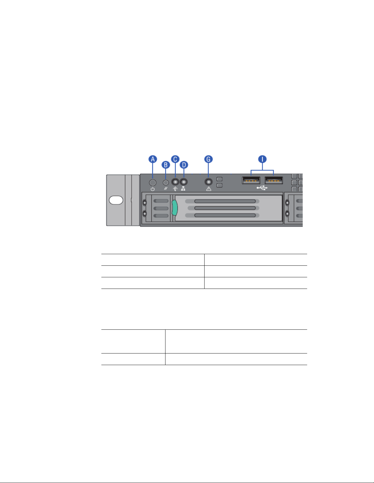
System Front Panel (SR1695GPRX)
The front of the server system includes the following buttons and LEDs.
A. Power/Sleep Button B. System Reset Button
C. Power/Sleep LED D. System NIC 5 Activity LED
G. System Status LED I. USB 2.0 Connectors
Figure 2. Front Controls and LEDs (SR1695GPRX)
Table 2. Front Control Button Function
Power/Sleep Button Toggles the system power on/off. This button also
fun
ctions as a Sleep Button if enabled by an ACPI-
compliant operating system.
System Reset Button Reset system to reboot
4 Intel® Server System SR1695GPRX Service Guide
Page 25
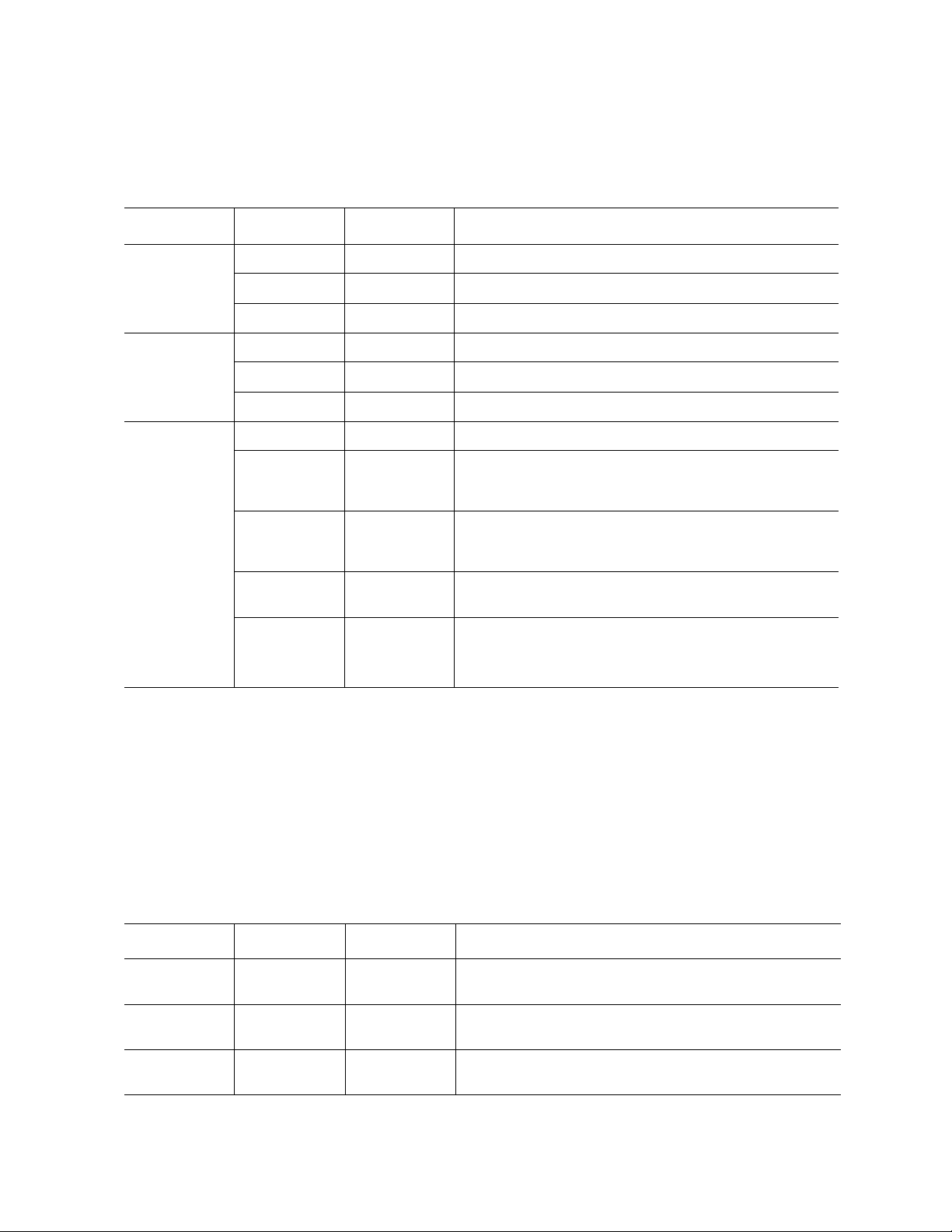
Table 3. Front LED Indicator Functions
LED Color State Description
Power/Sleep Green On Power on/ACPI S0 state.
Green Blink Sleep/ACPI S1 state.
- Off Power Off/ACPI S5 state.
LAN Green On LAN Link no Access.
Green Blink LAN Activity.
- Off No link.
System Status Green On System Ready/No Alarm.
Green Blink System ready, but degraded: redundancy lost such as the
powe
r supply or fan failure; non-critical temp/voltage
threshold; battery failure; or predictive power supply failure.
Amber On Critical Alarm: Critical power modules failure, critical fans
failure
, voltage (power supply), critical temperature and
voltage.
Amber Blink Non-Critical Alarm: Redundant fan failure, redundant power
module
Off Off Power off: System unplugged.
Power on: System powered off and in standby, no prior
deg
NOTES:
1. Blink rate is ~1 Hz at 50% duty cycle.
2. It is also off
3. The power LED sleep indication is maintained on standby by the chipset. If the system is
powered down without going through the BIOS, the LED state in effect at the time of power off
is restored when the system is powered on until the BIOS clear it.
4. If the system is not powered down normally, it is possible the Po wer LED will b link at the same
time the system status LED is off due to a failure or configuration change that prevents the
BIOS from running.
when the system is powered off (S5) or in a sleep state (S1).
failure, non-critical temperature and voltage.
raded\non-critical\critical state.
Table 4. SSI Power LED Operation
State Power Mode LED Description
Power of f Non-ACPI Off System power is off and the BIOS has not initialized the
chipset.
Power on Non-ACPI Solid on System power is on but the BIOS has not yet initialized the
chipset.
S1 Sleep ACPI Blink DC power is still on. The operating system has saved
conte
xt and gone into a level of low-power state.
Intel® Server System SR1695GPRX Service Guide 5
Page 26

State Power Mode LED Description
S0 ACPI Solid on System and the operating system are up and running.
NOTE: Blink ra
te is ~ 1Hz at 50% duty cycle.
Table 5. System Status LED Operation
LED Color State Description
Off N/A Not ready Power off or BMC initialization completes if no degraded,
Green/Amber Both solid on Not ready Pre DC Power On – 15-20 second BMC Initialization when
Green Solid on Ok System ready.
Blink Degraded BIOS detected:
non-critical
, critical, or non-recoverable conditions exist
after power cable plug in.
AC i
s applied to the server. The system will not POST until
BMC initialization completes.
1. Unable to use all of the installed memory (more than
one DIMM installed).
1
2. In a mirrored configuration, when memory mirroring
takes place and system loses memory redundancy.
This is not covered by (2).
1
3. PCI Express* correctable link errors.
Integrated BMC detected
1. Redundancy loss such as a power supply or fan.
Applies only if the associated platf
orm subsystem
has redundancy capabilities.
2. CPU disabled – if there are two CPUs and one CPU
is disabled.
3. Fan alarm – Fan failure. Number of operational fans
should be more than minimum number needed to
cool the system.
4. Non-critical threshold crossed – Temperature,
voltage, power nozzle, power gauge, and
PROCHOT2 (Therm Ctrl) sensors.
5. Battery failure.
6. Predictive failure when the system has redundant
power supplies.
6 Intel® Server System SR1695GPRX Service Guide
Page 27

LED Color State Description
Amber Blink Non-critical Non-fatal alarm – system is likely to fail.
BIOS detected:
1. In non-mirroring mode, if the threshold of ten
correctable errors is crossed within the window.
2. PCI Express* uncorrectable link errors.
Integrated BMC Detected
1. Critical threshold crossed – Voltage, temperature,
2. VRD Hot asserted.
3. Minimum number of fans to cool the system are not
r nozzle, power gauge, and PROCHOT (Therm
powe
Ctrl) sensors.
present or have failed.
1
Solid on Critical, non-
recove
rable
Fatal alarm – system has failed or shutdown.
BIOS detected:
1. DIMM failure when there is one DIMM present and
2. Run-time memory uncorrectable error in non-
3. CPU configuration error (for instance, processor
Integrated BMC Detected
1. CPU CATERR signal asserted.
2.
3. CPU THERMTRIP.
4. No power good – power fault.
– Power Unit Redundancy sensor – Insufficient
NOTES:
1. The BIOS detects these conditions and sends a Set Fault Indication command to the
Integrated BM
2. Blink rate is ~ 1Hz at 50% duty cycle.
C to provide the contribution to the system status LED.
System Status LED – BMC Initialization
no good memo
redundant mode.
stepping mismatch).
CPU 1 i
resources offset (indicates not enough power
supplies are present).
ry is present.
1
s missing
1
When power is first applied to the system and 5V -STBY is present, the BMC controller on
the server board requires 15-20 seconds to initialize. During this time, the system status
LED will be solid on, both amber and green. Once BMC initialization has completed, the
status LED will stay green solid on. If power button is pressed before BMC initialization
completes, the system will not boot to POST.
Intel® Server System SR1695GPRX Service Guide 7
Page 28
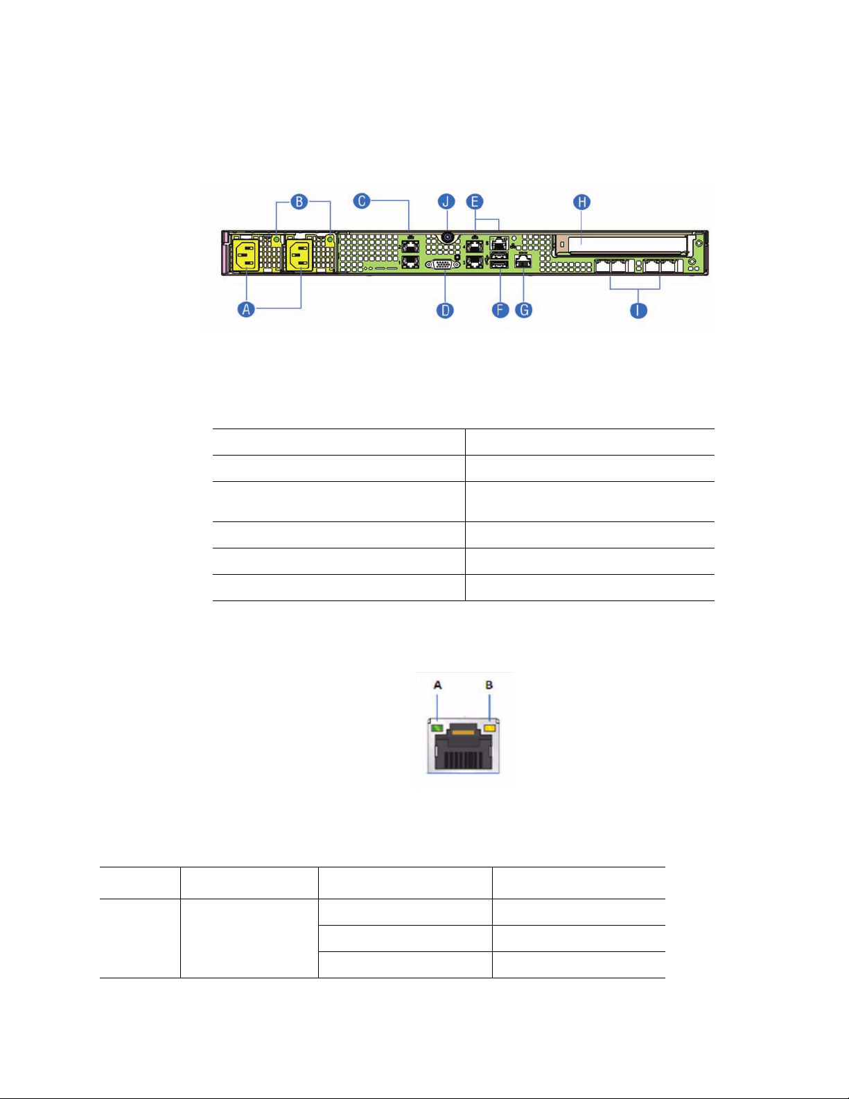
System Rear
A. Redundant Power Supply Units G. RJ-45 Serial Port
Figure 3. Back Panel Connectors
B. Power Supply Status LED H. PCI Express* Add-in slot
C. NIC 1 & 2 connectors RJ-45 I. Reserved for IO module external
connectors
D. Video Out J. Top cover lock screw
E. NIC 3, 4 & 5 connectors RJ-45
F. Dual USB Ports
The NIC LEDs on the NIC connector are marked as A and Bas shown below.
The following table provides the
LED information.
Table 6. NIC LED Descriptions
LED LED State LED State NIC State
A Green Off LAN link is not established.
On LAN link is established.
Blinking LAN activity is occurring.
8 Intel® Server System SR1695GPRX Service Guide
Page 29
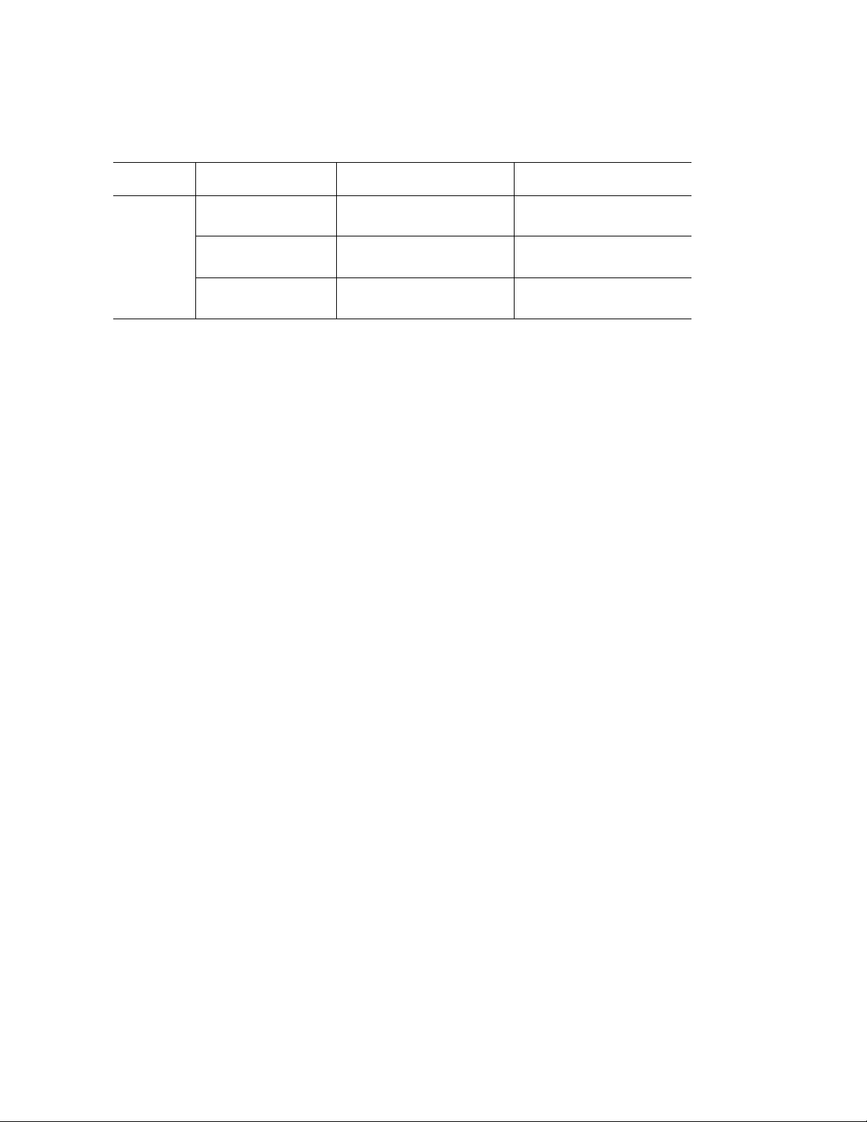
Table 6. NIC LED Descriptions
LED LED State LED State NIC State
B N/A Off 10 Mbit / sec data rate is
selected
Green On 100 Mbit / sec data is
selected
Yellow On 1000 Mbit / sec data rate is
selected
Intel® Server System SR1695GPRX Service Guide 9
Page 30

Peripheral Devices (SR1695GPRX)
The server system provides locations and hardware for installing hard drives, slimline
CD-ROM drive, or DVD-ROM drive. You must purchase the drives separately. Available
options include:
• Slimline Optical Drive Bay
• Four Hard Disk Drive Bays
Hard Disk Drives
The Intel® Server System SR1695GPRX ships with four hot-swap drive carriers for
installing four SATA/SAS hard disk drives, either 3.5-inch or 2.5-inch HDDs.
For instructions on installing hard drives, see “Installing and Removing a Hot-swap Hard
Drive”.
Note: Each drive can consume up to 17 W
maximum ambient temperature of 45
®
Note: The Intel
drives. See “Server System References” for an Internet link to a list of supp
hardware.
Server System SR1695GPRX does not support all Serial ATA (SATA) hard
of power. Drives must be specified to run at a
° C.
orted
10 Intel® Server System SR1695GPRX Service Guide
Page 31

Slimline Optical Drive Carrier
One slimline optical drive latch is included with your server system. You mush purchase
the optical drive separately . You can only insert or remove the slimline optical drive when
the system power is turned off. Drive in the optical drive bay is NOT hot-swappable.
To use one of the drives provided by Intel, use the
• SATA slimline DVD drive: AXXSATADVDROM
• SATA slimline DVD rewritable drive: AXXSATADVDRWROM
Note: The Intel
to the table in Preface for an Internet link to a list of supported hardware. Intel provides
accessory kits for these drives.
For installation instructions for an optical drive, see “Installing or Removing a Slimline
Optical Drive (SR1695GPRX)”.
following order codes:
®
Server System SR1695GPRX does not support all slimline optical drives. Refer
Intel® Server System SR1695GPRX Service Guide 11
Page 32

EP0003
A
B
C
D
E
G
H
I
J
F
K
Internal Components (SR1695GPRX)
A. Server Board G. System Blowers (2)
B. Power Supply H. Front Panel
C. Hard Drive Bays I. Rotor Fan
D. Slimline Optical Drive Bay J. PCIe* Riser Assembly
E. BBU Support K. Rack Handles
F. Processor Air Duct
Figure 4. System Components (SR1695GPRX)
12 Intel® Server System SR1695GPRX Service Guide
Page 33

Server Board Connectors/Components
Intel® Server System SR1695GPRX Service Guide 13
Page 34

A. Dual Intel® I/O Expansion
Module Connectors
B. PCI Express x16 Gen2 U. PCH Chipset
C. CMOS Battery V. SAS Module Connector
D. RJ-45 Serial port Connector W. System FAN 1
E. RJ-45 GbE(NIC5) and Dual
USB combo connector
F. Dual port RJ-45 GbE LAN
Connector (NIC3 and NIC4)
G. SATA RAID key Z. HSBP Connector
H. DB15 Video port AA. USB Floppy
I. Dual port RJ-45 GbE LAN
Conn
ector (NIC1
J. Diagnostic/ID/Status LED CC. SATA 3
K. Main Power Connector DD. SATA 1
L. System FAN 4 EE. SATA 4
M. CPU Power Connector FF. SATA 2
N. CPU Fan GG. SATA 5
and NIC2)
T. USB SSD Connector
X. IPMB Connector
Y. SATA SGPIO Connector
BB. SATA 0
O. Power Supply AUX Connector HH. Internal USB connector
P. DIMM Slots II. Intel
Q. System FAN 3 JJ. Front Panel Connector
R. System FAN 2 KK. Internal Serial Port B
S. CPU Socket
®
RMM3 Lite
Figure 5. S3420GPRX Connector and Component Locations
14 Intel® Server System SR1695GPRX Service Guide
Page 35

ME Force
Update
J1F1
Disable
Enable
BIOS
Recovery
J1F3
Disable
Enable
BIOS
Recovery
J1F3
Disable
Enable
Password
Clear
J1F2
Protect
Clear
CMOS
Clear
J1F5
Disable
Enable
Password
Clear
J1F2
Protect
Clear
CMOS
Clear
J1F5
Disable
Enable
CMOS
Clear
J1F5
Disable
Enable
BMC Force
Update
J1E1
Disable
Enable
Chassis Intrusion
Header
J1D1
Configuration Jumpers
Rack and Cabinet Mounting Options
Figure 6. Configuration Jumper Descriptions
The chassis was designed to support 19 inches wide by up to 30 inches deep server
cabinets. The system supports the following Intel rack mount options:
• A basic slide rail kit (Product order code – AXXBASICRAIL) is designed to mount
the chassis into a standard (19 inches by up to 30 inches deep) EIA-310D
compatible server cabinet.
• A tool-less slide rail kit (Product order code – AXXHERAIL2) is designed to mount
the chassis into a standard (19 inches by up to 30 inches deep) EIA-310D
Intel® Server System SR1695GPRX Service Guide 15
compatible server cabinet.
• A chassis cable management arm (Product order code – AXXRACKARM2), which
is compliant with AXXHERAIL2, is also available.
Page 36

Hardware Requirements
To avoid integration difficulties and possible board damage, your system must meet the
following requirements outlined. For a list of qualified components, see the links under
“Server System References”.
Processor
The Intel® Server Board S3420GPRX supports one Intel® Xeon® 3400 processor series
with 95 W Thermal Design Power (TDP).
®
Intel
Server Board S3420GPRX can also support Intel® CoreTM i3 processor.
For a complete list of supported processors, see the links under “Server System
References”.
Memory
The Intel® Server Board S3420GPRX supports a DDR3-based memory sub-system. The
server board supports up to three DIMM sockets per channel.
Refer to the following table for c
hannel slot configuration. The minimal memory
population is one DIMM in memory slot DIMM_A1. For a complete list of supported
memory DIMMs, see the links under “Server System References”.
Table 7. Channel Slot Configuration
Channel A Channel B
A1 A2 A3 B1 B2
RDIMM X
X X
X X X
X X
X X X
X X X X
B
3
X X X X
X X X X X
X X X X X X
16 Intel® Server System SR1695GPRX Service Guide
Page 37

Table 7. Channel Slot Configuration
Channel A Channel B
A1 A2 A3 B1 B2
UDIMM X
X X
X X
X X X
X X X X X
The Independent Channel Mode is the default Maximum Performance Mode preferred for
®
Xeon® processor 3400 based platforms. All three channels may be populated in any
Intel
B
3
order and have no matching requirements. All channels must run at the same interface
frequency, but individual channels may run at different DIMM timings (RAS latency,
CAS latency, etc.).
The Intel
®
SAS Entry RAID Module option is enabled by default once the Intel® SAS
Entry RAID Module.
Intel® Server System SR1695GPRX Service Guide 17
Page 38

18 Intel® Server System SR1695GPRX Service Guide
Page 39

2 Server Utilities
Using the BIOS Setup Utility
This section describes the BIOS Setup Utility options, which are used to change server
configuration defaults. You can run BIOS Setup with or without an operating system
present. See the links under “Server System References” for a link to the Intel
Board S3420GPRX Technical Product Specification where you
specific BIOS setup screens.
Starting Setup
You can enter and start BIOS Setup under several conditions:
®
Server
will find details about
• When you turn on the server, after POST completes the memory test.
• When you have moved the CMOS jumper on the server board to the “Clear CMOS”
position (enabled).
In the two conditions listed previously, during the Power On S
see this prompt:
Press <F2> to enter SETUP
In a third condition, when CMOS/NVRAM is corrupted, you will see other prompts but
not the <F2> prompt:
Warning: CMOS checksum invalid
Warning: CMOS time and date not set
In this condition, the BIOS loads the default values for CMOS and attempts to boot.
If You Cannot Access Setup
If you cannot access the BIOS Setup, you might need to clear the CMOS memory. For
instructions on clearing the CMOS, see “Clearing the CMOS”.
Setup Menus
elf Test (POST), you will
Each BIOS Setup menu page contains a number of features. Except for those features that
are provided only to display automatically configured information, each feature is
associated with a value field that contains user-selectable parameters. A user can change
these parameters if they have adequate security rights. If a value cannot be changed for
any reason, the feature's value field is inaccessible.
Intel® Server System SR1695GPRX Service Guide 19
Page 40

“Setup Menu Key Use” describes the keyboard commands you can use in the BIOS Setup
menus.
Table 8. Setup Menu Key Use
Key to Press Description
<F1> Pressing the <F1> key on any menu opens the general help window.
Left and right arrows The left and right arrow keys are used to move between the major menu
p
. The keys have no effect if a submenu or pick list is displayed.
ages
Up arrow Select Item up - The up arrow is used to select the previous value in a
menu item's option list, or a value field pick list. Pressing <Enter>
activates the selected item.
Down arrow Select Item down - The down arrow is used to select the next value in a
menu item's o
activates the selected item.
<F5> or <-> Chang e Value - The minus key or the <F5> function key is used to
change
scrolls through the values in the associated pick list without displaying
the full list.
ption list, or a value field pick list. Pressing <Enter>
the value of the current item to the previous value. This key
<F6> or <+> Change Value - The plus key or the <F6> function key is used to change
the
lue of the current menu item to the next value. This key scrolls
va
through the values in the associated pick list without displaying the full
list. On 106-key Japanese keyboards, the plus key has a different scan
code than the plus key on the other keyboard, but it has the same effect.
<Enter> Execute Command - The <Enter> key is used to activate submen
when the selected feature is a submenu, or to display a pick list if a
selected feature ha s a v alue field, o r to select a sub-f ield f or mu lti-v alued
features like time and date. If a pick list is displayed, pressing <Enter>
will undo the pick list, and allow another selection in the parent menu.
<Esc> Exit - The <Esc> key provides a mechanism for backing out of any field.
<F9> Setup Defaults - Pressing <F9> causes the following to display:
This k
ey will undo the pressing of the <Enter> key. When <Esc> is
pressed while editing any field or selecting features of a menu, the
parent menu is re-entered. When <Esc> is pressed in any submenu, the
parent menu is re-entered. When <Esc> is pressed in any major menu,
the exit confirmation window displays and the user is asked whether they
want to discard their changes.
Setup Confirmation
Load default configu
[Yes] [No]
If “Yes” is selected and <Enter> is presse
their default values. If “No” is selected and <Enter> is pressed, or <Esc>
is pressed, the user is returned to where they were before <F9> was
pressed without affecting any existing field values.
ration now?
d, all Setup fields are set to
us
20 Intel® Server System SR1695GPRX Service Guide
Page 41

Key to Press Description
<F10> Save and Exit - Pressing <F10> causes the following message to
display:
If “Yes” is selected and <Enter> is pressed, all changes are saved and
Setup is exi
pressed, the user is returned to where they were before <F10> was
pressed without affecting any existing values.
Upgrading the BIOS
The upgrade utility allows you to upgrade the BIOS in flash memory. The code and data in
the upgrade file include the following:
Table 8. Setup Menu Key Use
Setup Confirmation
Sav
e Config
ted. If “No” is selected and <Enter> is pressed, or <Esc> is
uration changes and exit now?
[Yes] [No]
• On-board system BIOS, including the recovery code, BIOS Setup Utility, and
strings.
• On-board video BIOS, and other option ROMs for devices embedded on the server
board.
• OEM binary area
• Microcode
Preparing for the Upgrade
The following steps explain how to prepare to upgrade the BIOS, including how to record
the current BIOS settings and obtain the upgrade utility.
Note: In the unlik
need to follow a recovery process to return the system to service. See “Server System
References” for a link to necessary software and instructions.
Recording the Current BIOS Settings
1. Boot the computer and press <F2> when you see the following message:
Press <F2> Key if you want to run SETUP
2. Write down the current settings in the BIOS Setup program.
ely event that a BIOS error occurs during the BIOS update process, you may
Note: Do not skip Step 2. You need these settings to configure
your server at the end of the
procedure.
Intel® Server System SR1695GPRX Service Guide 21
Page 42

Obtaining the Upgrade
Download the BIOS image file to a temporary folder on your hard drive. See “Server
System References” for a link to the update software.
Note: Before
the readme file distributed with the BIOS image file. The release notes contain critical
information regarding jumper settings, specific fixes, and other information to complete
the upgrade.
attempting a BIOS upgrade, review the instructions and release notes provided in
Upgrading the BIOS
Follow the instructions in the readme file that came with the BIOS upgrade. When the
update completes, remove the bootable media from which you performed the upgrade.
Caution: Do not power down the system duri
Note: You may encounter a CMOS Ch
happens, shut down the system and boot it again. CMOS checksum err ors r equir e that you
enter Setup, check your settings, save your settings, and exit Setup.
Recovering the BIOS
If an update to the system BIOS is not successful or if the system fails to complete POST
and the BIOS is unable to boot an operating system, it may be necessary to run the BIOS
recovery procedure.
ng the BIOS update process!
ecksum error or other problem after reboot. If this
To place the baseboard into recovery mode, move the boot option jumper (loca
baseboard) to the recovery position. The BIOS can then execute the recovery BIOS (also
known as the boot block) instead of the normal BIOS. The recovery BIOS is a selfcontained image that exists solely as a fail-safe mechanism for installing a new BIOS
image.
Note: During the recovery mode, video is not
start of the recovery process. The entire process takes two to four minutes. A successful
update ends with two high-pitched beeps. Failure is indicated by a long series of short
beeps.
initialized. One high-pitched beep announces the
ted on the
Recovering the BIOS
The following steps boot the recovery BIOS and flashes the normal BIOS:
1. Power down and unplug the system from the AC power source.
2. Move the recovery jumper at JIF3 from the spare
pins 1 and 2. Refer to the following figure.
22 Intel® Server System SR1695GPRX Service Guide
location at pins 2 and 3 to cover
Page 43

BIOS
Recovery
J1F3
Default
2
Recover
3
AF003180
Figure 7. BIOS Recovery Jumper
3. Insert the bootable BIOS Recovery media con
taining the new BIOS image files. A
BIOS recovery can be accomplished from SATA CD and USB Mass Storage
device. Please note this platform does not support recovery from a USB floppy . The
recovery media must contain the following files under the root directory:
• FVMAIN.FV
• UEFI iFlash32
• *Rec.CAP
• Startup.nsh (update accordingly to use proper *Rec.CAP file)
4. Plug the system into the AC power source and power it on.
5. The BIOS POST screen will appear displaying the progress, and the system will
automatically boot to the EFI SHELL.
6. Remove the recovery media.
7. Power down and unplug the system from the AC power source.
8. Move the BIOS recovery jumper at J1F3 back to the original position, covering
storage pins 1 and 2.
9. Plug the system into the AC power source and power it up to confirm the recovery
was successful.
10. Do NOT interrupt the BIOS POST during the first boot.
Clearing the Password
If the user or administrator password(s) is lost or forgotten, moving the password clear
jumper into the “clear” position clears both passwords. Before a new password(s) is set,
you must restore the password clear jumper to its original position.
1. Power down the system and disconnect the AC power.
Intel® Server System SR1695GPRX Service Guide 23
Page 44

2. Open the server chassis.
3. Move the jumper from the normal operation position, Password Clear Protect, at
pins 1 and 2 to the Password Clear Erase position, covering pins 2 and 3 as
indicated in the following diagram.
4. Reconnect the AC power, power up the system.
Power down the system
5.
6. Return the Password Clear jumper to the Password Clear Protect position, covering
pins 1 and 2.
7. Reconnect the AC power and power up the server.
8. Close the server chassis. The password is cleared and can be reset by going into the
BIOS setup.
Clearing the CMOS
Password
Clear
J1F2
Default
2
Passwo rd
Clear
3
Figure 8. Password Recovery Jumper
and disconnect the AC power.
AF003181
If you cannot access the BIOS setup screens, you must use the CMOS Clear jumper to
reset the configuration RAM.
1. Power down the system and disconnect the AC power.
2. Open the server chassis. For instructions, see your server chassis documentation.
3. Move the jumper from the default operating position (covering pins 1 and 2) to the
reset / clear position (covering pins 2 and 3).
24 Intel® Server System SR1695GPRX Service Guide
Page 45

3
2
Default
CLEAR
CMOS
J1F5
CMOS
Clear
AF003182
3
2
Default
Enabled
J1E1
BMC
Force
Update
AF003394
Figure 9. CMOS Recovery Jumper
4. Wait five seconds.
5. Move th
e jumper back to default position, covering pins 1 and 2.
6. Close the server chassis.
7. Reconnect the AC power and power up the system. The CMOS is cleared and can
be reset by going into the BIOS setup.
Updating the Integrated BMC
Figure 10. BMC Force Update Jumper
When performing the standard Integrated BMC firmware update procedure, the update
utility places the Integrated BMC into an update mode, allowing the firmware to load
safely onto the
flash device. In the unlikely event the Integrated BMC firmware update
process fails (due to the Integrated BMC not being in the proper update state), the server
Intel® Server System SR1695GPRX Service Guide 25
Page 46

board provides an Integrated BMC Force Update jumper, which forces the Integrated
BMC into the proper update state. You should complete the following procedure in the
event the standard Integrated BMC firmware update process fails.
Note: Normal
jumper set to the enabled position. The server should never be run with the Integrated
BMC Force Update jumper set in this position. This jumper setting should only be used
when the standard firmware update process fails. This jumper should remain in the
default / disabled position when the server is running normally.
1. Power down and remove the AC power cord.
2. Open the serve
documentation.
3. Move the jumper from the default operating position (covering pins 1 and 2) to the
enabled position (covering pins 2 and 3).
4. Close the server chassis.
5. Reconnect the AC cord and power up the server.
6. Perform the Integrated BMC firmware update procedure as documented in the
README.TXT file included in the given Integrated BMC firmware update
package. After successful completion of the firmware update process, the firmware
update utility may generate an error stating the Integrated BMC is still in update
mode.
7. Power down and remove the AC power cord.
8. Open the server chassis.
9. Move jumper from the enabled position (covering pins 2 and 3) to the disabled
position (covering pins 1 and 2).
Integrated BMC functionality is
r chassis. For instructions, refer to your server chassis
disabled with the Force Integrated BMC Update
10. Close the server chassis.
11. Reconnect the AC cord and power up the server.
26 Intel® Server System SR1695GPRX Service Guide
Page 47

3 Hardware Installations and
Upgrades
Caution: Except the supported AC 400 W 1+1 hot swap power supply module, no components in the
Note: Most of the illustrations in
®
Server System SR1695GPRX are hot-swappable. Befor e r emovi ng or installing any
Intel
non-hot-swappable component in this server system, you must first take the server out of
service, turn off all peripheral devices connected to the system, turn off the system by
pressing the power button, and unplug the AC power cord from the system or wall outlet.
this chapter show the Intel® Server System SR1695GPRX with
an optional optical drive installed.
Before You Begin
Before working with your server product, pay close attention to the “Safety Information”.
Tools and Supplies Needed
• Phillips* (cross head) screwdriver, #1 bit and #2 bit
• Antistatic wrist strap and conductive foam pad (recommended)
System References
All references to the left, right, front, top, and bottom assume the reader is facing the front
of the server system as it would be positioned for normal operation.
Intel® Server System SR1695GPRX Service Guide 27
Page 48

A
C
B
EP0004
Removing and Installing the Server Cover
Removing the Server System Cover
You must operate the server system with the system cover in place to ensure proper
cooling. You must remove the top cover to add or replace components inside of the server .
Note: Y
None of the internal components a
cover, power down the server and unplug all peripheral devices and the power cable.
ou may need a non-skid surface or a stop behind the server system to prevent the server
sy
stem from sliding on your work surface.
1. Remove the top cover screw (see letter “A”).
2. Loosen the screw at the rear of the chassis (see letter “B”).
3. Push rearward on the blue grip point at the front of the server.
4. Slide the cover back until it stops and then lift the cover upward to remove it. See
letter “C”.
re hot-swappable. Before you remove the server system
Figure 11. Removing the Server System Cover
28 Intel® Server System SR1695GPRX Service Guide
Page 49

Installing the Server System Cover
1. Observe the safety and ESD precautions at the beginning of this book. See “Safety
Information”.
2. Place the cover over the server system so that the side edges of the cover sit just
inside the server system sidewalls. Slide the cover forward (see letter “A” in
Figure 12).
3. Tighten the screw at the rear of the server (see letter “B”) and install the top cover
screw (see letter “C”).
B
A
C
EP0005
Figure 12. Installing the Server System Cover
Removing and Installing the Processor Air Duct
The system requires the use of an air duct to direct airflow and sustain appropriate air
pressure. Always operate your server system with the air duct in place. The air duct is
required for proper airflow within the server system.
Intel® Server System SR1695GPRX Service Guide 29
Page 50

Air Duct
EP0006
Removing the Processor Air Duct
1. Observe the safety and ESD precautions at the beginning of this book. See “Safety
Information”.
2. Power down the server and unplug all peripheral devices and the power cable.
3. Remove the server system cover. For instructions, see “Removing the Server
System Cover”.
4. Lift the processor air duct from its location behind the two system blower fans.
Figure 13. Removing the Processor Air Duct
30 Intel® Server System SR1695GPRX Service Guide
Page 51

Air Duct
EP0007
Installing the Processor Air Duct
1. Observe the safety and ESD precautions at the beginning of this book. See “Safety
Information”.
2. Power down the server and unplug all peripheral devices and the power cable.
3. Remove the server system cover. For instructions, see “Removing the Server
System Cover”.
4. Lower the air duct into place, insert the two hooks at the front of the processor air
duct into the corresponding slots on the bracket behind the two system blower fans.
Use caution not to pinch or disengage cables that may be near or under the air duct.
5. Install the server system cover. For instructions, see “Installing the Server System
Cover”.
Figure 14. Installing the Processor Air Duct
Installing and Removing Memory
Caution: The memory is NOT hot-swappable. Before removing or replacing any memory DIMM,
you must first take the server out of service, turn off all peripheral devices connected to
the system, turn off the system by pressing the power button, and unplug the AC power
cord from the system or wall outlet.
The silkscreen on the board for the DIMMs displays DIMM A1, DIMM A2, DIMM
and DIMM B2 starting from the center of the board. See “Memory” for a discussion of the
memory requirements and op
tested DIMMs.
Intel® Server System SR1695GPRX Service Guide 31
tions. See “Server System References” for a link to the list of
B1,
Page 52

Installing DIMMs
To install DIMMs, follow these steps:
1. Observe the safety and ESD precautions at the beg
Information”.
2. Power down the server and unplug all peripheral devices and the AC power cable.
3. Remove the server system cover. For instructions, see “Removing the Server
System Cover”.
4. Locate the DIMM sockets. See Figure 15.
Figure 15. Installing the Memory
inning of this book. See “Safety
5. Make sure the clips at both ends of the DIMM socket(s) are
open position. See letter “A” in Figure 15.
6. Holding the DIMM by the edges, remove it from its anti-static package.
7. Position the DIMM above the socket. Align the notch on the bottom edge of the
DIMM with the key in the DIMM socket. See letter “B” in Figure 15.
8. Insert the bottom edge of the DIMM into the socket. See letter “C” in Figure 15.
9. When the DIMM is correctly positioned, push down on the top edge of the DIMM
until the retaining clips snap into place.
10. Make sure the clips are firmly in place. See letter “D” in Figure 15.
11. Install the server system cover. For instructions, see “Installing the Server System
Cover”.
Removing DIMMs
To remove a DIMM, follow these steps:
1. Observe the safety and ESD precautions at the beginning of this book. See “Safety
Information”.
pushed outward to the
32 Intel® Server System SR1695GPRX Service Guide
Page 53

2. Power down the server and unplug all peripheral devices and the AC power cable.
3. Remove the server system cover. For instructions, see “Removing the Server
System Cover”.
4. Locate the DIMM sockets. See Figure 15.
5. Gently spread the retaining clips at each end of the socket. The DIMM lifts from
the socket.
6. Holding the DIMM by the edges, lift it from the socket, and store it in an anti-static
package.
7. Install the server system cover. For instructions, see “Installing the Server System
Cover”.
Intel® Server System SR1695GPRX Service Guide 33
Page 54

Replacing the Processor
Note: This manual assumes a processor is already installed and you are referring to these steps
to replace your processor. If you are setting up this system for the first time, see the Quick
Start User’s Guide included in the product box.
Caution: Use only pr
References” for a link to the list of compatible processor(s).
Caution: ESD and
the processor by doing the following: (1) Touch the metal chassis before touching the
processor or server board. Keep part of your body in contact with the metal chassis to
dissipate the static charge while handling the processor. (2) Avoid moving around
unnecessarily.
ocessors validated to work with this server board. See “Server System
handling processors: Reduce the risk of electr ostatic dischar ge (ESD) damage to
Removing the Heat Sink and Processor
1. Observe the safety and ESD precautions at the beginning of this book. See “Safety
Information”.
2. Power down the server and unplug all peripheral devices and the AC power cable.
3. Remove the server system cover. For instructions, see “Removing the Server
System Cover”.
4. For removing the processor air ducts, see “Removing the Processor Air Duct”.
5. Loosen the four captive screws on the corners of the heat sink.
6. Twist the heat sink slightly to break the seal between the heat sink and the
processor.
7. Lift the heat sink from the processor. If it does not pull up easily, twist the heat sink
again. Do not force the heat sink from the processor. Doing so could damage the
processor.
8. Lift the processor lever.
9. Raise the CPU load plate.
10. Remove the processor.
11. If installing a replacement processor, see “Installing the Processor”. Otherwise,
install the protective socket cover over the empty processor socket and then
reinstall the chassis cover.
34 Intel® Server System SR1695GPRX Service Guide
Page 55

REMOVE
AF003186
A
B
Installing the Processor
To install a processor, follow these instructions:
1. Observe the safety and ESD precautions at the
beginning of this book. See “Safety
Information”.
2. Power down the server and unplug all peripheral devices and the AC power cable.
3. Remove the server system cover. For instructions, see “Removing the Server
System Cover”.
4. Locate the processor socket and raise the socket handle completely. See Figure 16.
Figure 16. Lifting the Processor Socket Handle
5. Push the rear tab with your finger to slightly lift the front of the load plate. Raise the
load plate completely. Raise the CPU load plate (see Figure 17).
Intel® Server System SR1695GPRX Service Guide 35
Page 56

A
REMOVE
B
REMOVE
Figure 17. Opening the Load Plate
Caution: Do not touch the socket pins; they are very sensitive
6. Remove the processor from the packaging box and remove the protective shipping
cover.
See Figure 18.
A
AF003189
Figure 18. Removing the Shipping Cover
AF003187
and easily damaged.
36 Intel® Server System SR1695GPRX Service Guide
Page 57

AF003190
A
REMOVE
AF003368
7. Orient the processor with the socket so the processor cutouts match the socket
notches. See letter “A” in Figure 19.
8. Set the processor into place as shown by letter “B” in Figure 19.
Figure 19. Installing the Processor
Note: Make sure
the alignment triangle mark and the alignment triangle cutout align correctly.
9. Remove the protective socket cover. See Figure 20.
Figure 20. Rem
oving the Protective Socket Cover
Note: Retain the protective socket cover for use w
replaced.
hen removing a processor that will not be
Intel® Server System SR1695GPRX Service Guide 37
Page 58

Processor
Socket
Chassis
Front
AIRFLOW
AF003369
10. Lower the CPU load plate.
11. Lower the socket lever.
12. Install the heat sink. For instructions, see “Installing the Heat Sink”.
Installing the Heat Sink
Before installing the heat sink, you must install your processor. For instructions, see
“Installing the Processor”.
Caution: The heat sink has Ther
caution when you unpack the heat sink so you do not damage the TIM.
1. Remove the protective cover from the TIM on the underside of the heat sink. Do
not touch the TIM.
2. Orient the heat sink over the processor as shown in Figure 21. Yo u must position
the fins as shown to provide correct airflow through the system.
3. Set the heat sink over the processor, lining up the four captive screws with the four
posts surrounding the processor.
4. Loosely screw in the captive screws on the heat sink corners in a diagonal manner
as shown by the four circled numbers in Figure 21. Do not fully tighten one screw
before tightening another.
5. Gradually and equally tighten each captive screw in the same order until each is
firmly tightened.
mal Interface Material (TIM) located on the bottom of it. Use
Figure 21. Installing the Heat Sink
38 Intel® Server System SR1695GPRX Service Guide
Page 59

AF003302
A
B
6. Reinstall and reconnect any parts you removed or disconnected to reach the
processor sockets.
7. Install the server system cover. For instructions, see “Installing the Server System
Cover”.
Installing and Removing a Hot-swap Hard Drive
You can install up to two fixed SATA drives in the Intel® Server System SR1695GPRX.
See “Server System References” for a link to a list of supported hardware.
Caution: If you install les
carriers with drive blanks to maintain proper system cooling.
To avoid possible damage to your server system, use only the driv
with your system.
s than four drives or devices, the empty drive bays must be occupied by
e carriers that came
Installing a SAS or SATA Hot-swap Hard Disk Drive
Note: The server system does not support all hard drives. See “Server System References” for a
link to a list of supported hardware.
1. Open the latch at the front of the hard drive carrier (see letter “A”).
2. Pull out on the black lever and slide the carrier from the server system (see letter
“B”).
Figure 22. Pulling out the back lever
3. Remove the hard drive from its wrapper and place it on an antistatic surface.
Intel® Server System SR1695GPRX Service Guide 39
4. Set any jumpers and/or switches on the drive according to the drive manufacturer's
instructions.
Page 60

AF003303
B
A
5. With the drive circuit-side down, position the connector end of the drive so that it is
facing the rear of the drive carrier.
6. Align the holes in the drive to the holes in the drive carrier and attach it to the
carrier with the screws that were attached to the drive blank.
Figure 23. 2.5 HDD Installation
40 Intel® Server System SR1695GPRX Service Guide
Page 61

AF003304
B
A
AF003305
B
A
Figure 24. 3.5 HDD Installation
7. With the black lever in the fully open position, slide the drive assembly into the
server system. The green latch at the front of the drive carrier must be to the right.
Do not push on the black drive carrier lever until the lever begins to close by itself.
8. When the black drive carrier lever begins to close by itself, push on it to lock the
drive assembly into place.
Figure 25. Locking the drive assembly
Intel® Server System SR1695GPRX Service Guide 41
Page 62

Removing a SAS or SATA Hot-swap Hard Disk Drive
1. Press in on the green latch at the front of the hard drive carrier. and pull out on the
black lever to slide the carrier from the server system.
2. Remove the four screws that attach the hard drive to the drive carrier . Lift the drive
from the carrier and store the drive in an anti-static bag.
3. With the black lever in the fully open position, slide the drive carrier into the server
system. The green latch must be to the right. Do not push on the black lever until
the lever begins to close by itself.
Note: All hard drive carriers must be installed in the server system and populated
either with a drive or without a drive to maintain system thermals.
4. When the black lever begins to close by itself, push on it to lock the drive carrier
into place.
Installing or Removing a Slimline Optical Drive
(SR1695GPRX)
Caution: Slimline optical drives are NOT hot-swappable. Before removing or replacing the drive,
you must first take the server out of service, turn off all peripheral devices connected to
the system, turn off the system by pressing the power button, and unplug the AC power
cord from the system or wall outlet. To maintain proper system cooling, if you do not
install a device at this location, you must install the provided filler blank.
Installing a Slimline Optical Drive
1. Remove the slimline drive bay filler blank, if installed.
42 Intel® Server System SR1695GPRX Service Guide
Page 63

AF003311
B
A
AF003312
Figure 26. Removing the Knockout in Bezel for Optical Opening
2. Obtain the optical drive, and the optical drive latch from system package.
3. Screw the latch to the optical drive, and plug in the composed SATA/SATA Power
cable, which is shipped in system package.
Figure 27. Attaching the Brackets to the Optical Drive
4. Lead
the SATA/SATA Power cable through the optical drive bay before inserting
the drive.
Intel® Server System SR1695GPRX Service Guide 43
Page 64

B
A
AF003313
EP0009
B
A
5. Slide the optical drive assembly in through the front of the chassis, as shown by
letter “A in the following figure. The assembly will automatically be locked if the
drive assembly is in position.
6. Connect the SATA cable connector to SATA port 4 or 5 on server board.
7. Connect the SATA power connector to P6 connector from system power supply.
Figure 28. Installing the Optical Drive into the Server System
44 Intel® Server System SR1695GPRX Service Guide
Page 65

Installing or Replacing a PCIe* Riser Card
Caution: The PCIe* Riser card is NOT hot-swappable. Before removing or replacing the PCIe*
Riser card, you must first take the server out of service, turn off all peripheral devices
connected to the system, turn off the system by pressing the power button, and unplug the
AC power cord from the system or wall outlet.
You have the option to install one of two PCIe* R
• A low-profile PCI Express* riser with one PCI Express x16 slot.
Note: To eliminate the possibility of installing the replacement connector on the wr
the PCIe* Riser assembly, replace one connector at a time.
Replacing a PCIe* Riser Card
1. Observe the safety and ESD precautions at the beginning of this book. See “Safety
Information”.
2. Power down the server and unplug all peripheral devices and the AC power cable.
3. Remove the server system cover. For instructions, see “Removing the Server
System Cover”.
4. Disconnect any cables attached to any add-in cards.
5. Remove the PCIe* Riser assembly.
6. Remove any add-in cards from the PCIe* Riser connector. For instructions, see
“Removing a PCI Add-in Card”.
7. Remove the screw that attaches the riser card to the riser assembly. Save these
screws to be used later.
iser cards into your server system:
ong side of
Intel® Server System SR1695GPRX Service Guide 45
Page 66

EP0001
Figure 29. Removing Riser Assembly
8. Install the replacement riser card, if desired.
9. Install the PCIe* Riser assembly into the server system.
10. Install the server system cover. For instructions, see “Installing the Server System
Cover”.
11. Plug all peripheral devices and the AC power cable into the server.
Installing a PCIe* Riser Card
1. Observe the safety and ESD precautions at the beginning of this book. See “Safety
Information”.
2. Power down the server and unplug all peripheral devices and the AC power cable.
3. Remove the server system cover. For instructions, see “Removing the Server
System Cover”.
4. Disconnect any cables attached to any add-in cards.
5. Remove the PCIe* Riser assembly.
6. Remove any add-in cards from the PCIe* Riser connector. For instructions, see
“Removing a PCI Add-in Card”.
7. Use the screw to attach the riser card to the riser assembly.
46 Intel® Server System SR1695GPRX Service Guide
Page 67

A
B
EP0002
Figure 30. Installing Riser Assembly
8. Install an PCI add-in card if desired. For instructions, see “Installing a PCI Add-in
Card”.
9.
Install the PCIe* Riser assembly into the server system.
10. Connect any cables to add-in cards that require them. See your add-in card
documentation for information and add-in card requirements.
11. Re-install the processor air duct. For instructions, see “Installing the Processor Air
Duct”.
12. Install the server system cover. For instructions, see “Installing the Server System
Cover”.
13. Plug all peripheral devices and the AC power cable into the server.
Installing and Removing a PCI Add-in Card
Caution: The add-in cards are NOT hot-swappable. Before removing or replacing an add-in card,
you must first take the server out of service, turn off all peripheral devices connected to
the system, turn off the system by pressing the power button, and unplug the AC power
cord from the system or wall outlet.
Installing a PCI Add-in Card
1. Observe the safety and ESD precautions at the beginning of this book. See “Safety
Information”.
Intel® Server System SR1695GPRX Service Guide 47
Page 68

Riser Connector
Riser Card
Add-in Card
AF003371
A
B
C
2. Power down the server and unplug all peripheral devices and the AC power cable.
3. Remove the server system cover. For instructions, see “Removing the Server
System Cover”.
4. Remove the PCIe* Riser assembly. For instructions, see “Replacing a PCIe* Riser
Card”.
5. Remove the screw at the rear of the riser assembly. See letter “A” in Figure 31.
Save this screw. You will reinstall it later.
6. If a filler panel is installed over the opening at the rear of the riser assembly, lift it
from the riser assembly. See letter “B” in Figure 31. Save the filler panel in case
you later need to remove the add-in card.
7. Insert the add-in card into the socket in the riser assembly. Push the add-in card into
place firmly until it seats in the riser card connector, but use caution so you do not
twist or bend the card. See letter “C” in Figure 31.
8. Re-install the screw you removed in Step 5. See letter “A” in Figure 31.
Figure 31. Installing an Add-In Card
9.
Install the
PCIe* Riser assembly into the server system. For instructions, see
“Installing a PCIe* Riser Card”.
10. Install the server system cover. For instructions, see “Installing the Server System
Cover”.
11. Plug all peripheral devices and the AC power cable into the server.
Removing a PCI Add-in Card
1. Observe the safety and ESD precautions at the beginning of this book. See “Safety
Information”.
2. Power down the server and unplug all peripheral devices and the AC power cable.
3. Remove the server system cover. For instructions, see “Removing the Server
System Cover”.
4. Remove the PCIe* Riser assembly. For instructions, see “Replacing a PCIe* Riser
Card”.
5. Remove the screw at the rear of the riser assembly. See letter “A” in Figure 32.
Save this screw. You will use it later.
48 Intel® Server System SR1695GPRX Service Guide
Page 69

Riser Connector
Riser Card
Add-in Card
AF003372
A
C
B
6. Pull the add-in card from the socket in the riser assembly. You may need to wriggle
the card from front to back to remove it, but use caution so you do not twist o r bend
the card. See letter “B” in Figure 32.
7. Install a filler panel over the opening at the rear of the riser assembly. See letter “C”
in Figure 32.
8. Re-install the screw you removed in Step 5. See letter “A” in Figure 32.
Note: Make sur
9. Install the PCIe* Riser assembly into the server system. For instructions, see
“Installing a PCIe* Riser Card”.
10. Install the processor air duct. For instructions, see “Installing the Processor Air
Duct”.
11. Install the server system cover. For instructions, see “Installing the Server System
Cover”.
12. Plug all peripheral devices and the AC power cable into the server.
Figure 32. Removing a Full Height Add-In Card
e
that all empty add-in card slots have filler panels installed.
Intel® Server System SR1695GPRX Service Guide 49
Page 70

EP0011
A
Installing and Removing the I/O Expansion
Module
Installing the I/O Expansion Module
1. Squeeze the sides of the I/O expansion module cover to disengage it from the server
system back panel and remove it (see letter “A”).
Figure 33. Installing the I/O Expansion Module(s)
2. Attach the standoffs to the server board (see letter “A”) and attach the I/O shield
gasket to the module (see letter “B”).
3. Attach the I/O expansion module(s) to the server board (see letter “C”).
50 Intel® Server System SR1695GPRX Service Guide
Page 71

EP0012
B
A
C
Figure 34. Attaching the I/O Expansion Module(s)
Removing the I/O Expansion Module(s)
1. Remove the I/O expansion module(s) from the server board (see letter “A”).
2. Remove the standoffs from the server board (see letter “B”).
3. Install the I/O expansion module cover into the system back panel (see letter “C”).
Intel® Server System SR1695GPRX Service Guide 51
Page 72

RMM3 LITE
Connector
RMM3 LITE
Installing and Removing the RMM3 Lite
Installing the RMM3 Lite
1. Remove the PCI riser assembly. For instructions, see “Replacing a PCIe* Riser
Card”.
2. Position the RMM3 Lite over the server board RMM3 Lite connector (J2D1) as
shown in Figure 35.
Figure 35. Installing the RMM3 Lite to the Server System
3. Install the
“Installing a PCIe* Riser Card”.
PCI riser assembly into the server system. For instructions, see
Removing the RMM3 Lite
1. Remove the PCI riser assembly. For instructions, see “Replacing a PCIe* Riser
Card”.
2. Disconnect the RMM3 Lite from the server board RMM3 Lite connector (J2D1) as
shown in Figure 36.
52 Intel® Server System SR1695GPRX Service Guide
Page 73

RMM3 LITE
RMM3 LITE
Connector
Figure 36. Removing the RMM3 Lite to the Server System
3. Install the PCI riser assembly into the server system. For instructions, see
“Installing a PCIe* Riser Card”.
Replacing the Backplane Board
The instructions below describe how to replace the backplane board in the system.
Removing the Backplane Board
1. Disengage hard drives from the backplane boar d (see letter “A”).
2. Disconnect all cables from the backplane board.
3. Remove two screws on the top of backplane bracket (see letter “B”).
4. Pull out the backplane assembly vertically from the chassis (see letter “C”).
Intel® Server System SR1695GPRX Service Guide 53
Page 74

EP0022
A
B
C
Figure 37. Removing the backplane board
Installing the Backplane Board
1. Lower the backplane assembly into the system (see letter “A”) and fix the
backplane assembly into fix position, aligning with two screw holes on chassis.
2. Tighten two screws to lock the backplane assembly in position (see letter “B”).
3. Connect data/power cables to the backplane connectors.
4. Engage hard drives back to the backplane (see letter “C”).
54 Intel® Server System SR1695GPRX Service Guide
Page 75

EP0015
A
B
C
Figure 38. Installing the backplane board
Intel® Server System SR1695GPRX Service Guide 55
Page 76

A
B
EP0023
Replacing the Server Board
Removing the Server Board
1. Remove the system air duct.
2. If installed, remove the memory, processor heat sinks, and processors from the
server.
3. If installed, remove the PCI riser assembly.
4. If installed, disconnect all SATA cables from the server board.
5. Disconnect the system fans cables from server board.
6. Disconnect all power cables coming from the power supply to the server board.
7. Remove the nine screws from the server board (see letter “A”) and lift the server
board from the server system (see letter “B”).
Figure 39. Removing the Server Board
8. Install the replacement server board. See “Installing the Server Board” on page 57.
56 Intel® Server System SR1695GPRX Service Guide
Page 77

B
A
EP0019
Installing the Server Board
1. Place the server board into the server system as shown in the following figure (see
letter “A”).
2. Attach the server board with nine screws (see letter “B”).
Figure 40. Installing the Server Board
3. Re-con
4. Re-connect the system fan cables to server board.
nect all power cables coming from the power supply to the server board.
5. Re-connect all SATA cables to the server board.
6. Install the PCI riser assembly.
7. Install the memory, processor heat sinks, and processors.
8. Install the system air duct.
Intel® Server System SR1695GPRX Service Guide 57
Page 78

Replacing the CMOS Battery
Caution: The CMOS battery is NOT hot-swappable. Before removing or replacing the CMOS
battery, you must first take the server out of service, turn off all peripheral devices
connected to the system, turn off the system by pressing the power button, and unplug the
AC power cord from the system or wall outlet.
The lithium battery on the server board powers the RTC in the absence of power. When
the battery starts to weaken, it loses voltage, and
in the R TC (for exampl e, the date and time) may be wrong. For a list of approved devices,
contact your customer service representative or dealer.
the server settings stored in CMOS RAM
Warning: Danger
equivalent type recommended by the equipment manufacturer. Discard used batteries
according to manufacturer's instructions.
Advarsel: Lithiumbatteri - Eksplosionsfare ved
batteri af samme fabrikat og type. Levér det brugte batteri tilbage til leverandøren.
Advarsel: Lithiumbatteri - Eksplosjonsfare. Ved utskifting benyttes kun batteri som anbefalt av
apparatfabrikanten. Brukt batteri returneres apparatleverandøren.
Varning: Explosionsfara vid felaktigt batteribyte. Använd samma batterityp eller en ekvivalent typ
som rekommenderas av apparattillverkaren. Kassera använt batteri enligt fabrikantens
instruktion.
Varoitus: Paristo voi räjähtää, jos se on virheellisesti asennettu. Vaihda paristo ainoastaan
laitevalmistajan suosittelemaan tyyppiin. Hävitä käytetty paristo valmistajan ohjeiden
mukaisesti.
of explosion if battery is incorrectly replaced. Replace only with the same or
fejlagtig håndtering. Udskiftning må
1. Observe the safety and ESD precautions at the beginning of this book. See “Safety
Information”.
2. Power down the server and unplug all peripheral devices and the AC power cable.
3. Remove the server system cover. For instructions, see “Removing the Server
System Cover”.
kun ske med
4. Remove the server's cover and locate the battery. See Figure 41.
5. Pull back gently on the metal tab at the top of the battery.
6. Remove the battery from its socket.
58 Intel® Server System SR1695GPRX Service Guide
Page 79

AF003375
Figure 41. Replacing the CMOS Battery
7. Dispose of the battery according to local ordinance.
8. Remove the new lithium battery from its package, and, being careful to observe the
correct polarity, insert it in the battery socket.
9. Close the chassis.
10. Run the BIOS Setup utility to restore the configuration settings.
Intel® Server System SR1695GPRX Service Guide 59
Page 80

Replacing the Power Supply (SR1695GPRX)
Removing the Power Supply
You can replace the power supply if it fails or if one of the fans integrated into it fails. To
replace the power supply, use the following instructions.
1. Disconnect the power cord (see letter “A”).
2. Hold the handle and press the l
B
atch (see letter “B”).
A
C
EP0030
Figure 42. Removing the Power Supply from the Server System
3. Pull the handle to pull out the power supply module (see letter “C”).
60 Intel® Server System SR1695GPRX Service Guide
Page 81

EP0029
A
B
Installing the Power Supply
1. Insert the replacement power supply module into the power supply cage and push
hard until it clicks into place (see letter “A”).
2. Connect the power cord (see letter “B”).
Figure 43. Installing the Power Supply into the Server System.
Intel® Server System SR1695GPRX Service Guide 61
Page 82

Replacing a System Fan (SR1695GPRX)
Caution: The fans are NOT hot-swappable. Before removing or replacing a fan, you must first take
the server out of service, turn off all peripheral devices connected to the system, turn off
the system by pressing the power button, and unplug the AC power cord from the system
or wall outlet.
Note: You cannot replace the fans into the power supp
power supply fails, you must replace the power supply.
If one of the blower fans fails, you can individually replac
supply fails, you must replace the power supply. Use the following steps to replace a
system blower fan or the PCI cooling fan.
ly separately. If one of the fans in the
e them. If a fan in the power
Replacing the System Blower Fans (SR1695GPRX)
1. Observe the safety and ESD precautions at the beginning of this book. See “Safety
Information”.
2. Power down the server and unplug all peripheral devices and the AC power cable.
3. Remove the server system cover. For instructions, see “Removing the Server
System Cover”.
4. Remove the processor air duct (see letter “A” in the figure below). For instructions,
see “Removing the Processor Air Duct”.
5. Remove the two screws that hold the fan in place. Save these screws. You will re-
install them later.
6. Disconnect the fan cable from the server board (see letter “B” in Figure 44).
62 Intel® Server System SR1695GPRX Service Guide
Page 83

EP0017
tcuD riA
7. Lift the fan from the system (see letter “C” in Figure 44).
Figure 44. Removing Fan from the Server System (SR1695GPRX)
8. Install the replacement fan into the chassis (see letter “A” in Figure 45), using the
two screws you removed previously.
9. Connect the fan cable to the server board (see letter “B” in Figure 45).
10. Install the processor air duct (see letter “C” in Figure 45).
Intel® Server System SR1695GPRX Service Guide 63
Page 84

EP0013
tcuD riA
Figure 45. Installing Fan into the Server System (SR1695GPRX)
11. Install the server system cover
Cover”.
12. Plug all peripheral devices and the AC power cable into the server.
Replacing the Rotor Fan
1. Observe the safety and ESD precautions at the beginning of this book. See “Safety
Information”.
2. Power down the server and unplug all peripheral devices and the AC power cable.
3. Remove the server system cover. For instructions, see “Removing the Server
System Cover”.
4. Disconnect the fan cable from the server board.
5. Lift the rotor vertically.
6. With a new rotor, set it on the chassi s. Make sure all four holes in the fan match the
four stubs of the chassis.
7. Connect the fan cable to server board.
. For instructions, see “Installing the Server System
64 Intel® Server System SR1695GPRX Service Guide
Page 85

EP0018
EP0026
Figure 46. Replacing the Rotor Fan
Intel® Server System SR1695GPRX Service Guide 65
Page 86

AF003326
AF003327
Installing and Removing the Rack Handle
Installing the Rack Handle
1. Align the rack handle with the holes on the side of the server system and attach the
rack handle with the three screws.
Figure 47. Installing the Rack Handle
2. Repea
t step 1 on the opposite side of the server.
Removing the Rack Handle
1. Remove the three screws holding the rack handle in place, and remove the rack
handle from the server system.
Figure 48. Removing the Rack Handle
66 Intel® Server System SR1695GPRX Service Guide
Page 87

A
B
AF003544
Removing and Installing the Front Bezel
The front bezel is available as an optional accessory for the Intel® Server System
SR1695GPRX.
Removing the Front Bezel
1. Unlock the bezel with the key and pull the bezel from the server system.
Willow
Brook
Optical
Device
AF003541
Intel® Server System SR1695GPRX Service Guide 67
Figure 49. Removing the Front Bezel
Page 88

Willow
Brook
Optical
Device
AF003542
Installing the Front Bezel
1. At each end of the bezel, line up the center notch on the bezel with the center guide
on the rack handles and push the bezel onto the front of the server system until it
clicks into place. Then lock the bezel with the key.
A
B
AF003543
Figure 50. Installing the Front Bezel
68 Intel® Server System SR1695GPRX Service Guide
Page 89

Appendix A: Technical Reference
Cable Routing
When you add or remove components from your server system, make sure your cables are
routed correctly before reinstalling the server system cover. Use caution to make sure no
cables or wires are pinched and that the airflow from the fans is not blocked. Use the
following figures to determine the correct cable routing.
For readability, separate figures for power cable routin
included. Make sure all necessary power and data cables are connected and routed as
shown. Dashed lines in the drawings indicate a location where a cable is routed beneath a
component and each connector end is labeled with the same letter. For example, the PCI
cooling fan cable is labeled with the letter “C” both where it connects to the server board
and at the PCI cooling fan itself.
g and data cable routing are
Intel® Server System SR1695GPRX Service Guide 69
Page 90

Cable Routing (SR1695GPRX)
RAID Card
Server
Board
Power
Supply
Backup
Unit
Battery
Front Panel
IPMB
SGPIO
SES
BBU
Front Panel USB
Backplane
Optical
Drive
HDD2
Backplane
HDD 0
HDD 1
Figure 51. Cable Routing (SR1695GPRX)
HDD3
EP0020
70 Intel® Server System SR1695GPRX Service Guide
Page 91

400-W Single Power Supply Input Voltages
• 100 - 127V at 47/63 Hz 6.0A
• 200 - 240 V at 47 63 Hz 3.0A
400-W Single Power Supply Output Voltages
Table 9 lists the total wattage available from the power subsystem for each voltage. For
information about calculating the power usage for yo
Power Budget Tool.
Table 9. Power Supply Output Capability
Voltage Maximum Current
+3.3 V 12 A
ur configuration, see SR1695GPRX
+5 V 10 A
+5 V Standby 3 A
+12 V 30 A
Intel® Server System SR1695GPRX Service Guide 71
Page 92

System Environmental Specifications
Table 10. System Office Environmental Summary
Parameter Limits
Operating Temperature +10°C to +35°C with the maximum rate of change not to exceed 10°C per hour.
Non-Operating Temperature -40°C to +70°C
Non-Operating Humidity 50%- 90%, non-condensing with a maximum wet bulb of 28°C
Acoustic noise Sound Pressure: 55 dBA (Rackmount) in an idle state at typical office ambient
temperature. (23°C +/- 2°C) Sound Power: 7. 0 BA in an idle state at typical office
ambient temperature. (23 +/- 2 degrees C)
Shock, operating Half sine, 2 g peak, 11 mSec
Shock, unpackaged Trapezoidal, 25 g, velocity change 136 inches/sec (?40 lbs to > 80 lbs)
Shock, packaged Non-palletized free fall in height 24 inches (?40 lbs to > 80 lbs)
Vibration, unpackaged 5 Hz to 500 Hz, 2.20 g RMS random
Shock, operating Half sine, 2 g peak, 11 mSec
ESD +/-15kV except I/O port +/-8KV per Intel
System Cooling
Requirement in BTU/Hr
EMI operating Required to meet EMI emission requirements, tested as part of system
2050 BTU/hour
®
Environmental test specification
72 Intel® Server System SR1695GPRX Service Guide
Page 93

Appendix B: Troubleshooting
This chapter helps you identify and solve problems that might occur while you are using
the system.
For any issue, first ensure you are using the latest firmware and files. Firmware upgrades
include
controller (HSC). See “Server System References” for a link to the software updates. In
addition to the server firmware and files, also update any driv
installed in your system, such as video drivers, network drivers, and SATA drivers.
updates for the BIOS, Baseboard Management Controller (BMC), and hot-swap
ers used for components you
Intel provides a package called the “Platform Confidence T
diagnostics. See “Server System References” for a link to this software.
If you cannot resolve your server problems on your own, see “Getti ng Help” for
assistance.
Resetting the System
Before going through in-depth troubleshooting, attempt first to reset your system using
one of the methods below.
Table 11. Resetting the System
Soft boot reset to clear the system memory and reload the operating
system
Clear system memory, restart POST, and reload the operating system Reset button
Cold boot reset. Turn the system powe
system memory, restarts POST, reloads the operating system, and halts
power to all peripherals
est” that may help with your
To do this Press
<Ctr
l+Alt+Del>
r off and then on. This clears
Power off/on
button
Reset the BMC and get it back to a stable state Remove AC
powe
r from the
server for one
minute
Intel® Server System SR1695GPRX Service Guide 73
Page 94

Problems following Initial System Installation
Problems that occur at initial system startup are usually caused by an incorrect installation
or configuration. Hardware failure is a less frequent cause. If the problem you are
experiencing is with a specific software application, see “Problems with Newly Installed
Application Software”.
First Steps Checklist
• Is AC power available at the wall outlet?
• Are the power supplies plugged in? Check the AC cable(s) on the back of the chassis
and at the AC source.
• Are all cables correctly connected and secured?
• Are the processors fully seated in their sockets on the server board?
• Are all standoffs in the proper location and not touching an y co mp onents, causing a
potential short?
• Are all add-in PCI boards fully seated in their slots on the server board?
• Are all jumper settings on the server board correct?
• Are all jumper and switch settings on add-in boards and peripheral devices correct?
To check these settings, refer to the manufacturer's documentation that comes with
them. If applicable, ensure there are no conflicts (for example, two add-in boards
sharing the same interrupt).
• Are all peripheral devices installed correctly?
• If the system has a hard disk drive, is it properly formatted or configured?
• Are all device drivers properly installed?
• Are the configuration settings made in Setup correct?
• Is the operating system properly loaded? See the operating system documentation.
• Did you press the system power on/off switch on the front panel to turn the server on
(power on light should be lit)?
• Is the system power cord properly connected to the system and plugged into a
NEMA 5 15R outlet for 100-120 V or a NEMA 6-15R outlet for 200-240 V?
• Are all integrated components from the tested components lists? Check the tested
memory and chassis lists, as well as the supported hardware and operating system
list. See “Server System References” for links to the tested component lists.
Hardware Diagnostic Testing
This section provides a more detailed approach to identifying a hardware problem and
locating its source.
74 Intel® Server System SR1695GPRX Service Guide
Page 95

Caution: Turn off devices before disconnecting cables: Before disconnectin g an y periph eral cables
from the system, turn off the system and any external peripheral devices. Failure to do so
can cause permanent damage to the system and/or the peripheral devices.
1. Turn off the system and all external peripheral devices. Excep
video monitor, disconnect each device from the system.
2. Make sure the system power cord is plugged into a properly grounded AC outlet.
3. Make sure your video display monitor and keyboard are correctly connected to the
system. Turn on the video monitor. Set its brightness and contrast controls to at
least two thirds of their maximum ranges (see the documentation supplied with
your video display monitor).
4. If the operating system normally loads from the hard disk drive, make sure there is
no CD-ROM / DVD disk in the optical drive.
5. If the power LED does light, attempt to boot from a USB floppy or from a CDROM disk.
6. Turn on the system. If the power LED does not light, see “Power Light Does Not
Light”.
Verifying Proper Operation of Key System Lights
As POST determines the system configuration, it tests for the presence of each mass
storage device installed in the system. As each device is checked, its activity light should
turn on briefly. Check for the following:
• Does the drive activity light turn on briefly? If not, see “Drive Activity Light Does
Not Light”.
t for the keyboard and
Confirming Loading of the Operating System
Once the system boots up, the operating system prompt displays on the screen. The
prompt varies according to the operating system. If the operating system prompt does not
display, see “No Characters Appear on Screen”.
Specific Problems and Corrective Actions
This section provides possible solutions for these specific problems:
• Power light does not light.
• No characters appear on screen.
• Characters on the screen appear distorted or incorrect.
• System cooling fans do not rotate.
• Diskette drive activity light does not light.
• Hard disk drive activity light does not light.
Intel® Server System SR1695GPRX Service Guide 75
Page 96

• CD-ROM drive activity light does not light.
• There are problems with application software.
• The bootable CD-ROM is not detected.
Try the following solutions in the order given. If you cannot correct the problem, contact
your service representative or authorized dealer for help.
Power Light Does Not Light
Check the following:
• Did you press the power-on button?
• Is the system operating normally? If yes, the power LED might be defective or the
connection from the front panel to the server board might be loose.
• Have you securely plugged the server AC power cord into the power supply?
• Remove all add-in cards and see if the system boots. If successful, add the cards
back in one at a time with a reboot between each addition.
• Make sure the memory DIMMs comply with the system requirements.
• Make sure the memory DIMMs have been populated according to the system
requirements.
• Remove the memory DIMMs and re-seat them.
• Make sure the processor(s) comply with the system requirements.
• Make sure the processor(s) have been populated according to the system
requirements.
• Remove the processor(s) and re-seat them.
• Make sure the chassis standoffs are installed only below mounting holes. Misplaced
standoffs can contact the pins on the bottom of the server board and cause a short.
No Characters Appear on Screen
Check the following:
• Is the keyboard functioning? Test it by turning the “Num Lock” function on and off
to make sure the Num Lock light is functioning.
• Is the video monitor plugged in and turned on? If you are using a switch b ox, is it
switched to the correct system?
• Are the brightness and contrast controls on the video monitor properly adjusted?
• Is the video monitor signal cable properly installed?
• Does this video monitor work correctly if plugged into a different system?
• Is the onboard video controller enabled in the BIOS?
76 Intel® Server System SR1695GPRX Service Guide
Page 97

• Remove all add-in cards and see if the video returns. If successful, add the cards
back in one at a time with a reboot between each addition.
• Make sure the memory DIMMs comply with the system requirements.
• Make sure the memory DIMMs have been populated according to the system
requirements.
• Remove the memory DIMMs and re-seat them.
• Make sure the processor(s) comply with the system requirements.
• Make sure the processor(s) have been populated according to the system
requirements.
• Remove the processor(s) and re-seat them.
If you are using an add-in video controller board, do the following:
1. Verify the video works using the onboard video controller.
2.
rify the video controller board is fully seated in the server board connector.
Ve
3. Reboot the system for changes to take effect.
4. If there are still no characters on the screen after you reboot the system and POST
emits a beep code, write down the beep code you hear. This information is useful
for your service representative.
5. If you do not receive a beep code and characters do not display, the video display
monitor or video controller may have failed. Contact your service representative or
authorized dealer for help.
Characters Are Distorted or Incorrect
Check the following:
• Are the brightness and contrast controls properly adjusted on the video monitor? See
the manufacturer's documentation.
• Are the video monitor's signal and power cables properly installed?
• Does this video monitor work correctly if plugged into a different system?
System Cooling Fans Do Not Rotate Properly
If the system cooling fans are not operating properly, it is an indication of possible system
component failure.
Check the following:
• Is the power-on light lit? If not, see “Power Light Does Not Light”.
• Are any other front panel LEDs lit?
• Have any of the fan motors stopped? Use the server management subsystem to
check the fan status.
Intel® Server System SR1695GPRX Service Guide 77
Page 98

• Have your fans speeded up in response to an overheating situation?
• Have your fans speeded up in response to a fan that has failed?
• Are the fan power connectors properly connected to the server board?
• Is the cable from the front panel board connected to the both the front panel board
and to the server board?
• Are the power supply cables properly connected to the server board?
• Are there any shorted wires caused by pinched-cables or have power co nnector
plugs been forced into power connector sockets the wrong way?
Drive Activity Light Does Not Light
Check the following:
• Are the drive's power and signal cables properly installed?
• Are all relevant switches and jumpers on the drive set correctly?
• Is the drive properly configured?
• Is the drive activity light always on? If so, the signal cable may be plugged in
incorrectly.
CD-ROM Drive or DVD-ROM Drive Activity Light Does Not
Light
Check the following:
• Are the CD-ROM/DVD-ROM drive's power and signal cables properly installed?
• Are all relevant switches and jumpers on the drive set correctly?
• Is the drive properly configured?
Cannot Connect to a Server
• Make sure the network cable is securely attached to the correct connector at the
system back panel.
• Try a different network cable.
• Make sure you are using the correct and the current drivers. See “Server System
References” for a link to the current drivers.
• Make sure the driver is loaded and the protocols are bound.
• Make sure the hub port is configured for the same duplex mode as the network
controller.
• Make sure the correct networking software is installed.
• If you are directly connecting two servers (without a hub), you will need a crossover
cable.
78 Intel® Server System SR1695GPRX Service Guide
Page 99

• Check the network controller LEDs next to the NIC connectors.
Problems with Network
The server hangs when the drivers are loaded
• Certain drivers may require interrupts that are not shared with other PCI drivers. For
these drivers, it may be necessary to alter settings so that interrupts are not shared.
See the documentation that came with your PCI card(s) for information on changing
interrupts.
Diagnostics pass but the connection fails
• Make sure the network cable is securely attached.
• Make sure you specify the correct frame type in your NET.CFG file.
• The controller stopped working when an add-in adapter was installed.
• Make sure the cable is connected to the port from the onboard network controller.
• Make sure your BIOS is current. See “Server System References” for a link to the
current version.
• Make sure the other adapter supports shared interrupts. Make sure your operating
system supports shared interrupts.
• Try reseating the add-in adapter.
The add-in adapter stopped working without apparent cause
• Reseat the adapter.
• The network driver files may be corrupt or deleted. Delete and then reinstall the
drivers.
• Run diagnostics.
System Boots when Installing PCI Card
System Management features require full-time “standby” power. This means some parts
of the system have power going to them whenever the power cord is plugged in, even if
you have turned the system power off with the power button on the front panel. If you
install a PCI card with the AC power cord plugged in, a signal may be sent to command
the system to boot. Before installing a PCI card, you should always:
• Turn off the server power by using the power button on the front of the system.
• Unplug the AC power cord(s) from the server.
Intel® Server System SR1695GPRX Service Guide 79
Page 100

Problems with Newly Installed Application Software
Problems that occur when you run new application software are usually related to the
software, not the server hardware. Faulty equipment is unlikely, especially if other
software runs correctly .
Check the following:
• Make sure the system meets the minimum hardware requirements for the software.
See the software documentation.
• Make sure the software is properly installed and configured for the system. See the
software documentation.
• Use only an authorized copy. Unauthorized copies often do not work.
• If you are running the software from a CD-ROM or DVD-ROM, try a different disk.
• Make sure the correct device drivers installed.
If the problems persist, contact the software vendor's customer service representative.
Problems with Application Software that Ran Correctly
Earlier
Problems that occur after the system hardware and software have been running correctly
sometimes indicate equipment failure. However, they can also be caused by file
corruption or changes to the software configuration.
Check the following:
• If you are running the software from a CD-ROM or DVD-ROM, try a different disk.
• Check your system for a virus infection.
• Uninstall and reinstall the software. Make sure all necessary files are installed.
• If the problems are intermittent, there may be a loose cable, dirt in the keyboard (if
keyboard input is incorrect), a marginal power supply, or other random component
failures.
• If you suspect a transient voltage spike, power outage, or brownout might have
occurred, reload the software and try running it again. Symptoms of voltage spikes
include a flickering video display, unexpected system reboots, and the system not
responding to user commands.
Note: Random errors in
be getting corrupted by voltage spikes on your power line. If you are experiencing any of
the above symptoms that might indicate voltage spikes on the power line, you may want to
install a surge suppressor between the power outlet and the system power cord.
data files: If you are getting random errors in your data files, they may
80 Intel® Server System SR1695GPRX Service Guide
 Loading...