

Page 1

Intel® Server System SR1690WB Service Guide
A Guide for Technicall y Qualified Assemblers of Intel® Identified Subassemblies/
Products
Intel Order Number E78186-004
Page 2

Disclaimer
®
Information in this document is provided in connection with Intel
products. No license, express or implied, by
estoppel or otherwise, to any intellectual property rights is granted by this document. Except as provided in Intel's
Terms and Conditions of Sale for such products, Intel assumes no liability whatsoever, and Intel disclaims any
express or implied warranty, relating to sale and/or use of Intel products including liability or warranties relating to
fitness for a particular purpose, merchantability , or infringement of any patent, copyright or other intellectual property
right. Intel products are not designed, intended or authorized for use in any medical, life saving, or life sustaining
applications or for any other application in which the failure of the Intel product could create a situation where
personal injury or death may occur. Intel may make changes to specifications and product descriptions at any time,
without notice.
Intel server boards contain a number of high-density VLSI and power delivery components that need adequate
airflow for cooling. Intel's own chassis are designed and tested to meet the intended thermal requirements of these
components when the fully integrated system is used together. It is the responsibility of the system integrator that
chooses not to use Intel developed server building blocks to consult v endor datasheets and operating parameters to
determine the amount of airflow required for their specific application and environmental conditions. Intel Corporation
can not be held responsible if components fail or the server board does not operate correctly when used outside any
of their published operating or non-operating limits.
Intel, Intel Pentium, and Intel Xeon are trademarks or registered trademarks of Intel Corporation or its subsidiaries in
the United States and other countries.
* Other names and brands may be claimed as the property of others.
Copyright © 2010, Intel Corporation. All Rights Reserved
ii Intel® Server System SR1690WB Service Guide
Page 3

Preface
About this Manual
Thank you for purchasing and using the Intel® Server System SR1690WB.
This manual is written for system technicians responsible for troubleshooting, upgrading,
and repairing this server board. This document provides a brief overview of the features of
the board/chassis, a list of accessories or other components you may need, troubleshooting
information, and instructions on how to add and replace components on the Intel
System SR1690WB. For the latest version of this manual, see http://support.intel.com/
support/motherboards/server/S5500WB.
Manual Organization
®
Server
Chapter 1 provides a list of reference resources. In this chapter, you will find a list of
technical documents that give additional details on the Intel
and the location where they can be found.
®
Chapter 2 provides a brief overview of the Intel
chapter, you will find a list of the server board features, photos and illustrations of the
product, and product diagrams to help you identify components and their locations.
Chapter 3 provides instructions on using the utilities that are shipped with the board or
that may be required to update the system. This includes how to navigate through the
BIOS Setup screens, how to perform a BIOS update, and how to reset the password or
CMOS. Information about the specific BIOS settings and screens available in the Intel
Server System SR1690WB Technical Product Specification. See the “Server System
References” chapter for more information.
Chapter 4 provides instructions on adding and replacing components. Use this chapter for
step-by-step instructions and diagrams for installing or replacing components such as the
memory, processor, front panel board, and the battery, among other components.
The rest of this manual provides technical specifications, regulatory information, “Getting
Help” information, and the warranty.
Server System SR1690WB. In this
®
Server System SR1690WB,
®
iii
Page 4

Product Contents
The Intel® Server System SR1690WB ships with the Intel® Server Board S5500WB. For
further information, see the following documents:
• Intel
• Intel
The contents of the server system are listed below.
Intel® Server System SR1690WB - Product Contents
Your Int el® Server System SR1690WB ships with the following items:
• Intel
• Chassis master assembly with single 650W high-efficiency power supply unit
• One PCI Express* riser card assembly, installed in the server system
• Four system fan blowers, installed in the server system
• Standard control panel module and cables (I/O and USB), installed in the server
• Four hot-swap HDD carriers, installed in the server system
®
Server Board S5500WB Technical Product Specification
®
Server System SR1690WB Technical Product Specification
®
Server Board S5500WB, installed in the server system
system
• System air duct, installed in the server system
• Attention document, in the server system product box
• Quick Start User's Guide, in the server system product box
• Intel
®
Server Deployment Toolkit 3.0 CD
• Hardware accessary bag, described as below:
— Optical drive latch assembly
— Optical drive SATA/Power cable
— Rack handles
— One SES cable
— Various types of screws
— Two STS-100P processor heatsinks for 1U rack chassis
Note: You may need or want to purchase one or more of the following items for your server:
• One or two Intel
®
Xeon 5500 series and Intel® Xeon 5600 series processors
• DDR3 RDIMM/UDIMM Memory
• Hard drive
• Slimline CD-ROM or DVD-ROM drive
• RAID controller add-in card
iv Intel® Server System SR1690WB Service Guide
Page 5

• Operating system
• For information about which accessories, memory, processors, and third-party
hardware were tested and can be used with your board, and for ordering information
for Intel products, see: http://support.intel.com/support/motherboards/server/
S5500WB/compat.htm
Intel® Server System SR1690WB Service Guide v
Page 6

vi Intel® Server System SR1690WB Service Guide
Page 7

Safety Information
Important Safety Instructions
Read all caution and safety statements in this document before performing any of the
instructions. See also Intel Server Boards and Server Chassis Safety Information on the
®
Server Deployment Toolkit CD and/or at http://support.intel.com/support/
Intel
motherboards/server/sb/cs-010770.htm.
Wichtige Sicherheitshinweise
Lesen Sie zunächst sämtliche Warnund Sicherheitshinweise in diesem Dokument, bevor
Sie eine der Anweisungen ausführen. Beachten Sie hierzu auch die Sicherheitshinweise zu
Intel-Serverplatinen und Servergehäusen auf der Intel
oder unter http://support.intel.com/support/motherboards/server/sb/cs-010770.htm.
®
Server Deployment Toolkit CD
Consignes de sécurité
Lisez attention toutes les consignes de sécurité et les mises en garde indiquées dans ce
document avant de suivre toute instruction. Consultez Intel Server Boards and Server
Chassis Safety Information sur le Intel
vous sur le site http://support.intel.com/support/motherboards/server/sb/cs-010770.htm.
®
Server Deployment Toolkit CD ou bien rendez-
Instrucciones de seguridad importantes
Lea todas las declaraciones de seguridad y precaución de este documento antes de realizar
cualquiera de las instrucciones. Vea Intel Server Boards and Server Chassis Safety
Information en el Intel
support/motherboards/server/sb/cs-010770.htm.
重要安全指导
在执行任何指令之前,请阅读本文件中的所有注意事项及安全声明。并参阅 http://
support.intel.com/support/motherboards/server/sb/CS-010770.htm 上的
Boards and Server Chassis Safety Information
机箱安全信息》)。
®
Server Deployment Toolkit CD y/o en http://support.intel.com/
(《Intel 服务器主板与服务器
Intel Server
vii
Page 8

Warnings
Heed safety instructions: Before working with your server product, whether you are
using this guide or any other resource as a reference, pay close attention to the safety
instructions. You must adhere to the assembly instructions in this guide to ensure and
maintain compliance with existing product certifications and approvals. Use only the
described, regulated components specified in this guide. Use of other products /
components will void the UL listing and other regulatory approvals of the product and
will most likely result in noncompliance with product regulations in the region(s) in which
the product is sold.
System power on/off: The power button DOES NOT turn off the system AC power. To
remove power from system, you must unplug the AC power cord from the wall outlet.
Make sure the AC power cord is unplugged before you open the chassis, add, or remove
any components.
Hazardous conditions, devices and cables: Hazardous electrical conditions may be
present on power, telephone, and communication cables. Turn off the server and
disconnect the power cord, telecommunications systems, networks, and modems attached
to the server before opening it. Otherwise, personal injury or equipment damage can
result.
Electrostatic discharge (ESD) and ESD protection: ESD can damage disk drives,
boards, and other parts. We recommend that you perform all procedures in this chapter
only at an ESD workstation. If one is not available, provide some ESD protection by
wearing an antistatic wrist strap attached to chassis ground—any unpainted metal
surface—on your server when handling parts.
ESD and handling boards: Always handle boards carefully. They can be extremely
sensitive to ESD. Hold boards only by their edges. After removing a board from its
protective wrapper or from the server, place the board component side up on a grounded,
static free surface. Use a conductive foam pad if available but not the board wrapper. Do
not slide board over any surface.
Installing or removing jumpers: A jumper is a small plastic encased conductor that slips
over two jumper pins. Some jumpers have a small tab on top that you can grip with your
fingertips or with a pair of fine needle nosed pliers. If your jumpers do not have such a tab,
take care when using needle nosed pliers to remove or install a jumper; grip the narrow
sides of the jumper with the pliers, never the wide sides. Gripping the wide sides can
damage the contacts inside the jumper, causing intermittent problems with the function
controlled by that jumper. Take care to grip with, but not squeeze, the pliers or other tool
you use to remove a jumper, or you may bend or break the pins on the board.
viii Intel® Server System SR1690WB Service Guide
Page 9

Contents
Preface ........................................................................................................................iii
About this Manual ................................................................................................................. iii
Manual Organization ............................................................................................................. iii
Product Contents ..................................................................................................................iv
Safety Information ....................................................................................................vii
Important Safety Instructions ............................................................................................... vii
Wichtige Sicherheitshinweise .............................................................................................. vii
Consignes de sécurité ......................................................................................................... vii
Instrucciones de seguridad importantes .............................................................................. vii
Warnings ..............................................................................................................................viii
Chapter 1: Server System References .....................................................................1
Chapter 2: Server System Features ..........................................................................3
Cable Routing ........................................................................................................................6
Chassis Component Identification .........................................................................................8
Server Board Connector and Component Locations ............................................................9
Configuration Jumpers .........................................................................................................11
Intel
Back Panel Connectors .......................................................................................................15
RAID Support .......................................................................................................................16
Front Panel of Server System ..............................................................................................17
Rear of Server System ........................................................................................................19
Rack-Mounted Systems .......................................................................................................20
Hardware Requirements ...................................................................................................... 21
Memory Sparing and Mirroring ............................................................................................22
Power Supply .......................................................................................................................23
Optional Hardware ...............................................................................................................23
®
Intel
Server System SR1690WB - Product Contents .................................................iv
Internal Components .....................................................................................................8
®
Light Guided Diagnostics ...........................................................................................13
Standard Control Panel ...............................................................................................17
Peripheral Devices ......................................................................................................19
Hard Disk Drives ..........................................................................................................20
Slimline Optical Drive latch ..........................................................................................20
Processor ....................................................................................................................21
Memory ........................................................................................................................21
®
Intel
RAID Activation Key ..........................................................................................23
®
Intel
Remote Management Module 3 ........................................................................23
®
I/O Expansion Module .......................................................................................24
Intel
Intel® Server System SR1690WB Service Guide ix
Page 10

Chapter 3: Hardware Installations and Upgrades ..................................................25
Before You Begin ................................................................................................................25
Tools and Supplies Needed ........................................................................................25
System References .....................................................................................................25
Removing and Installing the System Cover ........................................................................25
Removing the System Cover ......................................................................................25
Installing the System Cover ........................................................................................26
Removing and Installing the Processor Air Duct .................................................................27
Removing the Processor Air Duct ............................................................................... 27
Installing the Processor Air Duct ................................................................................. 28
Installing and Removing Memory ........................................................................................29
Installing DIMMs ..........................................................................................................29
Removing DIMMs ........................................................................................................30
Installing or Replacing the Processor ..........................................................................31
Installing the Processor ...............................................................................................31
Installing the Heat Sink(s) ...........................................................................................34
Replacing a Processor ................................................................................................ 34
Installing and Removing a Hot-swap Hard Drive .................................................................35
Installing a SAS or SATA Hot-swap Hard Disk Drive ..................................................35
Removing a SAS or SATA Hot-swap Hard Disk Drive ................................................38
Installing or Removing a Slimline Optical Drive ...................................................................38
Installing a Slimline Optical Drive ........................................................................................38
Removing a Slimline Optical Drive ..............................................................................41
Installing and Removing the PCI Riser Assembly ............................................................... 41
Removing the PCI Riser Assembly ............................................................................. 41
Installing the PCI Riser Assembly ............................................................................... 41
Installing and Removing a PCI Add-In Card ........................................................................42
Installing a PCI Add-In Card ........................................................................................42
Removing a PCI Add-In Card ......................................................................................43
Removing and Installing the System Fans .......................................................................... 44
Replacing the System Fans ........................................................................................44
Installing and Removing the I/O Expansion Module(s) .......................................................47
Installing the I/O Expansion Module(s) .......................................................................47
Removing the I/O Expansion Module(s) .....................................................................49
Installing and Removing the Intel
50
Installing the Intel® RMM3 and Intel® RMM3 NIC ...................................................... 50
Removing the Intel
®
RMM3 and Intel® RMM3 NIC .....................................................51
Replacing the Backplane Board ..........................................................................................51
Removing the Backplane Board ..................................................................................52
Installing the Backplane Board ....................................................................................52
Replacing the Server Board ................................................................................................53
Removing the Server Board ........................................................................................53
Installing the Server Board ..........................................................................................54
®
Remote Management Module 3 and the Intel® RMM 3 NIC
x Intel® Server System SR1690WB Service Guide
Page 11

Replacing the Backup Battery .............................................................................................56
Replacing the Power Supply ................................................................................................57
Removing the Power Supply .......................................................................................57
Installing the Power Supply .........................................................................................58
Installing and Removing the Rack Handles .........................................................................59
Installing the Rack Handles .........................................................................................59
Removing the Rack Handles ...............................................................................................60
Chapter 4: Server Utilities ........................................................................................61
Using the BIOS Setup Utility ................................................................................................61
Starting Setup ..............................................................................................................61
If You Cannot Access Setup ........................................................................................61
Setup Menus ...............................................................................................................61
Upgrading the BIOS .............................................................................................................63
Preparing for the Upgrade ...........................................................................................63
Upgrading the BIOS ....................................................................................................64
Clearing the CMOS ..............................................................................................................64
Resetting the Password .......................................................................................................65
Appendix A: Technical Reference ..........................................................................67
650-W Single Power Supply Input Voltages ........................................................................67
650-W Single Power Supply Output Voltages .....................................................................67
System Environmental Specifications ..................................................................................68
Appendix B: Intel® Server Issue Report Form .......................................................69
Appendix C: LED Decoder .......................................................................................73
Appendix D: Getting Help ........................................................................................83
Warranty Information ...........................................................................................................83
Appendix E: Regulatory and Compliance Information .........................................85
Product Regulatory Compliance ..........................................................................................85
Product Safety Compliance .................................................................................................85
Product EMC Compliance - Class A Compliance ........................................................86
Certifications / Registrations / Declarations .................................................................86
Product Regulatory Compliance References ..............................................................87
Electromagnetic Compatibility Notices ................................................................................90
FCC Verification Statement (USA) ..............................................................................90
Industry Canada (ICES-003) .......................................................................................91
Europe (CE Declaration of Conformity) .......................................................................91
VCCI (Japan) ...............................................................................................................91
BSMI (Taiwan) .............................................................................................................92
KCC (Korea) ................................................................................................................92
Rack Mount Installation Guidelines .............................................................................93
Power Cord Usage Guidelines ....................................................................................94
Product Ecology Compliance ......................................................................................95
Intel® Server System SR1690WB Service Guide xi
Page 12

Other Markings ............................................................................................................98
Regulated Specified Components ...............................................................................99
End-of-Life / Product Recycling .................................................................................100
Appendix F: Warranty .............................................................................................101
Limited Warranty for Intel® Chassis Subassembly Products .............................................101
Extent of Limited Warranty ........................................................................................ 101
Limitations of Liability ................................................................................................ 102
How to Obtain Warranty Service ...............................................................................102
Appendix G: Installation/Assembly Safety Instructions .....................................105
Important Safety Instructions .............................................................................................105
English ...............................................................................................................................105
Wichtige Sicherheitshinweise ............................................................................................106
Consignes de sécurité ...............................................................................................107
Italiano ...............................................................................................................................109
Appendix H: Safety Information ............................................................................111
English ...............................................................................................................................111
Server Safety Information .........................................................................................111
Safety Warnings and Cautions ..................................................................................111
Intended Application Uses ........................................................................................ 112
Site Selection ............................................................................................................112
Equipment Handling Practices ..................................................................................112
Deutsch .............................................................................................................................113
Sicherheitshinweise für den Server ...........................................................................113
Sicherheitshinweise und Vorsichtsmaßnahmen .......................................................113
Zielbenutzer der Anwendung ....................................................................................114
Standortauswahl .......................................................................................................114
Handhabung von Geräten .........................................................................................114
Warnungen zu Netzspannung und Elektrizität ..........................................................115
Warnhinweise für den Systemzugang .......................................................................116
Warnhinweise für Racks ...................................................................................... .....116
Elektrostatische Entladungen (ESD) ......................................................................... 117
Andere Gefahren .......................................................................................................117
Français .............................................................................................................................118
Consignes de securite sur le serveur ........................................................................118
Séurité: avertissements et mises en garde ............................................................... 118
Domaines d’utilisation prévus ...................................................................................119
Sélection d’un emplacement ..................................................................................... 119
Pratiques de manipulation de l’équipement ..............................................................120
Alimentation et avertissements en matiére d’électricité ............................................ 120
Avertissements sur le cordon d’alimentation .............................................................121
Avertissements sur l’accés au systéme ....................................................................121
Avertissements sur le montage en rack .................................................................... 122
xii Intel® Server System SR1690WB Service Guide
Page 13

Décharges électrostatiques (ESD) ............................................................................123
Autres risques ............................................................................................................123
Périphériques laser ....................................................................................................124
Español ..............................................................................................................................124
Información de seguridad del servidor ......................................................................124
Advertencias y precauciones sobre seguridad ..........................................................124
Aplicaciones y usos previstos ....................................................................................125
Seleccién de la ubicación ..........................................................................................125
Manipulacién del equipo ............................................................................................126
Advertencias de alimentacién y eléctricas .................................................................126
Advertencias sobre el cable de alimentación ............................................................126
Advertencias el acceso al sistema ............................................................................127
Advertencias sobre el montaje en bastidor ...............................................................128
Descarga electrostática (ESD) ..................................................................................129
Otros riesgos .............................................................................................................129
Intel® Server System SR1690WB Service Guide xiii
Page 14

xiv Intel® Server System SR1690WB Service Guide
Page 15

List of Figures
Figure 1. Intel® Server System SR1690WB.............................................................................. 3
Figure 2. Cable Routing ............................................................................................................ 8
Figure 3. System Components.................................................................................................. 8
Figure 4. Server Board Connector and Component Locations............................................... 10
Figure 5. Configuration Jumper Location................................................................................ 12
Figure 6. Light Guided Diagnostic LEDs................................................................................. 14
Figure 7. Back Panel Connectors............................................................................................ 15
Figure 8. Front Control Panel - Intel
Figure 9. Server System I/O Connector Locations.................................................................. 19
Figure 10. Optional Peripherals............................................................................................... 20
Figure 11. DIMM Configuration Diagram................................................................................. 21
Figure 12. Channel Slots Configuration.................................................................................. 22
Figure 13. Removing the Server System Cover...................................................................... 26
Figure 14. Installing the Server System Cover........................................................................ 27
Figure 15. Removing the Processor Air Duct.......................................................................... 28
Figure 16. Installing the Processor Air Duct............................................................................ 29
Figure 17. Installing the Memory............................................................................................. 30
Figure 18. Lifting the Load Lever............................................................................................. 31
Figure 19. Open the Load Plate.............................................................................................. 32
Figure 20. Removing the socket.............................................................................................. 32
Figure 21. Aligning the Processor........................................................................................... 33
Figure 22. Close the Load Plate and Socket Lever................................................................. 33
Figure 23. IU Reference Heat sink Assembly ......................................................................... 34
Figure 24. Pulling out the back lever....................................................................................... 36
Figure 25. 2.5 HDD Installation............................................................................................... 36
Figure 26. 3.5 HDD Installation............................................................................................... 37
Figure 27. Locking the drive assembly.................................................................................... 37
Figure 28. Removing the Knockout in Bezel for Optical Opening........................................... 39
Figure 29. Attaching the Brackets to the Optical Drive............................................................ 39
Figure 30. Installing the Optical Drive into the Server System................................................ 40
Figure 31. Removing the PCI Riser Assembly from the Server System................................. 41
Figure 32. Installing the PCI Riser Assembly.......................................................................... 42
Figure 33. Installing a PCI Card in a Riser Card..................................................................... 43
Figure 34. Removing a PCI Card in a Riser Card................................................................... 43
Figure 35. Replacing the system fans..................................................................................... 45
Figure 36. Remove the screws from the fans.......................................................................... 46
Figure 37. Inserting the fan into the fan module...................................................................... 47
Figure 38. Installing the I/O Expansion Module(s).................................................................. 48
Figure 39. Attaching the I/O Expansion Module(s).................................................................. 49
Figure 40. Installing the Intel
Figure 41. Attach the Intel
Figure 42. Removing the backplane board............................................................................. 52
®
®
RMM3 module to rear chassis.................................................... 51
®
Server System SR1690WB.......................................... 17
RMM3 and Intel® RMM3 NIC.................................................. 50
Intel® Server System SR1690WB Service Guide xv
Page 16

Figure 43. Installing the backplane board............................................................................... 53
Figure 44. Removing the Server Board .................................................................................. 54
Figure 45. Installing the Server Board .................................................................................... 55
Figure 46. Replacing the Backup Battery ............................................................................... 57
Figure 47. Removing the Power Supply from the Server System........................................... 58
Figure 48. Installing the Power Supply into the Server System.............................................. 59
Figure 49. Installing the Rack Handle..................................................................................... 60
Figure 50. Removing the Rack Handle................................................................................... 60
Figure 51. CMOS Recovery Jumper....................................................................................... 65
Figure 52. Password Recovery Jumper.................................................................................. 66
Figure 53. Diagnostic LED Placement Diagram ..................................................................... 73
xvi Intel® Server System SR1690WB Service Guide
Page 17

List of Tables
Table 1. Server System References .........................................................................................1
Table 2. Intel
Table 3. NIC LED Descriptions ...............................................................................................15
Table 4. Control Panel LED Functions ....................................................................................17
Table 5. List of Supported I/O Modules on SR1690WB ..........................................................24
Table 6. Setup Menu Key Use ................................................................................................62
Table 7. 650-W Single Power Supply Output Voltages ...........................................................67
Table 8. System Environmental Specifications .......................................................................68
Table 9. POST Progress Code LED Example .........................................................................73
Table 10. Diagnostic LED POST Code Decoder .....................................................................74
Table 11. Product Regulatory Compliance References ..........................................................87
Table 12. Product Ecology Compliance ..................................................................................95
Table 13. Other Markings ........................................................................................................98
®
Server System SR1690WB Feature Summary .................................................3
Intel® Server System SR1690WB Service Guide xvii
Page 18

xviii Intel® Server System SR1690WB Service Guide
Page 19

1 Server System References
If you need more information about this product or information about the accessories that
can be used with this server system, use the following resources.
Table 1. Server System References
For this information or
software
For in-depth technical
information about the
server system, including
sub-system overviews
and mechanical drawings
For basic BIOS settings
and chipset information
If you just received this
product and need to
install it
Accessories or other Intel
server products
Hardware (peripheral
boards, adapter cards)
and operating systems
that were tested with this
product
Use this Document or Software
®
Intel
Server System SR1690WB Technical Product Specification
can be found at:
http://support.intel.com/support/motherboards/server/S5500WB/
®
Server System SR1690WB Technical Product Specification
Intel
can be found at:
http://support.intel.com/support/motherboards/server/S5500WB/
Intel® Server System SR1690WB Technical Product Specification
Found at:
http://support.intel.com/support/motherboards/server/S5500WB/
Intel® Server System SR1690WB Quick Start User's Guide in the
product box
Spares and Configuration Guide can be found at:
http://support.intel.com/support/motherboards/server/S5500WB/
Tested Hardware and Operating System List can be found at:
http://support.intel.com/support/motherboards/server/S5500WB/
Processors there were
tested with this product
DIMMs that were tested
with this product
T o make sure y our system
falls within the allowed
power budget
For software to manage
your Intel
®
server
Supported Processors can be found at:
http://support.intel.com/support/motherboards/server/S5500WB/
Supported Memory can be found at:
http://support.intel.com/support/motherboards/server/S5500WB/
Power Budget Tool can be found at:
http://support.intel.com/support/motherboards/server/S5500WB/
®
Server Management Software can be found at:
Intel
http://support.intel.com/support/motherboards/server/sysmgmt/
index.htm
®
and on the Intel
your system.
Server Management Software CD that ships with
1
Page 20
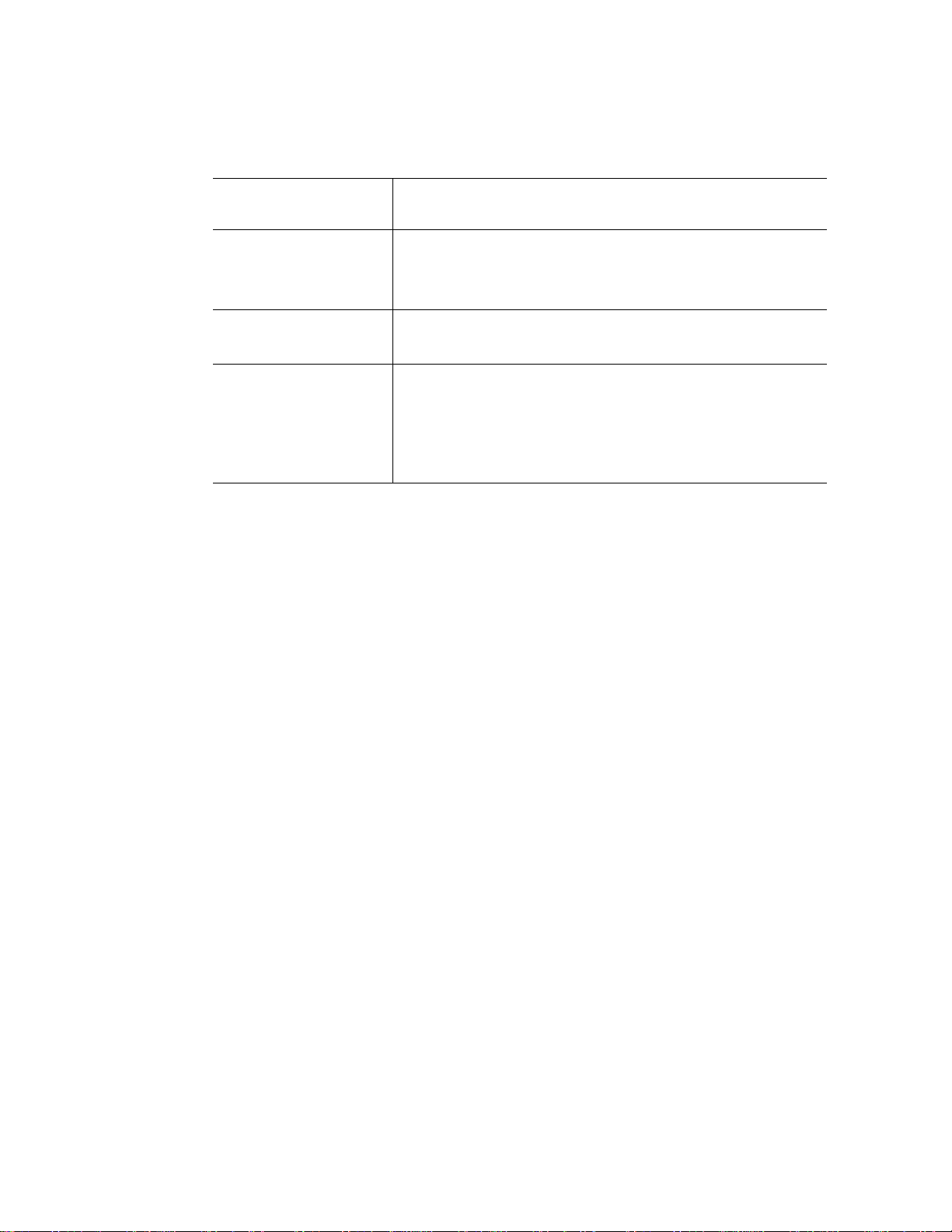
Table 1. Server System References
For this information or
For drivers Driver (for an extensive list of drivers available)
For firmware and BIOS
updates
For diagnostics test
software
software
Operating System Driver (for operating system driv er s)
http://support.intel.com/support/motherboards/server/S5500WB/
Firmware Update can be found at:
http://support.intel.com/support/motherboards/server/S5500WB/
Diagnostics: Platform Confidence Test (PCT)
Found at:
http://support.intel.com/support/motherboards/server/S5500WB/
and available on the Intel
ships with your system.
Use this Document or Software
®
Server Deployment Toolkit 3.0 CD that
2 Intel® Server System SR1690WB Service Guide
Page 21
2 Server System Features
Optical
Device
AF003210
This chapter briefly describes the main features of the Intel® Server System SR1690WB.
This chapter provides illustrations of the product, a list of the server system features, and
diagrams showing the location of important components and connections on the server
system.
®
Figure 1. Intel
Server System SR1690WB
Table 2 summarizes the features of the server system.
Table 2. Intel® Server System SR1690WB Feature Summary
Feature Description
Dimensions
• 1.69 inches (43mm) high
• 17.76 inches (451.17mm) wide
• 26.42 inches (671.08mm) deep
• 24.58 lbs (11.15kg) weight
Raw Storage Capacity System raw storage capacity is based on the HDD capacity and
number of HDDs used in the system. Raw storage capacity is the sum
of single HDD capacity used in system.
External Drive Bays Four hot-pluggable external drive bays
Hard Disk Drive
Supported
• 3.5-inch SATA, SAS HDD.
• 2.5-inch SATA, SAS HDD.
3
Page 22

Table 2. Intel® Server System SR1690WB Feature Summary
Feature Description
Processor
• Support for one or two Intel
®
Intel
Xeon® Processor 5600 series processors in FC-LGA 1366
Socket B package with up to 95 W Thermal Design Power (TDP).
• Supports future processor compatibility guidelines
4.8 GT/s, 5.86 GT/s, and 6.4 GT/s Intel
®
QPI).
(Intel
Meets EVRD11.1
Memory Capacity Expandable to 64 GB maximum.
Memory T ype
• 240-pin keyed support for 800/166/1333 MT/s ECC Registered
(RDIMM) or Unbuffered (UDIMM) DDR3 memory.
• 8 DIMMs total across six memory channels (three channels per
processor in a 2:1:1 configuration).
No support for Quad-Rank x4 DIMMs
DIMM Slots Eight
®
Chipset Intel
System Connectors/
Headers
Chipset which includes the following components:
Intel® 5500 chipset IOH (IOH24D)
Intel® 82801Jx I/O Controller Hub (ICH10R)
• External I/O connectors:
– DB-15 Video connectors
– RJ-45 serial Port A connector
– RJ-45 connector for 10/100/1000 LAN
– One 2x USB 2.0 connectors
– One RJ-45 over USB for 10/100/1000 LAN
• Internal connectors/headers:
– Two USB 2x5 pin header, supporting up to four USB 2.0 ports
– One low-profile USB 2x5 pin
– One DH-10 Serial Port B header
– One 2x8 pin VGA header with presence detection to switch
from rear I/O video connector
– Six SATA II connectors
– Dual Connectors for Intel
– One RMM3 connector to support optional Intel
Management Module 3
– SATA SW RAID 5 Activation Key Connector
– One SSI-EEB compliant front panel header
®
Xeon® Processor 5500 series and
®
Quick Path Interconnect
®
I/O Expansion Module
®
Remote
System Fan Support
• Two sets of CPU fans
• Two sets of DIMM fans
Add-in Adapter
Support
4 Intel® Server System SR1690WB Service Guide
®
Intel
Server Board S5500WB SSI-compliant
One riser slot supporting full-height or low-profile 1U and 1U MD2 PCI
Express* x16 riser cards.
®
Two connectors supporting double- and single-wide Intel
Expansion Modules.
I/O
Page 23

Table 2. Intel® Server System SR1690WB Feature Summary
Feature Description
On-board Video On-board Server Engines* LLC Pilot II Controller
Matrox* G200 2D Video Graphics controller
Uses 8 MB of the BMC 32 MB DDR2 Memory
LAN Support Two 10/100/1000 ports provided by Intel
Acceleration Technology (I/OAT)
System Power Single 650-W power supply, 80 plus silver with PFC
System Management On-board Server Engines* LLC Pilot II Controller.
Integrated Baseboard Management Controller (Integrated BMC), IPMI
2.0 compliant
®
82576 with Intel® I/O
• Basic
– BMC Controller: ARC 926E-S microcontroller
– Super IO: Serial Port logic, legacy interfaces, LPC interface,
Port80
– Hardware Monitoring: Fan speed control and voltage
monitoring
• Advanced
– Video and USB compression and redirection
– NC-SI port, a high-speed sideband management interface
– Integrated Super I/O on LPC interface
Intel® Server System SR1690WB Service Guide 5
Page 24

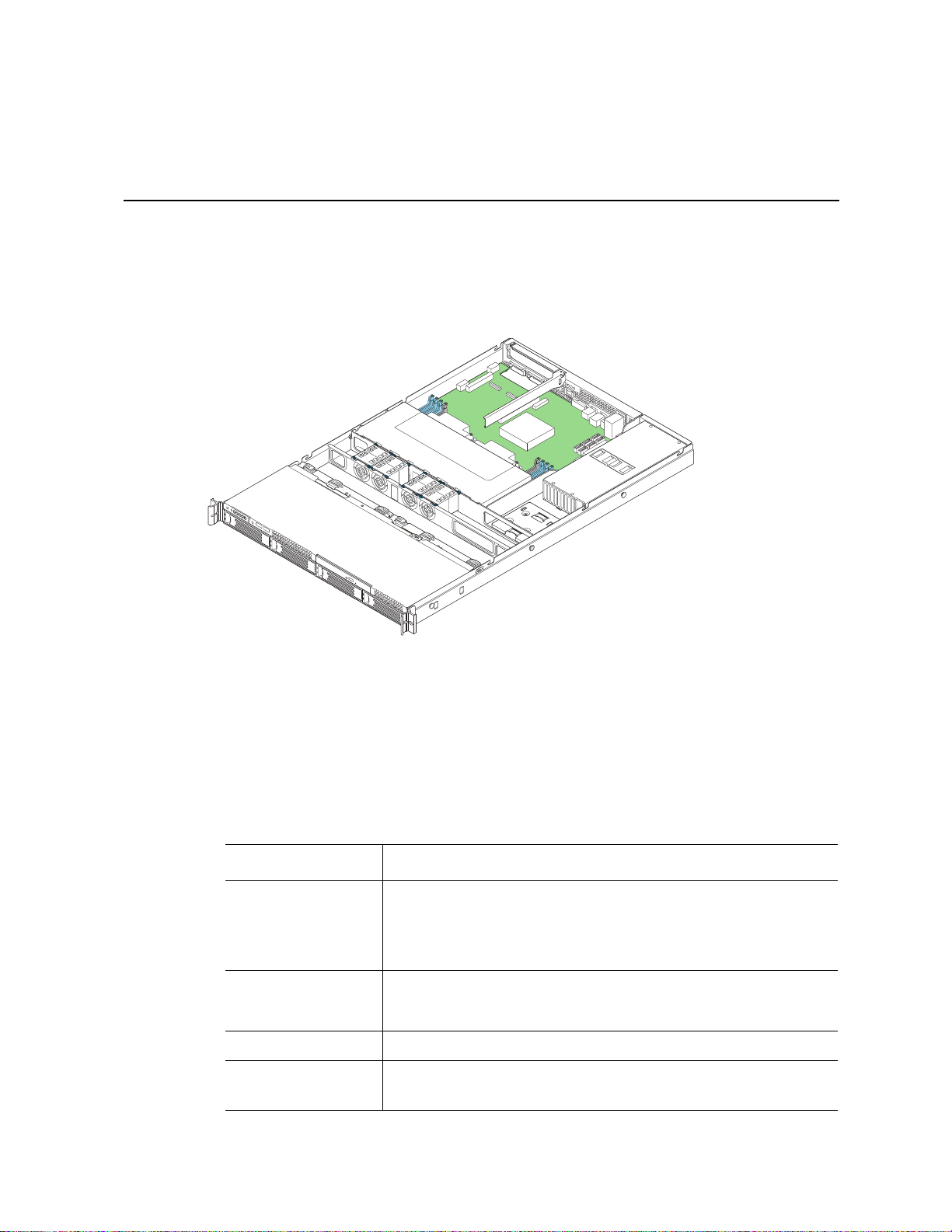
Cable Routing
When you add or remove components from your server system, make sure your cables are
routed correctly before reinstalling the server system cover. Use caution to make sure no
cables or wires are pinched and that the airflow from the fans is not blocked. Use the
following figures to determine the correct cable routing for the SR1690WB system.
6 Intel® Server System SR1690WB Service Guide
Page 25
AF003307
H
SES cable from RAID
Module to Backplane
I
Main Power
J
Aux. Signal Power
K
CPU Power
L
Power to Fans
M
Power to Optical Drive
N
Power to Backplane(2)
A
RAID Module
B
Battery Backup Unit
C
Power Supply
D
Backplane
E
Optical Drive
F
Fan Modules
Server Board
0
1
2
5
4
3
21 43
F
N
N
J
I
LL
M
K
G
D
B
A
E
RAID Card
H
G
Power from BBU
to RAID Module
O
IPMB Cable from Backplane
P
SGPIO Cable from Backplane
Q
SATA Data Cables
O
P
HDD 0
HDD 1 HDD 2 HDD 3
C
Q
Intel® Server System SR1690WB Service Guide 7
Page 26
Figure 2. Cable Routing
Optical
Device
AF003211
K
D
E
A
B
C
G
F
I
A
J
H
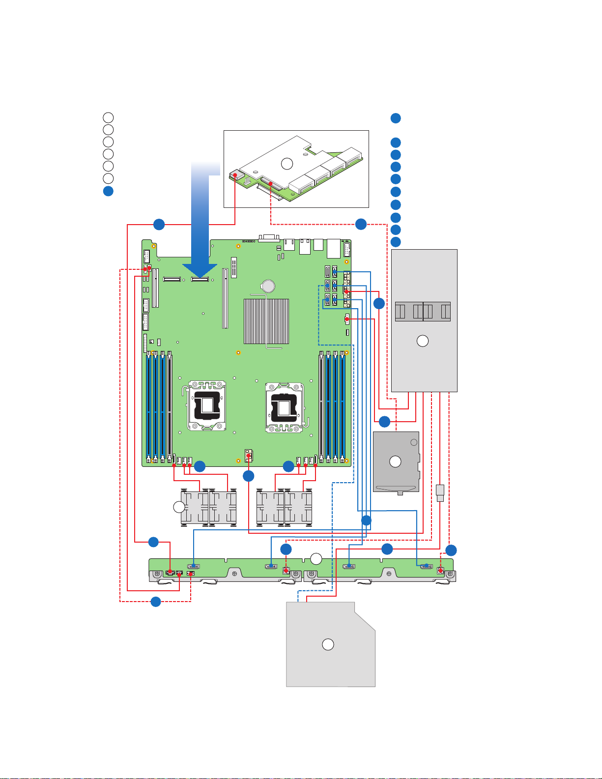
Chassis Component Identification
This section helps you identify the components of your server system. If you are near the
system, you can also use the Quick Reference Label provided on the inside of the chassis
cover to assist in identifying components.
Internal Components
A. Rack handles (two) G. PCI Express* x16 riser
B. Front Control Panel H. Mother board
C. Hot swap backplane I. 650W power supply unit
D. System Fans (CPU fans and Memory fans) J. Optional slimline optical drive
8 Intel® Server System SR1690WB Service Guide
E. Air Duct K. Hot swap HDD carrier
F. PCI Express* add-in card bracket
Figure 3. System Components
Page 27
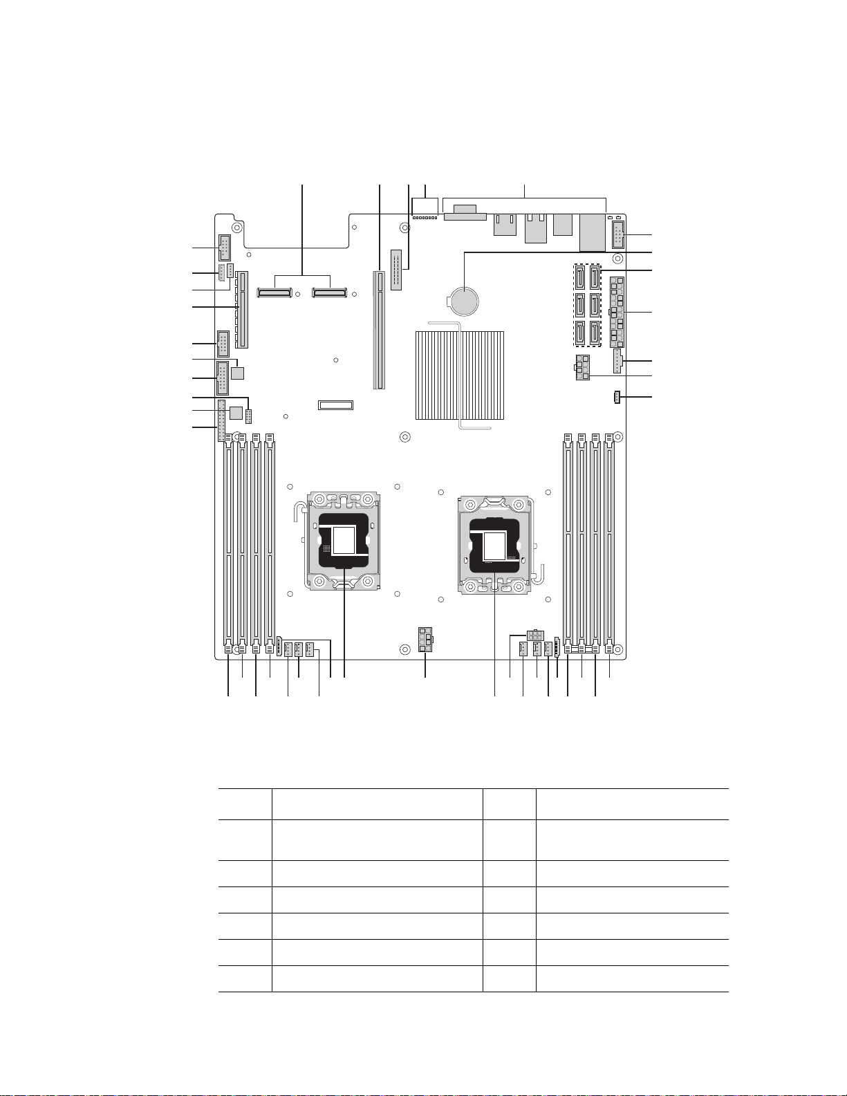
Server Board Connector and Component Locations
AF003212
EA B C
JJ
GG
LL
MM
PP
OO
NN
L
K
F
H
I
J
P
R
Q
S
T
ONM
D
U
FFEEDDCCBBAAZ
WXY
V
II
KK
HH
G
Description Description
A. Dual Intel
Connectors
B. PCI Express* x16 Gen2 X. Processor Socket 2
C. Remote Management Module 3 Y. 4-pin Fan Connector (CPU2)
D. POST Code LEDs Z. 4-pin Fan Connector (CPU2A)
®
I/O Expansion Module
W. 8-pin CPU Connector
E. External I/O AA. 4-pin Fan Connector (MEM2)
F. USB Connector BB. 8-pin Fan Connector (MEM2R)
Intel® Server System SR1690WB Service Guide 9
Page 28

Description Description
G. Battery CC. DIMM Slot D2
H. SATA Connectors 0~5 DD. DIMM Slot D1
I. 24-pin Power Connector EE. DIMM Slot E1
J. N/A FF. DIMM Slot F1
K. Aux Power (5-pin or 7-pin) GG. Front Panel Connector
L. RAID Key HH. HDD LED Header
M. DIMM Slot C1 II. Low-Profile USB Connector
N. DIMM Slot B1 JJ. Internal VGA Connector
O. DIMM Slot A1 KK. N/A
P. DIMM Slot A2 LL. USB Connector
Q. 8-pin Fan Connector (MEM1R) MM. Slot 1 PCI Express* x8 Gen2
R. 4-pin Fan Connector (MEM1) NN. SGPIO Connector
S. 4-pin Fan Connector (CPU1A) OO. IMPB Connector
T. 4-pin Fan Connector (CPU1) PP. Serial Port B
U. N/A
V. Processor Socket 1
Figure 4. Server Board Connector and Component Locations
10 Intel® Server System SR1690WB Service Guide
Page 29
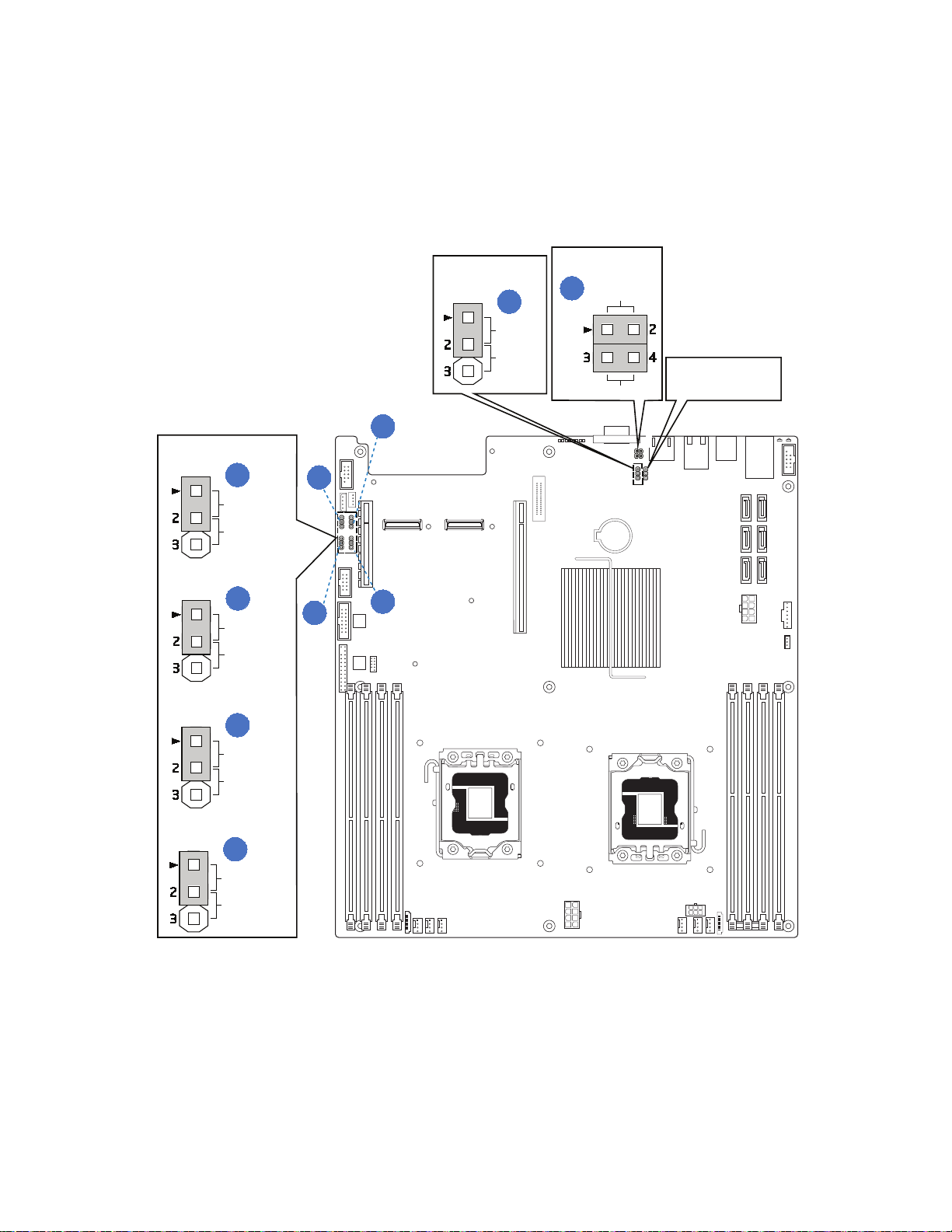
Configuration Jumpers
AF003049
F
A
B
C
D
ME BMC Update
Update
Normal
Clear
Password
Normal
Recovery
Normal
Reset BIOS
Normal
BMC Force Update
Password Clear
BIOS Recovery Mode
J1B5
J1B4
J1C3
J1C2
A
D
B
C
J6A2
DCD to DTR
DSR to DTR
E
Internal
External
J6A3
J7A2
Intel® Server System SR1690WB Service Guide 11
Page 30
Jumper Name Pins What happens at system reset...
J8C1: BMC
Force Update
Password
Clear(J1C2)
BIOS
Recovery(J1C3)
Reset BIOS
Configuration(J1
B4)
Video
Master(J6A3)e
Serial
Interface(J6A2)
1-2 BMC Firmware Force Update Mode -
Disabled (Default)
2-3 BMC Firmware Force Update Mode -
Enabled
1-2 Normal System Operation (Default)
2-3 Administrator and user passwords are
cleared on the next reset
1-2 Normal System Operation (Default)
2-3 The main system BIOS will not boot with
these pins jumpered. Note: the system boots
from EFI-bootable recovery media with a
recovery BIOS image.
1-2 Normal System Operation (Default)
2-3 Clear CMOS settings
1-2 Internal connector overrides
2-3 External connector overrides
1-2 DTR (Data Terminal Ready) mode
2-3 DCD (Data Carrier Detect) mode
None DSR (Data Set Ready) mode
Figure 5. Configuration Jumper Location
12 Intel® Server System SR1690WB Service Guide
Page 31

Intel® Light Guided Diagnostics
The server system contains numerous LEDs providing the following functions:
• The System Status LED on the front and back panels (see Figure 6) shows the
overall health of the system (green, blinking green, blinking amber, and off).
• The System Identification LED on the back panel (see Figure 6) helps identify the
server from among several servers. By default, the ID LED is off, and blue when
activated by button or software.
• DIMM Fault LEDs on the server board (see Figure 6) help identify failed and failing
DIMM slots. The DIMM fault LEDs turn on (amber) if there is a DIMM fault.
• POST Code Diagnostic LEDs on the server board (see Figure 6) change color or
state (off, green, red, amber) according to the POST sequence.
• The 5-V STBY LED on the server board (see Figure 6) is illuminated (green) when
AC power is applied.
• The Fan Fault LEDs on the server board (see Figure 6) help identify failed and
failing fans. The fan fault LEDs turn on (amber) if there is a fan fault.
Intel® Server System SR1690WB Service Guide 13
Page 32

AF003216
FLT_F
FLT_E FLT_D2
FLT_D1
FLT_A2
FLT_A1
FLT_C
FLT_B
A
B
C
D
E
G
F
A. Diagnostic LED G. CPU2 DIMM fault
LEDs
B. System Status LED
C. System ID LED
D. 5V Standby LED
E. CPU1 DIMM fault LEDs
F. Fan Fault LEDs
Figure 6. Light Guided Diagnostic LEDs
14 Intel® Server System SR1690WB Service Guide
Page 33

Back Panel Connectors
AF003217
A
B C D E
A. NIC1 connector with USB
ports 2, 5
C. NIC2 connector D. RJ-45 Serial B port
E. Internal Video Connector
B. USB ports 8, 9
Figure 7. Back Panel Connectors
The NIC LEDs at the right and left of each NIC provide the following information.
Table 3. NIC LED Descriptions
LED
NIC1/
NIC2
LED
State
Left
LED
Right
LED
LED State Description
Off No network connection
Solid Amber Network connection in place
Blinking Amber Transmit/receive activity
Off 10 Mbps connection (if left
LED is on or blinking)
Solid Amber 100 Mbps connection
Solid Green 1000 Mbps connection
Intel® Server System SR1690WB Service Guide 15
Page 34

RAID Support
The Intel® Server Board S5500WB provides an integrated SATA II host controller that
supports independent DMA operation on the six Ports and supports data transfer rates of
up to 3.0 Gb/Sec.
The ICH10R provides support for Intel
AHCI and integrated RAID functionality. The industry-leading RAID capability provides
high-performance RAID 0, 1, 5 and 10 functionality on up to six SATA ports.
The BIOS Setup utility provides multiple drive configuration options on the Advanced |
Mass Storage Controller Configuration setup page, some of which affect the ability to
configure RAID. The “Onboard SATA Controller” option is enabled by default. When this
option is enabled, the “SATA Mode” option can be set to ENHANCED mode,
COMPATIBILITY mode, AHCI mode or SW RAID mode. The modes affect the
configuration as follows:
• ENHANCED mode supports up to six SATA ports with IDE Native Mode.
• COMPATIBILITY mode supports up to four SATA ports[0/1/2/3] with IDE Legacy
mode and 2 SATA ports[4/5] with IDE Native Mode.
• AHCI mode supports all SATA ports using the Advanced Host Controller Interface
when the option is enabled.
®
Matrix Storage Technology, providing both
Note: For AHCI capability in EFI, the AHCI legacy Option ROM should be set to “disabled”.
• SW RAID mode supports configuration of SATA ports for RAID via RAID
configuration software.
For RAID 0, 1, and 10, enclosure management is provided through the SATA_SGPIO
connector on the server board when a cable is attached between this connector on the
server board and to the backplane or I2C interface.
®
If RAID 5 is desired, the optional Intel
installed. To enable RAID 5, this activation key is placed on the SATA Key connector that
is located at the right side of the server board. For information on how to install the Intel
RAID Activation Key AXXRAKSW5 accessory to enable RAID 5, see the
documentation that is included with the accessory kit.
RAID Activation Key AXXRAKSW5 can be
®
16 Intel® Server System SR1690WB Service Guide
Page 35

Front Panel of Server System
AF003218
A
I
HG
F
E
D
C
B
Standard Control Panel
The following diagram shows the features of the standard control panel.
Item Feature
A. Power/Sleep Button
B. System Reset Button
C. Power/Sleep LED
D. System NIC 1 Activity LED
E. System NIC 2 Activity LED
F. System Identification LED
G. System Status LED
H. System Identification Button
I. USB 2.0 connectors – Port 0 & 1
Figure 8. Front Control Panel - Intel
®
Server System SR1690WB
.
Table 4. Control Panel LED Functions
LED Color State Description
Power/
Sleep
LAN 1 and
LAN 2
Intel® Server System SR1690WB Service Guide 17
Green On Power On/ACPI S0 state
Green Blink Sleep /ACPI S1 state
- Off Power Off /ACPI S5 state
Green On LAN Link no Access
Green Blink LAN Activity
- Off No Link
Page 36

Table 4. Control Panel LED Functions
LED Color State Description
System ID Blue On Identify Active via command or button
Off No Identification
System
Status
Green On System Ready / No Alarm
Green Blink System ready, but degraded: redundancy lost such as
Amber On Critical Alarm: Critical power modules failure, critical
Amber Blink Non-Critical Alarm: Redundant fan failure, redundant
- Off AC power off: System unplugged AC power on:
Note: Blink rate is ~1 Hz at 50% duty cycle.
It is also off when the system is powered off (S5) or in a sleep state (S1).
The power LED sleep indication is maintained on standby by the chipset. If the system is
powered down without going through the BIOS, the LED state in effect at the time of
power off is restored when the system is powered on until the BIOS clear it.
If the system is not powered down normally, it is possible the Power LED will blink at the
same time the system status LED is off due to a failure or configuration change that
prevents the BIOS from running.
the power supply or fan failure; non-critical temp/
voltage threshold; battery failure; or predictive power
supply failure.
fans failure, voltage (power supply), critical
temperature and voltage
power module failure, non-critical temperature and
voltage
System powered off and in standby, no prior
degraded\non-critical\critical state
18 Intel® Server System SR1690WB Service Guide
Page 37

Rear of Server System
EFGHI
J
K
L
M
N
AF003220
A B C D
AF003221
CDE
A B
A. AC Power Receptacle I. RJ-45 Serial B port
B. NIC 1 connector J. NIC2 Connector
C. Top Cover Release Screw K. USB port 9
D. PCI Express* Add-in Card L. USB port 8
E. IO module external connector 2 (optional) M. USB port 5
F. IO module external connector 1 (optional) N. USB port 2
G. Management Network Interface (optional)
H. Internal Video Connector
Figure 9. Server System I/O Connector Locations
Peripheral Devices
The server system provides locations and hardware for installing hard drives and a
slimline optical drive. You must purchase the drives separately. The following figure
shows the available options.
Intel® Server System SR1690WB Service Guide 19
Page 38

A. Front Control Panel
B. Slimline Optical Drive
C. Hard Drive Bays HDD0~3
D. HDD Status LED
E. HDD Power LED
Hard Disk Drives
The server system ships with four hot-swap drive carriers for installing four SATA/SAS
Hard disk drives, both 3.5-inch or 2.5-inch HDDs.
For instructions on installing hard drives, see “Installing and Removing a Hot-swap Hard
Drive” on page -35.
Slimline Optical Drive latch
You can use a slimline optical drive latch with an optional optical drive. One slimline
optical drive latch is included with your server system; you must purchase the optical
drive separately.
Figure 10. Optional Peripherals
You can only insert or remove the slimline optical drive when the system power is turned
off. Drive in the optical drive bay is NOT hot-swappable. For installation instructions on
installing an optical drive, see “Installing or Removing a Slimline Optical Drive” on
page -38.
To use one of the drives provided by Intel, use the following order codes:
• SATA Slimline DVD Drive: AXXSATADVDROM
• SATA Slimline DVD Rewriteable Drive: AXXSATADVDRWROM
Rack-Mounted Systems
Your Int el® Server System SR1690WB can be mounted into a rack. Intel provides three
options to mount this server into a rack. When installing the chassis into a rack, Intel
recommends you install systems from the bottom of the rack to the top. In other words,
install the first system in the rack into the bottom position of the rack, the second system
in the second position from the bottom, and so on. Instructions for installing your chassis
into a rack are included in the rail kit.
20 Intel® Server System SR1690WB Service Guide
Page 39

Hardware Requirements
AF003226
DIMM A2
DIMM A1
DIMM B1
DIMM C1
DIMM D2
DIMM D1
DIMM E1
DIMM F1
Channel F
Channel E
Channel D
Channel C
Channel B
Channel A
To avoid integration difficulties and possible board damage, your system must meet the
requirements outlined below. For a list of qualified components, see the links under
“Server System References”.
Processor
Memory
The Intel® Server System SR1690WB supports one or two Intel® Xeon® Processor 5500
series and Intel
®
Xeon® Processor 5600 series with 95W Thermal Design Power (TDP) or
less and with a max data transfer rate of 6.4 GT/s. For a complete list of supported
processors, see the links under “Server System References”.
The Intel® Server System SR1690WB supports a DDR3-based memory subsystem. The
®
Server System SR1690WB supports two DIMMs per channel. The silkscreen on
Intel
the board for the DIMMs displays DIMM_A1, DIMM_A2, DIMM_B1, DIMM_B2,
DIMM_D1, DIMM_D2, DIMM_E1, DIMM_E2. See Figure 11. The minimal memory
population possible is DIMM_A1.
Figure 11. DIMM Configuration Diagram
For two slots per channel configurations, the server board requires DDR3 DIMMs within
a channel to be populated starting with the DIMM farthest from the processor. See the
following figure (Figure 12).
For a complete list of supported memory DIMMs, see the links under “Server System
References”.
Intel® Server System SR1690WB Service Guide 21
Page 40

Figure 12. Channel Slots Configuration
The Independent Channel Mode is the default Maximum Performance Mode preferred for
®
Xeon® Processor 5500 series and Intel® Xeon® Processor 5600 series based
Intel
platforms. All three channels may be populated in any order and have no matching
requirements. All channels must run at the same interface frequency, but individual
channels may run at different DIMM timings (RAS latency, CAS latency, and so forth).
Memory Sparing and Mirroring
The spare mode is not supported by Intel® Server System SR1690WB.
With memory mirroring, the system maintains two copies of all data in the memory
subsystem. If a DIMM fails, the data is not lost because the second copy of the data is
available from the mirrored DIMM in the opposite channel. The system will not fail due
to memory error unless both the primary and the mirrored copy of the data become corrupt
at the same time.
In a mirrored system, the maximum usable memory is one-half of the installed memory,
with a minimum of two DIMMs installed. Since the data is duplicated across DIMMs, it
means that up to one-half of the installed DIMMs are actively in use at any one time. The
remaining DIMMs are used for mirroring.
22 Intel® Server System SR1690WB Service Guide
Page 41

See the Intel® Server System S5500WB Technical Product Specification for additional
information regarding the memory sub-system.
Power Supply
TThe Power supply in SR1690WB system provides 650W at maximum. The power
supply must provide a minimum of 2.6 A of 5V standby current or the board will not boot.
Optional Hardware
Intel® RAID Activation Key
If RAID 5 is needed, you can install the optional Intel® RAID Activation Key
AXXRAKSW5. To enable RAID 5, this activation key is placed on the SATA Key
connector located at the left side of the server board. For information on how to install the
®
RAID Activation Key AXXRAKSW5 accessory to enable RAID 5, see the
Intel
documentation that is included with the accessory kit.
Intel® Remote Management Module 3
The RMM3 advanced management board serves two purposes. The first is to give the
customer the option to add a dedicated management 100-Mbit LAN interface to the
product. The second is to give additional flash space, enabling the Advanced Management
functions to support WS-MAN and CIMOM. The RMM3 comes with a third 10/100GbE
NIC that connects to the board. RMM3 management traffic can use the third NIC or NIC
1.
To install the RMM3 module, following the instruction in the RMM3 kit package, which
is purchased separately.
Intel® Server System SR1690WB Service Guide 23
Page 42

Intel® I/O Expansion Module
The Intel® Server System SR1690WB supports a variety of I/O Module options using 2x4
PCI Express* Gen2 Intel
®
I/O Expansion Module connectors on the rear of the server
board. It accommodates both the double-wide I/O expansion modules and the PCI
Express* Gen 1 I/O modules. Below is the list of supported I/O modules on SR1690WB:
Ta ble 5. List of Supported I/O Modules on SR1690WB
Product Code Description
AXX4SASMOD Intel
AXXGBIOMOD Dual Gigabit Ethernet I/O Expansion
AXXROMBSASMR Intel
AXXSASIOMOD External 4-port SAS I/O Expansion
AXX10GBIOMOD Dual-port 10 Gigabit Ethernet I/O
®
SAS Entry RAID I/O Expansion
Module: Provides 4-port pass through
SAS, entry-level RAID 0/1/1E, and
optional host RAID (4 internal por ts).
Module
®
Integrated RAID I/O Expansion
Module: Provides four internal ports,
full-featured SAS / SATA RAID 0,1,5,6
and striping capability for spans 10, 50,
60. You must order the optional backup
battery AXXRSBBU3 separately.
Module.
Expansion Module with CX4
connectors.
AXX4GBIOMOD2 Quad port Gigabit Ethernet I/O
Expansion Module based on the Intel
82576EB Gigabit Ethernet Controller.
AXXIBQDRMOD InfiniBand* I/O Expansion Module
Single Port QDR.
®
24 Intel® Server System SR1690WB Service Guide
Page 43

3 Hardware Installations and Upgrades
Before You Begin
Before working with your server product, pay close attention to the “Safety Information”
at the beginning of this manual.
Note: Whenever you service the system, you must first power down the server and unplug all
peripheral devices and the AC power cord.
Tools and Supplies Needed
• Phillips* (cross head) screwdrivers (#1 bit and #2 bit)
• Needle nosed pliers
• Pen or pencil
• Antistatic wrist strap and conductive foam pad (recommended)
System References
All references to the left, right, front, top, and bottom assume the reader is facing the front
of the server system as it would be positioned for normal operation.
Removing and Installing the System Cover
Removing the System Cover
You must operate the server system with the system cover in place to ensure proper
cooling. You must remove the top cover to add or replace components inside of the server.
None of the internal components are hot-swappable. Before you remove the server system
cover, power down the server and unplug all peripheral devices and the AC power cable.
Note: You may need a non-skid surface or a stop behind the server system to prevent the server
system from sliding on your work surface.
1. Remove the top cover screw (see letter “A”).
2. Loosen the screw at the rear of the chassis (see letter “B”).
3. Push rearward on the blue grip point at the front of the server.
25
Page 44

4. Slide the cover back until it stops and then lift the cover upward to remove it. See
Optical
Device
C
A
B
AF003222
letter “C”.
Figure 13. Removing the Server System Cover
Installing the System Cover
1. Observe the safety and ESD precautions at the beginning of this book. See “Safety
Information”.
2. Place the cover over the server system so that the side edges of the cover sit just
inside the server system sidewalls. Slide the cover forward (see letter “A” in
Figure 14).
3. Tighten the screw at the rear of the server (see letter “B”) and install the two screws
at the front of the server (see letter “C”).
26 Intel® Server System SR1690WB Service Guide
Page 45

Figure 14. Installing the Server System Cover
Optical
Device
C
A
B
AF003223
Removing and Installing the Processor Air Duct
The system requires the use of an air duct to direct airflow and sustain appropriate air
pressure. Always operate your server system with the air duct in place. The air duct is
required for proper airflow within the server system.
Removing the Processor Air Duct
1. Observe the safety and ESD precautions at the beginning of this book. See “Safety
Information”.
2. Power down the server and unplug all peripheral devices and the AC power cable.
3. Remove the server system cover. For instructions, see “Removing the System
Cover”.
4. Lift the processor air duct from its location behind the two system blower fans.
Intel® Server System SR1690WB Service Guide 27
Page 46

Figure 15. Removing the Processor Air Duct
Optical
Device
AF003224
Installing the Processor Air Duct
1. Observe the safety and ESD precautions at the beginning of this book. See “Safety
Information”.
2. Power down the server and unplug all peripheral devices and the AC power cable.
3. Remove the server system cover. For instructions, see “Removing the System
Cover”.
4. Lower the air duct into place; align the air duct side walls to the corresponding slots
on the bracket behind the four system blower fans and insert into position. Use
caution not to pinch or disengage cables that may be near or under the air duct.
28 Intel® Server System SR1690WB Service Guide
Page 47

Figure 16. Installing the Processor Air Duct
Optical
Device
AF003225
Installing and Removing Memory
The silkscreen on the board for the DIMMs displays DIMM_A1, DIMM_A2, DIMM_B1,
and DIMM_B2, DIMM_D1, DIMM_D2, DIMM_E1, and DIMM_E2 starting from the
inside of the board. For two slots per channel configurations, the server board requires
DDR3 DIMMs within a channel to be populated starting with the DIMM farthest from the
processor. The DIMM farthest from the processor per channel is in blue on boards.
Installing DIMMs
To install DIMMs, follow these steps:
1. Observe the safety and ESD precautions at the beginning of this book.
2. Turn off all peripheral devices connected to the server.
3. Turn off the server.
4. Disconnect the AC power cord from the server.
Intel® Server System SR1690WB Service Guide 29
Page 48

5. Remove the cover from the server and locate the DIMM sockets (see Figure 17).
D
C
B
A
E
AF003227
Figure 17. Installing the Memory
6. Make sure the clips at either end of the DIMM socket(s) are pushed outward to the
open position (see letter “A” in Figure 17).
7. Holding the DIMM by the edges, remove it from its anti-static package.
8. Position the DIMM above the socket. Align the two small notches in the bottom
edge of the DIMM with the keys in the socket (see letter “B” in Figure 17).
9. Insert the bottom edge of the DIMM into the socket (see letter “C” in Figure 17).
10. When the DIMM is inserted, push down on the top edge of the DIMM until the
retaining clips snap into place (see letter “D” in Figure 17). Make sure the clips are
firmly in place (see letter “E” in Figure 17).
11. Replace the server’s cover and reconnect the AC power cord.
Removing DIMMs
To remove a DIMM, follow these steps:
1. Observe the safety and ESD precautions at the beginning of this book.
2. Turn off all peripheral devices connected to the server. Turn off the server.
3. Remove the AC power cord from the server.
4. Remove the server's cover.
5. Gently spread the retaining clips at each end of the socket. The DIMM lifts from
6. Holding the DIMM by the edges, lift it from the socket, and store it in an anti-static
the socket.
package.
30 Intel® Server System SR1690WB Service Guide
Page 49

7. Reinstall and reconnect any parts you removed or disconnected to reach the DIMM
AF003228
B
A
sockets.
8. Replace the server's cover and reconnect the AC power cord.
Installing or Replacing the Processor
Note: Use the following instructions to install or replace a processor instead of using the
instructions that came with the processor.
Caution: Processor must be appropriate: If you install a processor that is inappropriate for your
server, you may damage the server board. See “Server System References” for a link to
the list of compatible processor(s).
ESD and handling processors: Reduce the risk of electrostatic discharge (ESD) damage
to the processor by doing the following: (1) Touch the metal chassis before touching the
processor or server board. Keep part of your body in contact with the metal chassis to
dissipate the static charge while handling the processor. (2) Avoid moving around
unnecessarily.
Installing the Processor
To install a processor, follow these instructions:
1. Observe the safety and ESD precautions at the beginning of this book. See “Safety
Information” for more information.
2. Turn off all peripheral devices connected to the server and turn off the server.
3. Disconnect the AC power cord from the server.
4. Remove the server's cover. See the document that came with your server chassis for
instructions on removing the server's cover.
5. Locate the processor socket and open the socket lever (see Figure 18).
Figure 18. Lifting the Load Lever
6. Open the load plate (see letter “A” in Figure 18 and letter “B” in Figure 18).
Intel® Server System SR1690WB Service Guide 31
Page 50

Figure 19. Open the Load Plate
AF003229
B
A
AF003292
7. Remove the socket protective cover (see Figure 19).
8. Take the processor out of the box and remove the protective shipping cover
(Figure 20).
Figure 20. Removing the socket
32 Intel® Server System SR1690WB Service Guide
Page 51

Note: Do not touch the socket pins; they are very sensitive and easily damaged.
AF003293
B
A
AF003294
C
B
A
9. Align the processor cutouts to match the two socket pins, and then insert the
processor into the socket as shown in Figure 21.
Figure 21. Aligning the Processor
10. Close the load plate (see the letter “A” in Figure 22), close the socket lever and
ensure the load plate tab engages under the socket lever when fully closed. (See
letter “B” and “C” in Figure 22)
Figure 22. Close the Load Plate and Socket Lever
Note: Make sure the alignment triangle mark and the alignment triangle cutout align correctly.
To assist in package orientation and alignment with the socket:
Intel® Server System SR1690WB Service Guide 33
Page 52

Installing the Heat Sink(s)
AF003295
2
3
1
4
C
B
A
1. If a protective film covers the thermal interface material (TIM) on the underside of
the heat sink, remove the protective film.
2. Align heat sink fans to the front and back of the chassis for correct airflow. Airflow
goes from front-to-back of chassis.
3. Each heat sink has four captive fasteners and should be tightened as shown.
4. Using a #2 Phillips* screwdriver, finger-tighten each fastener diagonally according
to the white-circled numbers (see Figure 23).
5. Securely re-tighten each fastener again in the same order as performed in Step 4.
6. Attach fan power cable to server board as shown below.
Figure 23. IU Reference Heat sink Assembly
7. Reinstall and reconnect any parts you removed or disconnected to reach the
processor sockets.
8. Replace the server’s cover and reconnect the AC power cord. See the
documentation that came with your server chassis for instructions on installing the
server’s cover.
Replacing a Processor
34 Intel® Server System SR1690WB Service Guide
1. Observe the safety and ESD precautions at the beginning of this book.
2. Turn off all peripheral devices connected to the server. Turn off the server.
Page 53

3. Remove the AC power cord from the server.
4. Remove the server's cover.
5. Unplug the processor fan cable from the server board.
6. Loosen the four captive screws on the corners of the heat sink.
7. Twist the heat sink slightly to break the seal between the heat sink and the
processor.
8. Lift the heat sink from the processor. If it does not pull up easily, twist the heat sink
again. Do not force the heat sink from the processor. Doing so could damage the
processor.
9. Lift the processor lever.
10. Raise the CPU load plate.
11. Remove the processor.
12. If installing a replacement processor, see “Installing the Processor”. Otherwise,
install the protective socket cover over the empty processor socket and reinstall the
chassis cover.
Installing and Removing a Hot-swap Hard Drive
You can install up to two fixed SATA drives in the Intel® Server System SR16WB90
Service Guide. See “Server System References” for a link to a list of supported hardware.
Caution: If you install less than four drives or devices, the empty drive bays must be occupied by
carriers with drive blanks to maintain proper system cooling.
To avoid possible damage to your server system, use only the drive carriers that came
with your system.
Installing a SAS or SATA Hot-swap Hard Disk Drive
Note: The server system does not support all hard drives. See “Server System References” for a
link to a list of supported hardware.
1. Open the latch at the front of the hard drive carrier (see letter “A”).
2. Pull out on the black lever and slide the carrier from the server system (see letter
“B”).
Intel® Server System SR1690WB Service Guide 35
Page 54

Figure 24. Pulling out the back lever
AF003302
A
B
AF003303
B
A
3. Remove the hard drive from its wrapper and place it on an antistatic surface.
4. Set any jumpers and/or switches on the drive according to the drive manufacturer's
instructions.
5. With the drive circuit-side down, position the connector end of the drive so that it is
facing the rear of the drive carrier.
6. Align the holes in the drive to the holes in the drive carrier and attach it to the
carrier with the screws that were attached to the drive blank.
Figure 25. 2.5 HDD Installation
36 Intel® Server System SR1690WB Service Guide
Page 55

Figure 26. 3.5 HDD Installation
AF003304
B
A
AF003305
B
A
7. With the black lever in the fully open position, slide the drive assembly into the
server system. The green latch at the front of the drive carrier must be to the right.
Do not push on the black drive carrier lever until the lever begins to close by itself.
8. When the black drive carrier lever begins to close by itself, push on it to lock the
drive assembly into place.
Figure 27. Locking the drive assembly
Intel® Server System SR1690WB Service Guide 37
Page 56

Removing a SAS or SATA Hot-swap Hard Disk Drive
1. Press in on the green latch at the front of the hard drive carrier. and pull out on the
black lever to slide the carrier from the server system.
2. Remove the four screws that attach the hard drive to the drive carrier. Lift the drive
from the carrier and store the drive in an anti-static bag.
3. With the black lever in the fully open position, slide the drive carrier into the server
system. The green latch must be to the right. Do not push on the black lever until
the lever begins to close by itself.
Note: All hard drive carriers must be installed in the server system and populated
either with a drive or without a drive to maintain system thermals.
4. When the black lever begins to close by itself, push on it to lock the drive carrier
into place.
Installing or Removing a Slimline Optical Drive
Caution: Slimline optical drives are NOT hot-swappable. Before removing or replacing the drive,
you must first take the server out of service, turn off all peripheral devices connected to
the system, turn off the system by pressing the power button, and unplug the AC power
cord from the system or wall outlet.
To maintain proper system cooling, if you do not install a device at this location, you must
install the provided filler blank.
Installing a Slimline Optical Drive
1. Remove the slimline drive bay filler blank, if installed.
38 Intel® Server System SR1690WB Service Guide
Page 57

Figure 28. Removing the Knockout in Bezel for Optical Opening
AF003311
B
A
AF003312
2. Obtain the optical drive, and the optical drive latch from system package.
3. Screw the latch to the optical drive, and plug in the composed SATA/SATA Power
cable, which is shipped in system package.
Figure 29. Attaching the Brackets to the Optical Drive
4. Lead the SATA/SATA Power cable through the optical drive bay before inserting
the drive.
Intel® Server System SR1690WB Service Guide 39
Page 58

5. Slide the optical drive assembly in through the front of the chassis, as shown by
B
A
AF003313
AF003314
B
A
letter “A in the following figure. The assembly will automatically be locked if the
drive assembly is in position.
6. Connect the SATA cable connector to SATA port 4 or 5 on server board.
7. Connect the SATA power connector to P6 connector from system power supply.
Optical
Device
Figure 30. Installing the Optical Drive into the Server System
40 Intel® Server System SR1690WB Service Guide
Page 59

Removing a Slimline Optical Drive
AF003322
1. Disconnect the SATA power from system power supply and SATA cable connector
from server board.
2. Press the optical latch and slide the optical drive assembly out of the chassis.
3. Install slimline drive bay filler blank, if no optical drive installed.
Installing and Removing the PCI Riser Assembly
Removing the PCI Riser Assembly
1. Disconnect any cables attached to any add-in cards.
2. Grasp the riser assembly and pull up to release it from the system.
Figure 31. Removing the PCI Riser Assembly from the Server System
Installing the PCI Riser Assembly
1. Lower the riser assembly into place (see letter “A”).
2. Align the two hooks in the riser assembly with the matching slots at the back of the
server system (see letter “B”).
Intel® Server System SR1690WB Service Guide 41
Page 60

Figure 32. Installing the PCI Riser Assembly
AF003323
B
A
3. Press down uniformly until the two hooks on the rear of the PCI riser assembly
engage the server system back panel slots. The riser card will seat into the matching
socket on the server board. Ensure the riser card is fully seated.
Installing and Removing a PCI Add-In Card
The following instructions describe how to install and remove a PCI add-in card.
Installing a PCI Add-In Card
Peripherals and add-in cards are not included in your system. You must purchase them
separately. The riser card supports a full-height or low-profile PCI Express* 2.0 x8 add-in
card.
1. After removing the PCI riser assembly from the server system, remove the screw
2. Insert the PCI card edge connector in the slot on the PCI riser.
that attaches the PCI bracket shield to the rear of the chassis to remove the shield.
Retain the screw.
42 Intel® Server System SR1690WB Service Guide
Page 61

Figure 33. Installing a PCI Card in a Riser Card
C
B
A
AF003324
B
A
AF003325
3. Insert the riser card with the attached PCI card into the PCI slot on the server board.
Press firmly on the riser card until it is fully seated. Be sure to press down on the
riser card, not on the PCI card.
Caution: Press the riser card straight down into the slot. Tipping the riser card while installing into
the slot may damage the riser card or slot on the server board.
4. Use the screw removed in step 1 to secure the riser card assembly to the chassis.
Removing a PCI Add-In Card
1. Remove the screw holding the add-in card in place (see letter “A”).
2. Remove the PCI add-in card from the riser card connector (see letter “B”).
Figure 34. Removing a PCI Card in a Riser Card
Intel® Server System SR1690WB Service Guide 43
Page 62

Removing and Installing the System Fans
Caution: The system fans are NOT hot-swappable. Before removing or replacing, you must first
take the server out of service, turn off all peripheral devices connected to the system, turn
off the system by pressing the power button, and unplug the AC power cord from the
system or wall outlet.
Note: The fans that are integrated into the power supply cannot be replaced separately. If one of
the fans in the power supply fails, you must replace the power supply.
The system fans are located in the front of the server system, which you can individually
replace if one of them fails. If a fan in the power supply fails, you must replace the power
supply. Use the following steps to replace a system fan.
Replacing the System Fans
1. Remove the processor air duct. For instructions, see “Removing the Processor Air
Duct”.
44 Intel® Server System SR1690WB Service Guide
Page 63

O
pti
Fan 4Fan 3Fan 2Fan 1
AF003309
21 43
B
A
A
Figure 35. Replacing the system fans
2. Disconnect the two 4-pin or one 8-pin system fan cables from the server board. See
letters “2” in the following figure.
3. Lift the failed fan from the module.
4. Remove the plastic screws from the failed fans and install them into the new fans.
Intel® Server System SR1690WB Service Guide 45
Page 64

Figure 36. Remove the screws from the fans
AF003308
5. Position the replacement fan so the connector on the fan is at the right and pointing
down.
6. With the fan oriented correctly, insert the fan into the fan module (see letter “3”),
and insert the fan cable into the matching connector on the server board. (see letter
“2”).
46 Intel® Server System SR1690WB Service Guide
Page 65

O
pti
Fan 4Fan 3Fan 2Fan 1
AF003310
21 43
B
A
B
Figure 37. Inserting the fan into the fan module
Installing and Removing the I/O Expansion Module(s)
Installing the I/O Expansion Module(s)
1. Squeeze the sides of the I/O expansion module cover to disengage it from the server
system back panel and remove it (see letter “A”).
Intel® Server System SR1690WB Service Guide 47
Page 66

AF003317
Optical
Device
A
Figure 38. Installing the I/O Expansion Module(s)
2. Attach the standoffs to the server board (see letter “A”) and attach the I/O shield
gasket to the module (see letter “B”).
3. Attach the I/O expansion module(s) to the server board (see letter “C”).
48 Intel® Server System SR1690WB Service Guide
Page 67

Optical
Device
B
A
AF003318
C
Figure 39. Attaching the I/O Expansion Module(s)
Removing the I/O Expansion Module(s)
1. Remove the I/O expansion module(s) from the server board (see letter “A”).
2. Remove the standoffs from the server board (see letter “B”).
3. Install the I/O expansion module cover into the system back panel (see letter “C”).
Intel® Server System SR1690WB Service Guide 49
Page 68

Installing and Removing the Intel® Remote
Optical
Device
A
AF003315
Management Module 3 and the Intel
Installing the Intel® RMM3 and Intel® RMM3 NIC
1. Squeeze the sides of the Intel®RMM3 NIC module cover to disengage it from the
server system back panel and remove it (see letter “A”)
®
RMM 3 NIC
Figure 40. Installing the Intel
2. Attach the bracket of Intel
3. Connect the Intel
4. Attach the Intel
®
RMM3 cable to the slot on server board (see letter “B”).
®
RMM3 module to rear chassis by two screws (see letter “C”).
®
RMM3 and Intel® RMM3 NIC
®
RMM3 NIC module by two screws (see letter “A”).
50 Intel® Server System SR1690WB Service Guide
Page 69

Optical
Device
A
B
AF003316
C
Figure 41. Attach the Intel® RMM3 module to rear chassis
Removing the Intel® RMM3 and Intel® RMM3 NIC
Use the reverse steps to remove the Intel® RMM3 module
1. Remove the two screws from rear chassis to loosen Intel
®
RMM3 board (see letter
“C”).
2. Plug out Intel
3. Install the Intel
®
RMM3 NIC module cable from the server board (see letter “B”).
®
RMM3 NIC module cover into the system back panel (see letter
“A”).
Replacing the Backplane Board
The instructions below describe how to replace the backplane board in the system.
Intel® Server System SR1690WB Service Guide 51
Page 70

Removing the Backplane Board
AF003300
Optical
Device
C
B
A
1. Disengage hard drives from the backplane board (see letter “A”).
2. Disconnect all cables from the backplane board.
3. Remove two screws on the top of backplane bracket (see letter “B”).
4. Pull out the backplane assembly vertically from the chassis (see letter “C”).
Figure 42. Removing the backplane board
Installing the Backplane Board
1. Lower the backplane assembly into the system (see letter “A”) and fix the
backplane assembly into fix position, aligning with two screw holes on chassis.
2. Tighten two screws to lock the backplane assembly in position (see letter “B”).
3. Connect data/power cables to the backplane connectors.
4. Engage hard drives back to the backplane (see letter “C”).
52 Intel® Server System SR1690WB Service Guide
Page 71

Figure 43. Installing the backplane board
AF003301
Optical
Device
B
C
A
Replacing the Server Board
Removing the Server Board
1. Remove the system air duct.
2. If installed, remove the memory, processor heat sinks, and processors from the
server.
3. If installed, remove the PCI riser assembly.
4. If installed, disconnect all SATA cables from the server board.
5. Disconnect the system fans cables from server board.
6. Disconnect all power cables coming from the power supply to the server board.
Intel® Server System SR1690WB Service Guide 53
Page 72

7. Remove the nine screws from the server board (see letter “A”) and lift the server
Optical
Device
AF003297
B
A
board from the server system (see letter “B”).
Figure 44. Removing the Server Board
8. Install the replacement server board. See “Installing the Server Board” on page -54.
Installing the Server Board
1. Place the server board into the server system as shown in the following figure (see
letter “A”).
2. Attach the server board with nine screws (see letter “B”).
54 Intel® Server System SR1690WB Service Guide
Page 73

Figure 45. Installing the Server Board
Optical
Device
AF003298
B
A
3. Re-connect all power cables coming from the power supply to the server board.
4. Re-connect the system fan cables to server board.
5. Re-connect all SATA cables to the server board.
6. Install the PCI riser assembly.
7. Install the memory, processor heat sinks, and processors.
8. Install the system air duct.
Intel® Server System SR1690WB Service Guide 55
Page 74

Replacing the Backup Battery
The lithium battery on the server board powers the RTC for up to 10 years in the absence
of power. When the battery starts to weaken, it loses voltage, and the server settings stored
in CMOS RAM in the RTC (for example, the date and time) may be wrong. Contact your
customer service representative or dealer for a list of approved devices.
Warning: Danger of explosion if battery is incorrectly replaced. Replace only with the same or
equivalent type recommended by the equipment manufacturer. Discard used batteries
according to manufacturer's instructions.
Advarsel: Lithiumbatteri - Eksplosionsfare ved fejlagtig håndtering. Udskiftning må kun ske med
batteri af samme fabrikat og type. Levér det brugte batteri tilbage til leverandøren.
Advarsel: Lithiumbatteri - Eksplosjonsfare. Ved utskifting benyttes kun batteri som anbefalt av
apparatfabrikanten. Brukt batteri returneres apparatleverandøren.
Va rn i ng : Explosionsfara vid felaktigt batteribyte. Använd samma batterityp eller en ekvivalent typ
som rekommenderas av apparattillverkaren. Kassera använt batteri enligt fabrikantens
instruktion.
Varoitus: Paristo voi räjähtää, jos se on virheellisesti asennettu. Vaihda paristo ainoastaan
laitevalmistajan suosittelemaan tyyppiin. Hävitä käytetty paristo valmistajan ohjeiden
mukaisesti.
56 Intel® Server System SR1690WB Service Guide
Page 75

1. Observe the safety and ESD precautions at the beginning of this book.
AF003299
2. Turn off all peripheral devices connected to the server. Turn off the server.
3. Disconnect the AC power cord from the server.
4. Remove the server's cover and locate the battery.
5. Insert the tip of a small flat bladed screwdriver, or an equivalent, under the tab in
the plastic retainer. Gently push down on the screwdriver to lift the battery.
6. Remove the battery from its socket.
Figure 46. Replacing the Backup Battery
7. Dispose of the battery according to local ordinance.
8. Remove the new lithium battery from its package, and, being careful to observe the
correct polarity, insert it in the battery socket.
9. Close the chassis.
10. Run Setup to restore the configuration settings to the RTC.
Replacing the Power Supply
Caution: The power supply is not hot-swappable. Before removing or replacing the power supply,
you must first take the server out of service, turn off all peripheral devices connected to
the system, turn off the system by pressing the power button, and unplug the AC power
cord from the system or wall outlet.
Removing the Power Supply
You can replace the power supply if it fails or if one of the fans integrated into it fails. To
replace the power supply, use the following instructions.
Intel® Server System SR1690WB Service Guide 57
Page 76

1. Disconnect all power supply cables including power at rear of chassis (see letter
AF003319
B
A
D
C
B
“A”).
2. Remove the three screws securing the power supply to the back panel (see letter
“B”).
Figure 47. Removing the Power Supply from the Server System
3. Lift the power supply up to clear the chassis tab (see letter “C”) and remove the
power supply by sliding it out (see letter “D”).
Installing the Power Supply
1. Insert the replacement power supply by first engaging the back panel (see letter
“A”).
58 Intel® Server System SR1690WB Service Guide
Page 77

2. Lower the front of the power supply into place behind the chassis tab (see letter
AF003320
A
D
C
B
C
“B”).
Figure 48. Installing the Power Supply into the Server System
3. Secure the power supply to the back panel with three screws (see letter “C”).
4. Connect all cables, including the power at the rear of the chassis (see letter “D”).
Installing and Removing the Rack Handles
Installing the Rack Handles
1. Align the rack handle with the holes on the side of the server system and attach the
rack handle with the three screws.
Intel® Server System SR1690WB Service Guide 59
Page 78

Figure 49. Installing the Rack Handle
AF003326
AF003327
2. Repeat step 1 on the opposite side of the server.
Removing the Rack Handles
1. Remove the three screws holding the rack handle in place, and remove the rack
handle from the server system.
Figure 50. Removing the Rack Handle
60 Intel® Server System SR1690WB Service Guide
Page 79

4 Server Utilities
Using the BIOS Setup Utility
This section describes the BIOS Setup Utility options, which is used to change server
configuration defaults. You can run the BIOS Setup with or without an operating system
being present. See “Server System References” for a link to the Intel
S5500WB Technical Product Specification where you can find details about specific
BIOS setup screens.
Starting Setup
You can enter and start BIOS Setup under several conditions:
• When you turn on the server, after POST completes the memory test.
• When you have moved the CMOS jumper on the server board to the “Clear CMOS”
position (enabled).
In the two conditions listed above, during the Power On Self Test (POST), you will see
this prompt:
Press <F2> to enter SETUP
®
Server Board
In a third condition, when CMOS/NVRAM is corrupted, you will see other prompts but
not the <F2> prompt:
Warning: CMOS checksum invalid
Warning: CMOS time and date not set
In this condition, the BIOS loads default values for CMOS and attempts to boot.
If You Cannot Access Setup
If you cannot access BIOS Setup, you might need to clear the CMOS memory. For
instructions on clearing the CMOS, see “Clearing the CMOS“.
Setup Menus
Each BIOS Setup menu page contains a number of features. Except for those features that
are provided only to display automatically configured information, each feature is
associated with a value field that contains user-selectable parameters. If a user has
adequate security rights, they can change these parameters. If a value cannot be changed
for any reason, the feature's value field is inaccessible.
61
Page 80

“Setup Menu Key Use” describes the keyboard commands you can use in the BIOS Setup
menus.
Table 6. Setup Menu Key Use
Key to Press Description
<F1> Pressing <F1> on any menu launches the general help window.
Left and right arrows The left and right arrow keys are used to move between the major menu
pages. The keys have no effect if a submenu or pick list is displayed.
Up arrow Select Item up - The up arrow is used to select the previous value in a
menu item's option list, or a value field pick list. Pressing <Enter>
activates the selected item.
Down arrow Select Item down - The down arrow is used to select the next value in a
menu item's option list, or a value field pick list. Pressing <Enter>
activates the selected item.
<F5> or <-> Change Value - The minus key or <F5> function key is used to change
the value of the current item to the previous value. This key scrolls
through the values in the associated pick list without displaying the full
list.
<F6> or <+> Change Value - The plus key or <F6> function key is used to change the
value of the current menu item to the next value . This ke y scrolls through
the values in the associated pick list without displaying the full list. On
106-key Japanese keyboards, the plus key has a different scan code
than the plus key on the other keyboard, but it has the same effect.
<Enter> Execute Command - The <Enter> key is used to activate submenus
when the selected feature is a submenu, or to display a pick list if a
selected feature ha s a v alue field, or to select a sub-fiel d f or multi- v alued
features like time and date. If a pick list is display ed, the <Enter> key will
undo the pick list, and allow another selection in the parent menu.
<Esc> Exit - The <Esc> key provides a mechanism for backing out of any field.
<F9> Setup Defaults - Pressing <F9> causes the following to display:
This key will undo the pressing of the <Enter> key. When the <Esc> key
is pressed while editing any field or selecting features of a menu, the
parent menu is re-entered. When the <Esc> key is pressed in any
submenu, the parent menu is re-entered. When the <Esc> key is
pressed in any major menu, the exit confirmation window is displayed
and the user is asked whether changes can be discarded.
Setup Confirmation
Load default configuration now?
[Yes] [No]
If “Yes” is selected and <Enter> is pressed, all Setup fields are set to
their default values. If “No” is selected and the <Enter> key is pressed, or
if <Esc> is pressed, the user is returned to where they were before <F9>
was pressed without affecting any existing field values.
62 Intel® Server System SR1690WB Service Guide
Page 81

Key to Press Description
<F10> Save and Exit - Pressing <F10> causes the following message to
Upgrading the BIOS
The upgrade utility allows you to upgrade the BIOS in flash memory. The code and data in
the upgrade file include the following:
• On-board system BIOS, including the recovery code, BIOS Setup Utility, and
strings.
• On-board video BIOS, and other option ROMs for devices embedded on the server
board.
Table 6. Setup Menu Key Use
display:
Setup Confirmation
Save Configuration changes and exit now?
[Yes] [No]
If “Yes” is selected and <Enter> is pressed, all changes are saved and
Setup is exited. If “No” is selected and <Enter> is pressed, or if <Esc> is
pressed, the user is returned to where they were before <F10> was
pressed without affecting any existing values.
• OEM binary area
• Microcode
• A way to change the BIOS language
Preparing for the Upgrade
The following steps explain how to prepare to upgrade the BIOS, including how to record
the current BIOS settings and how to obtain the upgrade utility.
In the unlikely event a BIOS error occurs during the BIOS upgrade process, you may need
to follow a recovery process to return the system to service. For additional information,
see “Server System References” for a link to the necessary firmware and BIOS updates
software and instructions.
Recording the Current BIOS Settings
1. Boot the computer and press <F2> when you see the message:
Press <F2> Key if you want to run SETUP
2. Write down the current settings in the BIOS Setup program.
Note: Do not skip step 2. You need these settings to configure your server at the end of the
procedure.
Intel® Server System SR1690WB Service Guide 63
Page 82

Obtaining the Upgrade
Download the BIOS image file to a temporary folder on your hard drive. See “Server
System References” for a link to the update software.
Note: Review the instructions and release notes provided in the readme file distributed with the
BIOS image file before attempting a BIOS upgrade. The release notes contain critical
information regarding jumper settings, specific fixes, or other information to complete the
upgrade.
Upgrading the BIOS
Download the BIOS image file to a temporary folder on your hard drive. See “Server
System References” for a link to the update software.
Caution: Do not power down the system during the BIOS update process! The system resets
automatically when the BIOS upgrade process completes. Doing so may corrupt the
system BIOS.
Note: You may encounter a CMOS Checksum error or other problem after reboot. If this
happens, shut down the system and boot it again. CMOS checksum errors require that you
enter Setup, check your settings, save your settings, and exit Setup.
Clearing the CMOS
If you cannot access the BIOS setup screens, you must use the CMOS Clear jumper to
reset the configuration RAM. The CMOS Clear jumper is located on jumper block at J1B4
on the server board.
1. Power down the system; do not disconnect the AC power.
2. Open the server.
3. Move the jumper from the normal operation position, at pins 1 and 2 to the CMOS
Clear Force Erase position, covering pins 2 and 3.
64 Intel® Server System SR1690WB Service Guide
Page 83

Figure 51. CMOS Recovery Jumper
AF003214
3
2
1-2: Default
2-3: Enabled
BMC Force Update
J1B5
3
2
1-2: Default
2-3: Password Clear
Password Clear
J1C2
3
2
1-2: Default
2-3: Clear CMOS
CMOS Clear
J1B4
4. Reconnect the AC power and power up the system.
5. When the system begins beeping, power it down and disconnect the AC power.
6. Return the CMOS Clear jumper to the spare location, covering pins 1 and 2.
7. Close the server chassis; reconnect the AC power and power up the system.
8. The CMOS is now cleared and you can reset it by going into the BIOS setup.
Resetting the Password
If the user or administrator password(s) is lost or forgotten, moving the password reset
jumper into the “clear” position clears both passwords. Before you can set a new
password(s), you must restore the password reset jumper to its original position. The
password clear jumper is located on jumper block at location J1C2 on the server board.
1. Power down the system and disconnect the AC power.
2. Open the server chassis.
3. Move the jumper from the normal operation position, Password Clear Protect, at
pins 1 and 2 to the Password Clear Erase position, covering pins 2 and 3.
Intel® Server System SR1690WB Service Guide 65
Page 84

4. Reconnect the AC power; power up the system.
AF003214
3
2
1-2: Default
2-3: Enabled
BMC Force Update
J1B5
3
2
1-2: Default
2-3: Password Clear
Password Clear
J1C2
3
2
1-2: Default
2-3: Clear CMOS
CMOS Clear
J1B4
5. Power down the system and disconnect the AC power.
6. Return the Password Reset jumper to the Password Protect position, covering pins
1 and 2. Reconnect AC power and power up the server.
7. The password is now cleared and you can reset it by going into the BIOS setup.
66 Intel® Server System SR1690WB Service Guide
Figure 52. Password Recovery Jumper
Page 85

Appendix A: Technical Reference
650-W Single Power Supply Input Voltages
• 100-127V at 47/63 Hz; 8.6 A max.
• 200-240V at 47/63 Hz; 4.3 A max.
650-W Single Power Supply Output Voltages
The following table lists the total wattage available from the power subsystem for each
voltage. Ensure your loads do not exceed the combined total wattage of 650 W. For
information about calculating the power usage for your configuration, see “Power Budget
Tool.”
Table 7. 650-W Single Power Supply Output Voltages
Voltage Maximum Continuous
+3.3 V 13.8A
+5 V 19.6A
+12 V1 11.3A
+12 V2 11.3A
+12 V3 9.1A
+12 V4 9.1A
-12 V 0.43A
+5 VSB 3.0A
1. Maximum continuous total DC output power should not exceed 650 watts.
2. Peak load on the combined 12V output shall not exceed 52A peak.
3. Maximum continuous load on the combined 12V output shall not exceed 47A
4. Peak total DC output power should not exceed 700 Watts peak.
5. Peak power and peak current loading shall be supported for a minimum of 12
seconds.
6. Combined 3.3V & 5V power shall not exceed 150W.
67
Page 86

System Environmental Specifications
Table 8. System Environmental Specifications
Temperature
Non-operating
Operating
Humidity
Non-operating 90% relative humidity (non-condensing) at 35°C.
Shock
Operating
Unpackaged
Packaged
Acoustic noise Sound Pressure: 55 dBA (rack mount) in an idle state at typical office
-40 ° to +70 °C.
10° C to 35° C (50° F to 90° F) with the maximum rate of change not to
exceed 10° C per hour
2.0 g, 11 msec, 1/2 sine
Trapezoidal, 25 g, velocity change 136 inches/sec
Non-palletized free fall at a height of 30 inches
ambient temperature. (23 +/- degrees C) Sound Power: 7.0 BA in an idle
state at typical office ambient temperature. (23 +/- 2 degrees C).
Electrostatic
discharge (ESD)*
+/-12 kV except I/O port +/-8 KV, per Intel Environmental Test Specification.
*The system requires the use of a shielded LAN cable to comply with Immunity
regulatory requirements. Use of non-shield cables may result in the product having
insufficient protection against electromagnetic effects, which may cause improper
operation of the product.
68 Intel® Server System SR1690WB Service Guide
Page 87

Appendix B: Intel® Server Issue Report
Form
Note: For the fastest service, please submit your form via the Internet.
Date Submitted: _______________________________________________________
Company Name: ______________________________________________________
Contact Name: ________________________________________________________
Email Address: _______________________________________________________
Intel Server Product: ___________________________________________________
Priority (Critical, Hot, High, Low): _______________________________________
Brief Problem Description. Provide a brief description below. See the last page for space
to include a detailed problem description.
____________________________________________________________________
____________________________________________________________________
____________________________________________________________________
____________________________________________________________________
____________________________________________________________________
Board / Chassis Information
Baseboard Revision - PBA#: _____________________________________________
Baseboard Serial Number: _______________________________________________
CPU1 Speed/Stepping/Spec: _____________________________________________
CPU2 Speed/Stepping/Spec: _____________________________________________
System BIOS Version: __________________________________________________
HSC Firmware Version: _________________________________________________
Chassis Model:________________________________________________________
®
Server System SR1690WB: __________________________________
Intel
69
Page 88

Other (Vendor/Model):___________________________________________
DIMM Configuration
DIMM A1 MB and Vendor / part number: __________________________________
DIMM A2 MB and Vendor / part number: __________________________________
DIMM B1 MB and Vendor / part number: __________________________________
DIMM C1 MB and Vendor / part number: __________________________________
DIMM D1 MB and Vendor / part number: __________________________________
DIMM D2 MB and Vendor / part number: __________________________________
DIMM E1 MB and Vendor / part number: __________________________________
DIMM F1 MB and Vendor / part number: __________________________________
Operating System Information
Operating System:_____________________________________________________
Version: _____________________________________________________________
Service Pack:_________________________________________________________
70 Intel® Server System SR1690WB Service Guide
Page 89

Add-in Card, Peripheral, Video, NIC
Check each box below as applicable, and provide the requested information:
Peripheral or Peripheral Description, Driver Revision, IRQ #, I/O Base Address, and FW
Peripheral Description
PCI Express*
Gen2 x8
On-board Video
Add-in Video
On-board NIC1 (10/
100/1000Mb/s)
On-board NIC2 (10/
100/1000Mb/s)
®
Intel
I/O
Expansion Module
Revision #NIC
Hard Drive Information
Drive Type (SATA/
SAS)
Driver
Revision
Make/Model IRQ
IRQ
FW
Revision
#
I/O Base
Address
FW
Revision
#
SATA_0
SATA_1
SATA_2
SATA_3
SATA_4
SATA_5
Management Information
On-Board Platform Instrumentation only ___________________________________
®
Remote Management Module _______________________________________
Intel
Intel® Server System SR1690WB Service Guide 71
Page 90

Complete Problem Description
In the space below, provide a complete description of the steps used to reproduce the
problem or a complete description of where the problem can be found. Please also include
any details on troubleshooting already done.
____________________________________________________________________
____________________________________________________________________
____________________________________________________________________
____________________________________________________________________
____________________________________________________________________
____________________________________________________________________
____________________________________________________________________
____________________________________________________________________
____________________________________________________________________
____________________________________________________________________
____________________________________________________________________
____________________________________________________________________
____________________________________________________________________
____________________________________________________________________
____________________________________________________________________
____________________________________________________________________
____________________________________________________________________
____________________________________________________________________
____________________________________________________________________
____________________________________________________________________
____________________________________________________________________
72 Intel® Server System SR1690WB Service Guide
Page 91

Appendix C: LED Decoder
AF003321
POST LED 7
POST LED 6
POST LED 5
POST LED 4
POST LED 0
POST LED 1
POST LED 2
POST LED 3
During the system boot process, the BIOS executes a number of platform configuration
processes, each of which is assigned a specific hex POST code number. As each
configuration routine is started, the BIOS displays the POST code to the POST Code
Diagnostic LEDs on the back edge of the server board. To assist in troubleshooting a
system hang during the POST process, the Diagnostic LEDs can be used to identify the
last POST process that was executed.
Each POST code is represented by the Eight amber Diagnostic LEDs. The POST codes
are divided into two nibbles, an upper nibble and a lower nibble. The upper nibble bits are
represented by Diagnostic LEDs #4, #5, #6, #7. The lower nibble bits are represented by
Diagnostics LEDs #0, #1, #2 and #3. Given the bit is set in the upper and lower nibbles,
then corresponding LED is lit. If the bit is clear, corresponding LED is off.
The Diagnostic LED #7 is labeled as “MSB”, and the Diagnostic LED #0 is labeled with
“LSB”.
Figure 53. Diagnostic LED Placement Diagram
Table 9. POST Progress Code LED Example
Upper Nibble LEDs Lo wer Nibble LEDs
LEDs
MSB LSB
LED #7LED #6LED #5LED #4LED #3LED #2LED #1LED
#0
73
Page 92

Table 9. POST Progress Code LED Example
8h 4h 2h 1h 8h 4h 2h 1h
Status ON OFF ON OFF ON OFF ON OFF
Results 1 01011 0 0
Ah Ch
• Upper nibble bits = 1010b = Ah; Lower nibble bits = 1100b = Ch; the two are
concatenated as ACh.
Table 10. Diagnostic LED POST Code Decoder
Diagnostic LED Decoder
Checkpoint 1 = On, 0= Off Description
Upper Nibble Lower Nibble
MSB LSB
8h 4h 2h 1h 8h 4h 2h 1h
LED #7 #6#5 #4 #3#2#1#0
Host Processor
0x10h 0 0 0 1 0000Power-on initialization of
the host processor
(bootstrap processor)
0x11h 0 0 0 1 0001 Host processor cache
initialization (including AP)
0x12h 0 0 0 1 001 0 Starting application
0x13h 0 0 0 1 0011SMM initialization
0x14h 0 0 0 1 0 1 0 0 Selection of Processor
0x15h 0 0 0 1 0 1 0 1 Switch an AP processor to
Chipset
0x21h 0 0 1 0001 0 Initializing a chipset
Memory
processor initialization
with least feature use as
Boot Strap Processor
become the new Boot
Strap Processor
component
74 Intel® Server System SR1690WB Service Guide
Page 93

Table 10. Diagnostic LED POST Code Decoder
0x22h 0 0 1 0001 0 Reading configuration
data from memory (SPD
on FBDIMM)
0x23h 0 0 1 00011Detecting presence of
0x24h 0 0 1 001 0 0 Programming timing
0x25h 0 0 1 001 0 1 Configuring memory
0x26h 0 0 1 00110 Optimizing memory
0x27h 0 0 1 00111Initializing memory, such
0x28h 0 0 1 0 1 000Testing memory
0xE4h 111001 0 0 BIOS cannot
0xE6h 11100110 DIMM(s) failed Memory
0xE8h 1110 1 000No memory available
memory
parameters in the memory
controller
parameters in the memory
controller
controller settings
as ECC init
communicate with DIMM
(serial channel hardware
failure
iBIST or Memory Link
Training failure
(system halted)
0xE9h 1110 1 001 Unsupported or invalid
DIMM configuration
(system halted)
0xEAh 1110 1 0 1 0 DIMM training sequence
failed (system halted)
0xEBh 1110 1 0 11Memory test failed
0xECh 1110 110 0 Unsupported or invalid
0xEDh 1110
0xEBh 1110 1 0 11DIMM with corrupted SPD
Intel® Server System SR1690WB Service Guide 75
110 1 Unsupported or invalid
(system halted)
DIMM configuration
(system halted)
DIMM configuration
(system halted)
data detected (system
halted)
Page 94

Table 10. Diagnostic LED POST Code Decoder
Intel® Quickpath Interconnect (QPI)
0xA0h 1 0 1 0 0000QPI Initialization
0xA1h 1 0 1 0 0001 QPI Initialization
0xA2h 1 0 1 0001 0 QPI Initialization
0xA3h 1 0 1 00011QPI Initialization
0xA4h 1 0 1 001 0 0 QPI Initialization
0xA5h 1 0 1 001 0 1 QPI Initialization
0xA6h 1 0 1 00110 QPI Initialization
0xA7h 1 0 1 00111QPI Initialization
0xA8h 1 0 1 0 1 000QPI Initialization
0xA9h 1 0 1 0 1 001 QPI Initialization
0xAAh 1 0 1 0 1 0 1 0 QPI Initialization
0xABh 1 0 1 0 1 0 11QPI Initialization
0xACh 1 0 1 0 110 0 QPI Initialization
0xADh 1 0
0xAEh 1 0 1 0 1110 QPI Initialization
0xAFh 1 0 1 0 1111QPI Initialization
Integrated Memory Controller (IMC)
0xB0h 1 0 11 0000Memory Initialization of
0xB1h 1 0 11 0001 Memory Initialization of
0xB2h 1 0 11 001 0 Memory Initialization of
0xB3h 1 0 11 0011Memory Initialization of
0xB4h 1 0 11 0 1 0 0 Memory Initialization of
0xB5h 1 0 11 0 1 0 1 Memory Initialization of
1 0 110 1 QPI Initialization
Integrated Memory
Controller
Integrated Memory
Controller
Integrated Memory
Controller
Integrated Memory
Controller
Integrated Memory
Controller
Integrated Memory
Controller
76 Intel® Server System SR1690WB Service Guide
Page 95

Table 10. Diagnostic LED POST Code Decoder
0xB6h 1 0 11 0 110 Memory Initialization of
Integrated Memory
Controller
0xB7h 1 0 11 0 111Memory Initialization of
0xB8h 1 0 11 1000Memory Initialization of
0xB9h 1 0 11 1001 Memory Initialization of
0xBAh 1 0 11 10 1 0 Memory Initialization of
0xBBh 1 0 11 10 11Memory Initialization of
0xBCh 1 0 11 110 0 Memory Initialization of
0xBDh 1 0 11 110 1 Memory Initialization of
0xBEh 1 0 11 1110 Memory Initialization of
Integrated Memory
Controller
Integrated Memory
Controller
Integrated Memory
Controller
Integrated Memory
Controller
Integrated Memory
Controller
Integrated Memory
Controller
Integrated Memory
Controller
Integrated Memory
Controller
0xBFh 1 0 11 1111Memory Initialization of
Intel® Server System SR1690WB Service Guide 77
Integrated Memory
Controller
Page 96

Table 10. Diagnostic LED POST Code Decoder
PCI Bus
0x50h 0 1 0 1 0000Enumerating PCI buses
0x51h 0 1 0 1 0001 Allocating resources to
PCI buses
0x52h 0 1 0 1 001 0 Hot Plug PCI controller
initialization
0x53h 0 1 0 1 0011Reserved for PCI bus
0x54h 0 1 0 1 0 1 0 0 Reserved for PCI bus
0x55h 0 1 0 1 0 1 0 1 Reserved for PCI bus
USB
0x56h 0 1 0 1 0 110 Initializing USB host
controllers
0x57h 0 1 0 1 0 111Detecting USB devices
0x58h 0 1 0 1 1000Resetting USB bus
0x59h 0 1 0 1 1001 Reserved for USB devices
ATA / ATAPI / SATA
0x5Ah 0 1 0 110 1 0 Resetting SATA bus and
all devices
0x5Bh 0 1 0 110 11Detecting the presence of
0x5Bh 0 1 0 1110 0 Enable SMART if
0x5Bh 0 1 0 111
SMBUS
0x5Eh 0 1 0 1 1110 Resetting SMBUS
0x5Fh 0 1 0 1 1111Reser ved for SMBUS
I/O Controller Hub
0x61h 0 110 0001 Initializing I/O Controller
Super I/O
0x63h 0 1100011Initiali zing Super I/O
Local Console
0x70h 0 111 0000Resetting the video
0 1 Reserved for ATA
ATA device
supported by ATA device
Hub
controller (VGA)
78 Intel® Server System SR1690WB Service Guide
Page 97

Table 10. Diagnostic LED POST Code Decoder
0x71h 0 111 0001 Disabling the video
controller (VGA)
0x72h 0 111 001 0 Enabling the video
controller (VGA)
0x73h 0 111 0011Reserved for video
controller (VGA)
Remote Console
0x78h 0 111 1000Resetting the console
controller
0x79h 0 111 1001 Disabling the console
0x7Ah 0 111 10 1 0 Enabling the console
0x7Bh 0 111 10 11Reserved for console
Keyboard (only USB)
0x90h 1 001 0000Resetting the keyboard
0x91h 1 001 0001 Disabling the keyboard
0x92h 1 001 001 0 Detecting the presence of
0x93h 1 001 0011Enabling the keyboard
0x94h 1 001 0 1 0 0 Clearing keyboard input
0x96h 1 001 0 1 0 1 Reserved for keyboard
Mouse (only USB)
0x98h 1 001 001 0 Resetting the mouse
0x99h 1 001 00
11Detecting the mouse
controller
controller
controller
the keyboard
buffer
0x9Ah 1 001 0 110 Detecting the presence of
0x9Bh 1 001 0 111Enabling the mouse
0x9Ch 1 001 001 0 Reserved for mouse
Serial Port
0xA8h 1 0 1 0 1 000Resetting the serial port
0xA9h 1 0 1 0 1 001 Disabling the serial port
0xAAh 1 0 1 0 1 0 1 0 Detecting the presence of
Intel® Server System SR1690WB Service Guide 79
mouse
the serial port
Page 98

Table 10. Diagnostic LED POST Code Decoder
0xABh 1 0 1 0 1 0 11Clearing serial port buffer
0xACh 1 0 1 0 110 0 Enabling serial port
0xADh 1 0 1 0 110 1 Reserved for serial port
Fixed Media
0xB0h 1 0 11 0000Resetting fixed media
device
0xB1h 1 0 11 0001 Disabling fixed media
0xB2h 1 0 11 001 0 Detecting presence of a
0xB3h 1 0 11 0011Enabling / configuring a
0xB4h 1 0 11 0 1 0 0 Reserved for fixed media
Removable Media
0xB8h 1 0 11 1000Resetting removable
0xB9h 1 0 11 1001 Disabling removable
0xBAh 1 0 11 10 1 0 Detecting presence of a
0xBCh 1 0 11 110 0 Enabling / configuring a
0xBDh 1 0 11 11
0 1 Reserved for removable
device
fixed media device (IDE
hard drive detection, and
so on)
fixed media device
media device
media device
removable media device
(IDE CDROM detection,
etc.)
removable media device
media device
Boot Device Selection (BDS)
0xD0 110 1 0000Entered the Boot Device
Selection phase (BDS)
0xD1 110 1 0001 Return to last good boot
device
0xD2 110 1 001 0 Set up boot device
0xD3 110 1 0011Connect boot device
0xD4 110 1 0 1 0 0 Attempt flash update boot
80 Intel® Server System SR1690WB Service Guide
selection policy
controller
mode
Page 99

Table 10. Diagnostic LED POST Code Decoder
0xD5 110 1 0 1 0 1 Transfer control to EFI
boot
0xD6 110 1 0 110 Trying boot device
selection
0xDF 110 1 1111Reserved for boot device
selection
Pre-EFI Initialization (PEI) Core
0xE0h 1110 0000Entered Pre-EFI
Initialization phase (PEI)
0xE1h 1110 0001 Started dispatching early
0xE2h 1110001 0 Initial memory found,
0xE3h 11100011Transfer control to the
PEI Modules
0xF0h 1 111 0000Install PEIM for Platform
0xF1h 1 111 0001 Detecting Platform Type
0xF2h 1 111 001 0Early Platform
0xF3h 1 111 0011PEI Modules initialized
Driver Execution Environment (DXE) Core
0xE4h 111001 0 0 Entered EFI driver
0xE5h 111001 0 1 Started dispatching
initialization modules
(PEIM)
configured, and installed
correctly
DXE Core
Status Codes
Initialization
execution phase (DXE)
drivers
0xE6h 11100110 Started connecting drivers
DXE Drivers
0xE7h 1110 110 1 Waiting for user input
0xE8h 111
0xE9h 1110 1 001 Entering BIOS setup
0xEAh 1110 110 0 Flash Update
0xEBh 1110 110 1 Legacy Option ROM
0xECh 1110 1 000DXE Drivers initialized
Intel® Server System SR1690WB Service Guide 81
0 1 000Checking password
Initialization
Page 100

Table 10. Diagnostic LED POST Code Decoder
0xEDh 1110 1 001 Transfer control to Boot
Device Selection (BDS)
0xEEh 1110 110 0 Calling Int 19. One beep
unless silent boot is
enabled.
0xEFh 1110 110 1 Unrecoverable boot failure
Pre-EFI Initialization Module (PEIM) / Recovery
0x30h 0 0 11 0000Crisis recovery has been
initiated because of a user
request
0x31h 0 0 11 0001 Crisis recovery has been
initiated by software
(corrupt flash)
0x34h 0 0 11 0 1 0 0 Loading crisis recovery
capsule
0x35h 0 0 11 0 1 0 1 Handing off control to the
0x36h 0 0 11 0 110 Begin crisis recovery
0x3Eh 0 0 11 1110 No crisis recovery capsule
0x3Fh 0 0 11 1111Crisis recovery capsule
crisis recovery capsule
detected
failed integrity check of
capsule descriptors
82 Intel® Server System SR1690WB Service Guide
 Loading...