

Page 1

Intel® Server System SR1680MV Service Guide
A Guide for Technically Qualified Assemblers of Intel® Identified Subassemblies/Products
Intel Order Number E74835-004
Page 2

Disclaimer
Information in this document is provided in connection with Intel® products. No license, express or implied, by
estoppel or otherwise, to any intellectual property rights is granted by this document. Except as provided in Intel's
Terms and Conditions of Sale for such products, Intel assumes no liability whatsoever, and Intel disclaims any
express or implied warranty, relating to sale and/or use of Intel products including liability or warranties relating to
fitness for a particular purpose, merchantability, or infringement of any patent, copyright or other intellectual property
right. Intel products are not designed, intended or authorized for use in any medical, life saving, or life sustaining
applications or for any other application in which the failure of the Intel product could create a situation where
personal injury or death may occur. Intel may make changes to specifications and product descriptions at any time,
without notice.
Intel server boards contain a number of high-density VLSI and power delivery components that need adequate
airflow for cooling. Intel's own chassis are designed and tested to meet the intended thermal requirements of these
components when the fully integrated system is used together. It is the responsibility of the system integrator that
chooses not to use Intel developed server building blocks to consult vendor datasheets and operating parameters to
determine the amount of airflow required for their specific application and environmental conditions. Intel Corporation
can not be held responsible if components fail or the server board does not operate correctly when used outside any
of their published operating or non-operating limits.
Intel, Intel Pentium, and Intel Xeon are trademarks or registered trademarks of Intel Corporation or its subsidiaries in
the United States and other countries.
* Other names and brands may be claimed as the property of others.
Copyright © 2009, Intel Corporation. All Rights Reserved
ii Intel® Server System SR1680MV Service Guide
Page 3

Intel® Server System SR1680MV Service Guide iii
Page 4

iv Intel® Server System SR1680MV Service Guide
Page 5

Preface
About this Manual
Thank you for purchasing and using the Intel® Server System SR1680MV.
This manual is written for system technicians who are responsible for troubleshooting,
upgrading, and repairing this server system. This document provides a brief overview of
the board features, a list of accessories or other components you may need,
troubleshooting information, and instructions on how to add and replace components on
the Intel
http://support.intel.com/support/motherboards/server/SR1680MV/.
Manual Organization
Chapter 1 provides a brief overview of the Intel® Server System SR1680MV. In this
chapter, you will find a list of the system features, photos of the product, and product
diagrams to help you identify components and their locations.
®
Server System SR1680MV. For the latest version of this manual, see
Chapter 2 provides instructions on adding and replacing components. Use this chapter for
step-by-step instructions and diagrams for installing or replacing components such as the
fans, power supply, drives, and other components.
Chapter 3 provides information on the cable connection. Use this chapter for detailed
information on the cable connections and connector locations.
Chapter 4 provides the description of the functions of all server board jumpers, and
connectors.
Chapter 5 describes the update process and configure features of the system BIOS.
Chapter 6 provides an overview of the embedded SATA RAID options and how to
configure RAID sets.
Chapter 7 provides instructions for installing rail kit to racks.
At the back of this book, you will find an issue report form, troubleshooting information,
regulatory information, and safety information.
Intel® Server System SR1680MV Service Guide v
Page 6

Product Contents, Order Options, and Accessories
Your Int el® Server System SR1680MV ships with the following items:
• One 1U chassis
• Two Server Boards
• Two Riser Cards
• Two 2.5-inch SATA HDD backplanes
• One left I/O board
• One right I/O board
• Four Hot-Swap 2.5-inch HDD trays
• Two NIC Boards
• One Power Distribution Board
• Six System Fans
• Four CPU Heatsinks
• One unit Rack Bracket
• Screws for 2.5-inch HDD
• One 1100-W power supply
In addition, you may need or want to purchase one or more of the following accessory
items for your server:
Processor, memory DIMMs, hard drive, and operating system.
For information about which accessories, memory, processors, and third-party hardware
were tested and can be used with your board, and for ordering information for Intel
products, see
http://support.intel.com/support/motherboards/server/SR1680MV/compat.htm.
Additional Information and Software
Documentation and software for this server product are available on the Intel Resource
CD-ROM that shipped with your Intel server product. You can obtain software updates
and additional information at the following Intel website:
http://support.intel.com/support/motherboards/server/SR1680MV/
vi Intel® Server System SR1680MV Service Guide
Page 7
Unless otherwise indicated in the following table, once on this webpage, type the
document or software name in the search field at the left side of the screen and select the
option to search “This Product.”
Additional Information and Software
For this information or
software
®
For in-depth technical
information about this
product, including BIOS
settings and chipset
information
If you just received this
product and need to
install it
Accessories or other Intel
server products
Hardware (peripheral
boards, adapter cards,
and so forth) and
operating systems that
were tested with this
product
Processors that were
tested with this product
DIMMs that were tested
with this product
For drivers Driver (for an extensive list of drivers available)
Intel
Server System SR1680MV Technical Product Specification
®
Intel
Server System SR1680MV Quick Start User's Guide in the
product box
Spares and Configuration Guide
Tested Hardware Operating Systems List
Supported Processors List
Supported Memory List
Operating System Driver (for operating system drivers)
Use this Document or Software
For firmware and BIOS
updates
To make sure your
system falls within the
allowed power budget
Intel® Server System SR1680MV Service Guide vii
Firmware Update Package
Power Budget Tool
Page 8

viii Intel® Server System SR1680MV Service Guide
Page 9

Safety Information
Important Safety Instructions
Read all caution and safety statements in this document before performing any of the
instructions. See also Intel Server Boards and Server Chassis Safety Information on the
®
Server Resource CD and/or at http://support.intel.com/support/motherboards/
Intel
server/sb/cs-010770.htm.
Wichtige Sicherheitshinweise
Lesen Sie zunächst sämtliche Warnund Sicherheitshinweise in diesem Dokument, bevor
Sie eine der Anweisungen ausführen. Beachten Sie hierzu auch die Sicherheitshinweise zu
Intel-Serverplatinen und Servergehäusen auf der Intel
http://support.intel.com/support/motherboards/server/sb/cs-010770.htm.
®
Server Resource CD oder unter
Consignes de sécurité
Lisez attention toutes les consignes de sécurité et les mises en garde indiquées dans ce
document avant de suivre toute instruction. Consultez Intel Server Boards and Server
Chassis Safety Information sur le Intel
site http://support.intel.com/support/motherboards/server/sb/cs-010770.htm.
®
Server Resource CD ou bien rendez-vous sur le
Instrucciones de seguridad importantes
Lea todas las declaraciones de seguridad y precaución de este documento antes de realizar
cualquiera de las instrucciones. Vea Intel Server Boards and Server Chassis Safety
Information en el Intel
motherboards/server/sb/cs-010770.htm.
®
Server Resource CD y/o en http://support.intel.com/support/
Intel® Server System SR1680MV Service Guide ix
Page 10

䞡㽕ᅝܼᣛᇐ
ᠻ㸠ӏԩᣛҸПࠡˈ䇋䯙䇏ᴀ᭛ḷЁⱘ᠔᳝⊼ᛣџ乍ঞᅝܼໄᯢDŽ
http://support.intel.com/support/motherboards/server/sb/CS-010770.htmϞⱘ,QWHO
6HUYHU%RDUGVDQG6HUYHU&KDVVLV6DIHW\,QIRUPDWLRQ˄lj,QWHO
᳡ࡵ఼ЏᵓϢ᳡ࡵ఼ᴎㆅᅝֵܼᙃNJ˅DŽ
x Intel® Server System SR1680MV Service Guide
Page 11

Warnings
Heed safety instructions: Before working with your server product, whether you are
using this guide or any other resource as a reference, pay close attention to the safety
instructions. You must adhere to the assembly instructions in this guide to ensure and
maintain compliance with existing product certifications and approvals. Use only the
described, regulated components specified in this guide. Use of other products /
components will void the UL listing and other regulatory approvals of the product and
will most likely result in noncompliance with product regulations in the region(s) in which
the product is sold.
System power on/off: The power button DOES NOT turn off the system AC power. To
remove power from system, you must unplug the AC power cord from the wall outlet.
Make sure the AC power cord is unplugged before you open the chassis, add, or remove
any components.
Hazardous conditions, devices and cables: Hazardous electrical conditions may be
present on power, telephone, and communication cables. Turn off the server and
disconnect the power cord, telecommunications systems, networks, and modems attached
to the server before opening it. Otherwise, personal injury or equipment damage can
result.
Electrostatic discharge (ESD) and ESD protection: ESD can damage disk drives,
boards, and other parts. We recommend that you perform all procedures in this chapter
only at an ESD workstation. If one is not available, provide some ESD protection by
wearing an antistatic wrist strap attached to chassis ground any unpainted metal surface on
your server when handling parts.
ESD and handling boards: Always handle boards carefully. They can be extremely
sensitive to ESD. Hold boards only by their edges. After removing a board from its
protective wrapper or from the server, place the board component side up on a grounded,
static free surface. Use a conductive foam pad if available but not the board wrapper. Do
not slide board over any surface.
Installing or removing jumpers: A jumper is a small plastic encased conductor that slips
over two jumper pins. Some jumpers have a small tab on top that you can grip with your
fingertips or with a pair of fine needle nosed pliers. If your jumpers do not have such a tab,
take care when using needle nosed pliers to remove or install a jumper; grip the narrow
sides of the jumper with the pliers, never the wide sides. Gripping the wide sides can
damage the contacts inside the jumper, causing intermittent problems with the function
controlled by that jumper. Take care to grip with, but not squeeze, the pliers or other tool
you use to remove a jumper, or you may bend or break the pins on the board.
Intel® Server System SR1680MV Service Guide xi
Page 12

xii Intel® Server System SR1680MV Service Guide
Page 13

Table of Contents
Preface .........................................................................................................................v
About this Manual .................................................................................................................. v
Manual Organization ..............................................................................................................v
Product Contents, Order Options, and Accessories ............................................................. vi
Additional Information and Software ..................................................................................... vi
Safety Information ..................................................................................................... ix
Important Safety Instructions ................................................................................................ ix
Wichtige Sicherheitshinweise ............................................................................................... ix
Consignes de sécurité ..........................................................................................................ix
Instrucciones de seguridad importantes ............................................................................... ix
Warnings ............................................................................................................................... xi
Chapter 1: Server System Features .......................................................................... 1
System Overview ...................................................................................................................3
Server Chassis Layout ..................................................................................................3
Front View Components ................................................................................................3
Back View Components ................................................................................................4
Buttons and System LEDs .....................................................................................................5
Front Panel Buttons and LEDs ......................................................................................5
Rear Panel Button and LEDs ........................................................................................6
LED Information .............................................................................................................6
Chapter 2: Hardware Installations and Upgrades ...................................................9
Before You Begin ...................................................................................................................9
Tools and Supplies Needed ..........................................................................................9
System References .....................................................................................................10
Power Off .....................................................................................................................10
Mid-Top Cover .....................................................................................................................11
Removing the Mid-Top Cover ......................................................................................11
Central Processing Unit (CPU) ....................................................................................12
Removing the Processor .............................................................................................13
Installing the Processor ...............................................................................................15
Removing the Heatsink ...............................................................................................16
Installing the Heatsink .................................................................................................17
System Memory ...........................................................................................................17
System Memory Channel Population Requirements for Memory RAS Modes ....................19
Independent Channel Mode ........................................................................................19
Mirrored Channel Mode ...............................................................................................19
Lockstep Channel Mode ..............................................................................................19
Intel® Server System SR1680MV Service Guide xiii
Page 14

Removing a DIMM ...................................................................................................... 21
Installing a DIMM ........................................................................................................ 21
Server Board Cage Module ......................................................................................... 23
Left and Right I/O Board Cage Modules ............................................................................. 25
Removing the Left I/O Board Cage Module ................................................................ 26
Power Supply Module ......................................................................................................... 27
Removing the Power Supply Module .......................................................................... 27
Installing the Power Supply Module ............................................................................ 28
Power Distribution Board ..................................................................................................... 28
Removing the Power Distribution Board ..................................................................... 29
Installing the Power Distribution Board ....................................................................... 29
Pluggable SATA Drive ......................................................................................................... 30
2.5-inch Pluggable SATA HDD ........................................................................................... 30
Removing a 2.5-inch Pluggable SATA HDD ............................................................... 30
Installing a 2.5-inch Pluggable SATA HDD ................................................................. 32
2.5-inch Pluggable HDD Backplane .................................................................................... 32
Removing an HDD Backplane .................................................................................... 33
Installing a 2.5-inch Pluggable SATA HDD Backplane ............................................... 33
System Fans ....................................................................................................................... 33
Removing a System Fan ............................................................................................. 34
Installing a System Fan ............................................................................................... 35
Air Duct ................................................................................................................................ 35
Removing the IOB Air Duct ......................................................................................... 35
Installing Air Ducts ...................................................................................................... 36
PCI-E Cage ......................................................................................................................... 36
Removing a PCI-E Cage ............................................................................................. 36
Installing a PCI-E Cage ............................................................................................... 38
Daughter Cards (Optional) .......................................................................................... 38
Removing the IO Expansion Module ........................................................................... 39
Installing the IO Expansion Module ............................................................................. 41
Chapter 3: Cable Connections .................................................................................43
Connectors and Pin 1 Locations ................................................................................. 43
Cable Connections ...................................................................................................... 44
Chapter 4: Connectors, Jumpers, and LEDs ..........................................................47
Connector and Component Locations of Server Board ....................................................... 47
Connector and Component Locations of IO Board ............................................................. 49
Connector and Component Locations of NIC Board ........................................................... 50
Connectors and Components of Front Panel ...................................................................... 51
10 GB IO Card (Optional Daughter Card) ........................................................................... 52
InfiniBand Card (Optional Daughter Card) .......................................................................... 53
Connector and Component Locations of HDD Backplane .................................................. 54
Connectors and Component Locations of PDB ................................................................... 55
xiv Intel® Server System SR1680MV Service Guide
Page 15

Chapter 5: BIOS Setup and Configuration ............................................................. 59
BIOS Setup Utility ........................................................................................................59
Entering the BIOS Setup Utility ...................................................................................60
Main Menu ...................................................................................................................63
Advanced Menu ...........................................................................................................64
SATA Configuration Submenu ....................................................................................68
Super IO Chipset Submenu .........................................................................................73
USB Configuration Submenu ......................................................................................75
USB Mass Storage Device Configuration Submenu ...................................................77
PCI Express* Configuration Submenu ........................................................................79
IPMI Configuration Submenu ......................................................................................80
View BMC System Event Log Submenu .....................................................................82
Remote Access Configuration Submenu .....................................................................83
Boot Menu ...................................................................................................................84
Boot Setting Configuration Submenu ..........................................................................85
Boot Device Priority Submenu .....................................................................................87
Removable Drives Submenu .......................................................................................88
CD/DVD Drives Submenu ...........................................................................................89
Security Menu ..............................................................................................................90
Trusted Computing Submenu ......................................................................................92
Exit Menu .....................................................................................................................94
BIOS Updates ..............................................................................................................95
ROM Flash ..................................................................................................................95
Chapter 6: Embedded SATA RAID .......................................................................... 97
Enabling RAID in the BIOS Setup ...............................................................................97
Chapter 7: Installing the Rackmount Rail Kits ....................................................... 99
Procedure to install the rail kit ............................................................................................100
Appendix A: Intel® Server Issue Report Form ..................................................... 103
Appendix B: Troubleshooting ...............................................................................109
Resetting the System .........................................................................................................109
Problems following Initial System Installation ....................................................................109
First Steps Checklist ..................................................................................................109
Hardware Diagnostic Testing .............................................................................................110
Verifying Proper Operation of Key System Lights .....................................................111
Confirming Loading of the Operating System ............................................................111
Specific Problems and Corrective Actions .........................................................................111
Power Light Does Not Light .......................................................................................111
No Characters Appear on Screen .............................................................................112
Characters Are Distorted or Incorrect ........................................................................112
System Cooling Fans Do Not Rotate Properly ..........................................................113
Cannot Connect to a Server ......................................................................................113
LED Information .........................................................................................................114
Intel® Server System SR1680MV Service Guide xv
Page 16

BIOS POST Beep Codes .......................................................................................... 114
Appendix C: Installation/Assembly Safety Instructions .....................................117
English ............................................................................................................................... 117
Deutsch ............................................................................................................................. 119
Français ............................................................................................................................. 121
Español ............................................................................................................................. 123
Italiano ............................................................................................................................... 125
Appendix D: Safety Information ............................................................................129
English ............................................................................................................................... 129
Server Safety Information ......................................................................................... 129
Safety Warnings and Cautions .................................................................................. 129
Intended Application Uses ........................................................................................ 130
Site Selection ............................................................................................................ 130
Equipment Handling Practices .................................................................................. 130
Power and Electrical Warnings ................................................................................. 131
Access Warnings ...................................................................................................... 131
Electrostatic Discharge (ESD) ................................................................................... 132
Other Hazards ........................................................................................................... 132
Deutsch ............................................................................................................................. 133
Sicherheitshinweise für den Server ........................................................................... 133
Sicherheitshinweise und Vorsichtsmaßnahmen ....................................................... 134
Zielbenutzer der Anwendung .................................................................................... 134
Standortauswahl ....................................................................................................... 134
Handhabung von Geräten ......................................................................................... 135
Warnungen zu Netzspannung und Elektrizität .......................................................... 136
Warnhinweise für den Systemzugang ....................................................................... 136
Elektrostatische Entladungen (ESD) ......................................................................... 137
Andere Gefahren ....................................................................................................... 138
Français ............................................................................................................................. 139
Consignes de sécurité sur le serveur ........................................................................ 139
Sécurité: avertissements et mises en garde ............................................................. 139
Domaines d’utilisation prévus ................................................................................... 140
Sélection d’un emplacement ..................................................................................... 140
Pratiques de manipulation de l’équipement .............................................................. 140
Alimentation et avertissements en matière d’électricité ............................................ 141
Avertissements sur l’accès au système .................................................................... 141
Décharges électrostatiques (ESD) ............................................................................ 142
Autres risques ........................................................................................................... 142
Español ............................................................................................................................. 143
Información de seguridad del servidor ...................................................................... 143
Advertencias y precauciones sobre seguridad ......................................................... 143
Aplicaciones y usos previstos ................................................................................... 144
Selección de la ubicación .......................................................................................... 144
xvi Intel® Server System SR1680MV Service Guide
Page 17

Manipulación del equipo ............................................................................................145
Advertencias de alimentación y eléctricas .................................................................145
Advertencias el acceso al sistema ............................................................................146
Descarga electrostática (ESD) ..................................................................................147
Otros peligros ............................................................................................................147
简体中文 .....................................................................149
Appendix E: Regulatory and Certification Information ....................................... 155
Product Regulatory Compliance ........................................................................................155
Product Safety Compliance .......................................................................................155
Product EMC Compliance - Class A Compliance ......................................................156
Product Ecology Compliance ....................................................................................157
Certifications / Registrations / Declarations ...............................................................157
Product Regulatory Compliance Markings ................................................................158
Rack Mount Installation Guidelines ...................................................................................163
Power Cord Usage Guidelines ..........................................................................................164
Electromagnetic Compatibility Notices ..............................................................................166
FCC Verification Statement (USA) ............................................................................166
ICES-003 (Canada) ...................................................................................................167
CE Declaration of Conformity (Europe) .....................................................................167
VCCI (Japan) .............................................................................................................167
BSMI (Taiwan) ...........................................................................................................168
KCC (Korea) ..............................................................................................................168
Regulated Specified Components .....................................................................................168
Appendix F: Warranty ............................................................................................ 171
Appendix G: Getting Help ...................................................................................... 173
Intel® Server System SR1680MV Service Guide xvii
Page 18

xviii Intel® Server System SR1680MV Service Guide
Page 19

List of Figures
Figure 1. Intel® Server System SR1680MV with 2.5-inch Pluggable HDDs.............................. 1
Figure 2. Layout of Server Chassis with 2.5-inch Pluggable HDDs .......................................... 3
Figure 3. Front View of Server with 2.5-inch Pluggable HDDs.................................................. 4
Figure 4. Back View .................................................................................................................. 4
Figure 5. Front Panel Buttons and LEDs of Server................................................................... 5
Figure 6. Back View LEDs and Buttons of Two I/O Boards ...................................................... 6
Figure 7. Pressing the Power Button....................................................................................... 10
Figure 8. Unplugging the Power Cord..................................................................................... 11
Figure 9. Removing the Mid-Top Cover .................................................................................. 12
Figure 10. Location of Processors........................................................................................... 12
Figure 11. Opening the Load Plate ......................................................................................... 13
Figure 12. Lifting the Processor Out of the Socket.................................................................. 14
Figure 13. Placing on the PnP Cap......................................................................................... 14
Figure 14. Closing the Load Plate........................................................................................... 15
Figure 15. Pointing the Golden Corner Toward the Socket..................................................... 16
Figure 16. Removing the Heatsink.......................................................................................... 17
Figure 17. Location of System Memories................................................................................ 18
Figure 18. DIMM Socket Location........................................................................................... 18
Figure 19. Lifting the DIMM Out of the Socket ........................................................................ 21
Figure 20. Pressing the Retaining Clips Outward ................................................................... 22
Figure 21. Inserting the DIMM into the Socket........................................................................ 22
Figure 22. Server Board Cage Module with 2.5-inch Pluggable SATA HDD Location............ 23
Figure 23. Releasing the Locking Latch.................................................................................. 23
Figure 24. Pull the Locking Lever to Remove the Server Board Cage Module....................... 24
Figure 25. Left I/O Board Cage Module Location.................................................................... 25
Figure 26. Right I/O Board Cage Module Location ................................................................. 25
Figure 27. Slide the Locking Latch.......................................................................................... 26
Figure 28. Pull the Locking Lever to Remove the Left I/O Board Cage Module...................... 26
Figure 29. Power Supply Location .......................................................................................... 27
Figure 30. Removing the Power Supply Module..................................................................... 28
Figure 31. Power Distribution Board ....................................................................................... 28
Figure 32. Removing the Power Distribution Board ................................................................ 29
Figure 33. 2.5-inch Pluggable SATA HDD Location................................................................ 30
Figure 34. Release the Locking Lever..................................................................................... 31
Figure 35. Pull the Locking Lever to Remove the HDD Carrier............................................... 31
Figure 36. Release Screws and Lift the HDD Up.................................................................... 32
Figure 37. 2.5-inch Pluggable HDD Backplane Location ........................................................ 32
Figure 38. Remove the Screws and Lift the Backplane Up..................................................... 33
Figure 39. System Fans Location............................................................................................ 34
Figure 40. Lift a System Fan Up from I/O Board Cage Module............................................... 34
Figure 41. Lift Air Duct Up....................................................................................................... 35
Figure 42. PCI-E Cage Location ............................................................................................. 36
Intel® Server System SR1680MV Service Guide xix
Page 20

Figure 43. Lifting the PCI Cage from the I/O Board Module ................................................... 37
Figure 44. Removing the Expansion Card.............................................................................. 37
Figure 45. Securing the Slot Cover......................................................................................... 38
Figure 46. Removing the Riser Card ...................................................................................... 38
Figure 47. 10 GB IO Card Location ........................................................................................ 39
Figure 48. InfiniBand Card Location ....................................................................................... 39
Figure 49. Lifting the Module Upward from the IO Board ....................................................... 40
Figure 50. Removing the Module Upward from the IO Board................................................. 40
Figure 51. Locations of Connectors and Pin 1 on Server Board............................................. 43
Figure 52. Locations of Connectors and Pin 1 on I/O Board .................................................. 44
Figure 53. Connecting the System Fan Cables ...................................................................... 45
Figure 54. Connectors and Component Locations of Server Board ....................................... 47
Figure 55. Connectors and Component Locations of IO Boards ............................................ 49
Figure 56. Connectors and Component Locations of NIC Board............................................ 50
Figure 57. Connectors and Component Locations of Front Panel.......................................... 51
Figure 58. Connectors and Components of 10 GB IO Card ................................................... 52
Figure 59. Connectors and Components of InfiniBand Card .................................................. 53
Figure 60. Connectors and Components of 2.5-inch Pluggable HDD Backplane................... 54
Figure 61. Connectors and Component Locations of PDB..................................................... 55
Figure 62. Location of MISC Jumper ...................................................................................... 56
Figure 63. Location of ICH Function Jumper .......................................................................... 57
Figure 64. Overview of Rail Kit ............................................................................................... 99
Figure 65. Location Of Spring Screw Holes.......................................................................... 100
Figure 66. Secure screw into the rail hole............................................................................. 101
Figure 67. Secure the Rail to Racks ..................................................................................... 101
Figure 68. Slide The Server Into Racks................................................................................ 101
Figure 69. Push The Server To The End Of Racks .............................................................. 102
Figure 70. Secure The Server Ears To Racks...................................................................... 102
xx Intel® Server System SR1680MV Service Guide
Page 21

List of Tables
Table 1. Intel® Server System SR1680MV Feature Summary ..................................................2
Table 2. LED Information ..........................................................................................................6
Table 3. Ideal DIMM Installation Options for A-C Channels of Processor 1 ............................20
Table 4. Ideal DIMM Installation Options for D-F Channels of Processor 2 ............................20
Table 5. BIOS Setup Utility Screen Descriptions ....................................................................59
Table 6. Keyboard Command Bar Description ........................................................................60
Table 7. Main Menu of BIOS Setup Utility ...............................................................................63
Table 8. Main Menu Fields ......................................................................................................63
Table 9. Advanced Menu of BIOS Setup Utility .......................................................................64
Table 10. CPU Configuration Submenu ..................................................................................65
Table 11. CPU Configuration Submenu Fields .......................................................................66
Table 12. SATA Configuration Submenu1 ..............................................................................68
Table 13. SATA Configuration Submenu2 ..............................................................................69
Table 14. SATA Configuration Submenu3 ..............................................................................70
Table 15. SATA Configuration Submenu4 ..............................................................................71
Table 16. SATA Configuration Submenu Fields ......................................................................72
Table 17. Super IO Chipset Submenu ....................................................................................73
Table 18. SATA Configuration Submenu Fields ......................................................................74
Table 19. USB Configuration Submenu ..................................................................................75
Table 20. USB Configuration Submenu Fields ........................................................................75
Table 21. USB Mass Storage Device Configuration Submenu ...............................................77
Table 22. USB Mass Storage Device Configuration Submenu Fields ....................................78
Table 23. PCI Express* Configuration Submenu ....................................................................79
Table 24. PCI Express* Configuration Submenu Fields ..........................................................79
Table 25. IPMI Configuration Submenu ..................................................................................80
Table 26. IPMI Configuration Submenu Fields ........................................................................81
Table 27. View BMC System Event Log Submenu .................................................................82
Table 28. Remote Access Configuration Submenu ................................................................83
Table 29. Remote Access Configuration Submenu Fields ......................................................83
Table 30. Boot Menu of BIOS Setup Utility .............................................................................84
Table 31. Boot Setting Configuration Submenu of BIOS Setup Utility ....................................85
Table 32. Boot Setting Configuration Submenu Fields ...........................................................85
Table 33. Boot Device Priority Submenu ................................................................................87
Table 34. Removable Drives Submenu ...................................................................................88
Table 35. CD/DVD Drives Submenu .......................................................................................89
Table 36. Security Menu of BIOS Setup Utility ........................................................................90
Table 37. Security Menu Fields ...............................................................................................91
Table 38. Trusted Computing Submenu .................................................................................92
Table 39. Trusted Computing Submenu Fields .......................................................................93
Table 40. Exit Menu of BIOS Setup Utility ...............................................................................94
Table 41. BIOS Requirements Description .............................................................................95
Table 42. Recommended screwdrivers ...................................................................................99
Intel® Server System SR1680MV Service Guide xxi
Page 22

Table 43. Location and Adapt Depth for Racks .................................................................... 100
Table 44. Resetting the System ............................................................................................ 109
Table 45. LED Information .................................................................................................... 114
Table 46. POST Error Beep Codes ...................................................................................... 114
Table 47. Error Beep Codes Generated by Intel
®
Management Module .............................. 115
Table 48. Product Regulatory Compliance Markings ............................................................ 158
xxii Intel® Server System SR1680MV Service Guide
Page 23
1 Server System Features
This chapter briefly describes the main features of the Intel® Server System SR1680MV.
This chapter provides a photograph of the product, list of the server system features, and
diagrams showing the location of important components and connections on the server
system.
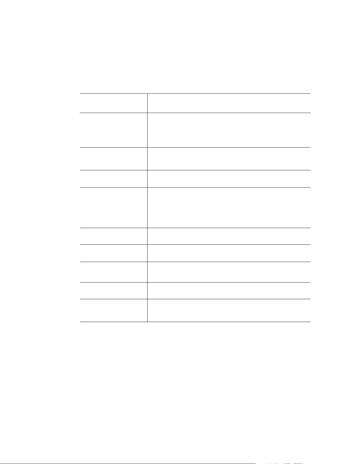
Figure 1. Intel
The sever supports two identical motherboards, left and right I/O boards. Two I/O boards
have the same function with different placement. Based on the Intel
platform, each server board uses high-performance, dual processors of the Intel
5500 Series and Intel
complicated server tasks. The following highlights are the main features of one server
board and one I/O board. For additional information, refer to this user manual.
Note: Except where indicated, all descriptions are based on one server board.
Note: The minimum configuration of the server system is to install the right server board. You
can only access the power supply when the right server board is installed. The
corresponding I/O board must be fixed to the server board when powering on the system.
®
Server System SR1680MV with 2.5-inch Pluggable HDDs
®
5500 chipset
®
ICH10R chipsets. Two server boards can accelerate even the most
®
Xeon®
Intel® Server System SR1680MV Service Guide 1
Page 24
Table 1 summarizes the features of the server chassis.
®
Table 1. Intel
Feature Description
Server System SR1680MV Feature Summary
Dimensions
• 43.2 mm height
• 448 mm width
• 714.2 mm depth
• Minimum weight: 11.7 kg
• Maximum weight: 17.16 kg
Processor
Memory • Three channels per processor; up to three DIMMs per channel
• Support for up to four Intel
per server node)
®
Xeon® Processor 5500 Series (two
• 72 GB maximum per processor (8 GB DIMM)
• Supports DDR3 speeds of 800/1066/1333 MHz
• Supports up to three registered DIMMs per channel; 8 GB
maximum per registered DIMM
• Supports up to two unbuffered DIMMs per channel; 4 GB
maximum per unbuffered DIMM
• Supports single-rank (SR), dual-rank (DR), and quad-rank
(QR) DIMM modules
On-board LAN • Dual Gigabit Ethernet ports
• Network controllers embedded in Intel
®
82576 chipsets
• Interface compatible with IEEE/ANSI 802.3
On-board VGA
• Server Engines* Pilot II
• One front VGA connector
Integrated Super I/O
• Keyboard Style/BT interface for BMC support
• Fully Functional Serial Port, compatible with the 16C550
• Supports Serial IRQ
• Supports SMI/SCI/PME
• Apply ACPI compliant
• Supports up to 32 shared GPIO ports
• Supports Programmable Wake-up Event
• Supports Plug and Play (PnP) Register Set
• Power Supply Control
• Watchdog timer compliant with Microsoft SHDG*
• Real-time Clock (RTC) with the external RTC interface
Riser and Expansion
Card
• One PCI-E x8 slot on each I/O board to support a 25-W
maximum PCI-E riser
• Supports a low-profile PCI-E expansion card on each riser
connector
2 Intel® Server System SR1680MV Service Guide
Page 25
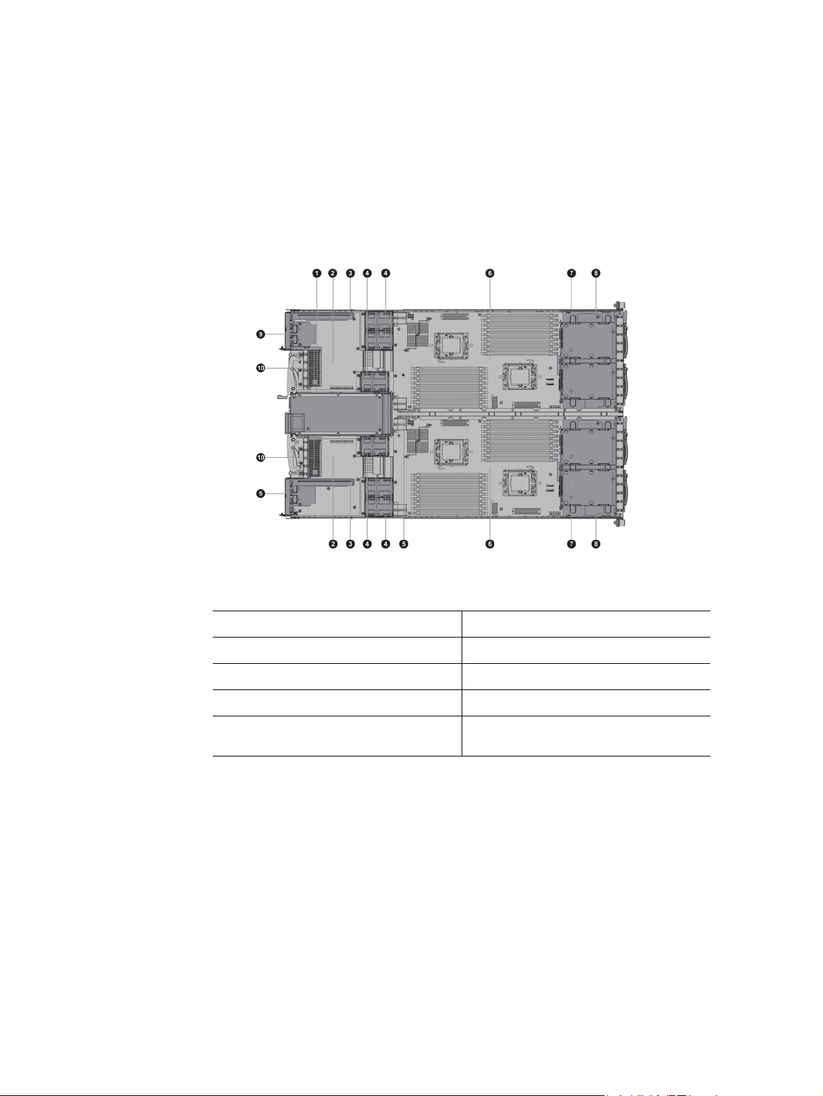
System Overview
Server Chassis Layout
1. Power Supply 6. Server boards
2. I/O Boards 7. Pluggable HDD Backplane
3. PCI-E Cage 8. Pluggable HDD Bays
4. System Fans 9. NIC Card
5. Power Distribution Board 10. GB I/O Card or InfiniBand* Card
Figure 2. Layout of Server Chassis with 2.5-inch Pluggable HDDs
Front View Components
The front view of this 1U server allows easy access to 2.5-inch pluggable SATA HDDs.
Some connectors, buttons, and system LEDs of both internal and external devices are
located on the front.
(optional)
Intel® Server System SR1680MV Service Guide 3
Page 26
The following introduces the front view of the server with 2.5-inch pluggable HDDs:
1. VGA Port 7. UID Button
2. Serial Port 8.UID LED
3. NIC LED 9. Power LED
4. Front Panel USB Port 10. Front Panel USB Port
5. System Health LED 11. HDD LED
6. Power Button 12. 2.5-inch Pluggable HDDs
Figure 3. Front View of Server with 2.5-inch Pluggable HDDs
Back View Components
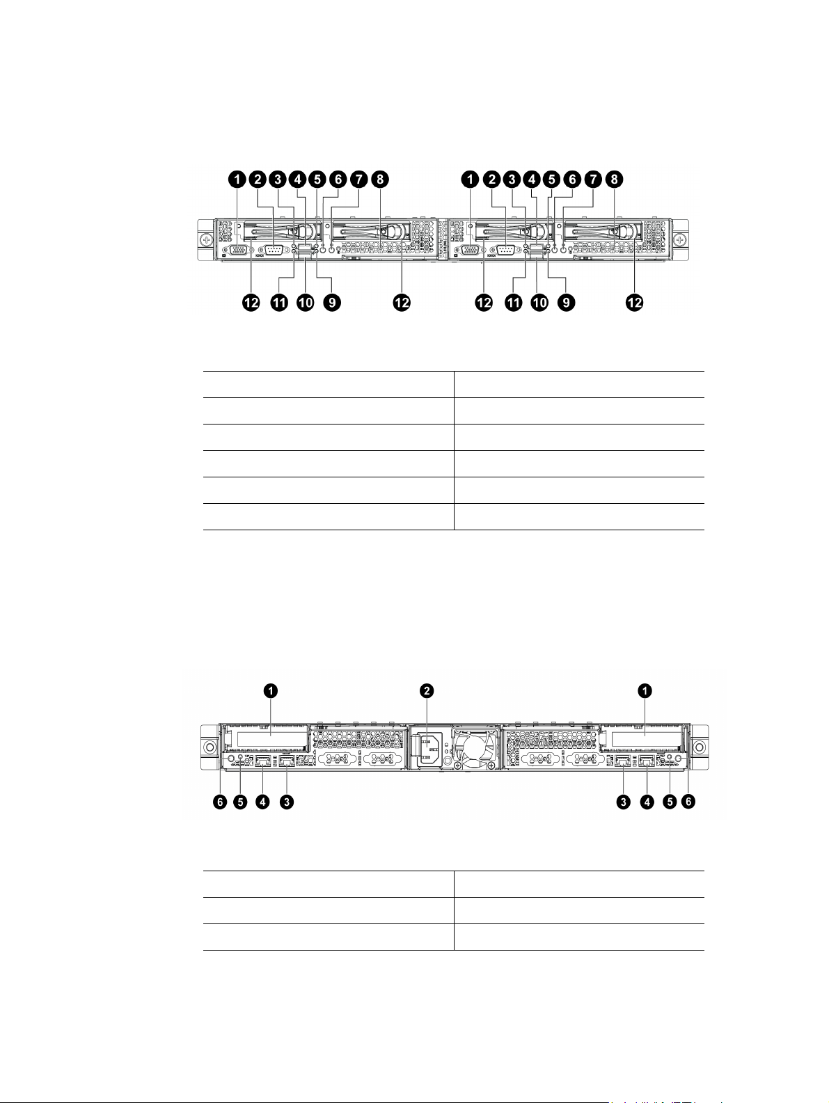
The server back view includes connectors, buttons, and system LEDs of both internal and
external devices.
1. PCI-E Cages 4. Rear NIC2 Ports
2. AC Power Outlet 5. Rear UID LEDs
3. Rear NIC1 Ports 6. Rear UID Buttons
Figure 4. Back View
4 Intel® Server System SR1680MV Service Guide
Page 27
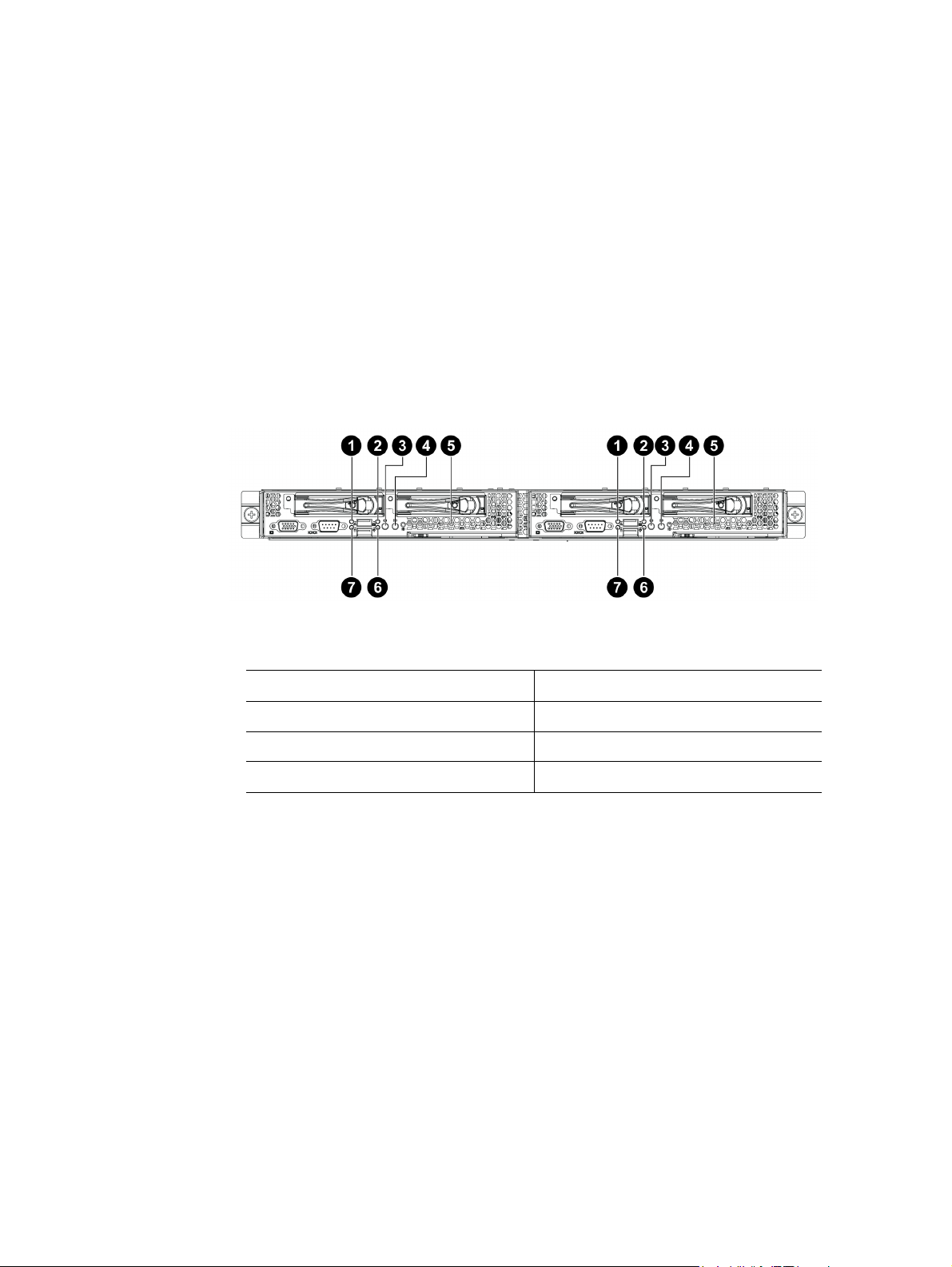
Buttons and System LEDs
Front Panel Buttons and LEDs
This server is equipped with system LED indicators, buttons, and two front panel USB
ports located on the front panel. The front panel status LEDs allow constant monitoring of
basic system functions while the server is operating. These LEDs provide visual cues to
the status of NIC link, system health, UID (unique identifier), and power.
The following figures shows the front panel:
1. NIC LED 5. UID LED
2. System Health LED 6. Power LED
3. Power Button 7. HDD LED
4. UID Button
Figure 5. Front Panel Buttons and LEDs of Server
Intel® Server System SR1680MV Service Guide 5
Page 28
The back view LEDs and buttons information display details regarding the LEDs and
buttons of the two I/O boards and AC power LED.
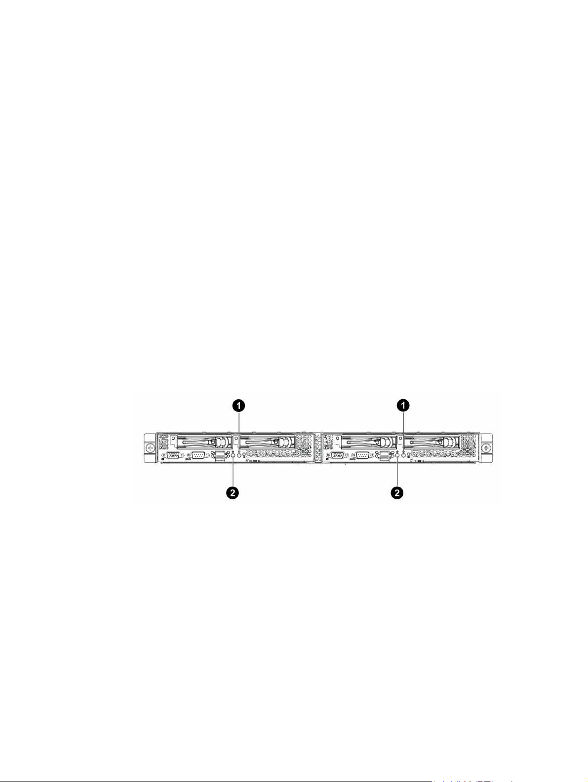
Rear Panel Button and LEDs
1. Rear UID Buttons 4. NIC 1&2 Link LEDs
2. Rear UID LEDs 5. AC Power LED
3. NIC 1&2 Activity LEDs
Figure 6. Back View LEDs and Buttons of Two I/O Boards
The following table provides detailed LED information.
LED Information
Table 2. LED Information
Feature Color Description
Front View LEDs
Power LED Amber On: System has AC power but in standby mode.
Green On: System has AC power and is turned on.
- Off: No AC power to the system.
6 Intel® Server System SR1680MV Service Guide
Page 29
Table 2. LED Informat i on
Feature Color Description
System Health LED Red Blinking: System has non-critical errors. After error
condition is cleared, LED is off.
On: System has critical errors. LED needs to remain
active until the next power-off and power-on provided
that the error condition is cleared.
- Off: System off / System OK.
HDD Activity LED Green Blinking: Drive activity
- Off: No drive activity
NIC 1&2 LED Green Blinking: Linked and activity on the network
On: Linked to network
- Off: LAN not connected
UID LED Blue Blinking: Command trigger
On: Identification
- Off: Disabled
Back View LEDs
NIC 0&1 Activity LED Green Blinking: Linked and activity on the network.
- Off: No connection
NIC 0&1 Link LED GREEN On: Linked to the network.
- Off: No connection
UID LED Blue Blinking: System is being remotely managed
On: Identification
- Off: Disabled
AC Power LED Green On: +12V is output
- Off: No AC on or no main power on
Intel® Server System SR1680MV Service Guide 7
Page 30

8 Intel® Server System SR1680MV Service Guide
Page 31

2 Hardware Installations and
Upgrades
Before You Begin
Before working with your server product, pay close attention to “Safety Information”.
This document provides instructions for adding and replacing system components. For
instructions on replacing components on the server board, such as the processor and
memory DIMMs, and PCI-E add-in cards.
In addition, this server is also designed with the tool-less feature, which permits to remove
or install the components without any tools. The locking tab, retaining clip and so forth
provide the convenient method to lock the components on the server chassis. The tool-less
components are listed:
• Motherboard Cage Modules
• I/O Board Cage Modules
• Power Supply Module
• Power Distribution Board
• System Fans
• Air Ducts
• System Battery
• PCI Cage
• 2.5-inch Pluggable SATA HDDs
Note: The components shown in this chapter are mainly for your reference. Please take the
actual shipment as standard.
Tools and Supplies Needed
• Phillips* (cross head) screwdriver (#1 bit and #2 bit)
• Needle nosed pliers
• Antistatic wrist strap and conductive foam pad (recommended)
Intel® Server System SR1680MV Service Guide 9
Page 32
System References
All references to left, right, front, top, and bottom assume the reader is facing the front of
the chassis as it would be positioned for normal operation.
Power Off
Before any replacement, you must power off the server completely. Complete the
following steps to power off the server completely.
Caution: To reduce the risk of injury from electric shock, remove the power cord to completely
disconnect power from the system.
Warning: Moving the Power On/Off switch to the Off position does not completely remove power
from the system. Some portions of the power supply and some internal circuitry remain
active. Disconnect all power cords from the server to completely remove power from the
system.
Pressing the Power Button
Press the power button (“1”) to toggle the serve to hibernation. The power LED (“2”) in
TBD turns off.
Figure 7. Pressing the Power Button
10 Intel® Server System SR1680MV Service Guide
Page 33
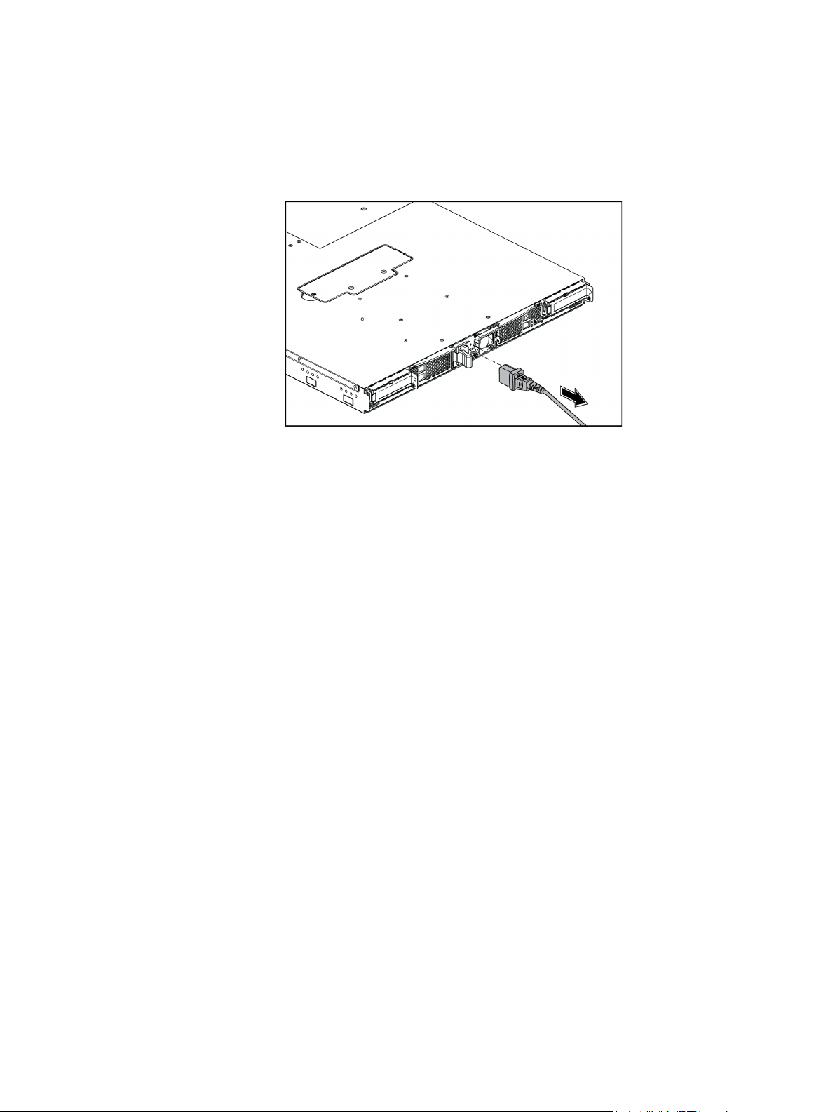
Unplugging the Power Cord
You must first unplug the power cord from the AC outlet and then from the server.
Mid-Top Cover
Figure 8. Unplugging the Power Cord
The server is a 1U form factor designed for easy assembly and disassembly, making the
replacement of internal components convenient.
Note: Before you remove or install the rear top cover, follow this step:
1. Make sure the server is not turned on or connected to the AC power. To power off
the server, see “Power Off”.
Removing the Mid-Top Cover
1. Release the screw on the mid-top cover.
2. Press down the locking button along the direction of the arrow.
3. Simultaneously slide the mid-top cover forward in the direction of the arrow using
the traction pad, and then lift it up.
Intel® Server System SR1680MV Service Guide 11
Page 34
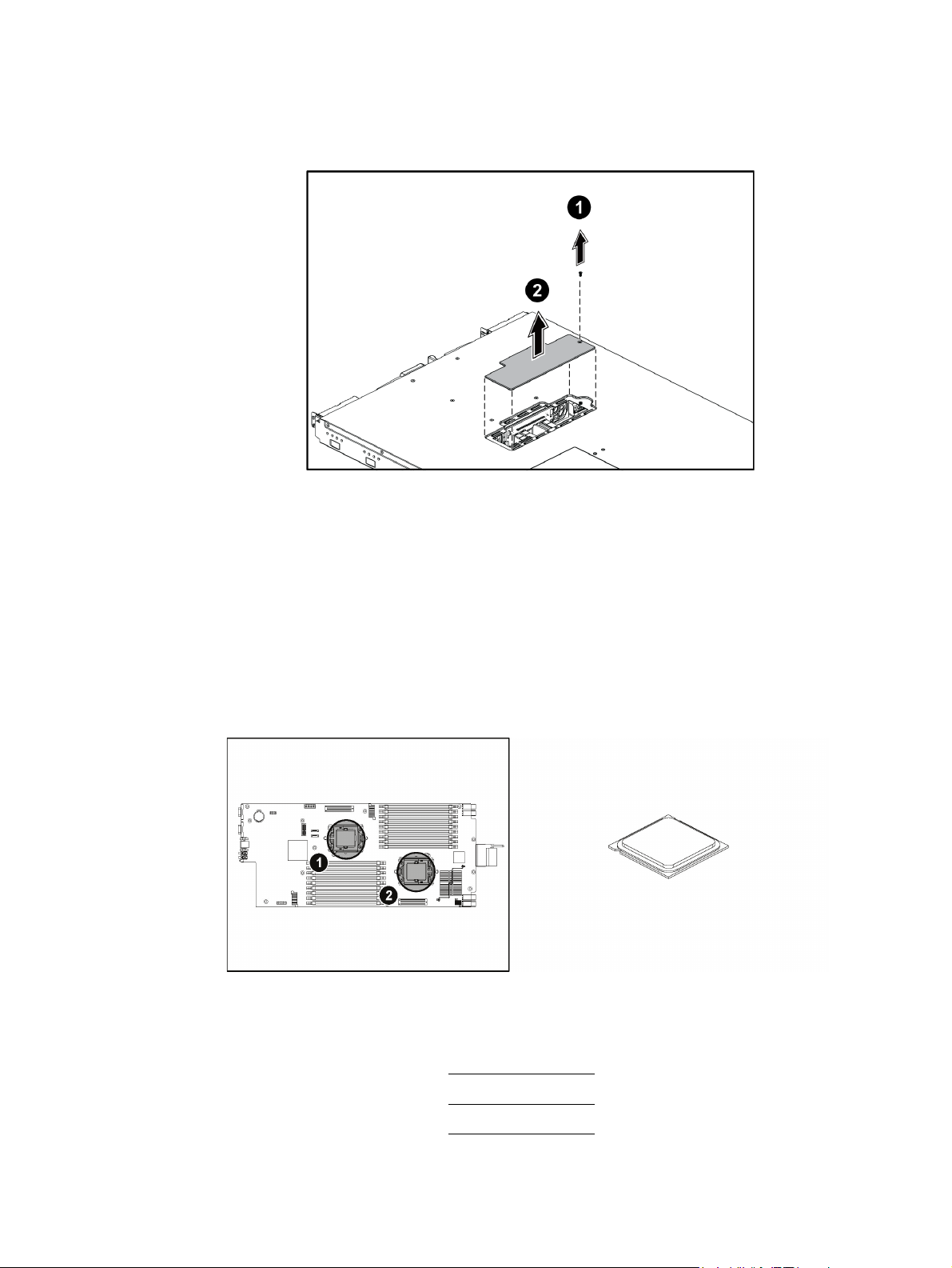
Figure 9. Removing the Mid-Top Cover
Central Processing Unit (CPU)
Each installed server node provides two surface mount LGA 1366 CPU sockets designed
for the Intel
®
Xeon® Processor 5500 series. One server node can be configured to either a
single- or dual-processor system.
The following figure shows the location of processors on the motherboard:
Figure 10. Location of Processors
1. Processor 1
2. Processor 2
12 Intel® Server System SR1680MV Service Guide
Page 35
You can install single or dual processors on the motherboard according to your own needs.
1. If a SINGLE processor is intended, it is recommended that you install the processor
on the processor 1 socket. Refer to Figure 10.
2. If installing DUAL processors, use the same type of processor running at the same
frequency.
Note: Before you remove or install the heatsink, processor or heatsink socket, complete the
following steps:
1. Make sure the server is not turned on or connected to the AC power. To power off
the server, see “Power Off”
2. Remove the chassis cover. To remove the cover, see “Mid-Top Cover”.
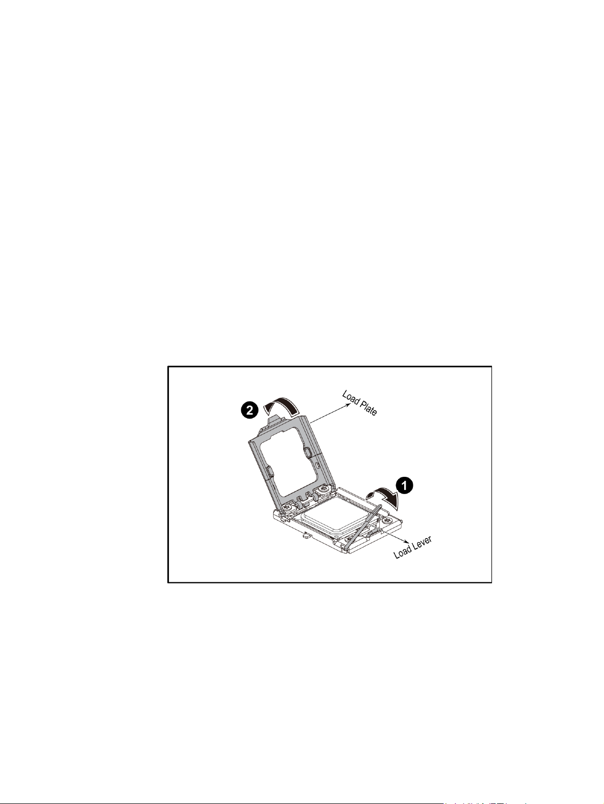
Removing the Processor
1. Unlock the load lever and lift it up.
2. Open the load plate.
Figure 11. Opening the Load Plate
3. Lift the processor out of the socket.
Intel® Server System SR1680MV Service Guide 13
Page 36
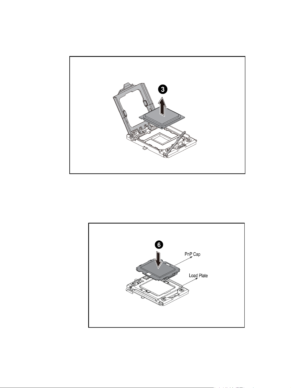
Figure 12. Lifting the Processor Out of the Socket
4. Place the PnP cap onto the load plate.
Figure 13. Placing on the PnP Cap
14 Intel® Server System SR1680MV Service Guide
Page 37
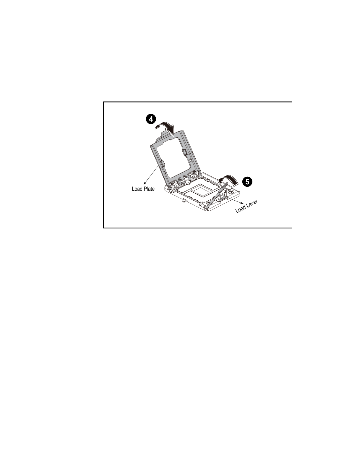
5. Close the load plate.
6. Lock the load lever.
Figure 14. Closing the Load Plate
Installing the Processor
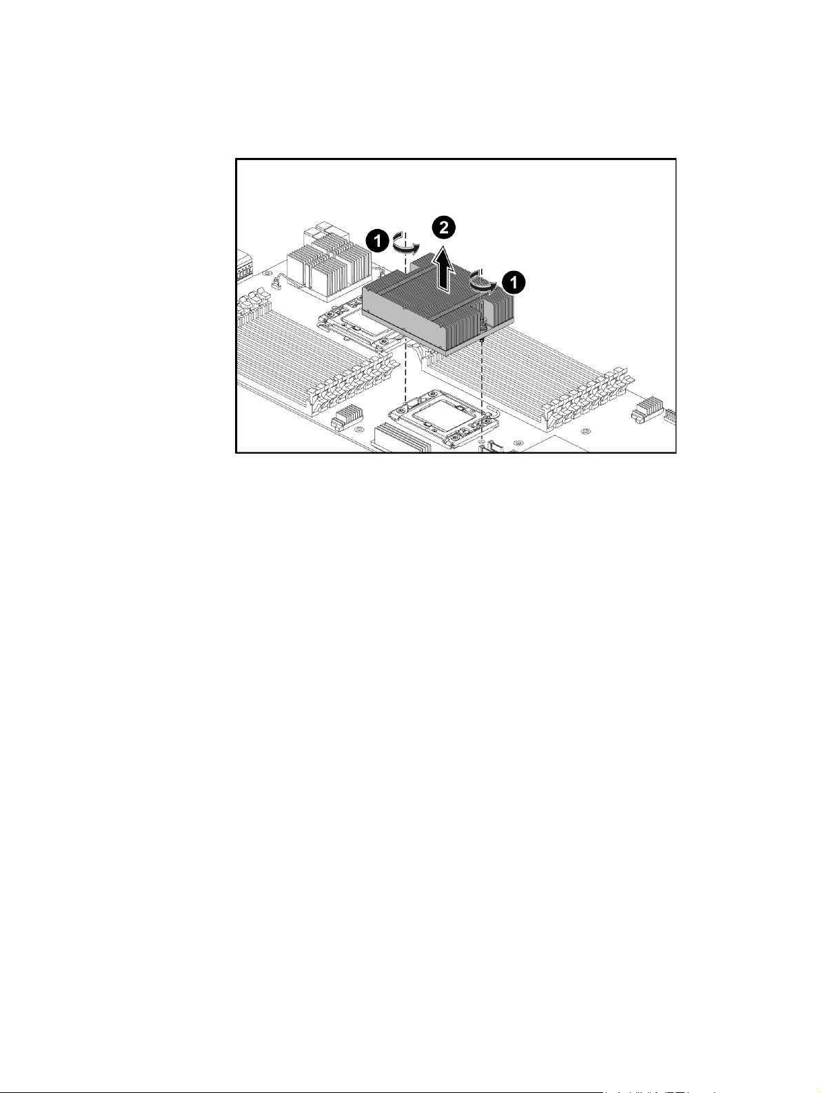
Reverse the steps in “Removing the Processor” to install the processor. However, when
inserting the processor into the socket, make sure the golden corner on the processor is
pointed toward the socket.
Intel® Server System SR1680MV Service Guide 15
Page 38
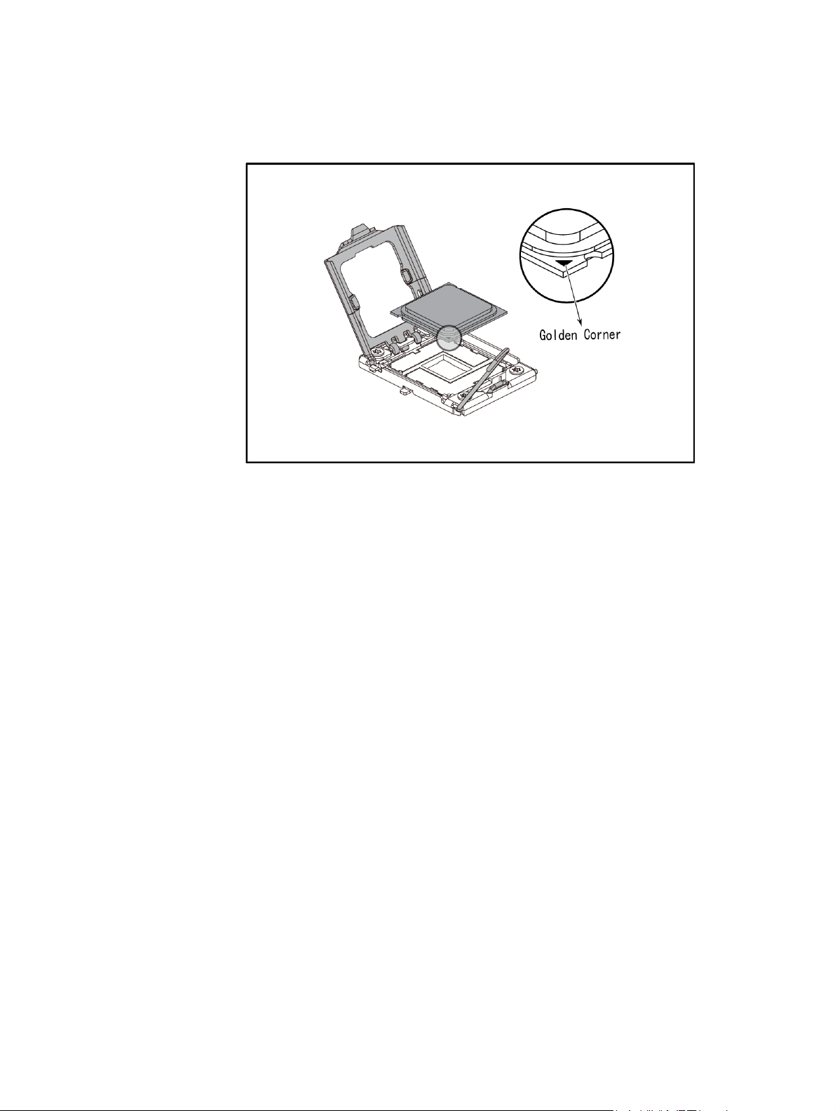
Figure 15. Pointing the Golden Corner Toward the Socket
Note: When the processor is in place, press it firmly on the socket while you push down the
socket lever to secure the processor. The lever clicks on the socket indicating it is locked.
The processor fits only in one orientation. Do not force the processor into the socket to
avoid bending the pins and damaging the processor. If the processor does not fit
completely, check its orientation or check for bent pins
Removing the Heatsink
1. Loosen the two securing screws.
2. Lift the heatsink up from the installed processor.
16 Intel® Server System SR1680MV Service Guide
Page 39
Installing the Heatsink
Reverse the steps in “Removing the Heatsink” to install the heatsink. Make sure you put
the heatsink in the right direction—you should see the heatsink information when you
finish the heatsink installation.
Note: Before you put the heatsink on top of the installed processor, do not forget to check if the
grease is completely on the bottom of the heatsink. Put the two heatsinks with the 16-fin
side facing the corresponding DIMM group.
System Memory
Each motherboard supports 18 DDR3 1333/1066/800 DIMMs depending on DIMM
population and each processor supports up to three channels, one channel with three slots.
Both registered DIMM and unbuffered DIMM modules are supported. One processor
supports up to 72GB memory when 8GB DIMM is available.
Mixed memory is neither tested nor supported. Non-ECC memory is not tested and is not
recommended for use in a server environment.
The location of DIMM sockets on the motherboard is shown in Figure 17:
Figure 16. Removing the Heatsink
Intel® Server System SR1680MV Service Guide 17
Page 40
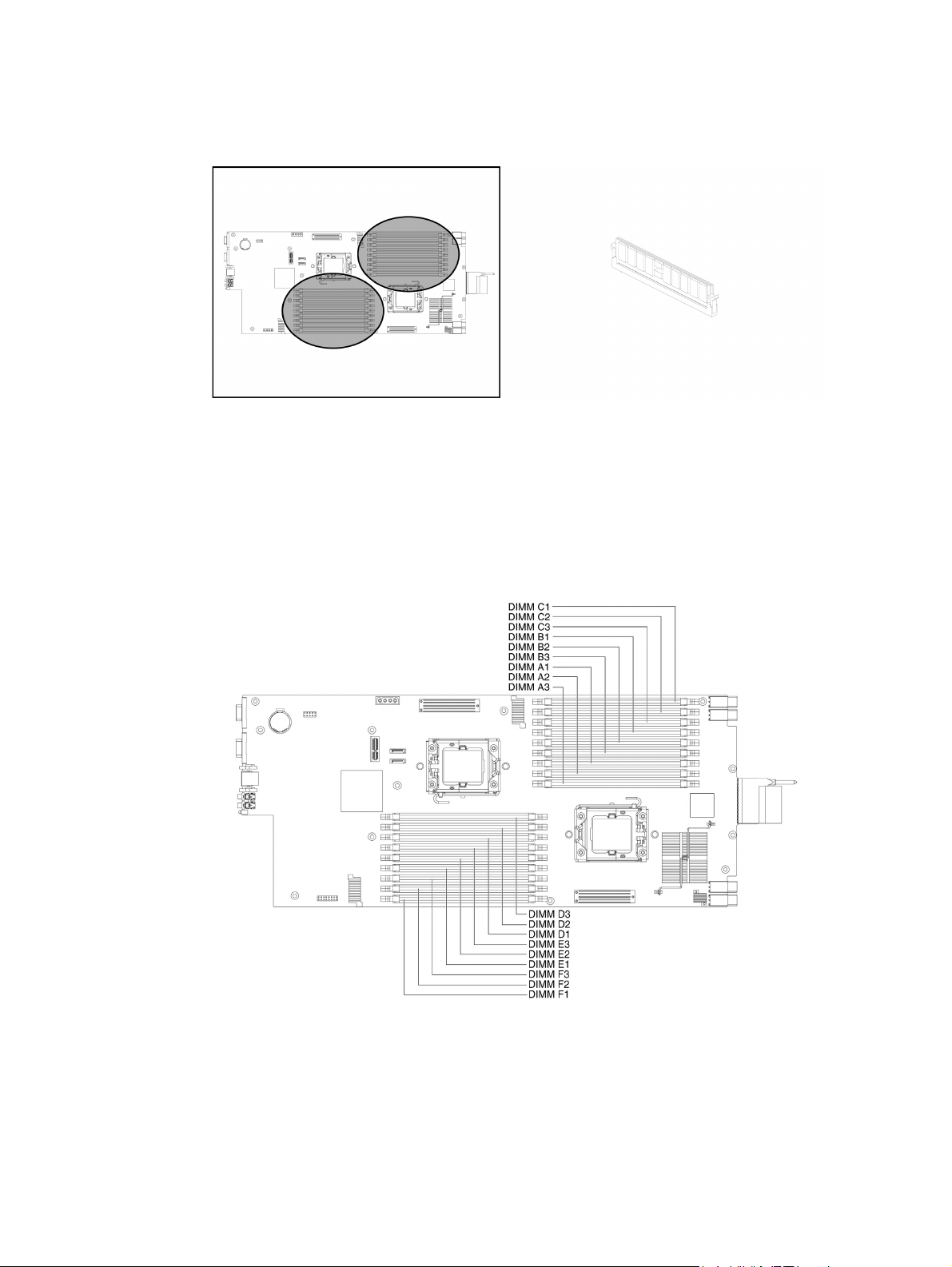
Figure 17. Location of System Memories
There are 18 DIMMs on the motherboard to support processor 1 and processor 2. The
DIMM sequence of 18 DIMM sockets is respectively shown in Figure 18.
Figure 18. DIMM Socket Location
18 Intel® Server System SR1680MV Service Guide
Page 41

System Memory Channel Population Requirements for Memory RAS Modes
The rules on channel population and channel matching vary by the RAS mode used. There
are three different memory RAS modes: Independent Channel Mode, Mirrored Channel
Mode, and Lockstep Channel Mode.
Note: Mirrored Channel Mode and Lockstep Channel Mode require matching populations that
the same slot positions across channels must hold the same DIMM type with regards to
size and organization.
Independent Channel Mode
Channels can be populated in any order in this mode. All these channels may be populated
in any order and have no matching requirements. All channels must run at the same
interface frequency but individual channels may run at different DIMM timings (RAS
latency, CAS latency, and so forth).
Mirrored Channel Mode
In Mirrored Channel Mode, the memory contents are mirrored between Channel 0 and
Channel 1. As a result of the mirroring, the total physical memory available to the system
is half of what is populated. Mirrored Channel Mode requires that Channel 0 and Channel
1 must be populated identically with regards to size and organization. DIMM slot
populations within a channel do not have to be identical but the same DIMM slot location
across Channel 0 and Channel 1 must be populated the same. Channel 2 is unused in
Mirrored Channel Mode.
Lockstep Channel Mode
In Lockstep Channel Mode, each memory access is a 128-bit data access that spans
Channel 0 and Channel 1. Lockstep Channel mode is the only RAS mode that supports x8
SDDC. Lockstep Channel Mode requires that Channel 0 and Channel 1 must be populated
identically with regards to size and organization. DIMM slot populations within a channel
do not have to be identical but the same DIMM slot location across Channel 0 and
Channel 1 must be populated the same. Channel 2 is unused in Lockstep Channel Mode.
For your reference, Table 3 offers an ideal DIMM population option for A-F channels of
processor 1 and 2. The last column in tables marks DIMM installation under Mirrored
Channel Mode for your reference.
Intel® Server System SR1680MV Service Guide 19
Page 42

Table 3. Ideal DIMM Installation Options for A-C Channels of Processor 1
DIMM A3 A2 A1 B3 B2 B1 C3 C2 C1
1--V-- - -
2--V--V- -
3--V--V- - V
4-VV- V- V
5-VV-VV- V
6-VV-VV- V V
7VVV VV V V
8VVVVVV V V
9VVVVVVV V V
Table 4. Ideal DIMM Installation Options for D-F Channels of Processor 2
DIMM D3 D2 D1 E3 E2 E1 CF F2 F1
1--V-- - -
2--V--V- -
3--V--V- - V
4-VV- V- V
5-VV-VV- V
6-VV-VV- V V
7VVV VV V V
8VVVVVV V V
9VVVVVVV V V
Note: The empty DIMM socket is marked as “-” and installed DIMM socket is marked as “V”.
It is recommended to insert DIMM equally for each CPU so as to give maximizes system
performance.
It is highly recommended that all DIMMs with same part number be used within one
motherboard.
For Unbuffered DIMMs or Quad-rank Registered DIMMs, only configuration 1~6 could
be supported.
Optional Note: For other Registered DIMMs, configuration 1~9 could be supported.
20 Intel® Server System SR1680MV Service Guide
Page 43

Before you remove or install any DIMMs, complete the following steps:
1. Make sure the server is not turned on or connected to the AC power. To power off
the server, see “Power Off”.
2. Remove the chassis cover. To remove the cover, see “Mid-Top Cover”.
Removing a DIMM
1. Unlock a DIMM socket by pressing the retaining clips outward. This action
releases the module and partially lifts it out of the socket.
2. Lift out the DIMM.
Figure 19. Lifting the DIMM Out of the Socket
Installing a DIMM
1. Unlock a DIMM socket by pressing the retaining clips outward.
Intel® Server System SR1680MV Service Guide 21
Page 44

Figure 20. Pressing the Retaining Clips Outward
2. Align the notch on the DIMM to the break on the socket. Carefully insert the
DIMM into the socket until the retaining clips snap back in place.
Figure 21. Inserting the DIMM into the Socket
22 Intel® Server System SR1680MV Service Guide
Page 45

Note: DIMMs fit in only one direction. DO NOT force a DIMM into the socket to avoid
damaging the DIMM.
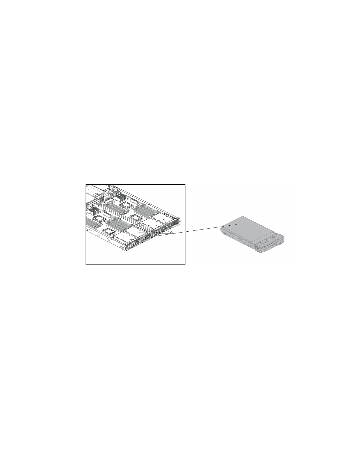
Server Board Cage Module
This section explains how to replace the server board cage module from the chassis.
Figure 22. Server Board Cage Module with 2.5-inch Pluggable SATA HDD Location
Warning: When installing the server board cage module, make sure that you place it into the chassis
correctly. The edge with the external ports goes to the back panel of the chassis.
When handling the server board cage module, avoid touching any metal leads or
connectors.
Removing the Server Board Cage Module
1. Slide the locking latch along the direction of the arrow.
2. The cage locking lever springs open by itself.
Figure 23. Releasing the Locking Latch
Intel® Server System SR1680MV Service Guide 23
Page 46

3. Pull the cage tray lever along the direction of the arrow to remove the module.
Figure 24. Pull the Locking Lever to Remove the Server Board Cage Module
Installing the Server Board Cage Module
Reverse the “Removing the Server Board Cage Module” steps to install the server board
cage module.
24 Intel® Server System SR1680MV Service Guide
Page 47

Left and Right I/O Board Cage Modules
The left and right I/O board cage modules share the same steps during the removal and
installation procedures. For your reference, this section takes the steps of removing and
installing the left I/O board cage module as an example.
The location of the left and right I/O board cage modules on the server chassis is shown in
the following figures:
Figure 25. Left I/O Board Cage Module Location
Figure 26. Right I/O Board Cage Module Location
Note: Before you remove or install the server board, complete these steps:
1. Make sure the server is not turned on or connected to the AC power. To power off
the server, see “Power Off”.
2. Disconnect all necessary cable connections.
3. When removing and installing I/O board cage module, keep the handle of the
power supply in the horizontal direction to avoid damage on it.
Intel® Server System SR1680MV Service Guide 25
Page 48

Removing the Left I/O Board Cage Module
1. Slide the locking latch along the direction of the arrow.
2. The cage tray lever springs open by itself.
Figure 27. Slide the Locking Latch
3. Pull the cage tray lever along the direction of the arrow to remove the module.
Figure 28. Pull the Locking Lever to Remove the Left I/O Board Cage Module
Installing the Left I/O Board Cage Module
Reverse the above steps to install the left I/O board cage module.
26 Intel® Server System SR1680MV Service Guide
Page 49
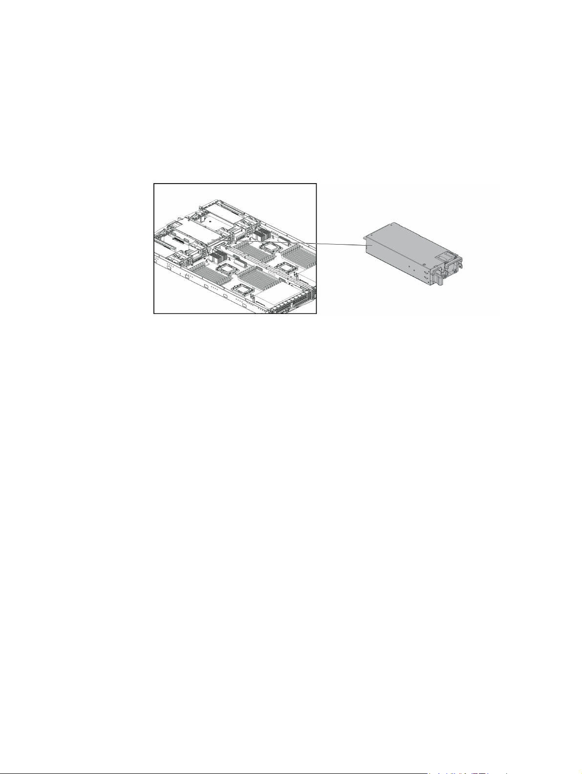
Power Supply Module
This section introduces the replacement procedure for the power supply module. The
following figure shows the location of power supply module on the server chassis:
Note: Before you remove or install the power supply, complete the following steps:
1. Make sure the server is not turned on or connected to the AC power. To power off
the server, see “Power Off”.
Figure 29. Power Supply Location
2. Disconnect all necessary cable connections.
Removing the Power Supply Module
1. Pull down the power supply handle in the horizontal direction.
2. Press the retaining clip on the left side of the power supply along the direction of
the arrow.
3. Simultaneously pull out the power supply by using its handle. (The power supply
takes considerable force to remove.)
Intel® Server System SR1680MV Service Guide 27
Page 50
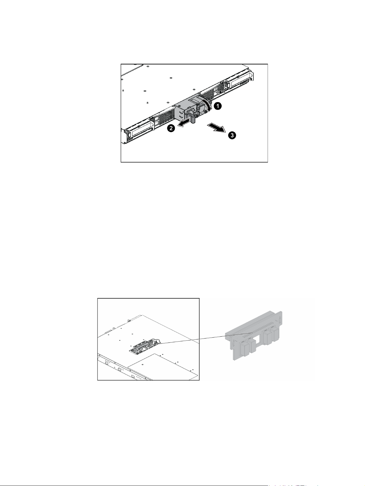
Figure 30. Removing the Power Supply Module
Installing the Power Supply Module
Reverse the “Removing the Power Supply Module” steps to install the power supply
module.
Power Distribution Board
This section introduces the replacement procedures of the power distribution board.
Figure 31 shows the location of the power distribution board on the server chassis.
Figure 31. Power Distribution Board
Note: Before you remove or install the power distribution board, complete the following steps:
1. Make sure the server is not turned on or connected to the AC power. To power off
the server, see “Power Off”.
28 Intel® Server System SR1680MV Service Guide
Page 51
2. Remove the mid-top cover. To remove the cover, see “Mid-Top Cover”.
3. Disconnect all necessary cable connections.
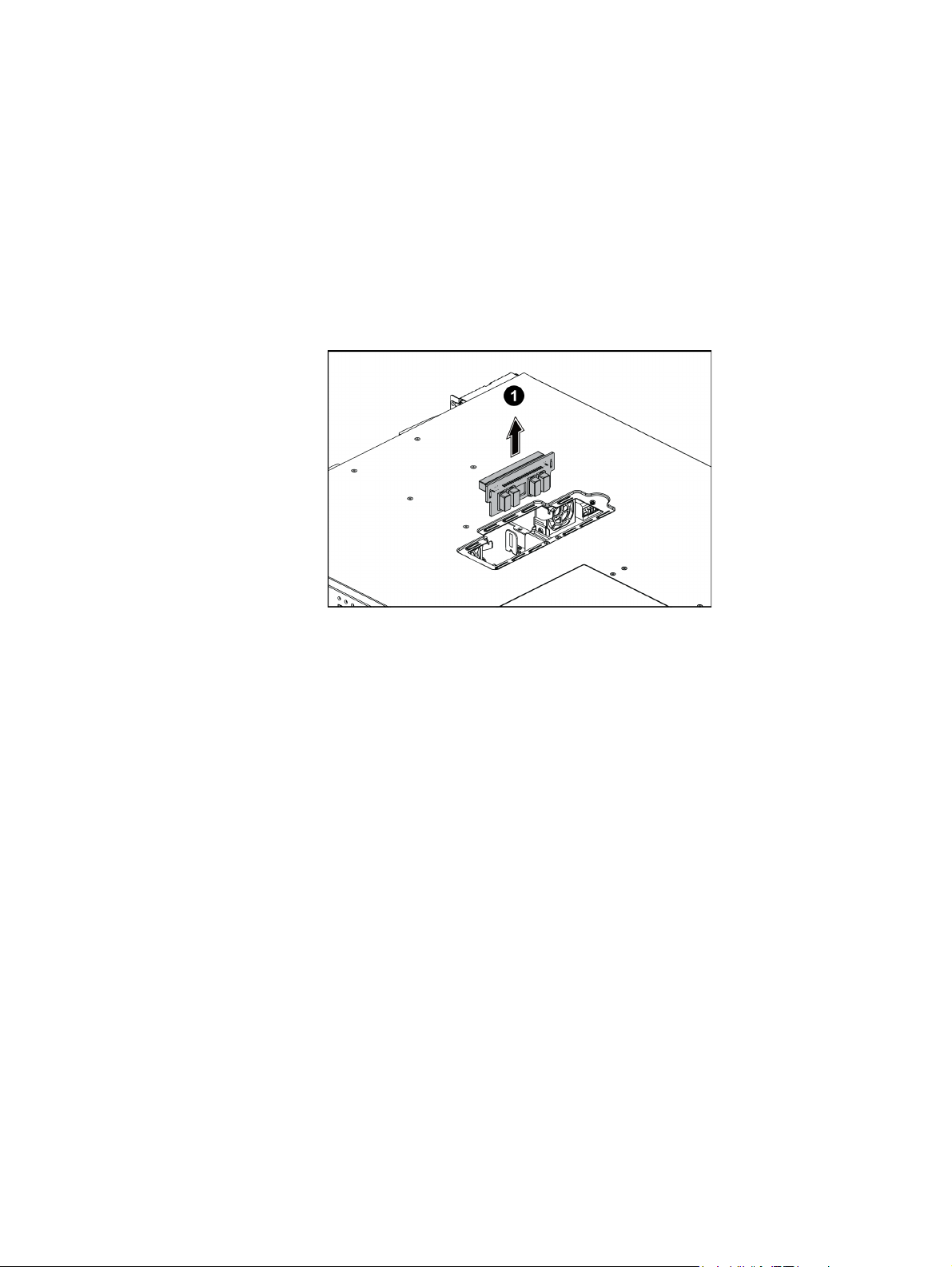
Removing the Power Distribution Board
1. Lift the power distribution board from the chassis.
Figure 32. Removing the Power Distribution Board
Installing the Power Distribution Board
Reverse the “Removing the Power Distribution Board” steps to install the power
distribution board.
Intel® Server System SR1680MV Service Guide 29
Page 52
Pluggable SATA Drive
2.5-inch Pluggable SATA HDD
The sever supports up to four 2.5-inch pluggable SATA HDDs, two on each server board
module. Four HDDs share the same removal and installation procedure. For your
reference, this section provides the steps of removing and installing one 2.5-inch
pluggable SATA HDD as an example.
Figure 33 shows the location of the 2.5-inch pluggable SATA HDD on the server chassis:
Figure 33. 2.5-inch Pluggable SATA HDD Location
Note: Before you remove or install the pluggable HDD, complete the following steps:
1. Make sure the server is not turned on or connected to the AC power. To power off
the server, see “Power Off”.
2. Disconnect all necessary cable connections.
3. Remove the HDD blank if the HDD blank is installed.
Removing a 2.5-inch Pluggable SATA HDD
1. Turn the lock counter-clockwise.
2. Slide the locking latch along the direction of the arrow.
3. The HDD carrier locking lever springs open by itself.
30 Intel® Server System SR1680MV Service Guide
Page 53
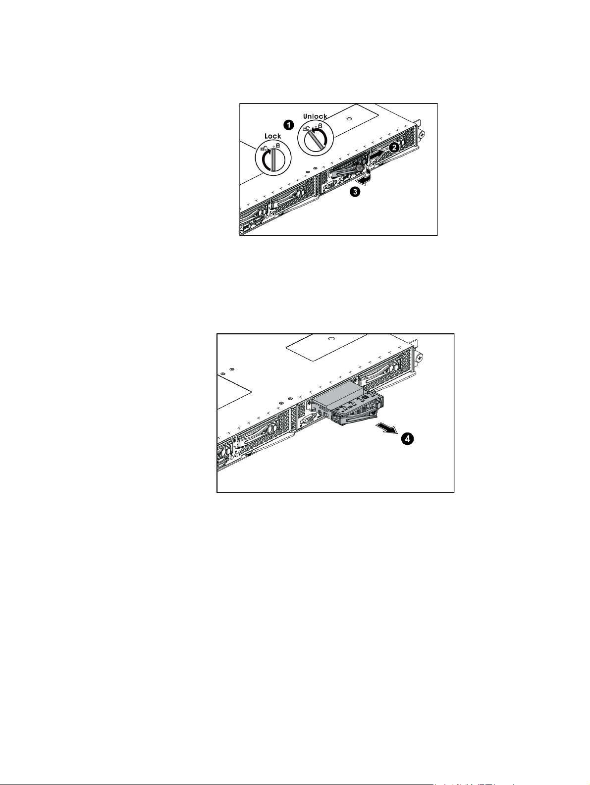
Figure 34. Release the Locking Lever
4. Pull the HDD carrier locking lever out along the direction of the arrow.
Figure 35. Pull the Locking Lever to Remove the HDD Carrier
5. Loosen and remove the four securing screws.
6. Lift the HDD up from the HDD carrier.
Intel® Server System SR1680MV Service Guide 31
Page 54
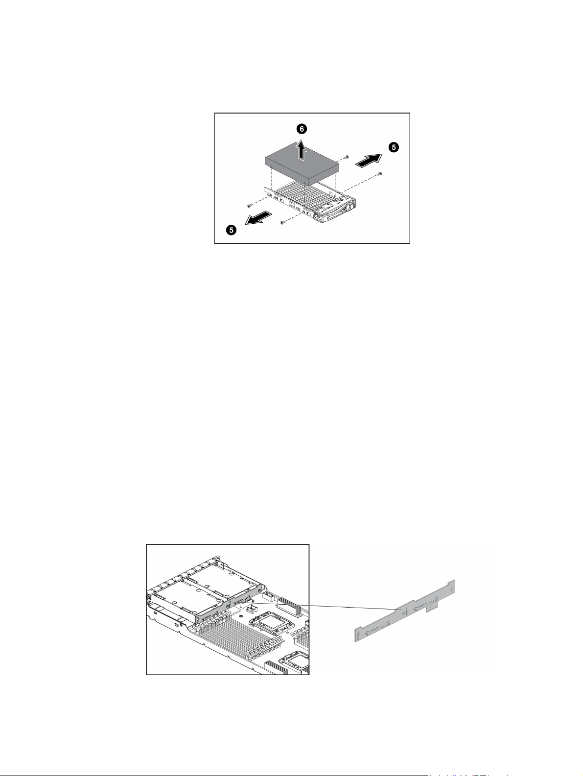
Figure 36. Release Screws and Lift the HDD Up
Installing a 2.5-inch Pluggable SATA HDD
Reverse the “Removing a 2.5-inch Pluggable SATA HDD” steps to install the 2.5-inch
pluggable SATA HDD.
2.5-inch Pluggable HDD Backplane
Each server board module supports one 2.5-inch pluggable HDD backplane; two HDD
backplanes share the same removal and installation procedure. For your reference, this
section provides the steps of removing and installing one 2.5-inch pluggable HDD
backplane as an example.
Figure 37 shows the location of a 2.5-inch pluggable HDD backplane on the server
chassis:
Figure 37. 2.5-inch Pluggable HDD Backplane Location
32 Intel® Server System SR1680MV Service Guide
Page 55

Note: Before you remove or install the power supply, complete the following steps:
1. Make sure the server is not turned on or connected to the AC power. To power off
the server, see “Power Off”.
2. Remove the motherboard cage module. To remove the cover, see “Removing the
Server Board Cage Module”.
3. Disconnect all necessary cable connections.
Removing an HDD Backplane
1. Loosen the two securing screws on the backplane.
2. Lift the backplane up from motherboard.
Figure 38. Remove the Screws and Lift the Backplane Up
Installing a 2.5-inch Pluggable SATA HDD Backplane
Reverse the “Removing an HDD Backplane” steps to install the 2.5-inch pluggable SATA
HDD backplane.
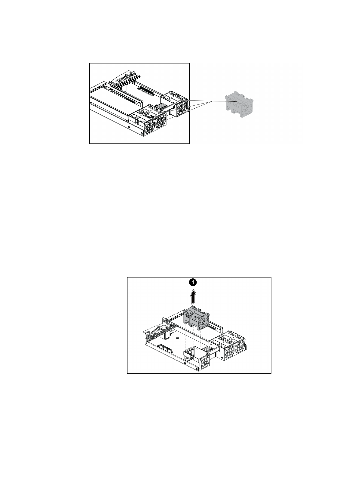
System Fans
Each I/O board cage module includes three system fans. The six system fans on the server
system share the same removal and installation procedures. For your reference, this
section provides the steps for replacing one system fan on the right I/O board cage module
as an example.
The following figure shows the location of the system fan on the right I/O board cage
module:
Intel® Server System SR1680MV Service Guide 33
Page 56
Note: Before you remove or install the power supply, complete the following steps:
1. Make sure the server is not turned on or connected to the AC power. To power off
the server, see “Power Off”.
2. Remove the left and right I/O board cage modules. To remove the cover, see “Left
and Right I/O Board Cage Modules”.
3. Disconnect all necessary cable connections.
Removing a System Fan
1. Lift the system fan up from the I/O board cage module.
Figure 39. System Fans Location
Figure 40. Lift a System Fan Up from I/O Board Cage Module
34 Intel® Server System SR1680MV Service Guide
Page 57
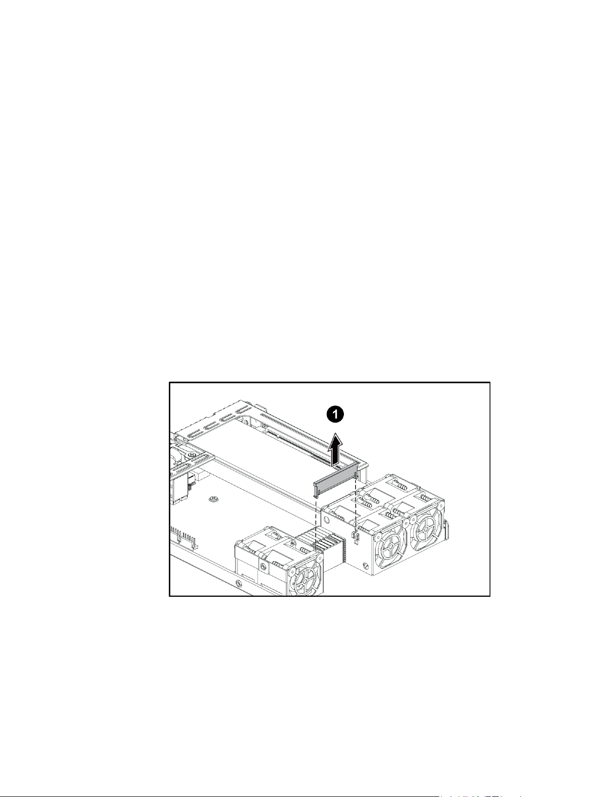
Installing a System Fan
Reverse the “Removing a System Fan” steps to install the system fan.
Air Duct
Note: Before you remove or install the air duct, complete the following steps:
1. Make sure the server is not turned on or connected to the AC power. To power off
the server, see “Power Off”.
2. Remove the left and right IO board cage modules. To remove the cover, see “Left
and Right I/O Board Cage Modules”.
3. Disconnect all necessary cable connections.
Removing the IOB Air Duct
1. Lift the air duct up from the I/O board cage module.
Figure 41. Lift Air Duct Up
Figure 41 shows the air duct located on I/O board.
Intel® Server System SR1680MV Service Guide 35
Page 58

Installing Air Ducts
Reverse the “Removing the IOB Air Duct” steps to install the air duct.
PCI-E Cage
The left and right I/O board cage modules each include one PCI-E cage. Two PCI-E cages
on the server share the same removal and installation procedures. For your reference, this
section provides the steps of removing and installing one PCI-E cage on the right I/O
board cage module as an example.
Figure 42 shows the location of the PCI-E cage on the right I/O board cage module:
Note: Before you remove or install the PCI-E cage, complete the following steps:
1. Make sure the server is not turned on or connected to the AC power. To power off
the server, see “Power Off”.
2. Remove the left and right I/O board cage modules. To remove the cover, see “Left
and Right I/O Board Cage Modules”.
3. Disconnect all necessary cable connections.
Removing a PCI-E Cage
1. Lift the PCI cage up from the I/O board cage module along the direction of the
arrow.
Figure 42. PCI-E Cage Location
36 Intel® Server System SR1680MV Service Guide
Page 59

Figure 43. Lifting the PCI Cage from the I/O Board Module
2. Loosen and remove the securing screw.
3. Pull out the expansion card with the slot cover from the PCI-E cage.
Figure 44. Removing the Expansion Card
4. Insert the slot cover to the right position along the arrow.
5. Secure the slot cover to the PCI-E cage with one screw as shown in Figure 45.
Intel® Server System SR1680MV Service Guide 37
Page 60

6. Loosen and remove the two securing screws as shown in Figure 46.
7. Pull the riser card out from the PCI-E cage along the direction of the arrow.
Installing a PCI-E Cage
Figure 45. Securing the Slot Cover
Figure 46. Removing the Riser Card
Reverse the “Removing a PCI-E Cage” steps to install the PCI-E cage.
Daughter Cards (Optional)
There are two optional daughter cards supported by each IO board. The 10 GB IO card
and the InfiniBand card share the same removal and installation procedure. For your
reference, this section takes the steps of removing and installing 10GB IO card as
example.
Figure 47 shows the location of the 10 GB IO card.
38 Intel® Server System SR1680MV Service Guide
Page 61

Figure 47. 10 GB IO Card Location
Figure 48 shows the location of the InfiniBand card.
Figure 48. InfiniBand Card Location
Note: Before you remove or install the 10 GB IO card, complete the following steps:
1. Make sure the server is not turned on or connected to the AC power. To power off
the server, see “Power Off”.
2. Remove the left and right IO board cage modules. To remove the cover, see “Left
and Right I/O Board Cage Modules”.
3. Disconnect all necessary cable connections.
Removing the IO Expansion Module
1. Separate guide pins of the module from the holes on the IO Board and lift the
module upward.
Intel® Server System SR1680MV Service Guide 39
Page 62

Figure 49. Lifting the Module Upward from the IO Board
2. Remove the I/O Expansion module out of the IO board module.
Figure 50. Removing the Module Upward from the IO Board
40 Intel® Server System SR1680MV Service Guide
Page 63

Installing the IO Expansion Module
Reverse the steps in the “Removing the IO Expansion Module”to install the IO Expansion
module.
Intel® Server System SR1680MV Service Guide 41
Page 64

42 Intel® Server System SR1680MV Service Guide
Page 65
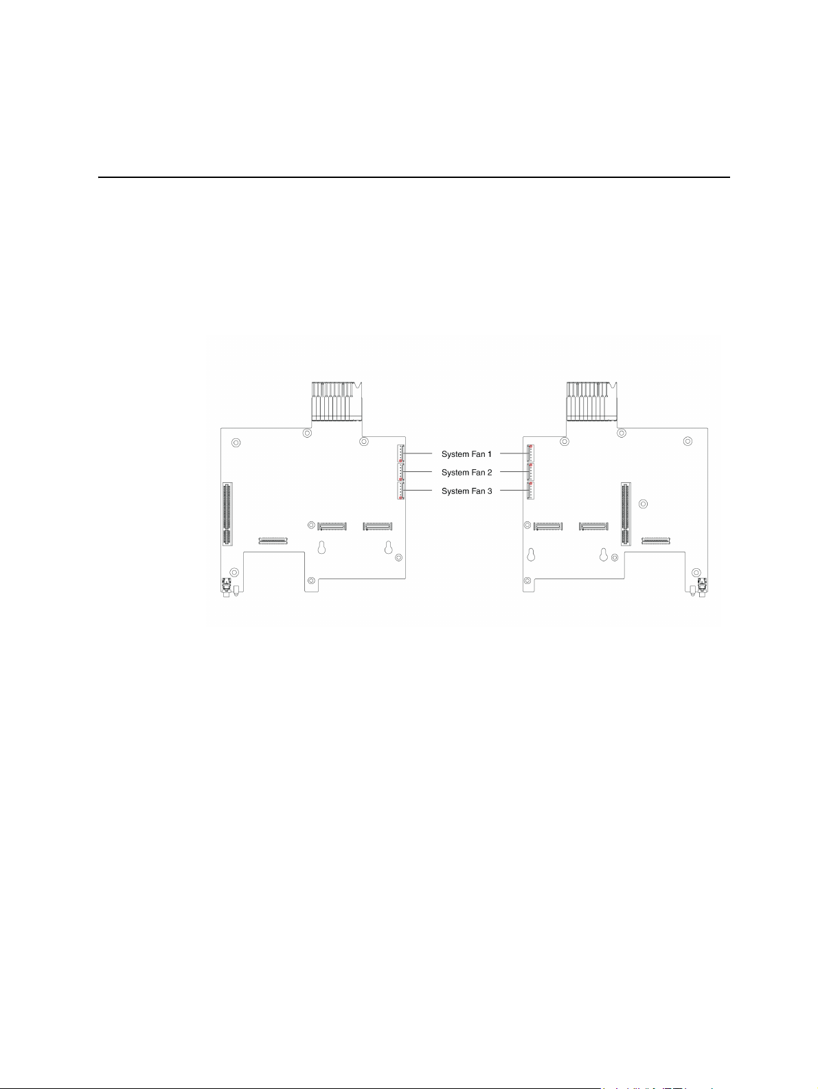
3 Cable Connections
Connectors and Pin 1 Locations
Figure 51 shows the different locations of the connectors and their pin 1 locations, which
can help you connect the cables.
Figure 51. Locations of Connectors and Pin 1 on Server Board
Intel® Server System SR1680MV Service Guide 43
Page 66

Cable Connections
You can get a clear picture on how to connect the cables from the following figures.
Before connecting the cables, you must make sure there are no existing bent pins because
they will affect signal transmission. With the Pin 1 location and fool-proof feature, you
can link these cables correctly and conveniently. There are two ways for you to judge how
to connect the cables:
1. When there is no fool-proof feature on this connector, you should connect the red
margin of the cable to the pin 1 location on the connector.
2. When there is a fool-proof feature on the connector, you can connect the cable
according to the fool-proof feature.
This section contains figures showing cable locations and descriptions of the connection
procedures.
System Fan Cables
System Fan Cables
Figure 52. Locations of Connectors and Pin 1 on I/O Board
Connect the 6-pin system fan cables from the system fans to the corresponding system fan
connectors on the I/O board.
44 Intel® Server System SR1680MV Service Guide
Page 67
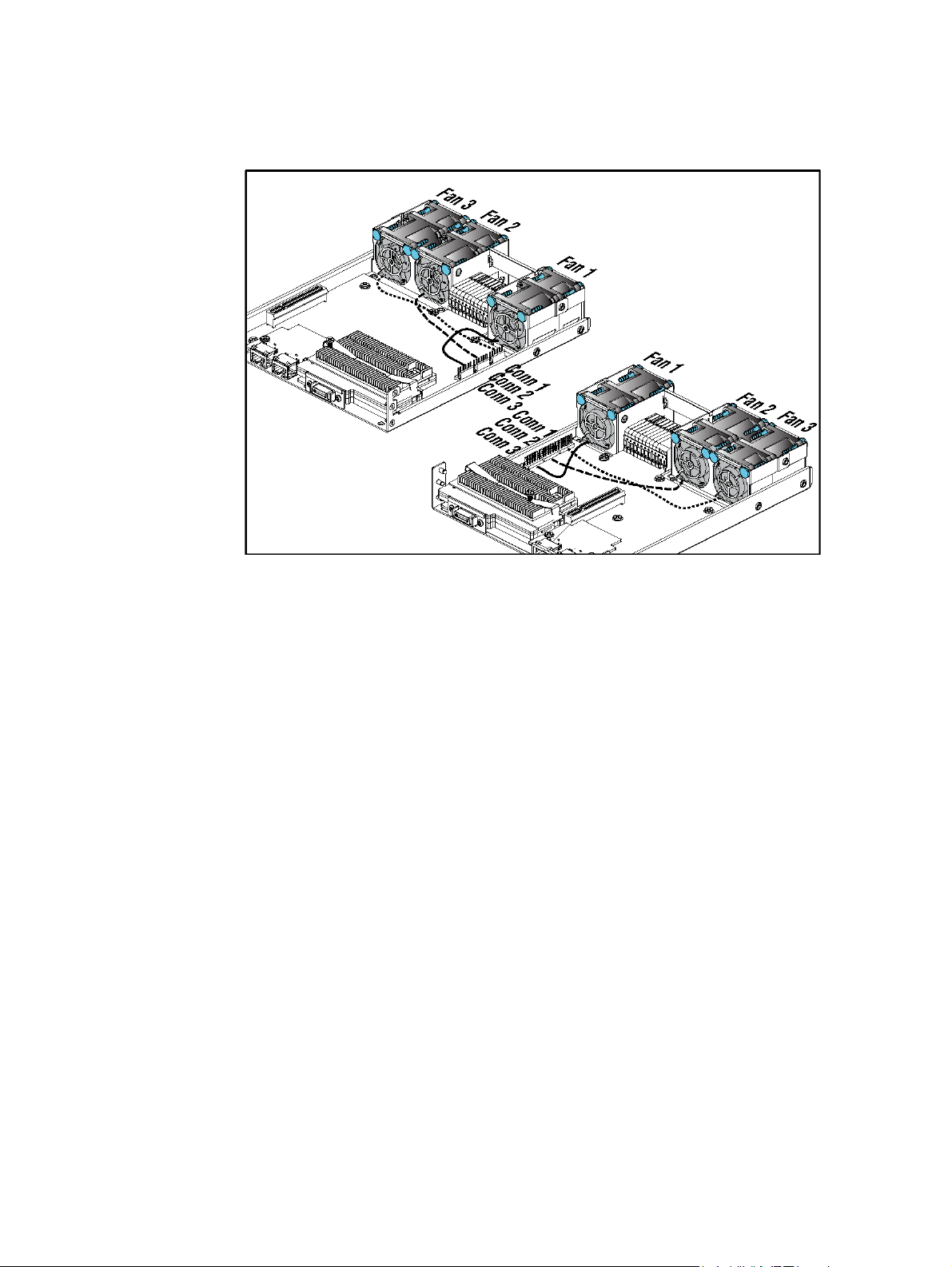
Figure 53. Connecting the System Fan Cables
Intel® Server System SR1680MV Service Guide 45
Page 68

46 Intel® Server System SR1680MV Service Guide
Page 69
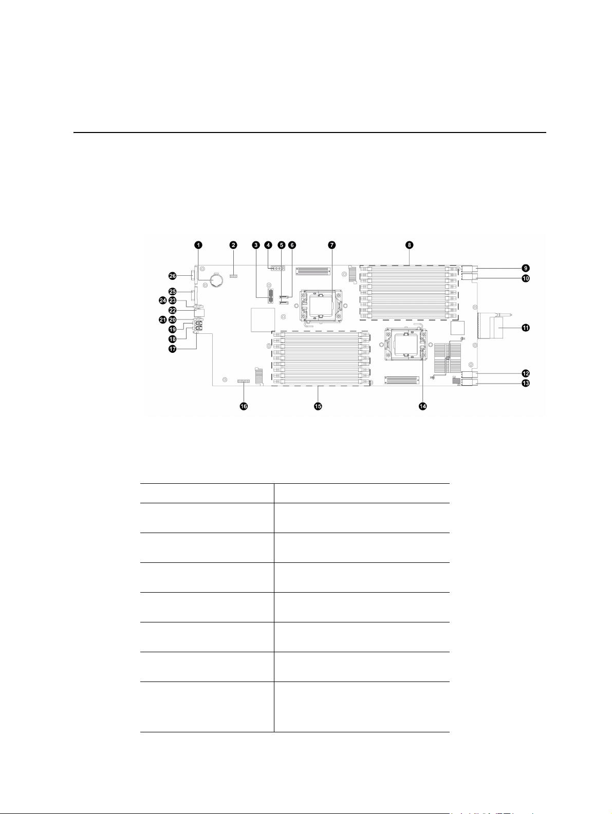
4 Connectors, Jumpers, and LEDs
Connector and Component Locations of Server Board
Figure 54. Connectors and Component Locations of Server Board
1. System Battery (BH1) 2. ICH Functions Jumper (J30)
3. HDD Backplane
Connector
5. Server board SATA4
Connector (J29)
7. Processor 1 (CPU 1) 8. DIMM Socket Group (J7, J8, J9,
9. Server board Power
Connector4 (J5)
11. Server board IO
Connector (J1)
13. Server board Power
Connector1 (J2)
15. DIMM Socket Group 2
(J17, J18, J19, J20,
J21, J22, J23, J24,
J25)
4. SATA Power Connector (J47)
6. Server board SATA3 Connector
(J31)
J10, J11, J12, J13, J14, J15)
10. Server board Power Connector3
(J4)
12. Server board Power Connector2
(J3)
14. Processor 2 (CPU 2)
16. MISC Jumper
Intel® Server System SR1680MV Service Guide 47
Page 70

17. Front UID LED 18. Front UID Button
19. Power Button 20. System Health LED
21. Power LED 22. Front USB Ports
23. NIC LED 24. HDD LED
25. Serial Port 26. VGA Port
48 Intel® Server System SR1680MV Service Guide
Page 71
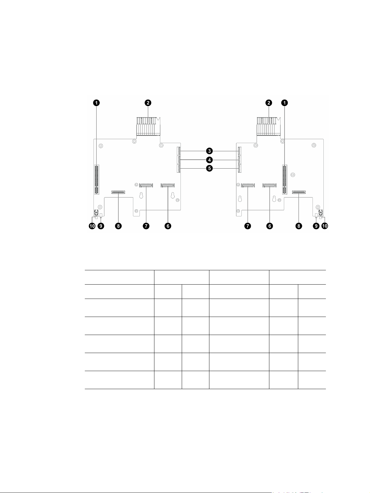
Connector and Component Locations of IO Board
Figure 55. Connectors and Component Locations of IO Boards
Description Location Description Location
Left Right Left Right
1. PCI-E x8 Slots J5 J5 2. IO Board IO
3. System Fan1
Connectors
5. System Fan3
Connectors
7. PCI-E 1
Connectors
9. Rear UID LEDs CR6 CR6 10. Rear UID
J6 J7 4. System Fan2
J7 J8 6. PCI-E 2
J3 J3 8. IO Board NIC
Connector
Connectors
Connectors
Connectors
Buttons
J10 J10
J8 J9
J2 J2
J4 J4
SW2 SW2
Intel® Server System SR1680MV Service Guide 49
Page 72
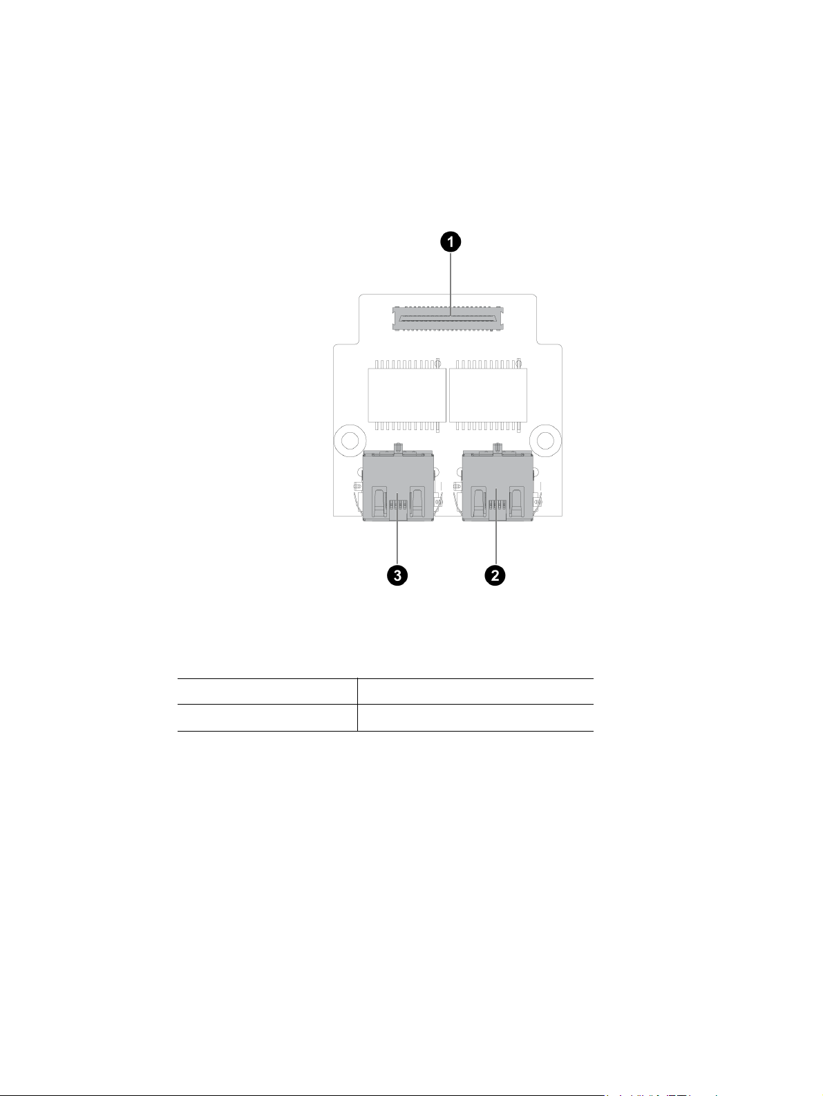
Connector and Component Locations of NIC Board
Figure 56. Connectors and Component Locations of NIC Board
1. Connector 2. Rear NIC2 Port
3. Rear NIC1 Port
50 Intel® Server System SR1680MV Service Guide
Page 73
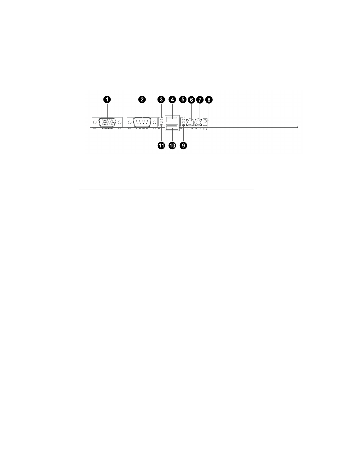
Connectors and Components of Front Panel
Figure 57. Connectors and Component Locations of Front Panel
1. Front VGA Port 2. Front Serial Port
3. NIC LED 4. Front USB Port
5. System Health LED 6. Power Button
7. Front UID Button 8. UID LED
9. Power LED 10. Front USB Port
11. SATA LED
Intel® Server System SR1680MV Service Guide 51
Page 74

10 GB IO Card (Optional Daughter Card)
Figure 58. Connectors and Components of 10 GB IO Card
1. PCI-E 2 Connector 2. PCI-E 1 Connector
3. 10 GB IO Port1 4. 10 GB IO Port2
52 Intel® Server System SR1680MV Service Guide
Page 75

InfiniBand Card (Optional Daughter Card)
Figure 59. Connectors and Components of InfiniBand Card
1. PCI-E 2 Connector 2. PCI-E 1 Connector
3. InfiniBand CX4 Port
Intel® Server System SR1680MV Service Guide 53
Page 76

Connector and Component Locations of HDD Backplane
Figure 60. Connectors and Components of 2.5-inch Pluggable HDD Backplane
1. HDD 0 Fail LED (CR4) 2. HDD 1 Fail LED (CR2)
3. HDD 1 Active LED
(CR1)
5. HDD 0 Active LED
(CR3)
7. Golden Fingers (J1)
4. SATA 1 Connector (J3)
6. SATA 0 HDD Connector (J2)
54 Intel® Server System SR1680MV Service Guide
Page 77

Connectors and Component Locations of PDB
Figure 61. Connectors and Component Locations of PDB
1. Power Supply Slot (J1) 2. Power Connector 1 (J5)
3. Power Connector 2
(J4)
5. Power Connector 4
(J2)
4. Power Connector 3 (J3)
The server board involves two system maintenance jumpers. One is MISC jumper, and the
other is an ICH functions jumper. Two jumpers are divided into five pin groups (refer to
Figure 62 “Location of MISC Jumper” on page -56 and Figure 63 “Location of ICH
Function Jumper” on page -57.
The location of two system maintenance jumpers on the motherboard is shown in the
following figure:
Intel® Server System SR1680MV Service Guide 55
Page 78

Figure 62. Location of MISC Jumper
Jumper Function
A Reserved
B Clear BMC Password
C Reserved
D Reserved
E Reserved
F Reserved
G Reserved
H Reserved
56 Intel® Server System SR1680MV Service Guide
Page 79

Figure 63. Location of ICH Function Jumper
Jumper Function
A Clear CMOS
B Clear Password
C Recovery RWH
D BIOS Protect
E RTC Reset
Intel® Server System SR1680MV Service Guide 57
Page 80

58 Intel® Server System SR1680MV Service Guide
Page 81

5 BIOS Setup and Configuration
This section describes the BIOS Setup Utility options. You can run the BIOS setup with or
without an operating system present. Onboard devices are configured with the BIOS
Setup utility that is embedded in flash ROM.
The configuration utilities allow you to modify the CMOS RAM and NVRAM. The actual
hardware configuration is accomplished by the BIOS POST routines and the BIOS PlugN-Play auto-configuration manager. The configuration utilities update a checksum for
both areas, so potential data corruption is detected by the BIOS before the hardware
configuration is saved. If the data is corrupted, the BIOS requests that the user reconfigure
the system and reboot.
Note: Because the BIOS code is the most often changed part of the server board design, the
BIOS information described in this section may be a little different compared to the actual
BIOS that contained in your server board.
BIOS Setup Utility
This section describes the ROM-resident setup utility that provides the means to configure
the platform. The BIOS Setup utility is part of the system BIOS and allows limited control
over onboard resources.
The user can disable embedded PCI devices through the setup menus. When these devices
are disabled through setup, their resources are freed.
Note: The BIOS options described in this section may or may not be present in pre-production
versions of the system BIOS. This section describes the BIOS utility as it is planned to be
at production and is subject to change. Option locations, in a given menu of the BIOS
Setup utility as described in this section, may be different from those observed on any one
pre-production version of the system BIOS.
The BIOS Setup utility screen is divided into four functional areas.
Table 5. BIOS Setup Utility Screen Descriptions
Functional Area Description
Keyboard Command Bar Located at the bottom of the right screen or as part of the help
screen. This bar displays the keyboard commands supported by
the setup utility.
Menu Selection Bar Located at the top of the screen. Displays the various major menu
selections available to the user. The Server Setup utility major
menus are: Main Menu, Advanced Menu, Boot Menu, Security
Menu, and Exit Menu.
Intel® Server System SR1680MV Service Guide 59
Page 82
Table 5. BIOS Setup Utility Screen Descriptions
Functional Area Description
Options Menu Each Option Menu occupies the left and center sections of the
screen. Each menu contains a set of features. Selecting certain
features within a major Option Menu drops you into sub-menus.
Item-Specific Help Screen An item-specific Help screen is located at the upside of the right
side of the screen.
Entering the BIOS Setup Utility
During the BIOS POST operation, the user is prompted to use the Del function key to
enter Setup as follows:
Press <F2> to run <Setup>.
Press <F11> to enter BBS POPUP.
A few seconds might pass before Setup is entered. This is the result of POST completing
test and initialization functions that must be completed before Setup can be entered. When
Setup is entered, the Main Menu options page displays.
Keyboard Command Bar
The right portion of the Setup screen provides a list of commands that are used to navigate
through the Setup utility. These commands display at all times.
Each menu page contains a number of configurable options and/or informational fields.
Depending on the level of security in affect, configurable options may or may not be
changed. If an option cannot be changed due to the security level, its selection field is
made inaccessible.
The Keyboard Command Bar supports the following:
Table 6. Keyboard Command Bar Description
Key Option Description
Enter Execute Command The Enter key is used to activate sub-menus when the selected
feature is a sub-menu, or to display a pick list if a selected option
has a value field, or to select a sub-field for multi-valued features
like time and date. If a pick list is displayed, the Enter key will
undo the pick list, and allow another selection in the parent menu.
60 Intel® Server System SR1680MV Service Guide
Page 83
Table 6. Keyboard Command Bar Description
Key Option Description
ESC Exit The ESC key provides a mechanism for backing out of any field.
This key will undo the pressing of the Enter key. When the ESC
key is pressed while editing any field or selecting features of a
menu, the parent menu is re-entered.
When the ESC key is pressed in any sub-menu, the parent menu
is re-entered. When the ESC key is pressed in any major menu,
the exit confirmation window is displayed and the user is asked
whether changes can be discarded. If "No" is selected and the
Enter key is pressed, or if the ESC key is pressed, the user is
returned to where they were before ESC was pressed without
affecting any existing settings. If "Yes" is selected and the Enter
key is pressed, Setup is exited and the BIOS continues with
POST.
Select Item The up arrow is used to select the previous value in a pick list, or
the previous options in a menu item's option list. The selected
item must then be activated by pressing the Enter key.
Select Item The down arrow is used to select the next value in a menu item's
Select Menu The left and right arrow keys are used to move between the
Tab Select Field The Tab key is used to move between fields. For example, Tab
- Change Value The minus key on the keypad is used to change the value of the
+ Change Value The plus key on the keypad is used to change the value of the
F9 Load Optimal Defaults Pressing F9 causes the following to display:
option list, or a value field's pick list. The selected item must then
be activated by pressing the Enter key.
major menu pages. The keys have no affect if a sub-menu or pick
list is displayed.
can be used to move from hours to minutes in the time item in the
main menu.
current item to the previous value. This key scrolls through the
values in the associated pick list without displaying the full list.
current menu item to the next value. This key scrolls through the
values in the associated pick list without displaying the full list. On
106-key Japanese keyboards, the plus key has a different scan
code than the plus key on the other keyboard, but will have the
same effect.
Setup Confirmation
Load Optimal Defaults?
[OK] [Cancel]
If “OK” is selected and the Enter key is pressed, all Setup fields
are set to their default values. If “Cancel” is selected and the
Enter key is pressed, or if the ESC key is pressed, the user is
returned to where they were before F9 was pressed without
affecting any existing field values.
Intel® Server System SR1680MV Service Guide 61
Page 84
Table 6. Keyboard Command Bar Description
Key Option Description
F10 Save and Exit Pressing F10 causes the following message to display:
Setup Confirmation
Save Configuration changes and exit setup?
[OK] [Cancel]
If “OK” is selected and the Enter key is pressed, all changes are
saved and Setup is exited. If “Cancel” is selected and the Enter
key is pressed, or the ESC key is pressed, the user is returned to
where they were before F10 was pressed without affecting any
existing values.
BIOS Setup Utility Menu
The Setup Utility menu bar displays the five primary menu selections. For detailed
information and screenshots of these Setup Utility menus and their related submenus,
refer to the following sections.
Note: Settings with * in tables are BIOS Setup defaults of BIOS Setup Utility Menu.
62 Intel® Server System SR1680MV Service Guide
Page 85
Main Menu
Table 7. Main Menu of BIOS Setup Utility
BIOS Setup Utility
Main
System Overview
AMIBIOS Version :08.00.15
Build Date :02/16/09
ID :MARBLE VALLEY005
Processor
Intel(R) Xeon(R) CPU E5540
@ 2.53 GHz
Speed :2533 MHz
Count :2
System Memory
Size :6144 MB
System Time [09:52:34]
System Date [Fri 11/14/2008]
Advanced Boot Security Exit
Use [ENTER], [TAB], or [SHIFT-TAB] to
select a field.
Select Screen
Select Screen
+ - Change Field
Tab Select Field
F1 General Help
F10 Save and Exit
ESC Exit
V02.61 © Copyright 1985-2006, American Megatrends, Inc.
Table 8. Main Menu Fields
Menu Fields Settings Description
System time Current Time User [ENTER], [TAB] or [SHIFT-TAB] to select a field.
Use [+] or [-] to configure system Time.
System date Current date User [ENTER], [TAB] or [SHIFT-TAB] to select a field.
Use [+] or [-] to configure system Time.
Intel® Server System SR1680MV Service Guide 63
Page 86
Advanced Menu
Table 9. Advanced Menu of BIOS Setup Utility
BIOS Setup Utility
Main
Advanced Settings
WARNING: Setting wrong
values in below sections may
cause system to malfunction.
• CPU Configuration
• SATA Configuration
• Super IO Configuration
• USB Configuration
• PCI Express*
• IPMI Configuration
• Remote Access
Advanced
Configuration
Configuration
Boot Security Exit
Configure CPD
Select Screen
Select Screen
+ - Change Field
Tab Select Field
F1 General Help
F10 Save and Exit
ESC Exit
V02.61 © Copyright 1985-2006, American Megatrends, Inc.
64 Intel® Server System SR1680MV Service Guide
Page 87
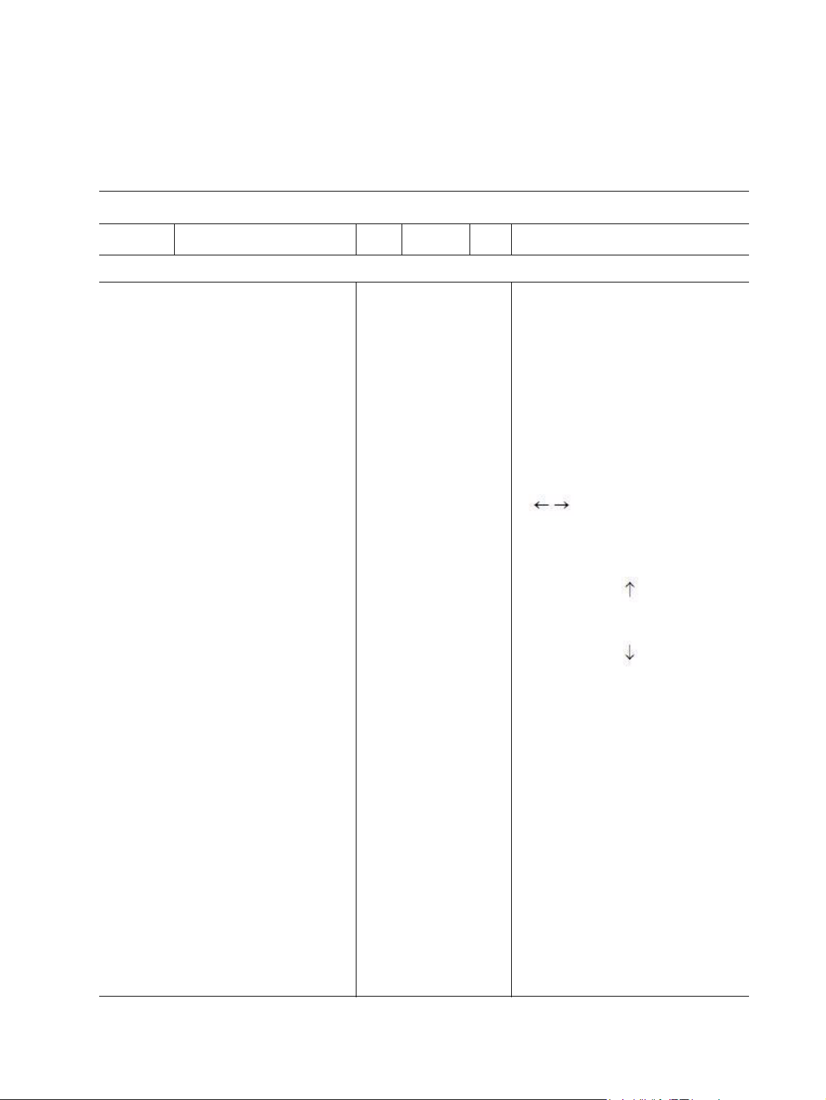
Table 10. CPU Configuration Submenu
BIOS Setup Utility
Main
Configure advanced CPU settings
Module Version:3F.13
Manufacturer: :Intel
Intel(R) Xeon(R) CPU :E5540 @ 2.53 GHz
Frequency 2.53 GHz
BCLK Speed : 133 MHz
Cache L1 : 128 KB
Cache L2 : 1024 KB
Cache L3 : 8192 KB
Ratio Status : Unlocked (Min:12, Max:19)
Ratio Actual Value :19
CPU Revision :D0
Current QPI Frequency : 5.866 GT
Current Memory Frequency :1066 MHz
Ratio CMOS Setting [19]
Hardware Prefetcher [Enabled]
Adjacent Cache Line Prefetch [Enabled]
Max CPUID Value Limit [Enabled]
Intel(R) Virtualization Tech [Enabled]
Execute-Disable Bit Capacity [Enabled]
Intel(R) HT Technology [Enabled]
Active Processor Cores [All]
A20M [Disabled]
Intel(R) SpeedStep(tm) tech [Enabled]
Intel(R) C-STATE tech [Disabled]
QPI Link Speed [Full-Speed]
QPI Frequency [Auto]
API L0s and L1 [Disabled]
Memory Frequency [Auto]
Memory Mode [Independent]
Demand Scrubbing [Enabled]
Patrol Scrubbing [Disabled]
Serial Debug Message Level [None]
Advanced
Boot Security Exit
For UP platforms, leave it enabled. For
DP/MP servers, it may use to tune
performance to the specific application.
Select Screen
Select Screen
+ - Change Field
Tab Select Field
F1 General Help
F10 Save and Exit
ESC Exit
Intel® Server System SR1680MV Service Guide 65
Page 88
Table 10. CPU Configuration Submenu
BIOS Setup Utility
Main
Configure advanced CPU settings
Advanced
V02.61 © Copyright 1985-2006, American Megatrends, Inc.
Boot Security Exit
Table 11. CPU Configuration Submenu Fields
Menu Fields Settings Description
Advanced/Configure advanced CPU settings
Ratio CMOS Setting 19* Sets the ratio between CPU core clock and the
FSB frequency.
Hardware Prefetcher Disabled
Enabled*
Adjacent Cache Line
Prefetch
Max CPUID Value Limit Disabled*
Disabled
Enabled*
Enabled
For UP platforms, leave it enabled. For DP/MP
servers, it may use to tune performance to the
specific application.
For UP platforms, leave it enabled. For DP/MP
servers, it may use to tune performance to the
specific application.
Disabled for Microsoft Windows XP*
Intel(R) Virtualization
Te c h
Execute-Disable Bit
Capability
Intel(R) HT Technology Disabled*
Active Processor Cores All*
A20M Disabled*
Intel(R) SpeedStep(tm)
tech
Intel(R) C-STATE tech Disabled*
Disabled*
Enabled
Disabled
Enabled
Enabled
1
2
Enabled
Disabled
Enabled*
Enabled
When enabled, a VMM can utilize the additional
HW Caps. Provided by Intel(R) Virtualization
Tech. Note: A full reset is required to change
the setting.
When disabled, force the XD feature flag to
always return 0.
When “Disabled” only one thread per enabled
core is enabled.
Number of cores to enable in each processor
package.
Legacy operating systems and APs may need
A20M enabled.
Disable: Disable GV3
Enable: Enable GV3
CState: CPU idle is set to C2/C3/C4
66 Intel® Server System SR1680MV Service Guide
Page 89
Table 11. CPU Configuration Submenu Fields
Menu Fields Settings Description
QPI Links Speed Slow-Mode
Full-Speed*
QPI Frequency Auto *
4.800GT
5.866GT
6.400GT
QPI L0s and L1 Disabled *
Enabled
Memory Frequency Auto *
Force DDR-800
Force DDR-1066
Force DDR-1333
Memory Mode Independent*
Channel Mirroring
Lockstep
Sparing
To transition the QPI links to full-speed or leave
them in Slow-mode.
Transition the links to the specified speed when
transitioning the links to full-speed. (if supported
by all components).
Enable/Disable L0s and L1.
Forces a DDR3 frequency slower than the
common tCK detected via SPD.
Independent:
Independent channel.
Mirroring:
Mirrors channel space between channel.
Lockstep:
Lockstep between channel 0 and 1.
Spare:
Sparing mode.
Demand Scrubbing Disabled*
Enabled
Patrol Scrubbing Disabled*
Enabled
Serial Debug Message
Level
Intel® Server System SR1680MV Service Guide 67
NONE*
MIN
MAX
TEST
ECC demand scrub enable/disable.
ECC patrol scrub enable/disable.
Specifies what level of debug messages to
display.
Page 90

SATA Configuration Submenu
Table 12. SATA Configuration Submenu1
BIOS Setup Utility
Main
SATA Configuration
Configure SATA AS
Advanced
• Primary IDE Master
• Primary IDE Slave
• Secondary IDE Master
• Secondary IDE Slave
Hard Disk Write Protect
IDE Detect Time Out (Sec)
ATA(PI) 80Pin Cable Detection
NOTE1
[IDE]
:[Not
Detected]
:[Not
Detected]
:[Not
Detected]
:[Not
Detected]
[Disabled]
[35]
[Host &
Device]
Boot Security Exit
Configure the IDE device(s).
NOTE1:
As Compatible only support IDE mode,
“Configure SATA AS” will be hidden
when “SATA Configuration” is
compatible.
Select Screen
Select Screen
+ - Change Field
Tab Select Field
F1 General Help
F10 Save and Exit
ESC Exit
V02.61 © Copyright 1985-2006, American Megatrends, Inc.
68 Intel® Server System SR1680MV Service Guide
Page 91
Table 13. SATA Configuration Submenu2
BIOS Setup Utility
Main
SATA Configuration [Enhanced]
Configure SATA AS
Advanced
• Primary IDE Master
• Primary IDE Slave
• Secondary IDE Master
• Secondary IDE Slave
Hard Disk Write Protect
IDE Detect Time Out (Sec)
ATA(PI) 80Pin Cable
Detection
Boot Security Exit
[IDE] Configure the IDE device(s).
:[Not
Detected]
:[Not
Detected]
:[Not
Detected]
:[Not
Detected]
[Disabled]
[35]
[Host &
Device]
Options
Disabled
Compatible
Enhanced
Select Screen
Select Screen
+ - Change Field
Tab Select Field
F1 General Help
F10 Save and Exit
ESC Exit
V02.61 © Copyright 1985-2006, American Megatrends, Inc.
Intel® Server System SR1680MV Service Guide 69
Page 92

Table 14. SATA Configuration Submenu3
BIOS Setup Utility
Main
SATA Configuration [Enhanced]
Configure SATA AS
Advanced
• Primary IDE Master
• Primary IDE Slave
• Secondary IDE Master
• Secondary IDE Slave
Hard Disk Write Protect
IDE Detect Time Out (Sec)
ATA(PI) 80Pin Cable
Detection
Boot Security Exit
[RAID] Configure the IDE device(s).
:[Not
Detected]
:[Not
Detected]
:[Not
Detected]
:[Not
Detected]
[Disabled]
[35]
[Host &
Device]
Select Screen
Select Screen
+ - Change Field
Tab Select Field
F1 General Help
F10 Save and Exit
ESC Exit
V02.61 © Copyright 1985-2006, American Megatrends, Inc.
70 Intel® Server System SR1680MV Service Guide
Page 93

Table 15. SATA Configuration Submenu4
BIOS Setup Utility
Main
SATA Configuration [Enhanced]
Configure SATA AS
Advanced
• AHCI PORT1
• AHCI PORT2
• AHCI PORT3
• AHCI PORT4
Hard Disk Write Protect
IDE Detect Time Out (Sec)
ATA(PI) 80Pin Cable
Detection
Boot Security Exit
[AHCI] Configure the IDE device(s).
:[Not
Detected]
:[Not
Detected]
:[Not
Detected]
:[Not
Detected]
[Disabled]
[35]
[Host &
Device]
Select Screen
Select Screen
+ - Change Field
Tab Select Field
F1 General Help
F10 Save and Exit
ESC Exit
V02.61 © Copyright 1985-2006, American Megatrends, Inc.
Intel® Server System SR1680MV Service Guide 71
Page 94

Menu Fields Settings Description
SATA Configuration
Table 16. SATA Configuration Submenu Fields
SATA Configuration Disabled
Compatible*
Enhanced
Configure SATA as IDE*
RAID
AHCI
Hard Disk Write Protect Disabled*
Enable
IDE Detect Time Out
(Sec)
0
5
10
15
20
25
30
35*
Options
Disabled
Compatible
Enhanced
Options
IDE
RAID
AHCI
Disable/Enable device write protection.
this will effective only if device is accessed through BIOS.
Select the time out value for detecting ATA/ATAPI
device(s).
ATA(PI) 80Pin Cable
Detection
72 Intel® Server System SR1680MV Service Guide
Host & Device*
Host
Device
Select the mechanism for detecting 80Pin ATA(PI) Cable.
Page 95

Super IO Chipset Submenu
Table 17. Super IO Chipset Submenu
BIOS Setup Utility
Main
Configure PILOT Super IO Chipset
Serial Port Address [3F8/IRQ4] Configure Super IO Chipset PILOT
Advanced
Boot Security Exit
Select Screen
Select Screen
+ - Change Field
Tab Select Field
F1 General Help
F10 Save and Exit
ESC Exit
V02.61 © Copyright 1985-2006, American Megatrends, Inc.
Intel® Server System SR1680MV Service Guide 73
Page 96
Table 18. SATA Configuration Submenu Fields
Menu Fields Settings Description
Advanced/Super IO Configuration
Serial Port Address Disabled
3F8/IRQ4
2F8/IRQ3
3F8/IRQ4
2F8/IRQ3
Allows BIOS to select Serial Port1 Base Address.
74 Intel® Server System SR1680MV Service Guide
Page 97
USB Configuration Submenu
Table 19. USB Configuration Submenu
BIOS Setup Utility
Main
USB Configuration
Module Version - 2.24.3-13.4
USB Devices Enabled
2 Keyboards, 3 Mice, 1 Hub, 2 Drives
Legacy USB Support [Enabled]
USB 2.0 Controller mode [HiSpeed]
BIOS EHCI Hand-Off [Enabled]
Hotplug USB FDD Support [Auto]
Advanced
• USB Mass Storage Device
Configuration
BootSecurity Exit
Configure the USB support.
Select Screen
Select Screen
+ - Change Field
Tab Select Field
F1 General Help
F10 Save and Exit
ESC Exit
V02.61 © Copyright 1985-2006, American Megatrends, Inc.
Table 20. USB Configuration Submenu Fields
Menu Fields Settings Description
Advanced/USB Configuration
Legacy USB Support Disabled
Enabled*
Auto
Intel® Server System SR1680MV Service Guide 75
Enables support for legacy USB. AUTO option disables
legacy support if no USB devices are connected.
Page 98
Table 20. USB Configuration Submenu Fields
Menu Fields Settings Description
USB 2.0 Controller mode FullSpeed
HiSpeed*
BIOS EHCI Hand-Off Disabled
Enabled*
Hotplug USB FDD
Support
Disabled
Enabled
Auto*
Configures the USB 2.0 controller in HiSpeed (480 Mbps)
or FullSpeed (12Mbps)
This is a workaround for operating systems without EHCI
hand-off support. The EHCI ownership change should
claim by EHCI driver.
A dummy FDD device is created that will be associated
with the hotplugged FDD later. Auto option creates this
dummy device only if there is no FDD present.
76 Intel® Server System SR1680MV Service Guide
Page 99
USB Mass Storage Device Configuration Submenu
Table 21. USB Mass Storage Device Configuration Submenu
BIOS Setup Utility
Main
USB Mass Device Storage Configuration
USB Mass Storage Reset Delay [20 Sec]
Device #1 AMI Virtual CDROM
Emulation Type [Auto]
Device #1 AMI Virtual Floppy #N
Emulation Type [Auto]
Advanced
Boot Security Exit
Configure the USB Mass Storage
Device Classes.
Select Screen
Select Screen
+ - Change Field
Tab Select Field
F1 General Help
F10 Save and Exit
ESC Exit
V02.61 © Copyright 1985-2006, American Megatrends, Inc.
Intel® Server System SR1680MV Service Guide 77
Page 100

Table 22. USB Mass Storage Device Configuration Submenu Fields
Menu Fields Settings Description
Advanced/USB Configuration
USB Mass Storage Reset
Delay
Emulation Type Auto*
10 Sec
20 Sec*
30 Sec
40 Sec
Floppy
Forced FDD
Hard Disk
CDROM
Number of seconds POST waits for the USB mass
storage device after start unit command.
If Auto, USB devices less than 530 MB will be emulated
as Floppy and remaining as hard drive. Forced FDD
option can be used to force a HDD-formatted drive to
boot as FDD (for example, a zip drive).
78 Intel® Server System SR1680MV Service Guide
 Loading...