

Page 1

Intel® Server System SR1670HV
Service Guide
Intel Part Number: E74138-004
A Guide for Technically Qualified Assemblers of Intel® Identified Subassemblies/Products
Page 2

Disclaimer
Disclaimer
Information in this document is provided in connection with Intel® products. No license, express or implied, by estoppel or
otherwise, to any intellectual property rights is granted by this document. Except as provided in Intel’s Terms and Conditions
of Sale for such products, Intel assumes no liability whatsoever, and Intel disclaims any express or implied warranty, relating
to sale and/or use of Intel products including liability or warranties relating to fitness for a particular purpose, merchantability,
or infringement of any patent, copyright or other intellectual property right. Intel products are not designed, intended or
authorized for use in any medical, life saving, or life sustaining applications or for any other application in which the failure of
the Intel product could create a situation where personal injury or death may occur. Intel may make changes to
specifications and product descriptions at any time, without notice.
Intel server boards contain a number of high-density VLSI and power delivery components that need adequate airflow for
cooling. Intel’s own chassis are designed and tested to meet the intended thermal requirements of these components when
the fully integrated system is used together. It is the responsibility of the system integrator that chooses not to use Intel
developed server building blocks to consult vendor datasheets and operating parameters to determine the amount of airflow
required for their specific application and environmental conditions. Intel Corporation can not be held responsible if
components fail or the server board does not operate correctly when used outside any of their published operating or nonoperating limits.
Intel, Intel Pentium, and Intel Xeon are trademarks or registered trademarks of Intel Corporation or its subsidiaries in the
United States and other countries.
* Other names and brands may be claimed as the property of others.
Copyright © 2010, Intel Corporation. All Rights Reserved
ii Intel
®
Server System SR1670HV Service Guide
Page 3

Disclaimer
<This page is intentionally left blank.>
®
Intel
Server System SR1670HV Service Guide iii
Page 4

Preface
Preface
About this Manual
Thank you for purchasing and using the Intel® Server System SR1670HV.
This manual is written for system technicians who are responsible for troubleshooting,
upgrading, and repairing this server system. This document provides a brief overview of
the features of the board/chassis, a list of accessories or other components you may
need, troubleshooting information, and instructions on how to add and replace
components on the Intel
refer to the following Intel web site:
®
Server System SR1670HV. For the latest version of this manual,
http://support.intel.com/support/motherboards/server/SR1670HV/
Manual Organization
Chapter 1 provides a brief overview of the Intel® Server System SR1670HV. In this
chapter, you will find a list of the system features, product photos, and product diagrams to
help you identify components and their locations.
Chapter 2 lists the hardware setup procedures you must perform when installing or
removing system components.
Chapter 3 describes how to install the optional components.
Chapter 4 includes procedures to follow when replacing common FRUs.
Chapter 5 describes the functions of all server board jumpers, connectors, and LEDs.
Chapter 6 describes the update process and configurable features of the system BIOS
Chapter 7 provides an overview of the embedded SATA RAID options and how to
configure RAID sets.
Chapter 8 provides instructions for installing the necessary drivers for different system
components.
Chapter 9 provides an Issue Submittal form which can be used when reporting system
issues back to Intel Corporation.
Chapter 10 provides Intel Support and Warranty information.
Chapter 11 details product safety information.
iv Intel
®
Server System SR1670HV Service Guide
Page 5

Preface
Additional Information and Software
Documentation and software for this server product are available on the Intel Resource
CD that shipped with your Intel server product. Software updates and additional
information can be obtained at the following Intel web site:
http://support.intel.com/support/motherboards/server/SR1670HV/
Unless otherwise indicated in the following table, once on this Web page, type the
document or software name in the search field at the left side of the screen and select the
option to search “This Product.”
For this information or software Use this Document or Software
For in-depth technical information
about this product
For information needed to provide
service and support for this product
Embedded RAID Configuration and
Support
SKU information, Spares and
Accessories available for this Intel
Server product
Hardware (peripheral boards,
adapter cards) and operating
systems that have been tested with
this product
Processors that have been tested
with this product
DIMMs that have been tested with
this product
For drivers Driver (for an extensive list of drivers available)
For firmware and BIOS updates Firmware Update
Technical Product Specification (TPS)
Service Guide – (This document)
Intel® Matrix Storage Manager Users Manual
LSI* Embedded MegaRAID Software Users Manual
Spares and Configuration Guide
Tested Hardware and Operating System List
Supported Processors
Supported Memory
Operating System Driver (for operating system drivers)
®
Intel
Server System SR1670HV Service Guide v
Page 6

Contents
Contents
1. Product Introduction...................................................................................... 1
1.1 System Package Contents............................................................................................. 1
1.2 System Features ............................................................................................................ 1
1.3 Front Panel Features .....................................................................................................2
1.4 Rear Panel Features ...................................................................................................... 3
1.5 Internal Features ............................................................................................................ 3
1.6 System LED Information ................................................................................................ 6
1.6.1 Front Control Panel LEDs................................................................................ 6
1.6.2 RJ-45 LAN Ports 1 and 2 LEDs....................................................................... 7
1.6.3 HDD Status LED.............................................................................................. 7
1.7 Cable Connections......................................................................................................... 7
1.7.1 Pre-Connected System Cables ....................................................................... 8
2. Hardware Setup.............................................................................................. 9
2.1 Chassis Cover................................................................................................................ 9
2.1.1 Removing the Chassis Cover .......................................................................... 9
2.2 Central Processing Unit (CPU) ......................................................................................9
2.2.1 Installing the Processor ................................................................................. 10
2.2.2 Installing the Processor Heatsink .................................................................. 13
2.2.3 Removing the Processor Heatsink ................................................................ 14
2.3 System Memory ........................................................................................................... 15
2.3.1 Overview........................................................................................................ 15
2.3.2 Memory Support ............................................................................................ 16
2.3.3 Installing a DIMM........................................................................................... 18
2.3.4 Removing a DIMM......................................................................................... 19
2.4 Installing a PCI Express* Add-In Card to the Riser Bracket......................................... 20
2.5 Installing the BMC Management Module ..................................................................... 22
2.6 Hard Disk Drives .......................................................................................................... 23
3. Installing the Rackmount Rail Kit ............................................................... 25
3.1 Attaching the Rails to the Server.................................................................................. 25
3.2 Attaching the Rack Rails .............................................................................................. 26
3.3 Rackmounting the Server............................................................................................. 27
4. System Service............................................................................................. 28
4.1 Replacing Power Supply Units (PSUs) ........................................................................ 28
4.2 Replacing System Fans ............................................................................................... 29
4.3 SATA/SAS BackPlane Replacement ........................................................................... 30
4.4 Front Control Panel Replacement................................................................................ 33
5. Jumpers, Connectors, and LEDs................................................................ 35
5.1 Configuration and Support Jumpers ............................................................................35
5.1.1 Clear RTC RAM (CLRTC1) ........................................................................... 35
5.1.2 VGA Controller Setting (3-pin VGA_SW1) .................................................... 36
5.1.3 DDR3 Voltage Control Setting (4-pin LVDDR3_SEL1, LVDDR3_SEL2) ...... 36
5.1.4 LAN Controller Setting (3-poin LAN_SW1, LAN_SW2)................................. 37
vi Intel
®
Server System SR1670HV Service Guide
Page 7

Contents
5.1.5 Intel® ICH10R SATA Port SW RAID Setting (3-pin RAID_SEL1) ..................37
5.1.6 Force BIOS Recovery Setting (3-pin RECOVERY1)..................................... 38
5.2 Server Board Connectors............................................................................................. 39
5.2.1 Serial ATA Connectors (7-pin SATA1, SATA2, SATA3, SATA4) .................. 39
5.2.2 Internal USB Connectors (A-Type USB4; 5x1 pin USB3) .............................39
5.2.3 System Fan Connectors (4-pin FRNT_FAN1, FRNT_FAN2, FRNT_FAN3,
FRNT_FAN4)................................................................................................. 40
5.2.4 Serial General Purpose Input/Output Connector (6-1 pin SGPIO1) .............. 40
5.2.5 BMC Management Module Header (BMC_FW1) .......................................... 41
5.2.6 Power Supply SMBus Connectors (6x1 pin JP1, JP2) .................................. 41
5.2.7 Main Power Connectors (20-pin PWR1, 20-pin PWR2) ................................ 42
5.2.8 Peripheral Power Connector (4-pin PWR3)................................................... 42
5.2.9 System Panel Connector (20-pin PANEL1)................................................... 42
5.2.10 Auxiliary Panel Connector (20-pin AUX_PANEL1)........................................ 44
5.3 Internal LEDs ...............................................................................................................45
5.3.1 Standby Power LED ...................................................................................... 45
5.3.2 CPU Warning LED (ERR_CPU1, ERR_CPU2)............................................. 45
5.3.3 System Identification LED .............................................................................46
5.3.4 BMC LED (BMC_LED1) ................................................................................ 46
6. BIOS Updates and Configuration ............................................................... 47
6.1 Updating System BIOS ................................................................................................ 47
6.2 BIOS Recovery Process ..............................................................................................48
6.3 BIOS Setup Utility ........................................................................................................49
6.3.1 Accessing BIOS Setup Utility ........................................................................50
6.3.2 BIOS Setup Features and Navigation ...........................................................50
6.3.3 Main Menu..................................................................................................... 51
6.3.4 Advanced Menu............................................................................................. 57
6.3.5 Server Menu .................................................................................................. 73
6.3.6 Boot Menu ..................................................................................................... 75
6.3.7 Exit Menu....................................................................................................... 80
7. Embedded SATA RAID ................................................................................ 81
7.1 Selecting a RAID option ...............................................................................................81
7.2 Enabling RAID in the BIOS Setup................................................................................ 82
7.3 SATA RAID Setup........................................................................................................ 82
7.3.1 LSI* Software RAID Configuration Utility....................................................... 82
7.3.2 Intel® Matrix Storage Manager Configuration Utility....................................... 90
8. Driver Installation......................................................................................... 93
8.1 RAID Driver Installation................................................................................................ 93
8.1.1 Creating a RAID Driver Disk.......................................................................... 93
8.1.2 Installing the RAID Controller Driver.............................................................. 94
8.2 Intel® Chipset Device Installation.................................................................................. 99
8.3 LAN Driver Installation ...............................................................................................101
8.4 VGA Driver Installation............................................................................................... 103
8.5 Management Applications and Utilities Installation .................................................... 105
8.5.1 Running the Resource CD........................................................................... 105
8.5.2 Drivers Menu ............................................................................................... 105
8.5.3 Utilities Menu ............................................................................................... 106
8.5.4 Make Disk Menu.......................................................................................... 106
®
Intel
Server System SR1670HV Service Guide vii
Page 8
Contents
8.5.5 Contact Information ..................................................................................... 106
9. Intel® Server Issue Report Form................................................................ 107
10. Getting Help ........................................................................................ 112
10.1 Warranty Information.................................................................................................. 112
11. Safety Information .............................................................................. 113
Server Safety Information ...................................................................................................114
Safety Warnings & Cautions ............................................................................................... 114
Intended Application Uses ..................................................................................................115
Site Selection ...................................................................................................................... 115
Equipment Handling Practices............................................................................................ 115
Power and Electrical Warnings ........................................................................................... 115
System Access Warnings ...................................................................................................116
Rack Mount Warnings......................................................................................................... 117
Electrostatic Discharge (ESD)............................................................................................. 118
CAUTION ............................................................................................. 118
Other Hazards..................................................................................................................... 119
CAUTION..................................................................................................... 119
Sicherheitshinweise für den Server..................................................................................... 120
Sicherheitshinweise und Vorsichtsmaßnahmen .................................................................120
Zielbenutzer der Anwendung .............................................................................................. 121
Standortauswahl .................................................................................................................121
Handhabung von Geräten................................................................................................... 121
Warnungen zu Netzspannung und Elektrizität.................................................................... 121
Warnhinweise für den Systemzugang................................................................................. 122
Warnhinweise für Racks .....................................................................................................123
Elektrostatische Entladungen (ESD)................................................................................... 124
VORSICHT ........................................................................................... 124
Andere Gefahren................................................................................................................. 124
VORSICHT................................................................................................... 125
Consignes de sécurité sur le serveur.................................................................................. 126
Sécurité : avertissements et mises en garde ...................................................................... 126
Domaines d’utilisation prévus .............................................................................................127
Sélection d’un emplacement ............................................................................................... 127
Pratiques de manipulation de l’équipement ........................................................................ 127
Alimentation et avertissements en matière d’électricité ...................................................... 127
Avertissements sur l’accès au système .............................................................................. 129
Avertissements sur le montage en rack.............................................................................. 129
Décharges électrostatiques (ESD)...................................................................................... 130
ATTENTION ......................................................................................... 130
Autres risques ..................................................................................................................... 130
viii Intel
®
Server System SR1670HV Service Guide
Page 9
Contents
ATTENTION................................................................................................. 131
Información de seguridad del servidor................................................................................ 132
Advertencias y precauciones sobre seguridad ................................................................... 132
Aplicaciones y usos previstos ............................................................................................. 133
Selección de la ubicación.................................................................................................... 133
Manipulación del equipo .....................................................................................................133
Advertencias de alimentación y eléctricas .......................................................................... 133
Advertencias el acceso al sistema...................................................................................... 134
Advertencias sobre el montaje en bastidor......................................................................... 135
Descarga electrostática (ESD)............................................................................................ 136
PRECAUCIÓN...................................................................................... 136
Otros riesgos....................................................................................................................... 136
PRECAUCIÓN ............................................................................................. 137
服务器安全信息 ...................................................................................................................138
安全警告与注意事项............................................................................................................ 138
预期应用使用....................................................................................................................... 138
场地选择.............................................................................................................................. 139
设备操作规范....................................................................................................................... 139
电源与电气警告 ...................................................................................................................139
系统使用警告....................................................................................................................... 140
机架固定件警告 ...................................................................................................................141
静电放电 (ESD) ...................................................................................................................141
注意事项 ................................................................................... 141
其他危险.............................................................................................................................. 141
注意事项 ....................................................................................................... 142
®
Intel
Server System SR1670HV Service Guide ix
Page 10

List of Figures
List of Figures
Figure 1. Server System Features ................................................................................................3
Figure 2. System Features – Back Panel .....................................................................................3
Figure 3. System Component Identification .................................................................................. 4
Figure 4. Server Node Connectors and Components................................................................... 5
Figure 5. Front Control Panel LEDs..............................................................................................6
Figure 6. RJ-45 Ports 1 and 2 LEDs ............................................................................................. 7
Figure 7. HDD Status LED............................................................................................................ 7
Figure 8. Cable Connections ........................................................................................................8
Figure 9. Rear Panel Thumbscrews .............................................................................................9
Figure 10. Sliding the Chassis Cover............................................................................................9
Figure 11. LGA1366 Socket........................................................................................................ 10
Figure 12. Retention Tab and Load Lever .................................................................................. 11
Figure 13. Load Plate.................................................................................................................. 11
Figure 14. PnP Cap ....................................................................................................................11
Figure 15. CPU Notch and Alignment Key.................................................................................. 12
Figure 16. Applying Thermal Paste............................................................................................. 12
Figure 17. Closing the Load Plate...............................................................................................13
Figure 18. Installing the Heatsink (Passive Heatsink Shown)..................................................... 14
Figure 19. Removing the Heatsink.............................................................................................. 15
Figure 20. DDR3 DIMM Sockets Location .................................................................................. 16
Figure 21. Unlocked Retaining Clips........................................................................................... 19
Figure 22. Locked Retaining Clips .............................................................................................. 19
Figure 23. DIMM Notch............................................................................................................... 19
Figure 24. Riser Card Bracket ....................................................................................................20
Figure 25. Removing the Screw from Slot Bay ........................................................................... 20
Figure 26. PCI Express* x 16 Card............................................................................................. 20
Figure 27. Pressing Rising Card Bracket for Golden Connectors to Fit...................................... 21
Figure 28. BMC_FW1 Header ....................................................................................................22
Figure 29. Orienting the Management Module Card................................................................... 22
Figure 30. Server Management LAN Port................................................................................... 22
Figure 31. Hard Disk Drives........................................................................................................ 23
Figure 32. Releasing the Drive Tray ........................................................................................... 23
Figure 33. Placing a SATAII/SAS Hard Disk Drive on the Tray .................................................. 23
Figure 34. Pushing the Tray Lever.............................................................................................. 24
Figure 35. Rackmount Rail Kit Items ..........................................................................................25
Figure 36. Screw positions on the rail......................................................................................... 25
Figure 37. Attaching the Front End of the Server Rail to Side of Chassis .................................. 26
Figure 38. Sliding the Server Rail ............................................................................................... 26
Figure 39. Securing the Server Rail With Screws....................................................................... 26
Figure 40. Positioning the Rack Rail to 1U Space on Rack........................................................ 27
Figure 41. Mounting Ear .............................................................................................................27
Figure 42. Holding and Pressing the PSU Latch ........................................................................28
Figure 43. Pulling Out the Failed PSU ........................................................................................ 28
Figure 44. Pushing the New PSU Into the Chassis ....................................................................28
Figure 45. Disconnecting System Fan Cable.............................................................................. 29
Figure 46. Lifting System Fan ..................................................................................................... 29
Figure 47. Inserting Fan Into the Fan Cage ................................................................................ 29
x Intel
®
Server System SR1670HV Service Guide
Page 11

List of Figures
Figure 48. Restoring the Chassis Cover ..................................................................................... 30
Figure 49. Screws On Hard Disk Drive Bay Module ................................................................... 30
Figure 50. Sliding the Hard Disk Drive Bay Module.................................................................... 30
Figure 51. Connected Cables and Backplane Expose ...............................................................31
Figure 52. Front Panel Cables .................................................................................................... 31
Figure 53. Cable Bundles in the Hard Disk Drive Bay Module ...................................................32
Figure 54. SATA Cable Connection Order.................................................................................. 32
Figure 55. Aligning the Module with the Alignment Slots on the Chassis ................................... 33
Figure 56. Control Panel Module Screw ..................................................................................... 33
Figure 57 .................................................................................................................................... 34
Figure 58 Detached Control Panel Module................................................................................. 34
Figure 59. Clear RTC RAM......................................................................................................... 35
Figure 60. VGA Controller Setting ..............................................................................................36
Figure 61. DDR3 Voltage Control Setting ................................................................................... 37
Figure 62. LAN Controller Setting ...............................................................................................37
Figure 63. Intel
®
ICH10R SATA Port SW RAID Setting ..............................................................38
Figure 64. Force BIOS Recovery Setting.................................................................................... 38
Figure 65. SATA Connectors ......................................................................................................39
Figure 66. USB 2.0 Connectors .................................................................................................. 39
Figure 67. Front Fan Connectors................................................................................................ 40
Figure 68. Serial General Purpose I/O Connector ...................................................................... 40
Figure 69. BMC Management Module Header ...........................................................................41
Figure 70. Power Supply SMBus Connectors............................................................................. 41
Figure 71. Main Power Connectors ............................................................................................42
Figure 72. Peripheral Power Connector (4-pin PWR3)............................................................... 42
Figure 73. System Panel Connector ........................................................................................... 43
Figure 74. Auxiliary Panel Connector .........................................................................................44
Figure 75. Standby Power LED ..................................................................................................45
Figure 76. ERR CPU LED........................................................................................................... 45
Figure 77. System Identification LED.......................................................................................... 46
Figure 78. BMC LED (BMC_LED1) ............................................................................................46
Figure 79. Updating the BIOS in DOS ........................................................................................ 48
Figure 80. Recovering the BIOS Using the Force BIOS Update Jumper ................................... 49
Figure 81. BIOS Menu Screen.................................................................................................... 50
Figure 82. Pop-Up Window......................................................................................................... 51
Figure 83. Main Menu ................................................................................................................. 52
Figure 84. SATA1-4 Submenu.................................................................................................... 52
Figure 85. IDE Configuration Menu ............................................................................................54
Figure 86. AHCI Configuration Menu.......................................................................................... 55
Figure 87. Status of Auto-Detection of SATA Devices Menu...................................................... 55
Figure 88. System Information Menu.......................................................................................... 56
Figure 89. System Memory Information Menu............................................................................ 56
Figure 90. Advanced Menu......................................................................................................... 57
Figure 91. CPU Configuration Menu........................................................................................... 58
Figure 92. CPU Configuration Menu, Continued ........................................................................58
Figure 93. Chipset Configuration Menu ...................................................................................... 61
Figure 94. CPU Bridge Chipset Configuration Menu .................................................................. 61
Figure 95. CPU Bridge Chipset Configuration Menu, Continued................................................ 62
Figure 96. North Bridge Chipset Configuration Menu ................................................................. 64
Figure 97. South Bridge Chipset Configuration Menu ................................................................64
®
Intel
Server System SR1670HV Service Guide xi
Page 12

List of Figures
Figure 98. Intel VT-d Configuration Menu................................................................................... 65
Figure 99. Legacy Device Configuration Menu........................................................................... 65
Figure 100. USB Configuration Menu ......................................................................................... 66
Figure 101. PCIPnP Configuration Menu.................................................................................... 67
Figure 102. Power On Configuration Menu ................................................................................68
Figure 103. Event Log Configuration Menu ................................................................................ 69
Figure 104. Hardware Monitor Configuration Menu.................................................................... 70
Figure 105. Hardware Monitor Configuration Menu, Continued ................................................. 70
Figure 106. PCI Express* Configuration Menu ........................................................................... 71
Figure 107. ACPI Configuration Menu ........................................................................................ 71
Figure 108. Advanced ACPI Configuration Menu ....................................................................... 72
Figure 109. Chipset ACPI Configuration Menu........................................................................... 72
Figure 110. General WHEA Configuration Menu........................................................................ 73
Figure 111. Server Menu ............................................................................................................ 73
Figure 112. Remote Access Configuration Menu ....................................................................... 74
Figure 113. Boot Menu ...............................................................................................................76
Figure 114. Boot Device Priority Menu ....................................................................................... 76
Figure 115. Boot Settings Configuration Menu ........................................................................... 77
Figure 116. Security Settings Menu............................................................................................ 78
Figure 117. Security Menu After Supervisor Password is Set .................................................... 79
Figure 118. Exit Menu................................................................................................................. 80
Figure 119. RAID Option Jumper Block...................................................................................... 81
Figure 120. POST screen showing LSI* MegaRAID Option ROM display..................................83
Figure 121. Utility Main Window .................................................................................................83
Figure 122. Configuration Menu Options .................................................................................... 84
Figure 123. Array Selection Menu ..............................................................................................84
Figure 124. Selecting the Configurable Array on Easy Configuration Menu............................... 85
Figure 125. Virtual Drive Menu ................................................................................................... 85
Figure 126. Selecting the RAID Level......................................................................................... 86
Figure 127. Enabling the Disk Write Cache Setting.................................................................... 86
Figure 128. Accepting the Virtual Drive Configuration ................................................................ 86
Figure 129. Completing RAID Configuration............................................................................... 87
Figure 130. Initialize Command ..................................................................................................87
Figure 131. Virtual Drives (Selection) Pulldown Menu................................................................ 88
Figure 132. Initialize Confirmation Dialog Box ............................................................................ 88
Figure 133. Initialization Progress Bar ........................................................................................ 89
Figure 134. Selecting the Disk WC Option .................................................................................89
Figure 135. Intel
®
Matrix Storage Manager Configuration Utility ................................................. 90
Figure 136. Create RAID Volume Menu ..................................................................................... 91
Figure 137. Select Disks Screen.................................................................................................91
Figure 138. Create Volume Warning Message........................................................................... 92
Figure 139. Intel
®
Matrix Storage Manager Warning Message ................................................... 92
Figure 140. Makedisk Menu........................................................................................................ 93
Figure 141. Microsoft Windows Server* Setup Menu ................................................................. 94
Figure 142. Specifying an Additional Device ..............................................................................95
Figure 143. Insert RAID Driver Disk Screen ............................................................................... 95
Figure 144. Intel ICH8R/ICH9R/ICH10R/DO SATA RAID Controller Item.................................. 96
Figure 145. Installing Red Hat* Enterprise.................................................................................. 96
Figure 146. Driver Disk Y/N Screen............................................................................................ 97
Figure 147. Driver Disk Source................................................................................................... 97
xii Intel
®
Server System SR1670HV Service Guide
Page 13

List of Figures
Figure 148. Insert Driver Disk Screen......................................................................................... 97
Figure 149. More Driver Disks? Screen...................................................................................... 97
Figure 150. Selecting the SuSe* Installation............................................................................... 98
Figure 151. Initializing the SuSe* Installation.............................................................................. 98
Figure 152. Installation Option Selected on the Boot Options Screen........................................ 98
Figure 153. Driver Update Medium Screen ................................................................................99
Figure 154. Intel Chipset Device Software Option ...................................................................... 99
Figure 155. Intel
®
Chipset Device Software Window................................................................. 100
Figure 156. License Agreement Window .................................................................................. 100
Figure 157. Readme File Information Window.......................................................................... 100
Figure 158. Setup Complete Window ....................................................................................... 101
Figure 159. Intel Network Connections Software Option .......................................................... 101
Figure 160. Intel Network Connections Software Window........................................................ 102
Figure 161. Intel(R) Network Connections—InstallShield Wizard............................................. 102
Figure 162. License Agreement Terms..................................................................................... 102
Figure 163. Intel(R) PROSet for Windows Device Manager Option .........................................103
Figure 164. Beginning the Installation....................................................................................... 103
Figure 165. Drivers Menu .........................................................................................................104
Figure 166. Install Wizard for Aspeed* VGA Driver .................................................................. 104
Figure 167. Updating the VGA Driver ....................................................................................... 104
Figure 168. Completing the VGA Driver Installation ................................................................. 105
Figure 169. Drivers Menu .........................................................................................................105
Figure 170. Utilities Menu ......................................................................................................... 106
Figure 171. Make Disk Menu .................................................................................................... 106
®
Intel
Server System SR1670HV Service Guide xiii
Page 14

List of Tables
List of Tables
Table 1. System Package Contents List ....................................................................................... 1
Table 2. System Feature Set ........................................................................................................ 1
Table 3. Server Node Connectors and Components Descriptions ............................................... 6
Table 4. Front Panel LEDs Descriptions....................................................................................... 6
Table 5. RJ-45 Ports 1 and 2 LEDs Descriptions .........................................................................7
Table 6. HDD LED Status Definitions ........................................................................................... 7
Table 7. Maximum Memory Allocation Using RDIMMs............................................................... 16
Table 8. Supported RDIMM Configurations ................................................................................ 17
Table 9. Supported UDIMM Configurations ................................................................................ 17
Table 10. Memory Population Table ........................................................................................... 18
xiv Intel
®
Server System SR1670HV Service Guide
Page 15

<This page intentionally left blank.>
List of Tables
®
Intel
Server System SR1670HV Service Guide xv
Page 16
Product Introduction
1. Product Introduction
This chapter briefly describes the main features of the Intel® Server System SR1670HV.
1.1 System Package Contents
Check your system package for the following items.
Table 1. System Package Contents List
Model Name
Integrated System Components
Accessories
Documentation & Software
Intel® Server System SR1670HV
2 x Intel
2 x 770-W Single Power Supplies
8 x Hot-swap 2.5-inch HDD trays
1 x SAS/SATA2 Backplane
2 x PCI Riser Card Assemblies
2 x Front Control Panels
1 x Power Distribution Board
8 x System Fans (40 mm x 56 mm)
1 x Semi-ball Bearing Rail Kit
2 x BMC Management Modules
Attention Document
Intel Resource CD
®
Server Board S5500HV
(non-redundant)
1.2 System Features
The Intel® Server System SR1670HV is a 1U rackmount server integrating two, ½-width
®
Intel
Server System Boards S5500HV. The server supports the Intel® Xeon® processor
5500 series, 5600 series and Intel
Feature Description
Chassis Form Factor
Server Board
Processors
Chipset
Memory
1U Rack Mount Server
®
2 x Intel
Support for up to four Intel
per server node)
Intel
Intel
24 x DIMM slots (12 DIMM per server node/6 per processor)
Support for 800/1066/1333 MT/s ECC registered (RDIMM) or unbuffered
(UDIMM) DDR3 memory.
Server Boards S5500HV
®
5500 Chipset IOH
®
82801Jx I/O Controller Hub (ICH10R)
®
5500 chipset, and provides the following feature set:
Table 2. System Feature Set
®
Xeon® Processors 5500 Series and 5600 Series (two
®
Intel
Server System SR1670HV Service Guide 1
Page 17

Product Introduction
Feature Description
On-board I/O
System Fan Support
Add-in Adapter Support
Video
Storage
Power Supply
Networking
Server Management On-board ASPEED AST2050 with integrated Baseboard Management
System Dimensions
Per Server Node:
1 x External DB-9 Serial Port
2 x RJ-45 LAN ports (stacked)
1 x RJ-45 Management LAN port
3 x USB 2.0 ports (Front x 1, Rear x 2)
1 x Internal A-type USB Port
1 x VGA port
Eight 4-pin managed system fan. (Four fans per server node)
2 x PCI Express* X16 GEN2 slots supporting low-profile half height add-in cards
(one per server node)
On-board ASPEED* AST2050 with integrated Video Controller
Integrated 2D Video Controller
8 MB Video Memory
8 x 2.5-inch hot-swap SATA Hard Drive Bays (Four drive bays per server node)
Embedded support for the following RAID solutions:
®
Intel
LSI* Software RAID supporting RAID levels 0/1/10 (Windows and Linux)
Dual 770-W cold swap Power Supply modules. (non-redundant)
4 x 10/100/1000 Ethernet ports provided by Intel
Acceleration Technology (Two LAN ports per server node)
2 x BMC Management Modules with IPMI 2.0 support (One per server node)
2 x 10/100 Management LAN port (One per server node)
686 mm x 444 mm x 43.4 mm
Matrix Storage Manager with Software RAID levels 0/1/5/10 (Windows*
Only)
®
82574L PHYs with Intel® I/O
Controller
1.3 Front Panel Features
The server system provides the following features on the system’s front panel:
Eight 2.5-inch Hot-swap SATA/SAS Hard Drive Bays—four for each installed server
node.
Dual independent front control panels—one for each installed server node.
Features found on each front control panel include: System Power and System Reset
buttons, LED indicators, and one 2.0 USB port.
2 Intel
®
Server System SR1670HV Service Guide
Page 18
System ID Button
Figure 1. Server System Features
1.4 Rear Panel Features
Product Introduction
System ID LED
You can find the following features on the server system back panel:
Dual tool-less cold-swap, non-redundant power supplies—one for each installed server
node.
Add-in card slot covers for each installed server node.
External I/O ports for each installed server node.
Figure 2. System Features – Back Panel
1.5 Internal Features
The following figure shows the internal features of the server system.
®
Intel
Server System SR1670HV Service Guide 3
Page 19
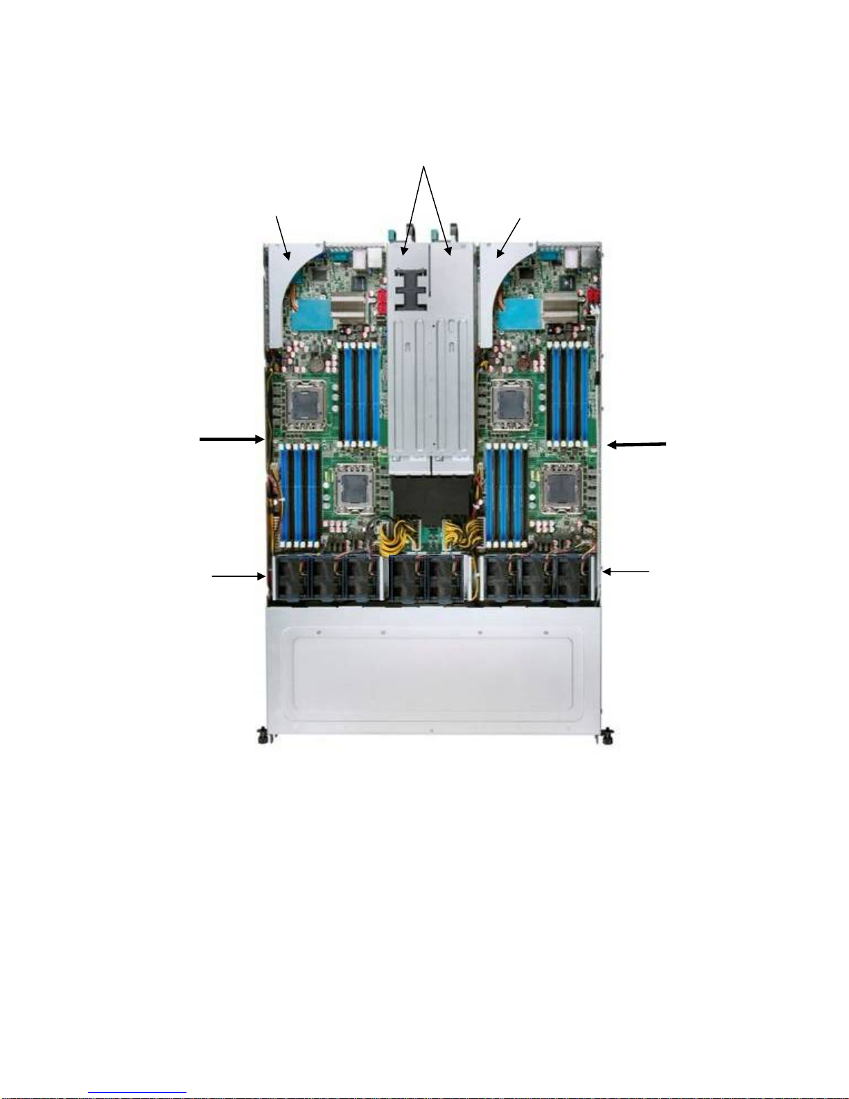
Product Introduction
Power Supply
Server Node
1
4 x System
Fans
Node 1
Riser
Card
Riser
Card
Server Node
2
4 x System
Fans
Node 2
Hard Disk Drive Bay Module
Figure 3. System Component Identification
The following figure identifies connectors and major components of each server node.
4 Intel
®
Server System SR1670HV Service Guide
Page 20
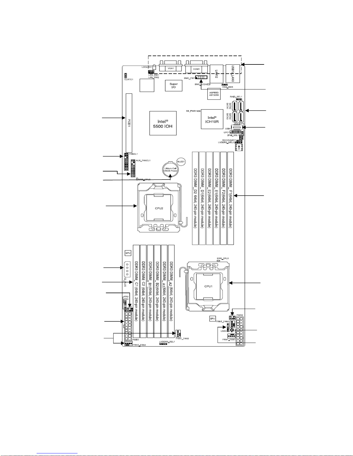
Product Introduction
A
C
B
Q
D
P
O
N
K
M
L
G
H
I
Figure 4. Server Node Connectors and Components
E
F
G
H
I
J
®
Intel
Server System SR1670HV Service Guide 5
Page 21
Product Introduction
Table 3. Server Node Connectors and Components Descriptions
A Rear I/O Connectors K CPU 1 DIMM Slots (Slots A1– C2)
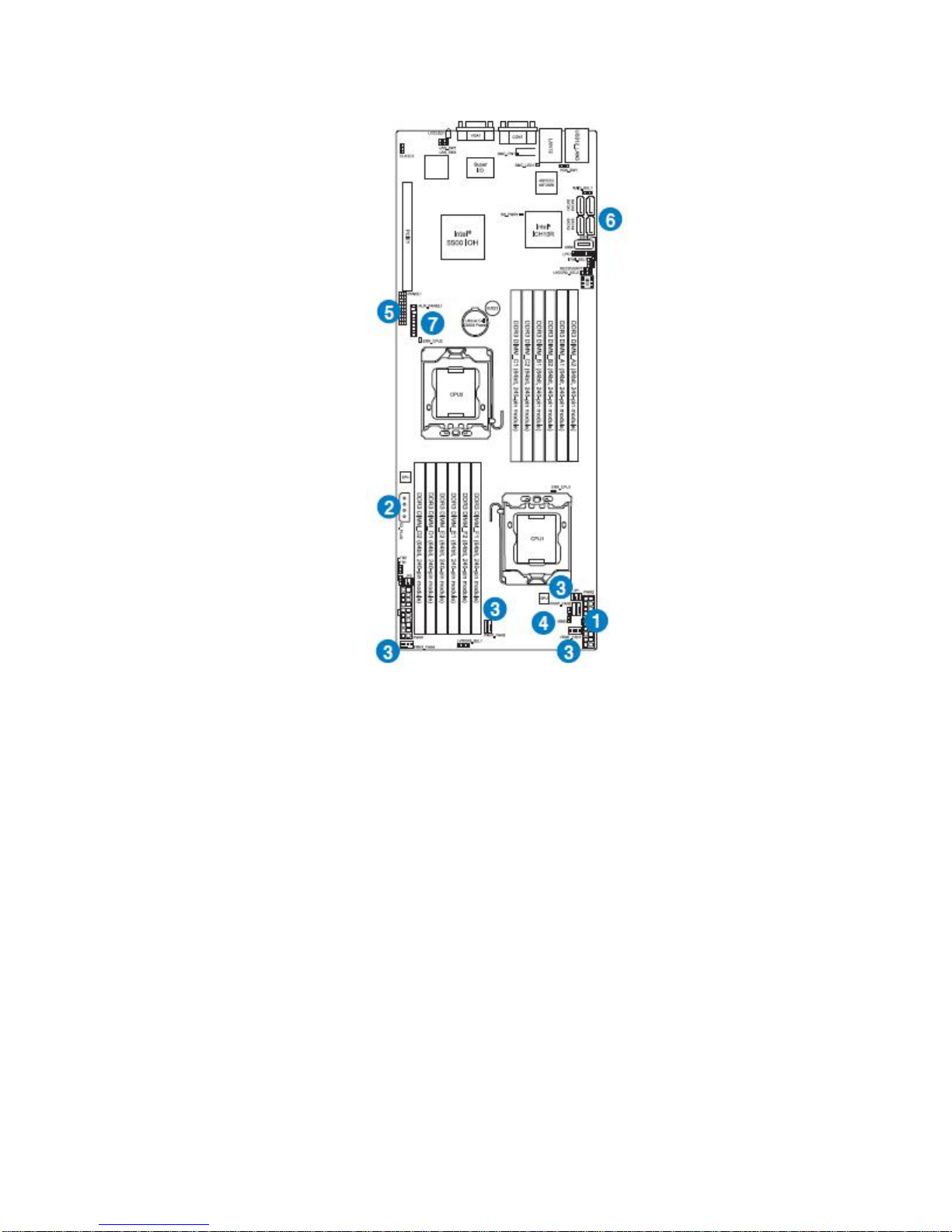
B BMC Management Module connector L Peripheral Drive Power Connector – 4 pin
C SATA Ports 1-4 M CPU 2 - LGA 1366 Socket
D Internal USB(4) 2.0 Port N CMOS Battery
E CPU 2 DIMM Slots (Slots D1 – F2) O Auxilary Front Panel Header
F CPU 1 - LGA 1366 Socket P Front Panel Header
G Power Supply SMBus - 2x3 Pin Header Q X16 GEN 2 PCI Express* Riser Card Slot
H Main Po wer Conn ector – 20 pin
I System Fan Connectors
J USB(3) 2.0 - 1x5 Pin Header
Description Description
1.6 System LED Information
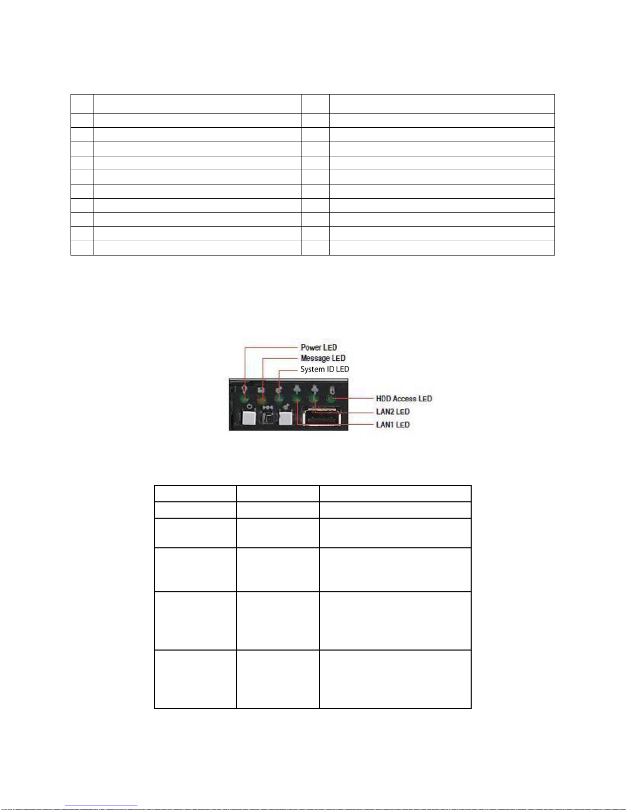
1.6.1 Front Control Panel LEDs
Figure 5. Front Control Panel LEDs
Table 4. Front Panel LEDs Descriptions
LED Display Status Description
Power LED
HDD Activity
Message LED
System ID LED
LAN LEDs
ON System power ON
OFF
Blinking
OFF
Blinking
OFF
ON
OFF
Blinking
ON
No activity
Read/write data into the HDD.
System is normal; no incoming
event.
Indicates a HW monitor event.
Normal status
Location switch is pressed (Press
the location switch again to turn
off). BMC reset in progress when
re-plug Power cord
No LAN connection
LAN is transmitting or receiving
data.
LAN connection is present.
6 Intel
®
Server System SR1670HV Service Guide
Page 22
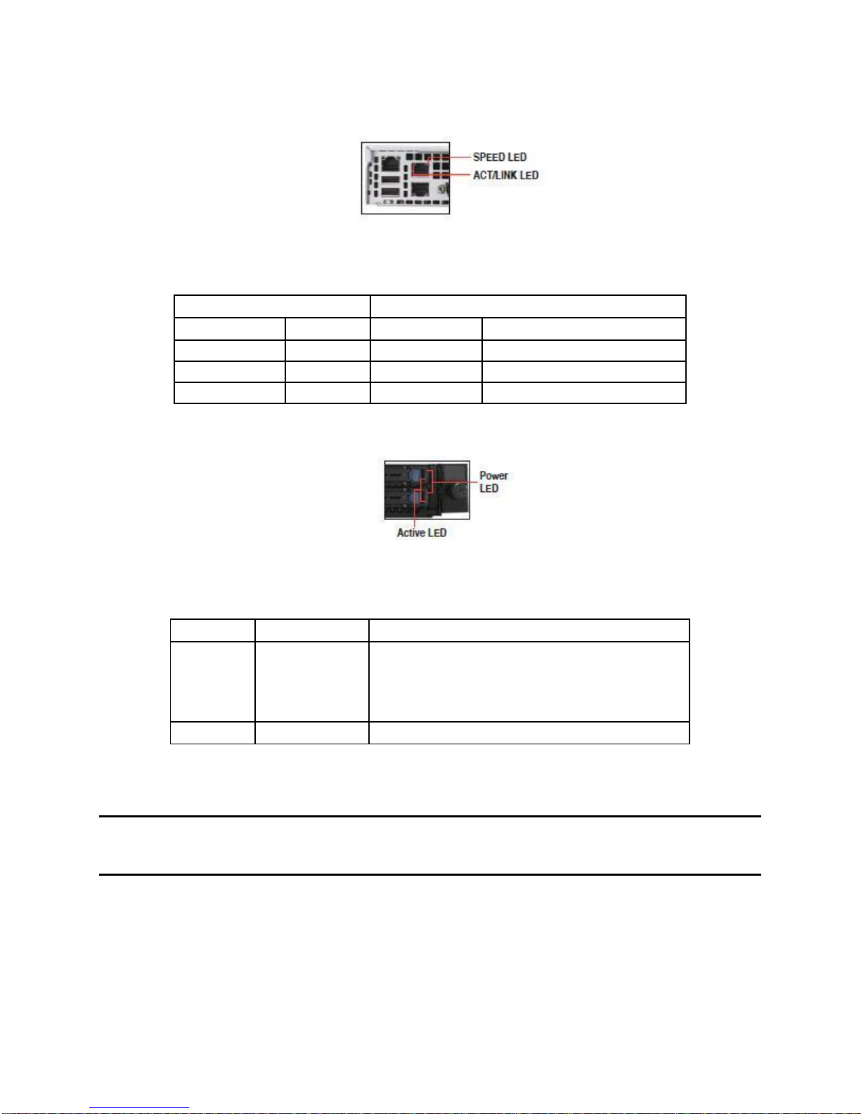
1.6.2 RJ-45 LAN Ports 1 and 2 LEDs
Figure 6. RJ-45 Ports 1 and 2 LEDs
Table 5. RJ-45 Ports 1 and 2 LEDs Descriptions
ACT/LINK LED SPEED LED
Status Description Status Description
OFF No link OFF 10 Mbps connection
GREEN Linked Orange 100 Mbps connection
BLINKING Data activity Green 1 Gbps connection
1.6.3 HDD Status LED
Product Introduction
Figure 7. HDD Status LED
Table 6. HDD LED Status Definitions
LED Status Description
Power
Active
Green Light ON
Red Light ON
G/R Blinking
OFF
Green Blink Data read/write to HDD
Power On (detection HDD present)
RAID HDD fail (HDD plug-in ready but detection error)
RAID rebuilding
HDD not found
1.7 Cable Connections
NOTE: The bundled system cables are pre-connected before shipment. You do not need to
disconnect these cables unless you must remove pre-installed components for servicing or to
install additional devices.
Refer to Chapter 4, “System Service” for detailed information on the
connections.
®
Intel
Server System SR1670HV Service Guide 7
Page 23
Product Introduction
Figure 8. Cable Connections
1.7.1 Pre-Connected System Cables
1. 20-pin Main Power connector (from power supply to server board)
2. 4-pin Peripheral Power connector (from server board to add-in peripheral device)
3. System Fan connectors (from server board to system fans)
4. USB connector (from server board to front control panel)
5. Front Control Panel connector (from server board to front control panel)
6. SATA connectors (from server board to backplane)
7. Auxiliary Panel connector (from server board to front control panel)
8 Intel
®
Server System SR1670HV Service Guide
Page 24
2. Hardware Setup
2.1 Chassis Cover
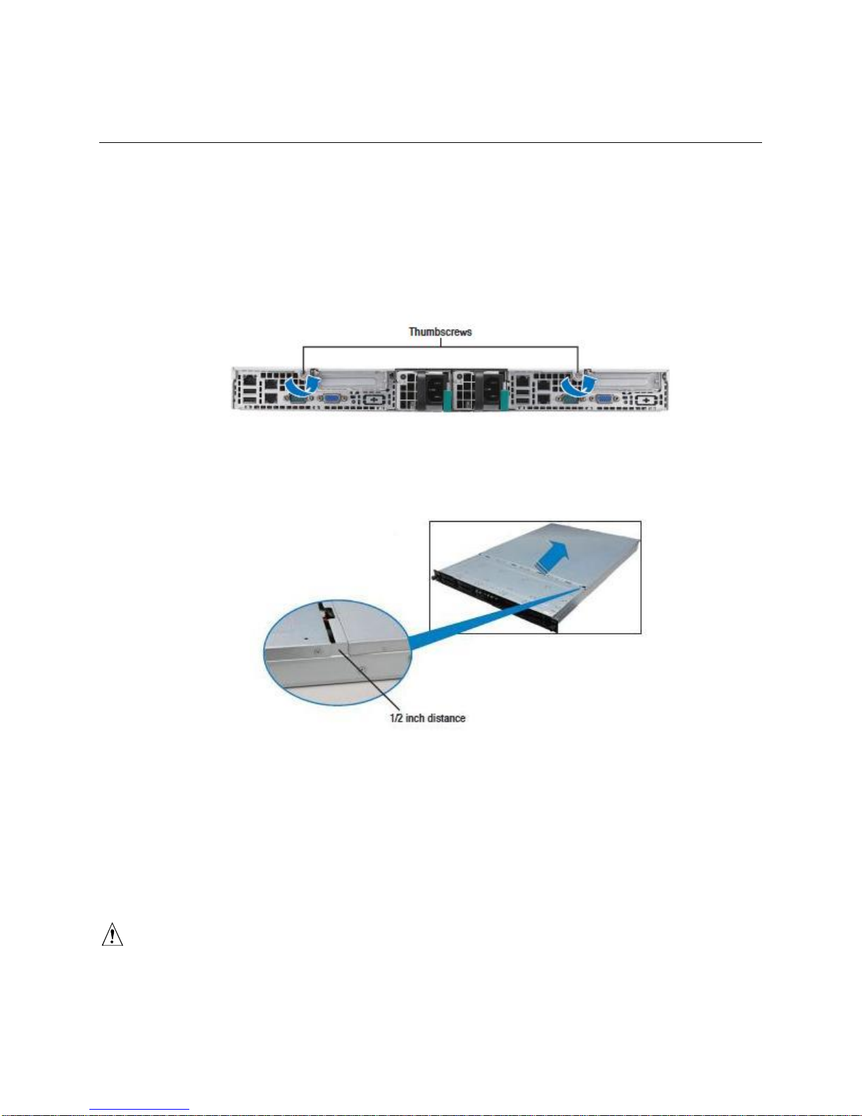
2.1.1 Removing the Chassis Cover
1. Loosen the two thumbscrews on the read panel to release the rear cover from the
chassis.
Figure 9. Rear Panel Thumbscrews
Hardware Setup
2. Firmly hold the cover and slide it toward the rear panel for about half an inch until
disengages from the chassis.
Figure 10. Sliding the Chassis Cover
3. Lift the cover from the chassis.
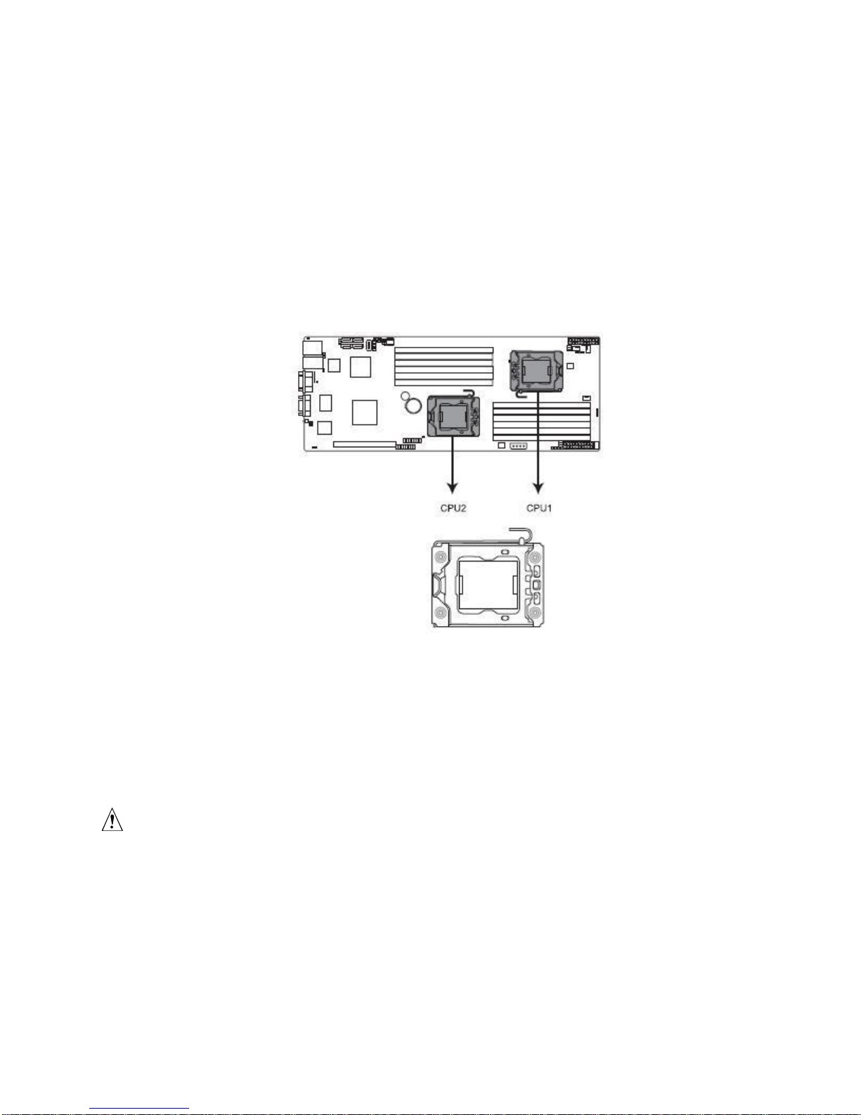
2.2 Central Processing Unit (CPU)
Each installed server node provides two surface mount LGA 1366 CPU sockets designed
for the Intel
®
Xeon® Processor 5500 series and 5600 series.
CAUTIONS
Upon purchase of the server board, ensure the PnP caps are installed
on each processor socket and the socket contacts are not bent. Contact
®
Intel
Server System SR1670HV Service Guide 9
Page 25
Hardware Setup
your retailer immediately if the PnP cap is missing, or if you see any
damage to the PnP cap/socket contacts/server board components.
The PnP cap should be retained and re-used if the server is ever returned for service.
The product warranty does not cover damage to the socket contacts
resulting from incorrect processor installation/removal, or
misplacement/loss/incorrect removal of the PnP cap.
2.2.1 Installing the Processor
To install a processor:
1. Locate the processor socket on the server board.
Figure 11. LGA1366 Socket
TIP
Before installing the processor, ensure the socket box is facing
towards you and the load lever is on your left.
2. Press the load lever with your thumb (A), then move it to the left (B) until it is released
from the retention tab.
CAUTION
To prevent damage to the socket pins, do not remove the PnP cap
unless you are installing a processor.
10 Intel
®
Server System SR1670HV Service Guide
Page 26
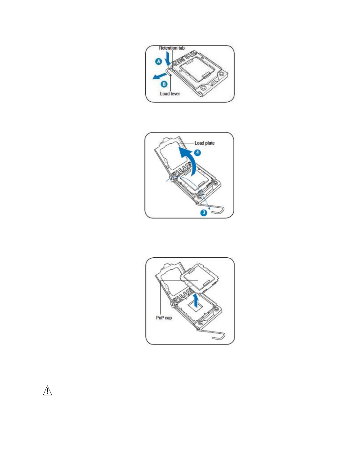
Figure 12. Retention Tab and Load Lever
3. Lift the load lever in the direction of the arrow to a 135° angle.
Hardware Setup
Figure 13. Load Plate
4. Lift the load plate with your thumb and forefinger to a 100° angle.
5. Remove the PnP cap from the processor socket.
Figure 14. PnP Cap
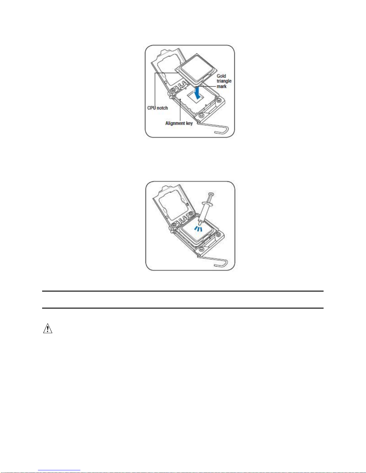
6. Position the processor over the socket, making sure the gold triangle is on the bottomleft corner of the socket, and then fit the socket alignment key into the processor notch.
CAUTION
The processor fits in only one correct orientation. DO NOT force the
processor into the socket to prevent bending the connectors on the
socket and damaging the processor!
®
Intel
Server System SR1670HV Service Guide 11
Page 27
Hardware Setup
Figure 15. CPU Notch and Alignment Key
7. (Skip this step if your heatsink has pre-applied thermal interface material.) Apply
several drops of thermal paste to the exposed area of the processor the heatsink will
be in contact with, ensuring it is spread in an even, thin layer.
Figure 16. Applying Thermal Paste
NOTE: The processor fits in only one correct orientation. DO NOT force the processor into the
socket to prevent bending the connectors on the socket and damaging the processor!
WARNING
The thermal paste is toxic and inedible. If it gets in your eyes or
touches your skin, you must wash it off immediately and seek
professional medical help.
TIP
To prevent contaminating the paste, DO NOT spread the paste with
your finger directly.
8. Close the load plate (A), and then push the load lever (B) until it snaps into the
retention tab.
12 Intel
®
Server System SR1670HV Service Guide
Page 28
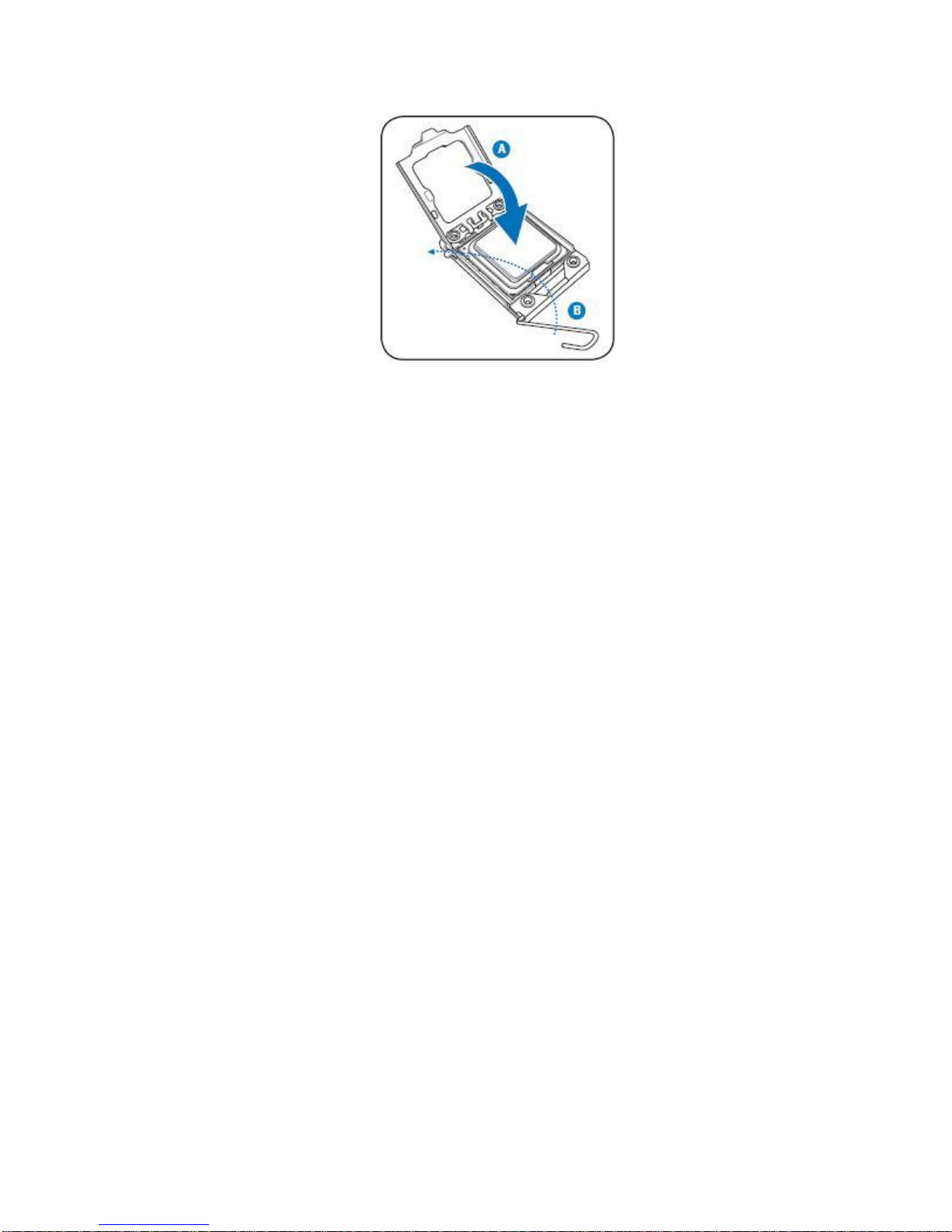
Figure 17. Closing the Load Plate
2.2.2 Installing the Processor Heatsink
You must install the processor before installing the heatsink.
Hardware Setup
Improper installation can damage the heatsink. Pay close attention to the steps and
perform each step exactly as indicated to avoid damage.
The heatsink has Thermal Interface Material (TIM) located on the bottom of it. Use caution
when you unpack the heatsink so you do not damage the TIM.
New unused heatsinks have adequate TIM on the bottom. If you are reusing a heatsink,
make sure there is adequate TIM present on the heatsink to support processor cooling.
To install the heatsink, follows these steps:
1. Remove the protective film on the TIM if present.
2. Orient the heatsink over the processor as shown. You must position the heatsink fins
as shown (Figure 18) to provide correct airflow through the system.
3. Set the heatsink over the processor, lining up the four captive screws with the four
posts surrounding the processor.
4. Loosely screw in the captive screws on the heatsink corners in a diagonal manner
according to the numbers shown (Figure 18) as follows:
a. Starting with the screw at location 1, engage the screw threads by giving it two
rotations in the clockwise direction and stop. (IMPORTANT: Do not fully tighten.)
b. Proceed to the screw at location 2 and engage the screw threads by giving it two
rotations and stop.
c. Engage screws at locations 3 and 4 by giving each screw two rotations and then
stop.
5. Repeat steps 4a through 4c by giving each screw two rotations each time until all
screws are lightly tightened up to a maximum of 8 inch-pounds torque.
®
Intel
Server System SR1670HV Service Guide 13
Page 29

Hardware Setup
2
TIM
Chassis Front
3
Air Flow
4
1
AF002841
Figure 18. Installing the Heatsink (Passive Heatsink Shown)
2.2.3 Removing the Processor Heatsink
To remove or replace a processor, you must first remove the heatsink.
CAUTION
Improper removal can damage the heatsink. Pay close attention to the
steps and perform each step exactly as indicated to avoid damage.
To remove the heatsink, follow these steps:
1. Loosen the four captive screws on the heatsink corners in a diagonal manner
according to the numbers shown in Figure 19 as follows:
a. Starting with the screw at location 1, loosen it by giving it two rotations in the
counter-clockwise direction and stop. (IMPORTANT: Do not loosen fully.)
b. Proceed to the screw at location 2 and loosen it by giving it two rotations and stop.
c. Loosen screws at locations 3 and 4 by giving each screw two rotations and then
stop.
d. Repeat steps 3a through 3c by giving each screw two rotations each time until you
loosen all screws.
2. Twist the heatsink slightly to break the seal between the heatsink and the processor.
3. Lift the heatsink from the processor. If it does not pull up easily, twist the heatsink
again. Do not force the heatsink from the processor. Doing so could damage the
processor.
14 Intel
®
Server System SR1670HV Service Guide
Page 30
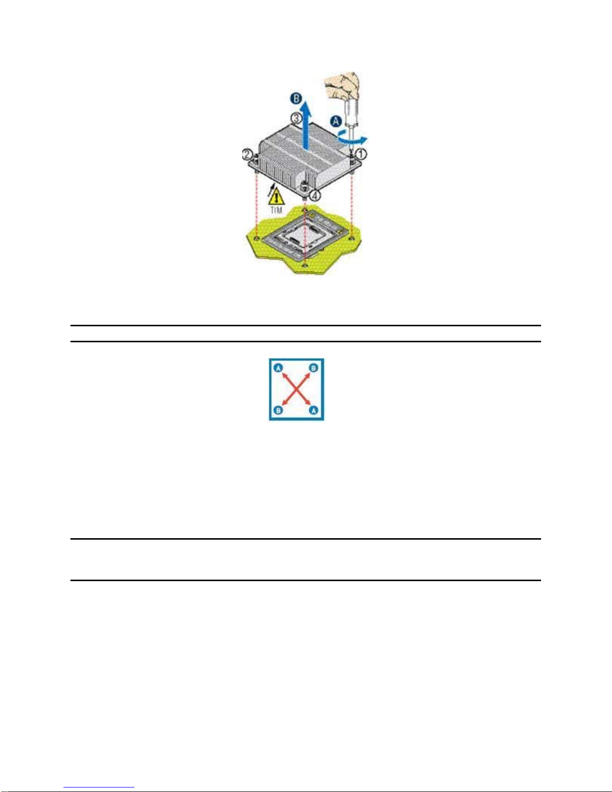
Figure 19. Removing the Heatsink
Hardware Setup
NOTE: Tighten the four heatsink screws in a diagonal sequence.
2.3 System Memory
2.3.1 Overview
Each installed server node supports twelve (12) DDR3 DIMM sockets—six for each
installed processor.
NOTE: You should only install memory in DIMM sockets DIMM_D1 through DIMM_F2 when
dual processors are installed on a given server node. On a given server node, DIMM sockets
DIMM_D1 through DIMM_F2 are not enabled in single processor configurations.
The following figure illustrates the location of the DDR3 DIMM sockets.
®
Intel
Server System SR1670HV Service Guide 15
Page 31

Hardware Setup
Figure 20. DDR3 DIMM Sockets Location
2.3.2 Memory Support
Supported memory follows the DDR3 specification and meets the following characteristics:
800 MHz, 1066 MHz or 1333 MHz operating frequencies
Single-rank (SR), dual-rank (DR), and quad-rank (QR)
Registered DIMM (RDIMM) or Unbuffered DIMM (UDIMM)
RDIMMs must be ECC only
UDIMMs can be ECC or non-ECC and can be mixed within a common
configuration
The Channel Independent mode is the only memory RAS mode that supports
non-ECC DIMMs.
The presence of a single non-ECC UDIMM results in the disabling of ECC
functionality.
RDIMMs and UDIMMs cannot be mixed within a common system memory
configuration
The following table shows the maximum memory amounts using RDIMM type memory:
Table 7. Maximum Memory Allocation Using RDIMMs
Single Rank RDIMMs
800 MHz and 1066 MHz
Dual Rank RDIMMs
800 MHz and 1066 MHz
Quad Rank RDIMMs (1)
800 MHz only
48 GB
(12x 4GB DIMMs)
96 GB
(12x 8GB DIMMs)
96 GB
(12x 8GB DIMMs)
NOTE: Due to thermal requirements needed to support Quad Rank x4 DDR3 DIMMs, the Intel®
Server System SR1670HV does not support this memory type.
16 Intel
®
Server System SR1670HV Service Guide
Page 32

2.3.2.1.1 Memory Population Rules
DIMM population requirements are dependent upon the number of slots per channel;
number of DIMMs installed; and rank type. When installing memory, consider the
following:
Populate DIMMs by channel starting with the blue slot farthest from the CPU.
All channels in a system will run at the fastest common frequency.
RDIMMs and UDIMMs cannot be mixed.
If two 1333 MHz-capable UDIMMs or RDIMMs is detected in the same channel, the
BIOS will flag this as a warning and force the speed down to 1066 MHz.
Table 8. Supported RDIMM Configurations
Hardware Setup
DIMM Slots
per Channel
2 1 Registered
2 1 Registered
2 2 Registered
2 2 Registered
DIMMs Populated
per Channel
DIMM Type Speeds Ranks per
DDR3 ECC
DDR3 ECC
DDR3 ECC
DDR3 ECC
800,
1066,
1333
800, 1066 QR Only
800, 1066 Mixing SR,
800 Mixing SR,
SR or DR
DR
DR, QR
Population Rules
DIMM
1. Any combination of x4 and x8
RDIMMs with 1Gb or 2Gb DRAM
density
Does NOT support 256 Mb, 512 Mb, and 4 Gb DRAM technologies and x16 DRAM on
RDIMM.
If a quad-rank RDIMM is mixed with a single-rank or dual-rank DIMM on a given
channel, you must populate the quad-rank DIMM in the lowest numbered slot.
Table 9. Supported UDIMM Configurations
DIMM
Slots per
Channel
2 1 Unbuffered DDR3
2 2 Unbuffered DDR3
DIMMs
Populated
per Channel
DIMM Type Speeds Ranks per DIMM Population Rules
1. Any combination of x8 UDIMMs
with 1 Gb or 2 Gb DRAM Density
(with or without
ECC)
(with or without
ECC)
800,
1066,
1333
800,
1066
SR or DR
Mixing SR, DR
Does NOT support 256 Mb, 512 Mb, and 4 Gb DRAM technologies; x4 DRAM on
UDIMM and quad-rank UDIMM
Mixing ECC and non-ECC UDIMMs anywhere on the platform forces the system to run
in non-ECC mode.
No RAS support for non-ECC UDIMMs.
No x4 SDDC support with UDIMM with ECC; however, x8 SDDC is supported in lock
step mode with x8 UDIMMs with ECC.
NOTE: Although non-ECC memory can be used in this server system, Intel does not plan to
validate them and strongly discourages their use in a working server environment.
®
Intel
Server System SR1670HV Service Guide 17
Page 33

Hardware Setup
When installing DIMMs, you must follow the following population rules to deliver the best
performance:
Maximize number of channels populated first
Balanced DIMM population across channels and sockets.
Table 10. Memory Population Table
CPU 1 Configuration
DIMM_A2 DIMM_A1 DIMM_B2 DIMM_B1 DIMM_C2 DIMM_C1
1 DIMM
2 DIMMs
3 DIMMs
4 DIMMs
6 DIMMs
DIMM_D2 DIMM_D1 DIMM_E2 DIMM_E1 DIMM_F2 DIMM_F1
1 DIMM
2 DIMMs
3 DIMMs
4 DIMMs
6 DIMMs
-
-
-
; ;
; ; ; ; ; ;
-
-
-
; ;
; ; ; ; ; ;
;
;
;
CPU 2 Configuration
;
;
;
- - - -
-
-
-
- - - -
-
-
-
;
;
;
;
;
;
- -
-
-
- -
-
-
;
;
;
;
With two processors installed, the system will operate only if the DIMM slots of one
processor are populated. In this case, memory is shared between the two processors.
However, due to the associated latency of this configuration, this is NOT a recommended
operating mode.
You can find additional technical information for the memory sub-system in the Technical
Product Specification (TPS).
2.3.3 Installing a DIMM
CAUTION
Before adding or removing DIMMs or other system components, you
must unplug the power supply. Failure to do so may cause severe
damage to both the server board and the components.
1. Unlock a DIMM socket by pressing the retaining clips outward.
2. Align a DIMM on the socket so the notch on the DIMM matches the break on the
socket.
18 Intel
®
Server System SR1670HV Service Guide
Page 34

Hardware Setup
Figure 21. Unlocked Retaining Clips
TIP
A DIMM is keyed with a notch so that it fits in only one direction. To
avoid damaging the DIMM, DO NOT force a DIMM into a socket.
3. Firmly insert the DIMM into the socket until the retaining clips snap back into place and
the DIMM is properly seated.
Figure 22. Locked Retaining Clips
2.3.4 Removing a DIMM
Follow these steps to remove a DIMM:
1. Simultaneously press the retaining clips on each side of the DIMM outward to
disengage the DIMM from the socket.
Figure 23. DIMM Notch
NOTE: Support the DIMM lightly with your fingers when pressing the retaining clips. The DIMM
might get damaged when it flips out with extra force.
2. Remove the DIMM from the socket.
®
Intel
Server System SR1670HV Service Guide 19
Page 35

Hardware Setup
2.4 Installing a PCI Express* Add-In Card to the Riser
Bracket
The system comes with a riser card bracket for each installed server node. To install a PCI
Express* add-in card, you must remove the bracket assembly from the server using the
following procedure:
To install a PCI Express* add-in card:
1. Firmly hold the riser card bracket, and then pull it up to detach it from the riser slot on
the server board.
Figure 24. Riser Card Bracket
2. Place the riser card bracket on a flat and stable surface, and then remove the screw
from the slot bay.
Figure 25. Removing the Screw from Slot Bay
3. Install a PCI Express* add-in card to the bracket as shown, and then secure the card
with a screw.
4. Press the riser card bracket until the golden connectors completely fit the slot and the
bracket aligns with the rear panel.
20 Intel
Figure 26. PCI Express* x 16 Card
®
Server System SR1670HV Service Guide
Page 36

Figure 27. Pressing Rising Card Bracket for Golden Connectors to Fit
5. If applicable, connect the cable(s) to the card.
Hardware Setup
®
Intel
Server System SR1670HV Service Guide 21
Page 37

Hardware Setup
2.5 Installing the BMC Management Module
Complete the following steps to install the BMC Management Module onto the server
board.
1. Locate the BMC_FW1 header on the server board.
Figure 28. BMC_FW1 Header
2. Orient and press the management card in place.
Figure 29. Orienting the Management Module Card
3. Insert the LAN cable plug into the Server Management LAN port located above the
USB ports.
Figure 30. Server Management LAN Port
NOTE: With the BMC Management Module installed, each time the AC power cord is plugged
into the server, there will be a delay of 45-60 seconds before the server powers on. During this
time, the Blue System ID LED will turn on, and the power button will be disabled. This power on
delay is required to reset the BMC controller on the BMC Management Module. Once the BMC
reset is complete, the System ID LED will turn off, and the power button functionality will be reenabled.
22 Intel
®
Server System SR1670HV Service Guide
Page 38

Hardware Setup
2.6 Hard Disk Drives
The system supports up to eight hot-swap 2.5-inch SATAII/SAS hard disk drives—four for
each installed server node. Each installed hard disk is mounted to a drive tray. When
inserted into a drive bay, the hard drive is blind-mated to a matching connector on a
backplane, which is either cabled to SATA ports on each server node (default) or can be
routed to add-in SAS/SAS RAID cards.
The hard drives for each server node are numbered as follows:
3
2
Figure 31. Hard Disk Drives
4
1
Each drive number corresponds to a matching SATA port number on the server board.
To install a hard drive:
1. Release the drive tray by pushing the spring lock to the right, and then pulling the tray
lever outward. The drive tray ejects slightly after you pull out the lever.
2. Firmly hold the tray lever and pull the drive tray out of the bay.
Figure 32. Releasing the Drive Tray
3. Place a SATAII/SAS hard disk drive on the tray, and then secure it with its four screws.
Figure 33. Placing a SATAII/SAS Hard Disk Drive on the Tray
4. Carefully insert the drive assembly into a drive bay until contact is made with the
backplane.
5. Push the tray lever in until it clicks and secures the drive tray in place. The drive tray is
correctly placed when its front edge aligns with the bay edge.
®
Intel
Server System SR1670HV Service Guide 23
Page 39

Hardware Setup
Figure 34. Pushing the Tray Lever
6. Repeat Steps 1 through 5 to add additional hard drives to the system.
24 Intel
®
Server System SR1670HV Service Guide
Page 40

Installing the Rackmount Rail Kit
3. Installing the Rackmount Rail Kit
Your rackmount rail kit package contains:
Two pairs of server rails (for the server)
Two pairs of rack rails (for the rack)
Nut-and-bolt type screws
Figure 35. Rackmount Rail Kit Items
Figure 36. Screw positions on the rail
3.1 Attaching the Rails to the Server
To attach the server rails:
1. Attach the front end of the server rail to the side of the chassis, matching each of the
three hooks to the holes on the rail, and then slide the rail towards the front panel until
it locks into place.
®
Intel
Server System SR1670HV Service Guide 25
Page 41

Installing the Rackmount Rail Kit
Figure 37. Attaching the Front End of the Server Rail to Side of Chassis
2. Attach the rear end of the server rail to the side of the chassis, matching each of the
two hooks to the hooks to the holes on the rail, and then slide the rail towards the front
panel until it locks into place.
Figure 38. Sliding the Server Rail
3. Secure the server rail to the side of the chassis with two screws.
Figure 39. Securing the Server Rail With Screws
4. Repeat steps 1 through 3 to attach the second server rail to the other side of the
chassis.
3.2 Attaching the Rack Rails
To attach the rack rails:
1. Select one unit of space (1U) on the rack where you want to install the server system.
2. Install the nuts on the holes of the 1U space on the rack front.
3. Install the nuts on the holes of the 1U space on the corresponding rack rear.
4. Measure the depth of the rack to determine the length of the rack rails.
5. Measure the rack rail when assembled to ensure it fits the rack.
6. Position the rack rail to the 1U space on the rack. Ensure the front end of the rack rail
goes to the front of the rack space.
26 Intel
®
Server System SR1670HV Service Guide
Page 42

Installing the Rackmount Rail Kit
Figure 40. Positioning the Rack Rail to 1U Space on Rack
7. Secure the front end of the rail with two rack screws.
8. Secure the rear end of the rail with two rack screws.
9. Repeat steps 5 through 8 to assemble and attach the second rail.
3.3 Rackmounting the Server
To mount the server to the rack:
1. Align the server rails with the rack rails, and then push the server all the way to the
depth of the rack.
2. Drive a screw on the mounting ear to secure the server in place.
Figure 41. Mounting Ear
®
Intel
Server System SR1670HV Service Guide 27
Page 43

System Service
4. System Service
4.1 Replacing Power Supply Units (PSUs)
Complete the following steps to replace a failed power supply unit (PSU).
NOTE: Installed power supply units (PSUs) provide no power redundancy. A failed PSU will
bring down the respective server node. You can cold-swap the failed PSU while the other power
supply unit is still functional.
To replace the failed PSU:
1. Disconnect the power cord.
2. Hold the PSU lever and press the PSU latch.
Figure 42. Holding and Pressing the PSU Latch
3. Firmly pull the failed PSU out of the server chassis.
Figure 43. Pulling Out the Failed PSU
4. Firmly push the new PSU into the chassis until the latch locks to the server chassis.
Figure 44. Pushing the New PSU Into the Chassis
28 Intel
®
Server System SR1670HV Service Guide
Page 44

4.2 Replacing System Fans
To uninstall the system fans:
CAUTION
Verify the system is powered off before removing any system fan
from the system. The system fans operate at very high speeds
and may cause serious injury.
1. Disconnect the system fan cable from the fan connector on the server board.
System Service
Figure 45. Disconnecting System Fan Cable
2. Lift the fan and set it aside.
Figure 46. Lifting System Fan
3. Repeat Steps 1 and 2 to uninstall other system fans.
To reinstall a system fan:
1. Insert the fan into the fan cage. The airflow directional arrow on the fan side should
point towards the system rear panel.
2. Connect the system fan cable to the fan connector on the server board.
®
Intel
Server System SR1670HV Service Guide 29
Figure 47. Inserting Fan Into the Fan Cage
Page 45

System Service
3. Reinstall the chassis cover. Press down gently on the location above the system fans
to ensure proper fan installation as shown in the following figure.
Figure 48. Restoring the Chassis Cover
4.3 SATA/SAS BackPlane Replacement
The system includes a single SATA/SAS backplane that is mounted to the back side of the
hard disk drive (HDD) bay module. You can replace the backplane replacement by
performing the following procedure:
1. Remove the system top cover.
2. Remove all hard disk drive assemblies from the drive bays.
NOTE: It is important to label each hard drive with the location from which it was taken from.
You must return hard drives to the same place from which they were taken once you complete
the backplane replacement procedure.
3. The HDD bay module is held in place by six screws, three on each side of the
chassis. Remove all six screws.
Figure 49. Screws On Hard Disk Drive Bay Module
4. Slide the HDD bay module forward approximately ½ inch (1.27cm) and lift front
edge of module from alignment guide slots.
Figure 50. Sliding the Hard Disk Drive Bay Module
30 Intel
®
Server System SR1670HV Service Guide
Page 46

System Service
5. Carefully rotate back and place the connected HDD bay module on top of the
system fan assembly so all connected cables and backplane are exposed.
Figure 51. Connected Cables and Backplane Expose
6. Note the location and connector type of each cable you must disconnect from the
backplane. Disconnect all cables from the backplane and remove the bundled
cables from the latched plastic cable holders.
TIP
7. Place the HDD bay module onto a static-free surface.
8. The backplane is fastened to the HDD bay module using 12 screws. Remove all
screws from the backplane.
9. Carefully pull back the backplane to expose the front panel cables connected to
it.
Figure 52. Front Panel Cables
10. Note the location of each of the four front panel cables and disconnect each from
the backplane.
Label each 8-pin x 16-pin cable pair before disconnecting them from
the backplane. Make sure you reconnect each cable pair to the
correct backplane connectors.
11. Unpack the replacement backplane.
12. Reconnect the front panel cable pairs to the correct connectors on the
backplane.
®
Intel
Server System SR1670HV Service Guide 31
Page 47

System Service
13. Carefully reposition the backplane over the guide pins on each side of the hard
14. Securely fasten all 12 screws into the backplane. Be careful not to overtighten
15. Reposition the hard drive bay module over the system fan assembly and
drive bay. Verify that all of the front panel cables are located completely within
the open area behind the backplane.
them.
reconnect all cables to the backplane. Reposition cable bundles within plastic
cable holders.
Figure 53. Cable Bundles in the Hard Disk Drive Bay Module
NOTE: You must reconnect the SATA cables in the following order with the drive bay module
still positioned in an upside down manner on top of the system fan assembly as shown
SATA 1
SATA 2
SATA 4
SATA 3
Figure 54. SATA Cable Connection Order
16. Carefully reposition the hard drive bay module on to the server chassis, such that
the module falls within alignment slots on each side of the chassis.
32 Intel
®
Server System SR1670HV Service Guide
Page 48

Figure 55. Aligning the Module with the Alignment Slots on the Chassis
17. Slide the hard drive bay module back until the screw holes are aligned.
18. Secure the HDD bay module to the chassis using the six screws, three on each
side.
19. Install the hard drives into the same position from which they were removed.
4.4 Front Control Panel Replacement
System Service
The system includes two separate control panels (one for each server node) on the front
of the chassis which are mounted onto a single removable module. In the event a control
panel’s features stop functioning and it is determined it should be replaced with a spare,
you must perform the following procedure.
1. Power down both server modules and remove AC power.
2. Remove the single screw holding the Control Panel Module in place.
Figure 56. Control Panel Module Screw
3. Carefully pull back the Control Panel module until the cables are fully exposed and
accessible.
®
Intel
Server System SR1670HV Service Guide 33
Page 49

System Service
4. Carefully detach each cable pair from both control panel boards.
5. Place the detached Control Panel module onto an anti-static surface.
Figure 57 Control Panel Module Top view
Figure 58 Detached Control Panel Module
6. Take out the faulty Control Panel board by removing the three screws that attach it to
the module tray.
7. Unpack the replacement Control Panel board and place it onto the module tray,
making sure the Control Panel buttons protrude out of the faceplate holes and screw
holes are in alignment with the screw mounts.
8. Using the three screws, fasten the Control Panel board to the module tray. Be careful
not to overtighten them.
9. Turn over the Control Panel Module and place it in front of the Module bay at the
front of the system.
10. Reattach each cable pair to the appropriate Control Panel board.
11. Carefully slide the Control Panel Module back into the module bay until the screw
holes are in alignment.
12. Using the single screw, fasten the Control Panel module to the chassis.
34 Intel
®
Server System SR1670HV Service Guide
Page 50

Jumpers, Connectors, and LEDs
5. Jumpers, Connectors, and LEDs
5.1 Configuration and Support Jumpers
5.1.1 Clear RTC RAM (CLRTC1)
This jumper allows you to clear the Real Time Clock (RTC) RAM in CMOS. You can clear
the CMOS memory of date, time, and system setup parameters by erasing the CMOS
RTC RAM data. The onboard button cell battery powers the RAM data in CMOS, which
includes system setup information such as system passwords.
To erase the RTC RAM:
1. Turn OFF the computer and unplug the power cord.
2. Move the jumper cap from pins 1–2 (default) to pins 2–3. Keep the cap on pins 2–3 for
about 5 to 10 seconds, and then move the cap back to pins 1–2.
3. Plug in the power cord and turn ON the computer.
4. Hold down the <F2> key during the boot process and enter the BIOS setup to re-enter
data.
CAUTION
Except when clearing the RTC RAM, never remove the cap on the
CLRTC jumper default position. Removing the cap causes system
boot failure!
NOTE: If the steps above do not help, remove the onboard battery and move the jumper again
to clear the CMOS RTC RAM data. After the CMOS clearance, reinstall the battery.
Figure 59. Clear RTC RAM
®
Intel
Server System SR1670HV Service Guide 35
Page 51

Jumpers, Connectors, and LEDs
5.1.2 VGA Controller Setting (3-pin VGA_SW1)
This jumper allows you to enable or disable the onboard VGA controller. Set to pins 1–2 to
activate the VGA feature.
Figure 60. VGA Controller Setting
5.1.3 DDR3 Voltage Control Setting (4-pin LVDDR3_SEL1,
LVDDR3_SEL2)
The server board provides DDR3 voltage control jumper blocks for each CPU bank of
memory. These jumper blocks change the voltage level supplied to the DIMM bank, and
should only be changed when low voltage DDR3 DIMMs are installed.
Set to pins 1–2 to select 1.5V BIOS control, pins 2–3 to select 1.2V Force or 3–4 to select
1.35V Force.
CAUTION
Moving these jumpers from their default position may cause
irreparable damage.The use of LV (low voltage) DDR3 DIMMs on this
server board is intended for future use only, and will only be
supported after Intel has validated their functionality. This document
will be updated with full usage information once validation is complete
and tested LV DDR3 DIMMs are added to the Tested Memory List for
this server board.
36 Intel
®
Server System SR1670HV Service Guide
Page 52

Jumpers, Connectors, and LEDs
Figure 61. DDR3 Voltage Control Setting
5.1.4 LAN Controller Setting (3-poin LAN_SW1, LAN_SW2)
These jumpers allow you to enable or disable the onboard Intel® 82574LGigabit LAN
controllers. Set to pins 1-2 to activate the Gigabit LAN feature.
Figure 62. LAN Controller Setting
5.1.5 Intel
®
ICH10R SATA Port SW RAID Setting (3-pin
RAID_SEL1)
This jumper allows you to select the Serial ATA RAID configuration utility to use when you
create disk arrays. Place the jumper caps on pins 1-2 to select the LSI* SATA Software
RAID utility (default); otherwise, place the jumper caps on pins 2-3 to use the Intel
Storage Manager (IMSM)
®
Matrix
®
Intel
Server System SR1670HV Service Guide 37
Page 53

Jumpers, Connectors, and LEDs
®
Figure 63. Intel
ICH10R SATA Port SW RAID Setting
5.1.6 Force BIOS Recovery Setting (3-pin RECOVERY1)
This jumper allows you to quickly update or recover the BIOS settings when it becomes
corrupted.
To update the BIOS:
1. Prepare a USB flash disk that contains the original or latest BIOS for the server
board (XXXXXX.ROM) and the AFUDOS.EXE utility.
2. Set the jumper to pins 2–3.
3. Insert the USB flash and turn on the system to update the BIOS.
4. Shut down the system.
5. Set the jumper back to pins 1-2.
6. Turn on the system.
Figure 64. Force BIOS Recovery Setting
38 Intel
®
Server System SR1670HV Service Guide
Page 54

Jumpers, Connectors, and LEDs
5.2 Server Board Connectors
5.2.1 Serial ATA Connectors (7-pin SATA1, SATA2, SATA3,
SATA4)
Supported by the Intel® ICH10R chipset, these connectors are for the Serial ATA signal
cables for Serial ATA hard disk drives that allow up to 3 Gb/s of data transfer rate.
Figure 65. SATA Connectors
5.2.2 Internal USB Connectors (A-Type USB4; 5x1 pin USB3)
These connectors are for USB 2.0 ports. Connect the USB module cables to connectors
USB3, and then install the modules to a slot opening at the back of the system chassis.
These USB connectors comply with USB 2.0 specification which supports up to 480 Mbps
connection speed.
®
Intel
Server System SR1670HV Service Guide 39
Figure 66. USB 2.0 Connectors
Page 55

Jumpers, Connectors, and LEDs
5.2.3 System Fan Connectors (4-pin FRNT_FAN1, FRNT_FAN2,
FRNT_FAN3, FRNT_FAN4)
The system fan connectors support cooling fans of 350 mA–740 mA (8.88 W max.) or a
total of 3.15 A–6.66 A (53.28 W max.) at +12V. Connect the fan cables to the fan
connectors on the server board, ensuring the black wire of each cable matches the ground
pin of the connector.
CAUTION
DO NOT forget to connect the fan cables to the fan connectors.
Insufficient air flow inside the system may damage the server board
components.
Figure 67. Front Fan Connectors
5.2.4 Serial General Purpose Input/Output Connector (6-1 pin
SGPIO1)
This connector is used for the SGPIO peripherals for the LSI* Software RAID and Intel®
Matrix RAID SATA LED.
Figure 68. Serial General Purpose I/O Connector
40 Intel
®
Server System SR1670HV Service Guide
Page 56

Jumpers, Connectors, and LEDs
5.2.5 BMC Management Module Header (BMC_FW1)
The BMC connector on the server board supports a BMC Management Module.
Figure 69. BMC Management Module Header
5.2.6 Power Supply SMBus Connectors (6x1 pin JP1, JP2)
These connectors allow you to connect SMBus (System Management Bus) to the power
supply unit to read PSU information. Devices communicate with a SMBus host and/or
other SMBus devices using the SMBus interface.
Figure 70. Power Supply SMBus Connectors
®
Intel
Server System SR1670HV Service Guide 41
Page 57

Jumpers, Connectors, and LEDs
5V
5.2.7 Main Power Connectors (20-pin PWR1, 20-pin PWR2)
The server board provides dual 20-pin ATX Main Power connectors. Both connectors
have identical pin-outs and are not used concurrently.
Figure 71. Main Power Connectors
5.2.8 Peripheral Power Connector (4-pin PWR3)
The server board provides a 4-pin peripheral power connector. This connector can supply
power as needed to add-in peripheral devices such as hard drives or optical drives. This
connector has the following pin-out and board location:
+12 V
GND
GND
+
Figure 72. Peripheral Power Connector (4-pin PWR3)
5.2.9 System Panel Connector (20-pin PANEL1)
This connector supports several chassis-mounted functions.
42 Intel
®
Server System SR1670HV Service Guide
Page 58

Figure 73. System Panel Connector
5.2.9.1 System power LED (3-pin PLED)
Jumpers, Connectors, and LEDs
This 3-pin connector is for the system power LED. Connect the chassis power LED cable
to this connector. The system power LED lights up when you turn on the system power
and blinks when the system is in sleep mode.
5.2.9.2 System Message LED (2-pin MLED)
This 2-pin connector is for the message LED cable that connects to the front message
LED. The message LED is controlled by the hardware monitor to indicate an abnormal
event occurrence.
5.2.9.3 System warning speaker (4-pin SPEAKER)
This 4-pin connector is for the chassis-mounted system warning speaker. The speaker
allows you to hear system beeps and warnings.
5.2.9.4 Hard disk drive activity LED (2-pin HDDLED)
This 2-pin connector is for the HDD Activity LED. Connect the HDD Activity LED cable to
this connector. The IDE LED lights up or flashes when data is read from or written to the
HDD.
5.2.9.5 Power button/soft-off button (2-pin PWRSW)
This connector is for the system power button. Pressing the power button turns the system
on or puts the system in sleep or soft-off mode depending on the BIOS settings. Pressing
the power switch for more than four seconds while the system is ON turns the system
OFF.
5.2.9.6 Reset button (2-pin RESET)
This 2-pin connector is for the chassis-mounted reset button for system reboot without
turning off the system power.
®
Intel
Server System SR1670HV Service Guide 43
Page 59

Jumpers, Connectors, and LEDs
5.2.10 Auxiliary Panel Connector (20-pin AUX_PANEL1)
This connector is for additional front panel features including front panel SMB, locator LED
and switch, chassis intrusion, and LAN LEDs.
Figure 74. Auxiliary Panel Connector
5.2.10.1 Front panel SMB (6-1 pin FPSMB)
These leads connect the front panel SMBus cable.
5.2.10.2 LAN activity LED (2-pin LAN1_LED, LAN2_LED)
These leads are for Gigabit LAN activity LEDs on the front panel.
5.2.10.3 Chassis intrusion (4-1 pin CHASSIS)
These leads are for the intrusion detection feature for chassis with intrusion sensor or
microswitch. When you remove any chassis component, the sensor triggers and sends a
high-level signal to these leads to record a chassis intrusion event. The default setting is
short CASEOPEN and GND pin by jumper cap to disable the function.
5.2.10.4 System ID LED (2-pin LOCATORLED1 and 2-pin
LOCATORLED2)
These leads are for the locator LED1 and LED2 on the front panel. Connect the Locator
LED cables to this 2-pin connector. The LEDs will light up when the Locator button is
pressed.
5.2.10.5 System ID Button/Switch (2-pin LOCATORBTN)
These leads are for the locator button on the front panel. This button queries the state of
the system locator.
44 Intel
®
Server System SR1670HV Service Guide
Page 60

Jumpers, Connectors, and LEDs
5.3 Internal LEDs
5.3.1 Standby Power LED
The server board comes with a standby power LED. The green LED lights up to indicate
that the system is ON, in sleep mode, or in soft-off mode. This is a reminder that you
should shut down the system and unplug the power cable before removing or plugging in
any server board component. The following illustration shows the location of the onboard
LED.
Figure 75. Standby Power LED
5.3.2 CPU Warning LED (ERR_CPU1, ERR_CPU2)
The CPU warning LEDs light up to indicate an impending failure of the corresponding
CPU.
®
Intel
Server System SR1670HV Service Guide 45
Figure 76. ERR CPU LED
Page 61

Jumpers, Connectors, and LEDs
5.3.3 System Identification LED
The server board includes a System ID LED. This LED illuminates when the System ID
button on the front panel is pushed. This LED is used to identify the system when
servicing is required in a racked environment.
Figure 77. System Identification LED
NOTE: The blue system ID LED will turn on when plug power cord until the BMC reset complete.
5.3.4 BMC LED (BMC_LED1)
The server board includes a BMC LED. With the BMC Management Module installed, this
LEDs blinks once per second to indicate the BMC is operating.
Figure 78. BMC LED (BMC_LED1)
46 Intel
®
Server System SR1670HV Service Guide
Page 62

BIOS Updates and Configuration
6. BIOS Updates and Configuration
Your server system includes a BIOS which is used to configure critical system settings,
ensuring best performance and reliability. In addition, it provides options that you can
manually set to configure system features and functions to best meet custom operating
environments. This section describes how to keep your system BIOS up to date, recover
the BIOS in the unlikely event it gets corrupted, and access the BIOS Setup Utility used to
configure many of its options.
6.1 Updating System BIOS
Periodically, Intel makes available a new BIOS release for its server products to enhance
features or correct reported issues. You can download BIOS updates for this server
system from Intel at the following web site:
http://support.intel.com/support/motherboards/server/SR1670HV/
The System Update or BIOS Update package includes the following files:
AFUDOS.EXE – A DOS-based utility used to update the BIOS and provide additional
support options.
xxxxxxxx.ROM – BIOS image file used by the AFUDOS utility.
BIOS##.BAT – DOS Batch file used to update the BIOS by executing the AFUDOS
utility with the appropriate command line options.
README.TXT – Release notes for the BIOS Update describing changes.
NOTE: Prior to updating the System BIOS, Intel recommends reading the Release Notes to fully
understand the changes made to the new release and determine how they may affect your
system after the update in completed.
Before performing the BIOS update, Intel recommends noting all current BIOS Setup options.
These will need to be reset to your desired settings after the BIOS Update has completed. See
the BIOS Setup Utility section later for more information about this utility.
You should complete the following procedure to update the System BIOS:
1. Extract files from the BIOS Update Package to a DOS bootable USB Flash Drive.
2. Plug in the USB Flash Drive and reboot the server to boot from it.
NOTE: With the USB Flash drive plugged in, you may need to access the BIOS Setup Utility to
configure the USB Flash Drive as the first Boot Drive in the system. See BIOS Setup later in this
chapter for instructions on how to access the BIOS Setup utility and make this change.
3. At the DOS prompt, type the name of the batch file <BIOS##.BAT> where ## is the
BIOS revision. The BIOS update begins as soon as the <ENTER> key is pressed.
®
Intel
Server System SR1670HV Service Guide 47
Page 63

BIOS Updates and Configuration
Figure 79. Updating the BIOS in DOS
NOTE: DO NOT turn off the system or interrupt the BIOS update process. Doing so corrupts the
BIOS and prevents your system from booting up. If your BIOS becomes corrupted for any
reason, you must read and complete the BIOS Recovery Process described later in this section.
4. When the BIOS Update has completed successfully, you must reboot the system for the
changes to take effect.
5. During POST, access the <F2> BIOS Setup Utility when prompted.
6. At the Main Menu Screen, press the <F9> key to reset BIOS defaults.
7. Reset any preferred BIOS option settings
8. Save the BIOS Settings and reboot server.
6.2 BIOS Recovery Process
In the unlikely event your system BIOS gets corrupted, you should complete the following
BIOS recovery process:
1. Download the latest BIOS or System Update Package from the following Intel Web
Site
http://support.intel.com/support/motherboards/server/SR1670HV/
2. Extract all the files from the update package to the root directory of a DOS bootable
USB Flash Drive.
3. Remove the system top cover.
4. On the server node with the corrupt BIOS, move the “Force BIOS Update” jumper (as
shown in the following diagram) from pins 1-2 (default) to pins 2-3.
48 Intel
®
Server System SR1670HV Service Guide
Page 64

BIOS Updates and Configuration
Figure 80. Recovering the BIOS Using the Force BIOS Update Jumper
5. Plug in the USB flash drive and power on the system. The BIOS update process
begins automatically.
6. When the BIOS update has completed successfully, power down the system.
7. Set the Force BIOS Update jumper back to its default position.
8. Re-install the system top cover.
9. Power on the system and access the <F2> BIOS Setup utility .
10. Hit the <F9> key to load BIOS Setting Defaults.
11. Reset any preferred BIOS setup options.
12. Save the BIOS Settings and reboot the system.
6.3 BIOS Setup Utility
The server board includes an embedded BIOS Setup Utility that you can use to manually
change various system features and functions to meet the needs of custom operating
environments. This section provides an overview of the following topics:
BIOS Setup Utility Access
BIOS Setup Utility Navigation
BIOS Setup Utility Menu Options Overview
CAUTION
Intel strongly suggests having only qualified persons with in-depth knowledge
of server configuration make changes to BIOS settings. Incorrectly setting
many of the options available can negatively impact the operation of the
server.
Intel recommends using default BIOS settings whenever possible.
®
Intel
Server System SR1670HV Service Guide 49
Page 65

BIOS Updates and Configuration
NOTE: Should the system operate in an undesired manner after making BIOS setting changes,
default settings should be restored by either selecting the “Load Setup Defaults” option in the
Exit Menu, or by hitting the <F9> key anytime while in the BIOS Setup Utility.
6.3.1 Accessing BIOS Setup Utility
The embedded BIOS Setup Utility is accessed by pressing the <F2> key while the system
is conducting its Power-On Self Test (POST). As the system is booting up, the screen will
display when you can access the BIOS Setup Utility.
6.3.2 BIOS Setup Features and Navigation
The BIOS Setup Utility is menu-driven. Each menu screen is divided into different display
and selection areas.
6.3.2.1 Menu Bar
At the top of each menu screen is a Menu Bar that lists the top level Menu Options. To
navigate through the Menu Bar, press the right or left arrow keys until the menu you need
is highlighted and the menu options are displayed. The Menu Bar lists the following top
level menus:
Main: Displays basic system information and provides options to view information and
configure SATA devices attached to the server.
Advanced: Provides several sub-menus used to configure server sub-system features
and functions. Care should be taken when changing options in this section. Making
uninformed changes can alter system behavior to an undesired state.
50 Intel
Figure 81. BIOS Menu Screen
®
Server System SR1670HV Service Guide
Page 66

BIOS Updates and Configuration
Server: Provides sub-menus used to view/change IPMI and Remote Connectivity options.
Boot: Provides sub-menus used to view/change system boot options and system security.
Exit: Provides utility exit options and an option to load BIOS option default settings.
6.3.2.2 Navigation Keys
At the bottom-right corner of a menu screen are the navigation keys for that particular
menu. Use the navigation keys to select items in the menu and change the settings.
6.3.2.3 Menu Items
Each menu option from the Menu Bar displays information, options, and sub-menus
appropriate to the highlighted Menu Bar option. Use the up and down arrow keys to
navigate to the displayed options and sub-menus. A scroll bar displays on the right side of
a menu screen when there are items that do not fit on the screen.
Informational fields are colored in gray. These fields are for informational purposes only
and cannot be changed.
Option Fields are colored in blue. Once highlighted, you can change the option to the
preferred settings by typing in the change or pressing the <Enter Key> which may bring up
a pop-up window, allowing you to select the preferred setting.
Sub-menu fields are colored in blue and are identified by a solid blue triangle before each
sub-menu field descriptor. Highlight the sub-menu you want to view and press the <Enter>
key to display the sub-menu screen.
6.3.2.4 General Help
At the top right corner of the menu screen is a brief description of the selected item.
6.3.3 Main Menu
Upon entering the BIOS Setup Utility, the Main menu screen displays, providing options to
view basic system information and view/configure any SATA devices detected.
®
Intel
Server System SR1670HV Service Guide 51
Figure 82. Pop-Up Window
Page 67

BIOS Updates and Configuration
Figure 83. Main Menu
6.3.3.1 System Time [xx/xx/xxxx]
This option displays and gives the option to change the system time.
6.3.3.2 System Date [Day xx/xx/xxxx]
This option displays and gives the option to change the system date.
6.3.3.3 SATA 1-4 Sub-Menus
These fields display devices that BIOS automatically detected as attached to the on-board
SATA ports. A separate sub-menu is available to view/configure each detected device.
Select a device item, and then press <Enter> to display the device information.
Fields displayed in gray are information that the BIOS has obtained directly from the
device, and may include the following: Device Type, Vendor, Size, LBA Mode, Block
52 Intel
Figure 84. SATA1-4 Submenu
®
Server System SR1670HV Service Guide
Page 68

BIOS Updates and Configuration
Mode, PIO Mode, Async DMA, Ultra DMA, and S.M.A.R.T. monitoring. These values are
not user-configurable. If no device is detected on the selected SATA port, these fields
display N/A.
6.3.3.3.1 LBA/Large Mode [Auto]
Enables or disables the LBA mode. Setting to [Auto] enables the LBA mode if the device
supports this mode, and if the device was not previously formatted with LBA mode
disabled.
Configuration options: [Disabled] [Auto]
6.3.3.3.2 Block (Multi-Sector Transfer) M [Auto]
Enables or disables data multi-sectors transfers. When set to [Auto], the data transfer from
and to the device occurs multiple sectors at a time if the device supports multi-sector
transfer feature. When set to [Disabled], the data transfer from and to the device occurs
one sector at a time.
Configuration options: [Disabled] [Auto]
6.3.3.3.3 PIO Mode [Auto]
Allows you to select the data transfer mode.
Configuration options: [Auto] [0] [1] [2] [3] [4]
6.3.3.3.4 DMA Mode [Auto]
Sets the DMA mode. Configuration options: [Auto] [SWDMA0] [SWDMA1] [SWDMA2]
[MWDMA0] [MWDMA1] [MWDMA2] [UDMA0] [UDMA1] [UDMA2] [UDMA3] [UDMA4]
[UDMA5]
6.3.3.3.5 SMART Monitoring [Auto]
Sets the Smart Monitoring, Analysis, and Reporting Technology.
Configuration options: [Auto] [Disabled] [Enabled]
6.3.3.3.6 32Bit Data Transfer [Enabled]
Enables or disables 32-bit data transfer.
Configuration options: [Disabled] [Enabled]
6.3.3.4 IDE Configuration Sub-Menu
The items in this menu allow you to set or change the configurations for the IDE devices
installed in the system. Select an item then press <Enter> if you want to configure the
item.
®
Intel
Server System SR1670HV Service Guide 53
Page 69

BIOS Updates and Configuration
Figure 85. IDE Configuration Menu
6.3.3.4.1 SATA Configuration [Enhanced]
Configuration options: [Disabled] [Compatible] [Enhanced]
Configure SATA as [IDE]
Sets the configuration for the Serial ATA connectors supported by the Southbridge chip.
Configuration options: [IDE] [RAID] [AHCI]
TIPS
If you want to use the Serial ATA hard disk drives as Parallel ATA physical
storage devices, keep the default setting [IDE].
If you want the Serial ATA hard disk drives to use the Advanced Host
Controller Interface (AHCI), set this item to [AHCI]. The AHCI allows the
onboard storage driver to enable advanced Serial ATA features that
increases storage performance on random workloads by allowing the
drive to internally optimize the order of commands.
®
If you want to use LSI*Software RAID or the Intel
Matrix Storage
Technology configuration from the Serial ATA hard disk drives, set this
item to [RAID].
6.3.3.4.2 Hard Disk Write Protect [Disabled]
Disables or enables device write protection. This is effective only if the device is accessed
through the BIOS.
Configuration options: [Disabled] [Enabled]
6.3.3.4.3 IDE Detect Time Out (Sec) [35]
Selects the time out value for detecting ATA/ATAPI devices.
Configuration options: [0] [5] [10] [15] [20] [25] [30] [35]
6.3.3.5 AHCI Configuration Sub-Menu
This menu is the section for AHCI configuration.
54 Intel
®
Server System SR1670HV Service Guide
Page 70

Figure 86. AHCI Configuration Menu
6.3.3.5.1 AHCI CD/DVD Boot Time out [35]
Selects the boot time out value for SATA CD/DVD devices in AHCI mode.
Configuration options: [0] [5] [10] [15] [20] [25] [30] [35]
6.3.3.5.2 SATA Port1-4 [XXXX]
Displays the status of auto-detection of SATA devices.
BIOS Updates and Configuration
Figure 87. Status of Auto-Detection of SATA Devices Menu
6.3.3.5.3 SATA Port0 [Auto]
Allows you to select the type of device connected to the system.
Configuration options: [Auto] [Not Installed]
6.3.3.5.4 SMART Monitoring [Enabled]
Allows you to set the Self-Monitoring, Analysis and Reporting Technology.
Configuration options: [Disabled] [Enabled]
®
Intel
Server System SR1670HV Service Guide 55
Page 71

BIOS Updates and Configuration
6.3.3.6 System Information Sub-Menu
This menu gives you an overview of the general system specifications. The BIOS
automatically detects the items in this menu.
Figure 88. System Information Menu
OS SETUP UTILITY
6.3.3.6.1 AMIBIOS
Displays the auto-detected BIOS information.
6.3.3.6.2 Processor
Displays the auto-detected processor information.
6.3.3.6.3 System Memory
Displays the total system memory detected.
6.3.3.6.4 LAN# Address
Displays the MAC Address assigned to on-board LAN Ports 1 and 2
6.3.3.6.5 System Memory Information
Sub-Menu option that provides information for each detected DIMM attached to
Processors 1 and 2. Information provided for each installed DIMM includes: Slot ID, size,
rank, speed, and current operating temperature.
56 Intel
Figure 89. System Memory Information Menu
®
Server System SR1670HV Service Guide
Page 72

BIOS Updates and Configuration
6.3.4 Advanced Menu
The Advanced menu items are used to view/change server sub-system options.
CAUTION
Intel strongly suggests having only qualified persons with in-depth knowledge
of processor and chipset features make changes to the options available in
the Advanced Menu. Incorrectly setting many of the options available within
these sub-menus can negatively impact the operation of the server.
Intel recommends using default settings whenever possible.
If the system operate in an undesired manner after making BIOS setting
changes, you should restore default settings by either selecting the “Load
Setup Defaults” option in the Exit Menu, or pressing the <F9> key anytime
while in the BIOS Setup Utility.
6.3.4.1 CPU Configuration Sub-Menu
The items in this menu display the CPU-related information that the BIOS automatically
detects. Some items may not display if your CPU does not support the related functions.
®
Intel
Server System SR1670HV Service Guide 57
Figure 90. Advanced Menu
Page 73

BIOS Updates and Configuration
Scroll down for more items.
Figure 91. CPU Configuration Menu
Figure 92. CPU Configuration Menu, Continued
6.3.4.1.1 C1E Support [Enabled]
Allows you to enable or disable Enhanced Halt State support.
Configuration options: [Disabled] [Enabled]
6.3.4.1.2 Hardware Prefetcher [Enabled]
Allows you to enable or disable the Hardware Prefetcher function.
Configuration options: [Disabled] [Enabled]
6.3.4.1.3 Adjacent Cache Line Prefetch [Enabled]
Allows you to enable or disable the Adjacent Cache Line Prefetch function.
Configuration options: [Disabled] [Enabled]
58 Intel
®
Server System SR1670HV Service Guide
Page 74

BIOS Updates and Configuration
6.3.4.1.4 Intel® Virtualization Tech [Enabled]
®
The Intel
Virtualization Technology allows a hardware platform to run multiple operating
systems separately and simultaneously, enabling one system to virtually function as
several systems.
Configuration options: [Disabled] [Enabled]
6.3.4.1.5 CPU TM Function [Enabled]
This function enables the overheated CPU to throttle the clock speed to cool down.
Configuration options: [Disabled] [Enabled]
6.3.4.1.6 Execute-Disable Bit Capability [Enabled]
Allows you to enable or disable the No-Execution Page Protection Technology. Setting
this item to [Disabled] forces the XD feature flag to always return to zero (0).
Configuration options: [Disabled] [Enabled]
®
6.3.4.1.7 Intel
Allows you to enable or disable the Intel
HT Technology [Enabled]
®
Hyper-Threading Technology function. When
disabled, only one thread per activated core is enabled.
Configuration options: [Enabled] [Disabled]
6.3.4.1.8 Active Processor Cores [All]
Allows you to select the number of CPU cores to activate in each processor package.
Configuration options: [All] [1] [2]
6.3.4.1.9 A20M [Disabled]
Legacy operating systems and APs may need A20M enabled.
Configuration options: [Disabled] [Enabled]
6.3.4.1.10 DCU Mode [32KB 8-way without]
Allows you to select the mode for the Data Cache.
Configuration options: [32KB 8-way without ECC] [16KB 4-way with ECC]
6.3.4.1.11 DCA Prefetch Delay [32]
Allows you to select the time delay in bus clocks from snoop to prefetch.
Configuration options: [8] [16] [24] [32] [40]—[104] [112] [120]
®
6.3.4.1.12 Intel
SpeedStep (TM) Tech [Enabled]
When set to [Disabled], the CPU runs at its default speed. When set to [Enabled], the CPU
speed is controlled by the operating system.
Configuration options: [Disabled] [Enabled]
6.3.4.1.13 Intel TurboMode Tech [Enabled]
When enabled, Turbo Mode allows processor cores to run faster than its marked
frequency in certain conditions.
®
Intel
Server System SR1670HV Service Guide 59
Page 75

BIOS Updates and Configuration
Configuration options: [Disabled] [Enabled]
®
6.3.4.1.14 Intel
®
The Intel
C-State Technology allows the CPU to save more power under idle mode.
C-STATE Tech [Enabled]
Enable this item only when you install a C-State Technology-supported CPU.
Configuration options: [Disabled] [Enabled]
6.3.4.1.15 C3 State [ACPI C3]
Allows you to select the CPU action under C3 state.
Configuration options: [Disabled] [ACPI C2] [ACPI C3]
6.3.4.1.16 C6 State [Enabled]
Allows you to select the CPU action under C6 state.
Configuration options: [Disabled] [Enabled]
6.3.4.1.17 C State package limit setting [Auto]
This item displays only when you set the Intel(R) C-STATE Tech item to [Enabled]. We
recommend that you set this item to [Auto] for BIOS to automatically detect the C-State
mode supported by your CPU.
Configuration options: [Auto] [C1] [C3] [C6] [C7]
6.3.4.1.18 C1 Auto Demotion [Enabled]
When enabled, the processor conditionally demotes C3/C6/C7 requests to C1 based on
on-core auto-demote information.
Configuration options: [Disabled] [Enabled]
6.3.4.1.19 C3 Auto Demotion [Enabled]
When enabled, the processor conditionally demotes C6/C7 requests to C3 based on oncore auto-demote information.
Configuration options: [Disabled] [Enabled]
6.3.4.2 Chipset Configuration Sub-Menu
The Chipset configuration menu allows you to change advanced chipset settings. Select
an item then press <Enter> to display the sub-menu.
60 Intel
®
Server System SR1670HV Service Guide
Page 76

BIOS Updates and Configuration
Figure 93. Chipset Configuration Menu
6.3.4.3 CPU Bridge Chipset Configuration Sub-Menu
Figure 94. CPU Bridge Chipset Configuration Menu
Scroll down for more items.
®
Intel
Server System SR1670HV Service Guide 61
Page 77

BIOS Updates and Configuration
Figure 95. CPU Bridge Chipset Configuration Menu, Continued
6.3.4.3.1 CSI Links Speed [Full-Speed]
Allows you to set the speed of CSI Links.
Configuration options: [Slow-Mode] [Full-Speed]
6.3.4.3.2 CSI Frequency [Auto]
Allows you to set the CSI frequency.
Configuration options: [Auto] [4.800GT] [5.866GT] [6.400GT]
6.3.4.3.3 CSI Isochronous [Disabled]
Configuration options: [Disabled] [Enabled]
6.3.4.3.4 CSI L0s [Disabled]
Configuration options: [Disabled] [Enabled]
6.3.4.3.5 CSI L1 [Enabled]
Configuration options: [Disabled] [Enabled]
6.3.4.3.6 CSI Power Optimization Policy [Static]
Configuration Options: [Adaptive] [Static] [Bypass]
6.3.4.3.7 Memory Frequency [Auto]
You may allow the system to detect DDR3 memory frequency via SPD or designate a
specific frequency.
Configuration options: [Auto] [Force DDR-800] [Force DDR-1066] [Force DDR-1333]
6.3.4.3.8 Memory Mode [Independent]
Allows you to set Memory channel mode.
Configuration options: [Independent] [Channel Mirroring] [Lockstep] [Sparing]
6.3.4.3.9 Memory ECC Function [Enabled]
Allows you to enable or disable Memory ECC function.
Configuration options: [Disabled] [Enabled]
6.3.4.3.10 Double Rate Refresh [Auto]
Configuration options: [Disabled] [Auto]
62 Intel
®
Server System SR1670HV Service Guide
Page 78

6.3.4.3.11 Demand Scrubbing [Enabled]
Enables or disables the ECC demand scrub.
Configuration options: [Disabled] [Enabled]
6.3.4.3.12 Patrol Scrubbing [Disabled]
Enables or disables the ECC patrol scrub.
Configuration options: [Disabled] [Enabled]
6.3.4.3.13 NUMA Aware [Auto]
Configuration options: [Disabled] [Enabled]
6.3.4.3.14 Page Policy [Closed]
Configuration options: [Closed] [Open]
6.3.4.3.15 Adaptive Page [Disabled]
Configuration options: [Disabled] [Enabled]
6.3.4.3.16 Data Scramble [Enabled]
BIOS Updates and Configuration
Configuration options: [Disabled] [Enabled]
6.3.4.3.17 Split Below 4 GB [Disabled]
Configuration options: [Disabled] [Auto]
6.3.4.3.18 Channel Interleaving [6:1]
Allows you to set the channel interleaving setting.
Configuration options: [1:1] [2:1] [4:1] [6:1]
6.3.4.3.19 Rank Interleaving [4:1]
Allows you to set the rank interleaving setting.
Configuration options: [1:1] [2:1] [4:1]
6.3.4.3.20 Memory Thermal Throttling [Auto]
Allows you to select the mode the system uses to determine when to throttle system
memory.
Configuration options: [CLTT] [OLTT] [Disabled] [Auto]
Selecting CLTT forces the BIOS to enable CLTT throttling mode
Selecting OLTT forces the BIOS to enable OLTT throttling mode
Selecting Disabled configures the BIOS not to implement memory throttling on the system.
Selecting Auto allows the BIOS to determine which memory throttling mechanism to support. If
BIOS detects that the installed DIMMs have the necessary thermal sensors, then CLTT will be
enabled. If BIOS detects that the installed DIMMs have faulty or missing thermal sensors, then
OLTT will be enabled.
When the Memory Thermal Throttling option is set to any setting except [Disabled], the
following additional options displays on the screen:
®
Intel
Server System SR1670HV Service Guide 63
Page 79

BIOS Updates and Configuration
NOTE: You should not change the following memory throttling settings from their defaults
unless extensive performance benchmarking tests were conducted validating the changes.
Making uninformed changes can negatively affect system performance.
6.3.4.3.21 Inlet Temperature [28]
Configuration options: [25] [28] [30] [35]
6.3.4.3.22 Temperature Rise to DIMM [10]
Configuration options: [0] [5] [10] [15]
6.3.4.3.23 Air Flow Velocity (M/s) [2]
Configuration options: [0.5] [1] [1.5] [2] [2.5] [3] [3.5] [4]
6.3.4.3.24 System Altitude (M) [Above 1500]
Configuration options: [Below 300] [301-900] [901-1500] [Above 1500]
6.3.4.4 North Bridge Chipset Configuration Sub-Menu
Figure 96. North Bridge Chipset Configuration Menu
6.3.4.4.1 Crystal Beach/DMA [Disabled]
Configuration options: [Disabled] [Auto]
6.3.4.5 South Bridge Chipset Configuration Sub-Menu
Figure 97. South Bridge Chipset Configuration Menu
6.3.4.5.1 USB Functions [Enabled]
Allows you to configure the amount of USB ports to be enabled.
Configuration options: [Disabled] [Enabled]
64 Intel
®
Server System SR1670HV Service Guide
Page 80

BIOS Updates and Configuration
6.3.4.5.2 USB Port Configure [8+4 USB Ports]
This item disappears when you set the USB Functions item to [Disabled].
Configuration options: [6+6 USB Ports] [8+4 USB Ports]
6.3.4.5.3 USB 2.0 Controller [Enabled]
Allows you to enable or disable the USB 2.0 controller. This item becomes unconfigurable
if you set the USB Functions item to [10 USB Ports] or [12 USB Ports].
Configuration options: [Enabled] [Disabled]
6.3.4.5.4 SLP_S4# Min. Assertion Width [1 to 2 seconds]
Configuration options: [4 to 5 seconds] [3 to 4 seconds] [2 to 3 seconds] [1 to 2 seconds]
6.3.4.6 Intel VT-d Configuration Sub-Menu
Figure 98. Intel VT-d Configuration Menu
6.3.4.6.1 Intel VT-d [Disabled]
®
Allows you to enable or disable the Intel
Virtualization Technology for Directed I/O.
Configuration options: [Disabled] [Enabled]
6.3.4.7 Legacy Device Configuration Sub-Menu
®
Intel
Server System SR1670HV Service Guide 65
Figure 99. Legacy Device Configuration Menu
Page 81

BIOS Updates and Configuration
6.3.4.7.1 Serial Port1 Address [3F8/IRQ4]
Allows you to select the Serial Port1 base address.
Configuration options: [Disabled] [3F8/IRQ4] [3E8/IRQ4] [2E8/IRQ3]
6.3.4.7.2 Serial Port2 Address [2F8/IRQ3]
Allows you to select the Serial Port2 base address.
Configuration options: [Disabled] [2F8/IRQ3] [3E8/IRQ4] [2E8/IRQ3]
6.3.4.8 USB Configuration Sub-Menu
Figure 100. USB Configuration Menu
TIP
The following item appears only when you set USB Function to
[Enabled].
6.3.4.8.1 Legacy USB Support [Enabled]
Allows you to enable or disable support for legacy USB devices. Setting to [Auto] allows
the system to detect the presence of USB devices at startup. If detected, the USB
controller legacy mode is enabled. If no USB device is detected, the legacy USB support
is disabled.
Configuration options: [Disabled] [Enabled] [Auto]
TIP
The following item displays only when you set USB Function to
[Enabled].
6.3.4.8.2 USB 2.0 Controller Mode [HiSpeed]
Allows you to set the USB 2.0 controller to HiSpeed (480 Mbps) or FullSpeed (12 Mbps).
Configuration options: [FullSpeed] [HiSpeed]
66 Intel
®
Server System SR1670HV Service Guide
Page 82

BIOS Updates and Configuration
6.3.4.8.3 BIOS EHCI Hand-Off [Enabled]
Enables or disables the BIOS EHCI hand-off support.
Configuration options: [Disabled] [Enabled]
6.3.4.9 PCIPnP Configuration Sub-Menu
The PCIPnP Configuration menu items allow you to change the advanced settings for
PCI/PnP devices.
CAUTION
Take caution when changing the settings of the PCI/PnP
Configuration menu items. Incorrect field values can cause the system
to malfunction.
Figure 101. PCIPnP Configuration Menu
6.3.4.9.1 Plug And Play O/S [No]
When set to [No], BIOS configures all the devices in the system. When set to [Yes] and if
you install a Plug and Play operating system, the operating system configures the Plug
and Play devices not required for boot.
Configuration options: [No] [Yes]
6.3.4.9.2 PCI Option ROM Scan Order [Bus 0 First]
Allows you to select the PCI option ROM scanning order. The scanning of the option ROM
starts from the lowest bus, device, and function number if you set this item to [Bus 0 First];
the scanning starts from the highest bus, device, and function number if you set this item
to [Bus N First].
Configuration options: [Bus 0 First] [Bus N First]
®
Intel
Server System SR1670HV Service Guide 67
Page 83

BIOS Updates and Configuration
6.3.4.9.3 Onboard Option ROM Priority [High]
Allows you to select the onboard option ROM priority. Configuration options: [Normal]
[High]
6.3.4.9.4 Onboard LAN1/2 Boot [PXE]
Allows you to configure the boot mode for onboard LAN ports 1 and 2.
Configuration: [Disabled] [PXE] [iSCSI]
6.3.4.10 Power On Configuration Sub-Menu
Figure 102. Power On Configuration Menu
6.3.4.10.1 Restore on AC Power Loss [Last State]
When set to [Power Off], the system goes into off state after an AC power loss. When set
to [Power On], the system will reboot after an AC power loss. When set to [Last State], the
system goes into either off or on state, whatever the system state was before the AC
power loss.
Configuration options: [Power Off] [Power On] [Last State]
6.3.4.10.2 Resume On Ring [Disabled]
When set to [Enabled], the system enables RI to generate a wake event while the
computer is in Soft-off mode.
Configuration options: [Disabled] [Enabled]
6.3.4.10.3 Resume On PME# (Wake On LAN) [Disabled]
When set to [Enabled], the system enables PME to generate a wake event while the
computer is in Soft-off mode.
Configuration options: [Disabled] [Enabled]
6.3.4.10.4 Resume On RTC Alarm [Disabled]
Allows you to enable or disable RTC to generate a wake-up event.
Configuration options: [Disabled] [Enabled]
68 Intel
®
Server System SR1670HV Service Guide
Page 84

BIOS Updates and Configuration
NOTE: The following items appear only when the Resume On RTC Alarm item is set to
[Enabled].
6.3.4.10.5 RTC Alarm Date [15]
To set the alarm date, highlight this item and press the <+> or <-> key to make the
selection.
6.3.4.10.6 System Time [12:30:30]
Use the <ENTER>, <TAB> or <SHIFT-TAB> key to select a field. Use the <+> or <-> key
to configure alarm time.
6.3.4.11 Event Log Configuration Sub-Menu
Figure 103. Event Log Configuration Menu
6.3.4.11.1 View Event Log
Press the <ENTER> key to view unread system event log.
6.3.4.11.2 Make all events as read
Press the <ENTER> key to mark all events as read. Select [Ok] to confirm the change.
6.3.4.11.3 Clear Event Log
Press the <ENTER> key to clear all system events. Select [Ok] to confirm the change.
®
Intel
Server System SR1670HV Service Guide 69
Page 85

BIOS Updates and Configuration
6.3.4.12 Hardware Monitor Sub-Menu
Figure 104. Hardware Monitor Configuration Menu
Scroll down for more items.
Figure 105. Hardware Monitor Configuration Menu, Continued
6.3.4.12.1 CPU1/2 Temperature [xxx°C/xxx°F]
The onboard hardware monitor automatically detects and displays the processor
temperatures. Select [Ignored] if you do not want to display the detected temperatures.
6.3.4.12.2 System Fan1–4 Speed [xxxxRPM] or [Ignored]/[N/A]
The onboard hardware monitor automatically detects and displays the speed of pll system
fans in rotations per minute (RPM). If the fan is not connected to the server board, the field
shows [N/A].
6.3.4.12.3 Fan Speed Control
This option allows you to select whether or not the system fan speeds are monitored and
controlled by the BMC or not.
Configuration options: [Full Speed Mode] [High Density Mode]
6.3.4.12.4 VCORE1/2 Voltage, +1.5V_P1/2DDR3 Voltage, +1.5V_ICH Voltage,
P1/2VTT Voltage, +1.1V_IOH Voltage, +12V Voltage, +5V Voltage, +3.3V
Voltage, +5VSB Voltage, +3VSB Voltage, VBAT Voltage
The onboard hardware monitor automatically detects the voltage output through the
onboard voltage regulators. Select [Ignored] if you do not want to detect this item.
70 Intel
®
Server System SR1670HV Service Guide
Page 86

6.3.4.13 I/O Virtualization Sub-Menu
6.3.4.13.1 SR-IOV Supported [Disabled]
Configuration options: [Enable] [Disabled]
6.3.4.14 PCI Express* Configuration Sub-Menu
BIOS Updates and Configuration
Figure 106. PCI Express* Configuration Menu
6.3.4.14.1 Active State Power-Management [Disabled]
Enables or disables the PCI Express* L0s and L1 link power states.
Configuration options: [Disabled] [Enabled]
6.3.4.15 ACPI Configuration Sub-Menu
®
Intel
Server System SR1670HV Service Guide 71
Figure 107. ACPI Configuration Menu
Page 87

BIOS Updates and Configuration
6.3.4.15.1 Advanced ACPI Configuration Sub-Menu
Figure 108. Advanced ACPI Configuration Menu
6.3.4.15.2 ACPI 2.0 Support [Enabled]
Specifies the Advanced Configuration and Power Interface (ACPI) version supported.
Configuration options: [Disabled] [Enabled]
6.3.4.15.3 ACPI APIC Support [Enabled]
Allows you to enable or disable the Advanced Configuration and Power Interface (ACPI)
support in the Advanced Programmable Interrupt Controller (APIC). When set to Enabled,
the ACPI APIC table pointer is included in the RSDT pointer list.
Configuration options: [Disabled] [Enabled]
6.3.4.15.4 BIOS-->AML ACPI table [Enabled]
Allows you to include the BIOS-->AML exchange table pointer to (X)RSDT pointer list.
Configuration options: [Disabled] [Enabled]
6.3.4.15.5 Headless mode [Disabled]
Allows you to enable or disable the Headless operation mode through ACPI.
Configuration options: [Disabled] [Enabled]
6.3.4.15.6 Chipset ACPI Configuration Sub-Menu
Figure 109. Chipset ACPI Configuration Menu
6.3.4.15.7 Energy Lake Feature [Disabled]
Allows you to enable or disable the Energy Lake feature.
Configuration options: [Enabled] [Disabled]
6.3.4.15.8 APIC ACPI SCI IRQ [Disabled]
Allows you to enable or disable the APIC ACPI SCI IRQ feature.
Configuration options: [Disabled] [Enabled]
72 Intel
®
Server System SR1670HV Service Guide
Page 88

BIOS Updates and Configuration
6.3.4.15.9 High Performance Event Timer [Enabled]
Allows you to enable or disable the High Performance Event Timer feature.
Configuration options: [Disabled] [Enabled]
6.3.4.15.10 HPET Memory Address [FED00000h]
Configuration options: [FED00000h] [FED01000h] [FED002000h] [FED03000h]
6.3.4.16 General WHEA Configuration Sub-Menu
Figure 110. General WHEA Configuration Menu
6.3.4.16.1 WHEA Support [Enabled]
Allows you to enable or disable the Windows* Hardware Error Architecture (WHEA)
support.
Configuration options: [Disabled] [Enabled]
6.3.5 Server Menu
Options in the Server Menu allow you to configure IPMI and Remote Connectivity options.
6.3.5.1 IPMI Configuration Sub-Menu
Information and Options found under this menu selection are only available with the BMC
Management Module installed in the system.
®
Intel
Server System SR1670HV Service Guide 73
Figure 111. Server Menu
Page 89

BIOS Updates and Configuration
6.3.5.1.1 BMC Firmware Version: #.##
Displays the BMC Firmware version of the BMC Management Module.
6.3.5.1.2 Set LAN# Configuration
Two sub-menus used to configure on-board LAN Port 1 and the Server Management LAN
Port (LAN Port 3) for Serial-over-LAN support. Configurable LAN parameters in both these
sub-menus include:
IP Address Source [DHCP Mode/Static Mode]
IP Address [000.000.000.000]
Subnet Mask [000.000.000.000]
Gateway Address [000.000.000.000]
6.3.5.1.3 View BMC System Event Log
Selecting this option opens a System Event Log window that displays system events
generated by the BMC for board/system sensor threshold violations.
6.3.5.1.4 Clear BMC System Event Log
Selecting this option clears the BMC System Event Log of all entries.
6.3.5.1.5 BMC Watch Dog Timer Action [DISABLED]
Selecting this option allows the BMC to reset or power down the system if the operating
system crashes or hangs. Available settings are Enable or Disabled.
6.3.5.2 Remote Access Configuration Sub-Menu
The items in this menu allow you to configure Remote Access features. Select an item and
then press <Enter> to display the configuration options.
Figure 112. Remote Access Configuration Menu
6.3.5.2.1 Remote Access [Enabled]
Enables or disables the remote access feature.
Configuration options: [Disabled] [Enabled]
NOTE: The following items display only when Remote Access is set to [Enabled].
74 Intel
®
Server System SR1670HV Service Guide
Page 90

BIOS Updates and Configuration
6.3.5.2.2 Serial port number [COM2]
Selects the serial port for console redirection.
Configuration options: [COM1] [COM2]
6.3.5.2.3 Base Address. IRQ [2F8h, 3]
This item is not user-configurable and changes with the configuration of Serial port
number.
6.3.5.2.4 Serial port Mode [57600 8,n,1]
Sets the Serial port mode.
Configuration options: [115200 8,n,1] [57600 8,n,1] [38400 8,n,1] [19200 8,n,1] [09600
8,n,1]
6.3.5.2.5 Flow Control [Hardware]
Allows you to select the flow control for console redirection.
Configuration options: [None] [Hardware] [Software]
6.3.5.2.6 Redirection After BIOS POST [Disabled]
Sets the redirection mode after the BIOS Power-On Self-Test (POST). Some operating
system may not work when set to [Always].
Configuration options: [Disabled] [Boot Loader] [Always]
6.3.5.2.7 Terminal Type [VT-UTF8]
Allows you to select the target terminal type.
Configuration options: [ANSI] [VT100] [VT-UTF8]
6.3.5.2.8 VT-UTF8 Combo Key Support [Enabled]
This item appears only when you set the Terminal Type item to [ANSI] or [VT100] and
allows you to enable or disable the VT-UTF8 combo key support for ANSI or VT100
terminals.
Configuration options: [Disabled] [Enabled]
6.3.6 Boot Menu
The Boot menu items allow you to change the system boot options. Select an item and
then press <Enter> to display the sub-menu.
®
Intel
Server System SR1670HV Service Guide 75
Page 91

BIOS Updates and Configuration
Figure 113. Boot Menu
6.3.6.1 Boot Device Priority
Figure 114. Boot Device Priority Menu
6.3.6.1.1 1st ~ xxth Boot Device [XXXXXXX]
These items specify the boot device priority sequence from the available devices. The
number of device items that appears on the screen depends on the number of devices
installed in the system. Configuration options: [xxxxx Drive] [Disabled]
6.3.6.2 Hard Disk Drives
Selecting this sub-menu allows you to set the priority for all detected hard drives. The hard
drive set as the “1
76 Intel
st
Drive” will be listed in the Boot Device Priority List.
®
Server System SR1670HV Service Guide
Page 92

BIOS Updates and Configuration
6.3.6.3 Boot Settings Configuration
Options in this sub-menu allow you to configure how the system should operate during the
system boot process.
Figure 115. Boot Settings Configuration Menu
6.3.6.3.1 Quick Boot [Enabled]
Enabling this item allows the BIOS to skip some power-on self tests while booting, to
decrease the time needed to boot the system. When set to [Disabled], BIOS performs all
the POST items.
Configuration options: [Disabled] [Enabled]
6.3.6.3.2 Full Screen Logo [ENABLED]
When enabled, this option displays the full Logo Splash Screen during the boot process.
Configuration options: [Disabled] [Enabled]
6.3.6.3.3 AddOn ROM Display Mode [Force BIOS]
Allows you to set the display mode for Options ROM.
Configuration options: [Force BIOS] [Keep Current]
6.3.6.3.4 Bootup Num-Lock [On]
Allows you to select the power-on state for the NumLock key.
Configuration options: [Off] [On]
6.3.6.3.5 Wait For ‘F1’ If Error [Enabled]
When set to [Enabled], the system waits for the <F1> key to be pressed when a POST
error occurs.
Configuration options: [Disabled] [Enabled]
6.3.6.3.6 Hit ‘F2’ Message Display [Enabled]
When set to [Enabled], the system displays the message “Press F2 to run Setup” during
POST.
®
Intel
Server System SR1670HV Service Guide 77
Page 93

BIOS Updates and Configuration
Configuration options: [Disabled] [Enabled]
6.3.6.3.7 Interrupt 19 Capture [Enabled]
When set to [Enabled], this function allows the option ROMs to trap Interrupt 19.
Configuration options: [Disabled] [Enabled]
6.3.6.4 Security
The Security menu items allow you to change the system security settings. Select an item
then press <Enter> to display the configuration options.
Figure 116. Security Settings Menu
Grayed out at the top of the screen are the current settings for the Supervisor and User
passwords. These informational fields will show passwords for the Supervisor and User as
Installed or Not Installed.
6.3.6.4.1 Change Supervisor Password
To set or change the Supervisor password:
1. Select the Change Supervisor Password option and press <Enter>.
2. In the pop-up window, type a password that consists of no more than six letters and/or
numbers, then press <Enter>.
3. When prompted, confirm the password.
The message ”Password Installed” displays after you successfully set your password.
To change the Supervisor password, repeat steps 1 through 3.
To clear the supervisor password:
1. Select the Change Supervisor Password option and press <Enter>.
2. In the pop-up window, hit the <Enter> key
3. The message “Password Uninstalled” displays.
78 Intel
®
Server System SR1670HV Service Guide
Page 94

BIOS Updates and Configuration
NOTE: If you forget your BIOS password, you can clear it by erasing the CMOS Real-Time
Clock (RTC) RAM. For information on how to erase the RTC RAM, refer to the “Configuration
and Support Jumpers” section.
Once a Supervisor password is set, other system security options will display on the
screen.
Figure 117. Security Menu After Supervisor Password is Set
6.3.6.4.2 User Access Level [Full Access]
This item allows you to set User access restrictions to the BIOS Setup Utility.
Configuration options: [No Access] [View Only] [Limited] [Full Access]
No Access prevents user access to the Setup utility.
View Only allows access but does not allow changes to any field.
Limited allows changes only to selected fields, such as Date and Time.
Full Access allows viewing and changing all the fields in the Setup utility.
6.3.6.4.3 Change User Password
To set a User password:
1. Select the Change User Password option and press <Enter>.
2. In the pop-up window, type a password that consists of no more than six letters and/or
numbers, then press <Enter>.
3. When prompted, confirm the password.
The message “Password Installed” displays after you set your password successfully.
To change the User password, repeat steps 1 through 3.
To clear a User password:
1. Select the Change User Password option and press <Enter>.
2. In the pop-up window, press the <Enter> key
3. The message “Password Uninstalled” displays.
6.3.6.4.4 Password Check [Setup]
When set to [Setup], BIOS checks for the User password when accessing the BIOS Setup
utility. When set to [Always], BIOS checks for the User password both when accessing
Setup and booting the system.
Configuration options: [Setup] [Always]
®
Intel
Server System SR1670HV Service Guide 79
Page 95

BIOS Updates and Configuration
6.3.7 Exit Menu
Options in the Exit menu allow you to Save or Discard current changes made to the BIOS
settings. Another option restores all BIOS setting defaults.
Figure 118. Exit Menu
6.3.7.1 Exit & Save Changes
Once you finish making BIOS changes, select this option to ensure the settings are saved
to the CMOS RAM. When you select this option, a confirmation window displays. Select
YES to save changes and Exit. The system will automatically reboot.
6.3.7.2 Exit & Discard Changes
Select this option only if you do not want to save the BIOS changes made. If you made
changes to fields other than System Date, System Time, and Password, the BIOS asks for
a confirmation before exiting.
6.3.7.3 Discard Changes
This option allows you to discard the selections you made and restore the previously
saved values. After selecting this option, a confirmation displays. Select YES to discard
any changes and load the previously saved values.
6.3.7.4 Load Setup Defaults
This option allows you to load the default values for each of the parameters on the Setup
menus. When you select this option, a confirmation window displays. Select YES to load
default values. Select Exit & Save Changes or make other changes before saving the
values to the non-volatile RAM.
NOTE: Pressing the <F9> anytime while in the BIOS Setup Utility will also reset all BIOS setting
defaults.
80 Intel
®
Server System SR1670HV Service Guide
Page 96

Embedded SATA RAID
7. Embedded SATA RAID
This section provides an overview of the SATA Software RAID options embedded on the
server board. It describes how to enable the RAID feature and configure RAID sets using
either of the two SW RAID Configuration Utilities. For more in-depth RAID information
including definitions, setup, and support, refer to the respective SATA SW RAID Users
Guides included on the System Resource CD, or download them from the following Intel
website:
http://support.intel.com/support/motherboards/server/SR1670HV/
7.1 Selecting a RAID option
Embedded on the server board are options to support either of two SATA Software RAID
options:
LSI* SATA Software RAID (default) with support for RAID levels 0, 1, and 10 with drivers
to support both Linux* and Microsoft Windows* operating systems.
®
Intel
Matrix Storage Manager with support for RAID levels 0, 1, 10, and 5 with drivers to
support Microsoft Windows* operating systems only.
By default, the server board is configured to support the LSI SATA Software RAID option.
To change options, you must move a jumper block on the server board. The following
diagram shows the location of the jumper block and its settings.
1
2
3
(Default)
LSI
1
2
3
Intel
®
Intel
Server System SR1670HV Service Guide 81
Figure 119. RAID Option Jumper Block
Page 97

Embedded SATA RAID
7.2 Enabling RAID in the BIOS Setup
By default, the BIOS does not enable RAID support. To enable this feature, you must set
an option in the BIOS setup as described in the following procedure:
1. Enter the BIOS Setup (F2 Key) during POST.
2. Go to the MAIN menu, select IDE Configuration and press <Enter>
3. Set the Configure SATA As option to [RAID].
4. Save your changes and then exit BIOS Setup.
7.3 SATA RAID Setup
Depending on which SATA Software RAID option the server board is configured for, one
of two embedded SATA RAID configuration utilities are used to configure hard disk drives
to a RAID Set.
LSI* Software RAID Configuration Utility – <CNTRL M>
®
Intel
Matrix Storage Manager Utility – <CNTRL I>
Access to these utilities is achieved by entering the respective Hot-Key sequence when
prompted during system POST.
TIP
To better access the RAID Configuration Utilities during POST, it is
recommended to have the Full Screen Logo option set to Disabled.
This option is located in the following BIOS Setup menu: Boot > Boot
Settings Configuration.
7.3.1 LSI* Software RAID Configuration Utility
NOTE: Follow the procedures in this section only if the server board is configured to support the
LSI* SATA Software RAID option. Otherwise, refer to the section describing the Intel® Matrix
Storage Manager Utility.
This section provides an overview of how to setup a RAID set using SATA hard disk drives
attached to the on-board SATA ports of the server board. For more in-depth information
describing features and options of the LSI Software RAID Configuration Utility and other
RAID support utilities, refer to the LSI* MegaRAID Configuration Software Users Guide
included on the System Resource CD.
7.3.1.1 Accessing the LSI* Software RAID Configuration Utility
To access the LSI* Software RAID Configuration Utility
1. Power on the system. During POST, the LSI* MegaRAID option ROM automatically
detects installed SATA hard disk drives and displays any existing RAID set(s).
2. Press the <Ctrl> + <M> hot-keys together to access the RAID configuration utility.
82 Intel
®
Server System SR1670HV Service Guide
Page 98

Figure 120. POST screen showing LSI* MegaRAID Option ROM display
The following screen displays:
Embedded SATA RAID
Figure 121. Utility Main Window
At the bottom of the screen is the legend box. The keys on the legend box allow you to
navigate through the setup menu options or execute commands. The keys on the
legend box vary according to the menu level.
3. Select Configure.
7.3.1.2 Configuring a RAID Set
The LSI* Software RAID Configuration Utility allows you to create a RAID 0, RAID 1, or
RAID 10 set using either of two options from the Configuration Menu: Easy and New.
Both options allow you to configure parameters for the RAID Set being created. The
difference between the two is the New Configuration gives you the additional option to
define the size and number of virtual drives to create within each RAID Set.
Use the following process to create a RAID set:
1. Select either the Easy Configuration or NEW Configuration from the Configuration
Menu and press <Enter>.
®
Intel
Server System SR1670HV Service Guide 83
Page 99

Embedded SATA RAID
Figure 122. Configuration Menu Options
The ARRAY SELECTION MENU displays the drives connected to the SATA ports.
2. Use the up/down arrow key and <Space> key to select each drive you want to include
in the RAID set.
As each drive is selected, the drive indicator changes from READY to ONLIN A[X]-[Y],
where X is the array number, and Y is the drive number.
Drive Selection Tips:
Information for selected hard disk drive will be displayed at the bottom of the
screen.
You need at least two identical hard disk drives when creating a RAID 1 set.
You need at least four identical hard disk drives when creating a RAID 10 set.
2. After selecting each drive to be included in the RAID set, press the <F10> key to
configure settings.
3. Press <Space> to select the configurable array.
84 Intel
Figure 123. Array Selection Menu
®
Server System SR1670HV Service Guide
Page 100

Embedded SATA RAID
Figure 124. Selecting the Configurable Array on Easy Configuration Menu
4. Press <F10> again, the virtual drive information appears including a Virtual Drive
menu that allows you to change the virtual drive parameters.
Figure 125. Virtual Drive Menu
5. Select RAID from the Virtual Drive sub-menu, and then press <Enter>.
6. Select the RAID level from the menu, and then press <Enter>.
®
Intel
Server System SR1670HV Service Guide 85
 Loading...