

Page 1

Intel® Server System SR1600UR
Service Guide
A Guide for Technically Qualified Assemblers of Intel® Identified Subassemblies/
Products
Intel Order Number E52880-005
Page 2

Disclaimer
®
Information in this document is provided in connection with Intel
products. No license, express or implied, by
estoppel or otherwise, to any intellectual property rights is granted by this document. Except as provided in Intel's
Terms and Conditions of Sale for such products, Intel assumes no liability whatsoever, and Intel disclaims any
express or implied warranty, relating to sale and/or use of Intel products including liability or warranties relating to
fitness for a particular purpose, merchantability , or infringement of any patent, copyright or other intellectual property
right. Intel products are not designed, intended or authorized for use in any medical, life saving, or life sustaining
applications or for any other application in which the failure of the Intel product could create a situation where
personal injury or death may occur. Intel may make changes to specifications and product descriptions at any time,
without notice.
Intel server boards contain a number of high-density VLSI and power delivery components that need adequate
airflow for cooling. Intel's own chassis are designed and tested to meet the intended thermal requirements of these
components when the fully integrated system is used together. It is the responsibility of the system integrator that
chooses not to use Intel developed server building blocks to consult v endor datasheets and operating parameters to
determine the amount of airflow required for their specific application and environmental conditions. Intel Corporation
can not be held responsible if components fail or the server board does not operate correctly when used outside any
of their published operating or non-operating limits.
Intel, Intel Pentium, and Intel Xeon are trademarks or registered trademarks of Intel Corporation or its subsidiaries in
the United States and other countries.
* Other names and brands may be claimed as the property of others.
Copyright © 2008-2011, Intel Corporation. All Rights Reserved
ii Intel® Server System SR1600UR Service Guide
Page 3

Preface
About this Manual
Thank you for purchasing and using the Intel® Server System SR1600UR.
This manual is written for system technicians who are responsible for troubleshooting,
upgrading, and repairing this server system. This document provides reference
information, feature information, and step by step instructions on how to add and replace
components on the server system. For the latest version of this manual, see
http://www.intel.com/p/en_US/support/highlights/server/s5520ur.
Manual Organization
Chapter 1 provides information on the contents of each server system and a list of
reference resources. This includes a list of technical documents that give additional details
on the Intel
®
Server System SR1600UR, and the location where they can be found.
Chapter 2 provides a brief overview of the server system. This includes a list of the server
system features, illustrations of the product, and product diagrams to help you identify
components and their locations.
Chapter 3 provides instructions on adding and replacing components. It provides step-bystep instructions and diagrams for installing or replacing components such as the fans,
power supply, drives, and other components.
Chapter 4 provides instructions on using the utilities that are shipped with the board or
that may be required to update the system. This includes information for navigating
through the BIOS Setup screens, performing a BIOS update, and resetting the password or
BIOS defaults.
The back of this manual provides technical specifications, regulatory information,
“getting help” information, and the warranty.
Intel® Server System SR1600UR Service Guide iii
Page 4

iv Intel® Server System SR1600UR Service Guide
Page 5

Safety Information
Important Safety Instructions
Read all caution and safety statements in this document before performing any of the
instructions. See also Intel Server Boards and Server Chassis Safety Information on the
®
Server Deployment Toolkit 3.0 CD and/or at
Intel
http://www.intel.com/support/motherboards/server/sb/cs-010770.htm.
Wichtige Sicherheitshinweise
Lesen Sie zunächst sämtliche Warn- und Sicherheitshinweise in diesem Dokument, bevor
Sie eine der Anweisungen ausführen. Beachten Sie hierzu auch die Sicherheitshinweise zu
Intel-Serverplatinen und Servergehäusen auf der Intel
oder unter http://www.intel.com/support/motherboards/server/sb/cs-010770.htm.
®
Server Deployment T oolkit 3.0 CD
Consignes de sécurité
Lisez attention toutes les consignes de sécurité et les mises en garde indiquées dans ce
document avant de suivre toute instruction. Consultez Intel Server Boards and Server
Chassis Safety Information sur le Intel
rendez-vous sur le site
http://www.intel.com/support/motherboards/server/sb/cs-010770.htm.
®
Server Deployment Toolkit 3.0 CD ou bien
Instrucciones de seguridad importantes
Lea todas las declaraciones de seguridad y precaución de este documento antes de realizar
cualquiera de las instrucciones. Vea Intel Server Boards and Server Chassis Safety
Information en el Intel
http://www.intel.com/support/motherboards/server/sb/cs-010770.htm.
®
Server Deployment Toolkit 3.0 CD y/o en
Intel® Server System SR1600UR Service Guide v
Page 6

vi Intel® Server System SR1600UR Service Guide
重要安全指导
Page 7

Warnings
Heed safety instructions: Before working with your server product, whether you are
using this guide or any other resource as a reference, pay close attention to the safety
instructions. You must adhere to the assembly instructions in this guide to ensure and
maintain compliance with existing product certifications and approvals. Use only the
described, regulated components specified in this guide. Use of other products/
components will void the UL listing and other regulatory approvals of the product and
will most likely result in noncompliance with product regulations in the region(s) in which
the product is sold.
System power on/off: The power button DOES NOT turn off the system AC power. To
remove power from system, you must unplug the AC power cord from the wall outlet.
Make sure the AC power cord is unplugged before you open the chassis, add, or remove
any components.
Hazardous conditions, devices and cables: Hazardous electrical conditions may be
present on power, telephone, and communication cables. Turn off the server and
disconnect the power cord, telecommunications systems, networks, and modems attached
to the server before opening it. Otherwise, personal injury or equipment damage
can result.
Electrostatic discharge (ESD) and ESD protection: ESD can damage disk drives,
boards, and other parts. We recommend that you perform all procedures in this chapter
only at an ESD workstation. If one is not available, provide some ESD protection by
wearing an antistatic wrist strap attached to chassis ground any unpainted metal surface on
your server when handling parts.
ESD and handling boards: Always handle boards carefully. They can be extremely
sensitive to ESD. Hold boards only by their edges. After removing a board from its
protective wrapper or from the server, place the board component side up on a grounded,
static free surface. Use a conductive foam pad if available but not the board wrapper. Do
not slide board over any surface.
Installing or removing jumpers: A jumper is a small plastic encased conductor that slips
over two jumper pins. Some jumpers have a small tab on top that you can grip with your
fingertips or with a pair of fine needle nosed pliers. If your jumpers do not have such a tab,
take care when using needle nosed pliers to remove or install a jumper; grip the narrow
sides of the jumper with the pliers, never the wide sides. Gripping the wide sides can
damage the contacts inside the jumper, causing intermittent problems with the function
controlled by that jumper. Take care to grip with, but not squeeze, the pliers or other tool
you use to remove a jumper, or you may bend or break the pins on the board.
Intel® Server System SR1600UR Service Guide vii
Page 8

viii Intel® Server System SR1600UR Service Guide
Page 9

Table of Contents
Preface ........................................................................................................................iii
About this Manual ................................................................................................................. iii
Manual Organization ............................................................................................................. iii
Safety Information ......................................................................................................v
Important Safety Instructions .................................................................................................v
Wichtige Sicherheitshinweise ................................................................................................v
Consignes de sécurité ...........................................................................................................v
Instrucciones de seguridad importantes ................................................................................v
Warnings .............................................................................................................................. vii
Chapter 1: Server System Contents and References .............................................1
Server System Contents ........................................................................................................1
Additional Information and Software ......................................................................................3
Chapter 2: Server System Features ..........................................................................5
Server System Feature Overview ..........................................................................................6
Server System Components ..................................................................................................9
Server Board Components ..................................................................................................14
Front of Server System ........................................................................................................17
Rear of Server System ........................................................................................................22
SAS/SATA Backplanes ........................................................................................................24
RAID Support .......................................................................................................................26
Advanced Management Options .........................................................................................26
Rack Mount Options ............................................................................................................27
®
Server System SR1600UR Contents ..................................................................1
Intel
®
Intel
Server System SR1600URHS Contents .............................................................2
®
Light-Guided Diagnostics ..................................................................................10
Intel
Configuration Jumpers ................................................................................................16
Peripheral Devices ......................................................................................................17
Control Panel ...............................................................................................................19
Bezels ..........................................................................................................................22
Back Panel Connectors ...............................................................................................23
Active Backplane .........................................................................................................24
Passive Backplane ......................................................................................................25
Intel® Remote Management Module 3 ........................................................................26
Chapter 3: Hardware Installations and Upgrades .................................................29
Before You Begin .................................................................................................................29
Tools and Supplies Needed ........................................................................................ 29
System References .....................................................................................................29
Intel® Server System SR1600UR Service Guide ix
Page 10

Cable Routing ......................................................................................................................30
Fixed Mount Hard Drive System ................................................................................. 30
Hot-swap Hard Drive System ......................................................................................32
Removing and Installing from a Rack ..................................................................................33
Fixed Bracket Rack Mount Removal ...........................................................................34
Fixed Bracket Rack Mount Installation ........................................................................34
Basic Rail Rack Mount Removal ................................................................................. 35
Basic Rail Rack Mount Installation ..............................................................................35
Tool-less Rail Rack Mount Servicing ..........................................................................36
Installing and Removing the Front Bezel .............................................................................36
Installing the Front Bezel .............................................................................................37
Removing the Front Bezel ...........................................................................................38
Removing and Installing the System Cover ........................................................................38
Removing the System Cover ......................................................................................38
Installing the System Cover ........................................................................................39
Removing and Installing the PCI Riser Assembly ...............................................................41
Removing the PCI Riser Assembly .............................................................................41
Installing the PCI Riser Assembly ...............................................................................42
Replacing a PCI Riser Card ................................................................................................ 43
Removing the PCI Express* Riser Card .....................................................................43
Installing the Replacement PCI Express* Riser Card ................................................. 44
Installing and Removing a PCI Add-in Card ........................................................................44
Installing a PCI Add-in Card ........................................................................................44
Removing a PCI Add-in Card ......................................................................................45
Removing and Installing the Processor Air Duct .................................................................46
Removing the Processor Air Duct ............................................................................... 46
Installing the Processor Air Duct ................................................................................. 47
Installing and Removing Memory ........................................................................................47
Installing DIMMs ..........................................................................................................48
Removing DIMMs ........................................................................................................49
Installing and Removing the Processor ...............................................................................49
Installing the Processor ...............................................................................................49
Installing the Heatsink ................................................................................................. 52
Removing the Heatsink ...............................................................................................54
Removing the Processor .............................................................................................55
Removing and Installing the Small Air Baffle ......................................................................56
Removing the Small Air Baffle ....................................................................................56
Installing the Small Air Baffle ......................................................................................56
Installing and Removing a Fixed Mount Hard Drive (Fixed Mount Hard Drive System Only) .
57
Installing a Fixed Mount Hard Disk Drive .................................................................... 57
Removing a Fixed Mount Hard Disk Drive ..................................................................60
Installing and Removing a Hot-swap Hard Drive (Hot-swap Hard Drive System Only) ......61
Installing a Hot-swap SAS or SATA Hard Disk Drive ..................................................61
x Intel® Server System SR1600UR Service Guide
Page 11

Removing a Hot-swap SAS or SATA Hard Disk Drive ................................................63
Installing and Removing a Slimline Optical Drive or Internal USB Floppy ...........................63
Installing a Slimline Optical Drive or Internal USB Floppy ...........................................64
Removing a Slimline Optical Drive or Internal USB Floppy .........................................66
Filling Empty Server System Bays .......................................................................................67
Installing and Removing the I/O Expansion Module ............................................................68
Installing the I/O Expansion Module ............................................................................68
Removing the I/O Expansion Module ..........................................................................69
Installing and Removing the Intel
Installing the Intel
Removing the Intel
®
RMM3 ...........................................................................................70
®
RMM3 .........................................................................................73
®
Remote Management Module 3 ...................................70
Removing and Installing the Fan Board (Fixed Mount Hard Drive System Only) ................74
Removing the Fan Board .............................................................................................74
Installing the Fan Board ...............................................................................................76
Installing and Removing the Backplane Board (Hot-swap Hard Drive System Only) ..........77
Installing the Backplane Board ....................................................................................77
Removing the Backplane Board ..................................................................................81
Removing and Installing the Server Board ..........................................................................83
Removing the Server Board ........................................................................................83
Installing the Server Board ..........................................................................................84
Replacing the Backup Battery .............................................................................................86
Replacing the Power Supply ................................................................................................87
Replacing the Control Panel Module (Hot-swap Hard Drive System only) ..........................88
Removing and Installing the Fan Assembly .........................................................................90
Removing the System Fan Assembly ..........................................................................90
Installing the System Fan Assembly ............................................................................91
Replacing a System Fan ......................................................................................................93
Installing and Removing the Rack Handles .........................................................................94
Installing the Rack Handles .........................................................................................94
Removing the Rack Handles .......................................................................................95
Chapter 4: Server Utilities ........................................................................................97
Using the BIOS Setup Utility ................................................................................................97
Entering BIOS Setup ...................................................................................................97
If You Cannot Access Setup ........................................................................................97
Setup Menus ...............................................................................................................97
Upgrading the BIOS .............................................................................................................99
Preparing for the Upgrade ...........................................................................................99
Upgrading the BIOS ..................................................................................................100
Clearing the Password .......................................................................................................100
Restoring the BIOS Defaults ..............................................................................................102
Appendix A: Technical Reference ........................................................................103
600-W Single Power Supply Input Voltages ......................................................................103
600-W Single Power Supply Output Voltages ...................................................................104
Intel® Server System SR1600UR Service Guide xi
Page 12

System Environmental Specifications ...............................................................................105
Appendix B: Intel® Server Issue Report Form .....................................................107
Appendix C: LED Decoder .....................................................................................113
Appendix D: Getting Help ......................................................................................121
Warranty Information .........................................................................................................121
Appendix E: Regulatory and Certification Information .......................................123
Product Regulatory Compliance ........................................................................................123
Product Safety Compliance .......................................................................................123
Product EMC Compliance - Class A Compliance .....................................................124
Product Ecology Compliance .................................................................................... 125
Certifications/Registrations/Declarations ..................................................................125
Product Regulatory Compliance Markings ................................................................126
Rack Mount Installation Guidelines ...................................................................................130
Power Cord Usage Guidelines ..........................................................................................131
Electromagnetic Compatibility Notices ..............................................................................132
FCC Verification Statement (USA) ............................................................................132
ICES-003 (Canada) ...................................................................................................133
CE Declaration of Conformity (Europe) .....................................................................133
VCCI (Japan) ............................................................................................................133
BSMI (Taiwan) ..........................................................................................................133
KCC (Korea) ..............................................................................................................134
Regulated Specified Components .....................................................................................134
Appendix F: Installation/Assembly Safety Instructions ......................................135
English ............................................................................................................................... 135
Deutsch .............................................................................................................................137
Français ............................................................................................................................. 139
Español ............................................................................................................................. 141
Italiano ............................................................................................................................... 143
Appendix G: Safety Information ............................................................................147
English ............................................................................................................................... 147
Server Safety Information .........................................................................................147
Safety Warnings and Cautions ..................................................................................147
Intended Application Uses ........................................................................................148
Site Selection ............................................................................................................ 148
Equipment Handling Practices .................................................................................. 148
Power and Electrical Warnings ................................................................................. 149
System Access Warnings .........................................................................................150
Rack Mount Warnings ...............................................................................................150
Electrostatic Discharge (ESD) ...................................................................................151
Other Hazards ...........................................................................................................151
Deutsch .............................................................................................................................152
xii Intel® Server System SR1600UR Service Guide
Page 13

Sicherheitshinweise für den Server ...........................................................................152
Sicherheitshinweise und Vorsichtsmaßnahmen ........................................................152
Zielbenutzer der Anwendung .....................................................................................153
Standortauswahl ........................................................................................................ 153
Handhabung von Geräten .........................................................................................153
Warnungen zu Netzspannung und Elektrizität ..........................................................154
Warnhinweise für den Systemzugang .......................................................................155
Warnhinweise für Racks ............................................................................................155
Elektrostatische Entladungen (ESD) .........................................................................156
Andere Gefahren .......................................................................................................156
Français .............................................................................................................................157
Consignes de securite sur le serveur ........................................................................157
Séurité: avertissements et mises en garde ...............................................................157
Domaines d’utilisation prévus ....................................................................................158
Sélection d’un emplacement .....................................................................................158
Pratiques de manipulation de l’équipement ...............................................................159
Alimentation et avertissements en matiére d’électricité .............................................159
Avertissements sur le cordon d’alimentation ............................................................. 160
Avertissements sur l’accés au systéme .....................................................................160
Avertissements sur le montage en rack ....................................................................161
Décharges électrostatiques (ESD) .................................................................... ........162
Autres risques ............................................................................................................162
Périphériques laser ....................................................................................................163
Español ..............................................................................................................................163
Información de seguridad del servidor ......................................................................163
Advertencias y precauciones sobre seguridad ..........................................................163
Aplicaciones y usos previstos ....................................................................................164
Seleccién de la ubicación ..........................................................................................164
Manipulacién del equipo ............................................................................................165
Advertencias de alimentacién y eléctricas .................................................................165
Advertencias sobre el cable de alimentación ............................................................165
Advertencias el acceso al sistema ............................................................................166
Advertencias sobre el montaje en bastidor ...............................................................167
Descarga electrostática (ESD) ..................................................................................167
Otros riesgos .............................................................................................................168
Intel® Server System SR1600UR Service Guide xiii
Page 14

xiv Intel® Server System SR1600UR Service Guide
Page 15

List of Figures
Figure 1. Intel® Server System SR1600UR............................................................................... 5
Figure 2. Server System Components...................................................................................... 9
Figure 3. Intel
Figure 4. Intel
Figure 5. Intel
Figure 6. Intel
Figure 7. Server Board Connector and Component Locations............................................... 15
Figure 8. Configuration Jumpers............................................................................................. 16
Figure 9. Optional Peripherals................................................................................................. 17
Figure 10. Standard Control Panel.......................................................................................... 20
Figure 11. Intel
Figure 12. Server System Back Panel .................................................................................... 22
Figure 13. Back Panel Connectors.......................................................................................... 23
Figure 14. Active SAS Backplane Components...................................................................... 24
Figure 15. Passive SAS/SATA Backplane Components......................................................... 25
Figure 16. Cable Routing (Fixed Mount Hard Drive System).................................................. 30
Figure 17. Cabling Around the Small Air Baffle (Fixed Mount Hard Drive System)................ 31
Figure 18. Cable Routing (Hot-swap Hard Drive System)....................................................... 32
Figure 19. Cabling Around the Small Air Baffle (Hot-swap Hard Drive System)..................... 33
Figure 20. Front View with Bezel supporting the Standard Control Panel.............................. 36
Figure 21. Front View with Bezel supporting the Intel
Figure 22. Installing the Front Bezel........................................................................................ 37
Figure 23. Removing the Front Bezel...................................................................................... 38
Figure 24. Removing the Server System Cover...................................................................... 39
Figure 25. Installing the Server System Cover........................................................................ 40
Figure 26. Removing PCI Riser Assembly from the Server System....................................... 41
Figure 27. Installing PCI Riser Assembly into the Server System........................................... 42
Figure 28. Removing the PCI Express* Riser Card ................................................................ 43
Figure 29. Installing the Replacement PCI Express* Riser Card............................................ 44
Figure 30. Installing a Full-height Add-In Card........................................................................ 45
Figure 31. Removing a Full-height Add-In Card...................................................................... 46
Figure 32. Removing the Processor Air Duct.......................................................................... 47
Figure 33. Installing the Processor Air Duct............................................................................ 47
Figure 34. Installing the Memory............................................................................................. 48
Figure 35. Lifting the Processor Socket Lever ........................................................................ 50
Figure 36. Opening the Load Plate ......................................................................................... 50
Figure 37. Removing the Protective Socket Cover ................................................................. 51
Figure 38. Removing the Processor Protective Cover............................................................ 51
Figure 39. Installing the Processor.......................................................................................... 52
Figure 40. Closing the Load Plate........................................................................................... 52
Figure 41. Installing the Heatsink (1U Passive Heatsink Shown) ........................................... 53
Figure 42. Removing the Heatsink.......................................................................................... 55
®
Light-Guided Diagnostic LEDs - Server Board............................................... 11
®
Light-Guided Diagnostic LEDs - Fan Board................................................... 12
®
Light-Guided Diagnostic LEDs - Hot-swap Backplane (Passive Shown)....... 12
®
Light-Guided Diagnostic LEDs - Standard Control Panel .............................. 13
®
Local Control Panel...................................................................................... 21
®
Local Control Panel .......................... 37
Intel® Server System SR1600UR Service Guide xv
Page 16

Figure 43. Removing the Small Air Baffle............................................................................... 56
Figure 44. Installing the Small Air Baffle................................................................................. 57
Figure 45. Removing Fixed Mount Drive Carrier from the Server System.............................. 58
Figure 46. Removing the Drive Blank from the Fixed Hard Drive Carrier............................... 58
Figure 47. Installing Fixed Hard Drive into the Carrier............................................................ 59
Figure 48. Installing the Hard Drive Cables............................................................................ 60
Figure 49. Removing Fixed Hard Drive from the Server System............................................ 60
Figure 50. Removing Hot-swap Disk Carrier from the Server System.................................... 61
Figure 51. Removing Retention Device from Drive Carrier..................................................... 62
Figure 52. Installing Hard Drive into Carrier............................................................................ 62
Figure 53. Installing Drive Assemby into the Server System.................................................. 62
Figure 54. Installing an Optical Drive into the Drive Tray........................................................ 64
Figure 55. Installing an Optical Drive Assembly into the Server System................................ 65
Figure 56. Connecting the Optical Device Data Cable ........................................................... 65
Figure 57. Removing the Slimline Optical Drive Assembly from the Server System.............. 66
Figure 58. Removing the Slimline Optical Drive from the Tray............................................... 67
Figure 59. Installing the I/O Expansion Module to the Server System.................................... 69
Figure 60. Removing the I/O Expansion Module from the Server System............................. 70
®
Figure 61. Removing the Intel
Figure 62. Installing the Intel
Figure 63. Connecting the Intel
Figure 64. Installing the Intel
Figure 65. Removing the Intel
Figure 66. Installing the Intel
RMM3 filler panel.................................................................. 71
®
RMM3 to the bracket.............................................................. 71
®
RMM3 cable ....................................................................... 72
®
RMM3 to the Server System .................................................. 72
®
RMM3 from the Server System............................................ 73
®
RMM3 filler panel.................................................................... 74
Figure 67. Removing the Fan Board from the Server System................................................ 75
Figure 68. Installing the Fan Board into the Server System ................................................... 76
Figure 69. Installing the Backplane into the Server System ................................................... 78
Figure 70. Installing the Bridge Board..................................................................................... 79
Figure 71. Making Cable Connections.................................................................................... 80
Figure 72. Removing the Bridge Board from the Server System............................................ 81
Figure 73. Removing the Backplane from the Server System................................................ 82
Figure 74. Removing the Server Board .................................................................................. 84
Figure 75. Installing the Server Board .................................................................................... 85
Figure 76. Replacing the Backup Battery ............................................................................... 87
Figure 77. Removing Power Supply Module from the Server System.................................... 88
Figure 78. Installing Power Supply Module into the Server System....................................... 88
Figure 79. Removing the Standard Control Panel Module ..................................................... 89
Figure 80. Installing Control Panel Module into the Server System........................................ 89
Figure 81. Removing the Fan Assembly................................................................................. 91
Figure 82. Installing the System Fan Assembly...................................................................... 92
Figure 83. Removing a Fan from the Fan Module.................................................................. 93
Figure 84. Installing a Fan into the Fan Module...................................................................... 94
Figure 85. Installing the Rack Handle..................................................................................... 94
Figure 86. Removing the Rack Handle................................................................................... 95
Figure 87. Password Clear Jumper ...................................................................................... 101
Figure 88. BIOS Default Jumper........................................................................................... 102
Figure 89. Diagnostic LED Placement Diagram ................................................................... 114
xvi Intel® Server System SR1600UR Service Guide
Page 17

List of Tables
Table 1. Server System References .........................................................................................3
Table 2. Intel
Table 3. NIC LED Descriptions ...............................................................................................23
Table 4. Setup Menu Key Use ................................................................................................97
Table 5. Power Supply Input Voltages ..................................................................................103
Table 6. Power Supply Output Capability ..............................................................................104
Table 7. System Environmental Specifications .....................................................................105
Table 8. POST Progress Code LED Example .......................................................................113
Table 9. Diagnostic LED POST Code Decoder .....................................................................114
Table 10. Product Regulatory Compliance Markings ............................................................126
®
Server System SR1600UR Feature Summary ..................................................6
Intel® Server System SR1600UR Service Guide xvii
Page 18

xviii Intel® Server System SR1600UR Service Guide
Page 19

1 Server System Contents and
References
There are two versions of the Intel® Server System SR1600UR:
• Intel
• Intel
Unless noted otherwise, all references to the Intel
both product codes.
Server System Contents
®
Server System SR1600UR (fixed mount hard drive system)
®
Server System SR1600URHS (hot-swap hard drive system)
®
Server System SR1600UR refer to
The Intel® Server System SR1600UR ships with the Intel® Server Board S5520UR. For
information about the server board, see the Intel
Product Specification.
The contents of each server system are listed below.
Intel® Server System SR1600UR Contents
Your Intel® Server System SR1600UR (fixed mount hard drive system) ships with the
following items:
• Intel
• One 600-W power supply, installed in the server system
• Full-length and full-height PCI Express* riser card assembly, installed in the
• Standard control panel module and cables (I/O and USB), installed in the
• Three 3.5-inch fixed mount drive trays with drive filler blanks, installed in the
• System fan board and fan board I/O cable, installed in the server system
• System fan assembly, including five dual-rotor fans, installed in the server system
®
Server Board S5520UR, installed in the server system
server system
server system
server system
®
Server Board S5520UR Technical
• Processor air duct, installed in the server system
• Two processor heatsinks, installed in the server system
• Blue plastic air baffle, installed in the server system
• A box of hardware components, referred to herein as the “hardware box”
Intel® Server System SR1600UR Service Guide 1
Page 20

• Optical drive tray assembly, in the hardware box
• Optical drive cable, in the hardware box
• Slimline peripheral bay filler panel, in the hardware box
• Three SATA cables, in the hardware box
• Rack handles, in the hardware box
• Attention document, in the server system product box
• Quick Start User's Guide, in the server system product box
• Intel
• Intel
®
Server Deployment Toolkit 3.0 CD
®
System Management Software DVD
Intel® Server System SR1600URHS Contents
Your Intel® Server System SR1600URHS (hot-swap hard drive system) ships with the
following items:
• Intel
• One 600-W power supply, installed in the server system
• Full-length and full-height PCI Express* riser card assembly, installed in the
®
Server Board S5520UR, installed in the server system
server system
• Standard control panel module and cables (I/O and USB), installed in the
erver system
• Three 3.5-inch hot-swap drive trays with drive filler blanks, installed in the
server system
• System fan assembly, including five dual-rotor fans, installed in the server system
• Processor air duct, installed in the server system
• Two processor heatsinks, installed in the server system
• Blue plastic air baffle, installed in the server system
• A box of hardware components, referred to herein as the "hardware box"
• Bridge board, in the hardware box
• Optical drive tray assembly, in the hardware box
• Optical drive cable, in the hardware box
• Slimline peripheral bay filler panel, in the hardware box
• Rack handles, in the hardware box
• Attention document, in the server system product box
• Quick Start User's Guide, in the server system product box
• Intel
• Intel
®
Server Deployment Toolkit 3.0 CD
®
System Management Software DVD
2 Intel® Server System SR1600UR Service Guide
Page 21
Note: One of the two hot-swap backplane kits must be ordered separately in order to make the
system operational. The following kits are available for purchase:
• Passive hot-swap backplane (Product Order Code: ASR1500PASBP)
• Active hot-swap backplane (Product Order Code: ASR1500SASBP)
Additional Information and Software
If you need more information about this product or information about the accessories that
can be used with this server system, use the following resources.
Table 1. Server System References
For this information or
software
For in-depth technical
information about the
server system, including
subsystem overviews and
mechanical drawings
For in-depth technical
information about the
server board, including
board layout, connector
pin-outs, timing
information, mechanical
drawings and LED
information
For basic BIOS settings
and chipset information
If you just received this
product and you need to
assemble your system
and install components
Accessories or other Intel
server products
Use this Document or Software
Intel® Server System SR1600UR Technical Product Specification
Av a ilable at:
http://www.intel.com/p/en_US/support/highlights/server/s5520ur
Intel® Server Board S5520UR Technical Produ ct Specification
Av a ilable at:
http://www.intel.com/p/en_US/support/highlights/server/s5520ur
®
Intel
Server Board S5520UR Technical Produ ct Specification
Av a ilable at:
http://www.intel.com/p/en_US/support/highlights/server/s5520ur
®
Server System SR1600UR Quick Start User's Guide
Intel
Available in the product box
Spares, Parts List, and Configuration Guide
Av a ilable at:
http://www.intel.com/p/en_US/support/highlights/server/s5520ur
or by using the Server Configurator Tool
Av a ilable at:
http://serverconfigurator.intel.com/default.aspx
Intel® Server System SR1600UR Service Guide 3
Page 22
Table 1. Server System References
For this information or
software
Hardware (peripheral
boards, adapter cards)
and operating systems
that have been tested with
this product
Processors that have
been tested with this
product
DIMMs that have been
tested with this product
Hard Drives that have
been tested with this
product
Latest drivers, firmware
updates (BIOS, BMC,
FRUSDR), and utilities
T o make sure y our system
falls within the allowed
power budget
For software to manage
your Intel
®
server
Use this Document or Software
Server Configurator Tool
Available at:
http://serverconfigurator.intel.com/default.aspx
Available for download at:
http://www.intel.com/p/en_US/support/highlights/server/s5520ur
Click the “Software and Drivers” link on the left side of the
web page.
Power Budget Analysis Tool
Available at:
http://www.intel.com/p/en_US/support/highlights/server/s5520ur
®
System Management Software
Intel
Available at:
http://www.intel.com/go/servermanagement/
4 Intel® Server System SR1600UR Service Guide
Page 23
2 Server System Features
AF002746
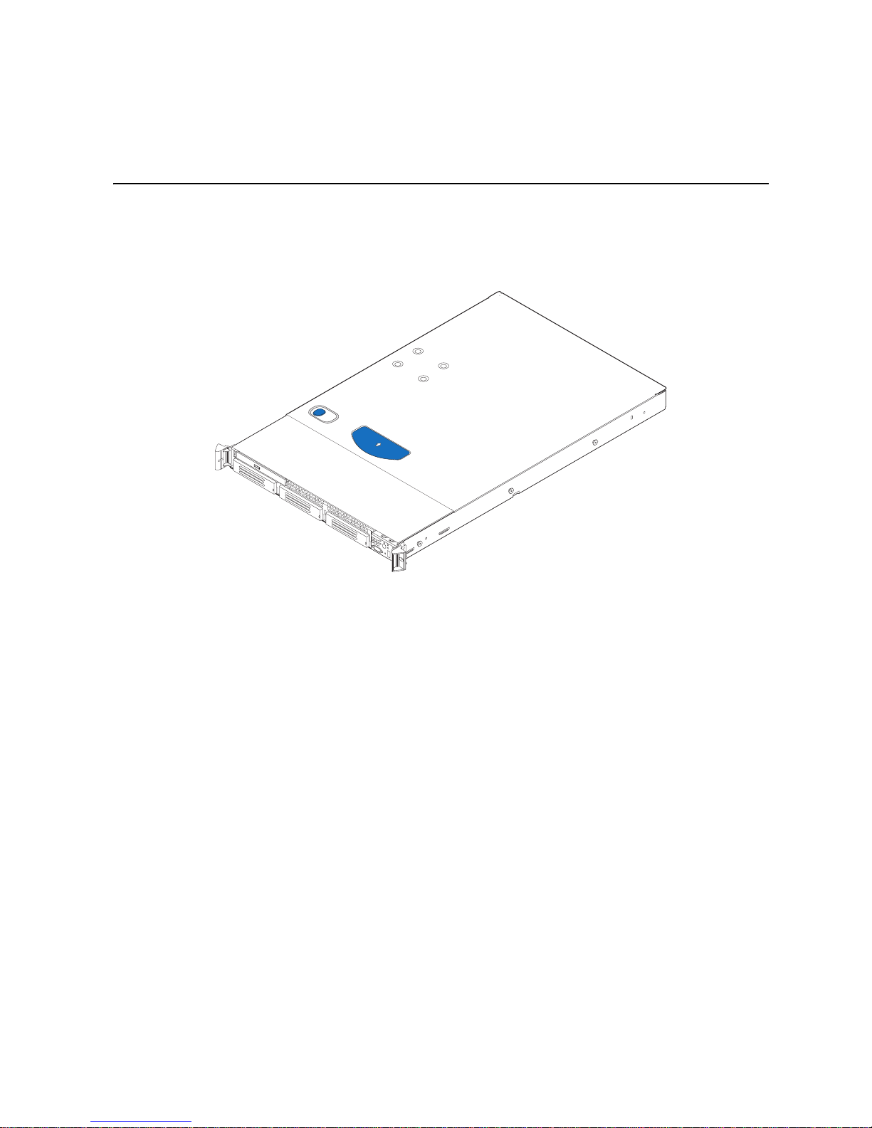
This chapter briefly describes the main features of the server system. This chapter
provides illustrations of the product, a list of the server system features, and diagrams
showing the location of important components and connections on the serv er system.
Figure 1. Intel
®
Server System SR1600UR
Intel® Server System SR1600UR Service Guide 5
Page 24
Server System Feature Overview
Table 2 summarizes the features of the server system.
®
Table 2. Inte l
Feature Description
Server System SR1600UR Feature Summary
Dimensions
• 1.703 inches (43.3 mm) high
• 16.90 inches (430 mm) wide
• 27.19 inches (690.6 mm) deep
• 34 pounds (15.4 kg) - max chassis weight
®
Server Board Intel
Processor Support for one or two Intel
Server Board S5520UR
Socket B pac ka ge wi t h up to 95 W Th ermal Design Power (TDP)
• 4.8 GT/s, 5.86 GT/s and 6.4 GT/s Intel
Interconnect (Intel
®
QPI)
• EVRD11.1
For a complete list of supported processors, see
http://www.intel.com/support/motherboards/server/s5520ur/
compat.htm
Memory
• Twelve DIMMs across six memory channels (three channels
per processor)
• Support for 800/1066/1333 MT/s ECC registered (RDIMM) or
unbuffered (UDIMM) DDR3 memory
• Intel
®
5520 Chipset I/O Hub
®
82801Jx I/O Controller Hub
Chipset • Intel
®
Xeon® Processors in FC-LGA 1366
®
QuickPath
6 Intel® Server System SR1600UR Service Guide
Page 25
Table 2. Inte l® Server System SR1600UR Feature Summary
Feature Description
Peripheral Interfaces External connections:
• DB-15 video connector (back)
• Hot-swap hard drive system only: DB-15 video connector
(front)
• RJ-45 serial Port A connector
• Two RJ-45 10/100/1000 Mb network connections
• Four USB 2.0 connectors (back)
• One USB 2.0 connector (front)
Internal connections:
• One USB 2x5 pin header, which supports two USB 2.0 ports
• One low-profile USB 2x5 pin header to support low-profile USB
Solid State drives
• One DH-10 Serial Port B header
• Six Serial ATA (SATA) II connectors
• Two I/O module connectors
• One RMM3 connector to support an optional Intel
Management Module 3
• SATA Software RAID 5 Activation Key connector
• One SSI-EEB compliant front panel header
• One SSI-EEB compliant 24-pin main power connector
• One SSI-compliant 8-pin CPU power connector
• One SSI-compliant auxiliary power connector
®
Remote
Video On-board ServerEngines* LLC Pilot II Controller
• Integrated 2D Video Controller
• 32 MB DDR2 Memory
LAN Two 10/100/1000 Intel
Expansion Capabilities One x16 PCI Express* Gen 2 PCI riser slot capable of supporting a
full-length full-height PCI Express* add-in card
Hard Drive Options
• Fixed mount hard drive system:
®
82575 PHYs
– Three SATA dr ives
• Hot-swap hard drive system:
– Three 3.5 inch hot-swap SATA/SAS drives
®
• Intel
Embedded Server RAID Technology II with SW RAID
levels 0/1/10
• Optional support for SW RAID 5 with activation key
Peripherals
• Slimline bay for slimline SAT A optical drive
• One PCI Express* X16 Add-in Card slot (Gen 2)
Control Panel
• Standard control panel
• Hot-swap hard drive system only: Intel
®
Local Control Panel
Intel® Server System SR1600UR Service Guide 7
Page 26
Table 2. Inte l® Server System SR1600UR Feature Summary
Feature Description
LEDs and displays LEDs with standard control panel:
• NIC1 Activity
• NIC2 Activity
• Power/Sleep
• System Status
• System Identification
• Hard Drive Activity
Intel® Light-Guided diagnostic LEDs:
• Fan Fault
• DIMM Fault
• CPU Fault
• 5V-STBY
• System Status
• System Identification
• POST Code Diagnostics
Power Supply Single 600-W power supply
Fans • Five 40x40x56-mm, non-redundant, variable-speed, dual-rotor
system fans
• Two non-redundant 40-mm power supply fans
System Management On-board ServerEngines* LLC Pilot II Controller
• Integrated Baseboard Management Controller (Integrated
BMC), IPMI 2.0 compliant
• Integrated Super I/O on LPC interface
®
Support for Intel
System Management Software
8 Intel® Server System SR1600UR Service Guide
Page 27
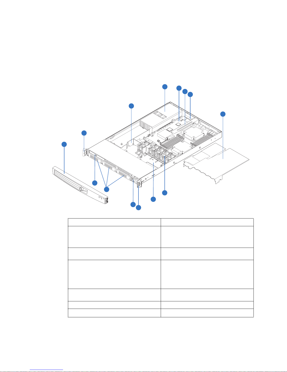
Server System Components
AF002769
M
A
L
K
J
A
I
B
C
G
E
F
D
H
This section helps you identify the components of your server system. If you are near the
system, you can also use the Quick Reference Label provided on the inside of the chassis
cover to assist in identifying components.
A. Rack handles H. System Fan Assembly
B. Air Baffle I. Fan Board used in fixed mount hard drive
C. Power Supply J. Control panel (standard control panel
D. Server Board K. Hard drive bays (drives not included):
Intel® Server System SR1600UR Service Guide 9
E. PCI add-in riser assembly L. Slimline Optical Drive Bay (drive not
F. PCI card bracket (full-height) M. Front bezel (optional
G. Processor air duct
system /
Backpane used in hot-swap hard drive
system
shown)
• Three fixed hard drives supported in fixed
mount hard drive system
• Three hot-swap drives supported in hot-
swap hard drive system
included)
Figure 2. Server System Components
Page 28

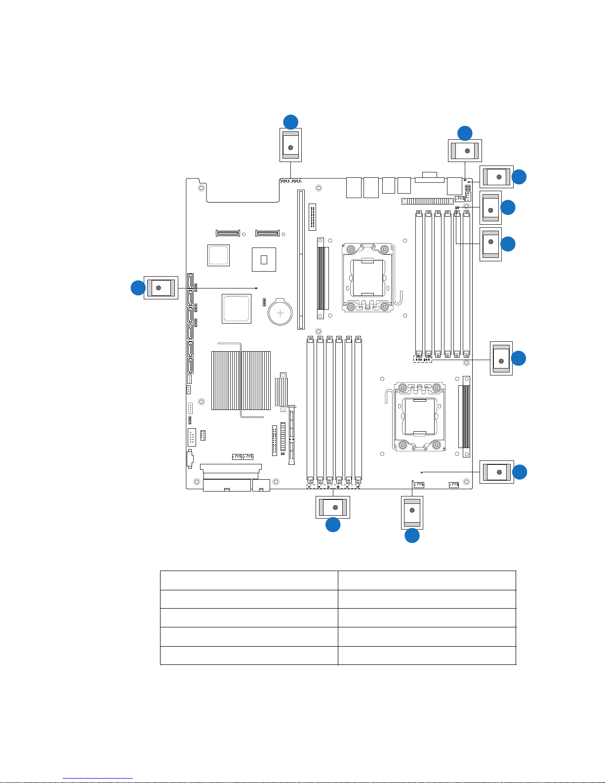
Intel® Light-Guided Diagnostics
The server system contains the following diagnostic LEDs, each providing the following
functions:
• The System Status LED on the front and back panels (see Figure 3 and Figure 6)
shows the overall health of the system (green, blinking green, blinking amber,
amber, off) .
• The System Identification LED on the front and back panel (see Figure 3 and
Figure 6) helps identify the server from among several servers. The ID LED is off
by default, and blue when activated by button or software.
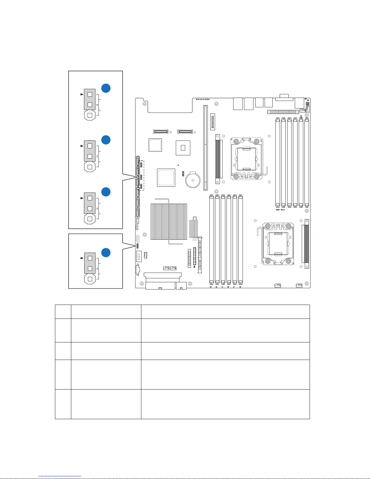
• DIMM Fault LEDs on the server board (see Figure 3) help identify failed and failing
DIMM slots. The DIMM fault LEDs turn on (amber) if there is a DIMM fault.
• POST Code Diagnostic LEDs on the server board (see Figure 3) change color or
state (off, green, red, amber) according to the POST sequence.
• The 5V-STBY LED on the server board (see Figure 3) is illuminated (green) when
AC power is applied.
• Fan Fault LEDs on the fan board (in the fixed mount hard drive system - see
Figure 4) or hot-swap backplane (in the hot-swap hard drive system - see Figure 5)
help identify failed and failing fans. The fan fault LEDs turn on (amber) if there is a
fan fault.
10 Intel® Server System SR1600UR Service Guide
Page 29
A
B
C
D
E
J
F
G
I
J
A. POST Code Diagnostic LEDs B. System Identification LED
C. Status LED D. Memory 1 Fan Fault LED
E. CPU 1 Fan Fault LED F. CPU 1 DIMM Fault LEDs
G. CPU 2 Fan Fault LED H. Memory 2 Fan Fault LED
I. CPU 2 DIMM Fault LEDs J. 5V Standby LED
Figure 3. Intel® Light-Guided Diagnostic LEDs - Server Board
Intel® Server System SR1600UR Service Guide 11
H
AF002833
Page 30
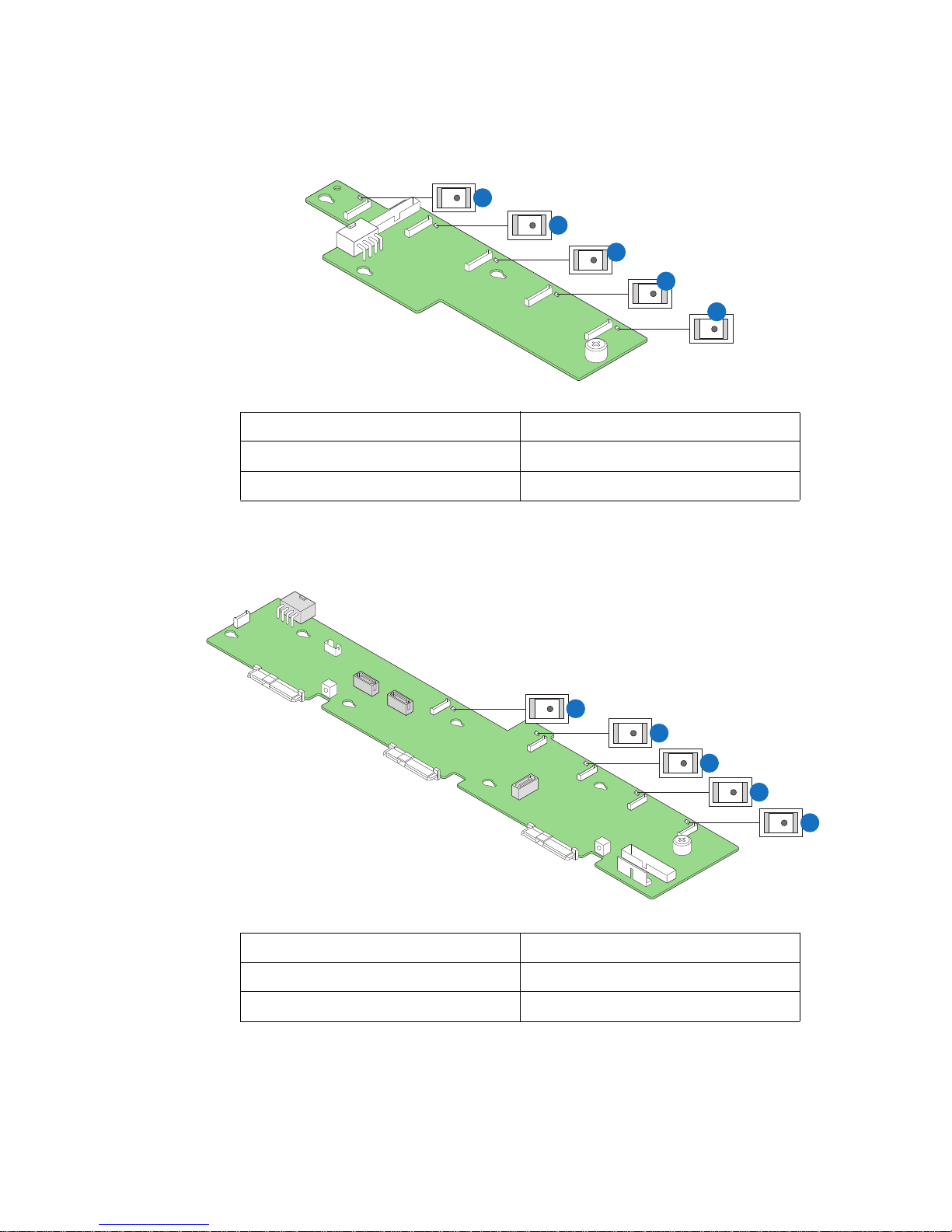
E
D
C
A. Fan 1 Fault LED B. Fan 2 Fault LED
C. Fan 3 Faul t LED D. Fan 4 Faul t LED
E. Fan 5 Fault LED
Figure 4. Intel® Light-Guided Diagnostic LEDs - Fan Board
B
A
AF003000
E
D
C
B
A
AF003001
A. Fan 1 Fault LED B. Fan 2 Fault LED
C. Fan 3 Faul t LED D. Fan 4 Faul t LED
E. Fan 5 Fault LED
Figure 5. Intel
12 Intel® Server System SR1600UR Service Guide
®
Light-Guided Diagnostic LEDs - Hot-swap Backplane (Passive Shown)
Page 31
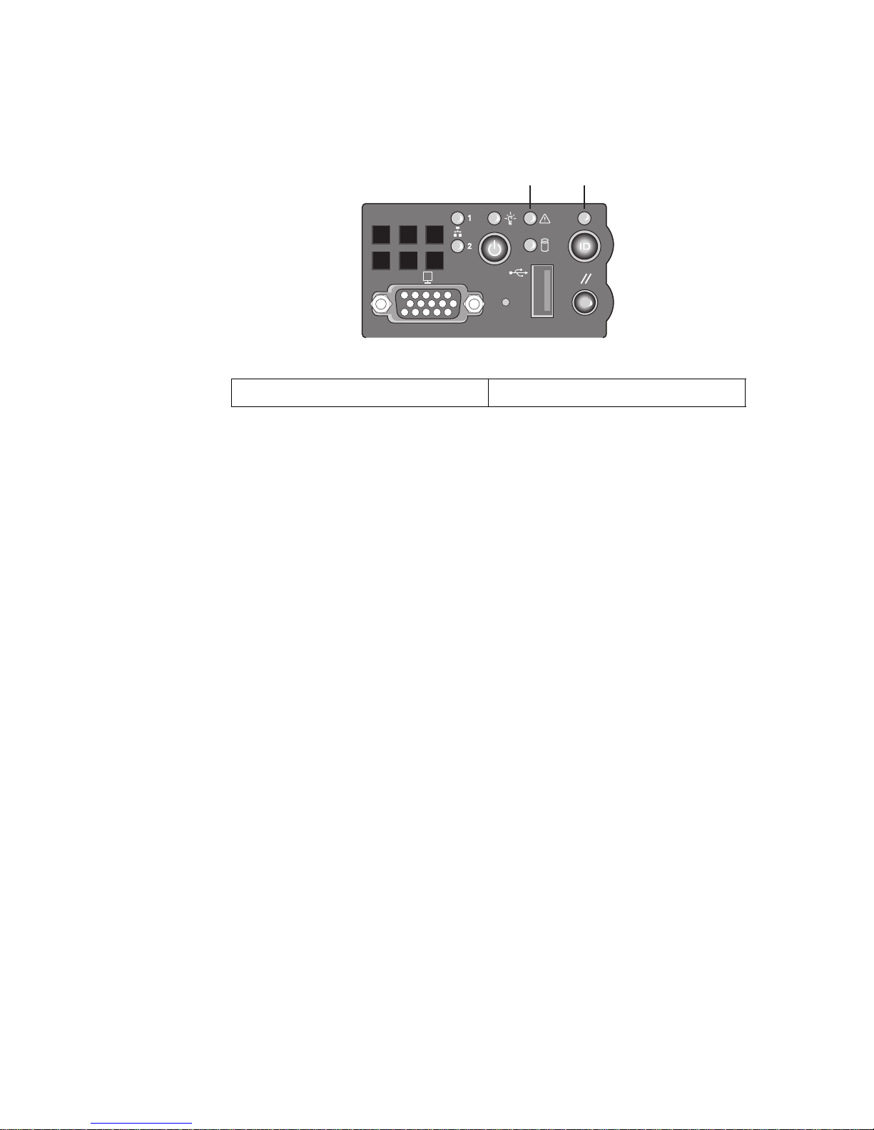
A B
AF003002
A. Status LED B. System Identification LED
Figure 6. Intel® Light-Guided Diagnostic LEDs - Standard Control Panel
Intel® Server System SR1600UR Service Guide 13
Page 32

Server Board Components
DD
EB C F GDA
H
I
CC
BB
AA
W
J
K
Z
Y
X
L
V
U
T
MNS R OPQ
AF002696
14 Intel® Server System SR1600UR Service Guide
Page 33

A. 280-pin In tel® Adaptive Slot B. POST Code Diagn ostic LEDs C. Intel® RMM3 Header
D. Processor 1 Socket E. Back Panel I/O Ports F. System Identification LED
G. System Status LED H. Memory 1 Fan Header I. Processor 1 Fan Header
J. Processor 1 DIMM slots K. Processor 2 DIMM slots L. Processor 2 Socket
M. Processor 2 Fan Header N. Memory 2 Fan Header O. Bridge Board Connector (Intel
Server Chassis)
P. Front Panel Connector Q. Fan Board Connector R. 2x4 Power Connector
®
S. Main Power Connector T. Power Supply SMBus
U. System 2 Fan Header
Connector
V. USB Header W. Low-profile USB Solid State
X. System 1 Fan Header
Drive Header
Y. LCP IPMB Header Z. SATA RAID 5 Key Header AA. SGPIO Header
BB. SATA Connectors CC. I/O Module Mezza nine
Connector 2
DD. I/O Module Mezzanine
Connector 1
Figure 7. Server Board Connector and Component Locations
Intel® Server System SR1600UR Service Guide 15
Page 34
Configuration Jumpers
BIOS Recover
J1D4
D
2
3
Password Clear
2
3
BIOS Default
2
3
BMC Force Update
2
3
Normal
Recover
J1E8
Protect
Clear
J1E7
Normal
Set
Default
J1H2
Disable
Enable
C
B
A
AF002832
Jumper Name Jumper Purpose
A. BMC Force Update
(J1H2)
If pins 2-3 are jumpered, the In tegra ted BMC F orce Update Mode is
enabled. These pins should be jumpered on 1-2 for normal system
operation.
B. BIOS Default (J1E7) If pins 2-3 are jumpered, the BIOS settings are cleared on the next
reset. These pins should be jumpered on 1-2 for normal operation.
C. Password Clear (J1E8) If pins 2-3 are jumpered, administrator and user passwords are
cleared within five to ten seconds after the system is powered on.
These pins should be jumpered on 1-2 for normal system
operation.
D. BIOS Recover (J1D4) If pins 2-3 are jumpered, the system can only boot from EFI-
bootable recovery media with the recovery BIOS image. The main
system BIOS will not boot. These pins should be jumpered on 1-2
for normal system operation.
Figure 8. Configuration Jumpers
16 Intel® Server System SR1600UR Service Guide
Page 35

Front of Server System
Peripheral Devices
The server system provides locations and hardware for installing hard drives, a USB
floppy drive (hot-swap hard drive systems only), and an optical drive. The drives must be
purchased separately. The following figure shows the available options.
A B
D C
TP02156
.
A. Slimline drive bay (drive not included)
B. Control panel (Standard control panel
shown)
C. Hard Drive Status LEDs (hot-swap drives
only)
D . Hard drive bays (drives not included)
Figure 9. Optional Peripherals
Intel® Server System SR1600UR Service Guide 17
Page 36

Hard Disk Drive Carriers
The fixed mount hard drive server system (Product Code: SR1600UR) ships with three
fixed mount drive carriers for installing three SATA hard drives.
The hot-swap hard drive server system (Product Code: SR1600URHS) ships with three
hot-swap drive carriers for installing three SAS or Serial ATA (SATA) drives. The
leftmost hard drive bay can be used to support a USB floppy drive this system. To use the
bay for a floppy drive, the AXXUSBFLOPPY accessory kit must be used.
Note: The USB floppy drive kit is supported on the Intel
Code: SR1600URHS) only .
For instructions on installing hard drives, see the following sections:
• “Installing and Removing a Fixed Mount Hard Drive (Fixed Mount Hard Drive
System Only)” on page 57
• “Installing and Removing a Hot-swap Hard Drive (Hot-swap Hard Drive System
Only)” on page 61
Note: Drives can consume up to 17 watts of power each. Drives must be specified to run at a
maximum ambient temperature of 45C.
®
Note: The Intel
drives. For a list of supported hard drives, use the Server Configurator Tool. For a web
link to this tool, see “Additional Information and Software” on page 3.
Server System SR1600UR does not support all SAS or Serial ATA (SATA) hard
®
Server System SR1600UR (Product
Slimline Optical Drive Carrier
The system includes a slimline optical drive carrier, which can be used to install an
optional SATA optical drive. The optical drive must be purchased separately. You cannot
install both an optical drive and a USB floppy drive.
The slimline optical drive carrier can be inserted or removed only when system power is
turned off. Drive in the optical drive carrier is NOT hot swappable. For installation
instructions on installing an optical drive or USB floppy, see “Installing and Removing a
Slimline Optical Drive or Internal USB Floppy” on page 63.
To use one of the drives provided by Intel, use the following order codes:
• Slimline DVD-ROM Drive: AXXSATADVDROM
• Slimline DVD-RW Drive: AXXSATADVDRWROM
Note: The Intel
list of supported slimline optical drives, use the Server Configurator Tool. For a web link
to this tool, see “Additional Information and Software” on page 3. Intel provides
accessory kits for these drives.
®
Server System SR1600UR does not support all slimline optical drives. For a
18 Intel® Server System SR1600UR Service Guide
Page 37

Control Panel
TP02160
L JK
H
I
BA F GEDC
The Intel® Server System SR1600UR supports the following types of control panels:
• Standard Control Panel
• Intel
Standard Control Panel
The following diagram identifies the features available on the standard control panel. For
instructions on installing the standard control panel, see “Replacing the Control Panel
Module (Hot-swap Hard Drive System only)” on page 88.
®
Local Control Panel (hot-swap hard drive systems only)
Callout Feature Function
A.
B.
C. Power/Sleep Button Powers on/off the system.
D. Power/Sleep LED Continuous green light indicates the system has power applied to
E. Hard Disk Drive
NIC 2 Activity LED
NIC 1 Activity LED
Activity LED
Continuous green light indicates a link between the system and
the network to which it is connected.
Blinking green light indicates network activity.
If enabled by an ACPI-compliant operating system, this button
functions as a Sleep button and puts the system in an ACPI sleep
state.
it or the system is in ACPI S0 state.
Blinking green indicates the system is in sleep or ACPI S1 state.
No light indicates the power is off or the system is in ACPI S4 or
S5 state.
Random blinking green light indicates hard disk drive activity
(SAS or SATA).
No light indicates no hard disk drive activity.
Intel® Server System SR1600UR Service Guide 19
Page 38

Callout Feature Function
F. System Status LED Solid green indicates normal operation.
Blinking green indicates degraded performance.
Solid amber indicates a critical or non-recoverable condition.
Blinking amber indicates a non-critical condition.
No light indicates POST is running or the system is off.
G. System Identification
LED
H. System Identification
Button
I. Reset Button Reboots and initializes the system.
J. USB Port Allows you to attach a USB component to the front of the system.
K. NMI Button Puts the server in a halt-state for diagnostic purposes and allows
L. Video Port Allows you to attach a video monitor to the front of the system.
Solid blue indicates system identification is active.
No light indicates system identification is not activated.
Turns on/off the system identification LED.
you to issue a non-maskable inte rrupt. After issuing the interrupt,
a memory download can be performed to determine the cause of
the problem.
The front and rear video ports cannot be used at the same time.
NOTE: The video port option is only available on the hot-swap
hard drive system (Product Code: SR1600URHS).
Intel® Local Control Panel
The following diagram identifies the features available on the Intel® Local Control Panel.
®
Note: The Intel
(Product Code: SR1600URHS).
For instructions on installing the standard control panel, see “Replacing the Control Panel
Module (Hot-swap Hard Drive System only)” on page 88.
Local Control Panel is only supported in the hot-swap hard drive system
Figure 10. Standard Control Panel
BA
C
D
E
F
O M L K J HIN G
TP02099
20 Intel® Server System SR1600UR Service Guide
Page 39

Callout Feature Function
A. USB Port Allows you to attach a USB component to the front of the system.
B. LCD Display Screen on which system information is displayed.
C. Menu Control Button,
Scroll Up
D. Menu Control Button,
E. Menu Control Button,
F. Menu Control Button,
G. System Identification
H. Power/Sleep LED Continuous green light indicates the system has power applied to
I. Power/Sleep Button Powers on/off the system.
J. System Status LED Solid green indicates normal operation.
K.
L.
M. Hard Disk Activity
N. Reset Button Reboots and initializes the system.
O. USB Port Allows you to attach a USB component to the front of the system.
Scroll Down
Scroll Left
Enter
LED
NIC 2 Activity LED
NIC 1 Activity LED
LED
Scroll up one option at a time.
Scroll down one option at a time.
Move to the previous option.
Select option.
Solid blue indicates system identification is active.
No light indicates system identification is not activated.
it or the system is is S0 state.
Blinking green indicates the system is in sleep or ACPI S1 state.
No light indicates the power is off or the system is in ACPI S4 or
S5 state.
If enabled by an ACPI-compliant operating system, this button
functions as a Sleep button and puts the system in an ACPI sleep
state.
Blinking green indicates degraded performance.
Solid amber indicates a critical or non-recoverable condition.
Blinking amber indicates a non-critical condition.
No light indicates POST is running or the system is off.
Continuous green light indicates a link between the system and
the network to which it is connected.
Blinking green light indicates network activity.
Random blinking green light indicates hard disk drive activity
(SAS or SATA).
No light indicates no hard disk drive activity.
Intel® Server System SR1600UR Service Guide 21
Figure 11. Intel® Local Control Panel
Page 40

Bezels
The optional front bezels provide a snap-on design that allows for maximum airflow
through the server system. Two bezels are available. One fits a system that has the
standard control panel installed (with or without a video port). The other is used only in a
hot-swap hard drive system with the Intel
Each bezel provides a lock to secure the hard drive and optical drive area. For instructions
on installing either of the front bezels, see “Installing the Front Bezel” on page 37.
The order numbers for the bezels are:
• ADWBEZBLACK: Black bezel for use with the standard control panel.
• ADWLCDBEZEL: Black bezel for use with the Intel
Rear of Server System
®
Local Control Panel installed.
®
Local Control Panel.
A
F
I
A. Add-in card bracket (full-height) F. NIC 2 connector
B. AC Power Receptacle G. Four USB 2.0 connectors
C. IO module external connector (optional) H. Video connector
D. Management Network Interface (optional) I. RJ-45 serial B port connector
E. NIC 1 connector
22 Intel® Server System SR1600UR Service Guide
G
H
E
D
Figure 12. Server System Back Panel
C
B
AF002731
Page 41

Back Panel Connectors
A. Serial Port A (RJ-45) B. Video
C. USB Ports 0 and 1 D. USB Ports 2 and 3
E. NIC 1 (10/100/1000 Mb) F. NIC 2 (10/100/1000 Mb)
Figure 13. Back Panel Connectors
The NIC LEDs at the right and left of each NIC provide the following information.
Table 3. NIC LED Descriptions
LED LED State Description
Right Off No network connection
Solid Green Network connection in place
Blinking Green Transmit/receive activity
Left Off 10 Mbps connection (if right LED is on or blinking)
Solid Green 100 Mbps connection
Solid Amber 1000 Mbps connection
Intel® Server System SR1600UR Service Guide 23
Page 42

SAS/SATA Backplanes
TP02172
B
A
E
F
J
I
K
H
L
G
M
C
D
The hot-swap hard drive system (Product Code: SR1600URHS) can support either an
active SAS (Product Order Code: ASR1500SASBP) or a passive SAS/SATA backplane
(Product Order Code: ASR1500PASBP). The backplanes provide the platform support for
peripheral drives and hot-swap SAS or SAT A hard drives. To eliminate several cables, the
backplanes are also used as a pathway for signals from the server board to various
platform interconnects, including those for the control panel and peripheral drives.
Active Backplane
The active backplane has a built-in SAS controller that does not need communication with
the baseboard controller or an add-in card. The following diagram shows the location for
each connector found on the active backplane.
A. Backplane Power H. Fan 2 Power
B. USB Floppy Connector I. Front Panel Connector
C. SW RAID Activation Key J. Fan 1 Power
D. Fan 5 Power K. Screw
E. Bridge Board Connector L. Front Panel USB
F. Fan 4 Power M. Hot-swap SAS/SATA Connectors
G. Fan 3 Power
24 Intel® Server System SR1600UR Service Guide
Figure 14. Active SAS Backplane Components
Page 43
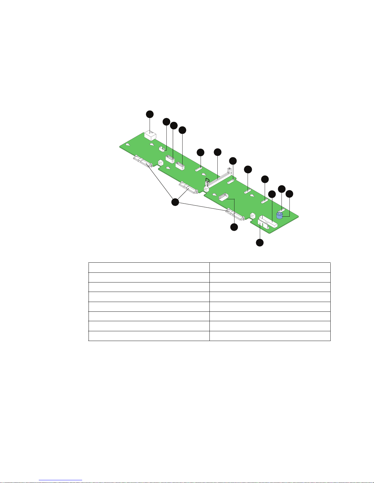
Passive Backplane
The passive backplane acts as a 'pass-through' for the SAS/SATA data from the drives to
the SATA controller on the server board or a SAS/SAT A controller add-in card. It provides
the physical requirements for the hot-swap capabilities. The following diagram shows the
location for each connector found on the passive backplane.
A
B
C
D
F
E
G
I
H
I
K
L
J
O
N
M
AF002999
A. Backplane Power I. Fan 2 Power
B. USB Floppy Connector J. Front Panel Connector
C. SATA 0 K. Fan 1 Power
D. SATA 1 L. Screw
E. Fan 5 Power M. Front Panel USB
F. Bridge Board Connector N. SATA 2
G. Fan 4 Power O. Hot-swap SAS/SATA Connectors
H. Fan 3 Power
Figure 15. Passive SAS/SATA Backplane Components
Intel® Server System SR1600UR Service Guide 25
Page 44

RAID Support
The server system provides an embedded SATA controller on the server board that is
accessible through the passive backplane. The SATA controller supports both 1.5 and 3.0
Gbps data transfer rates.
The BIOS Setup utility provides multiple drive configuration options on the Advanced |
ATA Controller setup page, some of which affect the ability to configure RAID. The
Onboard SATA Controller option is enabled by default. When this option is enabled, the
SATA Mode option can be set to either Legacy or Enhanced. The Legacy and Enhanced
modes affect the RAID configuration as follows:
• Legacy supports four disk drives and does not provide RAID support.
• Enhanced supports six disk drives and is required for RAID configurations.
When the enhanced mode is selected, you can choose to enable or disable “AHCI Mode”
or “Configure SATA as RAID”. The Intel
enabled by the “Configure SATA as RAID” option. The Intel
Technology II feature provides RAID modes 0, 1, and 10.
For RAID 0, 1, and 10, enclosure management is provided over the bridge board.
If RAID 5 is desired, the optional Intel
installed. T o enable RAID 5, this activation key is pl aced on the SATA Key connector th at
is located at the left side of the server board.
For information on configuring RAID, see the Intel
included on the Intel
®
Server Deployment Toolkit 3.0 CD.
®
Embedded Server RAID Technology II is
®
RAID Activation Key AXXRAKSW5 can be
Advanced Management Options
Intel® Remote Management Module 3
The Intel® Remote Management Module 3 plugs into a dedicated connector on the server
board and provides additional server management functionality to the server board.
This module provides a dedicated web server for viewing server information and remote
control of the system. It also provides Remote KVM Redirection and USB Media
Redirection allowing USB devices attached to the remote system to be used on the
managed server.
®
Embedded Server RAID
®
RAID Software User’s Guide that is
For instructions on installing the Intel
and Removing the Intel
26 Intel® Server System SR1600UR Service Guide
®
®
Remote Management Module 3” on page 70.
Remote Management Module 3, see “Installing
Page 45

Rack Mount Options
Your Intel® Server System SR1600UR can be mounted into a rack. Intel provides the
following three options to mount this server system into a rack:
• Fixed mount relay rack/cabinet mount kit: This kit can be configured to mount the
system into either a 2-post rack or 4-post cabinet.
• Tool-less sliding rail kit: This kit is used to mount the system into a standard (19
inches by upto 30 inches deep) EIA-310D compatible server cabinet. An optional
cable management arm can be used with this kit.
• Basic three-quarter extension sliding rail kit: This kit is used to mount the system
into a standard (19 inches by upto 30 inches deep) EIA-310D compatible
server cabinet.
When installing the system into a rack, Intel recommends you install systems from the
bottom of the rack to the top. In other words, install the first system in the rack into the
bottom position of the rack, the second system in the second position from the bottom, and
so on. For instructions on installing your system into a rack, see “Removing and Installing
from a Rack” on page 33. These instructions are also included in each rackmount
option kit.
Intel® Server System SR1600UR Service Guide 27
Page 46

28 Intel® Server System SR1600UR Service Guide
Page 47

3 Hardware Installations and Upgrades
Before You Begin
Before working with your server product, pay close attention to the “Safety Information”
on page v at the beginning of this manual.
Note: Whenever you service the system, you must first power down the server and unplug all
peripheral devices and the AC power cord.
Tools and Supplies Needed
• Phillips* (cross head) screwdrivers (#1 bit and #2 bit)
• Needle nosed pliers
• Antistatic wrist strap and conductive foam pad (recommended)
System References
All references to left, right, front, top, and bottom assume the reader is facing the front of
the server system as it would be positioned for normal operation.
Intel® Server System SR1600UR Service Guide 29
Page 48
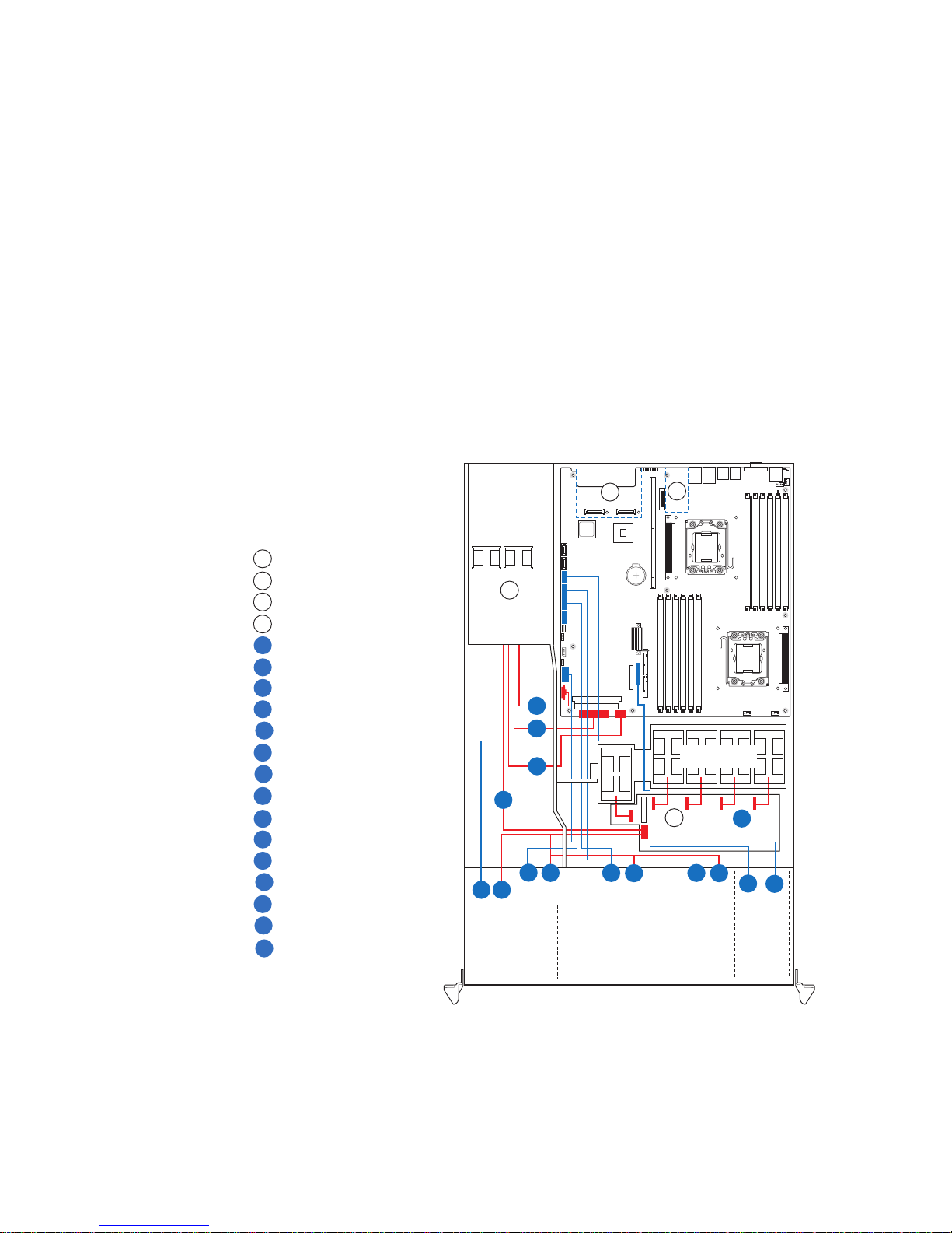
Cable Routing
AF002876
A
B
I/O Module
C
Power Supply
D
Fan Board
Power to Server Board (Aux. - P4)
Power to Server Board (Main - P1)
Power to Server Board (CPU - P2)
Power to Fan Board (P3)
Fan Power Cables
Control Panel USB
Control Panel Data
Power to Fixed HDD 0
SATA Data to Fixed HDD 0
Power to Fixed HDD 1
SATA Data to Fixed HDD 1
SATA Data to Optical Drive
Intel® Remote Management Module 3
F
G
H
I
J
K
L
M
N
O
P
Q
R
L
E
Power to Fixed HDD 2
SATA Data to Fixed HDD 2
Drive Bays
Optical
Drive
Module
Control
Panel
Module
CPU2
CPU1
Server
Board
Power
Supply
Fan Module
A
B
F
E
G
H
L
M N P
Q
J
K
I
O
Fan Board
HDD0 HDD1 HDD2
R S
C
D
Power to Optical Drive
S
When you add or remove components from your server system, make sure your cables are
routed correctly before reinstalling the server system cover. Use caution to make sure no
cables or wires are pinched and that the airflow from the fans is not blocked. Use the
figures below to determine the correct cable routing.
Fixed Mount Hard Drive System
Use the following figure to determine the correct cable routing for a fixed mount hard
drive system.
30 Intel® Server System SR1600UR Service Guide
Figure 16. Cable Routing (Fixed Mount Hard Drive System)
Page 49

Cabling Around the Small Air Baffle
In a fixed mount hard drive system, route the following cables through the air baffle
notches (as shown in Figure 17):
• Main Power Cable
• CPU Power Cable
• Power Signal Cable
• Optical Drive Data Cable
• SATA 0-2 HDD Data Cables
• SATA 0-2 HDD Power Cables
Optical Drive
Front
Ta b
Backplane
SATA 0 HDD
SATA 1 HDD
SATA 2 HDD
Power
Supply
Air Baffle
A
Power
Supply
Main Power
CPU Power
Power Signal
SATA Connector
SATA Connectors
Fixed
SATA
Drive 0
SATA
Drive 1
Fixed
Standoff Detail
Drive Bay Cover
Fixed
SATA
Drive 2
AF002878
Figure 17. Cabling Around the Small Air Baffle (Fixed Mount Hard Drive System)
Intel® Server System SR1600UR Service Guide 31
Page 50

Hot-swap Hard Drive System
Use the following figure to determine the correct cable routing for a hot-swap hard
drive system.
Intel® Remote Management Module 3 (optional)
A
I/O Module (optional)
B
Power Supply
C
Bridge Board
D
Backplane Board (Passive shown)
E
Power to Server Board (Aux. - P4)
F
Power to Server Board (Main - P1)
G
Power to Server Board (CPU - P2)
H
Power to Backplane Board (P3)
I
Control Panel USB
J
Control Panel Data
K
Fan Power Cables
L
SATA Data to HDD 0, 1, 2
M
Power to Optical Drive
N
SATA Data to Optical Drive
O
Power
Supply
I
N O
Optical
Drive
Module
B
Server
Board
C
A
CPU1
M
M
M
F
G
D
Fan Module
CPU2
H
E
Drive Bays
L
J
K
Control
Panel
Module
Figure 18. Cable Routing (Hot-swap Hard Drive System)
Cabling Around the Small Air Baffle
In a hot-swap hard drive system, route the following cables through the air baffle notches
(as shown in Figure 19):
• Main Power Cable
• CPU Power Cable
• Power Signal Cable
32 Intel® Server System SR1600UR Service Guide
AF002875
Page 51
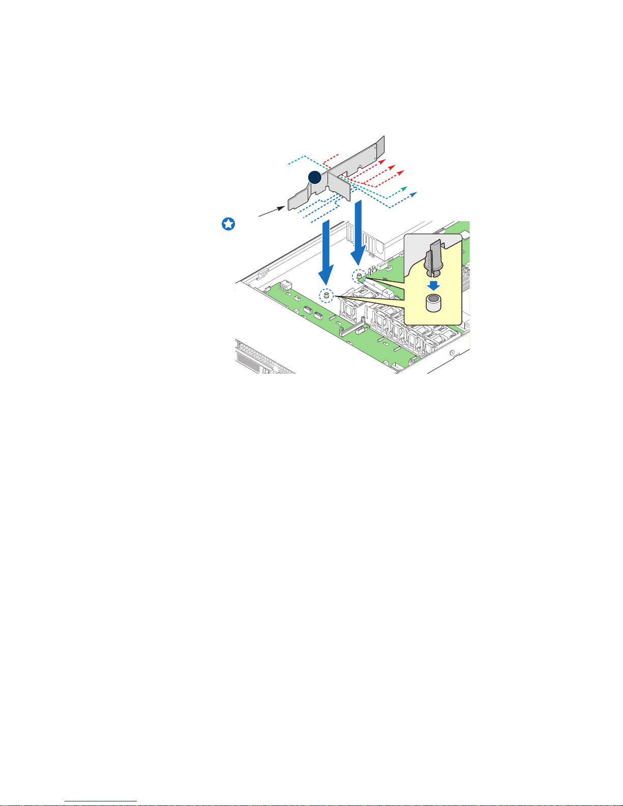
• Optical Drive Data Cable
• SATA 0-2 HDD Data Cables (passive backplane only)
Power
Optical Drive
Supply
Air Baffle
A
Power Signal
Main Power
CPU Power
SATA Connector
SATA Connectors
Front
Ta b
SATA 0 HDD
SATA 1 HDD
SATA 2 HDD
Snap
Stand-offs
Figure 19. Cabling Around the Small Air Baffle (Hot-swap Hard Drive System)
Removing and Installing from a Rack
To install the Intel® Server System SR1600UR in a rack, three Intel® rack options
are available:
Standoff Detail
AF003019
• Fixed mount relay rack/cabinet mount kit
This rack option requires the system to removed from the rack before servicing.
• Basic sliding rail kit
This rack option requires the system to removed from the rack before servicing.
• Tool-less sliding rail kit
Only the tool-less rail kit allows you to service the server system while installed in
a rack.
Note: Follow all safety guidelines while removing a system from a rack to avoid injury.
Intel® Server System SR1600UR Service Guide 33
Page 52

Fixed Bracket Rack Mount Removal
1. Disconnect all cables from the back of the system.
Note: Remember to use the system LED to properly identify the system you are servicing.
2. Remove screws from the brackets and remove the system from the rack.
Fixed Bracket Rack Mount Installation
1. Fully extend a rail assembly; the finger tab for the extension lock is revealed.
2. Press the finger tab and slide the inside rail from the middle rail until it
ompletely separates.
Note: The middle rail and outer rail cannot be separated.
3. Position an inside rail along one side of the chassis with the finger tab facing
outward and located closer to the rear of the chassis.
4. Align the holes in the rail with the tabs on the chassis and place the rail against
the chassis.
5. Slide the rail as far as it will go toward the front of the chassis to engage the tabs.
6. Fasten the rail to the chassis using one screw at the front of the chassis.
7. In the same manner, attach the other inside rail to the other side of the chassis
8. Using two screws, attach one nut bar to the inside of the rack post. Do not
completely tighten the screws; leave them loose enough to allow insertion of the
brackets in the next step.
9. Insert the slotted foot of a rail bracket between each nut bar and post.
10. Align the face of the bracket foot with the inside edge of the rack post and firmly
tighten the screws.
11. Repeat steps 8 to 10 above to install the other 3 brackets (2 front & 2 back). Ensure
all brackets are at the same height on the rack.
12. Position a rail assembly (middle and outer rails) with its black plastic end caps
toward the rear of the rack and its outer rail closest to the brackets.
13. Align the front screw hole in the outer rail with the threaded hole nearest the front
of the front bracket and fit the rail assembly into the front and rear brackets.
14. Slide the middle rail toward the front until the access hole in the middle rail is
aligned with the front screw hole in the outer rail.
15. Insert screw through the access hole and loosely attach the outer rail to the
front bracket.
16. In a similar manner to steps 13 through 15, install a screw through a slot in the outer
rail and into the rear-most threaded hole in the front bracket. Firmly tighten
this screw.
17. Firmly tighten the front screw installed loosely in step 15.
34 Intel® Server System SR1600UR Service Guide
Page 53

18. In the same manner, attach the other rail assembly to the other side.
19. Slide the middle rail toward the front until the rear bracket area is accessible.
20. Attach the rear end of the outer rail to the rear bracket with at least one screw. If
possible, attach at two places.
21. In the same manner, attach the other rail assembly to the other side.
22. Fully extend the left and right rails until the extension locks have engaged and the
rails will not push back in. The rail system is now ready to receive the chassis.
Caution: Lifting and placing the chassis in the rails is a two-person job. If needed, use an
appropriate lifting device.
23. With the chassis front facing you, lift the chassis and carefully insert the rails
attached to the chassis in the extended rails.
24. Slide the chassis toward the rear of the cabinet until the rails lock together.
25. Depress and hold down the finger tabs on both extension locks while sliding the
chassis toward the rear.
26. Slide the chassis all the way into the rack until the chassis handles are against the
front posts.
Basic Rail Rack Mount Removal
1. Disconnect all cables from the back of the system.
Note: Remember to use the system LED to properly identify the system you are servicing.
2. Pull system from rack until brackets are fully extended.
3. Push in both clips on the brackets and slide the system forward until the inner rail
separates from the outer rail.
4. Remove and service the system.
Basic Rail Rack Mount Installation
1. Extend the inner rail until it locks.
2. Depress the spring safety lock to release the inner rail.
3. Remove the inner rail from the rail assembly.
4. Attach the outer rail slides to the rack posts using two #10-32 x 1/2 screws at the
front posts, and two #10-32 x 1/2 screws at the rear posts.
Note: The rail flanges mount to the inside of each post.
5. Insert the inner rails over the server chassis sidewall studs.
6. Slide the inner rails toward the front of the server chassis.
7. Secure the inner rails with one #6-32 x 1/4 screw for each rail.
Intel® Server System SR1600UR Service Guide 35
Page 54

8. Align the inner rails (attached to the server chassis) with the outer rail assemblies
(attached to the rack).
9. Engage the matching rails and slide the server chassis into the rack until the two
safety stops lock into position.
10. Depress the two safety locks (one on each side).
11. Slide the server chassis all the way into the rack.
12. Use the rack screws (#10-32 x 3/4) to secure the chassis and rack handles into the
rack.
Tool-less Rail Rack Mount Servicing
1. To service the system, pull the system out from the rack.
2. Disconnect the power cable(s) and proceed with servicing the system.
3. When the servicing is completed, re-connect the power cable(s).
4. Pull up on the green tabs on each rail and slide the system back into the rack.
Note: Beware of cables when re-installing the system into the rack so that the cables do not get
pulled or interfered with.
Installing and Removing the Front Bezel
The front bezels are available as optional accessories for the Intel® Server System
SR1600UR. The following front bezel options are available:
• Bezel for use with the Standard Control Panel (Product Order Code:
ADWBEZBLACK)
• Bezel for use with the Intel
ADWLCDBEZEL)
T o identify your bezel, see the following figures. Note the orientation in the figures below
- the control panel is at the right. If you are installing a bezel on your server system, make
sure you position it as shown.
Figure 20. Front View with Bezel supporting the Standard Control Panel
®
Local Control Panel (Product Order Code:
TP02197
36 Intel® Server System SR1600UR Service Guide
Page 55

Figure 21. Front View with Bezel supporting the Intel® Local Control Panel
Installing the Front Bezel
Before installing the bezel, you must install the rack handles. For instructions, see
“Installing the Rack Handles” on page 94.
To install the front bezel, follow these steps:
1. At each end of the bezel, line up the center notch on the bezel with the center guide
on the rack handles.
2. Push the bezel onto the front of the server system until it clicks into place.
TP02198
Intel® Server System SR1600UR Service Guide 37
AF002770
Figure 22. Installing the Front Bezel
Page 56

Removing the Front Bezel
To remove the front bezel, follow these steps:
1. Unlock the bezel.
2. Pull the bezel from the server system.
Figure 23. Removing the Front Bezel
Removing and Installing the System Cover
Removing the System Cover
The server system must be operated with the system cover in place to ensure proper
cooling. You will need to remove the top cover to add or replace components inside of the
server. Before removing the system cover, power down the server and unplug all
peripheral devices and the AC power cable(s).
Note: A nonskid surface or a stop behind the server system may be needed to prevent the server
system from sliding on your work surface.
To remove the server system cover, follow these steps:
1. Remove the safety screw if it is installed (see letter "A" in Figure 24).
2. While holding in the blue button at the top of the server system in (see letter "B" in
Figure 24), slide the top cover back until it stops (see letter "C" in Figure 24).
AF002880
3. Insert your finger in the notch (see letter “D” in Figure 24) and lift the cover
upward to remove it.
38 Intel® Server System SR1600UR Service Guide
Page 57

D
C
Figure 24. Removing the Server System Cover
Installing the System Cover
To install the server system cover, follow these steps:
1. Place the cover over the server system so that the side edges of the cover sit just
inside the server system sidewalls.
2. Slide the cover forward until it clicks into place (see letter “A” in Figure 25).
3. (Optional) Insert the safety screw at the center of the top cover (see letter “B” in
Figure 25) if required.
B
A
AF002939
Intel® Server System SR1600UR Service Guide 39
Page 58
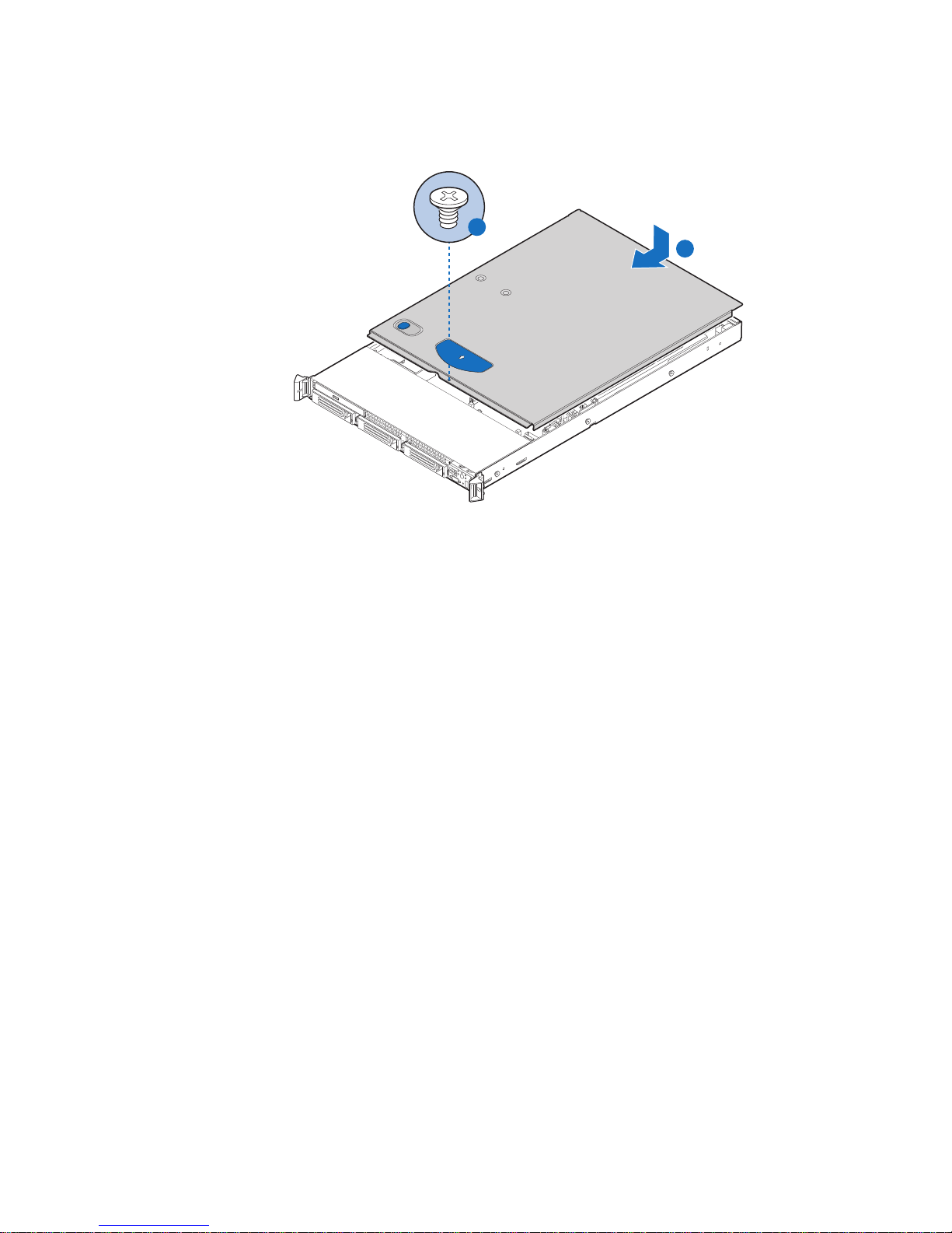
Figure 25. Installing the Server System Cover
TP02196
A
B
40 Intel® Server System SR1600UR Service Guide
Page 59
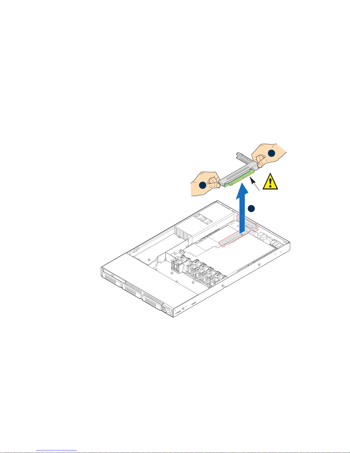
Removing and Installing the PCI Riser Assembly
Riser Card
Connector
AF002894
A
B
A
Removing the PCI Riser Assembly
To remove the PCI riser assembly, follow these steps:
1. Disconnect any cables attached to any add-in cards.
2. Grasp both riser latches with thumb and forefinger (see letter “A” in Figure 26),
and pull up to release riser assembly.
3. Lift riser assembly straight up (see letter “B” in Figure 26).
Figure 26. Removing PCI Riser Assembly from the Server System
Caution: Place the riser assembly upside down to avoid damage to the riser card connector.
4. Do one of the following:
— If you need to add or replace a PCI add-in card, see “Installing and Removing a
PCI Add-in Card” on page 44.
— If you need to add or replace a PCI riser connector, see “Replacing a PCI Riser
Card” on page 43.
Intel® Server System SR1600UR Service Guide 41
Page 60

— If you removed the PCI riser assembly for another procedure, continue with that
procedure.
Installing the PCI Riser Assembly
To install the PCI riser assembly, follow these steps:
1. Lower the riser assembly into place (see letter “A” in Figure 27).
2. Align the two hooks in the riser assembly with the matching slots at the back of the
server system (see letter “B” in Figure 27).
Hooks (2)
B
Riser Card
Edge Connector
Chassis
A
B
Slots (2)
Processor
Air Duct
PCI Riser
Socket
Air Duct
Slot
AF002895
Figure 27. Installing PCI Riser Assembly into the Server System
3. Press down uniformly until the two hooks on the rear of the PCI riser assembly
engage the server system back panel slots. The riser card seats into the matching
sockets on the server board.
4. Connect any cables to add-in cards that require them. See your add-in card
documentation for information and add-in card requirements.
42 Intel® Server System SR1600UR Service Guide
Page 61

Replacing a PCI Riser Card
AF003040
Caution: PCI riser connectors are NOT hot-swappable. Before removing or replacing the riser
connector, you must first take the server out of service, turn off all peripheral devices
connected to the system, turn off the system by pressing the power button, and unplug the
AC power cord from the system or wall outlet.
Removing the PCI Express* Riser Card
To remove the PCI Express* riser card, follow these steps:
1. Disconnect any cables attached to any add-in cards.
2. Remove the PCI riser assembly. For instructions, see “Removing the PCI Riser
Assembly” on page 41.
3. Remove any add-in cards from the PCI riser connector. For instructions, see
“Removing a PCI Add-in Card” on page 45.
4. Remove the two screws securing the riser card to the riser assembly and remove the
riser card (see Figure 28).
5. Install the replacement riser connector, if desired. For instructions, see “Installing
the Replacement PCI Express* Riser Card” on page 44.
6. Install the PCI add-in card(s) if desired. For instructions, see “Installing a PCI Add-
in Card” on page 4 4.
7. Install the PCI riser assembly into the server system. For instructions, see
“Installing the PCI Riser Assembly” on page 42.
8. Connect any cables to add-in cards that require them. See your add-in card
documentation for information and add-in card requirements.
Intel® Server System SR1600UR Service Guide 43
Figure 28. Removing the PCI Express* Riser Card
Page 62
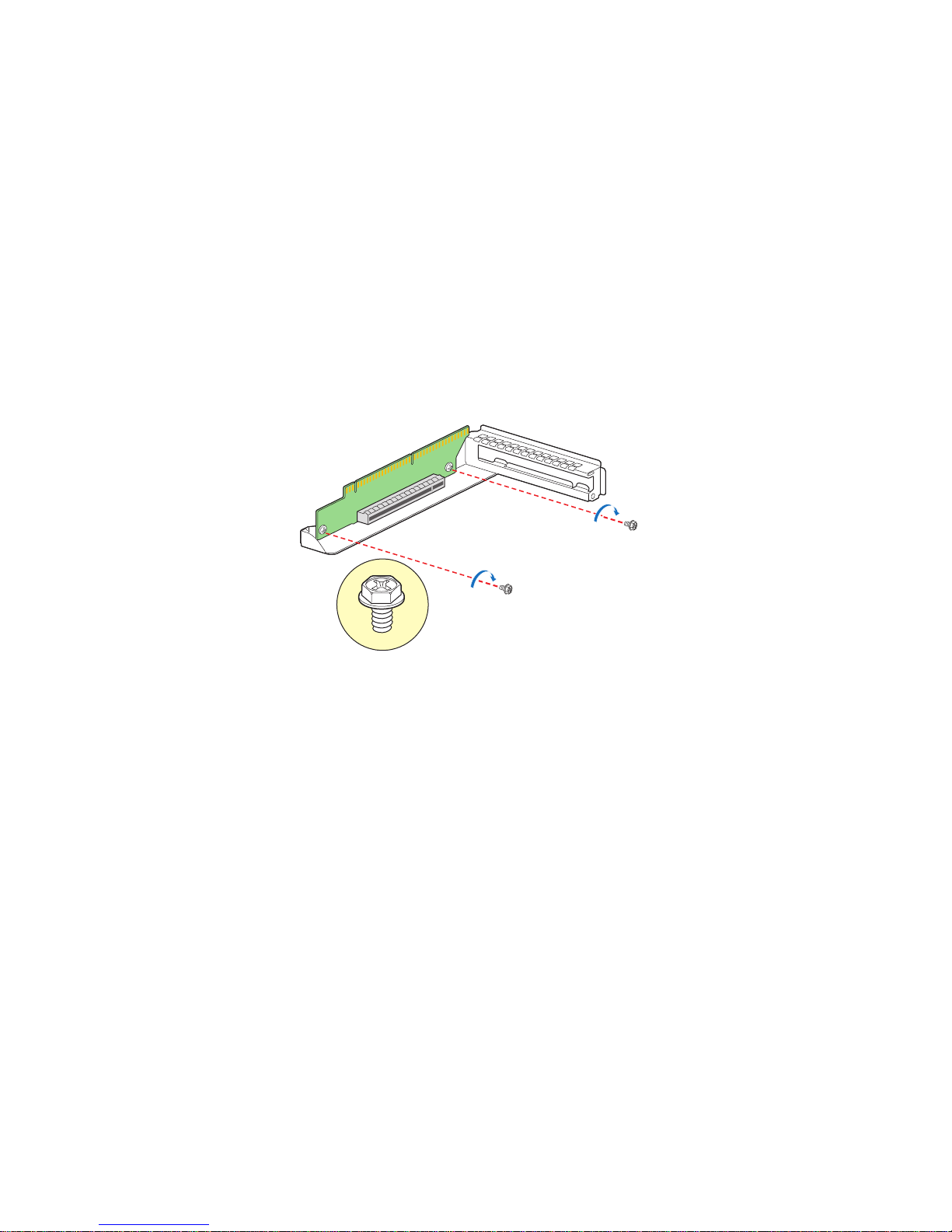
Installing the Replacement PCI Express* Riser Card
AF003041
To install the replacement PCI Express* riser card, follow these steps:
1. Disconnect any cables attached to any add-in cards.
2. Remove the PCI riser assembly. For instructions, see “Removing the PCI Riser
Assembly” on page 41.
3. Remove any add-in cards from the PCI riser connector. For instructions, see
“Removing a PCI Add-in Card” on page 45.
4. Position the riser card in the assembly such the holes on the card and the
assembly align.
5. Secure the riser card using two screws (see Figure 29).
Figure 29. Installing the Replacement PCI Express* Riser Card
6. Install the PCI add-in card(s) if desired. For instructions, see “Installing a PCI Add-
in Card” on page 44.
7. Install the PCI riser assembly into the server system. For instructions, see
“Installing the PCI Riser Assembly” on page 42.
8. Connect any cables to add-in cards that require them. See your add-in card
documentation for information and add-in card requirements.
Installing and Removing a PCI Add-in Card
The instructions below describe how to install and remove a PCI add-in card.
Installing a PCI Add-in Card
To install a PCI add-in card, follow these steps:
1. Remove the PCI riser assembly. For instructions, see “Removing the PCI Riser
Assembly” on page 41.
44 Intel® Server System SR1600UR Service Guide
Page 63

2. Remove the filler panel from the add-in card slot (see letter “A” in Figure 30).
3. Remove the screw (see letter “B” in Figure 30).
4. Insert add-in card until it seats in riser card connector (see letter “C” in Figure 30).
5. Secure the add-in card with screw (see letter “D” in Figure 30).
Riser Connector
Figure 30. Installing a Full-height Add-In Card
6. Install the PCI riser assembly into the server system. For instructions, see
“Installing the PCI Riser Assembly” on page 42.
Removing a PCI Add-in Card
To remove a PCI add-in card, follow these steps:
1. Remove the PCI riser assembly. For instructions, see “Removing the PCI Riser
Assembly” on page 41.
A
REMOVE Filler Panel
B
D
C
AF002853
2. Remove the screw securing the add-in card to the add-in card slot (see letter “A” in
Figure 31) .
3. Remove the PCI add-in card from the riser card connector (see letter “B” in
Figure 31).
Intel® Server System SR1600UR Service Guide 45
Page 64
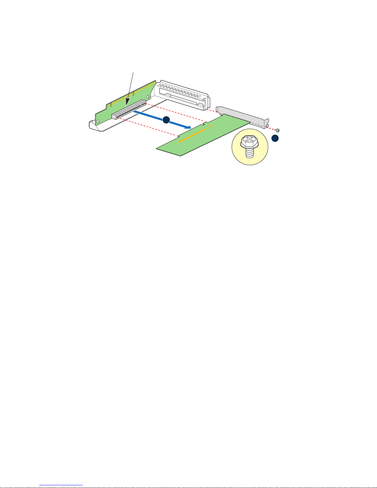
Figure 31. Removing a Full-height Add-In Card
Riser Connector
B
A
AF002854
Note: Make sure that the empty add-in card slot has the filler panel installed.
4. Install the PCI riser assembly into the server system. For instructions, see
“Installing the PCI Riser Assembly” on page 42.
Removing and Installing the Processor Air Duct
Always operate your server server system with the processor air duct in place. The air duct
is required for proper airflow within the server system.
For instructions on adding or replacing a processor, first remove the processor air duct,
and then see your server board user guide for instructions on processor installations and
removals. Return to these instructions to reinstall the processor air duct after installing
your processor and heatsink.
Removing the Processor Air Duct
To remove the processor air duct, follow these steps:
1. Remove the PCI riser assembly. For instructions, see “Removing the PCI Riser
Assembly” on page 41.
2. Lift the processor air duct from its location over the two processor sockets.
46 Intel® Server System SR1600UR Service Guide
Page 65

Figure 32. Removing the Processor Air Duct
Processor
Air Duct
AF002883
Installing the Processor Air Duct
Place the processor air duct over the processor socket(s) (see Figure 33). The front edge of
the air duct should align correctly with the notches on the fan module. Use caution not to
pinch or disengage cables that may be near or under the air duct.
AF002882
Installing and Removing Memory
The silkscreen on the board displays DIMM A1, DIMM A2, DIMM B1, DIMM B2,
DIMM C1, DIMM C2 for DIMMs on CPU socket 1 and DIMM D1, DIMM D2, DIMM
E1, DIMM E2, DIMM F1, DIMM F2 for DIMMs on CPU socket 2.
Intel® Server System SR1600UR Service Guide 47
Figure 33. Installing the Processor Air Duct
Page 66

Installing DIMMs
AF002884
DIMM B2
DIMM A1
DIMM A2
DIMM B1
DIMM C2
DIMM C1
DIMM F1
DIMM F2
DIMM E1
DIMM D2
DIMM D1
DIMM E2
D
A
B
E
C
To install DIMMs, follow these steps:
1. Remove the PCI riser assembly. For instructions, see “Removing the PCI Riser
Assembly” on page 41.
2. Remove the processor air duct. For instructions, see “Removing the Processor Air
Duct” on page 46.
3. Locate the DIMM sockets (see Figure 34).
Figure 34. Installing the Memory
4. Make sure the clips at either end of the DIMM socket(s) are pushed outward to the
open position (see letter “A” in Figure 34).
5. Holding the DIMM by the edges, remove it from its anti-static package.
48 Intel® Server System SR1600UR Service Guide
Page 67

6. Position the DIMM above the socket. Align the notch on the bottom edge of the
DIMM with the key in the DIMM socket (see letter “B” in Figure 34 - the arrow is
pointing to the key in the socket).
7. Insert the bottom edge of the DIMM into the socket.
8. When the DIMM is correctly positioned, push down on the top edge of the DIMM
until the retaining clips snap into place (see letter “C” in Figure 34).
9. Make sure the clips are firmly in place (see letter “D” in Figure 34).
Removing DIMMs
To remove a DIMM, follow these steps:
1. Remove the PCI riser assembly. For instructions, see “Removing the PCI Riser
Assembly” on page 41.
2. Remove the processor air duct. For instructions, see “Removing the Processor Air
Duct” on page 46.
3. Locate the DIMM sockets (see Figure 34).
4. Gently spread the retaining clips at each end of the socket. The DIMM lifts from
the socket.
5. Holding the DIMM by the edges, lift it from the socket, and store it in an anti-static
package.
Installing and Removing the Processor
Caution: Processor must be appropriate: You may damage the server board if you install a
processor that is inappropriate for your server. See “Additional Information and
Software” on pa ge 3 for a web link to the list of compatible processor(s).
Caution: ESD and handling pr ocessors: Reduce the risk of electrostatic dischar ge (ESD) damage to
the processor by doing the following: (1) Touch the metal chassis before touching the
processor or server board. Keep part of your body in contact with the metal chassis to
dissipate the static charge while handling the processor. (2) Avoid moving around
unnecessarily.
Caution: Pr otective socket cover needs to be r emoved for pr oper cooling of the pr ocessor; f ailur e to
remove the cover could result in damage to the system.
Installing the Processor
To install a processor, follow these instructions:
1. Remove the PCI riser assembly. For instructions, see “Removing the PCI Riser
Assembly” on page 41.
Intel® Server System SR1600UR Service Guide 49
Page 68

2. Remove the processor air duct. For instructions, see “Removing the Processor Air
AF002836
B
A
Duct” on page 46.
3. Remove the heatsink, if installed. For instructions, see “Removing the Heatsink” on
page 54.
4. Locate the processor socket.
5. Push the lever handle down and away from the socket to release it (see letter “A” in
Figure 35).
6. Rotate the lever open all the way (see letter “B” in Figure 35).
A
B
AF002835
Figure 35. Lifting the Processor Socket Lever
7. Push the rear tab with your finger tip to bring the front end of the load plate open
slightly (see letter “A” in Figure 36).
8. Open the load plate (see letter “B” in Figure 36).
9. Remove the protective socket cover (see Figure 37).
Note: Do not touch the orientation posts on the socket; they are very sensitive and easily
damaged.
Note: Retain the protective socket cover for use when removing a processor that will not be
replaced.
50 Intel® Server System SR1600UR Service Guide
Figure 36. Opening the Load Plate
Page 69

AF002837
AF002838
Figure 37. Removing the Protective Socket Cover
10. Remove the processor from the packaging box and remove the protective shipping
cover (see Figure 38).
Figure 38. Removing the Processor Protective Cover
11. Orient the processor with the socket such that the orientation notches on the
processor align with the two orientation posts on the socket, and insert the
processor into the socket (see Figure 39).
Intel® Server System SR1600UR Service Guide 51
Page 70

12. Close the CPU load plate all the way (see letter “A” in Figure 40).
A
AF002839
Orientation Notch
Orientation Post
A
B
AF002840
13. Close the socket lever completely and ensure that the load plate tab engages under
the socket lever when fully closed (see letter “B” in Figure 40).
14. Install the heatsink. For instructions, see “Installing the Heatsink” on page 52.
Installing the Heatsink
You must install the processor before installing the heatsink. For instructions, see
“Installing the Processor” on page 49.
Figure 39. Installing the Processor
Figure 40. Closing the Load Plate
Caution: Improper installation can damage the heatsink. Pay close attention to the steps and
perform each step exactly as indicated to avoid damage.
Caution: The heatsink has Thermal Interface Material (TIM) located on the bottom of it. Use
caution when you unpack the heatsink so you do not damage the TIM.
Note: New unused heatsinks have adequate TIM on the bottom. If you are reusing a heatsink
from replacing a processor, make sure there is adequate TIM present on the heatsink to
support processor cooling.
52 Intel® Server System SR1600UR Service Guide
Page 71

To install the heatsink, follow these steps:
1. Remove the protective film on the TIM, if present.
2. Orient the heatsink over the processor as shown in Figure 41. The heatsink fins
must be positioned as shown to provide correct airflow through the system.
3. Set the heatsink over the processor, lining up the four captive screws with the four
posts surrounding the processor.
4. Loosely screw in the captive screws on the heatsink corners in a diagonal manner
according to the numbers shown in Figure 41 as follows:
a. Starting with the screw at location 1, engage the screw threads by giving it two
rotations in the clockwise direction and stop. (IMPORTANT: Do not fully
tighten.)
b. Proceed to the screw at location 2 and engage the screw threads by giving it two
rotations and stop.
c. Engage screws at locations 3 and 4 by giving each screw two rotations and then
stop.
d. Repeat steps 4a through 4c by giving each screw two rotations each time until all
screws are lightly tightened upto a maximum of 8 inch-lbs torque.
3
Air Flow
2
1
4
TIM
Chassis Front
AF002841
Figure 41. Installing the Heatsink (1U Passive Heatsink Shown)
Intel® Server System SR1600UR Service Guide 53
Page 72

Removing the Heatsink
To install or remove the processor, you must first remove the heatsink.
Caution: Improper removal can damage the heatsink. Pay close attention to the steps and perform
each step exactly as indicated to avoid damage.
To remove the heatsink, follow these steps:
1. Remove the PCI riser assembly. For instructions, see “Removing the PCI Riser
Assembly” on page 41.
2. Remove the processor air duct. For instructions, see “Removing the Processor Air
Duct” on page 46.
3. Loosen the four captive screws on the heatsink corners in a diagonal manner
according to the numbers shown in Figure 42 as follows:
a. Starting with the screw at location 1, loosen it by giving it two rotations in the
anticlockwise direction and stop. (IMPORTANT: Do not fully loosen.)
b. Proceed to the screw at location 2 and loosen it by giving it two rotations and
stop.
c. Loosen screws at locations 3 and 4 by giving each screw two ro tations and then
stop.
d. Repeat steps 3a through 3c by giving each screw two rotations each time until all
screws are loosened.
4. Do one of the following:
— If removing the heatsink for the first time, do the following:
i. Lift the heatsink from the board.
ii. Remove and discard the spacer (see letter “C” in Figure 42).
Note: The system is shipped with a spacer installed between the heatsink and the
processor socket to protect the socket protective cover. This spacer will need
to be removed and discarded before installing the processor.
— If a processor is already installed, do the following:
i. Twist the heatsink slightly to break the seal between the heatsink and the
processor.
ii. Lift the heatsink from the processor. If it does not pull up easily, twist the
heatsink again. Do not force the heatsink from the processor. Doing so
could damage the processor.
54 Intel® Server System SR1600UR Service Guide
Page 73

B
2
Removing the Processor
To remove the processor, follow these steps:
1. Remove the PCI riser assembly. For instructions, see “Removing the PCI Riser
Assembly” on page 41.
3
A
1
4
TIM
Discard to Install CPU
This Side Up
Figure 42. Removing the Heatsink
C
Discard to Install CPU
This Side Up
2. Remove the processor air duct. For instructions, see “Removing the Processor Air
Duct” on page 46.
3. Remove the heatsink. For instructions, see “Removing the Heatsink” on page 54.
4. Unplug the processor fan cable from the server board.
5. Open the processor socket lever (see Figure 35).
6. Open the CPU load plate (see Figure 36).
7. Remove the processor.
8. If installing a replacement processor, see “Installing the Processor” on page 49 for
instructions. Otherwise, install the protective socket cover over the empty processor
socket.
Intel® Server System SR1600UR Service Guide 55
Page 74
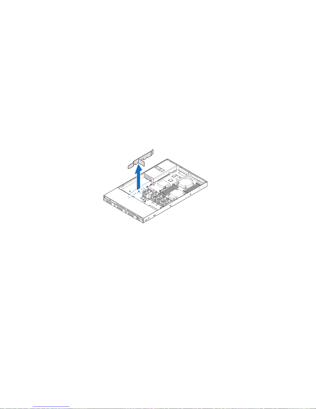
Removing and Installing the Small Air Baffle
AF002885
Some installation processes require that you remove the small air baffle that is placed
behind the hard drive bays, near the front of your server. The following sections describe
how to remove and then install the small air baffle. Use the steps in these sections only
when it is indicated as necessary for a component installation process.
Always operate your server system with the small air baffle in place. The small air baffle
is required for proper airflow within the server system.
Removing the Small Air Baffle
Pull up and out on the air baffle to remove it (see Figure 43).
Figure 43. Removing the Small Air Baffle
Installing the Small Air Baffle
To install the small air baffle, follow these steps:
1. Lower the baf fle into the server system and position the baffle over the two standof f
locations.
2. Snap the baffle into place as shown in Figure 44.
56 Intel® Server System SR1600UR Service Guide
Page 75
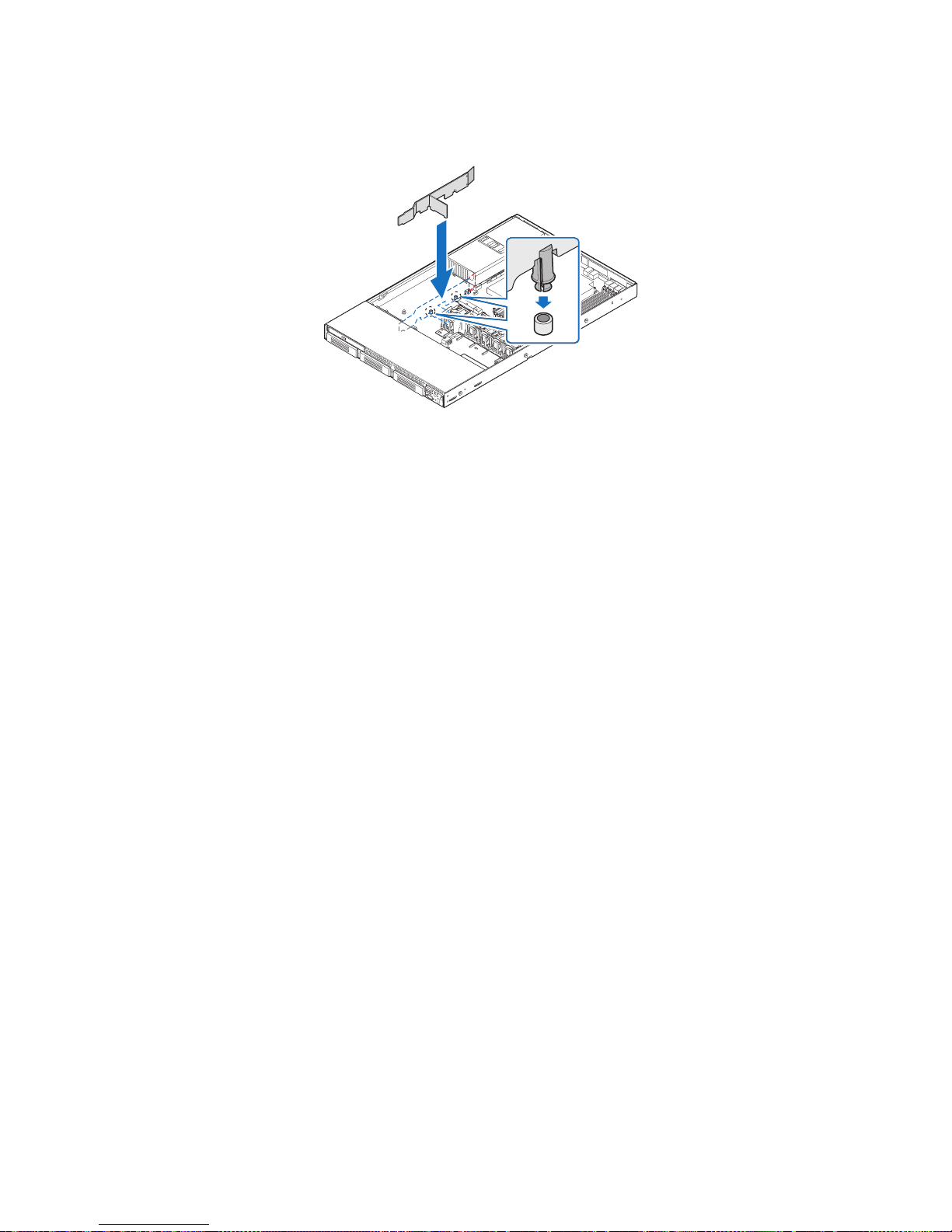
Figure 44. Installing the Small Air Baffle
AF002886
For information about cabling around the air baffle, see “Cable Routing” on page 30.
Installing and Removing a Fixed Mount Hard Drive
(Fixed Mount Hard Drive System Only)
Caution: Fixed moun t har d drives are NOT hot-swappable. Before removing or replacing the drive,
you must first take the server out of service, turn off all peripheral devices connected to
the system, turn off the system by pressing the power button, and unplug the AC power
cord from the system or wall outlet.
®
You can install up to three fixed SA TA hard drives in the Intel
(Product Code: SR1600UR).
Note: For a web link to a list of supported hardware, see “Additional Information and
Software” on pa ge 3.
Note: The fixed mount hard drives can be extracted only by accessing the drive carrier latch
from inside the chassis.
Server System SR1600UR
Installing a Fixed Mount Hard Disk Drive
To install a fixed mount hard disk drive, follow these steps:
1. Release the fixed mount drive carrier from the drive bay by pressing the blue carrier
latch (from inside the chassis) at the end of the black drive rail (see letter “A” in
Figure 45) and pushing it forward.
Intel® Server System SR1600UR Service Guide 57
Page 76

2. Slide the hard drive carrier out of the server system (see letter “B” in Figure 45).
Carrier Latch
AF003017
A
B
AF002380
Figure 45. Removing Fixed Mount Drive Carrier from the Server System
3. Remove the four screws securing the plastic retention device to the drive carrier
(see Figure 46). Store the plastic retention device for future use. Also, save the
screws; you need them to install the hard drive into the carrier.
Figure 46. Removing the Drive Blank from the Fixed Hard Drive Carrier
4. Remove the hard drive from its wrapper and place it on an antistatic surface.
5. Set any jumpers and/or switches on the drive according to the drive manufacturer's
instructions.
6. W ith the drive circuit-side down, position th e connector end of the drive so that it is
facing the rear of the drive carrier.
7. Align the holes in the hard disk drive to the holes in the drive carrier and attach it to
the carrier with the screws that were attached to the plastic retention device (see
Figure 47).
58 Intel® Server System SR1600UR Service Guide
Page 77
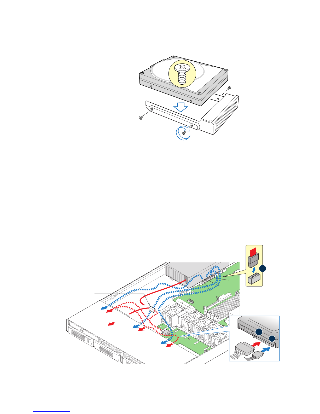
Figure 47. Installing Fixed Hard Drive into the Carrier
AF002381
SATA 0
SATA 1
SATA 2
Backplane
Fixed
Drive 1
Power
Supply
Cable
Connector
Back View of
SATA Drive
B
C
A
Fixed
Drive 2
Optical
Device
Fixed
Drive 0
AF003018
8. Slide the hard drive carrier into the server system until it clicks into place.
Note: All hard drive carriers must be installed in the server system and populated with either a
drive or a drive blank to maintain system thermals.
9. Connect on e e nd of th e SATA data cable(s ) to the SATA connector(s) on the server
board (see letter “A” in Figure 48).
10. Connect the opposite end of the SATA data cable(s) to the hard drive(s) (see letter
“B” in Figure 48).
11. Connect the SA TA power connector(s) to each installed hard drive (see letter “C” in
Figure 48).
Intel® Server System SR1600UR Service Guide 59
Power
Data
Page 78

Figure 48. Installing the Hard Drive Cables
AF002382
Removing a Fixed Mount Hard Disk Drive
To remove a fixed mount hard disk drive, follow these steps:
1. Disconnect all cables to the hard drive(s).
1. Release the fixed mount drive carrier from the drive bay by pressing the blue carrier
latch (from inside the chassis) at the end of the black drive rail (see letter “A” in
Figure 45) and pushing it forward.
2. Slide the hard drive carrier out of the server system (see letter “B” in Figure 45)
3. Remove the four screws that attach the hard drive to the carrier. Remove the drive
from the carrier and store the drive in an anti-static bag.
Figure 49. Removing Fixed Hard Drive from the Server System
4. Do one of the following:
— If you want to replace the hard drive, install the replacement drive using the four
screws you just removed. For instructions, see “Installing a Fixed Mount Hard
Disk Drive” on page 57.
— If the hard drive will not be replaced, install a drive blank into the carrier using
the four screws you just removed.
Note: To maintain proper system cooling, all hard drive carriers must be installed in the server
system and populated with either a drive or a drive blank.
5. Slide the hard drive carrier into the server system until it clicks into place.
60 Intel® Server System SR1600UR Service Guide
Page 79
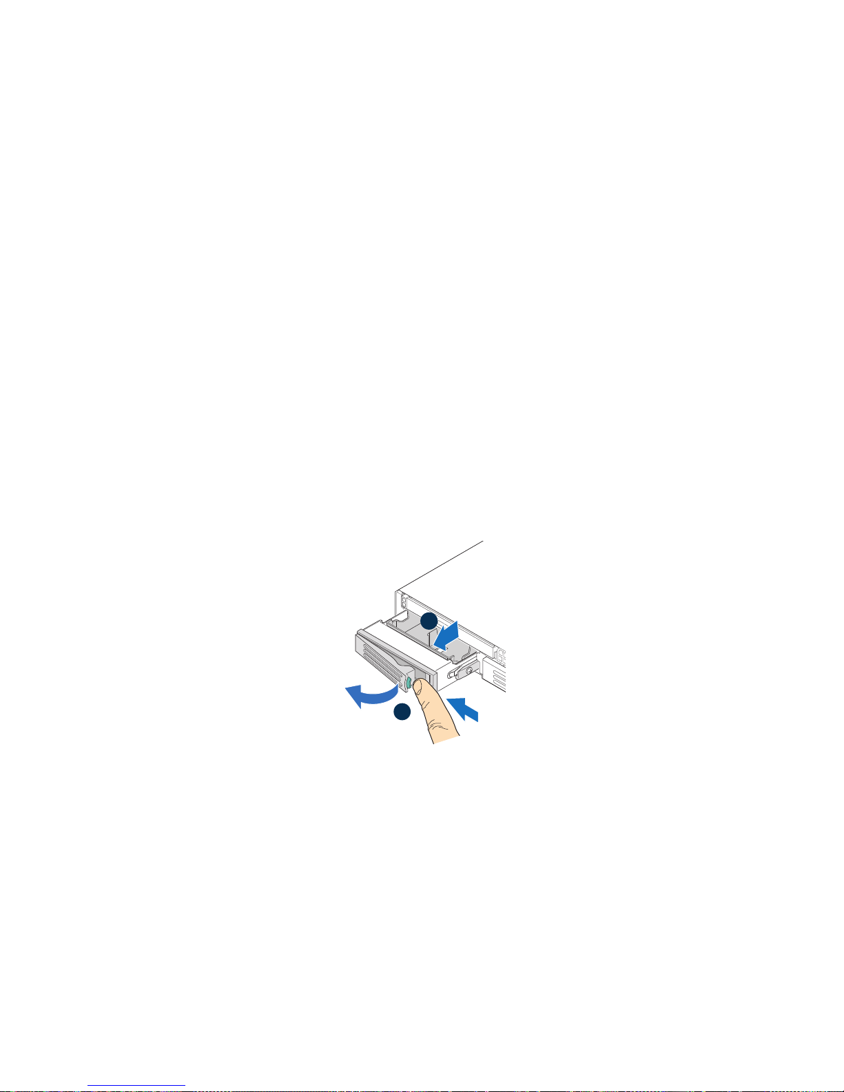
Installing and Removing a Hot-swap Hard Drive (Hot-
AF002943
A
B
swap Hard Drive System Only)
You may install up to three hot-swap SAS or SATA drives in the Intel® Server System
SR1600UR (Product Code: SR1600URHS).
Cautions: If you install less than three drives or devices, the empty drive bays must be occupied by
carriers with baffles to maintain proper system cooling.
To avoid possible damage to your server system, do not us e older style drive carriers.
Note: The server system does not support all hard drives. For a web link to a list of supported
hard drives, see “Additional Information and Software” on page 3”.
Installing a Hot-swap SAS or SATA Hard Disk Drive
To install a hot-swap SAS or SATA hard disk drive, follow these steps:
1. Press the green latch towards the black lever and pull out on the lever to release the
hard drive carrier (see letter "A" in Figure 50).
2. Slide the carrier from the server system (see letter "B" in Figure 50).
Figure 50. Removing Hot-swap Disk Carrier from the Server System
3. Remove the four screws that attach the plastic retention device or the previously
installed hard drive to the drive carrier (see letter “A” in Figure 51). Remove the
plastic retention device (see letter “B” in Figure 51) and store it for future use.
Intel® Server System SR1600UR Service Guide 61
Page 80

B
A
AF002944
Figure 51. Removing Retention Device from Drive Carrier
4. Remove the hard drive from its wrapper and place it on an antistatic surface.
5. Set any jumpers and/or switches on the drive according to the drive manufacturer's
instructions.
6. W ith the drive circuit-side down, position th e connector end of the drive so that it is
facing the rear of the drive carrier.
7. Align the holes in the drive to the holes in the drive carrier and attach it to the
carrier with the screws that were attached to the plastic retention device.
AF002945
Figure 52. Installing Hard Drive into Carrier
8. With the carrier lever in the open position, slide the drive assembly into the server
system and push all the way until it stops (see letter “A” in Figure 53).
9. Close the lever to lock the drive assembly into place (see letter “B” in Figure 53).
A
B
AF002946
Figure 53. Installing Drive Assemby into the Server System
62 Intel® Server System SR1600UR Service Guide
Page 81

Removing a Hot-swap SAS or SATA Hard Disk Drive
To remove a hot-swap SAS/SATA hard disk drive, follow these steps:
1. Press the green latch towards the black lever and pull out on the lever to release the
hard drive carrier.
2. Slide the carrier from the server system.
3. Remove the four screws that attach the hard drive to the drive carrier. Lift the drive
from the carrier and store the drive in an anti-static bag.
4. Do one of the following:
— To install the replacement drive, see “Installing a Hot-swap SAS or SAT A Hard
Disk Drive” on page 61.
— If you are not installing a drive, place the plastic retention device into the drive
carrier and secure the device by inserting the four screws your removed from the
hard drive into the screw locations on the carrier.
Note: To maintain proper system cooling, all hard drive carriers must be installed in the server
system and populated with either a drive or a drive blank.
5. W ith the black lever in the fully open position, sl ide the drive carrier into the server
system and push all the way until it stops.
6. Close the lever to lock the drive carrier into place.
Installing and Removing a Slimline Optical Drive or
Internal USB Floppy
You can install a SATA optical drive in the slimline optical drive bay.
®
In the Intel
SR1600URHS), you can also install a slimline USB floppy drive. The USB floppy drive
can be inserted into either the slimline bay or hard drive bay directly below the slimline
bay .
Cautions: Slimline optical drives and USB floppy drives are NOT hot-swappable. Before removing
or replacing the drive, you must first take the server out of service, turn off all peripheral
devices connected to the system, turn off the system by pressing the power button, and
unplug the AC power cord from the system or wall outlet.
To maintain proper system cooling, a filler blank must be installed if you do not install a
device at this location.
Note: A USB Floppy drive is not supported in the Intel
mount hard drives (Product Code: SR1600UR).
For a web link to a list of supported hardware, see “Additional Information and
Software” on pa ge 3.
Server System SR1600UR with hot-swap hard drives (Product Code:
®
Server System SR1600UR with fixed
Intel® Server System SR1600UR Service Guide 63
Page 82

Installing a Slimline Optical Drive or Internal USB Floppy
To install a slimline optical drive or USB floppy, follow these steps:
1. Remove the slimline drive bay filler panel, if installed.
2. Obtain the optical drive and the drive tray.
3. Align the two holes on the left edge of the optical drive with the two metal tabs in
the tray (see letter “A” in Figure 54).
4. Lower the opposite side of the optical drive into the tray until it clicks into place
(see letter “B” in Figure 54).
A
Metal Tab
B
AF002887
Figure 54. Installing an Optical Drive into the Drive Tray
5. Pull the power and data cables through the front of the chassis opening (see letter
“A” in Figure 55).
6. Connect the cables to the rear of the optical device (see letter “B” in Figure 55).
7. From the back side of the device bay, pull the cables back into the chassis opening
as you insert the device. Push the device all the way from the front until it clicks
(see letter “C” in Figure 55).
8. Verify that the blue release lever on the tray (see letter “D” in Figure 55) locks into
place.
64 Intel® Server System SR1600UR Service Guide
Page 83

Optical
AF002889
Server Board
SATA Connectors
SATA Conn.
Detail
Power
Supply
A
Server Board
SATA Cable
A
Drive
B
Optical
Device Tray
Assembly
Power
Data
C
Optical
Device Tray
Assembly
Blue Release
Lever
D
AF002888
Figure 55. Installing an Optical Drive Assembly into the Server System
9. Connect the SATA end of the cable to one of the SATA connectors on the server
board (see letter “B” in Figure 56).
Intel® Server System SR1600UR Service Guide 65
Figure 56. Connecting the Optical Device Data Cable
Page 84

10. (Optional) For installing the optional USB floppy drive, note the location of the
Blue Release
Lever
A
B
AF002892
USB connector on the backplane and refer to the documentation that came with the
device.
Removing a Slimline Optical Drive or Internal USB Floppy
To remove the slimline optical drive or USB floppy, follow these steps:
1. If removing an internal USB floppy drive, unplug it from the backplane.
2. Disconnect the power and data cables from the rear of the optical device.
3. Press the blue release lever (from inside the chassis) to unlock the optical drive tray
and remove the slimline optical drive tray assembly from the server system (see
Figure 57).
Optical
Device Tray
Assembly
Figure 57. Removing the Slimline Optical Drive Assembly from the Server System
4. Press downward on the side of the tray (see letter “A” in Figure 58) and disengage
the drive from the two metal tabs on the opposite side of the tray (see letter “B” in
Figure 58).
5. Slide the optical drive out (see letter “C” in Figure 58) to remove it from the tray.
66 Intel® Server System SR1600UR Service Guide
Page 85

B
Metal Tab
C
A
AF002893
Figure 58. Removing the Slimline Optical Drive from the Tray
Filling Empty Server System Bays
You must install either a filler panel, drive blank, or empty drive carrier into an empty
drive bay. To access the drive bays, remove the front bezel if it is installed. For
instructions, see “Removing the Front Bezel” on page 38.
With the bezel removed, install the appropriate panel(s), blank, or empty hard drive bay(s)
as follows:
• If you do not have an optical drive or floppy drive installed in the slimline bay,
install the slimline filler panel.
• If you do not have a hard drive installed, install the drive blank into the hard drive
carrier.
• Install empty hard drive carriers into any remaining empty hard drive bays.
Intel® Server System SR1600UR Service Guide 67
Page 86

Installing and Removing the I/O Expansion Module
Installing the I/O Expansion Module
To install the I/O expansion module, follow these steps:
1. Remove the PCI riser assembly. For instructions, see “Removing the PCI Riser
Assembly” on page 41.
2. Remove the processor air duct. For instructions, see “Removing the Processor Air
Duct” on page 46.
3. Squeeze the sides of the I/O expansion module filler panel(s) to disengage it from
the server system back panel and remove it (see letter “A” in Figure 59).
Note: If you are installing an I/O expansion module that uses only one slot, remove the filler
panel only from the slot shown so that the module can be attached to I/O connector 1. Do
not remove the filler panel from the second slot.
4. Attach the standoffs to the server board by pressing into the holes (see letter “B” in
Figure 59).
Note: For the 1-socket expansion module, install the three standoffs shown in gray. For the 2-
socket expansion module, also install the fourth standoff shown in red..
5. Position the I/O expansion module over the server board as shown in Figure 59.
6. First fit the front of the module into the back panel slot(s), and then attach the
module to the server board connector and engage the standoffs (see letter “C” in
Figure 59).
68 Intel® Server System SR1600UR Service Guide
Page 87

2-Socket
I/O Exp. Module
1-Socket
I/O Exp. Module
A
Snap
Standoff
C
B
Standoff
Hole
Server Board
I/O Connector 1
Figure 59. Installing the I/O Expansion Module to the Server System
7. Install the processor air duct. For instructions, see “Installing the Processor Air
Duct” on page 47.
8. Install the PCI riser assembly into the server system. For instructions, see
“Installing the PCI Riser Assembly” on page 42.
Removing the I/O Expansion Module
To remove the I/O expansion module, follow these steps:
1. Remove the PCI riser assembly. For instructions, see “Removing the PCI Riser
Assembly” on page 41.
Filler Panels
AF002855
2. Remove the processor air duct. For instructions, see “Removing the Processor Air
Duct” on page 46.
3. Disconnect the I/O expansion module from the server board connector and the
standoffs and remove the module out of the server system (see letter “A” in
Figure 60).
4. Remove the standoffs from the server board (see letter “B” in Figure 60).
Intel® Server System SR1600UR Service Guide 69
Page 88

5. Install the I/O expansion module filler panel(s) into the system back panel (see
1-Socket
I/O Exp. Module
Standoff
Hole
2-Socket
I/O Exp. Module
Server Board
Connector
Filler Panels
Snap
Standoff
AF002856
B
A
C
letter “C” in Figure 60).
Figure 60. Removing the I/O Expansion Module from the Server System
6. Install the processor air duct. For instructions, see “Installing the Processor Air
Duct” on page 47.
7. Install the PCI riser assembly into the server system. For instructions, see
“Installing the PCI Riser Assembly” on page 42.
Installing and Removing the Intel® Remote
Management Module 3
Installing the Intel® RMM3
To install Intel® Remote Management Module 3, follow these steps:
1. Remove the PCI riser assembly. For instructions, see “Removing the PCI Riser
Assembly” on page 41.
2. Remove the processor air duct. For instructions, see “Removing the Processor Air
Duct” on page 46.
70 Intel® Server System SR1600UR Service Guide
Page 89
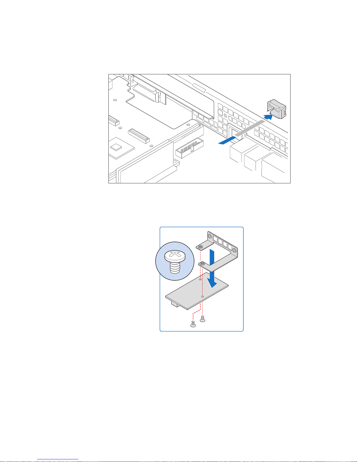
3. Squeeze the sides of the Intel® RMM3 filler panel to disengage it from the server
AF002997
Top View
AF002948
system back panel and remove it (see Figure 61).
Figure 61. Removing the Intel
4. Attach the Intel
®
RMM3 to the module bracket with two screws (see Figure 62).
Figure 62. Installing the Intel
5. Connect one end of the cable (labeled ‘RMM3’) to the RMM3 connector on the
®
Intel
RMM3 (see Figure 63).
®
RMM3 filler panel
®
RMM3 to the bracket
Intel® Server System SR1600UR Service Guide 71
Page 90
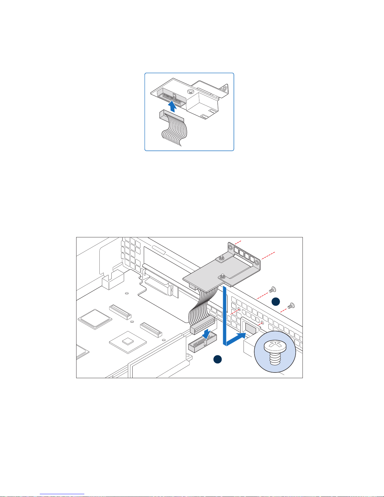
Note: Cable connectors are keyed and can only go in one way.
Bottom
AF002949
B
RMM3
Connector
A
RMM3 Module
AF002857
Figure 63. Connecting the Intel
®
6. Connect the opposite end of the cable to the RMM3 connector on the server board
(see letter “A” in Figure 64).
7. Attach the module bracket to the chassis with two screws (see letter “B” in
Figure 64).
Note: The screws install from the back of the chassis.
RMM3 cable
Figure 64. Installing the Intel
8. Install the processor air duct. For instructions, see “Installing the Processor Air
Duct” on page 47.
9. Install the PCI riser assembly into the server system. For instructions, see
“Installing the PCI Riser Assembly” on page 42.
72 Intel® Server System SR1600UR Service Guide
®
RMM3 to the Server System
Page 91

Removing the Intel® RMM3
To remove Intel® Remote Management Module 3, follow these steps:
1. Remove the PCI riser assembly. For instructions, see “Removing the PCI Riser
Assembly” on page 41.
2. Remove the processor air duct. For instructions, see “Removing the Processor Air
Duct” on page 46.
3. Remove screws from the back of the chassis (see letter “A” in Figure 65)
4. Disconnect the Intel
in Figure 65) and remove the module out of the server system (see letter “C” in
Figure 65).
®
RMM3 from the connector on the server board (see letter “B”
Figure 65. Removing the Intel
C
A
B
®
RMM3 from the Server System
AF002858
Intel® Server System SR1600UR Service Guide 73
Page 92

5. Install the Intel® RMM3 filler panel into the system back panel (see Figure 66).
AF002998
Figure 66. Installing the Intel
6. Install the processor air duct. For instructions, see “Installing the Processor Air
Duct” on page 47.
7. Install the PCI riser assembly into the server system. For instructions, see
“Installing the PCI Riser Assembly” on page 42.
®
RMM3 filler panel
Removing and Installing the Fan Board (Fixed Mount
Hard Drive System Only)
The Intel® Server System SR1600UR with fixed mount hard drives (Product Code:
SR1600UR) includes a fan board. The following sections describe how to replace the fan
board.
Removing the Fan Board
To remove the fan board, follow these steps:
1. Remove the PCI riser assembly. For instructions, see “Removing the PCI Riser
Assembly” on page 41.
2. Remove the processor air duct. For instructions, see “Removing the Processor Air
Duct” on page 46.
3. Disconnect all fan cables from the fan board.
4. Disconnect the power cable from the fan board (see letter “A” in Figure 67).
5. Remove the screw from the fan board (see letter “B” in Figure 67).
74 Intel® Server System SR1600UR Service Guide
Page 93
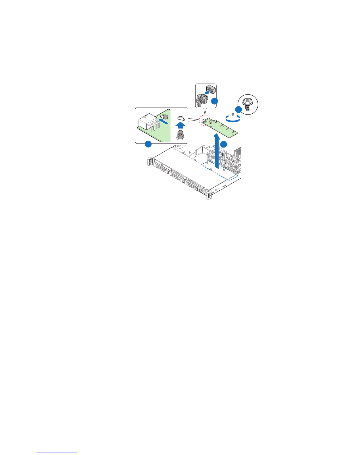
6. Hold the fan board only by the edges. Slide the fan board in the direction shown to
release it and lift it over the retention pins (see letter “C” in Figure 67).
7. Lift the fan board out of the server system (see letter “D” in Figure 67).
A
B
C
D
AF002905
Figure 67. Removing the Fan Board from the Server System
8. Install a replacement fan board. For instructions, see “Installing the Fan Board” on
page 76.
Intel® Server System SR1600UR Service Guide 75
Page 94
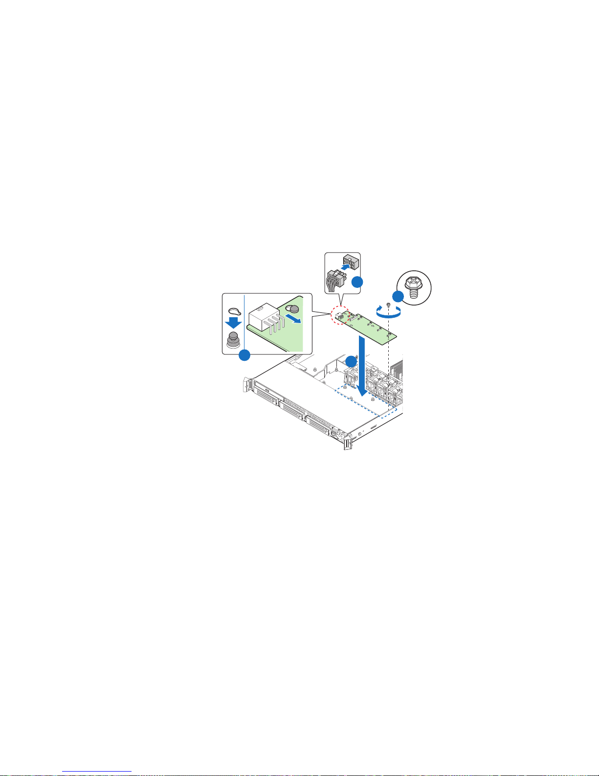
Installing the Fan Board
A
D
B
AF002906
C
To install the fan board, follow these steps:
1. Lower the fan board into the system (see letter “A” in Figure 68) and position the
fan board over the retention pins as shown.
2. Slide the fan board to the left (see letter “B” in Figure 68) to lock it in place and
install the screw (see letter “C” in Figure 68).
3. Connect the power cable to the power connector on the fan board (see letter “D” in
Figure 68).
Figure 68. Installing the Fan Board into the Server System
4. Connect the fan cables to the fan board.
5. Install the processor air duct. For instructions, see “Installing the Processor Air
Duct” on page 47.
6. Install the PCI riser assembly into the server system. For instructions, see
“Installing the PCI Riser Assembly” on page 42.
76 Intel® Server System SR1600UR Service Guide
Page 95

Installing and Removing the Backplane Board (Hotswap Hard Drive System Only)
The Intel® Server System SR1600UR with hot-swap drives (Product Code:
SR1600URHS) requires that you install a hot-swap backplane to make the system
operational. Two backplane options are supported:
• Active SAS RAID Backplane, capable of supporting SAS hard drives
• Passive SATA Backplane, capable of supporting SATA hard drives.
The steps for installing and replacing both the backplanes are nearly identical. Use the
following section for both backplane options. Where necessary, differences between the
two backplanes are noted.
Installing the Backplane Board
To install the backplane board, follow these steps:
1. Remove the PCI riser assembly. For instructions, see “Removing the PCI Riser
Assembly” on page 41.
2. Remove the processor air duct. For instructions, see “Removing the Processor Air
Duct” on page 46.
3. Lower the backplane board into the system and position the backplane board over
the six chassis standoffs (see letter “A” in Figure 69).
Note: Make sure that all the cables are seated over the backplane.
4. Press down uniformly until each standoff is inserted into the corresponding hole on
the backplane (see letter “B” in Figure 69).
5. Slide the backplane board in the direction shown (see letter “C” in Figure 69) to
lock it in place.
6. Secure the backplane with the thumbscrew (see letter “D” in Figure 69).
Intel® Server System SR1600UR Service Guide 77
Page 96

B
C
Active Backplane
D
A
AF002896
Figure 69. Installing the Backplane into the Server System
7. Install the bridge board as follows:
a. Open the retention clips on both ends (see letter “A” in Figure 70)
b. Insert the bridge board into the bridge board connector on the backplane and
server board (see letter “B” in Figure 70). Make sure that the connector edges on
both sides align correctly with the slots.
78 Intel® Server System SR1600UR Service Guide
Page 97
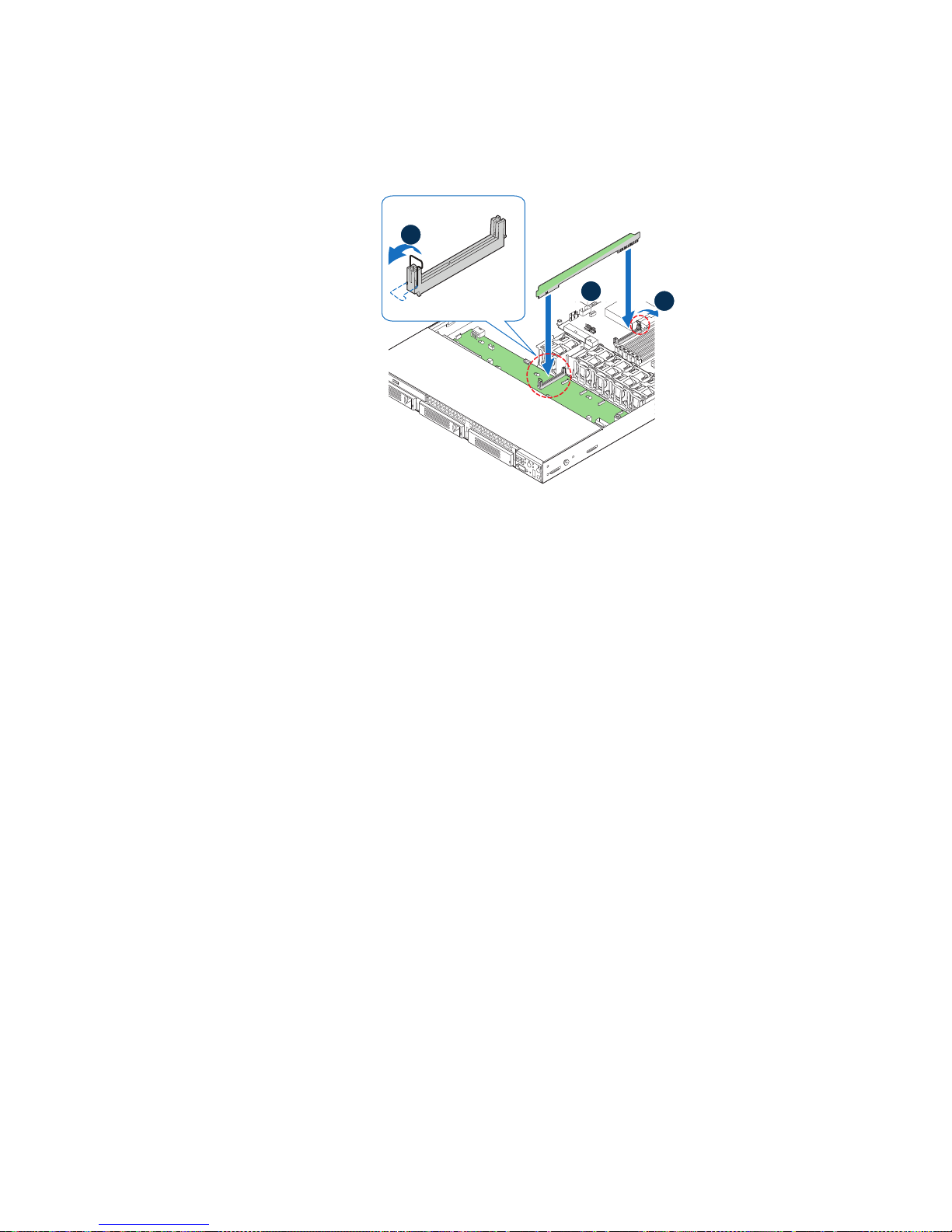
c. Close the retention clips on both ends (see letter “C” in Figure 70).
Server
Board
A
AF002897
A
B
Figure 70. Installing the Bridge Board
8. Connect the fan cables to the corresponding connectors on the backplane (s ee letter
“A” in Figure 71).
9. Connect the USB and data cables from the control panel to the USB connector and
front panel connector on the backplane (see letter “B” in Figure 71).
10. Connect the power cable to the power connector on the backplane (see letter “C” in
Figure 71).
11. Passive backplane only: Do the following:
Intel® Server System SR1600UR Service Guide 79
Page 98

a. Connect the hard drive SATA cables from either the server board or the add-in
AF002902
SATA 0
SATA 1
SATA 2
Passive
Backplane
Fan Connectors
B
C
Fan Module
A
SATA 0
SATA 1
SATA 2
SATA Conn.
Detail
D
D
SATA Conn.
Details
D
Server Board
USB
Cable
Data
Cable
card to the corresponding SATA connectors on the backplane (see letter “D” in
Figure 71 - connection from the server board shown).
Figure 71. Making Cable Connections
b. If you connect the SATA cables from the passive backplane to the add-in card,
also install the 3-pin white cable between the HBA connector on the backplane
and the add-in card to enable fault LED control.
Note: Do NOT connect the HBA cable in a system with an active backplane or when
using the SATA connectors on the server board to connect the hard drive SA TA
cables.
12. Install the processor air duct. For instructions, see “Installing the Processor Air
Duct” on page 47.
13. Install the PCI riser assembly into the server system. For instructions, see
“Installing the PCI Riser Assembly” on page 42.
80 Intel® Server System SR1600UR Service Guide
Page 99

Removing the Backplane Board
To remove the backplane board, follow these steps:
1. Remove the PCI riser assembly. For instructions, see “Removing the PCI Riser
Assembly” on page 41.
2. Remove the processor air duct. For instructions, see “Removing the Processor Air
Duct” on page 46.
3. Disconnect all cables from the backplane board.
4. Remove the bridge board by opening the retention clips from the backplane and the
server board (see letter “A” in Figure 72), and lifting straight up (see letter “B” in
Figure 72)
.
A
Server
Board
B
A
AF002903
Figure 72. Removing the Bridge Board from the Server System
5. Loosen the thumbscrew on the backplane board (see letter “A” in Figure 73).
6. Hold the backplane board only by the edges and slide the backplane board in the
direction shown to release it (see letter “B” in Figure 73).
Intel® Server System SR1600UR Service Guide 81
Page 100

7. Lift the backplane board from over the six standoffs (see letter “C” in Figure 73)
D
A
Active Backplane
B
AF002904
C
and out of the server system (see letter “D” in Figure 73).
Figure 73. Removing the Backplane from the Server System
8. Install a replacement backplane. For instructions, see “Installing the Backplane
Board” on page 77.
82 Intel® Server System SR1600UR Service Guide
 Loading...