

Page 1

Intel® Server System SR1560SF
Service Guide
A Guide for Technically Qualified Assemblers of Intel® Identified Subassemblies/
Products
Intel Order Number D92960-004
Page 2

Disclaimer
Information in this document is provided in connection with Intel® products. No license, express or implied, by
estoppel or otherwise, to any intellectual property rights is granted by this document. Except as provided in Intel's
Terms and Conditions of Sale for such products, Intel assumes no liability whatsoever, and Intel disclaims any
express or implied warranty, relating to sale and/or use of Intel products including liability or warranties relating to
fitness for a particular purpose, merchantability, or infringement of any patent, copyright or other intellectual property
right. Intel products are not designed, intended or authorized for use in any medical, life saving, or life sustaining
applications or for any other application in which the failure of the Intel product could create a situation where
personal injury or death may occur. Intel may make changes to specifications and product descriptions at any time,
without notice.
Intel server boards contain a number of high-density VLSI and power delivery components that need adequate
airflow for cooling. Intel's own chassis are designed and tested to meet the intended thermal requirements of these
components when the fully integrated system is used together. It is the responsibility of the system integrator that
chooses not to use Intel developed server building blocks to consult vendor datasheets and operating parameters to
determine the amount of airflow required for their specific application and environmental conditions. Intel Corporation
can not be held responsible if components fail or the server board does not operate correctly when used outside any
of their published operating or non-operating limits.
Intel, Intel Pentium, and Intel Xeon are trademarks or registered trademarks of Intel Corporation or its subsidiaries in
the United States and other countries.
* Other names and brands may be claimed as the property of others.
Copyright © 2010, Intel Corporation. All Rights Reserved
ii Intel® Server System SR1560SF Service Guide
Page 3

Intel® Server System SR1560SF Service Guide iii
Page 4

iv Intel® Server System SR1560SF Service Guide
Page 5

Preface
About this Manual
Thank you for purchasing and using the Intel® Server System SR1560SF.
This manual is written for system technicians who are responsible for troubleshooting,
upgrading, and repairing this server system. This document provides reference
information, feature information, and step by step instructions on how to add and replace
components on the server system. For the latest version of this manual, see
http://support.intel.com/support/motherboards/server/s5400sf.
Manual Organization
Chapter 1 provides a list of reference resources. In this chapter you will find a list of
technical documents that give additional details on the Intel
and the location where they can be found.
Chapter 2 provides a brief overview of the server system. In this chapter, you will find a
list of the server system features, illustrations of the product, and product diagrams to help
you identify components and their locations.
Chapter 3 provides instructions on adding and replacing components. Us e this chap ter for
step-by-step instructions and diagrams for installing or replacing components such as the
fans, power supply, drives, and other components.
Chapter 4 provides instructions on using the utilities that are shipped with the board or
that may be required to update the system. This includes how to navigate through the
BIOS Setup screens, how to perform a BIOS update, and how to reset the password or
CMOS. Information about the specific BIOS settings and screens is available in the Intel
Server Board S5400SF T echnical Product Specification. See “Server System References”
for a link to the Intel
At the back of this manual, you will find technical specifications, regulatory information,
"getting help" information, and the warranty.
®
Server Board S5400SF Technical Product Specification.
®
Server System SR1560SF,
®
Page 6

Product Contents
The Intel® Server System SR1560SF ships with the Intel® Server Board S5400SF. For
further information, see the following documents:
• Intel
• Intel
There are two versions of the Intel
and SR1560SFHS. The contents of each server system are listed below.
Intel® Server System SR1560SF - Product Code SR1560SF
Contents
Your Intel® Server System SR1560SF ships with the following items:
• Intel
• One 600 W power supply, installed in the server system
• A box of hardware components, referred to below as the "hardware box"
• PCIe* riser card assembly, installed in the server system
• Optical drive tray assembly (tray and interposer board), in hardware box
®
Server Board S5400SF Technical Product Specification
®
Server System SR1560SF Technical Product Specification
®
Server System SR1560SF: product codes SR1560SF
®
Server Board S5400SF, installed in the server system
• Optical drive cable, in hardware box
• Attention document, in the server system product box
• Quick Start User's Guide, in the server system product box
• One 32-6mm flat screw for installing the optical drive component, in the hardware
box
• Rack handles, in hardware box
• Slimline peripheral bay filler panel, in the hardware box
• Standard control panel module and cables (I/O and USB), installed in the server
system
• Two fixed mount drive trays and drive filler blanks, installed in the server system
• System fan board and fan board I/O cable, installed in the server system
• System fan assembly, including five dual-rotor fans, installed in the server system
• Two SATA cables, in hardware box
• Processor air duct, installed in the server system
• Blue plastic air baffle, installed in the server system
• Intel
• Intel
®
Server Deployment Toolkit 2.0 CD
®
System Management Software CD
vi Intel® Server System SR1560SF Service Guide
Page 7

Intel® Server System SR1560SF - Product Code
SR1560SFHS Contents
Your Intel® Server System SR1560SF ships with the following items:
• Intel
• One 600 W power supply, installed in the server system
• A box of hardware components, referred to below as the "hardware box"
• PCIe* riser card assembly, installed in the server system
• Optical drive tray assembly (tray and interposer board), in the hardware box
• Bridge board, in the hardware box
• Optical drive cable, in the hardware box
• Attention document, in the server system product box
• Quick Start User's Guide, in the server system product box
• One 32-6mm flat screw for installing the optical drive component, in the hardware
• Rack handles, in the hardware box
• Slimline peripheral bay filler panel, in the hardware box
• Standard control panel module and cable, installed in the server system
®
Server Board S5400SF, installed in the server system
box
• Three hot-swap drive trays and drive filler blanks, installed in the server system
• System fan assembly, including five dual-rotor fans, installed in the server system
• Processor air duct, installed in the server system
• Blue plastic air baffle, installed in the server system
• Intel
• Intel
Note: One of two hot-swap backplane kits must be ordered separately in order to make the
system operational. The following kits are available for purchase.
®
Server Deployment Toolkit 2.0 CD
®
System Management Software CD
• Passive hot-swap backplane. Order code: ASR1500PASBP
• Active hot-swap backplane. Order code: ASR1500SASBP
Intel® Server System SR1560SF Service Guide vii
Page 8

viii Intel® Server System SR1560SF Service Guide
Page 9

Safety Information
Important Safety Instructions
Read all caution and safety statements in this document before performing any of the
instructions. See also Intel Server Boards and Server Chassis Safety Information on the
®
Server Deployment Toolkit 2.0 CD and/or at
Intel
http://support.intel.com/support/motherboards/server/sb/cs-010770.htm.
Wichtige Sicherheitshinweise
Lesen Sie zunächst sämtliche Warnund Sicherheitshinweise in diesem Dokument, bevor
Sie eine der Anweisungen ausführen. Beachten Sie hierzu auch die Sicherheitshinweise zu
Intel-Serverplatinen und Servergehäusen auf der Intel
oder unter http://support.intel.com/support/motherboards/server/sb/cs-010770.htm.
®
Server Deployment T oolkit 2.0 CD
Consignes de sécurité
Lisez attention toutes les consignes de sécurité et les mises en garde indiquées dans ce
document avant de suivre toute instruction. Consultez Intel Server Boards and Server
Chassis Safety Information sur le Intel
rendez-vous sur le site
http://support.intel.com/support/motherboards/server/sb/cs-010770.htm.
®
Server Deployment Toolkit 2.0 CD ou bien
Instrucciones de seguridad importantes
Lea todas las declaraciones de seguridad y precaución de este documento antes de realizar
cualquiera de las instrucciones. Vea Intel Server Boards and Server Chassis Safety
Information en el Intel
http://support.intel.com/support/motherboards/server/sb/cs-010770.htm.
®
Server Deployment Toolkit 2.0 CD y/o en
Page 10

重要安全指导
在执行任何指令之前,请阅读本文档中的所有注意事项及安全声明。 和/或
http://support.intel.com/support/motherboards/server/sb/CS-010770.htm
上的 Intel
Server Boards and Server Chassis Safety Information(《Intel
服务器主板与服务器机箱安全信息》)。
x Intel® Server System SR1560SF Service Guide
Page 11

Warnings
Heed safety instructions: Before working with your server product, whether you are
using this guide or any other resource as a reference, pay close attention to the safety
instructions. You must adhere to the assembly instructions in this guide to ensure and
maintain compliance with existing product certifications and approvals. Use only the
described, regulated components specified in this guide. Use of other products /
components will void the UL listing and other regulatory approvals of the product and
will most likely result in noncompliance with product regulations in the region(s) in which
the product is sold.
System power on/off: The power button DOES NOT turn off the system AC power. To
remove power from system, you must unplug the AC power cord from the wall outlet.
Make sure the AC power cord is unplugged before you open the chassis, add, or remove
any components.
Hazardous conditions, devices and cables: Hazardous electrical conditions may be
present on power, telephone, and communication cables. Turn off the server and
disconnect the power cord, telecommunications systems, networks, and modems attached
to the server before opening it. Otherwise, personal injury or equipment damage can
result.
Electrostatic discharge (ESD) and ESD protection: ESD can damage disk drives,
boards, and other parts. We recommend that you perform all procedures in this chapter
only at an ESD workstation. If one is not available, provide some ESD protection by
wearing an antistatic wrist strap attached to chassis ground any unpainted metal surface on
your server when handling parts.
ESD and handling boards: Always handle boards carefully. They can be extremely
sensitive to ESD. Hold boards only by their edges. After removing a board from its
protective wrapper or from the server, place the board component side up on a grounded,
static free surface. Use a conductive foam pad if available but not the board wrapper. Do
not slide board over any surface.
Installing or removing jumpers: A jumper is a small plastic encased conductor that slips
over two jumper pins. Some jumpers have a small tab on top that you can grip with your
fingertips or with a pair of fine needle nosed pliers. If your jumpers do not have such a tab,
take care when using needle nosed pliers to remove or install a jumper; grip the narrow
sides of the jumper with the pliers, never the wide sides. Gripping the wide sides can
damage the contacts inside the jumper, causing intermittent problems with the function
controlled by that jumper. Take care to grip with, but not squeeze, the pliers or other tool
you use to remove a jumper, or you may bend or break the pins on the board.
Intel® Server System SR1560SF Service Guide xi
Page 12

xii Intel® Server System SR1560SF Service Guide
Page 13

Table of Contents
Preface ......................................................................................................................... v
About this Manual ..................................................................................................................v
Manual Organization .............................................................................................................. v
Product Contents .................................................................................................................. vi
Safety Information .....................................................................................................ix
Important Safety Instructions ................................................................................................ ix
Wichtige Sicherheitshinweise ............................................................................................... ix
Consignes de sécurité ..........................................................................................................ix
Instrucciones de seguridad importantes ............................................................................... ix
Chapter 1: Server System References ..................................................................... 1
Chapter 2: Server System Features ..........................................................................3
Cable Routing (Hot-Swap Drive System) ..............................................................................6
Cable Routing (Fixed Drive System) .....................................................................................7
Chassis Component Identification .........................................................................................8
Configuration Jumpers .........................................................................................................10
RAID Support ....................................................................................................................... 15
Front of Server System ........................................................................................................15
Peripheral Devices ...............................................................................................................18
Rack-Mounted Systems .......................................................................................................19
®
Intel
Server System SR1560SF - Product Code SR1560SF Contents ...................... vi
®
Server System SR1560SF - Product Code SR1560SFHS Contents ................ vii
Intel
Internal Components .....................................................................................................8
Standard Control Panel ...............................................................................................15
Bezels ..........................................................................................................................16
Hard Disk Drives ..........................................................................................................18
Slimline Optical Drive Carrier ......................................................................................19
Chapter 3: Hardware Installations and Upgrades .................................................21
Before You Begin ................................................................................................................. 21
Tools and Supplies Needed ........................................................................................21
System References .....................................................................................................21
Removing and Installing the Front Bezel .............................................................................21
Removing the Front Bezel ...........................................................................................22
Installing the Front Bezel .............................................................................................22
Removing and Installing the System Cover .........................................................................22
Removing the System Cover .......................................................................................22
Installing the System Cover .........................................................................................23
Removing and Installing the Processor Air Duct .................................................................24
Intel® Server System SR1560SF Service Guide xiii
Page 14

Removing the Processor Air Duct ............................................................................... 24
Installing the Processor Air Duct ................................................................................. 24
Installing and Removing Memory ........................................................................................ 25
Installing DIMMs .......................................................................................................... 27
Removing DIMMs ........................................................................................................ 27
Installing the Processor ............................................................................................... 28
Installing the Heat Sink(s) ........................................................................................... 29
Removing a Processor ................................................................................................ 30
Removing and Installing the Small Air Baffle ...................................................................... 30
Removing the Small Air Baffle .................................................................................... 31
Installing the Small Air Baffle ...................................................................................... 31
Installing and Removing a Hot-swap Hard Drive ................................................................. 32
Installing a SAS or SATA Hot-swap Hard Disk Drive .................................................. 32
Removing a SAS or SATA Hot-swap Hard Disk Drive ................................................ 33
Installing and Removing a Fixed Hard Drive ....................................................................... 34
Installing a Fixed Hard Disk Drive ............................................................................... 34
Removing a Fixed Hard Disk Drive ............................................................................. 35
Installing or Removing a Slimline Optical Drive ................................................................... 36
Installing a Slimline Optical Drive ................................................................................ 36
Removing a Slimline Optical Drive .............................................................................. 37
Filling Empty Server System Bays ...................................................................................... 38
Installing and Removing the PCI Riser Assembly ............................................................... 38
Removing the PCI Riser Assembly ............................................................................. 38
Installing the PCI Riser Assembly ............................................................................... 39
Installing and Removing a PCI Add-in Card ........................................................................ 40
Installing a PCI Add-in Card ........................................................................................ 40
Removing a PCI Add-in Card ...................................................................................... 40
Installing and Removing the I/O Expansion Module(s) ....................................................... 41
Installing the I/O Expansion Module(s) ....................................................................... 41
Removing the I/O Expansion Module(s) ..................................................................... 41
Installing and Removing the Intel
®
Remote Management Module 2 and the Intel® RMM 2 NIC
42
Installing the Intel
Removing the Intel
®
RMM2 and Intel® RMM2 NIC ....................................................... 42
®
RMM2 and Intel® RMM2 NIC ..................................................... 43
Installing/Replacing the Backplane Board (Hot-swap Drive System Only) ......................... 43
Installing the Backplane Board .................................................................................... 43
Removing the Backplane Board .................................................................................. 45
Replacing the Fan Board (Fixed Drive System Only) .......................................................... 46
Removing the Fan Board ............................................................................................ 46
Installing the Fan Board .............................................................................................. 47
Replacing the Server Board ................................................................................................ 47
Removing the Server Board ........................................................................................ 47
Installing the Server Board .......................................................................................... 49
Replacing the Backup Battery ............................................................................................. 50
xiv Intel® Server System SR1560SF Service Guide
Page 15

Replacing the Power Supply ................................................................................................51
Replacing the Control Panel Module (Hot-swap Drive System) ..........................................52
Replacing the Control Panel Module (Fixed Drive System) .................................................54
Replacing a System Fan ......................................................................................................55
Installing and Removing the Rack Handles .........................................................................57
Installing the Rack Handles .........................................................................................57
Removing the Rack Handles .......................................................................................57
Chapter 4: Server Utilities ........................................................................................59
Using the BIOS Setup Utility ................................................................................................59
Starting Setup ..............................................................................................................59
If You Cannot Access Setup ........................................................................................59
Setup Menus ...............................................................................................................59
Upgrading the BIOS .............................................................................................................61
Preparing for the Upgrade ...........................................................................................61
Upgrading the BIOS ....................................................................................................62
Clearing the CMOS ..............................................................................................................62
Resetting the Password .......................................................................................................63
Appendix A: Technical Reference .......................................................................... 65
600W Single Power Supply Input Voltages .........................................................................65
System Environmental Specifications ..................................................................................65
Appendix B: Intel® Server Issue Report Form .......................................................67
Appendix C: LED Decoder .......................................................................................71
Appendix D: Getting Help ........................................................................................77
World Wide Web .................................................................................................................. 77
Telephone ............................................................................................................................77
Appendix E: Regulatory and Compliance Information ......................................... 81
Product Regulatory Compliance ..........................................................................................81
Product Safety Compliance .........................................................................................81
Product Regulatory Compliance References ..............................................................82
Electromagnetic Compatibility Notices ................................................................................85
FCC Verification Statement (USA) ..............................................................................85
Industry Canada (ICES-003) .......................................................................................86
Europe (CE Declaration of Conformity) .......................................................................86
VCCI (Japan) ...............................................................................................................86
BSMI (Taiwan) .............................................................................................................86
Korean Compliance (RRL) ..........................................................................................87
Product Ecology Compliance ......................................................................................87
Regulated Spe
End-of-Life / Product Recycling ...........................................................................................92
cified Components ...............................................................................91
Intel® Server System SR1560SF Service Guide xv
Page 16

Appendix F: Warranty ...............................................................................................93
Limited Warranty for Intel® Chassis Subassembly Products .............................................. 93
Appendix G: Installation/Assembly Safety Instructions .......................................97
English ................................................................................................................................. 97
Deutsch ............................................................................................................................... 99
Français ............................................................................................................................. 101
Español ............................................................................................................................. 103
Chinese ............................................................................................................................. 106
Italiano ............................................................................................................................... 106
Appendix H: Safety Information ............................................................................109
English ............................................................................................................................... 109
Server Safety Information ......................................................................................... 109
Safety Warnings and Cautions .................................................................................. 109
Intended Application Uses ........................................................................................ 110
Site Selection ............................................................................................................ 110
Equipment Handling Practices .................................................................................. 110
Power and Electrical Warnings ................................................................................. 111
System Access Warnings ......................................................................................... 112
Rack Mount Warnings ............................................................................................... 112
Electrostatic Discharge (ESD) ................................................................................... 113
Other Hazards ........................................................................................................... 113
Deutsch ............................................................................................................................. 114
Sicherheitshinweise für den Server ........................................................................... 114
Sicherheitshinweise und Vorsichtsmaßnahmen ....................................................... 114
Zielbenutzer der Anwendung .................................................................................... 115
Standortauswahl ....................................................................................................... 115
Handhabung von Geräten ......................................................................................... 115
Warnungen zu Netzspannung und Elektrizität .......................................................... 116
Warnhinweise für den Systemzugang ....................................................................... 117
Warnhinweise für Racks ........................................................................................... 117
Elektrostatische Entladungen (ESD) ......................................................................... 118
Andere Gefahren ....................................................................................................... 118
Français ............................................................................................................................. 119
Consignes de securite sur le serveur ........................................................................ 119
Séurité: avertissements et mises en garde ............................................................... 119
Domaines d’utilisation prévus ................................................................................... 120
Sélection d’un emplacement ..................................................................................... 120
Pratiques de manipulation de l’équipement .............................................................. 121
Alimentation et avertissements en matiére d’électricité ............................................ 121
Avertissements sur le cordon d’alimentation ............................................................. 122
Avertissements sur l’accés au systéme .................................................................... 122
Avertissements sur le montage en rack .................................................................... 123
Décharges électrostatiques (ESD) ............................................................................ 124
xvi Intel® Server System SR1560SF Service Guide
Page 17

Autres risques ............................................................................................................124
Périphériques laser ....................................................................................................125
Español ..............................................................................................................................125
Información de seguridad del servidor ......................................................................125
Advertencias y precauciones sobre seguridad ..........................................................125
Aplicaciones y usos previstos ....................................................................................126
Seleccién de la ubicación ..........................................................................................126
Manipulacién del equipo ............................................................................................127
Advertencias de alimentacién y eléctricas .................................................................127
Advertencias sobre el cable de alimentación ............................................................127
Advertencias el acceso al sistema ............................................................................128
Advertencias sobre el montaje en bastidor ...............................................................129
Descarga electrostática (ESD) ..................................................................................130
Otros riesgos .............................................................................................................130
Intel® Server System SR1560SF Service Guide xvii
Page 18

xviii Intel® Server System SR1560SF Service Guide
Page 19

List of Figures
Figure 1. Intel® Server System SR1560SF ............................................................................... 3
Figure 2. Cable Routing for Hot-Swap Drive System................................................................ 6
Figure 3. Cable Routing for Fixed Drive System....................................................................... 7
Figure 4. System Components.................................................................................................. 8
Figure 5. Server Board Connector and Component Locations ................................................. 9
Figure 6. BIOS Select Jumper................................................................................................. 10
Figure 7. Recovery Jumpers ................................................................................................... 11
Figure 8. Light Guided Diagnostic LEDs ................................................................................. 12
Figure 9. Back Panel Connectors............................................................................................ 13
Figure 10. Active/Passive Backplane Components................................................................. 14
Figure 11. Standard Control Panel.......................................................................................... 16
Figure 12. Server System Back............................................................................................... 17
Figure 13. Optional Peripherals............................................................................................... 18
Figure 14. Removing the Front Bezel...................................................................................... 22
Figure 15. Installing the Front Bezel........................................................................................ 22
Figure 16. Removing the Server System Cover...................................................................... 23
Figure 17. Installing the Server System Cover........................................................................ 23
Figure 18. Removing the Processor Air Duct.......................................................................... 24
Figure 19. Removing the Processor 2 Air Dam (Optional - only if two processors are installed).
24
Figure 20. Installing the Processor Air Duct............................................................................ 25
Figure 21. Installing the Initial Four DIMMs............................................................................. 26
Figure 22. Installing the Memory............................................................................................. 27
Figure 23. Lifting the Processor Socket Handle...................................................................... 28
Figure 24. Installing the Processor.......................................................................................... 28
Figure 25. Removing the Socket Cover .................................................................................. 29
Figure 26. Installing the Heat Sink (1U Passive Heat Sink Shown) ........................................ 30
Figure 27. Removing the Small Air Baffle ............................................................................... 31
Figure 28. Installing the Small Air Baffle ................................................................................. 31
Figure 29. Removing Hot-swap Disk Carrier from the Server System.................................... 32
Figure 30. Removing Drive Blank from Drive Carrier.............................................................. 32
Figure 31. Installing Hard Drive into Carrier............................................................................ 33
Figure 32. Install Drive Assembly into the Server System ...................................................... 33
Figure 33. Removing the Drive Blank from the Fixed Hard Drive Carrier ............................... 34
Figure 34. Installing Fixed Hard Drive into the Carrier ............................................................ 35
Figure 35. Removing Fixed Hard Drive from the Server System ............................................ 35
Figure 36. Installing an Optical Drive into the Drive Tray........................................................ 36
Figure 37. Installing an Optical Drive Assembly into the Server System ................................ 37
Figure 38. Removing the Slimline Optical Drive Assembly from the Server System .............. 37
Figure 39. Removing the Slimline Optical Drive from the Tray ............................................... 38
Figure 40. Removing PCI Riser Assembly from the Server System ....................................... 39
Figure 41. Installing PCI Riser Assembly into the Server System........................................... 39
Intel® Server System SR1560SF Service Guide xix
Page 20

Figure 42. Installing a Full Height Add-In Card....................................................................... 40
Figure 43. Removing a Full Height Add-In Card..................................................................... 40
Figure 44. Installing the I/O Expansion Module to the Server Board...................................... 41
Figure 45. Removing the I/O Expansion Module(s) from the Server Board............................ 41
®
Figure 46. Installing the Intel
RMM2 and the Intel® RMM2 NIC Module to the Server System.
42
Figure 47. Removing the Intel
®
RMM and the Intel® RMM NIC Module from the Server System
43
Figure 48. Installing the Backplane into the Server System ................................................... 44
Figure 49. Installing the Bridge Board into the Server System ............................................... 44
Figure 50. Removing the Bridge Board from the Server System............................................ 45
Figure 51. Removing the Backplane from the Server System................................................ 46
Figure 52. Removing the Fan Board from the Server System................................................ 46
Figure 53. Installing the Fan Board into the Server System ................................................... 47
Figure 54. Removing the Server Board .................................................................................. 48
Figure 55. Installing the Server Board .................................................................................... 49
Figure 56. Replacing the Backup Battery ............................................................................... 51
Figure 57. Removing Power Supply from the Server System................................................. 52
Figure 58. Installing Power Supply into the Server System.................................................... 52
Figure 59. Removing the Control Panel Module (Hot-swap Drive System)............................ 53
Figure 60. Installing Control Panel Module into the Server System (Hot-swap Drive System) 53
Figure 61. Removing the Control Panel Module (Fixed Drive System) .................................. 54
Figure 62. Installing Control Panel Module into the Server System (Fixed Drive System)..... 55
Figure 63. Removing a Fan from the Fan Module .................................................................. 56
Figure 64. Installing a Fan into the Fan Module...................................................................... 56
Figure 65. Installing the Rack Handle..................................................................................... 57
Figure 66. Removing the Rack Handle................................................................................... 57
Figure 67. Clear CMOS Jumper ............................................................................................. 62
Figure 68. Password Reset Jumper........................................................................................ 63
Figure 69. Diagnostic LED Placement Diagram ..................................................................... 71
xx Intel® Server System SR1560SF Service Guide
Page 21

List of Tables
Table 1. Server System References .........................................................................................1
Table 2. Intel
Table 3. NIC LED Descriptions ...............................................................................................13
Table 4. Setup Menu Key Use ................................................................................................60
Table 5. System Environmental Specifications .......................................................................65
Table 6. POST Progress Code LED Example .........................................................................71
Table 7. Diagnostic LED POST Code Decoder .......................................................................72
Table 8. Product Regulatory Compliance Markings ................................................................82
Table 9. Product Ecology Compliance Markings .....................................................................88
Table 10. Other Markings ........................................................................................................90
®
Server System SR1560SF Feature Summary ...................................................4
Intel® Server System SR1560SF Service Guide xxi
Page 22

xxii Intel® Server System SR1560SF Service Guide
Page 23
1 Server System References
If you need more information about this product or information about the accessories that
can be used with this server system, use the following resources.
Table 1. Server System References
For this information or
software
For in-depth technical
information about the
server system, including
sub-system overviews
and mechanical drawings
For basic BIOS settings
and chipset information
For in-depth BIOS
information
For in-depth firmware
information on the
Baseboard Management
Controller (BMC)
For in-depth information
®
on Intel
Technology
I/O Acceleration
Use this Document or Software
®
Intel
Server System SR1560SF Technical Product Specification
Found at:
http://support.intel.com/support/motherboards/server/S5400SF/
and available on the Intel
Intel® Server Board S5400SF Technical Product Specification
Found at:
http://support.intel.com/support/motherboards/server/S5400SF/
and available on the Intel
®
Intel
Server Board S5400SF Technical Product Specification
Found at:
http://support.intel.com/support/motherboards/server/S5400SF/
®
Intel
5400 Chipset Server Board Family Server BIOS External
Product Specification
Found: available to order by contacting your Intel field
representative.
®
5400 Series Chipset-based Server Board Baseboard
Intel
Management Controller Firmware Core External Product
Specification
Found: available to order by contacting your Intel field
representative.
®
Intel
I/O Acceleration Technology Improves Intel Server Platform
Network Performance, Reliability, and Efficiency whitepaper
Found: available from your Intel field representative.
®
Server Deployment Toolkit 2.0 CD.
®
Server Deployment Toolkit 2.0 CD.
If you just received this
product and need to
install it
Accessories or other Intel
server products
Intel® Integrated Server System SR1560SF Quick Start User's
Guide
®
Found: in the product box and available on the Intel
Deployment Toolkit 2.0 CD.
Spares and Configuration Guide
Found: available from your Intel field representative or on the
Server Configurator Tool at http://indigo.intel.com/
serverconfiguratortool/default.aspx
Server
Page 24
Table 1. Server System References
For this information or
software
Hardware (peripheral
boards, adapter cards)
and operating systems
that have been tested with
this product
To make sure your system
falls within the allowed
power budget
For software to manage
your Intel
®
server
For diagnostics test
software
Use this Document or Software
Tested Hardware Operating Systems List
Found at:
http://support.intel.com/support/motherboards/server/S5400SF/
Power Budget Tool
Found at:
http://support.intel.com/support/motherboards/server/S5400SF/
®
System Management Software
Intel
Found: available on the Intel® System Management Software CD
that ships with your system.
Diagnostics: Platform Confidence Test (PCT)
Found at:
http://support.intel.com/support/motherboards/server/S5400SF/
and available on the Intel
®
Server Deployment Toolkit 2.0 CD.
2 Intel® Server System SR1560SF Service Guide
Page 25
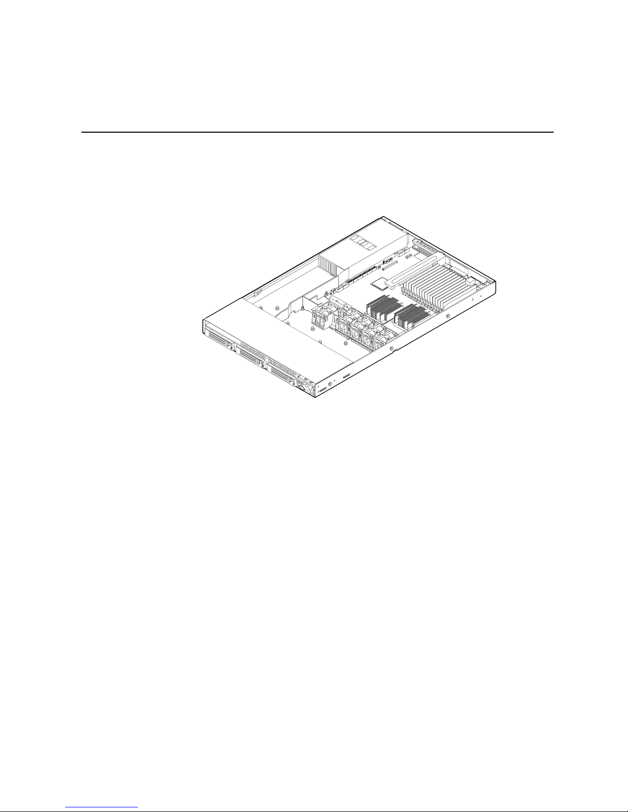
2 Server System Features
This chapter briefly describes the main features of the server system. This chapter
provides illustrations of the product, a list of the server system features, and diagrams
showing the location of important components and connections on the serv er system.
AF002374
Figure 1. Intel
®
Server System SR1560SF
Page 26
Table 2 summarizes the features of the server system.
®
Table 2. Intel
Feature Description
Server System SR1560SF Feature Summary
Dimensions
• 1.703 inches (43.25 mm) high
• 16.930 inches (430 mm) wide
• 27.25 inches (692 mm) deep
• 31 pounds (14.1 kg) - max chassis weight
®
Server Board Intel
Processor Support for up to two Multi-Core Intel
Server Board S5400SF
sequence.
For a complete list of supported processors, see:
http://support.intel.com/support/motherboards/server/
s5400sf/compat.htm
Memory Sixteen DIMM slots
• Support for stacked DDR2 667/800 MHz FBDIMM memory
Chipset Intel
Peripheral Interfaces External connections:
®
5400 Chipset, consisting of:
®
• Intel
• Intel
5400 Memory Controller Hub (MCH)
®
6321ESB I/O Controller Hub
• Stacked PS/2* ports for keyboard and mouse
• RJ45 Serial B port
• Two RJ45 NIC connectors for 10/100/1000 Mb connections
• Two USB 2.0 ports
• Optional 4-port external SAS expansion module,
OR
Optional NIC expansion module with two RJ45 NIC connectors
for 10/100/1000 Mbit/sec Ethernet LAN connectivity,
OR
Optional Infiniband* expansion module
Available Internal connections:
• One DH10 Serial A header
• Serial ATA (SATA) 150 connectors with integrated RAID 0/1
support
• One ATA-100 44-pin connector for optical drive support
• Optional support for SW RAID 5 with enablement key
• Optional Intel
• Optional Intel
®
Remote Management Module 2
®
Remote Management Module 2 NIC
®
Xeon® processors 5000
I/O Control National Semiconductor* PC87427 controller
Video On-board ATI* ES1000 video controller with 16 MB DDR SDRAM
4 Intel® Server System SR1560SF Service Guide
Page 27
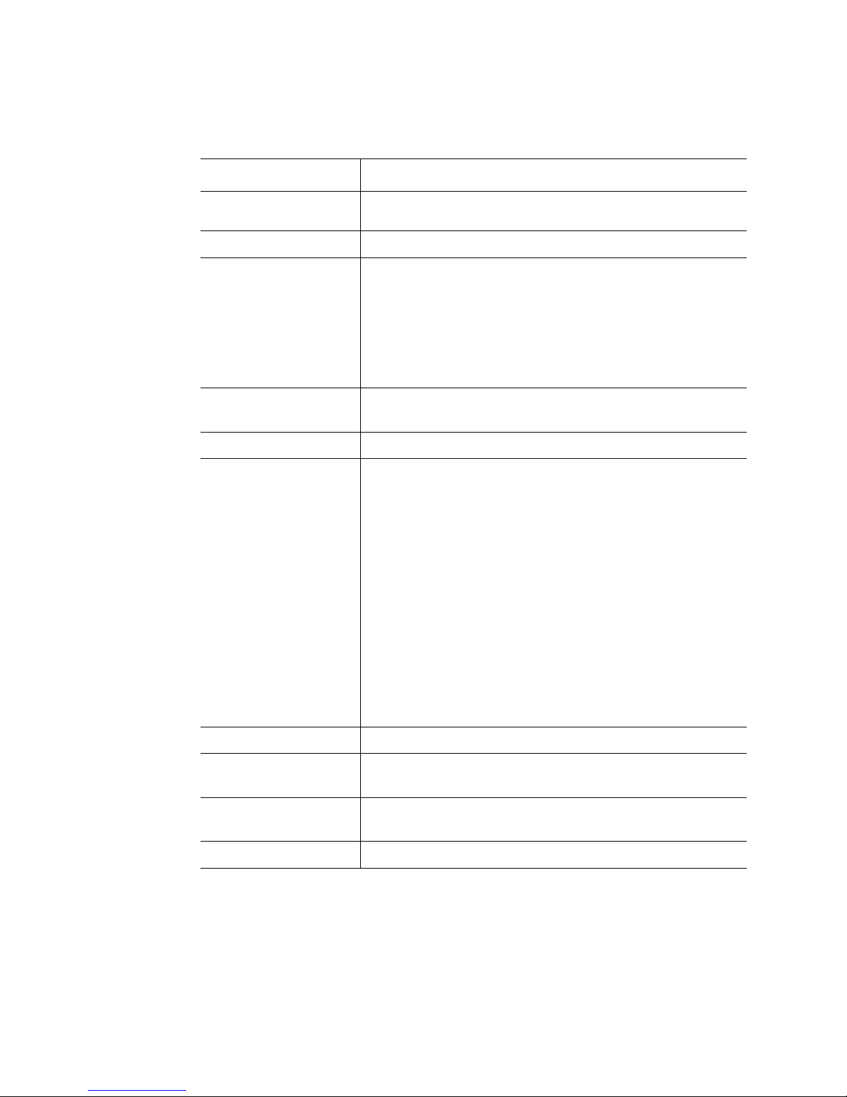
Table 2. Intel® Server System SR1560SF Feature Summary
Feature Description
LAN Intel
Ethernet LAN connectivity
®
82563EB dual port controller for 10/100/1000 Mbit/sec
Expansion Capabilities
Hard Drive Options
• One PCI Express* x16 GEN2 add-in card slot
• Fixed drive system:
– Two SATA drives
• Hot-swap drive system:
– Three SATA/SAS drives
®
• Intel
Embedded Server RAID Technology II with SW RAID
levels 0/1/10
• Optional support for SW RAID 5 with enablement key
Peripherals
• Slimline bay for IDE optical drive
• Optional USB floppy drive (product code SR1560SFHS)
Control Panel
LEDs and displays With standard control panel:
• Standard control panel
• NIC1 Activity
• NIC2 Activity
• Power / Sleep
• System Status
• System Identification
• Hard Drive Activity
Internal light guided diagnostics:
• Fan Fault
• Memory Fault
• CPU Fault
• 5VSB
• System Status
• System Identification
Power Supply Single 600 W power supply
Fans
USB
System Management Intel
Intel® Server System SR1560SF Service Guide 5
• Five non-redundant, monitored and controlled system fans
• Two non-redundant fans in power supply
• One front panel USB 2.0 port
• Two back I/O USB 2.0 ports
®
System Management Software
Page 28
Cable Routing (Hot-Swap Drive System)
When you add or remove components from your server system, make sure your cables are
routed correctly before reinstalling the server system cover. Use caution to make sure no
cables or wires are pinched and that the airflow from the fans is not blocked. Use the
figures below to determine the correct cable routing for a hot-swap drive system.
Intel® Remote Management
A
B
C
D
E
F
(optional)
Module
Intel® RMM NIC Module
I/O Module
Power Supply
Bridge Board
Backplane Board
(optional)
D
Power
Supply
I
J
(optional)
(passive shown)
B C
A
Server
Board
G
H
Power to Server Board
G
Power to Server Board
H
Power to Server Board
I
Power to Backplane Board (P3)
J
Control Panel USB
K
Control Panel Data
L
Fan Power Cables
M
E
CPU2
CPU1
Fan Module
(Aux. - P4)
(Main - P1)
(CPU - P2)
Figure 2. Cable Routing for Hot-Swap Drive System
6 Intel® Server System SR1560SF Service Guide
F
Optical
Drive
Module
Drive Bays
M
L
K
Control
Panel
Module
AF002352
Page 29
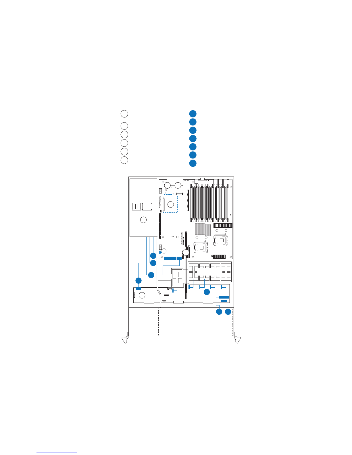
Cable Routing (Fixed Drive System)
When you add or remove components from your server system, make sure your cables are
routed correctly before reinstalling the server system cover. Use caution to make sure no
cables or wires are pinched and that the airflow from the fans is not blocked. Use the
figures below to determine the correct cable routing for a fixed drive system.
Power to Fan Board (P3)
I
Intel® Remote Management
A
(optional)
Module
Intel® RMM NIC Module
B
I/O Module
C
Power Supply
D
Fan Board
E
Power to Server Board
F
Power to Server Board
G
Power to Server Board
H
(optional)
B C
(optional)
(Aux. - P4)
(Main - P1)
(CPU - P2)
A
Fan Power Cables
J
Control Panel Data
K
Control Panel USB
L
Power to Fixed HDD
M
SATA Data to HDD 1
N
Power to Fixed HDD
O
SATA Data to HDD 0
P
Optical Drive Data
Q
D
Power
Supply
H
I
Q
Optical
Drive
Module
Server
Board
CPU1
F
G
NP
Drive Bays
CPU2
Fan Module
J
MO
E
K
L
Control
Panel
Module
AF002353
Figure 3. Cable Routing for Fixed Drive System
Intel® Server System SR1560SF Service Guide 7
Page 30
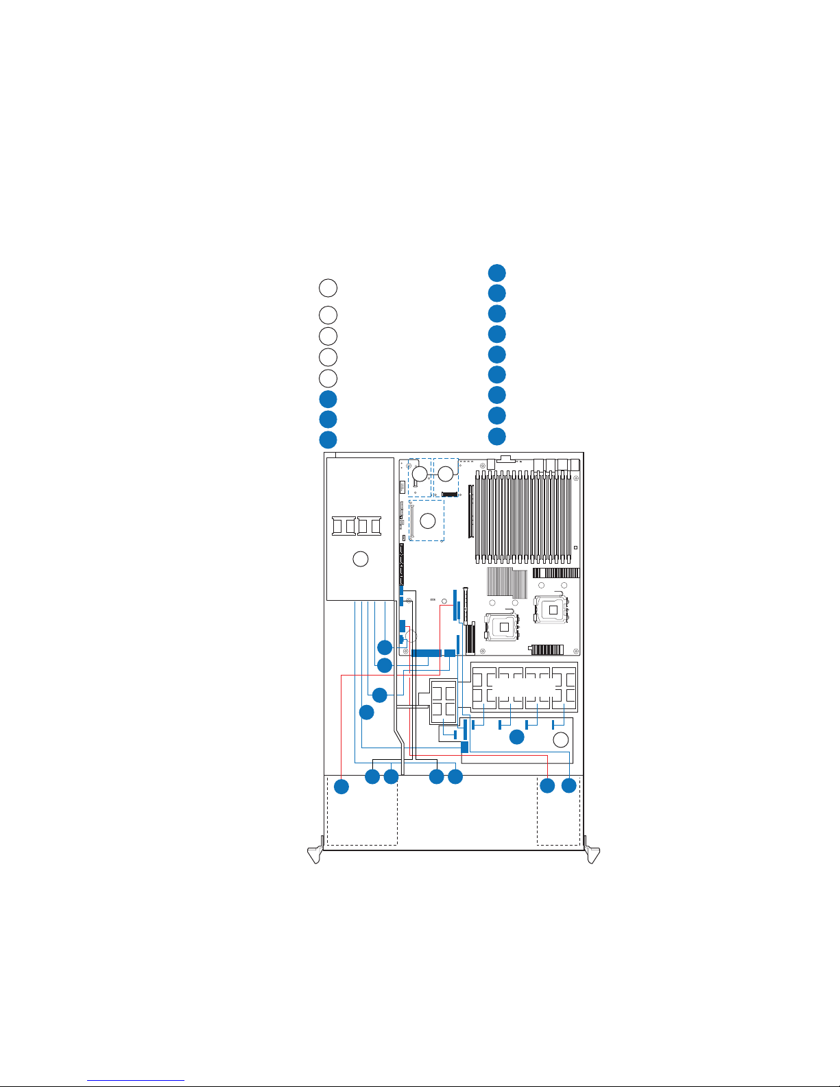
Chassis Component Identification
This section helps you identify the components of your server system. If you are near the
system, you can also use the Quick Reference Label provided on the inside of the chassis
cover to assist in identifying components.
Internal Components
C
B
A
M
D
E
F
G
L
H
K
J
A. Rack handles H. Fan module
B. Air baffle I. Fan board (fixed drive system) or
C. Power supply J. Control panel
D. Server board K. Hard drive bays; 2 - fixed drive system, 3 -
E. PCI card bracket (full height) L. Slimline Optical Drive Bay (drive not
F. PCI add-in riser assembly M. Front bezel (optional)
G. Processor air duct
A
backplane (hot-swap drive system)
hot-swap drive system (drives not
included)
included)
I
AF002186
Figure 4. System Components
8 Intel® Server System SR1560SF Service Guide
Page 31

Server Board Connector and Component
Locations
GFEDCBA
II
HH
GG
FF
EE
DD
BB
CC
AA
Z
Y
X
W
V
U
H
I
J
T
S
Q
O
R
P
LM
N
K
AF002159
A. Intel® RMM2 NIC Connector B. IO Module Option Connector C. POST Code Diagnostic LEDs
D. PCI Express* Riser Connector
E. System Identification LED - Blue F. Status LED - Green / Amber
(x16 Gen2)
G. External IO Connectors H. FBDIMM Memory Sockets I. Serial 'B' Port Configuration
Jumper
J. Processor 1 Socket K. Processor 2 Socket L. Bridge Board Connector
M. SSI 24-pin Control Panel Header N. Fan Board Connector O. CPU Power Connector
P. ATA-100 Optical Drive Connector
Q. Main Power Connector R. Battery
(Power+IO)
S. Power Supply Management
T. Dual Port USB 2.0 Header U. SATA0
Connector
V. SATA1
W. SATA 2
X. SATA 3
Y. SATA 4 Z. SATA 5 AA. SATA SW RAID 5 Activation Key
Connector
BB. Intel
®
Remote Management
CC. BMC FRU Update Jumper DD. CMOS Clear Jumper
Module 2 2 Connector
EE. Password Clear Jumper FF. Chassis Intrusion Switch Header GG. 3-pin IPMB Header
HH. 4-pin IPMB Header II. Serial 'A' Header
Figure 5. Server Board Connector and Component Locations
Intel® Server System SR1560SF Service Guide 9
Page 32

Configuration Jumpers
BIOS Select
J3H1
3
3
1-2: Force
Lower Bank
2-3: Normal
Operation (Default)
AF002171
Jumper Name Jumper Purpose
BIOS Select If pins 1-2 are jumpered, the BIOS in the lower bank will be selected
on the next reset. These pins should be jumpered on 2-3 for normal
operation.
Figure 6. BIOS Select Jumper
10 Intel® Server System SR1560SF Service Guide
Page 33

BMC Force
Update Mode
Disable
Enable
AF002170
Password
Reset
2
2
3
3
2
3
CMOS
Clear
Jumper Name Jumper Purpose
CMOS Clear If pins 2-3 are jumpered, the CMOS settings will be cleared on the
next reset. These pins should be jumpered on 1-2 for normal
operation. See “Clearing the CMOS” on page -62for complete
CMOS clear instructions.
Password Clear If pins 2-3 are jumpered, administrator and user passwords will be
cleared on the next reset. These pins should be jumpered on 1-2
for normal operation. See “Resetting the Password” on page -63 for
complete password reset instructions.
BMC Force Update Mode If pins 2-3 are jumpered, BMC Force Update Mode is enabled.
These pins should be jumpered on 1-2 for normal operation.
Figure 7. Recovery Jumpers
Intel® Server System SR1560SF Service Guide 11
Page 34

Intel® Light Guided Diagnostics
The server board contains numerous LEDs providing the following functions:
• Fault LEDs help identify failed and failing components. The fault LEDs turn on
(amber) if there is a memory or processor fault.
• The System Status LED that shows the over all health of the system (green, blinking
green, blinking amber, amber).
• POST Code Diagnostic LEDs change color or state (off, green, red, amber)
according to the POST sequence.
• The ID LED helps identify the server from among several servers. The ID LED is
off by default, and blue when activated by button or software.
• The 5V-STBY LED is always illuminated (green) when AC power is applied.
A
G
B
C
D
E
F
AF002160
A. POST Code Diagnostic LEDs E. CPU 2 Fault LED
B. ID LED F. CPU 1 Fault LED
C. Status LED G. 5VSB LED
D. Memory Fault LEDs
12 Intel® Server System SR1560SF Service Guide
Figure 8. Light Guided Diagnostic LEDs
Page 35

Back Panel Connectors
A
G
B
A. Mouse B. Keyboard
C. Serial Port B (RJ45) D. NIC 1 (10/100/1000 Mb)
E. NIC 2 (10/100/1000 Mb) F. Video
G. USB Port 6 H. USB Port 5
FC D E H
AF002161
Figure 9. Back Panel Connectors
The NIC LEDs at the right and left of each NIC provide the following information.
Table 3. NIC LED Descriptions
LED LED State Description
Left Off No network connection
Solid Amber Network connection in place
Blinking Amber Transmit/receive activity
Right Off 10 Mbps connection (if left LED is on or blinking)
Intel® Server System SR1560SF Service Guide 13
Solid Amber 100 Mbps connection
Solid Green 1000 Mbps connection
Page 36

SAS/SATA Backplanes
The hot-swap drive system can support either an active SAS backplane (Product Code ASR1500SASBP) or a passive SAS/SATA backplane (Product Code - ASR1500PASBP).
The backplanes provide the platform support for peripheral drives and hot-swap SAS or
SATA hard drives. To eliminate several cables, the backplanes are also used as a pathway
for signals from the server board to various platform interconnects, including those for the
control panel and peripheral drives.
The passive backplane acts as a 'pass-through' for the SAS/SATA data from the drives to
the SAT A controller on the server board or a SAS/SAT A controller add-in card. It provides
the physical requirements for the hot-swap capabilities. The active backplane has a builtin SAS controller that does not need communication with the baseboard controller or an
add-in card.
A
C
B
O
D
E
F
G
H
I
J
O
K
L
O
N
A. Backplane power I. Fan 3 power
B. Slimline USB J. Fan 2 power
C. SAS/SATA0 (passive backplane only) K. Fan 1 power
D. SAS/SATA1 (passive backplane only) L. Thumbscrew
E. SAS/SATA2 (passive backplane only) M. Control panel data
F. Fan 5 power N. Control panel USB
G. Bridge board connector O. HDD connectors
H. Fan 4 power
Figure 10. Active/Passive Backplane Components
M
AF002361
14 Intel® Server System SR1560SF Service Guide
Page 37

RAID Support
The Intel® Server System SR1560SF (product code SR1560SF) provides an embedded
SAT A controller that supports both 1.5 and 3.0 Gbps data transfer rates. The Intel
System SR1560SF (product code SR1560SFHS) provides SAS and SATA support. Both
systems can be configured for RAID 0, 1, and 10.
®
The Intel
Intel
For information on configuring RAID, see the RAID software user ’s guide that is
included on the Intel
Server System SR1560SF can be configured for SW RAID 5 by using the
®
RAID Activation Key AXXRAKSW5 accessory.
®
Server Deployment Toolkit 2.0 CD.
Front of Server System
Standard Control Panel
The diagram below shows the features of the standard control panel.
BA F GEDC
®
Server
H
I
L JK
AF002189
Callout Feature Function
A.
B.
C. Power/Sleep Button Powers on/off the system.
D. Power/Sleep LED Continuous green light indicates the system has power applied to
NIC 2 Activity LED
NIC 1 Activity LED
Continuous green light indicates a link between the system and
the network to which it is connected.
Blinking green light indicates network activity.
Puts the system in an ACPI sleep state.
it.
Blinking green indicates the system is in S1 sleep state.
No light indicates the power is off / is in ACPI S4 or S5 state.
Intel® Server System SR1560SF Service Guide 15
Page 38

Callout Feature Function
E. Hard Disk Drive
Activity LED
F. System Status LED Solid green indicates normal operation.
G. System Identification
LED
H. System Identification
Button
I. Reset Button Reboots and initializes the system.
J. USB 2.0 Port Allows you to attach a USB component to the front of the chassis.
K. NMI Button Puts the server in a halt-state for diagnostic purposes.
L. Video Port Allows you to attach a video monitor to the front of the chassis.
Random blinking green light indicates hard disk drive activity (SAS
or SATA).
No light indicates no hard disk drive activity.
Blinking green indicates degraded performance.
Solid amber indicates a critical or non-recoverable condition.
Blinking amber indicates a non-critical condition.
No light indicates POST is running or the system is off.
Solid blue indicates system identification is active.
No light indicates system identification is not activated.
Turns on/off the system identification LED.
The front and rear video ports cannot be used at the same time.
NOTE: Note: the video port option is only available on the hot-
swap drive system (product code SR1560SFHS).
Figure 11. Standard Control Panel
Bezels
The optional front bezel provides a snap-on design that allows for maximum airflow
through the server system. The bezel fits a system that has the standard control panel
installed (with or without a video port). The bezel provides a lock to secure the hard drive
and optical drive area. For instructions on installing the front bezel, see “Installing the
Front Bezel”.
The order number for the bezel is:
• ADWBEZBLACK: Black bezel for use with the standard control panel.
16 Intel® Server System SR1560SF Service Guide
Page 39

Rear of Server System
A B C
L
A. PS2 mouse connector G. USB 5 connector
B. PCI card bracket (full height) H. Video connector
C. AC Power Receptacle I. NIC 2 connector
D. Management Network Interface (optional) J. NIC 1 connector
E. IO module external connector (optional) K. RJ45 serial B port
F. USB 6 connector L. PS2 keyboard connector
I
JK
H FG DE
Figure 12. Server System Back
AF002187
Intel® Server System SR1560SF Service Guide 17
Page 40

Peripheral Devices
The server system provides locations and hardware for installing hard drives, a USB
floppy drive, and an optical drive. The drives must be purchased separately. The following
figure shows the available options.
A B
.
Hard Disk Drives
The fixed drive server system (product code SR1560SF) ships with three fixed mount
drive carriers. However, only the two left drive bays can be populated with SATA hard
drives. The third hard drive bay is not used in this system configuration.
The hot-swap drive server system (product code SR1560SFHS) ships with three hot-swap
drive carriers for installing three SAS or Serial ATA (SATA) drives.
The leftmost hard drive bay can be used to support a USB Floppy drive in the hot swap
drive system. To use the bay for a floppy drive, the AXXFLOPHDDTRAY accessory kit
must be used.
D C
AF002191
A. Slimline drive bay (drive not included)
B. Control panel
C. Hard drive status LEDs (hot-swap drives
only)
D. Hard drive bays (drives not included)
Figure 13. Optional Peripherals
Note: The USB floppy drive kit is supported on the Intel
code SR1560SFHS) only.
For instructions on installing hard drives, see “Installing and Removing a Fixed Hard
Drive” or “Installing and Removing a Hot-swap Hard Drive”.
Note: Drives can consume up to 17 watts of power each. Drives must be specified to run at a
maximum ambient temperature of 45C.
18 Intel® Server System SR1560SF Service Guide
®
Server System SR1560SF - (product
Page 41

Note: For a list of supported hard drives, see the Tested Hard Drive List at http://
support.intel.com/support/motherboards/server/s5400sf/compat.htm.
Slimline Optical Drive Carrier
The slimline optical drive carrier is used when installing an optional optical drive. One
slimline carrier is included with your server system; the optical drive must be purchased
separately.
The slimline optical drive carrier can only be inserted or removed when the system power
is turned off. Drives in the optical drive carrier are NOT hot-swappable. For installation
instructions on installing an optical drive, see “Installing or Removing a Slimline Optical
Drive”.
To use one of the drives provided by Intel, use the following order codes:
• Slimline CD-ROM Drive: AXXSCD
• Slimline DVD Drive: AXXDVDROM
• Slimline DVD/CDR Drive: AXXDVDCDR
Rack-Mounted Systems
Your Intel® Server System SR1560SF can be mounted into a rack. Intel provides three
options to mount this server into a rack. When installing the chassis into a rack, Intel
recommends you install systems from the bottom of the rack to the top. In other words,
install the first system in the rack into the bottom position of the rack, the second system
in the second position from the bottom, and so on. Instructions for installing your chassis
into a rack are included in each rackmount option kit.
Intel® Server System SR1560SF Service Guide 19
Page 42

20 Intel® Server System SR1560SF Service Guide
Page 43

3 Hardware Installations and
Upgrades
Before You Begin
Before working with your server product, pay close attention to the “Safety Information”
at the beginning of this manual.
Note: Whenever you service the system, you must first power down the server and unplug all
peripheral devices and the AC power cord.
Tools and Supplies Needed
• Phillips* (cross head) screwdrivers (#1 bit and #2 bit)
• Antistatic wrist strap and conductive foam pad (recommended)
System References
All references to left, right, front, top, and bottom assume the reader is facing the front of
the server system as it would be positioned for normal operation.
Removing and Installing the Front Bezel
The front bezel is available as an optional accessory for the Intel® Server System
SR1560SF. Bezel product code: ADWBEZBLACK.
Page 44

Removing the Front Bezel
Unlock the bezel and pull the bezel from the server system.
Figure 14. Removing the Front Bezel
Installing the Front Bezel
At each end of the bezel, line up the center notch on the bezel with the center guide on the
rack handles and push the bezel onto the front of the server system until it clicks into
place.
AF002373
Removing and Installing the System Cover
Removing the System Cover
The server system must be operated with the system cover in place to ensure proper
cooling. You will need to remove the top cover to add or replace components inside of the
server.
22 Intel® Server System SR1560SF Service Guide
AF002372
Figure 15. Installing the Front Bezel
Page 45
Note: A nonskid surface or a stop behind the server system may be needed to prevent the server
system from sliding on your work surface.
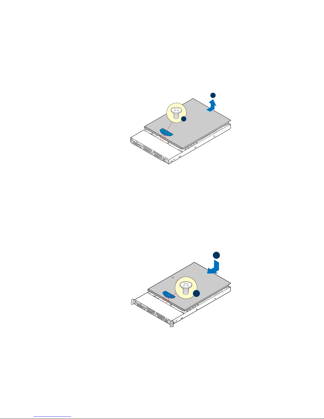
1. Remove the top cover screw (see letter “A”).
2. Slide the cover back until it stops and lift the cover upward to remove it (see letter
“B”).
Figure 16. Removing the Server System Cover
Installing the System Cover
B
A
AF002371
Place the cover over the server system so that the side edges of the cover sit just inside the
server system sidewalls.
1. Slide the cover forward until it clicks into place (see letter “A”).
2. Insert the screw at the center of the top cover (see letter “B”).
A
B
AF002370
Figure 17. Installing the Server System Cover
Intel® Server System SR1560SF Service Guide 23
Page 46

Removing and Installing the Processor Air Duct
Always operate your server system with the processor air duct in place. The air duct is
required for proper airflow within the server system.
Removing the Processor Air Duct
Lift the processor air duct from its location over the two processor sockets.
Figure 18. Removing the Processor Air Duct
Installing the Processor Air Duct
Turn processor air duct over to reveal underside. If two processors are installed: remove
air dam by rocking it back and forth until it snaps off.
Notes: Do not remove the air dam if only one processor is installed.
Figure 19. Removing the Processor 2 Air Dam (Optional - only if two
processors are installed)
AF002362
AF002366
24 Intel® Server System SR1560SF Service Guide
Page 47

Place the processor air duct over the processor sockets. The front edge of the air duct
should contact the fan module. Use caution not to pinch or disengage cables that may be
near or under the air duct.
AF002363
Figure 20. Installing the Processor Air Duct
Installing and Removing Memory
The silkscreen on the board for the DIMMs displays DIMM A1, DIMM A2, DIMM A3,
DIMM A4, DIMM B1, DIMM B2, DIMM B3, DIMM B4, DIMM C1, DIMM C2, DIMM
C3, DIMM C4, DIMM D1, DIMM D2, DIMM D3, and DIMM D4, starting from the
center of the board. See "Memory" for a discussion of the memory requirements and
options. See “Server System References” for a link to the list of tested DIMMs.
Figure 21 shows the supported DIMM configuration that is recommended because it
allows both memory branches from the MCH to operate independently and
simultaneously.
Intel® Server System SR1560SF Service Guide 25
Page 48

DIMM A3
DIMM A2
DIMM A1
DIMM A4
DIMM B1
DIMM B2
DIMM B3
DIMM C1
DIMM B4
DIMM C2
DIMM C4
DIMM C3
DIMM D1
DIMM D2
DIMM D3
DIMM D4
Channel A Channel D
Channel B Channel C
Branch 0 Branch 1
AF002164
Figure 21. Installing the Initial Four DIMMs
Notes: The initial four DIMMs installed must be populated in the blue slots: DIMM A1, DIMM
B1, DIMM C1, and DIMM D1.
Thermal requirement note: If x4 FBDIMMs are used, and the FBDIMMs do not have
thermal sensors, you must install DIMM Blanks when installing less than 8 FBDIMMs.
DIMM Blanks can be ordered through your preferred distributor.
26 Intel® Server System SR1560SF Service Guide
Page 49

Installing DIMMs
1. Make sure the clips at either end of the DIMM socket(s) are pushed outward to the
open position (see letter “A”).
2. Holding the DIMM by the edges, remove it from its anti-static package and
position the DIMM above the socket. Align the notch on the bottom edge of the
DIMM with the key in the DIMM socket. The arrow in the inset in Figure 22 is
pointing to the key in the socket (see letter “B”).
3. Insert the bottom edge of the DIMM into the socket (see letter “C”).
4. When the DIMM is inserted, push down on the top edge of the DIMM until the
retaining clips snap into place (see letter “D”).
5. Make sure the clips are firmly in place (see letter “E”).
E
D
C
B
A
AF002369
Figure 22. Installing the Memory
Removing DIMMs
Gently spread the retaining clips at each end of the socket. Holding the DIMM by the
edges, lift it from the socket, and store it in an anti-static package.
Installing or Replacing the Processor
Caution: Processor must be appropriate: You may damage the server board if you install a
processor that is inappr opriate for your server. See “Server System References” for a link
to the list of compatible processor(s).
Caution: ESD and handling pr ocessors: Reduce the risk of electrostatic dischar ge (ESD) damage to
the processor by doing the following: (1) Touch the metal chassis before touching the
processor or server board. Keep part of your body in contact with the metal chassis to
dissipate the static charge while handling the processor. (2) Avoid moving around
unnecessarily.
Intel® Server System SR1560SF Service Guide 27
Page 50

Installing the Processor
1. Locate the processor socket and raise the socket handle completely (see Figure 23).
Figure 23. Lifting the Processor Socket Handle
2. Raise the CPU load plate (see Figure 24).
TP02074
A
B
TP02075
Figure 24. Installing the Processor
Note: Do not touch the socket pins; they are very sensitive and easily damaged.
28 Intel® Server System SR1560SF Service Guide
Page 51

3. Line up the alignment marks on the processor and the socket, and insert the
processor into the socket.
A
B
TP02084
Note: Make sure the alignment triangle mark and the alignment triangle cutout align correctly.
4. Remove the protective socket cover (see Figure 25).
Caution: Pr otective socket cover needs to be r emoved for pr oper cooling of the pr ocessor; f ailur e to
remove the cover could result in damage to the system.
Note: Retain the protective socket cover for use when removing a processor that will not be
replaced.
A
B
TP02076
5. Lower the CPU load plate and lower the socket lever completely.
Installing the Heat Sink(s)
The heat sink has Thermal Interface Material (TIM) located on the bottom of it. Use
caution when you unpack the heat sink so you do not damage the TIM.
Note: New unused heat sinks have adequate TIM on the bottom. If you are re-using a heat sink
from replacing a processor, make sure there is adequate TIM present on the heat sink to
support processor cooling.
1. Set the heat sink over the processor, lining up the four captive screws with the four
posts surrounding the processor.
2. Loosely screw in the captive screws on the heat sink corners in a diagonal manner.
Do no fully tighten one screw before tightening another.
Intel® Server System SR1560SF Service Guide 29
Figure 25. Removing the Socket Cover
Page 52

3. Gradually and equally tighten each captive screw until each is firmly tightened.
Figure 26. Installing the Heat Sink (1U Passive Heat Sink Shown)
Removing a Processor
1. Loosen the four captive screws on the corners of the heat sink.
2. Twist the heat sink slightly to break the seal between the heat sink and the
processor.
3. Lift the heat sink from the processor. If it does not pull up easily , twist the heat sink
again. Do not force the heat sink from the processor. Doing so could damage the
processor.
3
2
4
1
AF002386
4. Lift the processor lever.
5. Raise the CPU load plate.
6. Remove the processor.
Removing and Installing the Small Air Baffle
Some installation processes will require that you remove the small air baffle that is placed
behind the hard drive bays, near the front of your server. The steps below describe how to
remove and then install the small air baffle. Use these steps only when it is necessary for a
component installation process.
30 Intel® Server System SR1560SF Service Guide
Page 53

Always operate your server system with the small air baffle in place. The small air baffle
is required for proper airflow within the server system.
Removing the Small Air Baffle
Pull up on the air baffle to remove it.
Figure 27. Removing the Small Air Baffle
AF002364
Installing the Small Air Baffle
Lower the baffle into the server system and position baffle over the two stand-off
locations. Press into place as shown in the figure below.
Figure 28. Installing the Small Air Baffle
AF002365
Intel® Server System SR1560SF Service Guide 31
Page 54

Installing and Removing a Hot-swap Hard Drive
Up to three hot-swap SAS or SATA drives can be installed in the Intel® Server System
SR1560SF - product code SR1560SFHS.
Cautions:If you install less than three drives or devices, the empty drive bays must be occupied by
carriers with drive blanks to maintain proper system cooling.
To avoid possible damage to your server system, use only the drive carriers that came
with your system.
Note: See “Server System References“ for an Internet link to a list of supported hardware.
Installing a SAS or SATA Hot-swap Hard Disk Drive
1. Open the latch at the front of the hard drive carrier (see letter “A”).
2. Pull out on the black lever and slide the carrier from the server system (see letter
“B”).
B
A
TP02206
Figure 29. Removing Hot-swap Disk Carrier from the Server System
3. Remove the four screws that attach the plastic retention device or the previously
installed hard drive to the drive carrier (see letter “A”). Two screws are at each side
of the retention device or the hard drive. Remove the drive blank (see letter “B”)
and store it for future use.
B
A
TP02207
Figure 30. Removing Drive Blank from Drive Carrier
32 Intel® Server System SR1560SF Service Guide
Page 55

4. Remove the hard drive from its wrapper and place it on an antistatic surface.
5. Set any jumpers and/or switches on the drive according to the drive manufacturer's
instructions.
6. W ith the drive circuit-side down, position the connector end of the drive so that it is
facing the rear of the drive carrier.
7. Align the holes in the drive to the holes in th e drive carrier and attach it to the
carrier with the screws that were attached to the drive blank.
B
A
B
TP02208
Figure 31. Installing Hard Drive into Carrier
8. With the black lever in the fully open position, slide the drive assembly into the
server system. The green latch at the front of the drive carrier must be to the right.
Do not push on the black drive carrier lever until the lever begins to close by itself.
9. When the black drive carrier lever begins to close by itself, push on it to lock the
drive assembly into place.
B
A
TP02209
Figure 32. Install Drive Assembly into the Server System
Removing a SAS or SATA Hot-swap Hard Disk Drive
1. Press in on the green latch at the front of the hard drive carrier. and pull out on the
black lever to slide the carrier from the server system.
2. Remove the four screws that attach the hard drive to the drive carrier. Lift the drive
from the carrier and store the drive in an anti-static bag.
Intel® Server System SR1560SF Service Guide 33
Page 56

3. If you are not installing a new drive, place the drive blank into the drive carrier,
using the four screws you removed from the hard drive.
4. W ith the black lever in the fully open pos ition, slide the drive carrier into the server
system. The green latch must be to the right. Do not push on the black lever until
the lever begins to close by itself.
Note: All hard drive carriers must be installed in the server system and populated with either a
drive or a drive blank to maintain system thermals.
5. When the black lever begins to close by itself, push on it to lock the drive carrier
into place.
Installing and Removing a Fixed Hard Drive
Cautions:Fixed mount hard drives are NOT hot-swappable. Before removing or repla cing the drive,
you must first take the server out of service, turn off all peripheral devices connected to
the system, turn off the system by pressing the power button, and unplug the AC power
cord from the system or wall outlet.
Up to two fixed SAT A drives can be installed in the Intel
product code SR1560SF.
Note: See “Server System References” for an Internet link to a list of supported hardwa re.
Note: The extraction of fixed mount hard drives can only be performed by accessing the drive
carrier latch from inside the chassis.
Installing a Fixed Hard Disk Drive
1. Unlatch drive carrier from drive bay by pressing the latch at the end of the black
drive rail and remove the hard drive carrier from the server system.
2. Remove the four screws securing the drive blank in place. Save the screws; you
will use them to install the hard drive into the carrier.
®
Server System SR1560SF -
Figure 33. Removing the Drive Blank from the Fixed Hard Drive Carrier
34 Intel® Server System SR1560SF Service Guide
AF002380
Page 57

3. Install the hard drive into the hard drive carrier using four screws (see the figure
below).
AF002381
Figure 34. Installing Fixed Hard Drive into the Carrier
4. Install the hard drive carrier into the server system until it clicks into place.
Note: All hard drive carriers must be installed in the server system and populated with either a
drive or a drive blank to maintain system thermals.
5. Connect power to hard drive(s).
6. Connect SATA cables between the hard drive(s) and the server board.
Removing a Fixed Hard Disk Drive
1. Disconnect all cables to the hard drive(s).
2. Unlatch drive carrier from drive bay by pressing the latch at the end of the black
drive rail and remove the hard drive carrier(s) from the server syst em.
3. Remove the four screws that attach the hard drive to the carrier. Remove the drive
from the carrier and store the drive in an anti-static bag.
Figure 35. Removing Fixed Hard Drive from the Server System
AF002382
Intel® Server System SR1560SF Service Guide 35
Page 58

4. If replacing the hard drive, install the replacement drive using the f our screws you
just removed. For instructions, see “Installing a Fixed Hard Disk Drive”.
5. If the hard drive will not be replaced, install a drive blank into the carrier using the
four screws you just removed.
6. Install the hard drive carrier into the server system until it clicks into place.
Installing or Removing a Slimline Optical Drive
Cautions:Slimline optical drives are NOT hot-swappable. Before removing or replacing the drive,
you must first take the server out of service, turn off all peripheral devices connected to
the system, turn off the system by pressing the power button, and unplug the AC power
cord from the system or wall outlet.
To maintain proper system cooling, the provided filler blank must be installed if you do
not install a device at this location.
Installing a Slimline Optical Drive
1. Remove the slimline drive bay filler blank, if installed.
2. Obtain the optical drive, the interposer board, and the drive tray.
3. Screw the interposer board into the carrier.
4. Align the two holes on the left edge of the optical drive and interposer board with
the two metal tabs in the tray as shown in the figure below (see letter “A”).
5. Slide the optical drive into interposer board (see letter “B”) and lower the opposite
side of the optical drive into the tray (see letter “C”).
B
A
C
TP02210
Figure 36. Installing an Optical Drive into the Drive Tray
36 Intel® Server System SR1560SF Service Guide
Page 59

6. Insert the optical drive tray assembly into the server system as shown in the figure
below.
Figure 37. Installing an Optical Drive Assembly into the Server System
7. Verify that the blue release lever on the tray locks into place.
8. Obtain the cable from the hardware box and install the cable to the interposer board
and the server board.
Removing a Slimline Optical Drive
AF000355
1. Press the blue release lever (see letter “A”) to unlock the optical drive tray and
remove the slimline optical drive tray assembly from the server system (see letter
“B”).
A
B
AF000384
Figure 38. Removing the Slimline Optical Drive Assembly from the Server
System
Intel® Server System SR1560SF Service Guide 37
Page 60
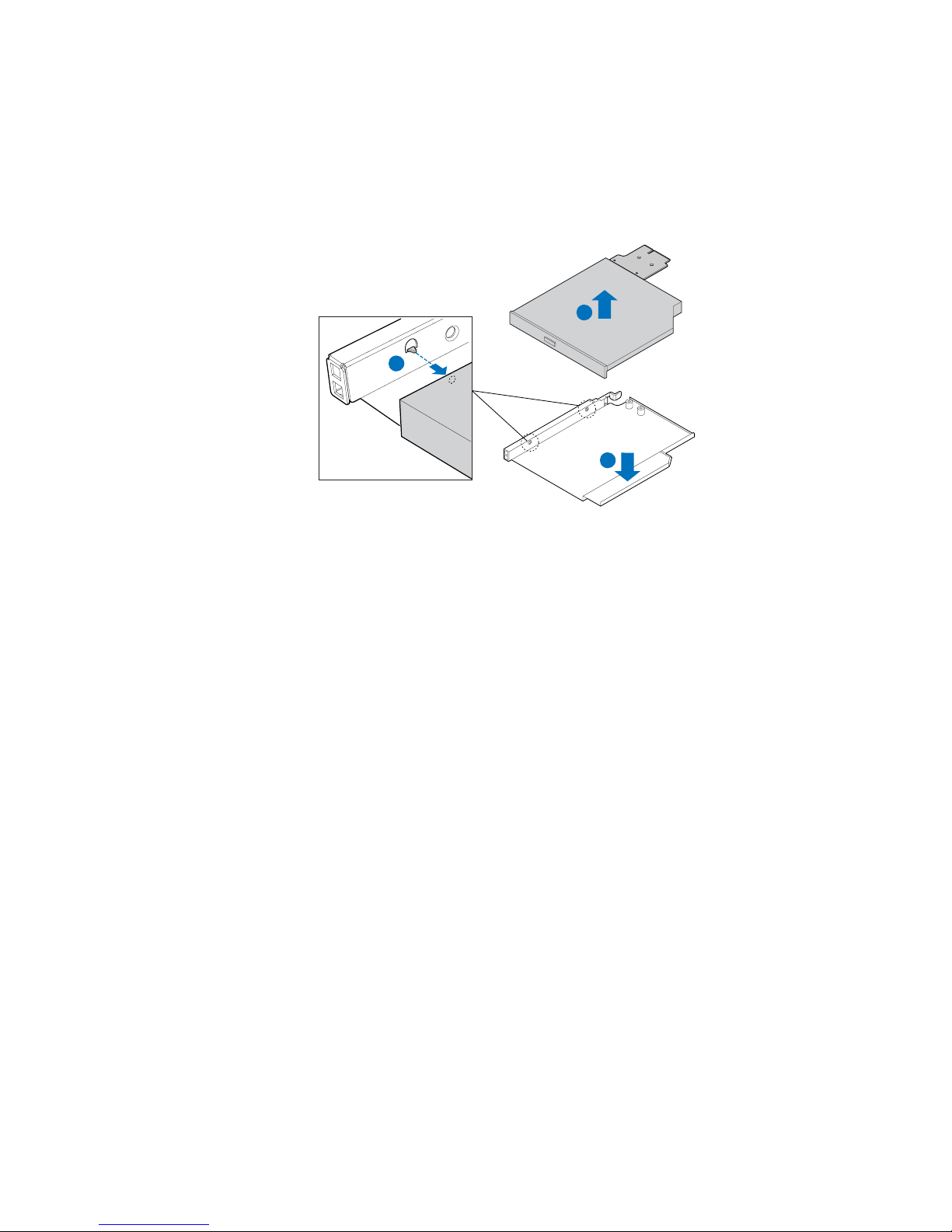
2. Press downward on the side of the tray (see letter “A”) and disengage the drive
from the two metal tabs on the opposite side of the tray.
3. Slide the optical drive out (see letter “B”) and lift up (see letter “C”) to remove it
from the tray.
C
B
A
AF000152
Figure 39. Removing the Slimline Optical Drive from the Tray
Filling Empty Server System Bays
A filler panel or drive blank must be installed into an empty drive bay. To access the drive
bays, remove the front bezel if it is installed. For instructions, see “Removing the Front
Bezel”. With the bezel removed, install the appropriate panel(s), blank, or empty hard
drive bay(s) as described below.
• If you do not have an optical drive installed in the slimline bay, install the slimline
filler panel.
• Install populated hard drive carriers into any remaining empty hard drive bays.
Installing and Removing the PCI Riser Assembly
Removing the PCI Riser Assembly
1. Disconnect any cables attached to any add-in cards.
2. Grasp the riser assembly and pull up to release it from the system.
38 Intel® Server System SR1560SF Service Guide
Page 61

Figure 40. Removing PCI Riser Assembly from the Server System
Installing the PCI Riser Assembly
1. Lower the riser assembly into place (see letter “A”).
2. Align the two hooks in the riser assembly with the matching slots at the back of the
server system (see letter “B”).
AF002354
Figure 41. Installing PCI Riser Assembly into the Server System
3. Press down uniformly until the two hooks on the rear of the PCI riser assembly
engage the server system back panel slots. The riser card will seat into the matching
socket on the server board. Ensure that the riser card is fully seated.
Intel® Server System SR1560SF Service Guide 39
A
B
AF002355
Page 62

4. Connect any cables to add-in cards that require them. See your add-in card
documentation for information and add-in card requirements.
Installing and Removing a PCI Add-in Card
The instructions below describe how to install and remove a PCI add-in card.
Installing a PCI Add-in Card
1. Remove the filler panel from the add-in card slot.
2. Insert add-in card until it seats in riser card connector (see letter “A”).
3. Screw the add-in card in place (see letter “B”).
B
Figure 42. Installing a Full Height Add-In Card
Note: Make sure that all empty add-in card slots have filler panels installed.
Removing a PCI Add-in Card
1. Remove the screw holding the add-in card in place (see letter “A”).
2. Remove the PCI add-in card from the riser card connector (see letter “B”).
A
A
AF002367
B
Note: Make sure that all empty add-in card slots have filler panels installed.
40 Intel® Server System SR1560SF Service Guide
AF002368
Figure 43. Removing a Full Height Add-In Card
Page 63

Installing and Removing the I/O Expansion
Module(s)
Installing the I/O Expansion Module(s)
1. Squeeze the sides of the I/O expansion module cover to disengage it from the server
system back panel and remove it (see letter “A”).
2. Attach the standoffs to the server board (see letter “B”) and attach the I/O
expansion module(s) to the server board (see letter “C”).
I/O Expansion
Module
(Dual Gigabit)
I/O Expansion
Module
(External SAS)
B
C
A
AF002376
Figure 44. Installing the I/O Expansion Module to the Server Board
Removing the I/O Expansion Module(s)
1. Remove the I/O expansion module(s) from the server board (see letter “A”).
2. Remove the standoffs from the server board (see letter “B”).
3. Install the I/O expansion module cover into the system back panel (see letter “C”).
I/O Expansion
Module
(Dual Gigabit)
I/O Expansion
Module
(External SAS)
B
A
Figure 45. Removing the I/O Expansion Module(s) from the Server Board
C
AF002377
Intel® Server System SR1560SF Service Guide 41
Page 64

Installing and Removing the Intel® Remote
Management Module 2 and the Intel
Installing the Intel® RMM2 and Intel® RMM2 NIC
1. Squeeze the sides of the Intel® RMM2 NIC module cover to disengage it from the
server system back panel and remove it.
2. Attach the foam gasket to the bottom of the Intel
“A”).
®
®
RMM 2 NIC
RMM2 NIC module (see letter
Note: The Intel
order to provide better detail on installing the foam gasket.
3. Attach the standoffs to the server board (see letter “B” in the figure below) and
attach the Intel
4. Insert the standoff into the hole labeled TH4 on the Intel
“D” in the figure below). The standoff installs on the bottom side of the Intel
RMM2 board.
5. Attach the Intel
into the matching hole on the server board (see letter “E” in the figure below).
®
RMM2 NIC module is shown upside down in the first illustration below in
®
RMM2 NIC module to the server board (see letter “C”).
®
RMM2 board (see letter
®
RMM2 board to the server board connector and snap the standoff
A
C
D
E
B
AF002378
®
Figure 46. Installing the Intel
42 Intel® Server System SR1560SF Service Guide
®
RMM2 and the Intel® RMM2 NIC Module to the
Server System
Page 65

Removing the Intel® RMM2 and Intel® RMM2 NIC
1. Remove the Intel® RMM2 board (see letter “A”) and standoffs (see letter “B”)
from the server board .
2. Remove the Intel
“D”) from the server board.
3. Install the Intel
®
RMM2 NIC module (see letter “C”) and standoffs (see letter
®
RMM2 NIC module cover into the system back panel.
A
C
B
D
AF002379
Figure 47. Removing the Intel
®
RMM and the Intel® RMM NIC Module from
the Server System
Installing/Replacing the Backplane Board (Hotswap Drive System Only)
The instructions below describe how to install and replace the backplane board.
Installing the Backplane Board
1. Lower the backplane board into the system (see letter “A”) and position the
backplane board over the retention pins as shown.
2. Slide the backplane board to the left (see letter “B”) to lock it in place and tighten
the captive screw (see letter “C”).
3. Connect power to the backplane power connector (see letter “D”).
Intel® Server System SR1560SF Service Guide 43
Page 66

D
B
A
C
AF002348
Figure 48. Installing the Backplane into the Server System
4. Connect fan, USB, and front panel cables as necessary to the backplane board.
5. Install the bridge board by opening the retention mechanism (see letter “A”) and
inserting it into the connector on the server board (see letter “B”). Close the
retention mechanism to hold the bridge board in place.
B
Figure 49. Installing the Bridge Board into the Server System
44 Intel® Server System SR1560SF Service Guide
A
C
A
C
AF000372
Page 67

Removing the Backplane Board
1. Disengage hard drives from the backplane board.
1. Disconnect all cables from the backplane board.
2. Remove the bridge board by lifting the retention mechanism from the backplane
and the server board (see letter “A”), and lifting straight up (see letter “B”).
A
Figure 50. Removing the Bridge Board from the Server System
..
B
B
A
AF000373
3. Disconnect the power from the backplane board (see letter “A”).
4. Loosen the captive screw on the backplane board (see letter “B”).
5. Hold the backplane board only by the edges. Slide the backplane board to the right
to release it and lift it over the retention pins (see letter “C”).
6. Lift the backplane board out of the server system (see letter “D”).
A
C
D
B
AF002349
Intel® Server System SR1560SF Service Guide 45
Page 68

Figure 51. Removing the Backplane from the Server System
7. Install a replacement backplane. For instructions, see “Installing the Backplane
Board”.
8. Install the bridge board (see Figure 49).
Replacing the Fan Board (Fixed Drive System
Only)
The instructions below describe how to replace the fan board.
Removing the Fan Board
1. Disconnect all fan cables from the fan board.
2. Disconnect the power from the fan board (see letter “A”).
3. Remove the screw from the fan board (see letter “B”).
4. Hold the fan board only by the edges. Slide the fan board to the right to release it
and lift it over the retention pins (see letter “C”).
5. Lift the fan board out of the server system (see letter “D”).
A
B
C
Figure 52. Removing the Fan Board from the Server System
6. Install a replacement fan board. For instructions, see “Installing the Fan Board”.
D
AF002351
46 Intel® Server System SR1560SF Service Guide
Page 69

Installing the Fan Board
1. Lower the fan board into the system (see let ter “A”) and position the fan board over
the retention pins as shown.
2. Slide the fan board to the left (see letter “B”) to lock it in place and install the screw
(see letter “C”).
3. Connect power to the fan board power connector (see letter “D”).
D
C
B
Figure 53. Installing the Fan Board into the Server System
4. Connect fan cables to the fan board.
Replacing the Server Board
Removing the Server Board
1. Remove CPU air duct and blue air baffle.
A
AF002350
2. If installed, remove memory, processor heat sinks, and processors from the server
board.
3. If installed, remove bridge board (hot-swap systems only).
4. If installed, remove the PCI riser assembly.
5. If installed, disconnect all SATA cables from the server board.
Intel® Server System SR1560SF Service Guide 47
Page 70

6. Remove the system fan assembly.
7. Disconnect all power cables coming from the power supply to the server board.
8. Remove the seven screws from the server board (see letter “A”) and lift the server
board from the server system (see letter “B”).
A
B
AF002346
Figure 54. Removing the Server Board
9. Install the replacement server board. For instructions, see “Installing the Server
Board”.
48 Intel® Server System SR1560SF Service Guide
Page 71

Installing the Server Board
1. Place the server board into the server system as shown in the figure below (see
letter “A”).
2. Attach the server board with seven screws (see letter “B”).
B
A
AF002347
Figure 55. Installing the Server Board
3. Re-connect all power cables coming from the power supply to the server board.
4. Install the system fan assembly.
5. Re-connect all SATA cables to the server board.
6. Install the PCI riser assembly.
7. Install the bridge board (hot-swap systems only).
8. Install memory, processor heat sinks, and processors.
9. Install the CPU air duct and blue air baffle.
Intel® Server System SR1560SF Service Guide 49
Page 72

Replacing the Backup Battery
The lithium battery on the server board powers the RTC for up to 10 years in the absence
of power. When the battery start s to weaken, it loses voltage, and the server settings stored
in CMOS RAM in the RTC (for example, the date and time) may be wrong . Contact your
customer service representative or dealer for a list of approved devices.
Warning: Danger of explosion if battery is incorrectly replaced. Replace only with the same or
equivalent type recommended by the equipment manufacturer. Discard used batteries
according to manufacturer's instructions.
Advarsel: Lithiumbatteri - Eksplosionsfare ved fejlagtig håndtering. Udskiftning må kun ske med
batteri af samme fabrikat og type. Levér det brugte batteri tilbage til leverandøren.
Advarsel: Lithiumbatteri - Eksplosjonsfare. Ved utskifting benyttes kun batteri som anbefalt av
apparatfabrikanten. Brukt batteri returneres apparatleverandøren.
Varning: Explosionsfara vid felaktigt batteribyte. Använd samma batterityp eller en ekvivalent typ
som rekommenderas av apparattillverkaren. Kassera använt batteri enligt fabrikantens
instruktion.
Varoitus: Paristo voi räjähtää, jos se on virheellisesti asennettu. Vaihda paristo ainoastaan
laitevalmistajan suosittelemaan tyyppiin. Hävitä käytetty paristo valmistajan ohjeiden
mukaisesti.
50 Intel® Server System SR1560SF Service Guide
Page 73

1. Locate the battery and insert the tip of a small flat bladed screwdriver, or an
equivalent, under the tab in the plastic retainer. Gently push down on the
screwdriver to lift the battery.
2. Remove the battery from its socket.
AF002375
Figure 56. Replacing the Backup Battery
3. Dispose of the battery according to local ordinance.
4. Remove the new lithium battery from its package, and, being careful to observe the
correct polarity, insert it in the battery socket.
Note: You will need to run BIOS Setup to restore the system configuration settings to the RTC.
Replacing the Power Supply
Caution: The power supply is not hot-swappable. Before removing or replacing the power supply,
you must first take the server out of service, turn off all peripheral devices connected to
the system, turn off the system by pressing the power button, and unplug the AC power
cord from the system or wall outlet.
Intel® Server System SR1560SF Service Guide 51
Page 74

The power supply can be replaced if it fails or if one of the fans that is integrated into it
fails. To replace the power supply, use the following instructions.
1. Disconnect all power cables.
2. Lift the power supply to disengage it from the latch (see letter “A”) and remove the
power supply by sliding it out (see letter “B”).
B
A
supply, re-connect all power cables
in step 1 above, and reconnect AC power cord.
Figure 57. Removing Power Supply from the Server System
3. Insert the replacement power supply module (see letter “A”) until it clicks into
place behind the latch (see letter “B”). Reconnect all power cables.
AF002358
A
B
supply, re-connect all power cables
in step 1 above, and reconnect AC power cord.
Figure 58. Installing Power Supply into the Server System
AF002359
Replacing the Control Panel Module (Hot-swap
Drive System)
Your server must be operated with a control panel installed.
Caution: The control panel is NOT hot-swappable. Before removing or replacing the contr ol panel,
you must first take the server out of service, turn off all peripheral devices connected to
the system, turn off the system by pressing the power button, and unplug the AC power
cord from the system or wall outlet.
52 Intel® Server System SR1560SF Service Guide
Page 75

1. Unplug the front panel and USB cables from the backplane (see letters “A” and
“B”).
2. Press the latch at the back of the control panel (see letter “C”).
3. Slide the control panel out through the front of the server system (see letter “D”).
A
C
D
B
AF002342
Figure 59. Removing the Control Panel Module (Hot-swap Drive System)
4. Slide the replacement control panel into the server system (see letter “A”) until it
clicks into place.
5. Connect the USB and front panel cables to the connectors on the backplane (see
letters “B” and “C”).
C
B
Figure 60. Installing Control Panel Module into the Server System (Hot-swap
Intel® Server System SR1560SF Service Guide 53
A
AF002343
Drive System)
Page 76
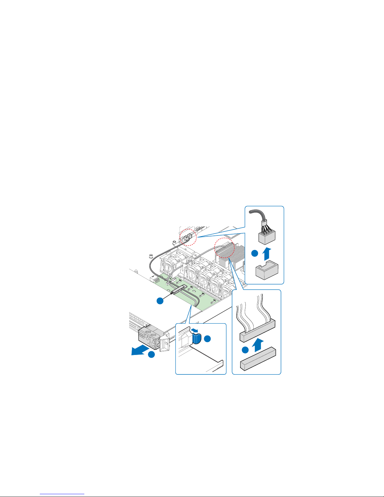
Replacing the Control Panel Module (Fixed Drive
System)
Your server must be operated with a control panel installed.
Caution: The control panel is NOT hot-swappable. Before removing or replacing the contr ol panel,
you must first take the server out of service, turn off all peripheral devices connected to
the system, turn off the system by pressing the power button, and unplug the AC power
cord from the system or wall outlet.
1. Unplug the USB cable from the server board (see letter “A”).
2. Unplug the front panel cable from the server board (see letter “B”).
3. Remove the cables from the retaining clip on the fan board (see letter “C”).
4. Press the latch at the back of the control panel (see letter “D”).
5. Slide the control panel out through the front of the server system (see letter “E”).
A
C
D
E
B
AF002344
Figure 61. Removing the Control Panel Module (Fixed Drive System)
54 Intel® Server System SR1560SF Service Guide
Page 77

6. Slide the replacement control panel into the server system (see letter “A”) until it
clicks into place.
7. Route the USB and front panel cables through the retaining clip on the fan board
(see letter “B”).
8. Connect the front panel cable to the connector on the server board (see letter “C”).
9. Connect the USB cable to the connector on the server board (see letter “D”).
D
B
A
C
AF002345
Figure 62. Installing Control Panel Module into the Server System (Fixed
Drive System)
Replacing a System Fan
Caution: The system fans operate at extr emely fast speeds; the fans ar e NOT hot-swappable. Befor e
removing or replacing a fan, you must first take the server out of service, turn off all
peripheral devices connected to the system, turn off the system by pressing the power
button, and unplug the AC power cord from the system or wall outlet.
Note: The fans that are integrated into the power supply cannot be r eplaced separately. If one of
the fans in the power supply fails, the power supply must be replaced.
®
The system fans at the front of the Intel
replaced if one of them fails. Use the steps below to replace a fan.
Server System SR1560SF can be individually
Intel® Server System SR1560SF Service Guide 55
Page 78

1. Disconnect the fan cable from the backplane or fan board (see letter “A”). Lift the
failed fan from the module (see letter “B”).
A
B
AF002356
Figure 63. Removing a Fan from the Fan Module
2. Position the replacement fan so the connector on the fan is at t he right and pointing
down.
3. With the fan oriented correctly, insert the fan into the fan module (see letter “A”),
and insert the fan cable into the matching connector on the backplane or fan board
(see letter “B”).
B
A
AF002357
Figure 64. Installing a Fan into the Fan Module
56 Intel® Server System SR1560SF Service Guide
Page 79

Installing and Removing the Rack Handles
Installing the Rack Handles
Align the rack handle with the two holes on the side of the server system and attach the
rack handle with the two screws.
AF000377
Figure 65. Installing the Rack Handle
Removing the Rack Handles
Remove the two screws holding the rack handle in place, and remove the rack handle from
the server system.
Intel® Server System SR1560SF Service Guide 57
AF000378
Figure 66. Removing the Rack Handle
Page 80

58 Intel® Server System SR1560SF Service Guide
Page 81

4 Server Utilities
Using the BIOS Setup Utility
This section describes the BIOS Setup Utility options, which is used to change server
configuration defaults. You can run BIOS Setup with or without an operating system
being present. See “Server System References” for a link to the Intel
S5400SF T echnical Product Specification where you will find details about specific BIOS
setup screens.
Starting Setup
You can enter and start BIOS Setup under several conditions:
• When you turn on the server, after POST completes the memory test.
• When you have moved the CMOS jumper on the server board to the "Clear CMOS"
position (enabled).
In the two conditions listed above, during the Power On Self Test (POST), you will see
this prompt:
Press <F2> to enter SETUP
®
Server Board
In a third condition, when CMOS/NVRAM has been corrupted, you will see other
prompts but not the <F2> prompt:
Warning: CMOS checksum invalid
Warning: CMOS time and date not set
In this condition, the BIOS will load default values for CMOS and attempt to boot.
If You Cannot Access Setup
If you are not able to access BIOS Setup, you might need to clear the CMOS memory. For
instructions on clearing the CMOS, see "Clearing the CMOS".
Setup Menus
Each BIOS Setup menu page contains a number of features. Except for those features that
are provided only to display automatically configured information, each feature is
associated with a value field that contains user-selectable parameters. These parameters
can be changed if the user has adequate security rights. If a value cannot be changed for
any reason, the feature's value field is inaccessible.
Page 82

“Setup Menu Key Use” describes the keyboard commands you can use in the BIOS Setup
menus.
Table 4. Setup Menu Key Use
Key to Press Description
<F1> Pressing <F1> on any menu invokes the general help window.
Left and right arrows The left and right arrow keys are used to move between the major menu
pages. The keys have no affect if a submenu or pick list is displayed.
Up arrow Select Item up - The up arrow is used to select the previous value in a
menu item's option list, or a value field pick list. Pressing the <Enter> key
activates the selected item.
Down arrow Select Item down - The down arrow is used to select the next value in a
menu item's option list, or a value field pick list. Pressing the <Enter> key
activates the selected item.
<F5> or <-> Change Value - The minus key or the <F5> function key is used to
change the value of the current item to the previous value. This key
scrolls through the values in the associated pick list without displaying
the full list.
<F6> or <+> Change Value - The plus key or the <F6> function key is used to change
the value of the current menu item to the next value. This key scrolls
through the values in the associated pick list without displaying the full
list. On 106-key Japanese keyboards, the plus key has a different scan
code than the plus key on the other keyboard, but it has the same effect.
<Enter> Execute Command - The <Enter> key is used to activate submenus
when the selected feature is a submenu, or to display a pick list if a
selected feature has a value field, or to select a sub-field for multi-valued
features like time and date. If a pick list is displayed, the <Enter> key will
undo the pick list, and allow another selection in the parent menu.
<Esc> Exit - The <Esc> key provides a mechanism for backing out of any field.
<F9> Setup Defaults - Pressing <F9> causes the following to appear:
This key will undo the pressing of the <Enter> key. When the <Esc> key
is pressed while editing any field or selecting features of a menu, the
parent menu is re-entered. When the <Esc> key is pressed in any
submenu, the parent menu is re-entered. When the <Esc> key is
pressed in any major menu, the exit confirmation window is displayed
and the user is asked whether changes can be discarded.
Setup Confirmation
Load default configuration now?
[Yes] [No]
If "Yes" is selected and the <Enter> key is pressed, all Setup fields are
set to their default values. If "No" is selected and the <Enter> key is
pressed, or if the <Esc> key is pressed, the user is returned to where
they were before <F9> was pressed without affecting any existing field
values.
60 Intel® Server System SR1560SF Service Guide
Page 83

Key to Press Description
<F10> Save and Exit - Pressing <F10> causes the following message to
appear:
If "Yes" is selected and the <Enter> key is pressed, all changes are
saved and Setup is exited. If "No" is selected and the <Enter> key is
pressed, or the <Esc> key is pressed, the user is returned to where they
were before <F10> was pressed without affecting any existing values.
Upgrading the BIOS
The upgrade utility allows you to upgrade the BIOS in flash memory. The code and data in
the upgrade file include the following:
• On-board system BIOS, including the recovery code, BIOS Setup Utility, and
strings.
• On-board video BIOS, and other option ROMs for devices embedded on the server
board.
Table 4. Setup Menu Key Use
Setup Confirmation
Save Configuration changes and exit now?
[Yes] [No]
• OEM binary area
• Microcode
• A way to change the BIOS language
Preparing for the Upgrade
The steps below explain how to prepare to upgrade the BIOS, including how to record th e
current BIOS settings and how to obtain the upgrade utility.
Recording the Current BIOS Settings
1. Boot the computer and press <F2> when you see the message:
Press <F2> Key if you want to run SETUP
2. Write down the current settings in the BIOS Setup program.
Note: Do not skip step 2. You will need these settings to configure your server at the end of the
procedure.
Intel® Server System SR1560SF Service Guide 61
Page 84

Obtaining the Upgrade
Download the BIOS image file to a temporary folder on your hard drive. See “Server
System References” for a link to the update software.
Note: Review the instructions and release notes that are provided in the readme file distributed
with the BIOS image file before attempting a BIOS upgrade. The release notes contain
critical information regarding jumper settings, specific fixes, or other information to
complete the upgrade.
Upgrading the BIOS
Follow the instructions in the readme file that came with the BIOS upgrade. When the
update completes, remove the bootable media from which you performed the upgrade.
Caution: Do not power down the system during the BIOS update pr ocess! Doing so may corrupt the
system BIOS.
Note: You may encounter a CMOS Checksum error or other problem after reboot. If this
happens, shut down the system and boot it again. CMOS checksum err ors r equir e that you
enter Setup, check your settings, save your settings, and exit Setup.
Clearing the CMOS
If you are not able to access the BIOS setup screens, the CMOS Clear jumper will need to
be used to reset the configuration RAM.
1. Power down the system; do not disconnect the AC power.
2. Open the server.
3. Move the jumper from the normal operation position, CMOS Protect at pins 1 and
2, to the CMOS Clear Force Erase position, covering pins 2 and 3.
Password
Reset
BMC Force
Update Mode
Disable
2
2
3
2
CMOS
Clear
3
Enable
3
Figure 67. Clear CMOS Jumper
AF002170
62 Intel® Server System SR1560SF Service Guide
Page 85

4. Wait five seconds.
5. Return the CMOS Clear jumper to the CMOS Protect location, covering pin s 1 and
2.
6. Close the server chassis.
7. Power up the system.
8. The CMOS is now cleared and can be reset by going into the BIOS setup.
Resetting the Password
If the user or administrator password(s) is lost or forgotten, moving the password reset
jumper into the "clear" position clears both passwords. The password reset jumper must
be restored to its original position before a new password(s) can be set.
1. Power down the system; do not disconnect the AC power.
2. Open the server system.
3. Move the jumper from the normal operation position, Password Clear Protect, at
pins 1 and 2 to the Password Clear Erase position, covering pins 2 and 3.
BMC Force
Update Mode
Disable
Enable
AF002170
Password
Reset
2
2
3
3
2
3
CMOS
Clear
Figure 68. Password Reset Jumper
4. Wait five seconds.
5. Return the Password Reset jumper to the Password Clear Protect position, covering
pins 1 and 2.
6. Close the server system.
7. Power up the server.
8. The password is now cleared and can be reset by going into BIOS setup.
Intel® Server System SR1560SF Service Guide 63
Page 86

64 Intel® Server System SR1560SF Service Guide
Page 87

Appendix A: Technical Reference
600W Single Power Supply Input Voltages
• 100-127V at 50/60 Hz; 8.55 A max.
• 200-240V at 50/60 Hz; 4.3 A max.
System Environmental Specifications
Table 5. System Environmental Specifications
Temperature
Non-operating
Operating
-40 ° to +70 °C.
10° C to 35° C (50° F to 90° F) with the maximum rate of change not to
exceed 10° C per hour
Humidity
Non-operating 90% relative humidity (non-condensing) at 28 °C.
Shock
Operating
Unpackaged
Packaged
Acoustic noise Sound Pressure: 55 dBA (rack mount) in an idle state at typical office
Electrostatic
discharge (ESD)
2.0 g, 11 msec, 1/2 sine
Trapezoidal, 25 g, velocity change 136 inches/sec (40 lbs to > 80 lbs)
Non-palletized free fall at a height of 24 inches (40 lbs to > 80 lbs)
ambient temperature. (23 +/- degrees C) Sound Power: 7.0 BA in an idle
state at typical office ambient temperature. (23 +/- 2 degrees C).
+/-15kV except I/O port +/-8KV, per Intel Environmental Test Specification.
Page 88

66 Intel® Server System SR1560SF Service Guide
Page 89

Appendix B: Intel® Server Issue Report
Form
Note: An on-line / automatic submission version of this form is available at http://
support.intel.com/support/motherboards/server/s5400sf/. For the fastest service, please
submit your form via the Internet.
Date Submitted: _______________________________________________________
Company Name: ________________________________ __ ____________________
Contact Name: ________________________________________________________
Email Address: _______________________________________________________
Intel Server Product: ___________________________________________________
Priority (Critical, Hot, High, Low): _______________________________________
Brief Problem Description. Provide a brief description below. See the last page for space
to include a detailed problem description.
____________________________________________________________________
____________________________________________________________________
____________________________________________________________________
____________________________________________________________________
____________________________________________________________________
Board / Chassis Information
Baseboard Revision - PBA#: _____________________________________________
Baseboard Serial Number: _______________________________________________
Chassis Model:________________________________________________________
CPU1 Speed/Stepping/Spec: _____________________________________________
CPU2 Speed/Stepping/Spec: _____________________________________________
System BIOS Version: __________________________________________________
HSC Firmware Version:_____________________________ ___ _________________
Page 90

DIMM Configuration
DIMM A1 MB and Vendor / part number:__________________________________
DIMM A2 MB and Vendor / part number:__________________________________
DIMM A3 MB and Vendor / part number:__________________________________
DIMM A4 MB and Vendor / part number:__________________________________
DIMM B1 MB and Vendor / part number: __________________________________
DIMM B2 MB and Vendor / part number: __________________________________
DIMM B3 MB and Vendor / part number: __________________________________
DIMM B4 MB and Vendor / part number: __________________________________
DIMM C1 MB and Vendor / part number: __________________________________
DIMM C2 MB and Vendor / part number: __________________________________
DIMM C3 MB and Vendor / part number: __________________________________
DIMM C4 MB and Vendor / part number: __________________________________
DIMM D1 MB and Vendor / part number:__________________________________
DIMM D2 MB and Vendor / part number:__________________________________
DIMM D3 MB and Vendor / part number:__________________________________
DIMM D4 MB and Vendor / part number:__________________________________
Operating System Information
Operating System:_____________________________________________________
Version: _____________________________________________________________
Service Pack:_________________________________________________________
68 Intel® Server System SR1560SF Service Guide
Page 91

Add-in Card, Peripheral, Video, NIC
Check each box below as applicable, and provide the requested information.
Peripheral Card or Peripheral Description Driver Revision IRQ # I/O Base Address NIC
Peripheral Description
PCIe* Gen2
Riser Card Slot
Video
On-board Video
Add-in Video
NIC
On-Board NIC1
On-Board NIC2
Hard Drive Information
Drive Type (SATA/
SAS)
Make/Model
Driver
Revision
Hot-swap
or Fixed
IRQ
IRQ
I/O Base
Address
FW
Revision
FW
Revision
Management Information
On-Board Platform Instrumentation only ___________________________________
®
Remote Management Module_______________________________________
Intel
Intel® Server System SR1560SF Service Guide 69
Page 92

Complete Problem Description
In the space below, provide a complete description of the steps used to reproduce the
problem or a complete description of where the problem can be found. Please also include
any details on troubleshooting already done.
____________________________________________________________________
____________________________________________________________________
____________________________________________________________________
____________________________________________________________________
____________________________________________________________________
____________________________________________________________________
____________________________________________________________________
____________________________________________________________________
____________________________________________________________________
____________________________________________________________________
____________________________________________________________________
____________________________________________________________________
____________________________________________________________________
____________________________________________________________________
____________________________________________________________________
____________________________________________________________________
____________________________________________________________________
____________________________________________________________________
____________________________________________________________________
____________________________________________________________________
____________________________________________________________________
70 Intel® Server System SR1560SF Service Guide
Page 93

Appendix C: LED Decoder
During the system boot process, BIOS executes a number of platform configuration
processes, each of which is assigned a specific hex POST code number. As each
configuration routine is started, BIOS will display the given POST code to the POST
Code Diagnostic LEDs found on the back edge of the server board. To assist in
troubleshooting a system hang during the POST process, the Diagnostic LEDs can be used
to identify the last POST process to be executed.
Each POST code will be represented by a combination of colors from the four LEDs. The
LEDs are capable of displaying three colors: green, red, and amber. The POST codes are
divided into two nibbles, an upper nibble and a lower nibble. Each bit in the upper nibble
is represented by a red LED and each bit in the lower nibble is represented by a green
LED. If both bits are set in the upper and lower nibbles then both red and green LEDs are
lit, resulting in an amber color. If both bits are clear, then the LED is off.
In the below example, BIOS sends a value of ACh to the diagnostic LED decoder. The
LEDs are decoded as follows:
• red bits = 1010b = Ah
• green bits = 1100b = Ch
Since the red bits correspond to the upper nibble and the green bits correspond to the
lower nibble, the two are concatenated to be ACh.
Table 6. POST Progress Code LED Example
8h 4h 2h 1h
LEDs Red Green Red Green Red Green Red Green
ACh11011 0 0 0
Result Amber Green Red Off
MSB LSB
AF002177
Figure 69. Diagnostic LED Placement Diagram
Page 94
Table 7. Diagnostic LED POST Code Decoder
Checkpoint Diagnostic LED Decoder Description
G=Green, R=Red, A=Amber
MSB LSB
Host Processor
0x10h OFF OFF OFF R Power-on initialization of the host processor
0x11h OFF OFF OFF A Host processor cache initialization (including AP)
0x12h OFF OFF G R Starting application processor initialization
0x13h OFF OFF G A SMM initialization
Chipset
0x21h OFF OFF R G Initializing a chipset component
Memory
0x22h OFF OFF A OFF Reading configuration data from memory (SPD
0x23h OFF OFF A G Detecting presence of memory
0x24h OFF G R OFF Programming timing parameters in the memory
0x25h OFF G R G Configuring memory parameters in the memory
0x26h OFF G A OFF Optimizing memory controller settings
0x27h OFF G A G Initializing memory, such as ECC init
0x28h G OFF R OFF Testing memory
(bootstrap processor)
on DIMM)
controller
controller
72 Intel® Server System SR1560SF Service Guide
Page 95

Table 7. Diagnostic LED POST Code Decoder
PCI Bus
0x50h OFF R OFF R Enumerating PCI busses
0x51h OFF R OFF A Allocating resources to PCI busses
0x52h OFF R G R Hot Plug PCI controller initialization
0x53h OFF R G A Reserved for PCI bus
0x54h OFF A OFF R Reserved for PCI bus
0x55h OFF A OFF A Reserved for PCI bus
0x56h OFF A G R Reserved for PCI bus
0x57h OFF A G A Reserved for PCI bus
USB
0x58h G R OFF R Resetting USB bus
0x59h G R OFF A Reserved for USB devices
ATA / ATAPI / SATA
0x5Ah G R G R Resetting PATA / SATA bus and all devices
0x5Bh G R G A Reserved for ATA
SMBUS
0x5Ch G A OFF R Resetting SMBUS
0x5Dh G A OFF A Reserved for SMBUS
Local Console
0x70h OFFRRRResetting the video controller (VGA)
0x71h OFF R R A Disabling the video controller (VGA)
0x72h OFF R A R Enabling the video controller (VGA)
Remote Console
0x78h G RRRResetting the console controller
0x79h G R R A Disabling the console controller
0x7Ah G R A R Enabling the console controller
Keyboard (PS2 or USB)
0x90h R OFF OFF R Resetting the keyboard
0x91h R OFF OFF A Disabling the keyboard
0x92h R OFF G R Detecting the presence of the keyboard
0x93h R OFF G A Enabling the keyboard
Intel® Server System SR1560SF Service Guide 73
Page 96

Table 7. Diagnostic LED POST Code Decoder
0x94h R G OFF R Clearing keyboard input buffer
0x95h R G OFF A Instructing keyboard controller to run Self Test
(PS2 only)
Mouse (PS2 or USB)
0x98h A OFF OFF R Resetting the mouse
0x99h A OFF OFF A Detecting the mouse
0x9Ah A OFF G R Detecting the presence of mouse
0x9Bh A OFF G A Enabling the mouse
Fixed Media
0xB0h R OFF R R Resetting fixed media device
0xB1h R OFF R A Disabling fixed media device
0xB2h R OFF A R Detecting presence of a fixed media device (IDE
hard drive detection, etc.)
0xB3h R OFF A A Enabling / configuring a fixed media device
Removable Media
0xB8h A OFF R R Resetting removable media device
0xB9h A OFF R A Disabling removable media device
0xBAh A OFF A R Detecting presence of a removable media device
(IDE CDROM detection, etc.)
0xBCh A G R R Enabling / configuring a removable media device
Boot Device Selection
0xD0 R R OFF R Trying boot device selection
0xD1 R R OFF A Trying boot device selection
0xD2 R R G R Trying boot device selection
0xD3 R R G A Trying boot device selection
0xD4 R A OFF R Trying boot device selection
0xD5 R A OFF A Trying boot device selection
0xD6 R A G R Trying boot device selection
0xD7 R A G A Trying boot device selection
0xD8 A R OFF R Trying boot device selection
0xD9 A R OFF A Trying boot device selection
0XDA A R G R Trying boot device selection
0xDB A R G A Trying boot device selection
74 Intel® Server System SR1560SF Service Guide
Page 97

Table 7. Diagnostic LED POST Code Decoder
0xDC A A OFF R Trying boot device selection
0xDE A A G R Trying boot device selection
0xDF A A G A Trying boot device selection
Pre-EFI Initialization (PEI) Core
0xE0h R R R OFF Started dispatching early initialization modules
(PEIM)
0xE2h R R A OFF Initial memory found, configured, and installed
0xE1h R R R G Reserved for initialization module use (PEIM)
0xE3h R R A G Reserved for initialization module use (PEIM)
Driver Execution Environment (DXE) Core
0xE4h R A R OFF Entered EFI driver execution phase (DXE)
0xE5h R A R G Started dispatching drivers
0xE6h R A A OFF Started connecting drivers
DXE Drivers
0xE7h R A A G Waiting for user input
0xE8h A R R OFF Checking password
0xE9h A R R G Entering BIOS setup
0xEAh A R A OFF Flash Update
0xEEh A A A OFF Calling Int 19. One beep unless silent boot is
0xEFh A A A G Unrecoverable boot failure / S3 resume failure
Runtime Phase / EFI Operating System Boot
correctly
enabled.
0xF4h R A R R Entering Sleep state
0xF5h R A R A Exiting Sleep state
0xF8h A RRROperating system has requested EFI to close
0xF9h A R R A Operating system has switched to virtual
0xFAh A R A R Operating system has requested the system to
Pre-EFI Initialization Module (PEIM) / Recovery
0x30h OFF OFF R R Crisis recovery has been initiated because of a
Intel® Server System SR1560SF Service Guide 75
boot services (ExitBootServices ( ) has been
called)
address mode (SetVirtualAddressMap ( ) has
been called)
reset (ResetSystem () has been called)
user request
Page 98

Table 7. Diagnostic LED POST Code Decoder
0x31h OFF OFF R A Crisis recovery has been initiated by software
(corrupt flash)
0x34h OFF G R R Loading crisis recovery capsule
0x35h OFF G R A Handing off control to the crisis recovery capsule
0x3Fh G G A A Unable to complete crisis recovery.
76 Intel® Server System SR1560SF Service Guide
Page 99

Appendix D: Getting Help
World Wide Web
http://support.intel.com/support/motherboards/server/s5400sf/.
Telephone
All calls are billed per incident, levied in local currency at the applicable credit card
exchange rate plus applicable taxes. (Intel reserves the right to change the pricing for
telephone support at any time without notice).
Before calling, fill out an “Intel
on the following pages. However, for the fastest service, please submit your form via the
Internet.
For an updated support contact list, see http://www.intel.com/support/9089.htm/
U.S. and Canada
916-377-7000
Europe
Belgium ..... 02 714 3182
Denmark ... 38 487077
Finland ...... 9 693 79297
France........ 01 41 918529
Germany ... 069 9509 6099
Holland...... 020 487 4562
Italy............ 02 696 33276
®
Server Issue Report Form”. A sample form is provided
Norway...... 23 1620 50
Spain..........91 377 8166
Sweden....... 08 445 1251
UK.............. 870 6072439
Page 100

In Asia-Pacific region
Australia.... 1800 649931
Cambodia.. 63 2 636 9797 (via Philippines)
China......... 800 820 1100 (toll-free)
.................... 8 621 33104691 (not toll-free)
Hong Kong 852 2 844 4456
India........... 0006517 2 68303634 (manual toll-free. You need an IDD-equipped
telephone)
Indonesia... 803 65 7249
Korea......... 822 767 2595
Malaysia.... 1 800 80 1390
Myanmar... 63 2 636 9796 (via Philippines)
New Zealand 0800 444 365
Pakistan..... 632 63684 15 (IDD via Philippines)
Philippines 1 800 1 651 0117
Singapore .. 65 6213-1311
Taiwan .......2 2545-1640
Thailand.... 1 800 631 0003
Vietnam ..... 632 6368416 (IDD via Philippines)
Japan
Domestic.... 0120 868686
Outside country 81 298 47 0800
Latin America
Argentina .. Contact AT&T USA at 0-800 222 1288. Once connected, dial 800 843 4481
Brazil......... 001-916 377 0180
Chile
Easter Island.. ............ Contact AT&T USA at 800 800 311. Once
connected, dial 800 843 4481
Mainland and Juan .. Contact AT&T USA at 800 225 288. Once
connected, dial 800 843 4481
78 Intel® Server System SR1560SF Service Guide
 Loading...