

Intel SR1530AH - Server System - 0 MB RAM, SR1530AHLX, SR1530HAHLX, SR1530 - AHJPCIERISER PCI-E x8 Riser Card User Manual
Page 1

Intel® Server System SR1530AH /
SR1530AHLX / SR1530HAHLX
User’s Guide
A Guide for Technically Qualified Assemblers of Intel® Identified Subassemblies/
Products
Intel Order Number D59196-002
Page 2

Disclaimer
Information in this document is provided in connection with Intel® products. No license, express or implied, by
estoppel or otherwise, to any intellectual property rights is granted by this document. Except as provided in Intel's
Terms and Conditions of Sale for such products, Intel assumes no liability whatsoever, and Intel disclaims any
express or implied warranty, relating to sale and/or use of Intel products including liability or warranties relating to
fitness for a particular purpose, merchantability, or infringement of any patent, copyright or other intellectual property
right. Intel products are not designed, intended or authorized for use in any medical, life saving, or life sustaining
applications or for any other application in which the failure of the Intel product could create a situation where
personal injury or death may occur. Intel may make changes to specifications and product descriptions at any time,
without notice.
Intel server boards contain a number of high-density VLSI and power delivery components that need adequate
airflow for cooling. Intel's own chassis are designed and tested to meet the intended thermal requirements of these
components when the fully integrated system is used together. It is the responsibility of the system integrator that
chooses not to use Intel developed server building blocks to consult vendor datasheets and operating parameters to
determine the amount of airflow required for their specific application and environmental conditions. Intel Corporation
can not be held responsible if components fail or the server board does not operate correctly when used outside any
of their published operating or non-operating limits.
Intel and Intel Xeon are trademarks or registered trademarks of Intel Corporation or its subsidiaries in the United
States and other countries.
* Other names and brands may be claimed as the property of others.
Copyright © 2006, Intel Corporation. All Rights Reserved
ii Intel® Server System SR1530AH / SR1530AHLX / SR1530HAHLX User’s Guide
Page 3

Safety Information
Important Safety Instructions
Read all caution and safety statements in this document before performing any of the
instructions. See also Intel Server Boards and Server Chassis Safety Information on the
®
Server Deployment Toolkit 2.0 CD and/or at http://support.intel.com/support/
Intel
motherboards/server/sb/cs-010770.htm.
Wichtige Sicherheitshinweise
Lesen Sie zunächst sämtliche Warnund Sicherheitshinweise in diesem Dokument, bevor
Sie eine der Anweisungen ausführen. Beachten Sie hierzu auch die Sicherheitshinweise zu
Intel-Serverplatinen und Servergehäusen auf der Intel
oder unter http://support.intel.com/support/motherboards/server/sb/cs-010770.htm.
®
Server Deployment T oolkit 2.0 CD
Consignes de sécurité
Lisez attention toutes les consignes de sécurité et les mises en garde indiquées dans ce
document avant de suivre toute instruction. Consultez Intel Server Boards and Server
Chassis Safety Information sur le Intel
rendez-vous sur le site http://support.intel.com/support/motherboards/server/sb/cs-
010770.htm.
®
Server Deployment Toolkit 2.0 CD ou bien
Instrucciones de seguridad importantes
Lea todas las declaraciones de seguridad y precaución de este documento antes de realizar
cualquiera de las instrucciones. Vea Intel Server Boards and Server Chassis Safety
Information en el Intel
support.intel.com/support/motherboards/server/sb/cs-010770.htm.
®
Server Deployment Toolkit 2.0 CD y/o en http://
Page 4

重要安全指导
在执行任何指令之前,请阅读本文档中的所有注意事项及安全声明。 和/或
http://support.intel.com/support/motherboards/server/sb/CS-010770.htm
上的 Intel
Server Boards and Server Chassis Safety Information(《Intel
服务器主板与服务器机箱安全信息》)。
iv Intel® Server System SR1530AH / SR1530AHLX / SR1530HAHLX User’s Guide
Page 5

Warnings
Heed safety instructions: Before working with your server product, whether you are
using this guide or any other resource as a reference, pay close attention to the safety
instructions. You must adhere to the assembly instructions in this guide to ensure and
maintain compliance with existing product certifications and approvals. Use only the
described, regulated components specified in this guide. Use of other products /
components will void the UL listing and other regulatory approvals of the product and
will most likely result in noncompliance with product regulations in the region(s) in which
the product is sold.
System power on/off: The power button DOES NOT turn off the system AC power. To
remove power from system, you must unplug the AC power cord from the wall outlet.
Make sure the AC power cord is unplugged before you open the chassis, add, or remove
any components.
Hazardous conditions, devices and cables: Hazardous electrical conditions may be
present on power, telephone, and communication cables. Turn off the server and
disconnect the power cord, telecommunications systems, networks, and modems attached
to the server before opening it. Otherwise, personal injury or equipment damage can
result.
Electrostatic discharge (ESD) and ESD protection: ESD can damage disk drives,
boards, and other parts. We recommend that you perform all procedures in this chapter
only at an ESD workstation. If one is not available, provide some ESD protection by
wearing an antistatic wrist strap attached to chassis ground any unpainted metal surface on
your server when handling parts.
ESD and handling boards: Always handle boards carefully. They can be extremely
sensitive to ESD. Hold boards only by their edges. After removing a board from its
protective wrapper or from the server, place the board component side up on a grounded,
static free surface. Use a conductive foam pad if available but not the board wrapper. Do
not slide board over any surface.
Installing or removing jumpers: A jumper is a small plastic encased conductor that slips
over two jumper pins. Some jumpers have a small tab on top that you can grip with your
fingertips or with a pair of fine needle nosed pliers. If your jumpers do not have such a tab,
take care when using needle nosed pliers to remove or install a jumper; grip the narrow
sides of the jumper with the pliers, never the wide sides. Gripping the wide sides can
damage the contacts inside the jumper, causing intermittent problems with the function
controlled by that jumper. Take care to grip with, but not squeeze, the pliers or other tool
you use to remove a jumper, or you may bend or break the pins on the board.
Intel® Server System SR1530AH / SR1530AHLX / SR1530HAHLX User’s Guide v
Page 6

vi Intel® Server System SR1530AH / SR1530AHLX / SR1530HAHLX User’s Guide
Page 7

Preface
About this Manual
Thank you for purchasing and using the Intel® Server System SR1530AH /
SR1530AHLX / SR1530HAHLX.
This manual is written for system technicians who are responsible for troubleshooting,
upgrading, and repairing this server system. This document provides reference
information, feature information, and step by step instructions on how to add and replace
components on the server system. For the latest version of this manual, see http://
support.intel.com/support/motherboards/server/S3000AH/.
Manual Organization
Chapter 1 provides an overview of the server system. In this chapter, you will find a list of
the server system features, illustrations of the product, and product diagrams to help you
identify components and their locations.
Chapter 2 provides instructions on using the utilities that are shipped with the board or
that may be required to update the system. This includes how to navigate through the
BIOS Setup screens, how to perform a BIOS update, and how to reset the password or
CMOS. Information about the specific BIOS settings and screens is available in the Intel
Server Board S3000AH Technical Product Specification. See Table 1 on page x for a link
to the Technical Product Specification.
Chapter 3 provides instructions on adding and replacing components. Use this chapte r for
step-by-step instructions and diagrams for installing or replacing components such as the
fans, power supply, drives, and other components.
At the back of this manual, you will find technical specifications, troubleshooting tips,
regulatory information, complete safety information, “getting help” information, and the
warranty.
®
Page 8

Product Contents
The Intel® Server System SR1530AH ships with the Intel® Server Board S3000AH. The
®
Server Systems SR1530AHLX / SR1530HAHLX ship with the Intel® Server
Intel
Board S3000AHLX.
®
There are three versions of this server system: the Intel
the Intel
contents of each server system are listed below.
®
Server System SR1530AH, and the Intel® Server System SR1530HAHLX. The
Intel® Server System SR1530AH / SR1530AHLX Contents
Your Intel® Server System SR1530AH / SR1530AHLX ships with the following items:
• One Intel
• One 350-watt power supply module, installed in the server system
• Three cooling fans, with attached cables, installed in the server system:
— One PCI cooling fan
— Two system blower fans
• One passive heat sink, mounted behind the hard drives, next to the blower fans in the
server system
®
Server Board S3000AH or S3000AHLX, installed in the server system
Server System SR1530AHLX,
• One hard disk drive 0 bracket, in the server system product box
• One hard disk drive 1 bracket, installed in the server system
• One slimline optical drive installation kit, in the server system product box
• Screws:
— 6-32# flat-head screws for attaching the slimline optical drive and hard disk
drives to the chassis, and for attaching hard disk drives to the hard disk drive
brackets
— One 6-32# pan-head screw for the hard disk drive attached to the chassis
— Four M1.5 screws for attaching the brackets to the slimline optical drive
— Two M2 screws for attaching the interposer board to the slimline optical drive
• Rack handles, in the server system product box
• Standard control panel, installed in the server system
• One rail kit, in a separate box
• Cables:
— Two SATA cables, installed in the server system
— One IDE cable, in the server system product box
— One front panel USB cable, installed in the server system
— One front panel cable, installed in the server system
viii Intel® Server System SR1530AH / SR1530AHLX / SR1530HAHLX
Page 9

• Documentation, drivers, and installation CD
Intel® Server System SR1530HAHLX Contents
Your Intel® Server System SR1530HAHLX ships with the following items:
• One Intel
• One 350-watt power supply module, installed in the server system
• Two system blower cooling fans, installed in the server system
• One passive heat sink, attached to the hard disk drive 0 location in the server system
• Three hard disk drive carriers, installed in the server system
• One slimline optical drive installation kit, in the server system product box
• Screws:
— 6-32# flat-head screws for attaching the slimline optical drive and hard disk
— One 6-32# pan-head screw for the hard disk drive attached to the chassis
— Four M1.5 screws for attaching the brackets to the slimline optical drive
— Two M2 screws for attaching the interposer board to the slimline optical drive
®
Server Board S3000AHLX, installed in the server system
drives to the chassis, and for attaching hard disk drives to the hard disk drive
brackets
• Rack handles, in the server system product box
• Standard control panel, installed in the server system
• One rail kit, in a separate box
• Cables:
— Three SATA cables, installed in the server system
— One slimline IDE cable, in the server system product box
— One front panel USB cable, installed in the server system
— One front panel cable, installed in the server system
• Documentation, drivers, and installation CD
Intel® Server System SR1530AH / SR1530AHLX / SR1530HAHLX ix
Page 10
Server System References
If you need more information about this product or information about the accessories that
can be used with this server chassis, use the following resources.
Table 1. Server System References
For this Information or
Software
Technical information
about the server chassis,
including sub-system
overviews and
mechanical drawings
Technical information
about the server board,
including board layout,
connector pin-outs, timing
information, mechanical
drawings and LED
information
If you just received this
product and need to
install it
Virtual system tours and
interactive repair
information
Accessories or other Intel
server products
Use this Document or Software
Intel® Server Chassis SR1530 Technical Product Specification
Found at: http://support.intel.com/support/motherboards/server/
S3000AH/
®
Intel
Server Board S3000AH Technical Product Specification
Found at: http://support.intel.com/support/motherboards/server/
S3000AH/
®
Intel
Server System SR1530AH / SR1530AHLX / SR1530HAHLX
Quick Start User's Guide
Found in the product box
A link to the SMaRT Tool is available under “Other Resources” at
the right side of the screen at
http://support.intel.com/support/motherboards/server/S3000AH
Spares and Configuration Guide
Found: available from your Intel field representative or on the
Server Configurator Tool at http://indigo.intel.com/
serverconfiguratortool/default.aspx
Hardware (peripheral
boards, adapter cards)
and operating systems
that have been tested with
this product
To make sure your system
falls within the allowed
power budget
For software to manage
your Intel
For diagnostics test
software
x Intel® Server System SR1530AH / SR1530AHLX / SR1530HAHLX
®
server
Tested Hardware Operating Systems List
Found at: http://support.intel.com/support/motherboards/server/
S3000AH/
Power Budget Tool
Found at: http://support.intel.com/support/motherboards/server/
S3000AH/
®
System Management
Intel
Found at: http://support.intel.com/support/motherboards/server/
S3000AH/
Diagnostics
Found at: http://support.intel.com/support/motherboards/server/
S3000AH/
Page 11

Contents
Safety Information ..................................................................................................... iii
Important Safety Instructions ................................................................................................ iii
Wichtige Sicherheitshinweise ............................................................................................... iii
Consignes de sécurité .......................................................................................................... iii
Instrucciones de seguridad importantes ............................................................................... iii
Warnings ................................................................................................................................ v
Preface .......................................................................................................................vii
About this Manual ................................................................................................................ vii
Manual Organization ............................................................................................................vii
Product Contents .................................................................................................................viii
Server System References ....................................................................................................x
Chapter 1: Server System Features ..........................................................................1
Chassis Component Identification .........................................................................................5
Server Board Connectors / Components .............................................................................13
Configuration Jumpers .........................................................................................................15
RAID Support .......................................................................................................................16
Hardware Requirements ......................................................................................................16
®
Intel
Server System SR1530AH / SR1530AHLX Contents .......................................viii
®
Server System SR1530HAHLX Contents ........................................................... ix
Intel
System Front Panel (SR1530AH / SR1530AHLX) ........................................................5
System Front Panel (SR1530HAHLX) ...........................................................................6
System Rear ..................................................................................................................7
Peripheral Devices (SR1530AH / SR1530AHLX) ..........................................................8
Peripheral Devices (SR1530HAHLX) ............................................................................9
Internal Components (SR1530AH / SR1530AHLX) ....................................................11
Internal Components (SR1530HAHLX) .......................................................................12
Processor ....................................................................................................................16
Memory ........................................................................................................................17
Chapter 2: Server Utilities ........................................................................................19
Using the BIOS Setup Utility ................................................................................................19
Starting Setup ..............................................................................................................19
If You Cannot Access Setup ........................................................................................19
Setup Menus ...............................................................................................................19
Upgrading the BIOS .............................................................................................................21
Preparing for the Upgrade ...........................................................................................21
Upgrading the BIOS ....................................................................................................22
Clearing the CMOS ..............................................................................................................23
Intel® Server System SR1530AH / SR1530AHLX xi
Page 12

Chapter 3: Hardware Installations and Upgrades ..................................................25
Before You Begin ................................................................................................................ 25
Tools and Supplies Needed ........................................................................................ 25
System References ..................................................................................................... 25
Removing and Installing the Front Bezel ............................................................................. 26
Removing the Front Bezel ........................................................................................... 26
Installing the Front Bezel ............................................................................................. 27
Removing and Installing the Server Cover .......................................................................... 28
Removing the Server System Cover ........................................................................... 28
Installing the Server System Cover ............................................................................. 30
Removing and Installing the Processor Air Duct ................................................................. 31
Removing the Processor Air Duct ............................................................................... 31
Installing the Processor Air Duct ................................................................................. 33
Installing and Removing Memory ........................................................................................ 34
Installing DIMMs .......................................................................................................... 34
Removing DIMMs ........................................................................................................ 36
Replacing the Processor ..................................................................................................... 37
Removing the Heat Sink and Processor ..................................................................... 37
Installing the Processor ............................................................................................... 38
Installing the Heat Sink ............................................................................................... 40
Installing and Removing a Hard Drive (SR1530AH / SR1530AHLX) .................................. 41
Installing a Hard Disk Drive (SR1530AH/SR1530AHLX) ............................................ 41
Removing a Hard Disk Drive (SR1530AH/SR1530AHLX) .......................................... 45
Installing and Removing a Hot-Swap SATA Drive (SR1530HAHLX) .................................. 47
Installing a Hot-Swap SATA Drive (SR1530HAHLX) .................................................. 47
Removing a Hot-Swap SATA Drive (SR1530HAHLX) ................................................ 49
Installing or Removing a Slimline Optical Drive (SR1530AH / SR1530AHLX) .................... 50
Installing a Slimline Optical Drive ................................................................................ 50
Removing a Slimline Optical Drive .............................................................................. 54
Installing or Removing a Slimline Optical Drive (SR1530HAHLX) ...................................... 57
Installing a Slimline Optical Drive (SR1530HAHLX) ................................................... 57
Removing a Slimline Optical Drive (SR1530HAHLX) ................................................. 58
Installing and Removing the PCI Riser Assembly ............................................................... 60
Removing the PCI Riser Assembly ............................................................................. 60
Installing the PCI Riser Assembly ............................................................................... 61
Installing or Replacing a PCI Riser Card ............................................................................. 62
Removing a PCI Riser Card ........................................................................................ 62
Installing a PCI Riser Card .......................................................................................... 63
Installing and Removing a PCI Add-in Card ........................................................................ 64
Installing a PCI Add-in Card ........................................................................................ 64
Removing a PCI Add-in Card ...................................................................................... 65
Replacing the Server Board ................................................................................................ 67
Removing the Server Board ........................................................................................ 67
Installing the Server Board .......................................................................................... 69
xii Intel® Server System SR1530AH / SR1530AHLX
Page 13

Replacing the CMOS Battery ...............................................................................................70
Replacing the Power Supply (SR1530AH / SR1530AHLX) .................................................72
Replacing the Power Supply (SR1530HAHLX) ...................................................................77
Replacing the Front Panel Board (SR1530AH/SR1530AHLX) ............................................79
Replacing the Front Panel Board (SR1530HAHLX) ............................................................81
Replacing a Cooling Fan (SR1530AH / SR1530AHLX) .......................................................84
Replacing the System Blower Fans (SR1530AH / SR1530AHLX) ..............................84
Replacing the PCI Cooling Fan (SR1530AH/SR1530AHLX) ......................................89
Replacing a Cooling Fan (SR1530HAHLX) .........................................................................91
Replacing the System Blower Fans (SR1530HAHLX) ................................................91
Installing and Removing the Rack Handles .........................................................................93
Installing the Rack Handles .........................................................................................93
Removing the Rack Handles .......................................................................................94
Appendix A: Technical Reference ..........................................................................95
Cable Routing ......................................................................................................................95
Power Cable Routing (SR1530AH / SR1530AHLX) ....................................................96
Data Cable Routing (SR1530AH / SR1530AHLX) ......................................................97
Cable Routing (SR1530HAHLX) .................................................................................98
350W Single Power Supply Input Voltages .........................................................................99
350W Single Power Supply Output Voltages ......................................................................99
System Environmental Specifications ................................................................................100
Appendix B: Troubleshooting ...............................................................................101
Resetting the System .........................................................................................................101
Problems following Initial System Installation ....................................................................102
First Steps Checklist ..................................................................................................102
Hardware Diagnostic Testing .............................................................................................103
Verifying Proper Operation of Key System Lights .....................................................103
Confirming Loading of the Operating System ............................................................103
Specific Problems and Corrective Actions .........................................................................103
Power Light Does Not Light .......................................................................................104
No Characters Appear on Screen .............................................................................104
Characters Are Distorted or Incorrect ........................................................................105
System Cooling Fans Do Not Rotate Properly ..........................................................105
Drive Activity Light Does Not Light ............................................................................106
CD-ROM Drive or DVD-ROM Drive Activity Light Does Not Light .............................106
Cannot Connect to a Server ......................................................................................106
Problems with Network ..............................................................................................107
System Boots when Installing PCI Card ....................................................................108
Problems with Newly Installed Application Software .................................................108
Problems with Application Software that Ran Correctly Earlier .................................108
Devices are not Recognized under Device Manager (Microsoft* Windows* Operating
System) ..........................................................................................................109
Hard Drive(s) are not Recognized .............................................................................109
Intel® Server System SR1530AH / SR1530AHLX xiii
Page 14

Bootable CD-ROM Disk Is Not Detected .................................................................. 109
LED Information ........................................................................................................ 110
BIOS POST Beep Codes .......................................................................................... 110
Appendix C: Installation/Assembly Safety Instructions .....................................111
English ............................................................................................................................... 111
Deutsch ............................................................................................................................. 113
Français ............................................................................................................................. 115
Español ............................................................................................................................. 117
Italiano ............................................................................................................................... 120
Appendix D: Safety Information ............................................................................123
English ............................................................................................................................... 123
Server Safety Information ......................................................................................... 123
Safety Warnings and Cautions .................................................................................. 123
Intended Application Uses ........................................................................................ 124
Site Selection ............................................................................................................ 124
Equipment Handling Practices .................................................................................. 124
Power and Electrical Warnings ................................................................................. 125
System Access Warnings ......................................................................................... 126
Rack Mount Warnings ............................................................................................... 126
Electrostatic Discharge (ESD) ................................................................................... 127
Other Hazards ........................................................................................................... 127
Deutsch ............................................................................................................................. 128
Sicherheitshinweise für den Server ........................................................................... 128
Sicherheitshinweise und Vorsichtsmaßnahmen ....................................................... 128
Zielbenutzer der Anwendung .................................................................................... 129
Standortauswahl ....................................................................................................... 129
Handhabung von Geräten ......................................................................................... 129
Warnungen zu Netzspannung und Elektrizität .......................................................... 130
Warnhinweise für den Systemzugang ....................................................................... 131
Warnhinweise für Racks ........................................................................................... 131
Elektrostatische Entladungen (ESD) ......................................................................... 132
Andere Gefahren ....................................................................................................... 132
Français ............................................................................................................................. 133
Consignes de securite sur le serveur ........................................................................ 133
Séurité: avertissements et mises en garde ............................................................... 133
Domaines d’utilisation prévus ................................................................................... 134
Sélection d’un emplacement ..................................................................................... 134
Pratiques de manipulation de l’équipement .............................................................. 135
Alimentation et avertissements en matiére d’électricité ............................................ 135
Avertissements sur le cordon d’alimentation ............................................................. 136
Avertissements sur l’accés au systéme .................................................................... 136
Avertissements sur le montage en rack .................................................................... 137
Décharges électrostatiques (ESD) ............................................................................ 138
xiv Intel® Server System SR1530AH / SR1530AHLX
Page 15

Autres risques ............................................................................................................138
Périphériques laser ....................................................................................................139
Español ..............................................................................................................................139
Información de seguridad del servidor ......................................................................139
Advertencias y precauciones sobre seguridad ..........................................................139
Aplicaciones y usos previstos ....................................................................................140
Seleccién de la ubicación ..........................................................................................140
Manipulacién del equipo ............................................................................................141
Advertencias de alimentacién y eléctricas .................................................................141
Advertencias sobre el cable de alimentación ............................................................141
Advertencias el acceso al sistema ............................................................................142
Advertencias sobre el montaje en bastidor ...............................................................144
Descarga electrostática (ESD) ..................................................................................144
Otros riesgos .............................................................................................................145
Appendix E: Regulatory and Compliance Information ....................................... 147
Product Regulatory Compliance ........................................................................................147
Product Safety Compliance .......................................................................................147
Product EMC Compliance - Class A Compliance ......................................................148
Certifications / Registrations / Declarations ...............................................................149
Product Regulatory Compliance Markings ................................................................149
Electromagnetic Compatibility Notices ..............................................................................151
FCC Verification Statement (USA) ............................................................................151
Industry Canada (ICES-003) .....................................................................................152
Europe (CE Declaration of Conformity) .....................................................................152
VCCI (Japan) .............................................................................................................152
BSMI (Taiwan) ...........................................................................................................152
Korean Compliance (RRL) ........................................................................................153
CNCA (CCC-China) ...................................................................................................153
Regulated Specified Components .............................................................................153
Restriction of Hazardous Substances (RoHS) Compliance ...............................................154
End-of-Life / Product Recycling .........................................................................................154
Appendix F: Warranty ............................................................................................155
Limited Warranty for Intel® Chassis Subassembly Products ............................................155
Appendix G: Getting Help ......................................................................................159
World Wide Web ................................................................................................................159
Telephone ..........................................................................................................................159
Intel® Server System SR1530AH / SR1530AHLX xv
Page 16

xvi Intel® Server System SR1530AH / SR1530AHLX
Page 17

List of Tables
Table 1. Server System References .........................................................................................x
Table 2. Intel
2
Table 3. NIC LED Descriptions .................................................................................................7
Table 4. Setup Menu Key Use ................................................................................................20
Table 5. Power Supply Output Capability ................................................................................99
Table 6. System Environmental Specifications .....................................................................100
Table 7. Resetting the System ..............................................................................................101
Table 8. LED Information ......................................................................................................110
Table 9. POST Error Beep Codes .........................................................................................110
Table 10. Product Regulatory Compliance Markings ............................................................149
®
Server System SR1530AH / SR1530AHLX / SR1530HAHLX Feature Summary
Intel® Server System SR1530AH / SR1530AHLX xvii
Page 18

xviii Intel® Server System SR1530AH / SR1530AHLX
Page 19

List of Figures
Figure 1. Intel® Server System SR1530AH/SR1530AHLX ....................................................... 1
Figure 2. Intel
Figure 3. Front Controls and LEDs (SR1530AH / SR1530AHLX)............................................. 5
Figure 4. Front Controls and LEDs (SR1530HAHLX) ............................................................... 6
Figure 5. Back Panel Connectors.............................................................................................. 7
Figure 6. Optional Peripherals (SR1530AH / SR1530AHLX).................................................... 8
Figure 7. Optional Peripherals (SR1530HAHLX) ...................................................................... 9
Figure 8. System Components (SR1530AH / SR1530AHLX)................................................. 11
Figure 9. System Components (SR1530HAHLX) ................................................................... 12
Figure 10. S3000AHLX Connector and Component Locations............................................... 13
Figure 11. S3000AH Connector and Component Locations................................................... 14
Figure 12. Configuration Jumper Descriptions........................................................................ 15
Figure 13. Clear CMOS Jumper.............................................................................................. 23
Figure 14. Removing the Front Bezel...................................................................................... 26
Figure 15. Installing the Front Bezel........................................................................................ 27
Figure 16. Removing the Server System Cover (SR1530AH/SR1530AHLX)......................... 28
Figure 17. Removing the Server System Cover (SR1530HAHLX) ......................................... 29
Figure 18. Installing the Server System Cover (SR1530AH/SR1530AHLX)........................... 30
Figure 19. Installing the Server System Cover (SR1530HAHLX) ........................................... 31
Figure 20. Removing the Processor Air Duct (SR1530AH/SR1530AHLX) ............................. 32
Figure 21. Removing the Processor Air Duct (SR1530HAHLX).............................................. 32
Figure 22. Installing the Processor Air Duct (SR1530AH/SR1530AHLX)............................... 33
Figure 23. Installing the Processor Air Duct (SR1530HAHLX)................................................ 34
Figure 24. Installing the Memory............................................................................................. 35
Figure 25. Lifting the Processor Socket Handle...................................................................... 38
Figure 26. Opening the Load Plate ......................................................................................... 38
Figure 27. Removing the Shipping Cover ............................................................................... 39
Figure 28. Installing the Processor.......................................................................................... 39
Figure 29. Removing the Protective Socket Cover ................................................................. 39
Figure 30. Installing the Heat Sink .......................................................................................... 40
Figure 31. Locating Drive Positions (SR1530AH/SR1530AHLX)............................................ 42
Figure 32. Removing Drive Carrier from the Server System (SR1530AH/SR1530AHLX)...... 42
Figure 33. Installing Drive into Drive Carrier (SR1530AH/SR1530AHLX)............................... 43
Figure 34. Install Drive Assembly into the Server System (SR1530AH/SR1530AHLX).......... 43
Figure 35. Connecting Hard Drive Power and Data Cables (SR1530AH/SR1530AHLX)....... 44
Figure 36. Removing Drive Carrier from the Server System (SR1530AH/SR1530AHLX)...... 45
Figure 37. Install Drive Carrier into the Server System (SR1530AH/SR1530AHLX) .............. 46
Figure 38. Locating Drive Positions (SR1530HAHLX) ............................................................ 47
Figure 39. Removing the Drive Carrier (SR1530HAHLX) ....................................................... 48
Figure 40. Installing Drive into Drive Carrier (SR1530HAHLX)............................................... 48
Figure 41. Install Drive Assemby into the Server System (SR1530HAHLX)........................... 49
Figure 42. Lifting PCI Cooling Fan from Mounting Pegs (SR1530AH/SR1530AHLX) ............ 51
®
Server System SR1530HAHLX........................................................................ 1
Intel® Server System SR1530AH / SR1530AHLX xix
Page 20

Figure 43. Removing the Knock-out from the Sheet Metal Panel........................................... 51
Figure 44. Attaching the Interposer Board.............................................................................. 52
Figure 45. Attaching the Optical Drive to the Brackets ........................................................... 52
Figure 46. Installing the Optical Drive into the System ........................................................... 53
Figure 47. Installing the PCI Cooling Fan (SR1530AH/SR1530AHLX) .................................. 53
Figure 48. Lifting PCI Cooling Fan from Mounting Pegs (SR1530AH/SR1530AHLX)............ 54
Figure 49. Removing the Optical Drive from the Server System ............................................ 55
Figure 50. Attaching the Optical Drive Bracket to the Brackets.............................................. 55
Figure 51. Removing the Interposer Board from the Optical Drive......................................... 56
Figure 52. Installing the PCI Cooling Fan (SR1530AH/SR1530AHLX) .................................. 56
Figure 53. Attaching the Optical Drive to the Attachment Bracket.......................................... 57
Figure 54. Installing the Optical Drive into the System ........................................................... 58
Figure 55. Removing the Optical Drive from the System........................................................ 59
Figure 56. Removing the Optical Drive from the Attachment Bracket .................................... 59
Figure 57. Removing PCI Riser Assembly from the Server System....................................... 60
Figure 58. Installing PCI Riser Assembly into the Server System .......................................... 61
Figure 59. Removing Riser Card from Riser Assembly .......................................................... 62
Figure 60. Installing Riser Card onto Riser Assembly ............................................................ 63
Figure 61. Installing an Add-In Card ....................................................................................... 65
Figure 62. Removing a Full Height Add-In Card..................................................................... 66
Figure 63. Removing the Server Board .................................................................................. 68
Figure 64. Installing the Server Board .................................................................................... 69
Figure 65. Replacing the CMOS Battery................................................................................. 71
Figure 66. Disconnecting Power Cables (SR1530AH / SR1530AHLX).................................. 73
Figure 67. Removing Power Supply from the Server System (SR1530AH / SR1530AHLX).. 74
Figure 68. Installing Power Supply Module into the Server System (SR1530AH / SR1530AHLX)
75
Figure 69. Connecting Power Cables (SR1530AH / SR1530AHLX) ...................................... 76
Figure 70. Removing Power Supply from the Server System (SR1530HAHLX) .................... 77
Figure 71. Installing Power Supply Module into the Server System (SR1530HAHLX)........... 78
Figure 72. Removing Front Panel Board from the Server System (SR1530AH/SR1530AHLX)..
79
Figure 73. Installing Front Panel Board into the Server System (SR1530AH/SR1530AHLX) 80
Figure 74. Removing Front Panel Board from the Server System (SR1530HAHLX) ............. 81
Figure 75. Removing Light Pipes from the Front Panel Board (SR1530HAHLX)................... 82
Figure 76. Installing Front Panel Board into the Server System (SR1530HAHLX)................. 82
Figure 77. Installing Light Pipes on the Front Panel Board (SR1530HAHLX) ........................ 83
Figure 78. Disconnecting System Blower Fans (SR1530AH / SR1530AHLX) ....................... 85
Figure 79. Removing Bracket and System Blower Fans from Server System (SR1530AH /
SR1530AHLX) ........................................................................................................................ 86
Figure 80. Removing Fan from Fan Bracket (SR1530AH / SR1530AHLX)............................ 87
Figure 81. Connecting System Blower Fans (SR1530AH / SR1530AHLX)............................ 88
Figure 82. Disconnecting the PCI Cooling Fan (SR1530AH/SR1530AHLX).......................... 89
Figure 83. Removing the PCI Cooling Fan (SR1530AH/SR1530AHLX) ................................ 90
Figure 84. Removing Fan from the Server System (SR1530HAHLX) .................................... 91
Figure 85. Installing Fan into the Server System (SR1530HAHLX)........................................ 92
Figure 86. Installing the Rack Handle..................................................................................... 93
xx Intel® Server System SR1530AH / SR1530AHLX
Page 21

Figure 87. Removing the Rack Handle ................................................................................... 94
Figure 88. Power Cable Routing (SR1530AH / SR1530AHLX) .............................................. 96
Figure 89. Data Cable Routing (SR1530AH / SR1530AHLX)................................................. 97
Figure 90. Cable Routing (SR1530HAHLX)............................................................................ 98
Intel® Server System SR1530AH / SR1530AHLX xxi
Page 22

xxii Intel® Server System SR1530AH / SR1530AHLX
Page 23
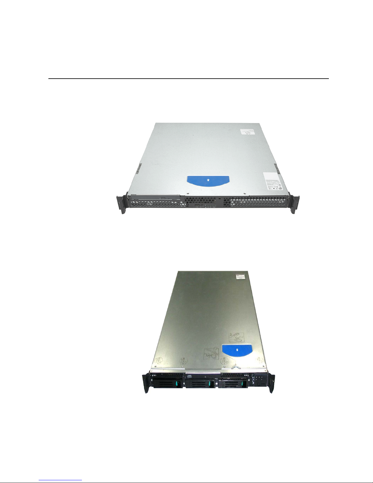
1 Server System Features
This chapter briefly describes the main features of the server system. This chapter
provides a illustrations of the product, a list of the server system features, and diagrams
showing the location of important components and connections on the server system.
®
Figure 1. Intel
Note: The figure above is shown with an optional optical drive installed.
Server System SR1530AH/SR1530AHLX
Note: The figure above is shown with an optional optical drive installed.
Figure 2. Intel
®
Server System SR1530HAHLX
Page 24
Table 2 s ummariz es the features of the server system.
®
Table 2. Intel
Server System SR1530AH / SR1530AHLX / SR1530HAHLX
Feature Summary
Feature Description
Dimensions (SR1530AH/
SR1530AHLX)
• 1.69 inches high (4.29 centimeters)
• 17 inches wide (43.18 centimeters)
• 20 inches deep (50.80 centimeters)
• 20 pounds (9 kilograms)
Dimensions
(SR1530HAHLX)
• 1.69 inches high (4.29 centimeters)
• 17 inches wide (43.18 centimeters)
• 25.5 inches deep ( centimeters)
• 23 pounds (10.43 kilograms)
Server Board One of the following:
®
• Intel
• Intel
Processor Support for one:
Server System SR1530AH: Intel® Server Board
S3000AH
®
Server Systems SR1530AHLX / SR1530HAHLX: Intel®
Server Board S3000AHLX
• Dual-Core Intel
®
Memory
• Intel
• Intel
• Intel
• Intel
• Four DIMM sockets supporting stacked DDR2 533/667 MHz
Pentium® processor Extreme Edition
®
Pentium® 4 processor
®
Pentium® D processor
®
Celeron® D processor
ECC or non-ECC unbuffered memory
• Support for up to 8 GB of total system memory
®
Chipset Intel
3000 chipset, consisting of:
®
• Intel
• Intel
• Intel
3000 Memory Controller Hub (MCH)
®
I/O Controller Hub (ICH7R)
®
6702 PXH-V PCI-X* Hub (S3000AHLX SKU only)
®
Xeon® processor 3000 sequence
2 Intel® Server System SR1530AH / SR1530AHLX / SR1530HAHLX
Page 25
Table 2. Intel® Server System SR1530AH / SR1530AHLX / SR1530HAHLX
Feature Summary
Feature Description
Peripheral Interfaces External connections:
• Stacked PS/2* ports for keyboard and mouse
• DB9 Serial A port
• Two RJ45 NIC connectors for 10/100/1000 Mb connections
• Four USB 2.0 ports
Internal connections:
• One USB port header, which supports two USB 2.0 ports
• One DH10 Serial B header
• Four Serial ATA connectors with embedded RAID 0/1/10
support.
• One ATA-100 connector
• ATX-compliant 24-pin, high-density 100-pin, and alternate 50-
pin control panel headers
I/O Control SMSC* SCH5027 controller
Video On-board ATI* ES1000 video controller with 16 MB DDR SDRAM
LAN Intel
®
10/100/1000 82541PI Gigabit Ethernet Controller
In addition, one of the following:
®
• Intel
• Intel
Server System SR1530AH: Intel® 10/100/1000 82573V
Gigabit Ethernet Controller
®
Server System SR1530AHLX: Intel® 10/100/1000
82573E Gigabit Ethernet Controller
Expansion Capabilities
(optional accessory
required)
Support for one of the following:
• One low-profile riser slot supporting a 1U PCI Express* riser
card
• One low-profile riser slot supporting a 1U PCI-X* riser card
Hard Drives SATA support, 3 Gb/s: capable of supporting up to two drives
Peripherals
Control Panel
(SR1530AH / SR1530AHLX) or three drives (SR1530HAHLX)
• Slimline bay for IDE optical drive (optional)
• One USB port
• Power / sleep button
• Status LED
• Power LED
• Hard drive activity LED
• NIC1 activity LED
• NIC2 activity LED
Power Supply One 350-watt power supply module
Fans
• Three non-redundant fans (SR1530AH / SR1530AHLX)
• Two non-redundant fans (SR1530HAHLX)
Intel® Server System SR1530AH / SR1530AHLX / SR1530HAHLX 3
Page 26
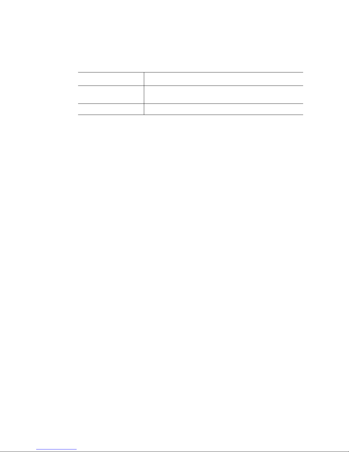
Table 2. Intel® Server System SR1530AH / SR1530AHLX / SR1530HAHLX
Feature Summary
Feature Description
USB
• One front panel USB port
• One internal USB header providing two USB ports
System Management Intel
®
System Management Software
4 Intel® Server System SR1530AH / SR1530AHLX / SR1530HAHLX
Page 27
Chassis Component Identification
This section helps you identify the components of your server system. If you are near the
system, you can also use the Quick Reference Label on the inside of the chassis cover to
assist in identifying components.
System Front Panel (SR1530AH / SR1530AHLX)
The front of the server system includes the following buttons and LEDs.
BA
A. USB Port E. Hard Disk Drive Activity LED
B. Power Button F. NIC1 LED
C. Not used G. NIC2 LED
D. System Power LED
Figure 3. Front Controls and LEDs (SR1530AH / SR1530AHLX)
E
D
GC
F
AF001000
Intel® Server System SR1530AH / SR1530AHLX / SR1530HAHLX 5
Page 28
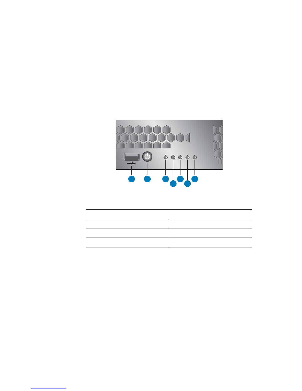
System Front Panel (SR1530HAHLX)
The front of the server system includes the following buttons and LEDs.
B
A
D
C
F E
AF001573
A. NIC1 LED D. HDD Activity LED
B. NIC2 LED E. USB Port
C. Power LED F. Power Button
Figure 4. Front Controls and LEDs (SR1530HAHLX)
6 Intel® Server System SR1530AH / SR1530AHLX / SR1530HAHLX
Page 29
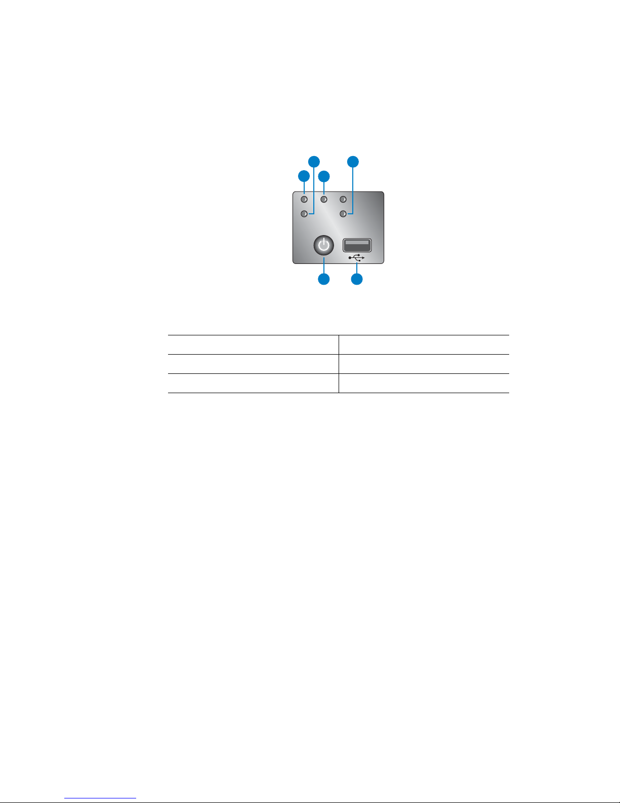
System Rear
A B C D E
GI H F
AF000999
A. AC Power Connector F. USB 0-1
B. Mouse G. NIC 2 (10/100/1000 Mb)
C. Serial Port A H. Video
D. NIC 1 (10/100/1000 Mb) I. Keyboard
E. PCI Add-in Card Slot
Figure 5. Back Panel Connectors
The NIC LEDs at the right and left of each NIC provide the following information.
Table 3. NIC LED Descriptions
LED LED State Description
Left Off No network connection
Solid Amber Network connection in place
Blinking Amber Transmit/receive activity
Right Off 10 Mbps connection (if left LED is on or blinking)
Solid Amber 100 Mbps connection
Solid Green 1000 Mbps connection
Intel® Server System SR1530AH / SR1530AHLX / SR1530HAHLX 7
Page 30
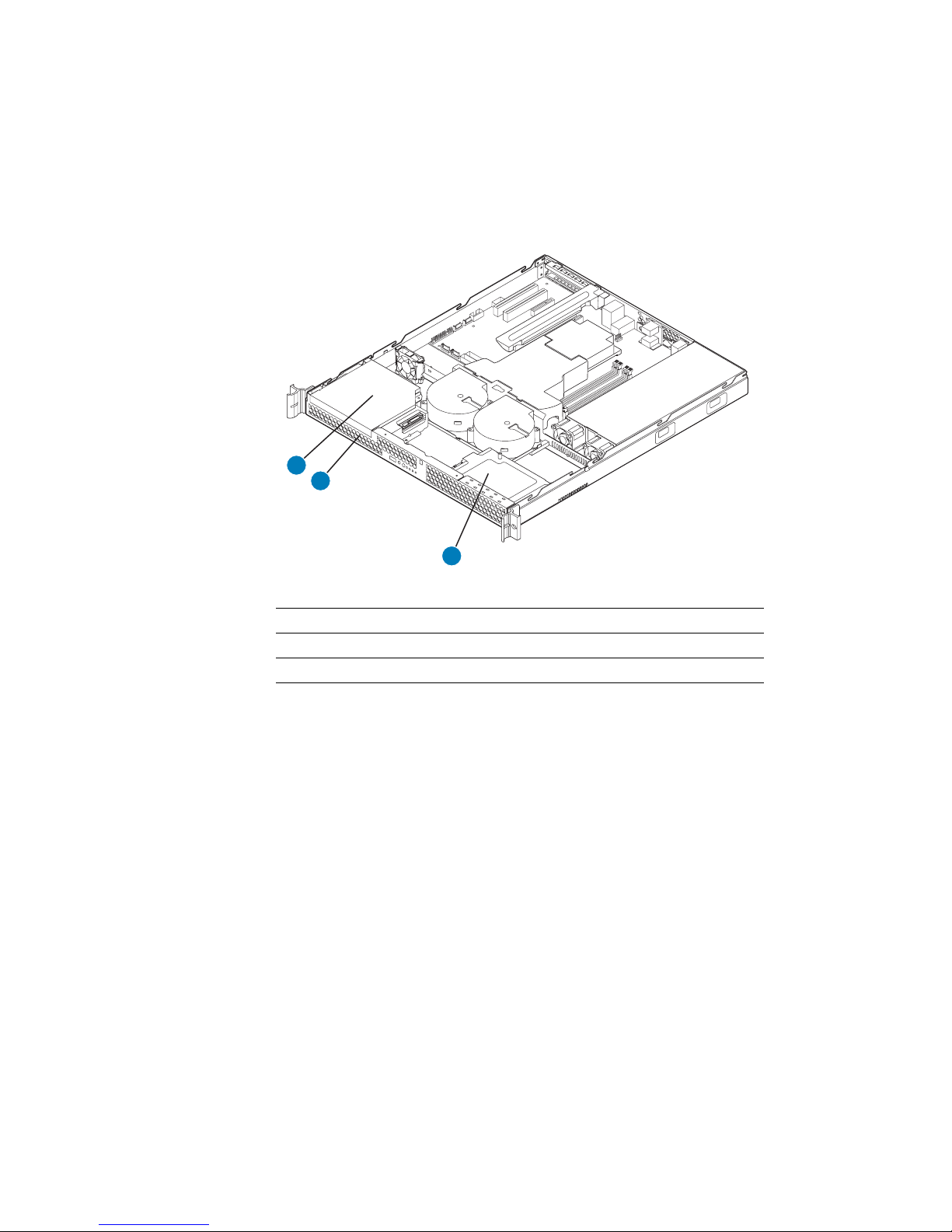
Peripheral Devices (SR1530AH / SR1530AHLX)
The server system provides locations and hardware for installing hard drives, slimline
CD-ROM drive, or DVD-ROM drive. The drives must be purchased separately. The
following figure shows the available options.
A
B
C
.
A. Slimline Optical Drive Bay
B. Hard Disk Drive Bay HDD0 (located under the slimline optical drive bay)
C. Hard Disk Drive Bay HDD1
AF001074
Figure 6. Optional Peripherals (SR1530AH / SR1530AHLX)
8 Intel® Server System SR1530AH / SR1530AHLX / SR1530HAHLX
Page 31
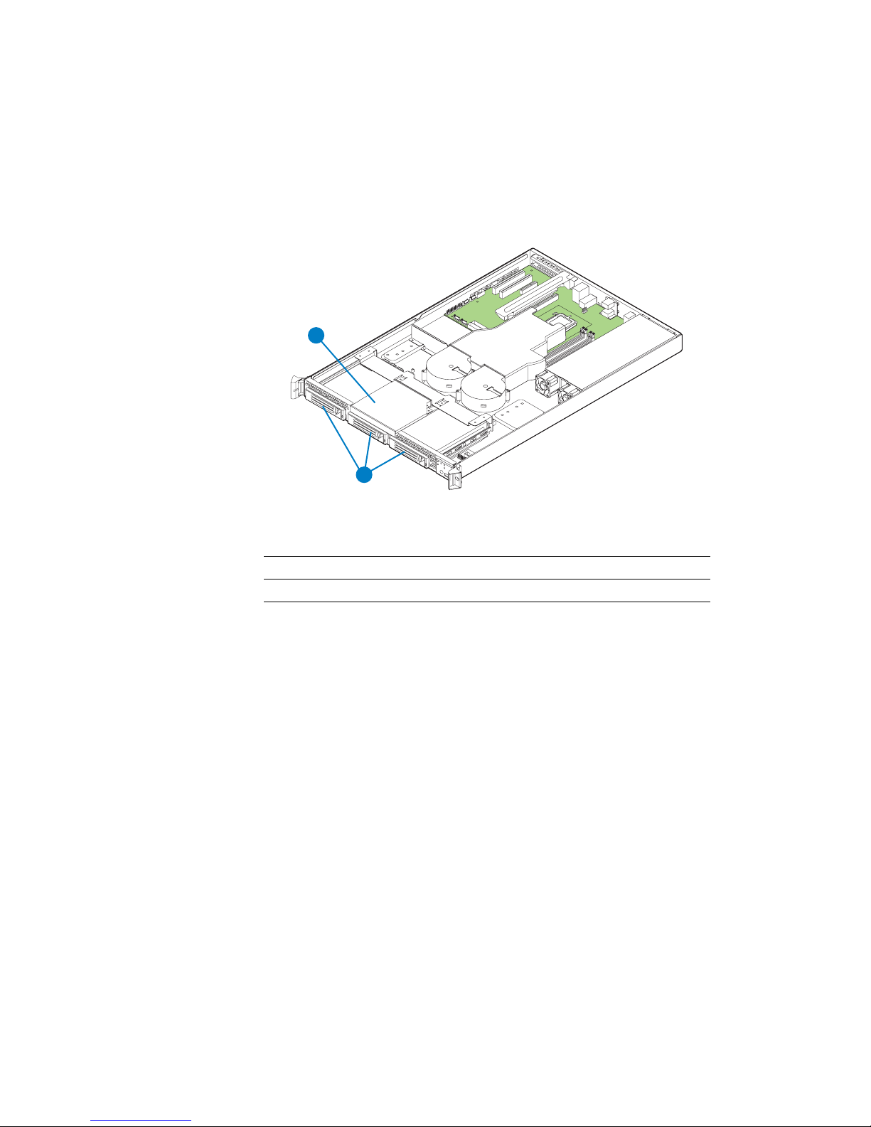
Peripheral Devices (SR1530HAHLX)
The server system provides locations and hardware for installing hard drives, slimline
CD-ROM drive, or DVD-ROM drive. The drives must be purchased separately. The
following figure shows the available options.
A
B
.
AF001574
Hard Disk Drives
The Intel® Server System SR1530AH, the Intel® Server System SR1530AHLX, and the
®
Server System SR1530HAHLX each provide four SATA ports and one IDE
Intel
connection. The four SATA ports are near the front left side of the server board. An IDE
device can be connected to the standard IDE connector located near the SATA ports.
For instructions on installing hard drives, see “Installing and Removing a Hard Drive
(SR1530AH / SR1530AHLX)” on page 41.
Note: Drives can consume up to 17 watts of power each. Drives must be specified to run at a
maximum ambient temperature of 45C.
Note: The Intel
Serial ATA (SAT A) hard drives. See “Server System References” on page x for an Internet
link to a list of supported hardware.
A. Slimline Optical Drive Bay
B. Hard Disk Drive Bays
Figure 7. Optional Peripherals (SR1530HAHLX)
®
Server System SR1530AH / SR1530AHLX / SR1530HAHLX do not support all
Intel® Server System SR1530AH / SR1530AHLX / SR1530HAHLX 9
Page 32

Slimline Optical Drive Carrier
One slimline drive carrier is included with your server system; the optical drive must be
purchased separately. To use the slimline CD-ROM drive provided by Intel, use order
code AXXSCD. To use the slimline DVD drive provided by Intel, use order code
AXXDVDROM. To use the slimline DVD CDR drive provided by Intel, use order code
AXXDVDCDR.
®
Note: The Intel
all slimline optical drives. See Table 1 on page x for an Internet link to a list of supported
hardware . Intel provides accessory kits for these drives.
For installation instructions for an optical drive, see “Installing or Removing a Slimline
Optical Drive (SR1530AH / SR1530AHLX)” on page 50.
Server System SR1530AH / SR1530AHLX / SR1530HAHLX does not support
10 Intel® Server System SR1530AH / SR1530AHLX / SR1530HAHLX
Page 33

Internal Components (SR1530AH / SR1530AHLX)
D
C
B
A
E
K
F
G
J
H
I
A
A. Rack Handles (two) G. System Memory DIMM Sockets
B. PCI Cooling Fan H. System Blower Fans (two)
C. Processor Air Duct I. Front Panel Board
D. PCI Add-in Card Bracket J. Control Panel
E. Processor and Heat Sink K. Slimline Optical Drive Bay
F. Power Supply
Figure 8. System Components (SR1530AH / SR1530AHLX)
AF000970
Intel® Server System SR1530AH / SR1530AHLX / SR1530HAHLX 11
Page 34

Internal Components (SR1530HAHLX)
G
F
E
D
C
B
A
L
K
A
H
I
J
AF001575
A. Rack Handles (two) G. PCI Add-in Card Bracket
B. Slimline Optical Drive Bay H. Processor and Heat Sink
C. PCI Air Baffle I. Power Supply
D. System Blower Fans (two) J. Front Panel Board
E. Processor Air Duct K. Control Panel
F. Server Board L. Hard Drive Carriers (three)
Figure 9. System Components (SR1530HAHLX)
12 Intel® Server System SR1530AH / SR1530AHLX / SR1530HAHLX
Page 35

Server Board Connectors / Components
A B C D JH I K LFE G
M
N
PP
OO
NN
MM
LL
KK
HH
GG
FF
JJ
II
DD BB
CCEE
Z YAAX W V U T S R Q
O
P
AF000537
A. Video Memory O. Processor Socket CC. SMSC* SCH5027 Super I/O
B. PCI 32/33 Slot 2 P. Processor Fan DD. SATA Port 2
C. ATI* ES1000 Video Controller Q. DIMM Sockets (2B and 2A) EE. Intel® 82801 ICH7R
D. PCI Express* x4 Slot 3 R. DIMM Sockets (1B and 1A) FF. Front Panel Connector
E. Intel® 82541PI LAN Controller S. System Front DIMM Blower Header GG. SCSI HDD LED Header
F. PCI-X* 64/133 Slot 5 T. System Front Processor Blower Header HH. SATA Port 1
G. LAN SPI Flash U. Chassis Intrusion Header II. Clear CMOS Jumper
H. Intel
I. Intel
®
82573E LAN Controller V. Intel® S3000 MCH JJ. SATA Port 0
®
Adaptive Slot, Slot 6 W. CMOS Battery KK. BIOS SPI Flash
J. Clock Generator X. 2x12 Main Power Connector LL. External USB Connector
K. Back Panel Connectors Y. Front System Fan MM. SPI/FWH Select Header
L. Diagnostic POST LEDs Z. Floppy Connector NN. HSBP Header
M. Rear System Fan AA. PATA IDE Connector OO. Intel
N. 2x4 Power Connector BB. SATA Port 3 PP. PCI 32/33 Slot 1
Figure 10. S3000AHLX Connector and Component Locations
Intel® Server System SR1530AH / SR1530AHLX / SR1530HAHLX 13
®
6702 PXH-V Controller
Page 36

A B C D E JI KGF H
L
M
NN
MM
LL
KK
JJ
HH
GG
FF
EE
II
CC AA
BBDD
Y XZW V U T S R Q P
N
O
AF000538
A. Video Memory O. Processor Fan BB. SMSC* SCH5027 Super I/O
B. PCI 32/33 Slot 2 P. DIMM Sockets (2B and 2A) CC. SATA Port 2
C. ATI* ES1000 Video Controller Q. DIMM Sockets (1B and 1A) DD. Intel® 82801 ICH7R
D. PCI Express* x4 Slot 3 R. System Front DIMM Blower Header EE. Front Panel Connector
E. PCI Express x8 Slot 5 S. System Front Processor Blower Header FF. SCSI HDD LED Header
F. Intel
G. PCI Express x8 Slot 6 U. Intel
®
82541PI Lan Controller T. Chassis Intrusion Header GG. SATA Port 1
®
S3000 MCH HH. Clear CMOS Jumper
H. LAN SPI Flash V. Battery II. SATA Port 0
I. Intel® 82573E LAN Controller W. 2x12 Main Power Connector JJ. BIOS SPI Flash
J. Clock Generator X. Front System Fan KK. External USB Connector
K. Back Panel Connectors Y. Floppy Connector LL. SPI/FWH Select Header
L. Rear System Fan Z. PATA IDE Connector MM.HSBP Header
M. 2x4 Power Connector AA. SATA Port 3 NN. PCI 32/33 Slot 1
N. Processor Socket
Figure 11. S3000AH Connector and Component Locations
14 Intel® Server System SR1530AH / SR1530AHLX / SR1530HAHLX
Page 37

Configuration Jumpers
NIC1
3
NVM
Protect
Mode
J4A1
Protect
2
Default
CMOS
CLR
J1G3
BIOS
J1H3
Remove jumper for BIOS recovery
Default
2
CLEAR
CMOS
3
3
2
Default
AF000525
Jumper Name Jumper Purpose
NIC1 NVM Protect Mode If pins 2-3 are jumpered, the Intel
programmed. When pins 1-2 are jumpered, the Intel
®
82573E/V firmware will be
®
82573E/V
firmware is protected and will not be updated. These pins should be
jumpered on 1-2 for normal operation.
CMOS Clear If pins 2-3 are jumpered, the CMOS settings will be cleared on the
next reset. These pins should be jumpered on 1-2 for normal
operation.
BIOS Recovery If pins 2-3 are jumpered, the BIOS in the lower bank will be selected
on the next reset. These pins should be jumpered on 1-2 for normal
operation.
Intel® Server System SR1530AH / SR1530AHLX / SR1530HAHLX 15
Figure 12. Configuration Jumper Descriptions
Page 38

RAID Support
The Intel® Server System SR1530AH / SR1530AHLX / SR1530HAHLX provides SATA
(3.0 Gb/s) support.The SATA controller embedded in the Intel
S3000AHLX supports both 1.5 and 3.0 Gbps data transfer rates.
The BIOS Setup utility provides multiple drive configuration options on the Advanced |
ATA Controller setup page, some of which affect the ability to configure RAID. The
“Onboard SATA Controller” option is enabled by default. When this option is enabled, the
“SATA Mode” option can be set to either Legacy or Enhanced. The Legacy and Enhanced
modes affect the RAID configuration as follows:
®
Server Board S3000AH /
• The legacy mode does not provide RAID support.
• The enhanced mode is required for RAID configurations.
When the enhanced mode is selected, you can choose to enable or disable “AHCI Mode”
or “Configure SATA as RAID”. Intel
by the option, “Configure SATA as RAID.” The Intel
Technology II feature provides RAID modes 0, 1, and 10.
Notes: For assistance in navigating through the F2 BIOS Setup utility, see the Intel
Board S3000AH Technical Product Specification.
For information on setting up RAID, see the RAID Software Guide that is included on the
®
Intel
Server Deployment Toolkit 2.0 CD.
®
Embedded Server RAID Technology II is enabled
®
Embedded Server RAID
®
Server
Hardware Requirements
To avoid integration difficulties and possible board damage, your system must meet the
requirements outlined below. For a list of qualified components, see the links under
"Server System References."
Processor
Support for one processor from the following list:
• Dual-Core Intel
• Intel
• Intel
• Intel
• Intel
For a complete list of supported processors, see the links under “Server System
References” on page x.
®
Pentium® processor Extreme Edition
®
Pentium® 4 processor
®
Pentium® D processor
®
Celeron® D processor
®
Xeon® processor 3000 sequence
16 Intel® Server System SR1530AH / SR1530AHLX / SR1530HAHLX
Page 39

Memory
Note: Installing only three DIMMs is not supported. Use DIMMs that are the same type and
The Intel® Server System SR1530AH / SR1530AHLX / SR1530HAHLX provides four
DIMM sockets across two banks, bank 1 and bank 2. Bank 1 consists of DIMM sockets
1A and 1B. Bank 2 consists of DIMM sockets 2A and 2B.
A minimum of one 256-MB DIMM is required in DIMM socket 1A. This uses singlechannel interleave. However, for dual-channel interleave, providing optimum
performance, a minimum of two DIMMs should be installed in DIMM sockets 1A and
2A. To operate in dual-channel dynamic paging mode, the following conditions must be
met:
• Populate two identical DIMMs in sockets DIMM1A and DIMM 1B.
• Populate four identical DIMMs in each socket location.
speed. Use of identical DIMMs is preferred.
DIMMs must meet the following requirements:
• Use only DIMMs with DDR2 DRAM technology.
• Use only DDR2-533 and DDR2-667 stacked DIMM modules.
In determining your memory requirements, the need for memory sparing or memory
mirroring must be considered. For a complete list of supported memory DIMMs, see the
links under “Server System References” on page x.
Intel® Server System SR1530AH / SR1530AHLX / SR1530HAHLX 17
Page 40

18 Intel® Server System SR1530AH / SR1530AHLX / SR1530HAHLX
Page 41

2 Server Utilities
Using the BIOS Setup Utility
This section describes the BIOS Setup Utility options, which is used to change server
configuration defaults. You can run BIOS Setup with or without an operating system
being present. See the links under “Server System References” on page x for a link to the
®
Server Board S3000AH Technical Product Specification where you will find details
Intel
about specific BIOS setup screens.
Starting Setup
You can enter and start BIOS Setup under several conditions:
• When you turn on the server, after POST completes the memory test.
• When you have moved the CMOS jumper on the server board to the “Clear CMOS”
position (enabled).
In the two conditions listed above, during the Power On Self Test (POST), you will see
this prompt:
Press <F2> to enter SETUP
In a third condition, when CMOS/NVRAM has been corrupted, you will see other
prompts but not the <F2> prompt:
Warning: CMOS checksum invalid
Warning: CMOS time and date not set
In this condition, the BIOS will load default values for CMOS and attempt to boot.
If You Cannot Access Setup
If you are not able to access BIOS Setup, you might need to clear the CMOS memory. For
instructions on clearing the CMOS, see “Clearing the CMOS” on page 23.
Setup Menus
Each BIOS Setup menu page contains a number of features. Except for those features that
are provided only to display automatically configured information, each feature is
associated with a value field that contains user-selectable parameters. These parameters
can be changed if the user has adequate security rights. If a value cannot be changed for
any reason, the feature's value field is inaccessible.
Page 42

“Setup Menu Key Use” describes the keyboard commands you can use in the BIOS Setup
menus.
Table 4. Setup Menu Key Use
Key to Press Description
<F1> Pressing the <F1> key on any menu invokes the general help window.
Left and right arrows The left and right arrow keys are used to move between the major menu
pages. The keys have no affect if a submenu or pick list is displayed.
Up arrow Select Item up - The up arrow is used to select the previous value in a
menu item's option list, or a value field pick list. Pressing the <Enter> key
activates the selected item.
Down arrow Select Item down - The down arrow is used to select the next value in a
menu item's option list, or a value field pick list. Pressing the <Enter> key
activates the selected item.
<F5> or <-> Change Value - The minus key or the <F5> function key is used to
change the value of the current item to the previous value. This key
scrolls through the values in the associated pick list without displaying
the full list.
<F6> or <+> Change Value - The plus key or the <F6> function key is used to change
the value of the current menu item to the next value. This key scrolls
through the values in the associated pick list without displaying the full
list. On 106-key Japanese keyboards, the plus key has a different scan
code than the plus key on the other keyboard, but it has the same effect.
<Enter> Execute Command - The <Enter> key is used to activate submenus
when the selected feature is a submenu, or to display a pick list if a
selected feature has a value field, or to select a sub-field for multi-valued
features like time and date. If a pick list is displayed, the <Enter> key will
undo the pick list, and allow another selection in the parent menu.
<Esc> Exit - The <Esc> key provides a mechanism for backing out of any field.
<F9> Setup Defaults - Pressing <F9> causes the following to appear:
This key will undo the pressing of the <Enter> key. When the <Esc> key
is pressed while editing any field or selecting features of a menu, the
parent menu is re-entered. When the <Esc> key is pressed in any
submenu, the parent menu is re-entered. When the <Esc> key is
pressed in any major menu, the exit confirmation window is displayed
and the user is asked whether changes can be discarded.
Setup Confirmation
Load default configuration now?
[Yes] [No]
If “Yes” is selected and the <Enter> key is pressed, all Setup fields are
set to their default values. If “No” is selected and the <Enter> key is
pressed, or if the <Esc> key is pressed, the user is returned to where
they were before <F9> was pressed without affecting any existing field
values.
20 Intel® Server System SR1530AH / SR1530AHLX / SR1530HAHLX
Page 43

Key to Press Description
<F10> Save and Exit - Pressing the <F10> key causes the following message
to appear:
If “Yes” is selected and the <Enter> key is pressed, all changes are
saved and Setup is exited. If “No” is selected and the <Enter> key is
pressed, or the <Esc> key is pressed, the user is returned to where they
were before <F10> was pressed without affecting any existing values.
Upgrading the BIOS
The upgrade utility allows you to upgrade the BIOS in flash memory. The code and data in
the upgrade file include the following:
• On-board system BIOS, including the recovery code, BIOS Setup Utility, and
strings.
• On-board video BIOS, and other option ROMs for devices embedded on the server
board.
Table 4. Setup Menu Key Use
Setup Confirmation
Save Configuration changes and exit now?
[Yes] [No]
• OEM binary area
• Microcode
• A way to change the BIOS language
Preparing for the Upgrade
The steps below explain how to prepare to upgrade the BIOS, including ho w to record th e
current BIOS settings and how to obtain the upgrade utility.
Note: In the unlikely event that a BIOS error occurs during the BIOS update pr ocess, a r ecovery
process may need to be followed to return the system to service. See “Server System
References” on page x for a link to necessary software and instructions.
Recording the Current BIOS Settings
1. Boot the computer and press <F2> when you see the message:
Press <F2> Key if you want to run SETUP
2. Write down the current settings in the BIOS Setup program.
Note: Do not skip step 2. You will need these settings to configure your server at the end of the
procedure.
Intel® Server System SR1530AH / SR1530AHLX / SR1530HAHLX 21
Page 44

Obtaining the Upgrade
Download the BIOS image file to a temporary folder on your hard drive. See “Server
System References” on page x for a link to the update software.
Note: Review the instructions and release notes that are provided in the readme file distributed
with the BIOS image file before attempting a BIOS upgrade. The release notes contain
critical information regarding jumper settings, specific fixes, or other information to
complete the upgrade.
Upgrading the BIOS
Follow the instructions in the readme file that came with the BIOS upgrade. When the
update completes, remove the bootable media from which you performed the upgrade.
Caution: Do not power down the system during the BIOS update process!
Note: You may encounter a CMOS Checksum error or other problem after reboot. If this
happens, shut down the system and boot it again. CMOS checksum err ors r equir e that you
enter Setup, check your settings, save your settings, and exit Setup.
22 Intel® Server System SR1530AH / SR1530AHLX / SR1530HAHLX
Page 45

Clearing the CMOS
If you are not able to access the BIOS setup screens, the CMOS Clear jumper will need to
be used to reset the configuration RAM.
1. Power down the system and disconnect the AC power.
2. Open the server.
3. Move the jumper from the normal operation position, CMOS Clear by BMC, at
pins 1 and 2 to the CMOS Clear Force Erase position, covering pins 2 and 3.
CMOS
CLR
J1G3
Default
2
CLEAR
CMOS
3
AF000526
Figure 13. Clear CMOS Jumper
4. Reconnect the AC power, power up the system.
5. When the system begins beeping, power it down and disconnect the AC power.
6. Return the CMOS Clear jumper to the CMOS Clear by BMC location, covering
pins 1 and 2.
7. Close the server chassis.
8. Reconnect the AC power and power up the system.
Intel® Server System SR1530AH / SR1530AHLX / SR1530HAHLX 23
Page 46

24 Intel® Server System SR1530AH / SR1530AHLX / SR1530HAHLX
Page 47

3 Hardware Installations and
Upgrades
Caution: No components in the Intel® Server System SR1530AH / SR1530AHLX are hot swappable.
Before removing or installing any component in this server system, you must first take the
server out of service, turn off all peripheral devices connected to the system, turn off the
system by pressing the power button, and unplug the AC power cord from the system or
wall outlet.
Note: Some components in the Intel
be noted as such in the instructions that follow where applicable.
Note: Most of the illustrations in this chapter show the Intel
SR1530AHLX with an optional optical drive installed. The instructions for removing and
installing components are the same for the Intel
otherwise noted. When instructions differ, separate illustrations will be shown for the
®
Server System SR1530HAHLX.
Intel
®
Server System SR1530HAHLX are hot swappable and will
Before You Begin
Before working with your server product, pay close attention to the “Safety Information”
on page iii.
Tools and Supplies Needed
• Phillips* (cross head) screwdriver, #1 bit and #2 bit
• Antistatic wrist strap and conductive foam pad (recommended)
®
Server System SR1530AH /
®
Server System SR1530HAHLX, unless
System References
All references to left, right, front, top, and bottom assume the reader is facing the front of
the server system as it would be positioned for normal operation.
Page 48

Removing and Installing the Front Bezel
The front bezel is available as an optional accessories for the Intel® Server System
SR1530AH / SR1530AHLX / SR1530HAHLX. Note the orientation in the figures below
and make sure you position your bezel as shown.
Removing the Front Bezel
Use the steps below if your system includes a front bezel.
1. Unlock the bezel.
2. Pull the bezel from the server system.
26 Intel® Server System SR1530AH / SR1530AHLX / SR1530HAHLX
AF001059
Figure 14. Removing the Front Bezel
Page 49
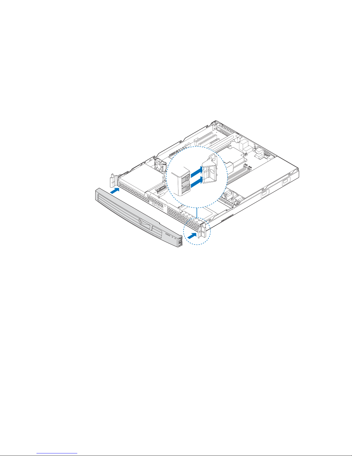
Installing the Front Bezel
The front bezel is optional.
1. At each end of the bezel, line up the center notch on the bezel with the center guide
on the rack handles.
2. Push the bezel onto the front of the server system until it clicks into place.
3. Lock the bezel.
Figure 15. Installing the Front Bezel
AF001058
Intel® Server System SR1530AH / SR1530AHLX / SR1530HAHLX 27
Page 50

Removing and Installing the Server Cover
Removing the Server System Cover
The server system must be operated with the server system cover in place to ensure proper
cooling. You will need to remove the cover to add or replace components inside of the
server.
None of the internal components are hot-swappable. Before removing the server system
cover, power down the server and unplug all peripheral devices and the AC power cable.
Note: A nonskid surface or a stop behind the server system may be needed to prevent the server
system from sliding on your work surface.
1. Observe the safety and ESD precautions at the beginning of this book. See “Safety
Information” on page iii.
2. Turn off all peripheral devices connected to the server. Turn off the server.
3. Disconnect the AC power cord.
4. SR1530AH/SR1530AHLX: Remove the two screws at the front of the chassis. See
letter “A” in the figure below.
5. SR1530AH/SR1530AHLX: Loosen the screw at the rear of the chassis. See letter
“B” in the figure below.
6. SR1530AH/SR1530AHLX: Push rearward on the blue grip point at the front of the
server. Slide the cover back until it stops and then lift the cover upward to remove
it. See letter “C”.
B
C
A
AF000662
Figure 16. Removing the Server System Cover (SR1530AH/SR1530AHLX)
28 Intel® Server System SR1530AH / SR1530AHLX / SR1530HAHLX
Page 51

7. SR1530HAHLX: Remove the four screws at the front of the chassis. See letter “A”
in the figure below .
8. SR1530HAHLX: Push rearward on the blue grip point at the front of the server.
Slide the cover back until it stops and then lift the cover upward to remove it. See
letter “B”.
B
A
AF001578
Figure 17. Removing the Server System Cover (SR1530HAHLX)
Intel® Server System SR1530AH / SR1530AHLX / SR1530HAHLX 29
Page 52

Installing the Server System Cover
1. Observe the safety and ESD precautions at the beginning of this book. See “Safety
Information” on page iii.
2. SR1530AH/SR1530AHLX: Place the cover over the server system so that the side
edges of the cover sit just inside the server system sidewalls. Slide the cover
forward. See letter “A” in the figure below.
3. SR1530AH/SR1530AHLX: Tighten the screw at the rear of the server. See letter
“B” in the figure.
4. SR1530AH/SR1530AHLX: Install the two screws at the front of the server. See
letter “C”.
B
A
C
AF000663
Figure 18. Installing the Server System Cover (SR1530AH/SR1530AHLX)
5. SR1530HAHLX: Place the cover over the server system so that the side edges of
the cover sit just inside the server system sidewalls. Slide the cover forward. See
letter “A” in the figure below.
6. SR1530HAHLX: Install the four screws at the front of the server. See letter “B”.
30 Intel® Server System SR1530AH / SR1530AHLX / SR1530HAHLX
Page 53

A
B
AF001579
Figure 19. Installing the Server System Cover (SR1530HAHLX)
7. Reconnect all peripheral devices and the AC power cord.
Removing and Installing the Processor Air Duct
Always operate your server system with the processor air duct in place. The air duct is
required for proper airflow within the server system.
Removing the Processor Air Duct
1. Observe the safety and ESD precautions at the beginning of this book. See “Safety
Information” on page iii.
2. Power down the server and unplug all peripheral devices and the AC power cable.
3. Remove the server system cover. For instructions, see “Removing the Server
System Cover”.
4. Lift the processor air duct from its location behind the two system blower fans (see
Figure 20 for SR1530AH/SR1530AHLX; see for SR1530HAHLX).
Intel® Server System SR1530AH / SR1530AHLX / SR1530HAHLX 31
Page 54

AF000664
Figure 20. Removing the Processor Air Duct (SR1530AH/SR1530AHLX)
Figure 21. Removing the Processor Air Duct (SR1530HAHLX)
32 Intel® Server System SR1530AH / SR1530AHLX / SR1530HAHLX
AF001580
Page 55
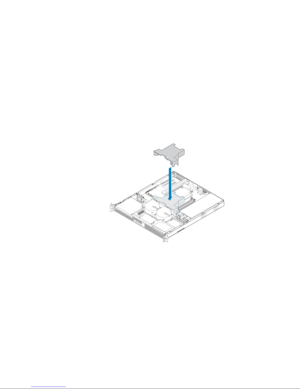
Installing the Processor Air Duct
1. Observe the safety and ESD precautions at the beginning of this book. See “Safety
Information” on page iii.
2. Power down the server and unplug all peripheral devices and the AC power cable.
3. Remove the server system cover. For instructions, see “Removing the Server
System Cover” on page 28.
4. Lower the air duct into place, insert the two hooks at the front of the processor air
duct into the corresponding slots on the bracket behind the two system blower fans
(see Figure 22for SR1530AH/SR1530AHLX); see Figure 23 for SR1530HAHLX).
Use caution not to pinch or disengage cables that may be near or under the air duct.
5. Install the server system cover. For instructions, see “Installing the Server System
Cover”.
Figure 22. Installing the Processor Air Duct (SR1530AH/SR1530AHLX)
Intel® Server System SR1530AH / SR1530AHLX / SR1530HAHLX 33
AF000665
Page 56

AF001581
Figure 23. Installing the Processor Air Duct (SR1530HAHLX)
Installing and Removing Memory
Caution: The memory is NOT hot swappable. Before removing or replacing any memory DIMM,
you must first take the server out of service, turn off all peripheral devices connected to
the system, turn off the system by pressing the power button, and unplug the AC power
cord from the system or wall outlet.
The silkscreen on the board for the DIMMs displays DIMM A1, DIMM A2, DIMM B1,
and DIMM B2 starting from the center of the board. See “Memory” on page 17 for a
discussion of the memory requirements and options. See “Server System References” on
page x for a link to the list of tested DIMMs.
Installing DIMMs
To install DIMMs, follow these steps:
1. Observe the safety and ESD precautions at the beginning of this book. See “Safety
Information” on page iii.
2. Power down the server and unplug all peripheral devices and the AC power cable.
3. Remove the server system cover. For instructions, see “Removing the Server
System Cover” on page 28.
34 Intel® Server System SR1530AH / SR1530AHLX / SR1530HAHLX
Page 57

4. Locate the DIMM sockets. See Figure 24.
C
D
B
A
DIMM 1A
Socket
DIMM 2A
Socket
DIMM 2B
Socket
DIMM 1B
Socket
AF000534
Figure 24. Installing the Memory
5. Make sure the clips at both ends of the DIMM socket(s) are pushed outward to the
open position. See letter “A” in Figure 24.
6. Holding the DIMM by the edges, remove it from its anti-static package.
7. Position the DIMM above the socket. Align the notch on the bottom edge of the
DIMM with the key in the DIMM socket. See letter “B” in the figure.
8. Insert the bottom edge of the DIMM into the socket. See letter “C” in the figure.
9. When the DIMM correctly positioned, push down on the top edge of the DIMM
until the retaining clips snap into place.
10. Make sure the clips are firmly in place. See letter “D” in the figure.
11. Install the server system cover. For instructions, see “Installing the Server System
Cover”.
Intel® Server System SR1530AH / SR1530AHLX / SR1530HAHLX 35
Page 58

Removing DIMMs
To remove a DIMM, follow these steps:
1. Observe the safety and ESD precautions at the beginning of this book. See “Safety
Information” on page iii.
2. Power down the server and unplug all peripheral devices and the AC power cable.
3. Remove the server system cover. For instructions, see “Removing the Server
System Cover” on page 28.
4. Locate the DIMM sockets. See Figure 24.
5. Gently spread the retaining clips at each end of the socket. The DIMM lifts from
the socket.
6. Holding the DIMM by the edges, lift it from the socket, and store it in an anti-static
package.
7. Install the server system cover. For instructions, see “Installing the Server System
Cover”.
36 Intel® Server System SR1530AH / SR1530AHLX / SR1530HAHLX
Page 59

Replacing the Processor
Note: This manual assumes a processor is already installed and you are re ferring to these steps
to replace your pr ocessor. If you are setting up this system for the first time, see the Quick
Start User’s Guide that was included in the product box.
Caution: Use only processors that have been validated to work with this server board. See “Server
System References” on page x for a link to the list of compatible processor(s).
Caution: ESD and handling pr ocessors: Reduce the risk of electrostatic dischar ge (ESD) damage to
the processor by doing the following: (1) Touch the metal chassis before touching the
processor or server board. Keep part of your body in contact with the metal chassis to
dissipate the static charge while handling the processor. (2) Avoid moving around
unnecessarily.
Removing the Heat Sink and Processor
1. Observe the safety and ESD precautions at the beginning of this book. See “Safety
Information” on page iii.
2. Power down the server and unplug all peripheral devices and the AC power cable.
3. Remove the server system cover. For instructions, see “Removing the Server
System Cover” on page 28.
4. Loosen the four captive screws on the corners of the heat sink.
5. Twist the heat sink slightly to break the seal between the heat sink and the
processor.
6. Lift the heat sink from the processor. If it does not pull up easily, twist the heat sink
again. Do not force the heat sink from the processor. Doing so could damage the
processor.
7. Lift the processor lever.
8. Raise the CPU load plate.
9. Remove the processor.
10. If installing a replacement processor, see “Installing the Processor” on page 38.
Otherwise, install the protective socket cover over the empty processor socket and
then reinstall the chassis cover.
Intel® Server System SR1530AH / SR1530AHLX / SR1530HAHLX 37
Page 60

Installing the Processor
To install a processor, follow these instructions:
1. Observe the safety and ESD precautions at the beginning of this book. See “Safety
Information” on page iii.
2. Power down the server and unplug all peripheral devices and the AC power cable.
3. Remove the server system cover. For instructions, see “Removing the Server
System Cover” on page 28.
4. Locate the processor socket and raise the socket handle completely. See Figure 25.
Figure 25. Lifting the Processor Socket Handle
5. Push the rear tab with your finger to slightly lift the front of the load plate. Raise the
load plate completely. Raise the CPU load plate (see Figure 26).
AF000528
A
B
AF000529
Figure 26. Opening the Load Plate
Caution: Do not touch the socket pins; they are very sensitive and easily damaged.
38 Intel® Server System SR1530AH / SR1530AHLX / SR1530HAHLX
Page 61

6. Remove the processor from the packaging box and remove the protective shipping
cover. See Figure 27.
A
AF000531
Figure 27. Removing the Shipping Cover
7. Orient the processor with the socket so the processor cutouts match the socket
notches. See letter “A” in the figure below.
8. Set the processor into place as shown by letter B.
A
B
AF000532
Figure 28. Installing the Processor
Note: Make sure the alignment triangle mark and the alignment triangle cutout align correctly.
9. Remove the protective socket cover. See Figure 29.
A
B
AF000530
Figure 29. Removing the Protective Socket Cover
Note: Retain the protective socket cover for use when removing a processor that will not be
replaced.
Intel® Server System SR1530AH / SR1530AHLX / SR1530HAHLX 39
Page 62
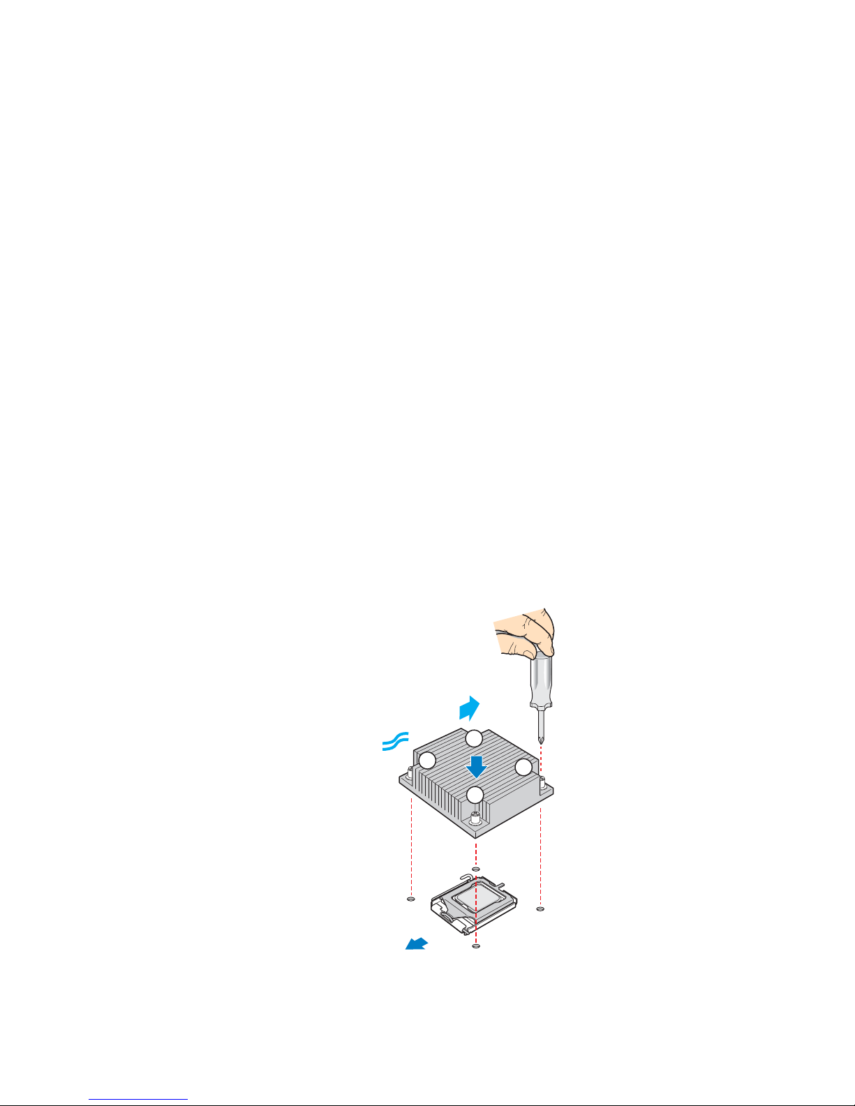
10. Lower the CPU load plate.
11. Lower the socket lever.
12. Install the heat sink. For instructions, see “Installing the Heat Sink”.
Installing the Heat Sink
Install your processor before installing the heat sink. For instructions, see “Installing the
Processor” on page 38.
Caution: The heat sink has Thermal Interface Material (TIM) located on the bottom of it. Use
caution when you unpack the heat sink so you do not damage the TIM.
1. Remove the protective cover from the TIM on the underside of the heat sink. Do
not touch the TIM.
2. Orient the heat sink over the processor as shown by Figure 30. The fins must be
positioned as shown to provide correct airflow through the system.
3. Set the heat sink over the processor, lining up the four captive screws with the four
posts surrounding the processor.
4. Loosely screw in the captive screws on the heat sink corners in a diagonal manner
as shown by the four circled numbers in the figure below. Do no fully tighten one
screw before tightening another.
5. Gradually and equally tighten each captive screw in the same order until each is
firmly tightened.
AIRFLOW
2
3
1
4
Chassis
Front
AF001049
40 Intel® Server System SR1530AH / SR1530AHLX / SR1530HAHLX
Figure 30. Installing the Heat Sink
Page 63

6. Reinstall and reconnect any parts you removed or disconnected to reach the
processor sockets.
7. Install the server system cover. For instructions, see “Installing the Server System
Cover”.
Installing and Removing a Hard Drive
(SR1530AH / SR1530AHLX)
Caution: The hard drives are NOT hot swappable. Before removing or replacing a hard drive, you
must first take the server out of service, turn off all peripheral devices connected to the
system, turn off the system by pressing the power button, and unplug the AC power cord
from the system or wall outlet.
Up to two SATA drives can be installed. The HDD0 drive bay is at the left side of the
chassis, underneath the optional CD-ROM drive. The HDD1 drive bay is at the right side
of the chassis. The drives do not need to be installed in order; HDD1 can be installed
before HDD0.
Note: The server system does not support all hard drives. See “Server System References” on
page x for an Internet link to a list of supported hardware.
Installing a Hard Disk Drive (SR1530AH/SR1530AHLX)
Note: If you are replacing an hard drive, see “Removing a Hard Disk Drive (SR1530AH/
SR1530AHLX)” on page 45 for instructions first. Return to these steps when directed.
1. Observe the safety and ESD precautions at the beginning of this book. See “Safety
Information” on page iii.
2. Power down the server. Unplug all peripheral devices and the AC power cable.
3. Remove the server system cover. For instructions, see “Removing the Server
System Cover” on page 28.
4. Locate the drive position you want to use. See Figure 31.
Intel® Server System SR1530AH / SR1530AHLX / SR1530HAHLX 41
Page 64

HDD 0
HDD 1
AF000666
Figure 31. Locating Drive Positions (SR1530AH/SR1530AHLX)
5. HDD1 location only: Slide the power cables from the cable clip that is located on
the top of the hard drive carrier.
6. Remove the screw that holds the hard drive bracket to the chassis. See letter “A” in
the figure below. Save this screw. You will use it to reinstall the drive assembly
later.
7. Lift the drive carrier from the chassis. See letter “B” in the figure.
B
AF001050
Chassis
Front
A
Figure 32. Removing Drive Carrier from the Server System (SR1530AH/
SR1530AHLX)
42 Intel® Server System SR1530AH / SR1530AHLX / SR1530HAHLX
Page 65

8. Position the drive with the drive connectors facing up, as shown by the figure
below.
9. Set the drive carrier over the drive, as shown by the letter “A” in the figure. The
data and power connectors must be positioned so they are accessible through the
cut-out, shown by letter “B”.
10. Use the four screws provided to attach the drive to the carrier. See letter “C” in the
figure.
A
C
B
AF000668
Figure 33. Installing Drive into Drive Carrier (SR1530AH/SR1530AHLX)
11. Set the drive assembly into place in the chassis. See letter “A” in the figure below.
12. Attach the drive assembly to the chassis with the screw that you removed in Step 6.
See letter “B” in the figure below.
Note: The assembly that contains the optical drive bracket must be installed at the left side of the
system.
B
A
HDD 0
HDD 1
AF000667
Figure 34. Install Drive Assembly into the Server System (SR1530AH/
SR1530AHLX)
Intel® Server System SR1530AH / SR1530AHLX / SR1530HAHLX 43
Page 66

13. HDD1 only: Route the power cable into the cable clip on the top of the hard drive
bracket. See letter “A” in Figure 35.
14. Connect the data cables to the drive(s).
— If a drive is installed in the HDD0 carrier, connect the HDD0 data cable to the
SATA 0 connector on the server board. See letter “B” in Figure 35.
— If a drive is installed in the HDD1 carrier, connect the HDD1 data cable to the
SATA 1 connector on the server board. See letter “C” in Figure 35.
Note: The data cables are factory routed underneath the fan module. Use caution to make sure
you connect the connect cables between the server board and the hard drives. The cables
are labeled at each end.
15. Connect the power cables to the drive(s):
— If a drive is installed in the HDD1 carrier, attach the connector on the daisy
chain power cable that is closest to the power supply to the HDD1 connector.
See letter “E” in Figure 35.
— If a drive is installed in the HDD0 carrier, attach the middle connector on the
daisy chain power cable to the HDD0 power connector. See letter “D” in
Figure 35.
C
B
1
0
HDD 0
B
D
A
E
C
AF001173
Figure 35. Connecting Hard Drive Power and Data Cables (SR1530AH/
SR1530AHLX)
16. Install the server system cover. For instructions, see “Installing the Server System
Cover”.
44 Intel® Server System SR1530AH / SR1530AHLX / SR1530HAHLX
HDD 1
Page 67

Removing a Hard Disk Drive (SR1530AH/SR1530AHLX)
1. Observe the safety and ESD precautions at the beginning of this book. See “Safety
Information” on page iii.
2. Power down the server and unplug all peripheral devices and the AC power cable.
3. Remove the server system cover. For instructions, see “Removing the Server
System Cover” on page 28.
4. Disconnect the power and data cables from the drive.
5. HDD1 location only: Slide the power cable from the cable clip that is located on the
top of the hard drive carrier.
6. Remove the screw that holds the hard drive bracket to the chassis. See letter “A” in
the figure below. Save this screw. You will use it to reinstall the drive assembly
later.
7. Lift the drive carrier from the chassis. See letter “B” in the figure.
B
AF001050
Chassis
Front
A
Figure 36. Removing Drive Carrier from the Server System (SR1530AH/
SR1530AHLX)
8. Remove the four screws that attach the hard drive to the drive carrier. Lift the drive
from the carrier. Store the drive in an anti-static bag.
9. If you are installing a new drive, skip the rest of these steps and instead see
“Installing a Hard Disk Drive (SR1530AH/SR1530AHLX)” on page 41, beginning
with step 8.
10. Insert the screws that held the drive in the carrier into the screw locations on the
carrier for future use.
Intel® Server System SR1530AH / SR1530AHLX / SR1530HAHLX 45
Page 68

11. Set the drive assembly into place in the chassis. See letter “A” in the figure below.
12. Attach the drive assembly to the chassis with the screw that you removed in Step 6.
See letter “B” in the figure below.
Note: The assembly that contains the optical drive bracket must be installed at the left side of the
system.
B
A
HDD 0
HDD 1
AF000667
Figure 37. Install Drive Carrier into the Server System (SR1530AH/
SR1530AHLX)
13. Install the server system cover. For instructions, see “Installing the Server System
Cover”.
46 Intel® Server System SR1530AH / SR1530AHLX / SR1530HAHLX
Page 69
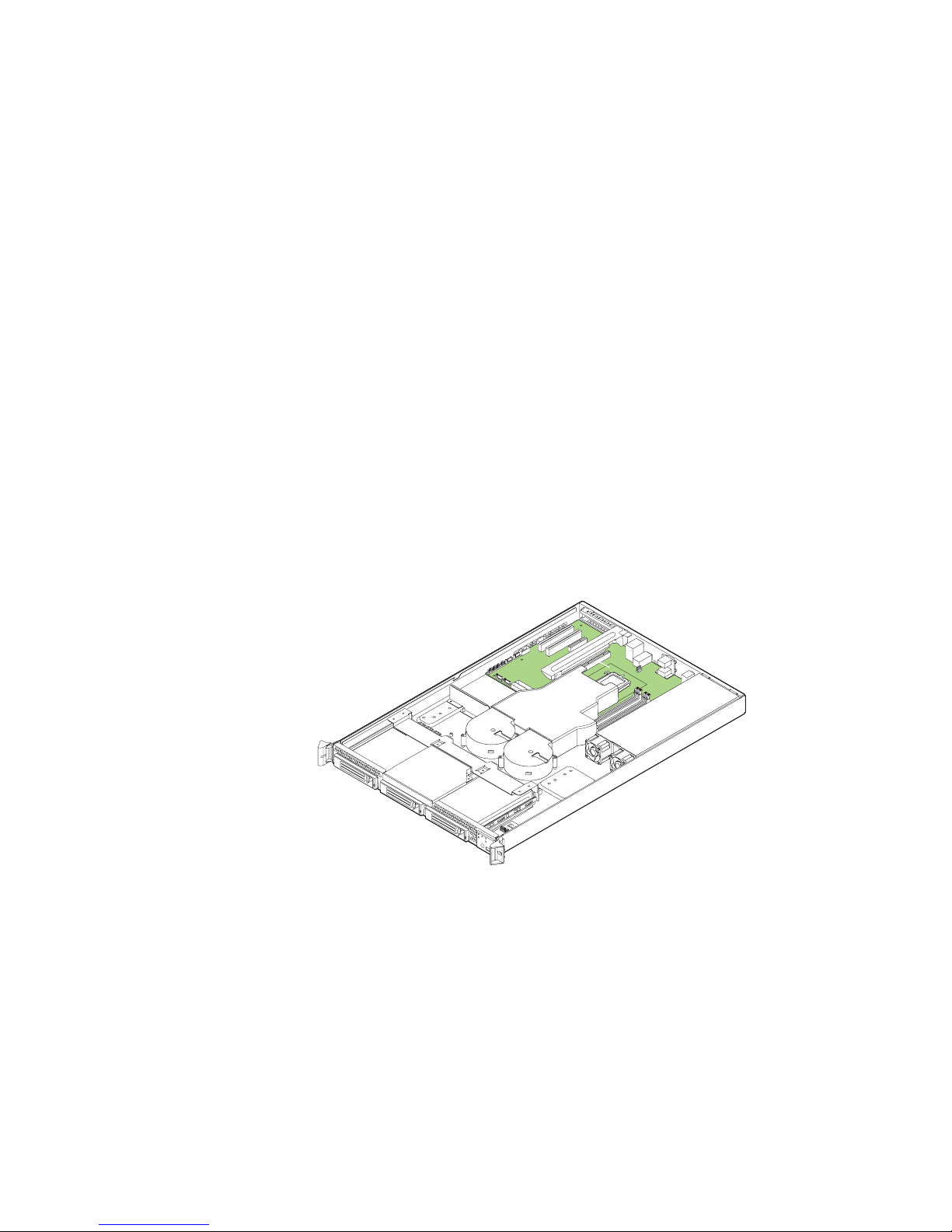
Installing and Removing a Hot-Swap SATA Drive
(SR1530HAHLX)
Up to three hot swappable SA TA drives can be installed. The HDD0 drive bay is at the left
side of the chassis, The HDD1 drive bay is in the middle of the chassis, underneath the
optional optical drive. The HDD2 drive bay is at the right side of the chassis. The drives
do not need to be installed in order; HDD1 can be installed before HDD0.
Cautions: If you install less than three drives or devices, the empty drive bays must be occupied by
carriers with baffles to maintain proper system cooling.
Note: The server system does not support all hard drives. See “Server System References” on
page x for an Internet link to a list of supported hardware.
Installing a Hot-Swap SATA Drive (SR1530HAHLX)
1. Remove the front bezel if it is installed. For instructions, see “Removing the Front
Bezel”.
2. Locate the drive position you want to use. See Figure 38.
Intel® Server System SR1530AH / SR1530AHLX / SR1530HAHLX 47
HDD 0
HDD 1
HDD 2
AF001582
Figure 38. Locating Drive Positions (SR1530HAHLX)
Page 70

3. Open the latch at the front of the hard drive carrier. See letter "A" in the figure
below.
A
AF001583
Figure 39. Removing the Drive Carrier (SR1530HAHLX)
4. Pull out on the black lever and slide the carrier from the server system.
5. Remove the four screws that attach the plastic retention device or the previously
installed hard drive to the drive carrier. Two screws are at each side of the retention
device or the hard drive. Store the plastic retention device for future use. See letter
“A” in Figure 40.
6. Remove the hard drive from its wrapper and place it on an antistatic surface.
7. Set any jumpers and/or switches on the drive according to the drive manufacturer's
instructions.
8. With the drive circuit-side down, position the connector end of the drive so that it is
facing the rear of the drive carrier.
9. Align the holes in the drive to the holes in the drive carrier and attach it to the
carrier with the screws that were attached to the plastic retention device. See letter
“B” in Figure 40.
A
B
AF001584
Figure 40. Installing Drive into Drive Carrier (SR1530HAHLX)
48 Intel® Server System SR1530AH / SR1530AHLX / SR1530HAHLX
Page 71

10. With the black lever in the fully open position, slide the drive assembly into the
server system (see letter “A” in Figure 41). The green latch at the front of the drive
carrier must be to the right. Do not push on the black drive carrier lever until the
lever begins to close by itself.
11. When the black drive carrier lever begins to close by itself, push on it to lock the
drive assembly into place (see letter “B” in Figure 41).
A
B
AF001585
Figure 41. Install Drive Assemby into the Server System (SR1530HAHLX)
12. Install the server system cover. For instructions, see “Installing the Server System
Cover”.
13. (Optional) Install the front bezel. For instructions, see “Installing the Front Bezel”.
14. Plug all peripheral devices and the AC power cable(s) into the server.
Removing a Hot-Swap SATA Drive (SR1530HAHLX)
1. Remove the front bezel if it is installed. For instructions, see “Removing the Front
Bezel”.
2. Press in on the green latch at the front of the hard drive carrier.
3. Pull out on the black lever to slide the carrier from the server system.
4. Remove the four screws that attach the hard drive to the drive carrier. Lift the drive
from the carrier. Store the drive in an anti-static bag.
5. If you are not installing a new drive, place the plastic retention device into the drive
carrier, using the four screws you removed from the hard drive.
6. Insert the screws that held the drive in the carrier into the screw locations on the
carrier for future use.
7. With the black lever in the fully open position, slide the drive carrier into the server
system. The green latch must be to the right. Do not push on the black lever until
the lever begins to close by itself.
Intel® Server System SR1530AH / SR1530AHLX / SR1530HAHLX 49
Page 72

Note: For pr oper airflow, the hard drive carrier must be replaced in the server system, even if no
hard drive is installed in it.
8. When the black lever begins to close by itself, push on it to lock the drive carrier
into place.
9. Install the server system cover. For instructions, see “Installing the Server System
Cover”.
10. (Optional) Install the front bezel. For instructions, see “Installing the Front Bezel”.
11. Plug all peripheral devices and the AC power cable(s) into the server.
Installing or Removing a Slimline Optical Drive
(SR1530AH / SR1530AHLX)
Caution: The optical drive is NOT hot swappable. Before removing or replacing the optical drive,
you must first take the server out of service, turn off all peripheral devices connected to
the system, turn off the system by pressing the power button, and unplug the AC power
cord from the system or wall outlet.
Installing a Slimline Optical Drive
Notes:
• If you are replacing an optical drive, see “Removing a Slimline Optical Drive” on
page 54 for instructions first. Return to these steps when directed.
• The hardware necessary to install your optical drive was shipped to you in a bag
labeled “CD-ROM Assy”.
1. Observe the safety and ESD precautions at the beginning of this book. See “Safety
Information” on page iii.
2. Power down the server and unplug all peripheral devices and the AC power cable.
3. Remove the server system cover. For instructions, see “Removing the Server
System Cover” on page 28.
4. Remove the bezel if it is installed. For instructions, see “Removing the Front
Bezel” on page 26.
5. Note the orientation of the PCI cooling fan that is located behind the optical drive
bay, then lift the fan from the mounting pegs. It is not necessary to disconnect the
fan cable. See letter “A” in Figure 42.
50 Intel® Server System SR1530AH / SR1530AHLX / SR1530HAHLX
Page 73

A
AF000679
Figure 42. Lifting PCI Cooling Fan from Mounting Pegs (SR1530AH/
SR1530AHLX)
6. First time installation only: Remove the knock-out by rocking it back and forth. See
letter “A” in the figure below. The knock-out cannot be reinstalled.
A
AF001172
Figure 43. Removing the Knock-out from the Sheet Metal Panel
7. Attach the interposer board to the rear of the CD-ROM or DVD-ROM drive, using
two screws, as shown by the following figure.
Intel® Server System SR1530AH / SR1530AHLX / SR1530HAHLX 51
Page 74

B
A
AF001186
Figure 44. Attaching the Interposer Board
8. Attach the optical drive to the brackets, using the four screws as shown by
Figure 45.
Figure 45. Attaching the Optical Drive to the Brackets
9. Slide the optical drive assembly in through the front of the chassis, as shown by
letter “A in Figure 46.
10. Reinstall the screw that you removed in step 6.
11. A daisy chain cable is used for the hard disk drives and the optical drive. Connect
the end connector on the daisy chain cable to the power connector on the optical
drive. See letter “C” in the figure below.
52 Intel® Server System SR1530AH / SR1530AHLX / SR1530HAHLX
AF000672
Page 75

12. Connect the data cable to the optical drive and to the IDE connector on the server
board. See letter “D” in the figure below.
D
B
A
A
B
C
C
C
D
D
AF000671
Figure 46. Installing the Optical Drive into the System
13. SR1530AH/SR1530AHLX: Insert the PCI cooling fan onto the mounting pegs that
are located behind the optical drive bay. The fan label should face the rear of the
system. See letter “A” in Figure 47.
Figure 47. Installing the PCI Cooling Fan (SR1530AH/SR1530AHLX)
14. Optional: Install the front bezel. For instructions, see “Installing the Front Bezel”
on page 27.
15. Install the server system cover. For instructions, see “Installing the Server System
Cover”.
16. Plug all peripheral devices and the AC power cable into the server.
Intel® Server System SR1530AH / SR1530AHLX / SR1530HAHLX 53
A
AF000680
Page 76

Removing a Slimline Optical Drive
1. Observe the safety and ESD precautions at the beginning of this book. See “Safety
Information” on page iii.
2. Power down the server and unplug all peripheral devices and the AC power cable.
3. Remove the server system cover. For instructions, see “Removing the Server
System Cover” on page 28.
4. Remove the bezel if it is installed. For instructions, see “Removing the Front
Bezel” on page 26.
5. SR1530AH/SR1530AHLX: Note the orientation of the PCI cooling fan that is
located behind the optical drive bay, then lift the fan from the mounting pegs. It is
not necessary to disconnect the fan cable. See letter “A” in Figure 48.
A
AF001208
Figure 48. Lifting PCI Cooling Fan from Mounting Pegs (SR1530AH/
SR1530AHLX)
6. Disconnect the optical drive power and data cables. See letters “A” and “B” in
Figure 49.
7. Remove the screw that holds the optical drive bracket to the server chassis. See
letter “C” in the figure below. Save this screw. You will reinstall it later.
8. Slide the optical drive out through the front of the system. See letter “D” in the
figure.
54 Intel® Server System SR1530AH / SR1530AHLX / SR1530HAHLX
Page 77

C
D
B
A
AF000670
Figure 49. Removing the Optical Drive from the Server System
9. Remove the four screws that hold the optical drive to the brackets as shown by
Figure 45. Save these screws for future use.
Figure 50. Attaching the Optical Drive Bracket to the Brackets
10. Remove the two screws at the back of the CD-ROM or DVD-ROM drive to detach
the interposer board. See letter “A” in the figure below.
11. Carefully pull the interposer board from the drive, detaching the interposer board
connector from the drive. See letter “B” in the figure below.
Intel® Server System SR1530AH / SR1530AHLX / SR1530HAHLX 55
AF000672
Page 78

B
A
AF001203
Figure 51. Removing the Interposer Board from the Optical Drive
12. If you are installing a replacement optical drive, skip the rest of these steps and
instead continue with "Installing a Slimline Optical Drive", step 8 on page 52.
13. Store the brackets and interposer board for future use.
14. SR1530AH/SR1530AHLX: Insert the PCI cooling fan onto the mounting pegs that
are located behind the optical drive bay. The fan label should face the rear of the
system.
A
B
Figure 52. Installing the PCI Cooling Fan (SR1530AH/SR1530AHLX)
15. Optional: Install the front bezel. For instructions, see “Installing the Front Bezel”
on page 27.
16. Install the server system cover. For instructions, see “Installing the Server System
Cover”.
56 Intel® Server System SR1530AH / SR1530AHLX / SR1530HAHLX
AF001209
Page 79
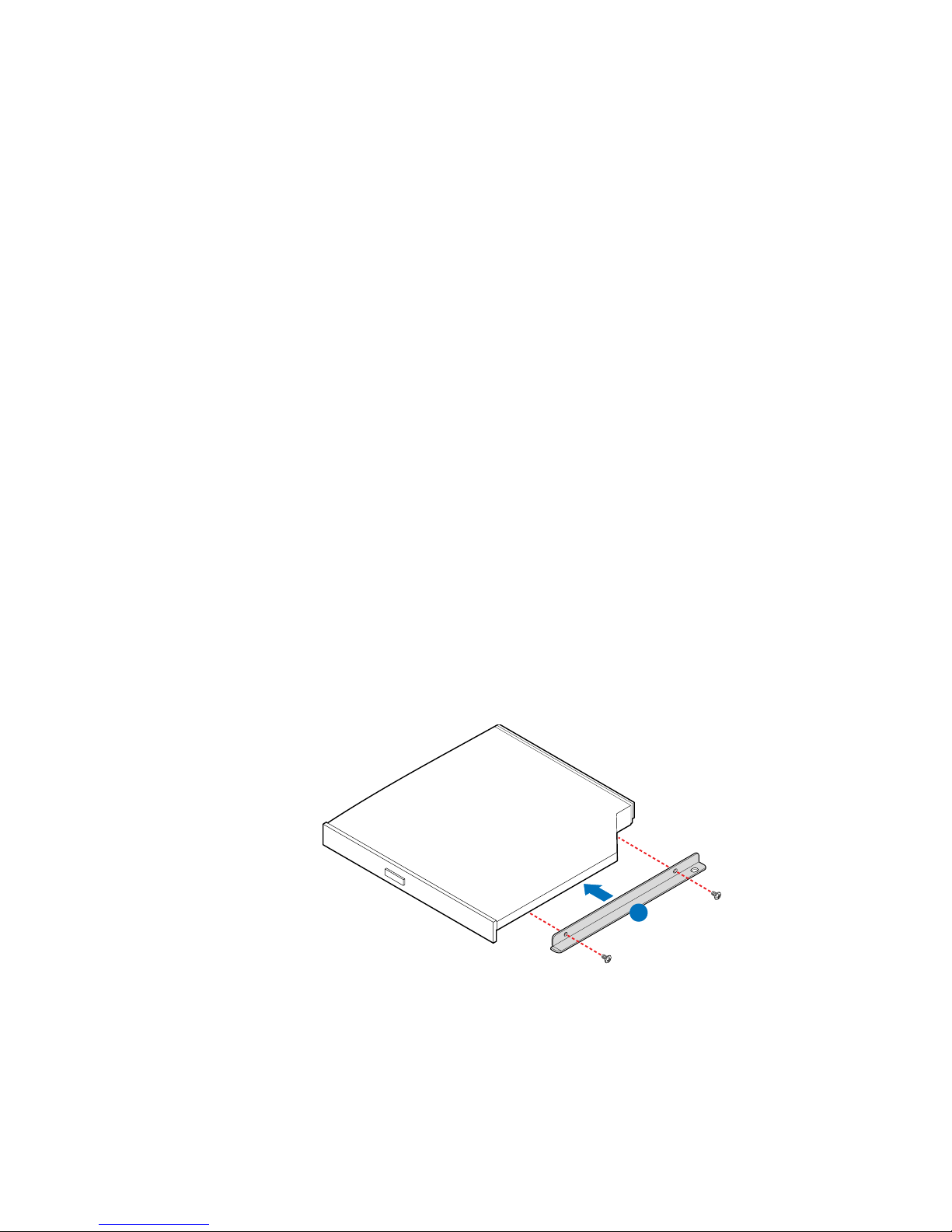
Installing or Removing a Slimline Optical Drive
(SR1530HAHLX)
Caution: The optical drive is NOT hot swappable. Before removing or replacing the optical drive,
you must first take the server out of service, turn off all peripheral devices connected to
the system, turn off the system by pressing the power button, and unplug the AC power
cord from the system or wall outlet.
Installing a Slimline Optical Drive (SR1530HAHLX)
Note: The hardware necessary to install your optical drive was shipped to you in a bag labeled
“CD-ROM Assy”.
1. Observe the safety and ESD precautions at the beginning of this book. See “Safety
Information” on page iii.
2. Power down the server and unplug all peripheral devices and the AC power cable.
3. Remove the server system cover. For instructions, see “Removing the Server
System Cover” on page 28.
4. Remove the bezel if it is installed. For instructions, see “Removing the Front
Bezel” on page 26.
5. First time installation only: Remove the peripheral knock-out by rocking it back
and forth.
6. Attach the optical drive attachment bracket as shown in the figure below.
A
AF001643
Figure 53. Attaching the Optical Drive to the Attachment Bracket
7. Slide the optical drive assembly in through the front of the chassis (see letter “A” in
the figure below).
Intel® Server System SR1530AH / SR1530AHLX / SR1530HAHLX 57
Page 80

8. Install the screws to lock the drive in place (see letters “B” and “C” in the figure
below).
B
C
A
AF001636
Figure 54. Installing the Optical Drive into the System
9. Optional: Install the front bezel. For instructions, see “Installing the Front Bezel”
on page 27.
10. Install the server system cover. For instructions, see “Installing the Server System
Cover”.
Removing a Slimline Optical Drive (SR1530HAHLX)
1. Observe the safety and ESD precautions at the beginning of this book. See “Safety
Information” on page iii.
2. Power down the server and unplug all peripheral devices and the AC power cable.
3. Remove the server system cover. For instructions, see “Removing the Server
System Cover” on page 28.
4. Remove the bezel if it is installed. For instructions, see “Removing the Front
Bezel” on page 26.
5. Remove the screws holding the drive in place (see letters “A” and “B” in the figure
below) and slide the optical drive assembly out through the front of the chassis (see
letter “C” in the figure below).
58 Intel® Server System SR1530AH / SR1530AHLX / SR1530HAHLX
Page 81

A
B
C
AF001635
Figure 55. Removing the Optical Drive from the System
6. Remove the optical drive attachment bracket as shown in the figure below.
A
AF001644
Figure 56. Removing the Optical Drive from the Attachment Bracket
7.
8. Optional: Install the front bezel. For instructions, see “Installing the Front Bezel”
on page 27.
9. Install the server system cover. For instructions, see “Installing the Server System
Cover”.
Intel® Server System SR1530AH / SR1530AHLX / SR1530HAHLX 59
Page 82

Installing and Removing the PCI Riser Assembly
Caution: The PCI riser assembly is NOT hot swappable. Before removing or replacing the PCI
riser assembly, you must first take the server out of service, turn off all peripheral devices
connected to the system, turn off the system by pressing the power button, and unplug the
AC power cord from the system or wall outlet.
Removing the PCI Riser Assembly
To remove the PCI riser assembly, use the following instructions.
1. Observe the safety and ESD precautions at the beginning of this book. See “Safety
Information” on page iii.
2. Power down the server and unplug all peripheral devices and the AC power cable.
3. Remove the server system cover. For instructions, see “Removing the Server
System Cover” on page 28.
4. Disconnect any cables attached to any add-in cards.
5. Lift riser assembly up to remove it. Use caution to gently easy the riser card from
the add-in card slot so you do not damage the slot or the riser card. See Figure 57.
Figure 57. Removing PCI Riser Assembly from the Server System
6. If you need to add or replace a PCI riser connector, see “Installing or Replacing a
PCI Riser Card” on page 62.
60 Intel® Server System SR1530AH / SR1530AHLX / SR1530HAHLX
AF000673
Page 83
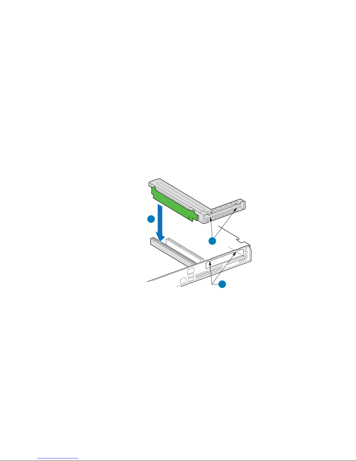
7. If you need to add or replace a PCI add-in card, see “Installing and Removing a PCI
Add-in Card” on page 64.
8. If you removed the PCI riser assembly for another procedure, continue with that
procedure.
Installing the PCI Riser Assembly
Note: For clarity, the figure in this series of instructions does not show an attached add-in card.
If you are installing an add-in card, do so before installing the PCI riser assembly into
your server system.
1. Lower the riser assembly into place over the add-in card slot. See letter “A” in the
following figure.
2. Align the three hooks in the riser assembly with the matching slots at the back of
the server system. See letter “B” in the figure.
A
B
C
AF000676
Figure 58. Installing PCI Riser Assembly into the Server System
3. Press down uniformly until the two hooks on the rear of the PCI riser assembly
engage the server system back panel slots. The riser cards will seat into the
matching sockets on the server board.
4. Connect any cables to add-in cards that require them. See your add-in card
documentation for information and add-in card requirements.
5. Install the server system cover. For instructions, see “Installing the Server System
Cover”.
Intel® Server System SR1530AH / SR1530AHLX / SR1530HAHLX 61
Page 84

Installing or Replacing a PCI Riser Card
Caution: The PCI riser card is NOT hot swappable. Before removing or replacing the PCI riser
card, you must first take the server out of service, turn off all peripheral devices connected
to the system, turn off the system by pressing the power button, and unplug the AC power
cord from the system or wall outlet.
You have the option to install one of two PCI riser cards into your server system:
• A full-height PCI Express* riser with one PCI Express x8 slot
• A full-height PCI-X* riser with one PCI-X slot
Note: To eliminate the possibility of installing the replacement connector on the wrong side of
the PCI riser assembly, replace one connector at a time.
Removing a PCI Riser Card
1. Observe the safety and ESD precautions at the beginning of this book. See “Safety
Information” on page iii.
2. Power down the server and unplug all peripheral devices and the AC power cable.
3. Remove the server system cover. For instructions, see “Removing the Server
System Cover” on page 28.
4. Disconnect any cables attached to any add-in cards.
5. Remove the PCI riser assembly. For instructions, see “Removing the PCI Riser
Assembly” on page 60.
6. Remove any add-in cards from the PCI riser connector. For instructions, see
“Removing a PCI Add-in Card” on page 65.
7. Remove the two screws that attach the riser card to the riser assembly. See the
following figure. Save these screws to be used later.
AF001061
Figure 59. Removing Riser Card from Riser Assembly
62 Intel® Server System SR1530AH / SR1530AHLX / SR1530HAHLX
Page 85

8. Install the replacement riser connector, if desired. For instructions, see “Installing a
PCI Riser Card” on page 63.
9. Install the PCI riser assembly into the server system. For instructions, see
“Installing the PCI Riser Assembly” on page 61.
10. Install the server system cover. For instructions, see “Installing the Server System
Cover”.
11. Plug all peripheral devices and the AC power cable into the server.
Installing a PCI Riser Card
1. Observe the safety and ESD precautions at the beginning of this book. See “Safety
Information” on page iii.
2. Power down the server and unplug all peripheral devices and the AC power cable.
3. Remove the server system cover. For instructions, see “Removing the Server
System Cover”.
4. Disconnect any cables attached to any add-in cards.
5. Remove the PCI riser assembly. For instructions, see “Removing the PCI Riser
Assembly” on page 60.
6. Remove any add-in cards from the PCI riser connector. For instructions, see
“Removing a PCI Add-in Card” on page 65.
7. Use two screws to attach the riser card to the riser assembly. See the figure below.
AF001060
Figure 60. Installing Riser Card onto Riser Assembly
8. Install an PCI add-in card if desired. For instructions, see “Installing a PCI Add-in
Card” on page 64.
9. Install the PCI riser assembly into the server system. For instructions, see
“Installing the PCI Riser Assembly” on page 61.
10. Connect any cables to add-in cards that require them. See your add-in card
documentation for information and add-in card requirements.
Intel® Server System SR1530AH / SR1530AHLX / SR1530HAHLX 63
Page 86

11. Re-install the processor air duct. For instructions, see “Installing the Processor Air
Duct” on page 33.
12. Install the server system cover. For instructions, see “Installing the Server System
Cover”.
13. Plug all peripheral devices and the AC power cable into the server.
Installing and Removing a PCI Add-in Card
Caution: The add-in cards are NOT hot swappable. Before removing or replacing an add-in card,
you must first take the server out of service, turn off all peripheral devices connected to
the system, turn off the system by pressing the power button, and unplug the AC power
cord from the system or wall outlet.
Installing a PCI Add-in Card
1. Observe the safety and ESD precautions at the beginning of this book. See “Safety
Information” on page iii.
2. Power down the server and unplug all peripheral devices and the AC power cable.
3. Remove the server system cover. For instructions, see “Removing the Server
System Cover” on page 28.
4. Remove the PCI riser assembly. For instructions, see “Removing the PCI Riser
Assembly” on page 60.
64 Intel® Server System SR1530AH / SR1530AHLX / SR1530HAHLX
Page 87

5. Remove the screw at the rear of the riser assembly. See letter “A” in Figure 61.
Save this screw. You will reinstall it later.
6. If a filler panel is installed over the opening at the rear of the riser assembly lift it
from the riser assembly. See letter “B” in the figure. Save the filler panel in case
you later need to remove the add-in card.
7. Insert the add-in card into the socket in the riser assembly . Push the add-in card into
place firmly until it seats in the riser card connector, but use caution so you do not
twist or bend the card. See letter “C” in the figure.
8. Re-install the screw you removed in step 5. See letter “A” in the figure.
B
C
A
AF000674
Figure 61. Installing an Add-In Card
9. Install the PCI riser assembly into the server system. For instructions, see
“Installing the PCI Riser Assembly” on page 61.
10. Install the server system cover. For instructions, see “Installing the Server System
Cover”.
11. Plug all peripheral devices and the AC power cable into the server.
Removing a PCI Add-in Card
1. Observe the safety and ESD precautions at the beginning of this book. See “Safety
Information” on page iii.
2. Power down the server and unplug all peripheral devices and the AC power cable.
3. Remove the server system cover. For instructions, see “Removing the Server
System Cover” on page 28.
4. Remove the PCI riser assembly. For instructions, see “Removing the PCI Riser
Assembly” on page 60.
Intel® Server System SR1530AH / SR1530AHLX / SR1530HAHLX 65
Page 88

5. Remove the screw at the rear of the riser assembly. See letter “A” in Figure 62.
Save this screw. You will use it later.
6. Pull the add-in card from the socket in the riser assembly. You may need to wriggle
the card from front to back to remove it, but use caution so you do not twist or bend
the card. See letter “B” in the figure.
7. Install a filler panel over the opening at the rear of the riser assembly. See letter “C”
in the figure.
8. Re-install the screw you removed in step 5. See letter “A” in the figure.
C
B
A
Figure 62. Removing a Full Height Add-In Card
Note: Make sure that all empty add-in card slots have filler panels installed.
AF000675
9. Install the PCI riser assembly into the server system. For instructions, see
“Installing the PCI Riser Assembly” on page 61.
10. Install the processor air duct. For instructions, see “Installing the Processor Air
Duct” on page 33.
11. Install the server system cover. For instructions, see “Installing the Server System
Cover”.
12. Plug all peripheral devices and the AC power cable into the server.
66 Intel® Server System SR1530AH / SR1530AHLX / SR1530HAHLX
Page 89

Replacing the Server Board
Removing the Server Board
1. Observe the safety and ESD precautions at the beginning of this book. See “Safety
Information” on page iii.
2. Power down the server and unplug all peripheral devices and the AC power cable.
3. Remove the server system cover. For instructions, see “Removing the Server
System Cover” on page 28.
4. Remove the processor air duct. For instructions, see “Removing the Processor Air
Duct” on page 31.
5. Remove the PCI riser assembly. For instructions, see “Removing the PCI Riser
Assembly” on page 60.
6. Detach all cables connected to the server board.
7. Remove the heat sink and the processor. For instructions, see “Removing the Heat
Sink and Processor” on page 37.
8. Remove the DIMMs. For instructions, see “Removing DIMMs” on page 36.
Intel® Server System SR1530AH / SR1530AHLX / SR1530HAHLX 67
Page 90
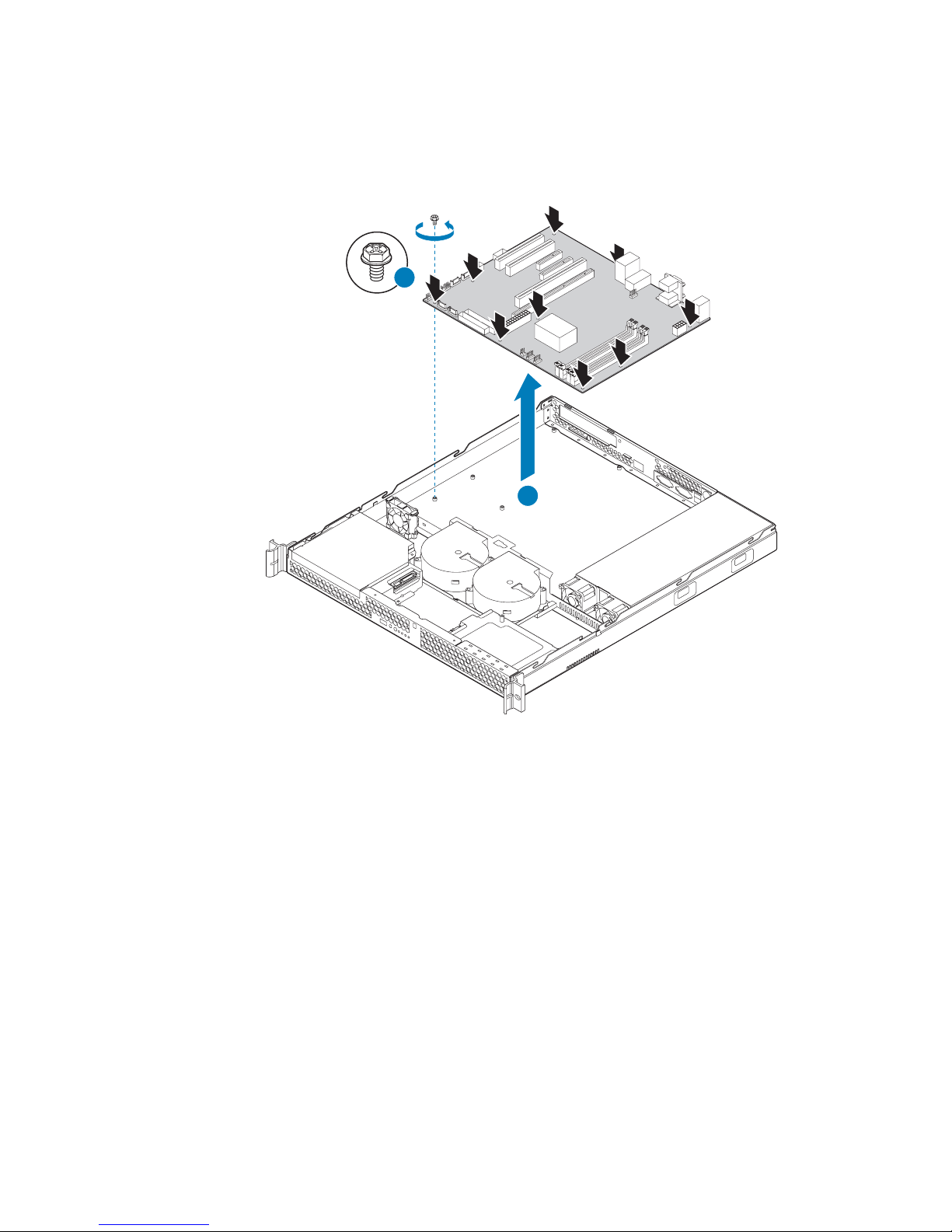
9. Remove the nine screws from the server board (see letter “A”) and lift the server
board from the server system (see letter “B”).
A
B
AF000677
Figure 63. Removing the Server Board
10. Replace the server board. For instructions, see “Installing the Server Board” on
page 69.
11. Install the processor. For instructions, see “Installing the Processor” on page 38.
12. Install the DIMMs. For instructions, see “Installing DIMMs” on page 34.
13. Install the PCI riser assembly. For instructions, see “Installing the PCI Riser
Assembly” on page 61.
14. Reconnect all cables to the server board. For a full cabling diagram, see Figure 88
on page 96
15. Install the processor air duct. For instructions, see “Installing the Processor Air
Duct” on page 33.
16. Install the server system cover. For instructions, see “Installing the Server System
Cover”.
17. Plug all peripheral devices and the AC power cable into the server.
68 Intel® Server System SR1530AH / SR1530AHLX / SR1530HAHLX
Page 91

Installing the Server Board
1. Observe the safety and ESD precautions at the beginning of this book. See “Safety
Information” on page iii.
2. Power down the server and unplug all peripheral devices and the AC power cable.
3. Remove the server system cover. For instructions, see “Removing the Server
System Cover” on page 28.
4. Remove the processor air duct. For instructions, see “Removing the Processor Air
Duct” on page 31.
5. Remove the PCI riser assembly. For instructions, see “Removing the PCI Riser
Assembly” on page 60.
6. Place the server board into the server system as shown by letter “A” in the figure
below.
7. Attach the server board with nine screws. See letter “B” in the figure.
B
Intel® Server System SR1530AH / SR1530AHLX / SR1530HAHLX 69
A
AF000678
Figure 64. Installing the Server Board
Page 92

8. Install the processor and the heat sink. For instructions, see “Installing the
Processor” on page 38.
9. Install the system memory. For instructions, see “Installing DIMMs” on page 34.
10. Connect the data cables. For data cable routing information, see “Cable Routing”
on page 95.
11. Connect the power cables. For power cable routing information, see “Cable
Routing” on page 95
12. Install the PCI riser assembly. For instructions, see “Installing the PCI Riser
Assembly” on page 61.
13. Install the processor air duct. For instructions, see “Installing the Processor Air
Duct” on page 33.
14. Install the server system cover. For instructions, see “Installing the Server System
Cover”.
15. Plug all peripheral devices and the AC power cable into the server.
Replacing the CMOS Battery
Caution: The CMOS battery is NOT hot swappable. Before remo ving or replacing the CMOS
battery, you must first take the server out of service, turn off all peripheral devices
connected to the system, turn off the system by pressing the power button, and unplug the
AC power cord from the system or wall outlet.
The lithium battery on the server board powers the RTC in the absence of power. When
the battery starts to weaken, it loses voltage, and the server settings stored in CMOS RAM
in the RTC (for example, the date and time) may be wrong. Contact your customer service
representative or dealer for a list of approved devices.
Warning: Danger of explosion if battery is incorrectly replaced. Replace only with the same or
equivalent type recommended by the equipment manufacturer. Discard used batteries
according to manufacturer's instructions.
Advarsel: Lithiumbatteri - Eksplosionsfare ved fejlagtig håndtering. Udskiftning må kun ske med
batteri af samme fabrikat og type. Levér det brugte batteri tilbage til leverandøren.
Advarsel: Lithiumbatteri - Eksplosjonsfare. Ved utskifting benyttes kun batteri som anbefalt av
apparatfabrikanten. Brukt batteri returneres apparatleverandøren.
Varning: Explosionsfara vid felaktigt batteribyte. Använd samma batterityp eller en ekvivalent typ
som rekommenderas av apparattillverkaren. Kassera använt batteri enligt fabrikantens
instruktion.
Varoitus: Paristo voi räjähtää, jos se on virheellisesti asennettu. Vaihda paristo ainoastaan
laitevalmistajan suosittelemaan tyyppiin. Hävitä käytetty paristo valmistajan ohjeiden
mukaisesti.
70 Intel® Server System SR1530AH / SR1530AHLX / SR1530HAHLX
Page 93
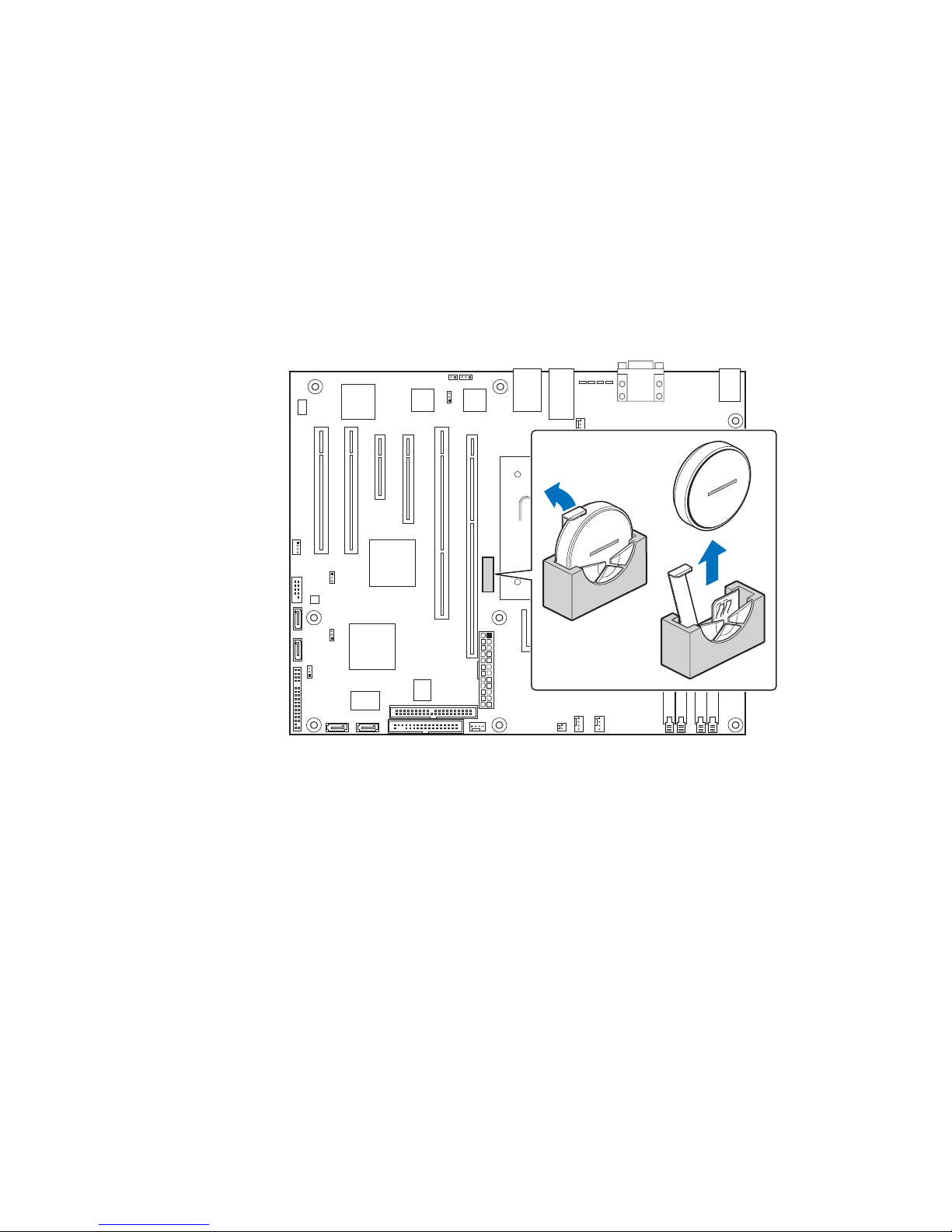
1. Observe the safety and ESD precautions at the beginning of this book. See “Safety
Information” on page iii.
2. Power down the server and unplug all peripheral devices and the AC power cable.
3. Remove the server system cover. For instructions, see “Removing the Server
System Cover” on page 28.
4. Remove the server's cover and locate the battery. See Figure 65.
5. Pull back gently on the metal tab at the top of the battery.
6. Remove the battery from its socket.
AF000524
Figure 65. Replacing the CMOS Battery
7. Dispose of the battery according to local ordinance.
8. Remove the new lithium battery from its package, and, being careful to observe the
correct polarity, insert it in the battery socket.
9. Close the chassis.
10. Run the BIOS Setup utility to restore the configuration settings.
Intel® Server System SR1530AH / SR1530AHLX / SR1530HAHLX 71
Page 94

Replacing the Power Supply (SR1530AH /
SR1530AHLX)
Caution: The power supply is NOT hot swappable. Befor e removing or replacing the power supply,
you must first take the server out of service, turn off all peripheral devices connected to
the system, turn off the system by pressing the power button, and unplug the AC power
cord from the system or wall outlet.
The power supply can be replaced if it fails or if one of the fans that is integrated into it
fails. To replace the power supply, use the following instructions.
1. Observe the safety and ESD precautions at the beginning of this book. See “Safety
Information” on page iii.
2. Power down the server and unplug all peripheral devices and the AC power cable.
3. Remove the server system cover. For instructions, see “Removing the Server
System Cover”.
4. Disconnect all power cables connected to the server board and peripherals. See
Figure 66:
— A: 2x4 power connector
— B: 2x12 main power connector
— C: Daisy-chain cable to:
✧ Optical drive power connector, if an optical drive is installed
✧ HDD0 power connector, if a hard drive is installed here
✧ HDD1 power connector, if a hard drive is installed here
72 Intel® Server System SR1530AH / SR1530AHLX / SR1530HAHLX
Page 95
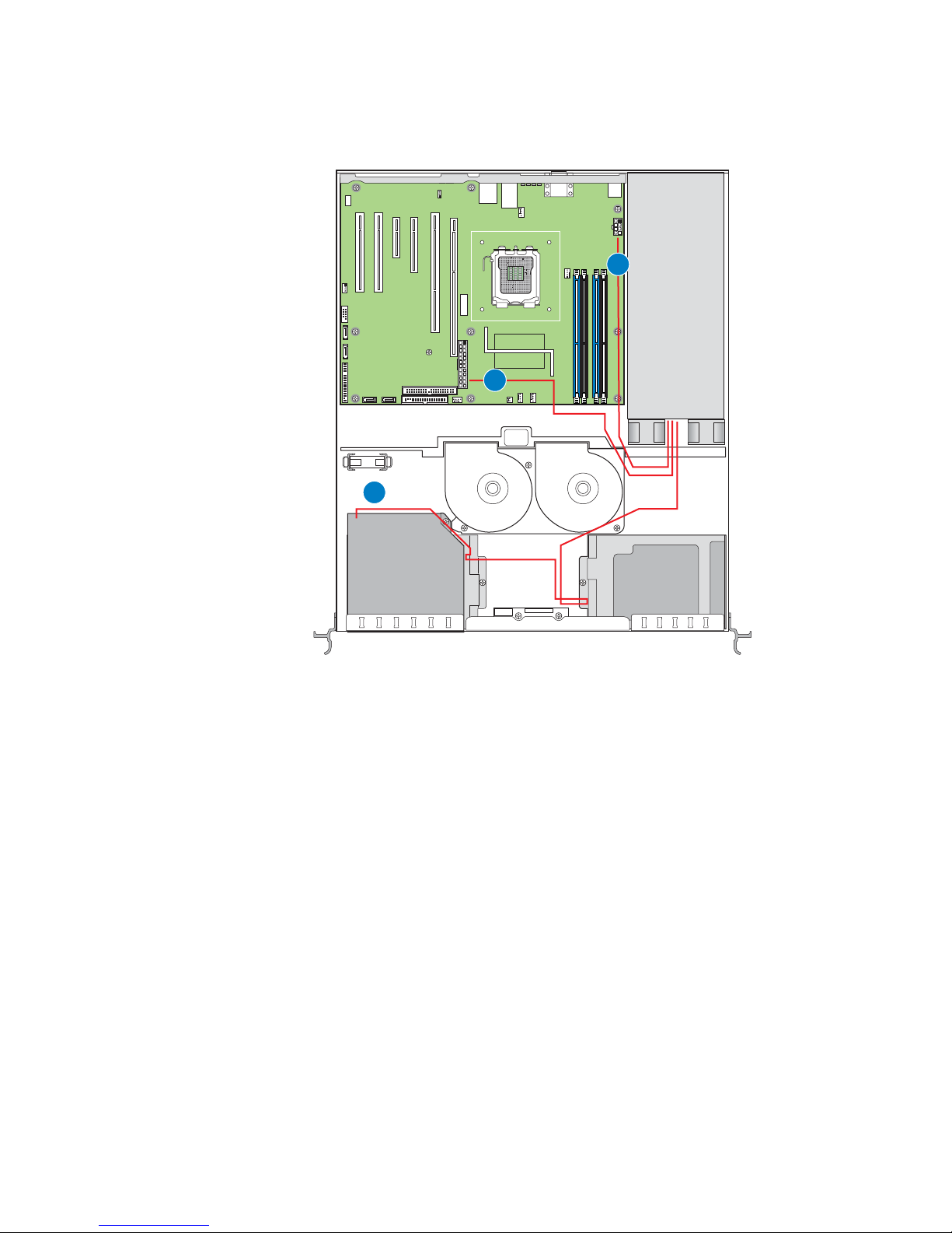
.
A
B
C
AF000969
Figure 66. Disconnecting Power Cables (SR1530AH / SR1530AHLX)
Intel® Server System SR1530AH / SR1530AHLX / SR1530HAHLX 73
Page 96

5. Remove the screw at the back of the server system, next to the AC power input.
Save this screw. You will re-insert it later. See letter “A” in the figure below.
6. Lift up slightly on the front of the power supply until it clears the foot at the bottom
of the chassis. See letter “B” in the figure.
7. Slide the power supply forward (see letter “C”) and then lift it from the chassis.
A
B
C
B
AF000965
Figure 67. Removing Power Supply from the Server System (SR1530AH /
SR1530AHLX)
74 Intel® Server System SR1530AH / SR1530AHLX / SR1530HAHLX
Page 97

8. Insert the replacement power supply at an angle into the server system, sliding the
power connector side in first to fit it through the cut-out area at the rear of the
system. See letter “A” in the figure below.
9. Set the front of the power supply down pushing the power supply back so it fits
behind the foot at the bottom of the chassis. See letter “B” in the figure.
10. Insert the screw you rem oved in step 5 to attach the power supply to the server
system. See letter “C”.
C
B
A
B
AF000966
Figure 68. Installing Power Supply Module into the Server System
(SR1530AH / SR1530AHLX)
Intel® Server System SR1530AH / SR1530AHLX / SR1530HAHLX 75
Page 98

11. Connect the power supply cables to the server board and peripherals. See Figure 68.
— A: 2x4 power connector
— B: 2x12 main power connector
— C: Daisy chain cable to:
✧ HDD1 power connector, if a hard drive is installed here. Use the connector on
cable that is closest to power supply
✧ HDD0 power connector, if a hard drive is installed here. Use the center
connector on the cable
✧ Optical drive power, if an optical drive is installed. Use the end connector on
the power supply
.
A
B
C
AF000969
Figure 69. Connecting Power Cables (SR1530AH / SR1530AHLX)
12. Install the server system cover. For instructions, see “Installing the Server System
Cover”.
13. Plug all peripheral devices and the AC power cable into the server.
76 Intel® Server System SR1530AH / SR1530AHLX / SR1530HAHLX
Page 99

Replacing the Power Supply (SR1530HAHLX)
Caution: The power supp ly is NOT ho t swappable. B efore removing or r eplacin g the power su pply,
you must first take the server out of service, turn off all peripheral devices connected to
the system, turn off the system by pressing the power button, and unplug the AC power
cord from the system or wall outlet.
The power supply can be replaced if it fails or if one of the fans that is integrated into it
fails. To replace the power supply, use the following instructions.
1. Observe the safety and ESD precautions at the beginning of this book. See “Safety
Information” on page iii.
2. Power down the server and unplug all peripheral devices and the AC power cable
(see letter “A” in the figure below).
3. Remove the server system cover. For instructions, see “Removing the Server
System Cover”.
4. Disconnect all power cables connected to the server board and peripherals.
5. Lift up slightly on the front of the power supply until it clears the foot at the bottom
of the chassis (see letter “B” in the figure below).
6. Slide the power supply forward (see letter “C” in the figure below) and then lift it
from the chassis.
A
C
B
AF001630
Figure 70. Removing Power Supply from the Server System (SR1530HAHLX)
Intel® Server System SR1530AH / SR1530AHLX / SR1530HAHLX 77
Page 100

7. Insert the replacement power supply at an angle into the server system, sliding the
power connector side in first to fit it through the cut-out area at the rear of the
system (see letter “A” in the figure below).
8. Set the front of the power supply down pushing the power supply back so it fits
behind the foot at the bottom of the chassis (see letter “B” in the figure below).
C
A
B
AF001631
Figure 71. Installing Power Supply Module into the Server System
(SR1530HAHLX)
9. Connect the power supply cables to the server board and peripherals.
10. Install the server system cover. For instructions, see “Installing the Server System
Cover”.
11. Plug all peripheral devices and the AC power cable into the server (see letter “C” in
the figure above).
78 Intel® Server System SR1530AH / SR1530AHLX / SR1530HAHLX
 Loading...