

Page 1

Intel® Server System SR1520ML
User’s Guide
A Guide for Technically Qualified Assemblers of Intel® Identified Subassemblies/
Products
Intel Order Number E17409-002
Intel® Server System SR1520ML User’s Guide i
Page 2

Disclaimer
Information in this document is provided in connection with Intel® products. No license, express or implied, by
estoppel or otherwise, to any intellectual property rights is granted by this document. Except as provided in Intel's
Terms and Conditions of Sale for such products, Intel assumes no liability whatsoever, and Intel disclaims any
express or implied warranty, relating to sale and/or use of Intel products including liability or warranties relating to
fitness for a particular purpose, merchantability, or infringement of any patent, copyright or other intellectual property
right. Intel products are not designed, intended or authorized for use in any medical, life saving, or life sustaining
applications or for any other application in which the failure of the Intel product could create a situation where
personal injury or death may occur. Intel may make changes to specifications and product descriptions at any time,
without notice.
Intel server boards contain a number of high-density VLSI and power delivery components that need adequate
airflow for cooling. Intel's own chassis are designed and tested to meet the intended thermal requirements of these
components when the fully integrated system is used together. It is the responsibility of the system integrator that
chooses not to use Intel developed server building blocks to consult vendor datasheets and operating parameters to
determine the amount of airflow required for their specific application and environmental conditions. Intel Corporation
can not be held responsible if components fail or the server board does not operate correctly when used outside any
of their published operating or non-operating limits.
Intel and Intel Xeon are trademarks or registered trademarks of Intel Corporation or its subsidiaries in the United
States and other countries.
* Other names and brands may be claimed as the property of others.
Copyright © 2007, Intel Corporation. All Rights Reserved
ii Intel® Server System SR1520ML User’s Guide
Page 3

Safety Information
Important Safety Instructions
Read all caution and safety statements in this document before performing any of the
instructions. See also Intel Server Boards and Server Chassis Safety Information on the
®
Server Deployment Toolkit 2.0 CD and/or at http://support.intel.com/support/
Intel
motherboards/server/sb/cs-010770.htm.
Wichtige Sicherheitshinweise
Lesen Sie zunächst sämtliche Warnund Sicherheitshinweise in diesem Dokument, bevor
Sie eine der Anweisungen ausführen. Beachten Sie hierzu auch die Sicherheitshinweise zu
Intel-Serverplatinen und Servergehäusen auf der Intel
oder unter http://support.intel.com/support/motherboards/server/sb/cs-010770.htm.
®
Server Deployment Toolkit 2.0 CD
Consignes de sécurité
Lisez attention toutes les consignes de sécurité et les mises en garde indiquées dans ce
document avant de suivre toute instruction. Consultez Intel Server Boards and Server
Chassis Safety Information sur le Intel
rendez-vous sur le site http://support.intel.com/support/motherboards/server/sb/cs-
010770.htm.
®
Server Deployment Toolkit 2.0 CD ou bien
Instrucciones de seguridad importantes
Lea todas las declaraciones de seguridad y precaución de este documento antes de realizar
cualquiera de las instrucciones. Vea Intel Server Boards and Server Chassis Safety
Information en el Intel
support.intel.com/support/motherboards/server/sb/cs-010770.htm.
®
Server Deployment Toolkit 2.0 CD y/o en http://
Intel® Server System SR1520ML User’s Guide iii
Page 4

Warnings
重要安全指导
在执行任何指令之前,请阅读本文档中的所有注意事项及安全声明。 和/或
http://support.intel.com/support/motherboards/server/sb/CS-010770.htm
上的 Intel
Server Boards and Server Chassis Safety Information(《Intel
服务器主板与服务器机箱安全信息》)。
Heed safety instructions: Before working with your server product, whether you are
using this guide or any other resource as a reference, pay close attention to the safety
instructions. You must adhere to the assembly instructions in this guide to ensure and
maintain compliance with existing product certifications and approvals. Use only the
described, regulated components specified in this guide. Use of other products /
components will void the UL listing and other regulatory approvals of the product and
will most likely result in noncompliance with product regulations in the region(s) in which
the product is sold.
System power on/off: The power button DOES NOT turn off the system AC power. To
remove power from system, you must unplug the AC power cord from the wall outlet.
Make sure the AC power cord is unplugged before you open the chassis, add, or remove
any components.
Hazardous conditions, devices and cables: Hazardous electrical conditions may be
present on power, telephone, and communication cables. Turn off the server and
disconnect the power cord, telecommunications systems, networks, and modems attached
to the server before opening it. Otherwise, personal injury or equipment damage can
result.
Electrostatic discharge (ESD) and ESD protection: ESD can damage disk drives,
boards, and other parts. We recommend that you perform all procedures in this chapter
only at an ESD workstation. If one is not available, provide some ESD protection by
wearing an antistatic wrist strap attached to chassis ground any unpainted metal surface on
your server when handling parts.
ESD and handling boards: Always handle boards carefully. They can be extremely
sensitive to ESD. Hold boards only by their edges. After removing a board from its
protective wrapper or from the server, place the board component side up on a grounded,
static free surface. Use a conductive foam pad if available but not the board wrapper. Do
not slide board over any surface.
iv Intel® Server System SR1520ML User’s Guide
Page 5

Installing or removing jumpers: A jumper is a small plastic encased conductor that slips
over two jumper pins. Some jumpers have a small tab on top that you can grip with your
fingertips or with a pair of fine needle nosed pliers. If your jumpers do not have such a tab,
take care when using needle nosed pliers to remove or install a jumper; grip the narrow
sides of the jumper with the pliers, never the wide sides. Gripping the wide sides can
damage the contacts inside the jumper, causing intermittent problems with the function
controlled by that jumper. Take care to grip with, but not squeeze, the pliers or other tool
you use to remove a jumper, or you may bend or break the pins on the board.
Intel® Server System SR1520ML User’s Guide v
Page 6

vi Intel® Server System SR1520ML User’s Guide
Page 7

Contents
Safety Information .....................................................................................................iii
Important Safety Instructions ................................................................................................ iii
Wichtige Sicherheitshinweise ............................................................................................... iii
Consignes de sécurité .......................................................................................................... iii
Instrucciones de seguridad importantes ............................................................................... iii
Warnings ............................................................................................................................... iv
Preface .....................................................................................................................xvii
About this Manual ...............................................................................................................xvii
Manual Organization ...........................................................................................................xvii
Product Contents ...............................................................................................................xviii
Server System References ................................................................................................. xix
Chapter 1: Server System Features ..........................................................................1
External Component Identification .........................................................................................3
System Front Panel .......................................................................................................3
System Rear ..................................................................................................................6
Peripheral Devices ........................................................................................................7
Internal Components .............................................................................................................8
Server Board Connectors ..............................................................................................8
Configuration Jumpers ................................................................................................10
SATA RAID Support ............................................................................................................11
Rack and Cabinet Mounting ................................................................................................11
Hardware Requirements ......................................................................................................11
Processor ....................................................................................................................12
Memory ........................................................................................................................12
Chapter 2: Hardware Installations and Upgrades .................................................13
Before You Begin .................................................................................................................13
Tools and Supplies Needed ........................................................................................13
System References .....................................................................................................13
Removing and Installing the Server Cover ..........................................................................14
Removing the Server System Cover ...........................................................................14
Installing the Server System Cover .............................................................................15
Installing and Removing a Hard Drive .................................................................................15
Installing a Hard Drive .................................................................................................16
Removing a Hard Drive ...............................................................................................18
Installing an Intel
Installing and Removing the PCI Riser Assembly ...............................................................21
Removing the PCI Riser Assembly .............................................................................21
Intel® Server System SR1520ML User’s Guide vii
®
Z-U130 Value Solid State Drive .............................................................20
Page 8

Installing the PCI Riser Assembly ............................................................................... 22
Removing and Installing the PCI Riser Card ....................................................................... 24
Removing the PCI Riser Card ..................................................................................... 24
Installing a PCI Riser Card .......................................................................................... 25
Installing and Removing a PCI Add-in Card ........................................................................ 26
Installing a PCI Add-in Card ........................................................................................ 26
Removing a PCI Add-in Card ...................................................................................... 27
Removing and Installing the Processor Air Duct ................................................................. 28
Removing the Processor Air Duct ............................................................................... 28
Installing the Processor Air Duct ................................................................................. 29
Installing and Removing Memory ........................................................................................ 29
Memory Population Rules ........................................................................................... 30
Installing DIMMs .......................................................................................................... 30
Removing DIMMs ........................................................................................................ 32
Replacing the Processor ..................................................................................................... 33
Removing the Heat Sink and Processor ..................................................................... 33
Installing the Processor ............................................................................................... 35
Installing the Heat Sink ............................................................................................... 36
Replacing the Power Supply ............................................................................................... 37
Replacing the Fans .............................................................................................................40
Replacing a Blower Fan .............................................................................................. 41
Replacing a Memory Cooling Fan ............................................................................... 44
Replacing a Server Board ................................................................................................... 46
Removing the Server Board ........................................................................................ 46
Installing the Server Board .......................................................................................... 48
Replacing the Front Panel Board ........................................................................................ 50
Replacing the CMOS Battery .............................................................................................. 52
Installing and Removing the Rack Handles ......................................................................... 55
Installing the Rack Handles ......................................................................................... 55
Removing the Rack Handles ....................................................................................... 56
Chapter 3: Server Utilities ........................................................................................57
Using the BIOS Setup Utility ............................................................................................... 57
Starting Setup ............................................................................................................. 57
If You Cannot Access Setup ....................................................................................... 57
Setup Menus ............................................................................................................... 57
Upgrading the BIOS ............................................................................................................ 59
Preparing for the Upgrade ........................................................................................... 59
Upgrading the BIOS .................................................................................................... 60
Recovering the BIOS ........................................................................................................... 60
Clearing the Password ........................................................................................................ 62
Performing an iBMC Force Update ..................................................................................... 64
Using the iBMC Boot Block Write Protect Jumper (J1A4) ................................................... 66
Appendix A: Technical Reference ...........................................................................67
viii Intel® Server System SR1520ML User’s Guide
Page 9

Cable Routing ......................................................................................................................67
Power Cable Routing ...................................................................................................68
Data Cable Routing .....................................................................................................69
600 W Power Supply Input Voltages ...................................................................................70
600 W Power Supply Output Voltages ................................................................................70
System Environmental Specifications ..................................................................................71
Appendix B: Installation/Assembly Safety Instructions .......................................73
English .................................................................................................................................73
Deutsch ................................................................................................................................75
Français ............................................................................................................................... 77
Español ................................................................................................................................79
Italiano .................................................................................................................................82
Appendix C: Troubleshooting .................................................................................85
Resetting the System ...........................................................................................................85
Problems following Initial System Installation ......................................................................86
First Steps Checklist ....................................................................................................86
Hardware Diagnostic Testing ...............................................................................................86
Verifying Proper Operation of Key System Lights .......................................................87
Confirming Loading of the Operating System ..............................................................87
Specific Problems and Corrective Actions ...........................................................................87
Power Light Does Not Light .........................................................................................88
No Characters Appear on Screen ...............................................................................88
Characters Are Distorted or Incorrect ..........................................................................89
System Cooling Fans Do Not Rotate Properly ............................................................89
Drive Activity Light Does Not Light ..............................................................................90
CD-ROM Drive or DVD-ROM Drive Activity Light Does Not Light ...............................90
Cannot Connect to a Server ........................................................................................90
Problems with Network ................................................................................................91
System Boots when Installing PCI Card ......................................................................91
Problems with Newly Installed Application Software ...................................................92
Problems with Application Software that Ran Correctly Earlier ...................................92
Devices are not Recognized under Device Manager (Microsoft* Windows* Operating
System) ............................................................................................................93
Hard Drive(s) are not Recognized ...............................................................................93
Bootable CD-ROM Disk Is Not Detected .....................................................................93
Appendix D: Getting Help ........................................................................................95
World Wide Web ..................................................................................................................95
Telephone ............................................................................................................................95
Appendix E: Warranty .............................................................................................. 99
Limited Warranty for Intel® Chassis Subassembly Products ..............................................99
Appendix F: Safety Information ............................................................................103
Intel® Server System SR1520ML User’s Guide ix
Page 10

English ............................................................................................................................... 103
Server Safety Information ......................................................................................... 103
Safety Warnings and Cautions .................................................................................. 103
Intended Application Uses ........................................................................................ 104
Site Selection ............................................................................................................ 104
Equipment Handling Practices .................................................................................. 104
Power and Electrical Warnings ................................................................................. 105
System Access Warnings ......................................................................................... 106
Rack Mount Warnings ............................................................................................... 106
Electrostatic Discharge (ESD) ................................................................................... 107
Other Hazards ........................................................................................................... 107
Deutsch ............................................................................................................................. 108
Sicherheitshinweise für den Server ........................................................................... 108
Sicherheitshinweise und Vorsichtsmaßnahmen ....................................................... 108
Zielbenutzer der Anwendung .................................................................................... 109
Standortauswahl ....................................................................................................... 109
Handhabung von Geräten ......................................................................................... 109
Warnungen zu Netzspannung und Elektrizität .......................................................... 110
Warnhinweise für den Systemzugang ....................................................................... 111
Warnhinweise für Racks ........................................................................................... 111
Elektrostatische Entladungen (ESD) ......................................................................... 112
Andere Gefahren ....................................................................................................... 112
Français ............................................................................................................................. 113
Consignes de securite sur le serveur ........................................................................ 113
Séurité: avertissements et mises en garde ............................................................... 113
Domaines d’utilisation prévus ................................................................................... 114
Sélection d’un emplacement ..................................................................................... 114
Pratiques de manipulation de l’équipement .............................................................. 115
Alimentation et avertissements en matiére d’électricité ............................................ 115
Avertissements sur le cordon d’alimentation ............................................................. 116
Avertissements sur l’accés au systéme .................................................................... 116
Avertissements sur le montage en rack .................................................................... 117
Décharges électrostatiques (ESD) ............................................................................ 118
Autres risques ........................................................................................................... 118
Périphériques laser ................................................................................................... 119
Español ............................................................................................................................. 119
Información de seguridad del servidor ...................................................................... 119
Advertencias y precauciones sobre seguridad ......................................................... 119
Aplicaciones y usos previstos ................................................................................... 120
Seleccién de la ubicación .......................................................................................... 120
Manipulacién del equipo ........................................................................................... 121
Advertencias de alimentacién y eléctricas ................................................................ 121
Advertencias sobre el cable de alimentación ............................................................ 121
Advertencias el acceso al sistema ............................................................................ 122
x Intel® Server System SR1520ML User’s Guide
Page 11

Advertencias sobre el montaje en bastidor ...............................................................124
Descarga electrostática (ESD) ..................................................................................124
Otros riesgos .............................................................................................................125
Appendix G: Regulatory and Compliance Information .......................................127
Product Regulatory Compliance ........................................................................................127
Product Safety Compliance .......................................................................................127
Product EMC Compliance - Class A Compliance ......................................................128
Certifications / Registrations / Declarations ...............................................................129
Product Regulatory Compliance Markings ................................................................129
Electromagnetic Compatibility Notices ..............................................................................132
FCC Verification Statement (USA) ............................................................................132
Industry Canada (ICES-003) .....................................................................................133
Europe (CE Declaration of Conformity) .....................................................................133
VCCI (Japan) .............................................................................................................133
BSMI (Taiwan) ...........................................................................................................133
Korean Compliance (RRL) ........................................................................................134
CNCA (CCC-China) ...................................................................................................134
Regulated Specified Components .............................................................................134
Product Ecology Requirements .........................................................................................135
End-of-Life / Product Recycling .........................................................................................136
Intel® Server System SR1520ML User’s Guide xi
Page 12

xii Intel® Server System SR1520ML User’s Guide
Page 13

List of Tables
Table 1. Server System References ...................................................................................... xix
Table 2. Feature Summary ........................................................................................................ 2
Table 3. NIC LED Descriptions .................................................................................................6
Table 4. Setup Menu Key Use ................................................................................................58
Table 5. Power Supply Output Capability ................................................................................70
Table 6. System Environmental Specifications .......................................................................71
Table 7. Resetting the System ................................................................................................85
Table 8. Product Regulatory Compliance Markings ..............................................................129
Intel® Server System SR1520ML User’s Guide xiii
Page 14

xiv Intel® Server System SR1520ML User’s Guide
Page 15

List of Figures
Figure 1. Intel® Server System SR1520ML............................................................................... 1
Figure 2. Front Controls and LEDs............................................................................................ 5
Figure 3. Back Panel Connectors.............................................................................................. 6
Figure 4. Optional Peripherals................................................................................................... 7
Figure 5. System Components.................................................................................................. 8
Figure 6. Server Board Connector Locations............................................................................ 9
Figure 7. Configuration Jumpers............................................................................................. 10
Figure 8. Removing the Server System Cover........................................................................ 14
Figure 9. Installing the Server System Cover.......................................................................... 15
Figure 10. Removing Drive Carrier from the Server System................................................... 16
Figure 11. Installing Drive Assembly....................................................................................... 18
Figure 12. Removing Drive Carrier.......................................................................................... 19
Figure 13. Installing the Drive Carrier...................................................................................... 20
Figure 14. Removing PCI Riser Assembly.............................................................................. 22
Figure 15. Installing PCI Riser Assembly into the Server System........................................... 23
Figure 16. Removing Riser Card from Riser Assembly........................................................... 24
Figure 17. Installing Riser Card onto Riser Assembly............................................................. 25
Figure 18. Installing an Add-In Card........................................................................................ 26
Figure 19. Removing an Add-In Card...................................................................................... 27
Figure 20. Removing the Processor Air Duct.......................................................................... 28
Figure 21. Installing the Processor Air Duct............................................................................ 29
Figure 22. Installing Memory DIMMs....................................................................................... 31
Figure 23. Removing Memory DIMMs..................................................................................... 32
Figure 24. Opening the Processor Socket Handle.................................................................. 34
Figure 25. Opening the Load Plate ......................................................................................... 34
Figure 26. Removing the Processor........................................................................................ 35
Figure 27. Installing the Processor.......................................................................................... 36
Figure 28. Installing the Heat Sink .......................................................................................... 37
Figure 29. Disconnecting Power Cables ................................................................................. 38
Figure 30. Removing Power Supply........................................................................................ 39
Figure 31. Installing Power Supply Module............................................................................. 40
Figure 32. Disconnecting Cables ............................................................................................ 41
Figure 33. Removing Bracket and Fans.................................................................................. 42
Figure 34. Removing Fan from Fan Bracket ........................................................................... 43
Figure 35. Disconnecting Memory Cooling Fan Cable............................................................ 44
Figure 36. Connecting Memory Cooling Fan Cable ................................................................ 45
Figure 37. Removing the Server Board................................................................................... 47
Figure 38. Installing the Server Board..................................................................................... 48
Figure 39. Connecting Cables to Server Board....................................................................... 49
Figure 40. Removing Front Panel Board................................................................................. 51
Figure 41. Installing Front Panel Board................................................................................... 52
Figure 42. Removing the CMOS Battery................................................................................. 54
Intel® Server System SR1520ML User’s Guide xv
Page 16

Figure 43. Installing the Rack Handle..................................................................................... 55
Figure 44. Removing the Rack Handle................................................................................... 56
Figure 45. BIOS Recovery Mode Jumper in Recovery Position ............................................. 61
Figure 46. Password Clear Jumper in Clear Password Position ............................................ 62
Figure 47. CMOS Clear Jumper in Clear CMOS Position ...................................................... 63
Figure 48. MiBMC Force Update Jumper in the Write Enable Position.................................. 65
Figure 49. Power Cable Routing............................................................................................. 68
Figure 50. Data Cable Routing ............................................................................................... 69
xvi Intel® Server System SR1520ML User’s Guide
Page 17

Preface
About this Manual
Thank you for purchasing and using the Intel® Server System SR1520ML.
This manual is written for system technicians who are responsible for troubleshooting,
upgrading, and repairing this server system. This document provides reference
information, feature information, and step by step instructions on how to add and replace
components on the server system. For the latest version of this manual, see http://
support.intel.com/support/motherboards/server/
Manual Organization
Chapter 1 provides an overview of the server system. In this chapter, you will find a list of
the server system features, illustrations of the product, and product diagrams to help you
identify components and their locations.
X38ML/.
Chapter 2 provides instructions on adding and replacing components. Use this chapter for
step-by-step instructions and diagrams for installing or replacing components such as the
fans, power supply, drives, and other components.
Chapter 3 provides instructions on using the utilities that are shipped with the board or
that may be required to update the system. This includes how to navigate through the
BIOS Setup screens, how to perform a BIOS update, and how to reset the password or
CMOS. Information about the specific BIOS settings and screens is available in the
Technical Product Specifications for the server board and chassis. See Table 1 on page xix
for a link to the Technical Product Specifications.
At the back of this manual, you will find technical specifications, troubleshooting tips,
regulatory information, complete safety information, “getting help” information, and the
warranty.
Intel® Server System SR1520ML User’s Guide xvii
Page 18

Product Contents
You r In te l® Server System SR1520ML ships with the following items.
• Two Intel
• One 600-watt power supply module, installed in the server chassis
• One power cable to connect to AC power (North America only)
• Four cooling fans, with attached cables, installed in the server system:
— Two memory cooling fans
— Two system blower fans
• Two passive heat sinks, in the server system product box
• Two hard drive brackets, in the server system product box
• Two PCI Express* x16 risers, installed in the server system
• Two processor / memory air ducts
• Rack handles, in the server system product box
• One front control panel board with front panel controls for two server boards,
installed in the server system
• One basic slide rail kit, in a separate box
®
Server Boards X38ML installed in the server chassis
• Cables:
— Two SATA cables, installed in the server system
— Two front panel / Z-U130 USB Y-cables, installed in the server system
— One front panel Y-cable, installed in the server system
• Intel
• Intel
®
Server Deployment Toolkit 2.0 CD that contains documentation, drivers, and
utilities
®
System Management Software 2.0 CD set. A two-CD set
xviii Intel® Server System SR1520ML User’s Guide
Page 19
Server System References
If you need more information about this product or information about the accessories that
can be used with this server chassis, use the following resources.
Table 1. Server System References
For this Information or
Software
Technical information
about the server chassis,
including sub-system
overviews and
mechanical drawings
Technical information
about the server board,
including board layout,
connector pin-outs, timing
information, mechanical
drawings and LED
information
Technical information
about the server system,
including connector pinouts, timing information,
mechanical drawings and
LED information
If you just received this
product and need to
install it
Accessories or other Intel
server products
Use this Document or Software
Intel® Server System SR1520MLTechnical Product Specification
At http://support.intel.com/support/motherboards/server/X38ML/
®
Intel
Server Board X38ML Technical Product Specification
At http://support.intel.com/support/motherboards/server/X38ML
®
Intel
Server System SR1520ML Technical Product Specification
At http://support.intel.com/support/motherboards/server/X38ML/
®
Intel
Server System SR1520ML Quick Start User's Guide
In the product box
Spares and Configuration Guide
Available from your Intel field representative or on the Server
Configurator Tool at http://indigo.intel.com/serverconfiguratortool/
default.aspx
Hardware (peripheral
boards, adapter cards)
and operating systems
that have been tested
with this product
Processor and DIMMs
that have been tested
with this produc
For drivers Search for the word “driver” (for an extensive list of available
For firmware and BIOS
updates, or for BIOS
recovery
Intel® Server System SR1520ML User’s Guide xix
Tested Hardware and Operating Systems List
At http://support.intel.com/support/motherboards/server/X38ML/
See http://support.intel.com/support/motherboards/server/X38ML/
drivers)
Search for “operating system driver” (for operating system drivers)
Firmware Updates
Page 20
Table 1. Server System References
For this Information or
Software
For software to manage
your Intel® server
To make sure your
system falls within the
allowed power budget
For diagnostics test
software
Use this Document or Software
®
Intel
System Management Software Software 2.0
At http://support.intel.com/support/motherboards/server/X38ML/
Search for the phrase “Power Budget Tool”
At http://support.intel.com/support/motherboards/server/X38ML/
Search for the word “Diagnostics”
xx Intel® Server System SR1520ML User’s Guide
Page 21
1 Server System Features
This chapter briefly describes the main features of the server system. It provides product
illustrations, a list of the server system features, and diagrams that show the location of
important components and connections.
Figure 1. Intel
The Intel
installed in it. Each server board operates as a fully functioning server system with it’s
own control panel, BIOS setup configuration, processor, memory, drives, add-in card,
keyboard/mouse, and video monitor. These items are not shared by the two server boards.
The two server boards share the chassis and power supply.
Since the server boards function independently, the processor and DIMM rules apply to
each board independently. The two server boards do not need to use identical processors
or DIMMs.
Intel® Server System SR1520ML User’s Guide 1
®
Server System SR1520ML ships with two Intel® Server Boards X38ML
®
Server System SR1520ML
Page 22
Table 2 summarizes the features of the server system.
Table 2. Feature Summary
Feature Description
Dimensions
• 1.67 inches high (42.42 mm)
• 16.93 inches wide (430.02 mm)
• 20 inches deep (508.00 mm)
Server board Intel
Processors Processor and Front Side Bus (FSB) support
®
Server Board X38ML. Two per system.
• The system supports one processor on each server board. For
supported Intel processors, see http://support.intel.com/
support/motherboards/server/X38ML
• Supports 800 / 1066 / 1333 MHz FSB
Memory
• Four DIMM sockets per server board supporting stacked
DDR2 667 / 800 MHz unbuffered ECC memory or non-ECC
memory
• Each server board has two memory channels with two DIMM
sockets per channel
• Support for up to 8 GB of total system memory on each server
board
Chipset Intel® X38 chipset on each server board, consisting of:
®
• Intel
• Intel
Peripheral Interfaces External connections on each server board:
X38 Memory Controller Hub (MCH)
®
I/O Controller Hub (ICH9R)
• DB9 Serial A port
• Two RJ45 NIC connectors for 10 / 100 / 1000 Mb connections
• Two USB 2.0 ports
• VGA header for video output
Internal connections on each server board:
• One USB port header, which supports two USB 2.0 ports
• One DH10 Serial B header
• Four Serial ATA connectors with embedded RAID 0/1/10
support
Video Each server board has an on-board video controller with 32 MB
DDR2 667 video memory
LAN Two Intel® 10 / 100 / 1000 82573E Gigabit Ethernet controllers on
each server board
Expansion capabilities One low-profile PCI Express* riser card for each server board.
Each supports one low-profile x1, x4, x8, or x16 adapter.
Hard drives
2 Intel® Server System SR1520ML User’s Guide
• Support for up to two 2.5-inch drives. SATA (3.0 Gb/s) support
• Support for two Intel
®
Z-U130 Value Solid State Drives
Page 23

Table 2. Feature Summary
Feature Description
Control panel Each server board has a control panel. Each control panel includes:
• One USB port
• Power / sleep button
• Reset button
• Power / sleep LED
• Status LED
• Hard drive activity LED
• NIC1 activity LED
• NIC2 activity LED
Power supply One 600-watt power supply module
Fans
• Two memory cooling fans. Each server board controls one fan.
• Two system blower fans. Each server board controls one fan.
USB
• Each server board has two USB ports on the back panel
• Each server board has one internal USB header, which
supports two USB ports
System management Intel® System Management 2.0 Software
External Component Identification
This section helps you identify the components of your server system. If you are near the
system, you can also use the quick reference label on the inside of the chassis cover to
assist in identifying components.
System Front Panel
Each server board has its own control panel at the front of the server system. Each control
panel includes the following buttons and LEDs.
Intel® Server System SR1520ML User’s Guide 3
Page 24
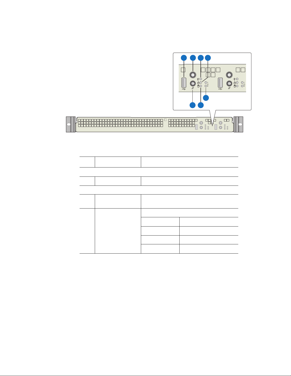
A B C D
G
Item Feature Description
Front Panel Connector
A USB connector 2.0 port, 4-pin connectors
Front Panel Buttons and LED Indicators
E
F
AF002495
B Server board power /
sleep button
C Power / sleep LED Green LED for system power status
Press to turn the system power on or off
LED State System Power State
Off Power off, S4 sleep
On Power on
Blink S1
4 Intel® Server System SR1520ML User’s Guide
Page 25
Item Feature Description
D System status / fault
LED
E LAN1, LAN 2 Status
LEDs
Green / amber LED for system status.
LED Statte System State
Off System not ready
Green on System ready, no alarm
Green blink System ready but degraded
by processor or DIMM error
Amber blink Non critical failure, such as
non-critical power or voltabe
error
Amber on Critical alarm. Critical power
module failure, critical fan
failure, power supply,
voltage or thermal fault
Green LEDs that show the status of each LAN
port
LED State LAN State
Off Idle
On LAN link / no access
Blinking Active
F Hard drive activity
LED
G System reset button Press to reset the system
Green LED that indicates hard drive activity
LED State Drive State
Green blink Drive is active
Off Drive is not active
Figure 2. Front Controls and LEDs
Intel® Server System SR1520ML User’s Guide 5
Page 26
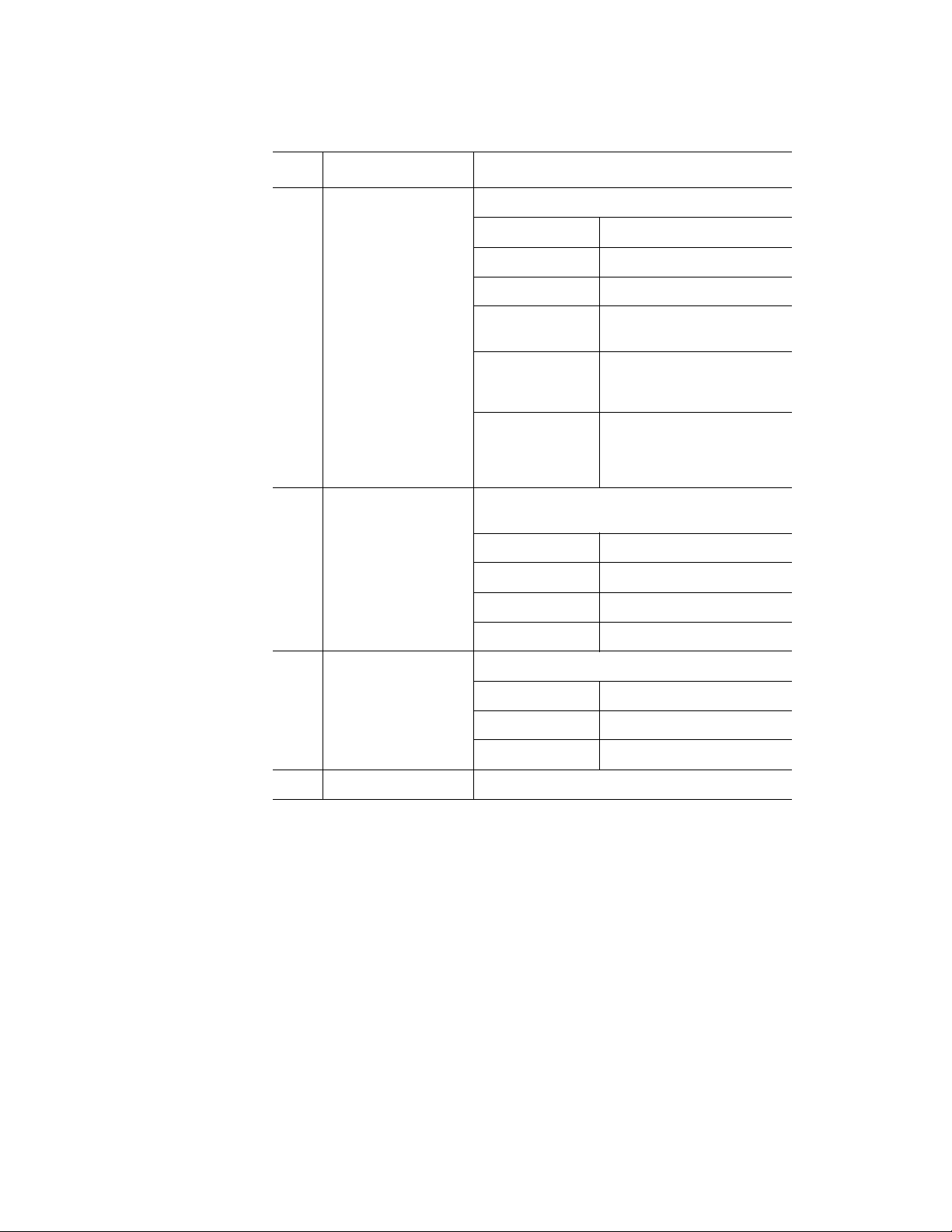
System Rear
Except for the shared AC power supply, each server board has its own back panel
connectors.
A
A. AC power connector (one per
system)
B. PCI Express* add-in card slot
location (one for each server board)
C. NIC 1 (10 / 100 / 1000 Mb) (one for
each server board)
D. Video connector (one for each server
board)
B B
E
D
Figure 3. Back Panel Connectors
C
D
G
F
E. Serial port (one for each server
board)
F. NIC 2 (10 / 100 / 1000 Mb) (one for
each server board)
G. USB ports 0-1 (one sets of two ports
for each server board)
E
C
G
F
AF002496
The LEDs at the right and left of each NIC provide the following information.
Table 3. NIC LED Descriptions
LED LED State Description
Left Off No network connection
Solid amber Network connection in place
Blinking amber Transmit/receive activity
Right Off 10 Mbps connection (if left LED is on or blinking)
Solid amber 100 Mbps connection
Solid green 1000 Mbps connection
6 Intel® Server System SR1520ML User’s Guide
Page 27
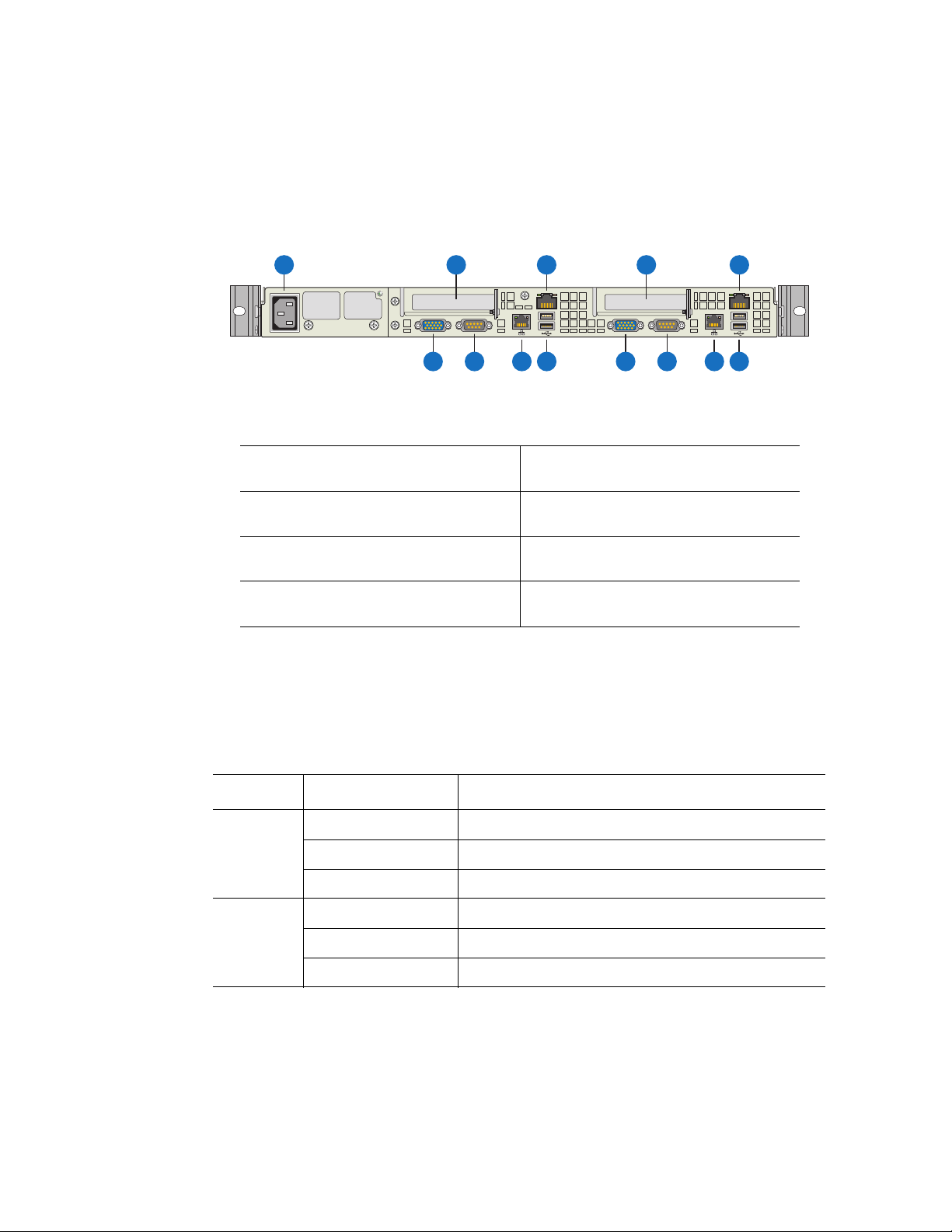
Peripheral Devices
The server system provides locations for installing up to two fixed 2.5-inch SATA hard
drives and up to two Intel
®
Z-U130 Value Solid State Drive (Intel® VSSD). Each server
board controls one of each of these drives. No optical or floppy drive bays are available,
but these devices are supported through an external USB connection. The drives must be
purchased separately. The following figure shows the available options.
B
.
A
AF002494
A. Two 2.5-inch hard drive bays, stacked on top of each other
B. Two Intel® Z-U130 Value Solid State Drive bays
Figure 4. Optional Peripherals
For instructions on installing a hard drive, see “Installing and Removing a Hard Drive” on
page 15.
®
For instructions on installing the Intel
titled Intel
®
Z-U130 Value Solid State Drive Mounting Kit Installation Guide for Intel®
Z-U130 Value Solid State Drive, see the document
Server Systems.
Note: Drives can consume up to 17 watts of power each. Drives must be specified to run at a
maximum ambient temperature of 45
®
Note: The Intel
Server System SR1520ML does not support all Serial ATA (SATA) hard drives.
o
C.
See “Server System References” on page xix for an Internet link to a list of supported
hardware.
Intel® Server System SR1520ML User’s Guide 7
Page 28
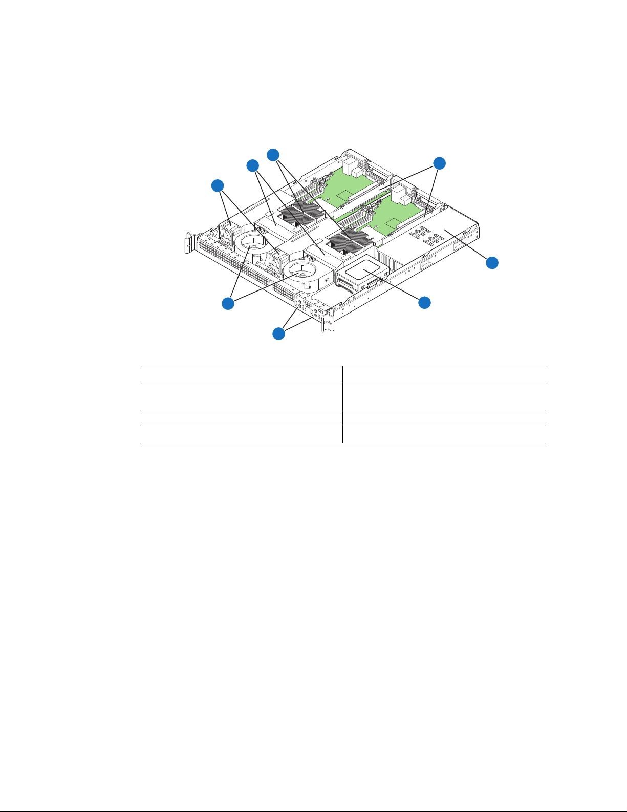
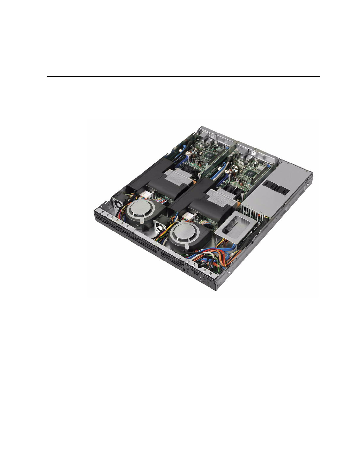
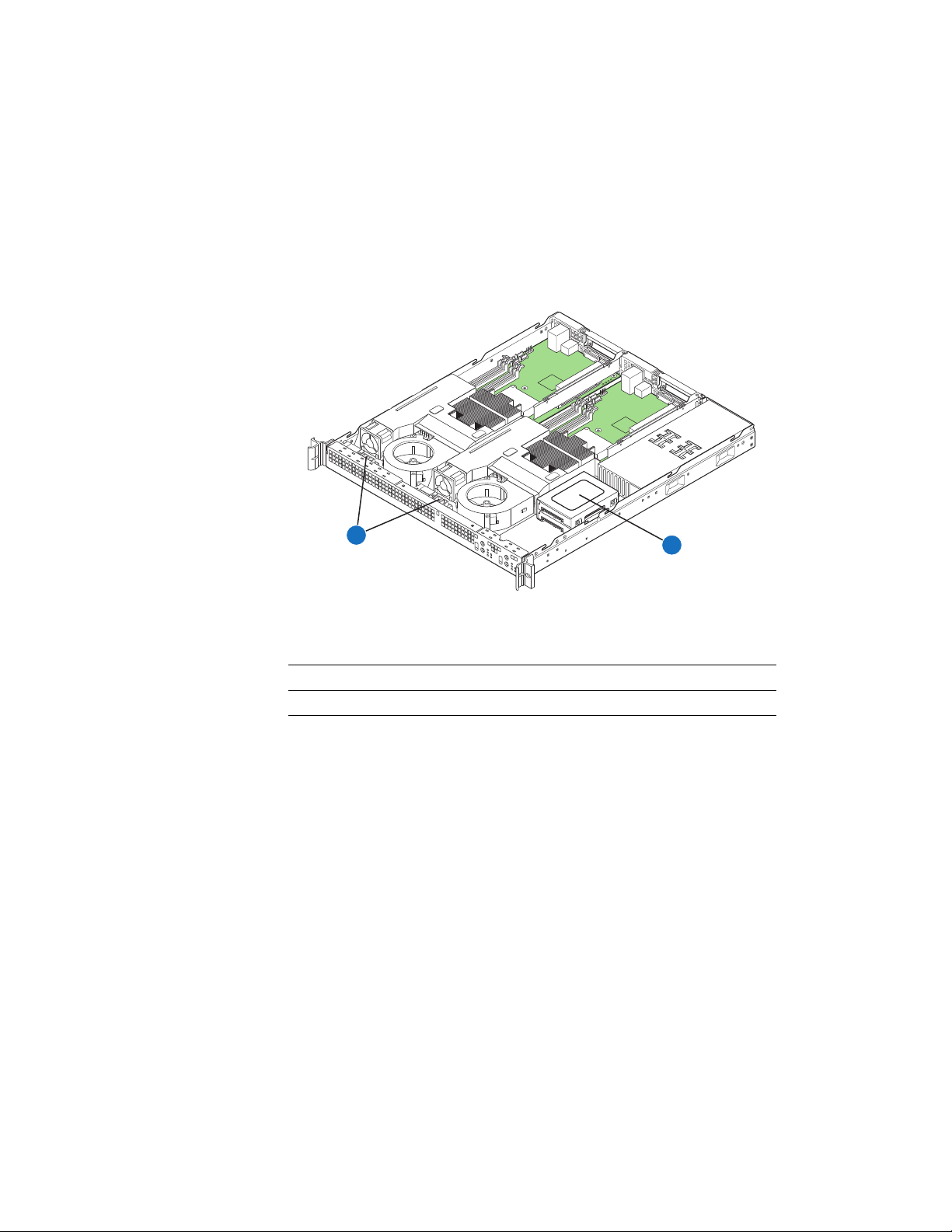
Internal Components
C
B
D
A
E
H
F
G
AF002493
A. Memory cooling fans (two) E. Power supply
B. Processor and memory air duct (two) F. Hard drive bracket (one bracket for two
2.5-inch drives)
C. Processor and heat sink (two) G. Front control panel (two)
D. PCI add-in card bracket (two) H. System blower fans (two)
Server Board Connectors
The two Intel® Server Boards X38ML have the same connectors / components.
Figure 5. System Components
8 Intel® Server System SR1520ML User’s Guide
Page 29
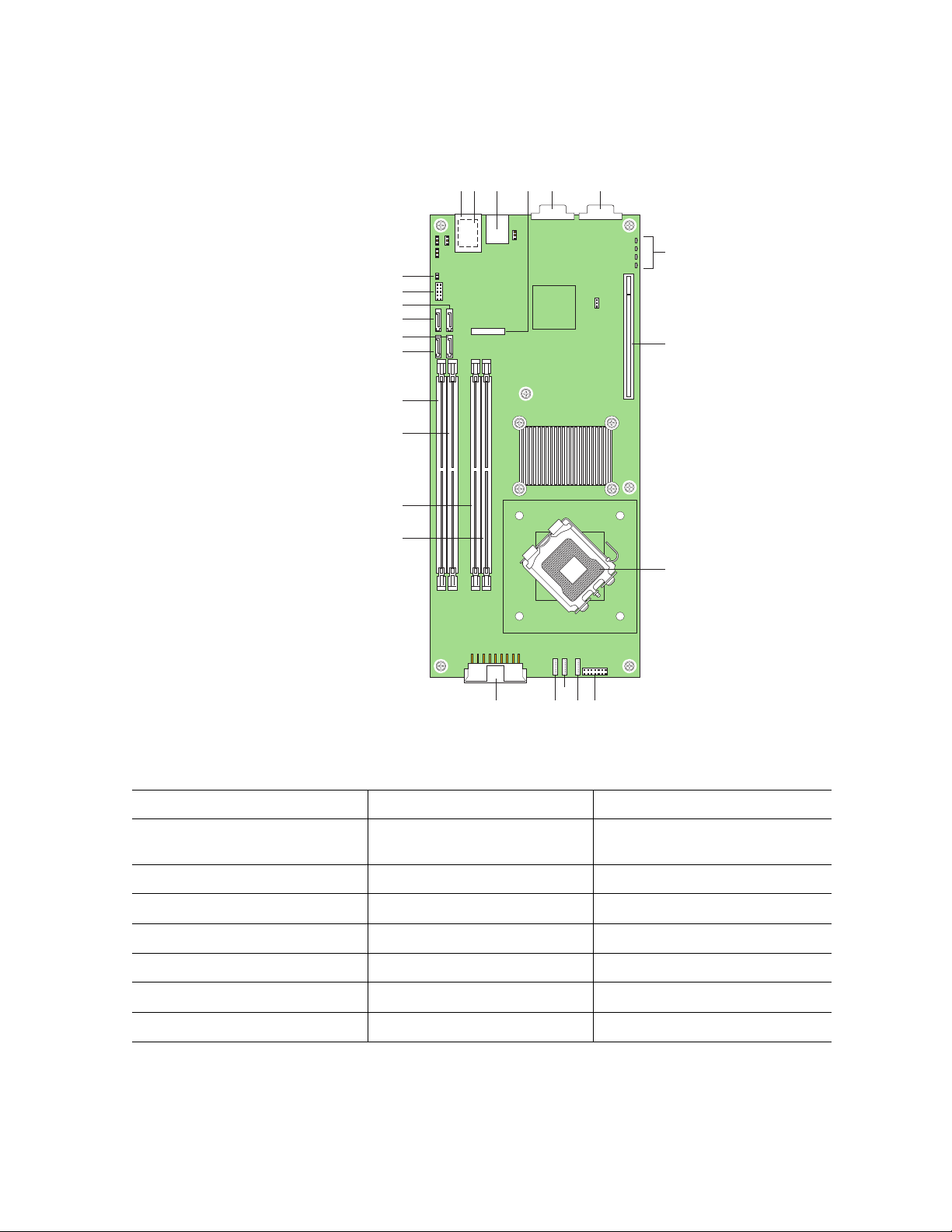
W
DCFEAB
G
X
V
U
T
S
H
R
Q
P
O
I
NMKJ
L
AF002498
A. NIC1 RJ45 connector (top) I. Processor socket Q. DIMM socket B1
B. USB port 0 (bottom)
USB port 1 (center)
C. NIC2 RJ45 connector K. System fan 3 S. SATA port 0
D. CMOS battery L. System fan 2 T. SATA port 1
E. Serial A DB9 connector M. System fan 1 U. SATA port 2
F. VGA connector N. Main power connector V. SATA port 3
G. POST LEDs O. DIMM socket A1 W. USB header for USB 2 and 3
H. PCI Express* x16 riser slot P. DIMM socket A2 X. Chassis intrusion header
J. Front panel connector R. DIMM socket B2
Figure 6. Server Board Connector Locations
Intel® Server System SR1520ML User’s Guide 9
Page 30
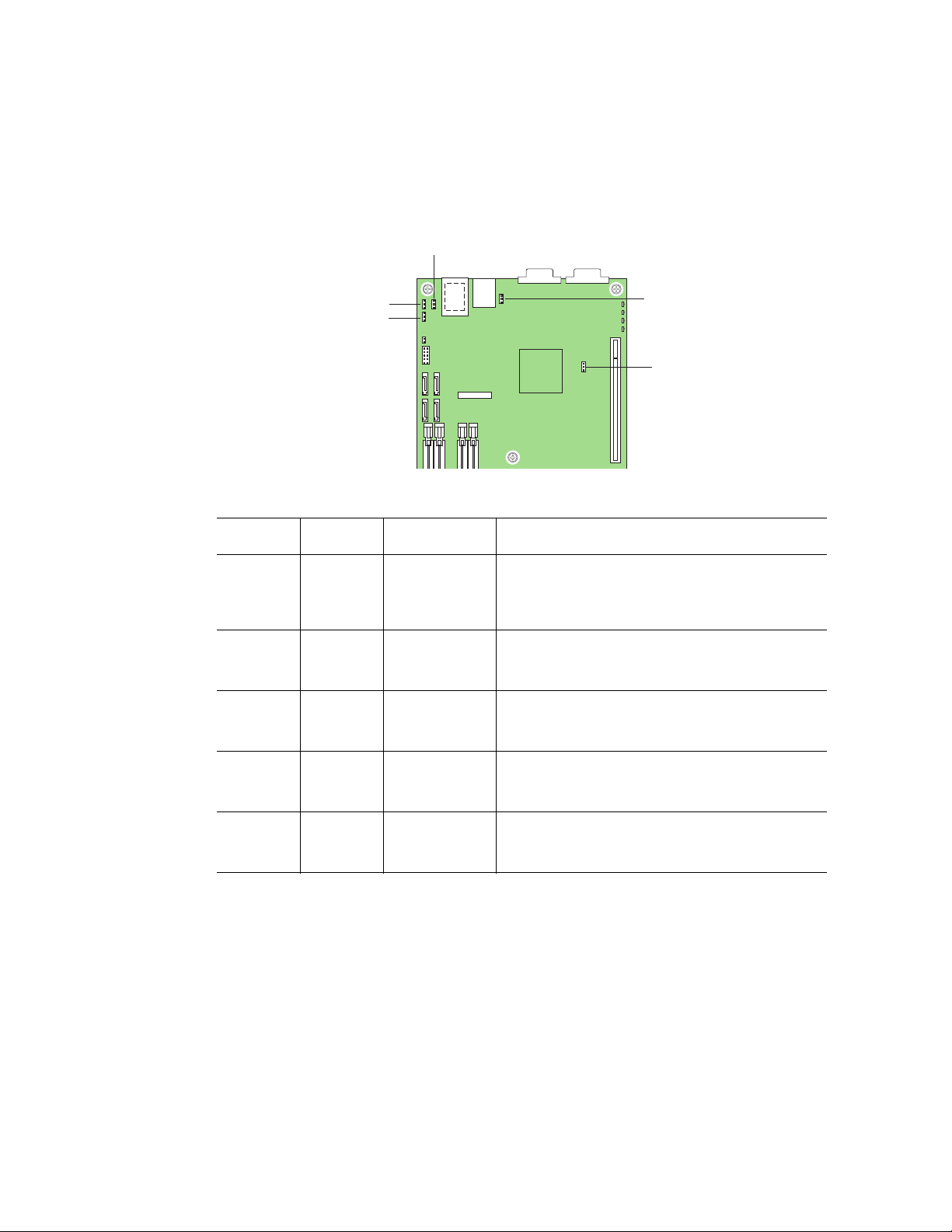
Configuration Jumpers
C
B
A
E
D
The two Intel® Server Boards X38ML have the same jumpers.
Callout Location Jumper Name Jumper Purpose
A J1A4 iBMC Boot
Block Write
Protect
B J1A2 BIOS
Recovery
Mode
C J1A3 CMOS Clear When pins 2-3 are jumpered, the CMOS settings
D J3A1 iBMC Force
Update Mode
E J6B1 Password
Clear
When pins 2-3 are jumpered, the iBMC boot block
is write enabled. When pins 1-2 are jumpered, the
iBMC boot block is write protected. Pins 1-2 should
be jumpered for normal operation.
When pins 2-3 are jumpered, the BIOS will be
recovered on the next boot. Pins 1-2 should be
jumpered for normal operation.
will be cleared on the next boot. Pins 1-2 should be
jumpered for normal operation.
When pins 2-3 are jumpered, the iBMC firmware
will be updated on the next boot. Pins 1-2 should
be jumpered for normal operation.
When pins 2-3 are jumpered, the administrator
and user passwords will be reset on the next boot.
Pins 1-2 should be jumpered for normal operation.
Figure 7. Configuration Jumpers
10 Intel® Server System SR1520ML User’s Guide
Page 31

SATA RAID Support
The Intel® Server System SR1520ML provides SATA (3.0 Gb/s) support.The embedded
SATA controller embedded supports both 1.5 and 3.0 Gbps data transfer rates. The Intel
RAID Technology solution, available with the ICH9R, offers data striping for higher
performance (RAID Level 0) and mirroring for higher reliability (RAID Level 1).
The BIOS Setup utility provides multiple drive configuration options on the Advanced |
ATA Controller setup page, some of which affect the ability to configure RAID. The
“Onboard SATA Controller” option is enabled by default. When this option is enabled, the
“Configure SATA as” option can be set to either IDE, AHCI, or RAID.
For assistance in navigating through the F2 BIOS Setup utility, see the Intel
Board X38ML Technical Product Specification.
For information about setting up RAID, see the RAID Software Guide that is included on
the Intel
®
Server Deployment Toolkit 2.0 CD.
Rack and Cabinet Mounting
The server system can be mounted into a 19-inch wide by up to a 30-inch deep server
cabinet. The system ships with a basic slide rail kit and supports optionsl fixed-mount and
tool-less slide rail kits:
• The basic slide rail kit mounts the system into a standard 19-inch wide by up to 30-
inch deep EIA-310D-compatible server cabinet. The product order code is
AXXBASICRAIL. This kit is included with your server system.
®
Server
®
• A fixed mount relay rack / cabinet mount kit can be configured to mount the system
into either a 2-post or 4-post rack cabinet. The product order code is
AXXBRACKETS. This kit is included with your server system.
• A tool-less full-extracting slide rail kit supports an optional cable management arm.
The product order code is AXXRACKCARM. This is an optional accessory that
must be ordered separately.
Hardware Requirements
To avoid integration difficulties and possible board damage, your system must meet the
requirements outlined below. For a list of qualified components, see the links under
"Server System References."
Intel® Server System SR1520ML User’s Guide 11
Page 32

Processor
Memory
Each server board must have one processor installed. Each board can use a different
processor. For a list of supported processors, see http://support.intel/com/support/
motherboards/server/X38ML.
Each server supports four DDR2 667 / 800 MHz unbuffered ECC DIMMs. The maximum
memory capacity is 2 GB unbuffered, 1 Gbit DDR2 memory. The minimum is one 256MB DIMM. The four slots are partitioned into Channel A and Channel B. Channel A
consists of DIMM A1 and DIMM A2. Channel Bconsists of DIMM B1 and DIMM B2.
DIMM A1 is the closest to the MCH.
DIMMs must meet the following requirements:
• If dual-channel operation is desired, Channel A and Channel B must be populated
identically (i.e., same capacity)
• Use DDR2 667 / 800 only.
• The speed used on all the channels is the slowest DIMM in the system
• Use ECC or non-ECC DIMMs
• You can mix different memory technologies (size and density)
• For single-channel mode, either channel may be used and DIMM sockets within the
same channel can be populated in any order
• For dual-channel interleaved mode, DIMM sockets may be populated in any order
as long as the total memory in each channel is the same.
• For dual-channel asymmetric mode, DIMM sockets may be populated in any order.
For a complete list of supported memory DIMMs, see http://support.intel/com/support/
motherboards/server/X38ML.
12 Intel® Server System SR1520ML User’s Guide
Page 33

2 Hardware Installations and
Upgrades
Caution: No components in the Intel® Server System SR1520ML are hot swappable. Before
removing or installing any component in this server system, you must first take the server
out of service, turn off all peripheral devices connected to the system, turn off the system
by pressing the power button(s), and unplug the AC power cord from the system or wall
outlet.
Before You Begin
Before working with your server product, pay close attention to the “Safety Information”
on page iii.
Tools and Supplies Needed
• Phillips* (cross head) screwdriver, #1 bit and #2 bit
• Antistatic wrist strap and conductive foam pad (recommended)
System References
All references to left, right, front, top, and bottom assume the reader is facing the front of
the server system as it would be positioned for normal operation.
Intel® Server System SR1520ML User’s Guide 13
Page 34

Removing and Installing the Server Cover
AF002500
B
C
A
Removing the Server System Cover
The server system must be operated with the cover in place to ensure proper cooling. You
will need to remove the cover to add or replace components inside of the server.
None of the internal components are hot-swappable. Before removing the server system
cover, power down the server and unplug all peripheral devices and the AC power cable.
Note: A nonskid surface or a stop behind the server system may be needed to prevent the server
system from sliding on your work surface.
1. Observe the safety and ESD precautions at the beginning of this book. See “Safety
Information” on page iii.
2. Turn off all peripheral devices connected to the server. Turn off the server.
3. Disconnect the AC power cord.
4. Remove the screw from the rear of the system. See letter “A” in the figure below.
5. Remove the two screws from the top of the system, at the front edge. See letter “B”
in the figure.
6. Push rearward on the top cover to slide the cover about 3/4 inch, until it stops, then
lift up on the cover to remove it. See letter “C”.
14 Intel® Server System SR1520ML User’s Guide
Figure 8. Removing the Server System Cover
Page 35

Installing the Server System Cover
1. Observe the safety and ESD precautions at the beginning of this book. See “Safety
Information” on page iii.
2. Place the cover over the server system so that the side edges of the cover sit just
outside of the server system sidewalls. Slide the cover forward. See letter “A” in the
figure below.
3. Insert the larger screw at the rear of the system. See letter “B” in the figure.
4. Insert the two small screws on the top surface of the cover, near the front edge. See
letter “C”.
B
A
C
AF002501
Figure 9. Installing the Server System Cover
5. Reconnect all peripheral devices and the AC power cord.
Installing and Removing a Hard Drive
Caution: The hard drives are NOT hot swappable. Before removing or replacing a hard drive, you
must first take the server out of service, turn off all peripheral devices connected to the
system, turn off the system by pressing the power button, and unplug the AC power cord
from the system or wall outlet.
One SATA drive can be installed for each server board (two drives total). Both drive bays
are at the right side of the chassis.
Intel® Server System SR1520ML User’s Guide 15
Page 36

Note: The server system does not support all hard drives. See “Server System References” on
page xix for an Internet link to a list of supported hardware.
Installing a Hard Drive
Note: If you are replacing a hard drive, see “Removing a Hard Drive” on page 18 for
instructions first. Return to these steps when directed.
1. Observe the safety and ESD precautions at the beginning of this book. See “Safety
Information” on page iii.
2. Power down the server. Unplug all peripheral devices and the AC power cable.
3. Remove the server system cover. For instructions, see “Removing the Server
System Cover” on page 14.
4. Remove the three screws that hold the hard drive bracket to the system. See letter
“A” in the figure below. For easiest access to the screws on the right side of the
hard drive bracket, lift the power supply from the system.
5. Lift the drive carrier from the system. See letter “B” in the figure.
A
B
AF002600
Figure 10. Removing Drive Carrier from the Server System
16 Intel® Server System SR1520ML User’s Guide
Page 37

6. Slide the drive into the carrier, connector side last. See letter “A” in the following
figure. If you are installing a drive for each server board, note which drive is on
bottom and which is on top to ensure you connect the cables correctly later.
7. Use the four screws provided to attach the drive to the carrier, two screws on each
side of the carrier. See letter “B” in the figure
B
A
AF002601
Note: For ease of assembly, connect the power and data cables before installing the drive
assembly into the server.
8. Connect one blue SATA cable between each drive and the SATA_0 port on each
server board if you installed two drives. Be sure to note which drive is connected to
which server board.
9. Connect the power cables to the drive(s):
— Connect the power cable labeled “P4” to the bottom drive.
— Connect the power cable labeled “P3” to the top drive.
10. Set the drive assembly into place in the chassis. See letter “A” in the figure below.
11. Attach the drive assembly to the chassis with the three screws that you removed
earlier. See letter “B” in the figure below.
Intel® Server System SR1520ML User’s Guide 17
Page 38

B
A
AF002509
Figure 11. Installing Drive Assembly
12. If you lifted out the power supply to access the drive bracket screws, set the power
supply back into place.
13. Install the server system cover. For instructions, see “Installing the Server System
Cover”.
Removing a Hard Drive
1. Observe the safety and ESD precautions at the beginning of this book. See “Safety
Information” on page iii.
2. Power down the server and unplug all peripheral devices and the AC power cable.
3. Remove the server system cover. For instructions, see “Removing the Server
System Cover” on page 14.
4. Remove the three screws that hold the hard drive bracket to the chassis. For easiest
access to the two screws on the right side, lift the power supply from the system.
See letter “A” in the figure below.
5. Lift the drive carrier from the chassis. See letter “B” in the figure.
18 Intel® Server System SR1520ML User’s Guide
Page 39

A
B
AF002603
Figure 12. Removing Drive Carrier
6. Disconnect the power and data cables from the drive.
7. Remove the four screws that attach the hard drive to the drive carrier. Lift the drive
from the carrier. Store the drive in an anti-static bag.
8. If you are installing a new drive, skip the rest of these steps and instead see
“Installing a Hard Drive” on page 16. Begin with step 6.
9. Insert the screws that held the drive in the carrier into the screw locations on the
carrier to store them for future use.
10. Set the drive assembly into place in the chassis. See letter “A” in the figure below.
11. Attach the drive assembly to the chassis with the three screws that you removed
earlier. See letter “B” in the figure below.
Intel® Server System SR1520ML User’s Guide 19
Page 40

B
A
AF002509
Figure 13. Installing the Drive Carrier
12. If you lifted out the power supply to access the drive bracket screws, set the power
supply back into place.
13. Install the server system cover. For instructions, see “Installing the Server System
Cover”.
Installing an Intel® Z-U130 Value Solid State Drive
Caution: The Intel® VSSD is NOT hot swappable. Before removing or replacing the Intel® VSSD,
you must first take the server out of service, turn off all peripheral devices connected to
the system, turn off the system by pressing the power button, and unplug the AC power
cord from the system or wall outlet.
1. Observe the safety and ESD precautions at the beginning of this book. See “Safety
Information” on page iii.
2. Power down the server and unplug all peripheral devices and the AC power cable.
3. Remove the server system cover. For instructions, see “Removing the Server
System Cover” on page 14.
4. Follow the instructions in the document titled Intel
Drive Mounting Kit Installation Guide for Intel
®
Z-U130 Value Solid State
®
Server Systems.
20 Intel® Server System SR1520ML User’s Guide
Page 41

Note: Your server system includes a USB Y-cable attached to the server board. One part of this
cable is attached to the front panel board. The other cable is loose. This loose cable is for
the Intel
®
VSSD.
5. Install the server system cover. For instructions, see “Installing the Server System
Cover”.
6. Plug all peripheral devices and the AC power cable into the server.
Installing and Removing the PCI Riser Assembly
Caution: The PCI riser assembly is NOT hot swappable. Before removing or replacing the PCI
riser assembly, you must first take the server out of service, turn off all peripheral devices
connected to the system, turn off the system by pressing the power button, and unplug the
AC power cord from the system or wall outlet.
Removing the PCI Riser Assembly
To remove the PCI riser assembly, use the following instructions.
1. Observe the safety and ESD precautions at the beginning of this book. See “Safety
Information” on page iii.
2. Power down the server and unplug all peripheral devices and the AC power cable.
3. Remove the server system cover. For instructions, see “Removing the Server
System Cover” on page 14.
4. Disconnect any cables attached to any add-in cards.
5. Remove the screw from the riser asssembly bracket. See letter “A” in the following
figure.
6. Lift up on the riser assembly to remove it. Use caution to gently ease the riser card
from the add-in card slot so you do not damage the slot or the riser card. See letter
“B” in the figure.
Intel® Server System SR1520ML User’s Guide 21
Page 42

A
B
AF002512
Figure 14. Removing PCI Riser Assembly
7. If you need to replace the PCI riser card, see “Removing and Installing the PCI
Riser Card” on page 24.
8. If you need to install or remove a PCI add-in card, see “Installing and Removing a
PCI Add-in Card” on page 26.
9. If you removed the PCI riser assembly as instructed in another procedure, continue
with that procedure.
Installing the PCI Riser Assembly
Note: For clarity, the figure in this series of instructions does not show an attached add-in card.
If you are installing an add-in card, do so before installing the PCI riser assembly into
your server system.
1. Lower the riser assembly into place over the add-in card slot. See letter “A” in the
following figure, aligning the tabs on the riser assembly with the matching slot at
the back of the server system, and aligning the riser card with the slot in the server
board.
2. Press down uniformly until the riser card is seated on the server board.
3. Insert the screw into the riser asssembly bracket. See letter “B” in the figure.
22 Intel® Server System SR1520ML User’s Guide
Page 43

B
A
AF002513
Figure 15. Installing PCI Riser Assembly into the Server System
4. Install the server system cover. For instructions, see “Installing the Server System
Cover”.
Intel® Server System SR1520ML User’s Guide 23
Page 44

Removing and Installing the PCI Riser Card
Caution: The PCI riser card is NOT hot swappable. Before removing or replacing the PCI riser
card, you must first take the server out of service, turn off all peripheral devices connected
to the system, turn off the system by pressing the power button, and unplug the AC power
cord from the system or wall outlet.
Removing the PCI Riser Card
1. Observe the safety and ESD precautions at the beginning of this book. See “Safety
Information” on page iii.
2. Power down the server and unplug all peripheral devices and the AC power cable.
3. Remove the server system cover. For instructions, see “Removing the Server
System Cover” on page 14.
4. Disconnect any cables attached to any add-in cards.
5. Remove the PCI riser assembly. For instructions, see “Removing the PCI Riser
Assembly” on page 21.
6. Remove the add-in card from the PCI riser connector if an add-in card is installed.
For instructions, see “Removing a PCI Add-in Card” on page 27.
7. Remove the two screws that attach the riser card to the riser assembly. See the
following figure. Save these screws for later.
B
A
AF002533
Figure 16. Removing Riser Card from Riser Assembly
8. Install the replacement riser card. For instructions, see “Installing a PCI Riser
Card” on page 25.
9. Choose the appropriate action:
— Install an add-in card. For instructions, see “Installing a PCI Add-in Card” on
page 26.
24 Intel® Server System SR1520ML User’s Guide
Page 45

— Install the PCI riser assembly into the server system. For instructions, see
“Installing the PCI Riser Assembly” on page 22.
Installing a PCI Riser Card
1. Observe the safety and ESD precautions at the beginning of this book. See “Safety
Information” on page iii.
2. Power down the server and unplug all peripheral devices and the AC power cable.
3. Remove the server system cover. For instructions, see “Removing the Server
System Cover”.
4. Disconnect any cables attached to any add-in cards.
5. Remove the PCI riser assembly. For instructions, see “Removing the PCI Riser
Assembly” on page 21.
6. Remove any add-in cards from the PCI riser connector. For instructions, see
“Removing a PCI Add-in Card” on page 27.
7. Use two screws to attach the riser card to the riser assembly. See the figure below.
A
B
AF002650
Figure 17. Installing Riser Card onto Riser Assembly
8. Choose the appropriate action:
— Install a PCI add-in card if desired. For instructions, see “Installing a PCI Add-
in Card” on page 26.
— Install the PCI riser assembly into the server system. For instructions, see
“Installing the PCI Riser Assembly” on page 22.
Intel® Server System SR1520ML User’s Guide 25
Page 46

Installing and Removing a PCI Add-in Card
Caution: The add-in cards are NOT hot swappable. Before removing or replacing an add-in card,
you must first take the server out of service, turn off all peripheral devices connected to
the system, turn off the system by pressing the power button, and unplug the AC power
cord from the system or wall outlet.
Installing a PCI Add-in Card
1. Observe the safety and ESD precautions at the beginning of this book. See “Safety
Information” on page iii.
2. Power down the server and unplug all peripheral devices and the AC power cable.
3. Remove the server system cover. For instructions, see “Removing the Server
System Cover” on page 14.
4. Remove the PCI riser assembly. For instructions, see “Removing the PCI Riser
Assembly” on page 21.
5. Remove the screw from the add-in card slot opening.
6. If a filler panel is installed over the opening at the rear of the riser assembly,
remove it. Save the filler panel in case you later need to remove the add-in card.
7. Insert the add-in card into the socket in the riser assembly. Push the add-in card into
place firmly until it seats in the riser card connector, but use caution so you do not
twist or bend the card. See letter “A” in the figure.
8. Re-install the screw you removed in step 5. See letter “B” in the figure.
B
A
AF002515
Figure 18. Installing an Add-In Card
26 Intel® Server System SR1520ML User’s Guide
Page 47

9. Connect any necessary cables to the add-in card. See your add-in card
documentation for information.
10. Install the PCI riser assembly into the server system. For instructions, see
“Installing the PCI Riser Assembly” on page 22.
Removing a PCI Add-in Card
1. Observe the safety and ESD precautions at the beginning of this book. See “Safety
Information” on page iii.
2. Power down the server and unplug all peripheral devices and the AC power cable.
3. Remove the server system cover. For instructions, see “Removing the Server
System Cover” on page 14.
4. Remove the PCI riser assembly. For instructions, see “Removing the PCI Riser
Assembly” on page 21.
5. Remove the screw at the rear of the riser assembly. See letter “A” in Figure 19.
Save this screw. You will use it later.
6. Pull the add-in card from the roser assembly socket. Use caution so you do not twist
or bend the card. See letter “A” in the figure.
7. If you are not installing a replacement add-in card, install a filler panel over the
opening at the rear of the riser assembly.
8. Re-install the screw you removed in step 5. See letter “B” in the figure.
B
A
AF002514
Figure 19. Removing an Add-In Card
Intel® Server System SR1520ML User’s Guide 27
Page 48

Note: Make sure that all empty add-in card slots have filler panels installed.
9. Install the PCI riser assembly into the server system. For instructions, see
“Installing the PCI Riser Assembly” on page 22.
Removing and Installing the Processor Air Duct
Always operate your server system with the processor air duct in place. The air duct is
required for proper airflow within the server system.
Removing the Processor Air Duct
1. Observe the safety and ESD precautions at the beginning of this book. See “Safety
Information” on page iii.
2. Power down the server and unplug all peripheral devices and the AC power cable.
3. Remove the server system cover. For instructions, see “Removing the Server
System Cover”.
4. Lift the processor air duct from its location behind the two fans.
AF002502
Figure 20. Removing the Processor Air Duct
28 Intel® Server System SR1520ML User’s Guide
Page 49

Installing the Processor Air Duct
1. Observe the safety and ESD precautions at the beginning of this book. See “Safety
Information” on page iii.
2. Power down the server and unplug all peripheral devices and the AC power cable.
3. Remove the server system cover. For instructions, see “Removing the Server
System Cover” on page 14.
4. Lower the air duct into place. Use caution so you do not pinch or disengage cables
that may be near or under the air duct.
AF002503
Figure 21. Installing the Processor Air Duct
5. Install the server system cover. For instructions, see “Installing the Server System
Cover”.
Installing and Removing Memory
Caution: The memory is NOT hot swappable. Before removing or replacing any memory DIMM,
you must first take the server out of service, turn off all peripheral devices connected to
the system, turn off the system by pressing the power button, and unplug the AC power
cord from the system or wall outlet.
Intel® Server System SR1520ML User’s Guide 29
Page 50

The silkscreen on the board for the DIMMs displays DIMMB2, DIMMB1, DIMMA2,
DIMMA1 starting from the edge of the board. DIMMA1 is the socket closest to the
processor socket. See “Memory” on page 12 for a discussion of the memory requirements
and options. See “Server System References” on page xix for a link to the list of tested
DIMMs.
Memory Population Rules
Each server board in the Intel® Server System SR1520ML provides four DIMM sockets
across two banks. For each server board, Bank 1 consists of DIMM sockets A1 and B1.
Bank 2 consists of DIMM sockets A2 and B2. For single-channel operation, either
channel may be used and DIMM sockets within the same channel can be populated in any
order. For dual-channel asymetric mode, DIMM sockets may be populated in any order.
DIMMs must meet the following requirements:
• The minimum memory is one 256 MB DIMM in socket A1 on each server board.
Socket A1 is the blue socket that is the closest to the senter of the server board. This
provides single-channel mode for each server board,
• Use only DIMMs with DDR2 DRAM technology.
• Use only DDR2-667 and DDR2-800 stacked DIMM modules. The speed used on all
channels is that of the slowest DIMM on the server board.
For dual-channel operation, the following conditions must be met:
• Populate two identical DIMMs in sockets DIMMA1 and DIMM B1. These are the
two blue sockets
• Populate four identical DIMMs in each socket location.
For a complete list of supported memory DIMMs, see http://support.intel/com/support/
motherboards/server/X38ML.
Installing DIMMs
To install DIMMs, follow these steps:
1. Observe the safety and ESD precautions at the beginning of this book. See “Safety
Information” on page iii.
2. Power down the server and unplug all peripheral devices and the AC power cable.
3. Remove the server system cover. For instructions, see “Removing the Server
System Cover” on page 14.
4. Remove the processor air duct. For instructions, see “Removing the Processor Air
Duct” on page 28.
5. Locate the DIMM sockets. See Figure 22.
30 Intel® Server System SR1520ML User’s Guide
Page 51

C
D
B
A
DIMM Socket B2
DIMM Socket B1
DIMM Socket A2
DIMM Socket A1
AF002519
Figure 22. Installing Memory DIMMs
6. Make sure the clips at both ends of the DIMM socket(s) are pushed outward to the
open position. See letter “A” in Figure 22.
7. Holding the DIMM by the edges, remove it from its anti-static package.
8. Position the DIMM above the socket. Align the notch on the bottom edge of the
DIMM with the key in the DIMM socket. See letter “B” in the figure.
9. Insert the bottom edge of the DIMM into the socket. See letter “C” in the figure.
10. When the DIMM correctly positioned, push down on the top edge of the DIMM
until the retaining clips snap into place.
11. Make sure the clips are firmly in place. See letter “D” in the figure.
12. Install the processor air duct. For instructions, see “Installing the Processor Air
Duct” on page 29.
13. Install the server system cover. For instructions, see “Installing the Server System
Cover”.
Intel® Server System SR1520ML User’s Guide 31
Page 52

Removing DIMMs
To remove a DIMM, follow these steps:
1. Observe the safety and ESD precautions at the beginning of this book. See “Safety
Information” on page iii.
2. Power down the server and unplug all peripheral devices and the AC power cable.
3. Remove the server system cover. For instructions, see “Removing the Server
System Cover” on page 14.
4. Remove the processor air duct. For instructions, see “Removing the Processor Air
Duct” on page 28.
5. Locate the DIMM sockets. See Figure 22.
6. Gently spread the retaining clips at each end of the socket. See letter “A” in the
following figure. The DIMM lifts from the socket. See letter “B” in the figure.
7. Holding the DIMM by the edges, lift it from the socket, and store it in an anti-static
package.
8. Close the DIMM socket clips. See letter “C”.
B
C
A
DIMM Socket B2
DIMM Socket B1
DIMM Socket A2
DIMM Socket A1
AF002518
Figure 23. Removing Memory DIMMs
32 Intel® Server System SR1520ML User’s Guide
Page 53

9. Install the processor air duct. For instructions, see “Installing the Processor Air
Duct” on page 29.
10. Install the server system cover. For instructions, see “Installing the Server System
Cover”.
Replacing the Processor
Note: This manual assumes a processor is already installed and you are referring to these steps
to replace your processor. If you are setting up this system for the first time, see the Quick
Start User’s Guide that was included in the product box.
Caution: Use only processors that have been validated to work with this server board. See “Server
System References” on page xix for a link to the list of compatible processor(s).
Caution: ESD and handling processors: Reduce the risk of electrostatic discharge (ESD) damage to
the processor by doing the following: (1) Touch the metal chassis before touching the
processor or server board. Keep part of your body in contact with the metal chassis to
dissipate the static charge while handling the processor. (2) Avoid moving around
unnecessarily.
Removing the Heat Sink and Processor
1. Observe the safety and ESD precautions at the beginning of this book. See “Safety
Information” on page iii.
2. Power down the server and unplug all peripheral devices and the AC power cable.
3. Remove the server system cover. For instructions, see “Removing the Server
System Cover” on page 14.
4. Remove the processor air duct. For instructions, see “Removing the Processor Air
Duct” on page 28.
5. Loosen the four captive screws on the corners of the heat sink.
6. Twist the heat sink slightly to break the seal between the heat sink and the
processor.
7. Lift the heat sink from the processor. If it does not pull up easily, twist the heat sink
again. Do not force the heat sink from the processor. Doing so could damage the
processor.
8. Raise the processor socket handle completely. See the following figure.
Intel® Server System SR1520ML User’s Guide 33
Page 54

AF000095
Figure 24. Opening the Processor Socket Handle
9. Push the rear tab with your finger to slightly lift the front of the load plate. Raise the
load plate completely. Raise the CPU load plate. See the following figure.
AF000415
Figure 25. Opening the Load Plate
Caution: Do not touch the socket pins; they are very sensitive and easily damaged.
10. Lift the processor from the socket. See the following figure.
34 Intel® Server System SR1520ML User’s Guide
Page 55

AF000416
Figure 26. Removing the Processor
11. Continue with the steps under “Installing the Processor”.
Installing the Processor
These steps assume you have just removed your heat sink and processor and your server
system is powered down and unplugged. If this is not true, see “Removing the Heat Sink
and Processor” on page 33 before following these steps.
Caution: Do not touch the socket pins; they are very sensitive and easily damaged.
1. Remove the processor from the packaging box and remove the protective shipping
cover.
2. Orient the processor with the socket so the processor cutouts match the socket
notches, then set the processor into place.
Intel® Server System SR1520ML User’s Guide 35
Page 56

AF000101
Figure 27. Installing the Processor
Note: Make sure the alignment triangle mark and the alignment triangle cutout align correctly.
3. Lower the CPU load plate.
4. Lower the socket lever.
5. Install the heat sink. For instructions, see the following steps.
Installing the Heat Sink
Install the processor before installing the heat sink. For instructions, see “Installing the
Processor” on page 35.
Caution: The heat sink has Thermal Interface Material (TIM) located on the bottom of it. Use
caution when you unpack the heat sink so you do not damage the TIM.
1. Remove the protective cover from the TIM on the underside of the heat sink. Do
not touch the TIM.
2. Orient the heat sink over the processor as shown by Figure 28. The fins must be
positioned as shown to provide correct airflow through the system.
3. Set the heat sink over the processor, lining up the four captive screws with the four
posts surrounding the processor.
4. Loosely screw in the captive screws on the heat sink corners in a diagonal manner
as shown by the four circled numbers in the figure below. Do no fully tighten one
screw before tightening another.
36 Intel® Server System SR1520ML User’s Guide
Page 57

5. Gradually and equally tighten each captive screw in the same order until each is
firmly tightened.
A
2
3
B
1
4
AF002517
Figure 28. Installing the Heat Sink
6. Install the processor air duct. For instructions, see “Installing the Processor Air
Duct” on page 29.
7. Install the server system cover. For instructions, see “Installing the Server System
Cover”.
Replacing the Power Supply
Caution: The power supply is NOT hot swappable. Before removing or replacing the power supply,
you must first take the server out of service, turn off all peripheral devices connected to
the system, turn off the system by pressing the power button, and unplug the AC power
cord from the system or wall outlet.
The power supply can be replaced if it fails or if one of the fans that is integrated into it
fails. To replace the power supply, use the following instructions.
1. Observe the safety and ESD precautions at the beginning of this book. See “Safety
Information” on page iii.
2. Power down the server and unplug all peripheral devices and the AC power cable.
Intel® Server System SR1520ML User’s Guide 37
Page 58

3. Remove the server system cover. For instructions, see “Removing the Server
System Cover”.
4. Disconnect all power cables connected to the server board and peripherals. See
Figure 29:
— From each server board, disconnect the main power cable. This connector is
labeled P1 for the board on the right, and P2 for the board on the left. See letters
“A” and “B” in the following figure
— From each hard drive, disconnect the power cable. The connector to the top
drive is labeled P3 and the connector to the bottom drive is labeled P4. See
letters “C” and “D” in the figure.
.
A
B
D
C
AF002580
Figure 29. Disconnecting Power Cables
38 Intel® Server System SR1520ML User’s Guide
Page 59

5. Push back on the tab for the cable harness to release the bundle of cables.
6. Lift the cable bundle from the harness.
7. Lift up on the power supply to remove it.
Note: While lifting the system to remove it, carefully untangle the power supply cables inside the
system if necessary.
A
B
AF002524
Figure 30. Removing Power Supply
8. Slide the rear edge of the replacement power supply into place, lining up with the
rear of the server system. See letter “A” in the following figure.
9. Set the front of the power supply down, ensuring it sits behind the metal tab in the
bottom of the system. See letter “B” in the figure.
10. Push the bundle of cables into place between the drive carriers and the wall of the
system.
11. Insert the cable bundle into the cable harness and then close the harness over the
cables.
Intel® Server System SR1520ML User’s Guide 39
Page 60

C
A
B
B
AF002525
Figure 31. Installing Power Supply Module
12. Route the cable with the connector labeled P2 in front of both front blower
assemblies.
13. Route the cable with the connector labeled P1 in front of the right front blower
assembly.
14. Connect the power cables to the server board and peripherals. See Figure 29:
— On each board, connect the main power cable. This connector is labeled P1 for
the board on the right, and P2 for the board on the left. See letters “A” and “B”
in Figure 29 on page 38.
— On each hard drive, connect the power cable. The connector to the top drive is
labeled P3 and the connector to the bottom drive is labeled P4. See letters “C”
and “D” in Figure 29 on page 38
15. Install the server system cover. For instructions, see “Installing the Server System
Cover”.
16. Plug all peripheral devices and the AC power cable into the server.
Replacing the Fans
The individual blower fans and memory cooling fans can be replaced if a fan fails. The
fans that are integrated into the power supply cannot be replaced. If one of the fans in the
power supply fails, the power supply must be replaced.
Caution: The fans are NOT hot swappable. Before removing or replacing the fan assembly, you
must first take the server out of service, turn off all peripheral devices connected to the
system, turn off the system by pressing the power button, and unplug the AC power cord
from the system or wall outlet.
40 Intel® Server System SR1520ML User’s Guide
Page 61

Replacing a Blower Fan
B
A
1. Observe the safety and ESD precautions at the beginning of this book. See “Safety
Information” on page iii.
2. Power down the server and unplug all peripheral devices and the AC power cable.
3. Remove the server system cover. For instructions, see “Removing the Server
System Cover”.
4. Remove the processor air duct. For instructions, see “Removing the Processor Air
Duct” on page 28.
5. The fan cables are tucked underneath the main power supply cable. For ease of
access, disconnect the main power supply cable on both server boards. See letter
“A” in the following figure.
6. Disconnect the fan cable from each server board. See letter “B” in the figure.
Figure 32. Disconnecting Cables
Intel® Server System SR1520ML User’s Guide 41
7. Remove the five screws that hold the fan bracket in place. Save these screws. You
will re-install them later. See letter “A” in the figure below.
8. Lift the fan bracket with the attached fans from the server, working it out from
underneath the front panel, USB, and SATA cables. See letter “B” in the figure.
Page 62

A
B
AF002507
Figure 33. Removing Bracket and Fans
42 Intel® Server System SR1520ML User’s Guide
Page 63

9. Turn the bracket over and remove the two screws that attach the failed fan to the
bracket. Save these screws. You will reinstall them later. See letter “A” in the figure
below.
10. Lift the fan from the bracket. See letter “B”.
B
A
AF002535
Figure 34. Removing Fan from Fan Bracket
11. Install the replacement fan onto the bracket, using the two screws you removed in
step 9.
12. Set the fan assembly into the system. Use caution to make sure you do not pinch
any cables.
13. Connect the fan cables to the Fan_3 connectors on each server board.
14. Route the front panel cables and the main power cables between the blower fan and
the memory cooling fans.
15. Route the left USB and SATA cables between the left blower fan and left memory
cooling fan.
16. Route the right USB and SATA cables between the left side of the right memory
cooling fan and the right side of the left blower fan.
17. Route the left main power cable between the the left blower fan and left memory
cooling fan.
18. Route the right main power cable between the right blower fan and the right
memory cooling fan.
19. Bundle the fan cables for each board together. Hold them in place under the cable
for the main power cable while you connect the main power cables. Use caution to
make sure you do not pinch any cables when you connect the main power supply
connectors. Make sure the fan cables will not block airflow from the memory
cooling fans.
Intel® Server System SR1520ML User’s Guide 43
Page 64

20. Install the processor air duct. For instructions. see “Installing the Processor Air
Duct” on page 29.
Replacing a Memory Cooling Fan
1. Observe the safety and ESD precautions at the beginning of this book. See “Safety
Information” on page iii.
2. Power down the server and unplug all peripheral devices and the AC power cable.
3. Remove the server system cover. For instructions, see “Removing the Server
System Cover”.
4. Remove the processor air duct. For instructions, see “Removing the Processor Air
Duct” on page 28.
5. (optional) The fan cables are tucked underneath the main power supply cable. For
ease of access, disconnect the main power supply. See letter “A” in the following
figure.
6. Follow the fan cable from the failed fan to the Y-connector. Detach the fan cable at
they Y-connector. See letter “B” in the figure.
7. Remove the two screws that attach the fan to the fan bracket. Save these screws.
You will re-install them later. See letter “C”.
8. Remove the fan. See letter “D”.
A
C
D
AF002504
Figure 35. Disconnecting Memory Cooling Fan Cable
B
44 Intel® Server System SR1520ML User’s Guide
Page 65

9. Set the replacement fan into place. See letter “A” in the following figure. When
AF002504
B
A
D
correctly positioned, the fan cable extends from the top right side of the fan, at the
rear.
10. Install the screws you removed in step 7 to secure the fan to the bracket. See letter
“B” in the figure.
11. Connect the fan cable at the Y-connector. See letter “C”
12. If you removed the main power cable, bundle the fan cables together and hold them
in place under the cable for the main power cable while you connect the main
power cables. Use caution to make sure you do not pinch any cables when you
connect the main power supply connectors. Make sure the fan cables will not block
airflow from the memory cooling fans. See letter “D”
Figure 36. Connecting Memory Cooling Fan Cable
13. Install the processor air duct. For instructions. see “Installing the Processor Air
Duct” on page 29.
Intel® Server System SR1520ML User’s Guide 45
Page 66

Replacing a Server Board
Removing the Server Board
1. Observe the safety and ESD precautions at the beginning of this book. See “Safety
Information” on page iii.
2. Power down the server and unplug all peripheral devices and the AC power cable.
3. Remove the server system cover. For instructions, see “Removing the Server
System Cover” on page 14.
4. Remove the processor air duct. For instructions, see “Removing the Processor Air
Duct” on page 28.
5. Remove the PCI riser assembly. For instructions, see “Removing the PCI Riser
Assembly” on page 21.
6. Detach all cables connected at the front of the server board:
Note: Use caution when disconnecting cables. Pull only on the cable connector, not on the
cable.
— Main power. The cable end is labeled P1 for the server board at the right and P2
for the server board at the left. Press and hold down on the tab at the center of
the connector while you pull on the connector.
— Front panel
— Sys_fan_3
7. Detach the cables connected at the rear of the server board:
— USB_2_3
—SATA_0
8. Remove the heat sink and the processor. For instructions, see “Removing the Heat
Sink and Processor” on page 33.
9. Remove the DIMMs. For instructions, see “Removing DIMMs” on page 32.
10. Remove the six screws from the server board (see letter “A”) and lift the server
board from the server system (see letter “B”).
46 Intel® Server System SR1520ML User’s Guide
Page 67

A
Figure 37. Removing the Server Board
11. Choose the appropriate action:
B
AF002520
— Install a replacement the server board. For instructions, see “Installing the
Server Board” on page 48.
— Continue with the following steps to reassemble and close the server system
without replacing the server board.
12. Install the processor air duct. For instructions, see “Installing the Processor Air
Duct” on page 29.
13. Install the server system cover. For instructions, see “Installing the Server System
Cover”.
14. Plug all peripheral devices and the AC power cable into the server.
15. Store the components you removed (processor, DIMMs, PCI riser assembly, server
board) in anti-static bags for future use.
Intel® Server System SR1520ML User’s Guide 47
Page 68

Installing the Server Board
1. Observe the safety and ESD precautions at the beginning of this book. See “Safety
Information” on page iii.
2. Power down the server and unplug all peripheral devices and the AC power cable.
3. Remove the server system cover. For instructions, see “Removing the Server
System Cover” on page 14.
4. Remove the processor air duct. For instructions, see “Removing the Processor Air
Duct” on page 28.
5. Remove the PCI riser assembly. For instructions, see “Removing the PCI Riser
Assembly” on page 21.
6. Place the server board into the server system as shown by letter “A” in the figure
below.
7. Attach the server board with six screws. See letter “B” in the figure.
B
A
AF002521
Figure 38. Installing the Server Board
8. Install the processor and the heat sink. For instructions, see “Installing the
Processor” on page 35.
9. Install the system memory. For instructions, see “Installing DIMMs” on page 30.
48 Intel® Server System SR1520ML User’s Guide
Page 69

Notes:
• Use caution when connecting cables to make sure you do not pinch any cables.
• For data cable routing information, see “Cable Routing” on page 67.
• For power cable routing information, see “Cable Routing” on page 67.
10. Connect the cables at the front of the server board.
— Main power. The cable end is labeled P1 for the server board at the right and P2
for the server board at the left. Several cables lay underneath this connector. Be
sure the cables do not get pinched in the connector. See letter “A” in the
following figure.
— Front panel (letter “E”)
— Sys_fan_3 (letter “D”)
11. Connect the cables at the rear of the server board.
— USB_2_3 (letter “C”)
— SATA_0 (letter “B”)
C
B
A
D
E
AF002531
Figure 39. Connecting Cables to Server Board
Intel® Server System SR1520ML User’s Guide 49
Page 70

12. Install the PCI riser assembly. For instructions, see “Installing the PCI Riser
Assembly” on page 22.
13. Install the processor air duct. For instructions, see “Installing the Processor Air
Duct” on page 29.
14. Install the server system cover. For instructions, see “Installing the Server System
Cover”.
15. Plug all peripheral devices and the AC power cable into the server.
Replacing the Front Panel Board
Caution: The control panel is NOT hot swappable. Before removing or replacing the control panel,
you must first take the server out of service, turn off all peripheral devices connected to
the system, turn off the system by pressing the power button, and unplug the AC power
cord from the system or wall outlet.
Your server must be operated with a control panel installed.
1. Observe the safety and ESD precautions at the beginning of this book. See “Safety
Information” on page iii.
2. Power down the server and unplug all peripheral devices and the AC power cable.
3. Remove the server system cover. For instructions, see “Removing the Server
System Cover” on page 14.
4. Remove the power supply cables from the cable harness.
5. (optional) For easier access, lift the power supply from place.
Note: For ease of access, lift the front panel board from the server before disconnecting the
cables.
6. Remove the screw that attaches the front panel board to the server system. See
letter “A” in the figure below. Save these screws. You will re-install them later.
7. Slide the front panel board rearward and then lift it from the server. See letter “B”
in the figure.
Caution: When disconnecting the cables to the front panel board, be careful not to bend or twist the
board.
8. Disconnect the front panel cable and the USB cables from the front panel board.
For ease of identification, the USB cables are two different colors. Note which
color is attached to which server board.
50 Intel® Server System SR1520ML User’s Guide
Page 71

A
B
C
C
AF002510
Figure 40. Removing Front Panel Board
Note: For ease of access, connect the cables before installing the front panel board.
9. Connect the USB and front panel cables to the replacement front panel board. See
letter “A” in the following figure.
10. Set the front panel board into place, inserting the two knobs on the floor of the
system through the two holes in the front panel board. See letter “B” in the figure.
11. Slide the front panel board foward to match the screw holes in the board and
system. Screw the front panel board into place. See letter s “C” and “D” in the
figure.
Intel® Server System SR1520ML User’s Guide 51
Page 72

D
C
A
B
AF002511
Figure 41. Installing Front Panel Board
12. Tuck the USB and SATA cables into place under the lip at the front of the system.
13. If you removed the power supply, set it back into place.
14. Route the power cables into the cable harness.
15. Install the server system cover. For instructions, see “Installing the Server System
Cover”.
16. Plug all peripheral devices and the AC power cable into the server.
Replacing the CMOS Battery
Caution: The CMOS battery is NOT hot swappable. Before removing or replacing the CMOS
battery, you must first take the server out of service, turn off all peripheral devices
connected to the system, turn off the system by pressing the power button, and unplug the
AC power cord from the system or wall outlet.
52 Intel® Server System SR1520ML User’s Guide
Page 73

The lithium battery on the server board powers the RTC in the absence of power. When
the battery starts to weaken, it loses voltage, and the server settings stored in CMOS RAM
in the RTC (for example, the date and time) may be wrong. Contact your customer service
representative or dealer for a list of approved devices.
Warni n g: Danger of explosion if battery is incorrectly replaced. Replace only with the same or
equivalent type recommended by the equipment manufacturer. Discard used batteries
according to manufacturer's instructions.
Advarsel: Lithiumbatteri - Eksplosionsfare ved fejlagtig håndtering. Udskiftning må kun ske med
batteri af samme fabrikat og type. Levér det brugte batteri tilbage til leverandøren.
Advarsel: Lithiumbatteri - Eksplosjonsfare. Ved utskifting benyttes kun batteri som anbefalt av
apparatfabrikanten. Brukt batteri returneres apparatleverandøren.
Va r n i n g : Explosionsfara vid felaktigt batteribyte. Använd samma batterityp eller en ekvivalent typ
som rekommenderas av apparattillverkaren. Kassera använt batteri enligt fabrikantens
instruktion.
Varoitus: Paristo voi räjähtää, jos se on virheellisesti asennettu. Vaihda paristo ainoastaan
laitevalmistajan suosittelemaan tyyppiin. Hävitä käytetty paristo valmistajan ohjeiden
mukaisesti.
1. Observe the safety and ESD precautions at the beginning of this book. See “Safety
Information” on page iii.
2. Power down the server and unplug all peripheral devices and the AC power cable.
3. Remove the server system cover. For instructions, see “Removing the Server
System Cover” on page 14.
4. Remove the server's cover and locate the battery. See Figure 42.
5. Pull back gently on the metal tab at the top of the battery.
6. Remove the battery from its socket.
Intel® Server System SR1520ML User’s Guide 53
Page 74

AF002522
Figure 42. Removing the CMOS Battery
7. Dispose of the battery according to local ordinance.
8. Remove the new lithium battery from its package, and, being careful to observe the
correct polarity, insert it in the battery socket. The “+” sign needs to face the rear of
the system.
9. Install the system cover. For instructions, see “Installing the Server System Cover”
on page 15.
10. Run the BIOS Setup utility to restore the configuration settings.
54 Intel® Server System SR1520ML User’s Guide
Page 75

Installing and Removing the Rack Handles
Installing the Rack Handles
1. Observe the safety and ESD precautions at the beginning of this book. See “Safety
Information” on page iii.
2. Power down the server and unplug all peripheral devices and the AC power cable.
3. Attach the rack handle to the server system with two screws as shown in the figure
below.
B
A
AF002527
Figure 43. Installing the Rack Handle
4. Repeat step 3 on the opposite side of the server.
5. Plug all peripheral devices and the AC power cable into the server.
Intel® Server System SR1520ML User’s Guide 55
Page 76

Removing the Rack Handles
1. Observe the safety and ESD precautions at the beginning of this book. See “Safety
Information” on page iii.
2. Power down the server and unplug all peripheral devices and the AC power cable.
3. Remove the two screws holding the rack handle in place, and remove the rack
handle from the server system as shown in the figure below.
A
B
AF002526
Figure 44. Removing the Rack Handle
4. Repeat step 3 on the opposite side of the system.
5. Plug all peripheral devices and the AC power cable into the server.
56 Intel® Server System SR1520ML User’s Guide
Page 77

3 Server Utilities
Using the BIOS Setup Utility
This section describes the BIOS Setup Utility options, which is used to change server
configuration defaults. You can run BIOS Setup with or without an operating system
being present. See Table 1 on page xix for a link to the Technical Product Specification
where you will find details about specific BIOS setup screens.
Starting Setup
You can enter and start BIOS Setup under several conditions:
• When you turn on the server, after POST completes the memory test.
• When you have moved the CMOS jumper on the server board to the "Clear CMOS"
position (enabled).
In the two conditions listed above, during the Power On Self Test (POST), you will see
this prompt:
Press <F2> to enter SETUP
In a third condition, when CMOS/NVRAM has been corrupted, you will see other
prompts but not the <F2> prompt:
Warning: CMOS checksum invalid
Warning: CMOS time and date not set
In this condition, the BIOS will load default values for CMOS and attempt to boot.
If You Cannot Access Setup
If you are not able to access BIOS Setup, you might need to clear the CMOS memory. For
instructions on clearing the CMOS, see "Clearing the CMOS".
Setup Menus
Each BIOS Setup menu page contains a number of features. Except for those features that
are provided only to display automatically configured information, each feature is
associated with a value field that contains user-selectable parameters. These parameters
can be changed if the user has adequate security rights. If a value cannot be changed for
any reason, the feature's value field is inaccessible.
Intel® Server System SR1520ML User’s Guide 57
Page 78

“Setup Menu Key Use” describes the keyboard commands you can use in the BIOS Setup
menus.
Table 4. Setup Menu Key Use
Key to Press Description
<Enter> Execute Command - The <Enter> key is used to activate submenus
when the selected feature is a submenu, or to display a pick list if a
selected feature has a value field, or to select a sub-field for multi-valued
features like time and date. If a pick list is displayed, the <Enter> key will
undo the pick list, and allow another selection in the parent menu.
<Esc> Exit - The <Esc> key provides a mechanism for backing out of any field.
Left and right arrows The left and right arrow keys are used to move between the major menu
Up arrow Select Item up - The up arrow is used to select the previous value in a
Down arrow Select Item down - The down arrow is used to select the next value in a
<-> Change Value - The minus key or the <F5> function key is used to
<+> Change Value - The plus key or the <F6> function key is used to change
This key will undo the pressing of the <Enter> key. When the <Esc> key
is pressed while editing any field or selecting features of a menu, the
parent menu is re-entered. When the <Esc> key is pressed in any
submenu, the parent menu is re-entered. When the <Esc> key is
pressed in any major menu, the exit confirmation window is displayed
and the user is asked whether changes can be discarded.
pages. The keys have no affect if a submenu or pick list is displayed.
menu item's option list, or a value field pick list. Pressing the <Enter>
key activates the selected item.
menu item's option list, or a value field pick list. Pressing the <Enter>
key activates the selected item.
change the value of the current item to the previous value. This key
scrolls through the values in the associated pick list without displaying
the full list.
the value of the current menu item to the next value. This key scrolls
through the values in the associated pick list without displaying the full
list. On 106-key Japanese keyboards, the plus key has a different scan
code than the plus key on the other keyboard, but it has the same effect.
<F1> Pressing <F1> on any menu invokes the general help window.
<F9> Setup Defaults - Pressing <F9> causes the following to appear:
Load Optimized Defaults?
[Yes] [No]
If "Yes" is selected and the <Enter> key is pressed, all Setup fields are
set to their default values. If "No" is selected and the <Enter> key is
pressed, or if the <Esc> key is pressed, the user is returned to where
they were before <F9> was pressed without affecting any existing field
values.
58 Intel® Server System SR1520ML User’s Guide
Page 79

Key to Press Description
<F10> Save and Exit - Pressing <F10> causes the following message to
Upgrading the BIOS
The upgrade utility allows you to upgrade the BIOS in flash memory. The code and data in
the upgrade file include the following:
• On-board system BIOS, including the recovery code, BIOS Setup Utility, and
strings.
• On-board video BIOS, SATA BIOS, and other option ROMs for devices embedded
on the server board.
Table 4. Setup Menu Key Use
appear:
Save Configuration and reset?
[Yes] [No]
If "Yes" is selected and the <Enter> key is pressed, all changes are
saved and Setup is exited. If "No" is selected and the <Enter> key is
pressed, or the <Esc> key is pressed, the user is returned to where they
were before <F10> was pressed without affecting any existing values.
• OEM binary area
• Microcode
Preparing for the Upgrade
The steps below explain how to prepare to upgrade the BIOS, including how to record the
current BIOS settings and how to obtain the upgrade utility.
Note: In the unlikely event that a BIOS error occurs during the BIOS update process, a recovery
process may need to be followed to return the system to service. See Table 1 on page xix
for a link to necessary software and instrutions.
Recording the Current BIOS Settings
1. Boot the computer and press <F2> when you see the message:
Press <F2> Key if you want to run SETUP
2. Write down the current settings in the BIOS Setup program.
Note: Do not skip step 2. You will need these settings to configure your computer at the end of
the procedure.
Intel® Server System SR1520ML User’s Guide 59
Page 80

Obtaining the Upgrade
Download the BIOS image file to a temporary folder on your hard drive. See Table 1 on
page xix for a link to the update software.
Note: Review the instructions and release notes that are provided in the readme file distributed
with the BIOS image file before attempting a BIOS upgrade. The release notes contain
critical information regarding jumper settings, specific fixes, or other information to
complete the upgrade.
Upgrading the BIOS
Follow the instructions in the readme file that came with the BIOS upgrade. When the
update completes, remove the bootable media from which you performed the upgrade.
Caution: Do not power down the system during the BIOS update process! The system will reset
automatically when the BIOS update process is completed.
Note: You may encounter a CMOS Checksum error or other problem after reboot. If this
happens, shut down the system and boot it again. CMOS checksum errors require that you
enter Setup, check your settings, save your settings, and exit Setup.
Recovering the BIOS
1. Power down the system and disconnect the AC power.
2. Open the server.
3. Move the J1A2 BIOS Recovery Mode jumper from the default operation position,
covering pins 1 and 2 to the BIOS Recovery position, covering pins 2 and 3 as
indicated in the following diagram.
60 Intel® Server System SR1520ML User’s Guide
Page 81

BIOS
Recovery
Mode
J1A2
Default
2
BIOS
Recovery
3
AF002608
Figure 45. BIOS Recovery Mode Jumper in Recovery Position
4. Inserts the BIOS recovery medium.
5. Plug in the AC power and power on the system.
The BIOS starts the recovery process by loading and booting to the recovery image
file. Then the BIOS POST screen appears and displays the progress.
6. Select to boot to the EFI SHELL.
7. Run Update.NSH. The system loads and executes the flash update application. A
message displays success or failure upon completion.
8. Power down the system and unplug the AC power cord.
9. Return the J1A2 BIOS Recovery Mode jumper to the default position, covering
pins 1 and 2.
10. Close the server chassis.
11. Reconnect the AC power and power up the server.
Intel® Server System SR1520ML User’s Guide 61
Page 82

Clearing the Password
If the user or administrator password(s) is lost or forgotten, moving the password clear
jumper into the "clear" position clears both passwords. The password clear jumper must
be restored to its original position before a new password(s) can be set.
1. Power down the system and disconnect the AC power.
2. Open the server chassis.
3. Move the J6B1 Password Clear jumper from the normal operation position,
Password Clear Protect, at pins 1 and 2 to the Password Clear Erase position,
covering pins 2 and 3 as indicated in the following diagram.
Password
Clear
J6B1
2
3
Default
CLEAR
Passwo rd
AF002605
Figure 46. Password Clear Jumper in Clear Password Position
4. Reconnect the AC power and power up the system.
5. Power down the system and disconnect the AC power.
6. Return the J6B1 Password Clear jumper to the Password Clear Protect position,
covering pins 1 and 2.
62 Intel® Server System SR1520ML User’s Guide
Page 83

7. Close the server chassis.
8. Reconnect the AC power and power up the server.
Clearing the CMOS
If you are not able to access the BIOS setup screens, the CMOS Clear jumper will need to
be used to reset the configuration RAM.
1. Power down the system and disconnect the AC power.
2. Open the server.
3. Move the J1A3 CMOS Clear jumper from the normal operation position, CMOS
Clear by BMC, at pins 1 and 2 to the CMOS Clear Force Erase position, covering
pins 2 and 3 as indicated in the following diagram.
CMOS
Clear
J1A3
Default
2
CLEAR
CMOS
3
AF002606
Figure 47. CMOS Clear Jumper in Clear CMOS Position
4. Reconnect the AC power, power up the system.
5. When the system begins beeping, power it down and disconnect the AC power.
Intel® Server System SR1520ML User’s Guide 63
Page 84

6. Return the J1A3 CMOS Clear jumper to the CMOS Clear by BMC location,
covering pins 1 and 2.
7. Close the server chassis.
8. Reconnect the AC power and power up the system.
Performing an iBMC Force Update
When performing a standard iBMC firmware update procedure, the update utility places
the iBMC into an update mode, allowing the firmware to load safely onto the flash device.
In the unlikely event that the iBMC firmware update process fails because the iBMC not
in the proper update state, the server board provides a BMC Force Update jumper (J3A1)
that will force the iBMC into the proper update state. The following procedure should be
following if the standard iBMC firmware update process fails.
1. Power down the system and disconnect the AC power.
2. Open the server.
3. Move the J3A1 iBMC Force Update jumper from the default position, covering
pins 1 and 2 to the Write Enable position, covering pins 2 and 3 as indicated in the
following diagram.
64 Intel® Server System SR1520ML User’s Guide
Page 85

iBMC Boot
Block Write
Protect
J1A4
Default
(Write
Protect)
2
Write
Enable
3
AF002607
Figure 48. MiBMC Force Update Jumper in the Write Enable Position
4. Close the server system and reconnect AC power and power up the server.
5. Perform the standard iBMC firmware update procedure as documented in
README.TXT file that is included in the given BMC Firmware Update package.
6. After successful completion of the firmware update process, the firmware update
utility may generate an error stating that the iBMC is still in update mode.
7. Power down and remove AC power.
8. Open the server and move the jumper from the “enabled” position (pins 2-3) to the
“disabled” position (pins 1-2).
9. Close the server system and reconnect AC power and power up the server.
10. Normal iBMC functionality is disabled when the force BMC update jumper is set to
the “enabled” position. The server should never be run with the BMC force update
jumper set in this position and should only be used when the standard firmware
update process fails. This jumper should remain in the default, disabled position
when the server is running normally.
Intel® Server System SR1520ML User’s Guide 65
Page 86

Using the iBMC Boot Block Write Protect Jumper (J1A4)
The iBMC boot block write protect jumper (J1A4) is protection for the boot block portion
of the iBMC firmware. The default position of the jumper is covering pins 1-2. This
protects the boot block from being written to during an iBMC firmware update. In most
cases there is no need to update the boot block. Most update utilities are not built with the
authority to access this section of code.
In the unlikely event that the boot block must be written to, the J1A4 jumper must be
moved to cover pins 2-3 to enable the update. Once the update is complete and the system
is turned off, always remember to reposition the jumper back to ‘write-protect’ mode,
covering pins pins 1-2.
Note: The boot block is a critical section of the IBMC firmware that contains code to initialize
the iBMC hardware. If this flash area becomes corrupted, then the iBMC may be rendered
useless and inoperable. For this reason jumper protection is applied to this area of the
flash so a user does not mistakenly write to this boot block.
66 Intel® Server System SR1520ML User’s Guide
Page 87

Appendix A: Technical Reference
Cable Routing
When you add or remove components from your server system, make sure your cables are
routed correctly before reinstalling the server system cover. Use caution to make sure no
cables or wires are pinched and that the airflow from the fans is not blocked. Use the
figures below to determine the correct cable routing.
Intel® Server System SR1520ML User’s Guide 67
Page 88

Power Cable Routing
AF002529
A
A
B
B
C
C
D
D
A. Memory fan (one for each server board) C. Main power (one for each server board)
B. Blower fan (one for each server board) D. Drive power. Daisy cable (one connection to power a
drive for each server board)
68 Intel® Server System SR1520ML User’s Guide
Figure 49. Power Cable Routing
Page 89

Data Cable Routing
AF002528
A A
B B
C
C
A. Y-USB cable. One end to Intel® Z-U130 Value Solid
State Drive (optoinal). The other end to the front
panel. (one for each server board
B. SATA to hard drive. (one for each server board)
C. Y-Front panel cable. One end attaches to
each server board.
Figure 50. Data Cable Routing
Intel® Server System SR1520ML User’s Guide 69
Page 90

600 W Power Supply Input Voltages
• 100 - 127 V at 50 / 60 Hz 6.0 A
• 200 - 240 V at 50 / 60 Hz 3.0 A
600 W Power Supply Output Voltages
The table below lists the total wattage available from the power subsystem for each
voltage. For information about calculating the power usage for your configuration, see
“Calculating Power Usage.”
Table 5. Power Supply Output Capability
Voltage Maximum Current
+3.3 V 20 Amp
+5.0 V 24 Amp
+5.0 V Standby 3 Amp
+12.0 V1 16 Amp
+12.0 V2 16 Amp
+12.0 V3 16 Amp
+12.0 V4 16 Amp
-12.0 V 0.5 Amp
Warni n g: Do not exceed a combined power output of 150 Watts for the +5 V and +3.3 V outputs.
Exceeding a combined 90 Watts will overload the power subsystem and may cause the
power supply to overheat and malfunction.
70 Intel® Server System SR1520ML User’s Guide
Page 91

System Environmental Specifications
Table 6. System Environmental Specifications
Temperature
Non-operating
Operating
Humidity
Non-operating 90% relative humidity, non-condensing at 35 °C.
Shock
Operating
Packaged
Acoustic noise 7 Bels in sound power for a typical office ambient temperature (65-75 °F).
-40 ° to 70 °C.
10 ° to 30 °C, with the maximum rate of change not to exceed 10 ° C per
hour
2.0 g, 11 msec, 1/2 sine
Operational after an 24-inch free fall.
Your selection of peripherals may change the noise level.
Electrostatic
discharge (ESD)
Tested to 15 kilovolts (kV); no component damage.
Intel® Server System SR1520ML User’s Guide 71
Page 92

72 Intel® Server System SR1520ML User’s Guide
Page 93

Appendix B: Installation/Assembly
Safety Instructions
English
The power supply in this product contains no user-serviceable
parts. Refer servicing only to qualified personnel.
Do not attempt to modify or use the supplied AC power cord if it is
not the exact type required. A product with more than one power
supply will have a separate AC power cord for each supply.
The power button on the system does not turn off system AC
power. To remove AC power from the system, you must unplug
each AC power cord from the wall outlet or power supply.
The power cord(s) is considered the disconnect device to the main
(AC) power. The socket outlet that the system plugs into shall be
installed near the equipment and shall be easily accessible.
SAFETY STEPS: Whenever you remove the chassis covers to
access the inside of the system, follow these steps:
1. Turn off all peripheral devices connected to the system.
2. Turn off the system by pressing the power button.
3. Unplug all AC power cords from the system or from wall
outlets.
4. Label and disconnect all cables connected to I/O connectors
or ports on the back of the system.
5. Provide some electrostatic discharge (ESD) protection by
wearing an antistatic wrist strap attached to chassis ground
of the system-any unpainted metal surface-when handling
components.
6. Do not operate the system with the chassis covers removed.
Intel® Server System SR1520ML User’s Guide 73
Page 94

After you have completed the six SAFETY steps above, you can
remove the system covers. To do this:
1. Unlock and remove the padlock from the back of the system
if a padlock has been installed.
2. Remove and save all screws from the covers.
3. Remove the cover(s).
For proper cooling and airflow, always reinstall the chassis covers
before turning on the system. Operating the system without the
covers in place can damage system parts. To install the covers:
1. Check first to make sure you have not left loose tools or parts
inside the system.
2. Check that cables, add-in boards, and other components are
properly installed.
3. Attach the covers to the chassis with the screws removed
earlier, and tighten them firmly.
4. Insert and lock the padlock to the system to prevent
unauthorized access inside the system.
5. Connect all external cables and the AC power cord(s) to the
system.
A microprocessor and heat sink may be hot if the system has been
running. Also, there may be sharp pins and edges on some board
and chassis parts. Contact should be made with care. Consider
wearing protective gloves.
Danger of explosion if the battery is incorrectly replaced. Replace
only with the same or equivalent type recommended by the
equipment manufacturer. Dispose of used batteries according to
manufacturer's instructions.
The system is designed to operate in a typical office environment.
Choose a site that is:
• Clean and free of airborne particles (other than normal room
dust).
• Well ventilated and away from sources of heat including direct
sunlight.
• Away from sources of vibration or physical shock.
• Isolated from strong electromagnetic fields produced by
electrical devices.
• In regions that are susceptible to electrical storms, we
recommend you plug your system into a surge suppressor and
disconnect telecommunication lines to your modem during an
electrical storm.
• Provided with a properly grounded wall outlet.
• Provided with sufficient space to access the power supply
cord(s), because they serve as the product's main power
disconnect.
74 Intel® Server System SR1520ML User’s Guide
Page 95

Deutsch
Benutzer können am Netzgerät dieses Produkts keine Reparaturen
vornehmen. Das Produkt enthält möglicherweise mehrere
Netzgeräte. Wartungsarbeiten müssen von qualifizierten
Technikern ausgeführt werden.
Versuchen Sie nicht, das mitgelieferte Netzkabel zu ändern oder zu
verwenden, wenn es sich nicht genau um den erforderlichen Typ
handelt. Ein Produkt mit mehreren Netzgeräten hat für jedes
Netzgerät ein eigenes Netzkabel.
Der Wechselstrom des Systems wird durch den Ein-/Aus-Schalter
für Gleichstrom nicht ausgeschaltet. Ziehen Sie jedes
Wechselstrom-Netzkabel aus der Steckdose bzw. dem Netzgerät,
um den Stromanschluß des Systems zu unterbrechen.
SICHERHEISMASSNAHMEN: Immer wenn Sie die
Gehäuseabdeckung abnehmen um an das Systeminnere zu
gelangen, sollten Sie folgende Schritte beachten:
1. Schalten Sie alle an Ihr System angeschlossenen
Peripheriegeräte aus.
2. Schalten Sie das System mit dem Hauptschalter aus.
3. Ziehen Sie den Stromanschlußstecker Ihres Systems aus
der Steckdose.
4. Auf der Rückseite des Systems beschriften und ziehen Sie
alle Anschlußkabel von den I/O Anschlüssen oder Ports ab.
5. Tragen Sie ein geerdetes Antistatik Gelenkband, um
elektrostatische Ladungen (ESD) über blanke Metallstellen
bei der Handhabung der Komponenten zu vermeiden.
6. Schalten Sie das System niemals ohne ordnungsgemäß
montiertes Gehäuse ein.
Intel® Server System SR1520ML User’s Guide 75
Page 96

SICHERHEISMASSNAHMEN: Immer wenn Sie die
Gehäuseabdeckung abnehmen um an das Systeminnere zu
gelangen, sollten Sie folgende Schritte beachten:
1. Schalten Sie alle an Ihr System angeschlossenen
Peripheriegeräte aus.
2. Schalten Sie das System mit dem Hauptschalter aus.
3. Ziehen Sie den Stromanschlußstecker Ihres Systems aus
der Steckdose.
4. Auf der Rückseite des Systems beschriften und ziehen Sie
alle Anschlußkabel von den I/O Anschlüssen oder Ports ab.
5. Tragen Sie ein geerdetes Antistatik Gelenkband, um
elektrostatische Ladungen (ESD) über blanke Metallstellen
bei der Handhabung der Komponenten zu vermeiden.
6. Schalten Sie das System niemals ohne ordnungsgemäß
montiertes Gehäuse ein.
Zur ordnungsgemäßen Kühlung und Lüftung muß die
Gehäuseabdeckung immer wieder vor dem Einschalten installiert
werden. Ein Betrieb des Systems ohne angebrachte Abdeckung
kann Ihrem System oder Teile darin beschädigen. Um die
Abdeckung wieder anzubringen:
1. Vergewissern Sie sich, daß Sie keine Werkzeuge oder Teile
im Innern des Systems zurückgelassen haben.
2. Überprüfen Sie alle Kabel, Zusatzkarten und andere
Komponenten auf ordnungsgemäßen Sitz und Installation.
3. Bringen Sie die Abdeckungen wieder am Gehäuse an, indem
Sie die zuvor gelösten Schrauben wieder anbringen. Ziehen
Sie diese gut an.
4. Bringen Sie die Verschlußeinrichtung (Padlock) wieder an
und schließen Sie diese, um ein unerlaubtes Öffnen des
Systems zu verhindern.
5. Schließen Sie alle externen Kabel und den AC
Stromanschlußstecker Ihres Systems wieder an.
Der Mikroprozessor und der Kühler sind möglicherweise erhitzt,
wenn das System in Betrieb ist. Außerdem können einige Platinen
und Gehäuseteile scharfe Spitzen und Kanten aufweisen. Arbeiten
an Platinen und Gehäuse sollten vorsichtig ausgeführt werden. Sie
sollten Schutzhandschuhe tragen.
Bei falschem Einsetzen einer neuen Batterie besteht
Explosionsgefahr. Die Batterie darf nur durch denselben oder einen
entsprechenden, vom Hersteller empfohlenen Batterietyp ersetzt
werden. Entsorgen Sie verbrauchte Batterien den Anweisungen
des Herstellers entsprechend.
76 Intel® Server System SR1520ML User’s Guide
Page 97

Français
Das System wurde für den Betrieb in einer normalen
Büroumgebung entwickelt. Der Standort sollte:
• "sauber und staubfrei sein (Hausstaub ausgenommen);
• "gut gelüftet und keinen Heizquellen ausgesetzt sein
(einschließlich direkter Sonneneinstrahlung);
• "keinen Erschütterungen ausgesetzt sein;
• "keine starken, von elektrischen Geräten erzeugten
elektromagnetischen Felder aufweisen;
• "in Regionen, in denen elektrische Stürme auftreten, mit einem
Überspannungsschutzgerät verbunden sein; während eines
elektrischen Sturms sollte keine Verbindung der
Telekommunikationsleitungen mit dem Modem bestehen;
• "mit einer geerdeten Wechselstromsteckdose ausgerüstet
sein;
• "über ausreichend Platz verfügen, um Zugang zu den
Netzkabeln zu gewährleisten, da der Stromanschluß des
Produkts hauptsächlich über die Kabel unterbrochen wird
Le bloc d'alimentation de ce produit ne contient aucune pièce
pouvant être réparée par l'utilisateur. Ce produit peut contenir plus
d'un bloc d'alimentation. Veuillez contacter un technicien qualifié en
cas de problème.
Ne pas essayer d'utiliser ni modifier le câble d'alimentation CA
fourni, s'il ne correspond pas exactement au type requis. Le
nombre de câbles d'alimentation CA fournis correspond au nombre
de blocs d'alimentation du produit
Notez que le commutateur CC de mise sous tension /hors tension
du panneau avant n'éteint pas l'alimentation CA du système. Pour
mettre le système hors tension, vous devez débrancher chaque
câble d'alimentation de sa prise.
Intel® Server System SR1520ML User’s Guide 77
Page 98

CONSIGNES DE SÉCURITÉ -Lorsque vous ouvrez le boîtier pour
accéder à l'intérieur du système, suivez les consignes suivantes:
1. Mettez hors tension tous les périphériques connectés au
système.
2. Mettez le système hors tension en mettant l'interrupteur
général en position OFF (bouton-poussoir).
3. Débranchez tous les cordons d'alimentation c.a. du système
et des prises murales.
4. Identifiez et débranchez tous les câbles reliés aux
connecteurs d'E-S ou aux accès derrière le système.
5. Pour prévenir les décharges électrostatiques lorsque vous
touchez aux composants, portez une bande antistatique pour
poignet et reliez-la à la masse du système (toute surface
métallique non peinte du boîtier).
6. Ne faites pas fonctionner le système tandis que le boîtier est
ouvert.
Une fois TOUTES les étapes précédentes accomplies, vous
pouvez retirer les panneaux du système. Procédez comme suit:
1. Si un cadenas a été installé sur à l'arrière du système,
déverrouillez-le et retirez-le.
2. Retirez toutes les vis des panneaux et mettez-les dans un
endroit sûr.
3. Retirez les panneaux.
Afin de permettre le refroidissement et l'aération du système,
réinstallez toujours les panneaux du boîtier avant de mettre le
système sous tension. Le fonctionnement du système en l'absence
des panneaux risque d'endommager ses pièces. Pour installer les
panneaux, procédez comme suit:
1. Assurez-vous de ne pas avoir oublié d'outils ou de pièces
démontées dans le système.
2. Assurez-vous que les câbles, les cartes d'extension et les
autres composants sont bien installés.
3. Revissez solidement les panneaux du boîtier avec les vis
retirées plus tôt.
4. Remettez le cadenas en place et verrouillez-le afin de
prévenir tout accès non autorisé à l'intérieur du système.
5. Rebranchez tous les cordons d'alimentation c. a. et câbles
externes au système.
Le microprocesseur et le dissipateur de chaleur peuvent être
chauds si le système a été sous tension. Faites également
attention aux broches aiguës des cartes et aux bords tranchants du
capot. Nous vous recommandons l'usage de gants de protection.
78 Intel® Server System SR1520ML User’s Guide
Page 99

Danger d'explosion si la batterie n'est pas remontée correctement.
Remplacer uniquement avec une batterie du même type ou d'un
type équivalent recommandé par le fabricant. Disposez des piles
usées selon les instructions du fabricant.
Le système a été conçu pour fonctionner dans un cadre de travail
normal. L'emplacement choisi doit être:
• "Propre et dépourvu de poussière en suspension (sauf la
poussière normale).
• "Bien aéré et loin des sources de chaleur, y compris du soleil
direct.
• "A l'abri des chocs et des sources de vibrations.
• "Isolé de forts champs électromagnétiques géenérés par des
appareils électriques.
• "Dans les régions sujettes aux orages magnétiques il est
recomandé de brancher votre système à un supresseur de
surtension, et de débrancher toutes les lignes de
télécommunications de votre modem durant un orage.
• "Muni d'une prise murale correctement mise à la terre.
• "Suffisamment spacieux pour vous permettre d'accéder aux
câbles d'alimentation (ceux-ci étant le seul moyen de mettre le
système hors tension).
Español
El usuario debe abstenerse de manipular los componentes de la
fuente de alimentación de este producto, cuya reparación debe
dejarse exclusivamente en manos de personal técnico
especializado. Puede que este producto disponga de más de una
fuente de alimentación
No intente modificar ni usar el cable de alimentación de corriente
alterna, si no corresponde exactamente con el tipo requerido.
El número de cables suministrados se corresponden con el número
de fuentes de alimentación de corriente alterna que tenga el
producto
Intel® Server System SR1520ML User’s Guide 79
Page 100

Nótese que el interruptor activado/desactivado en el panel frontal
no desconecta la corriente alterna del sistema. Para desconectarla,
deberá desenchufar todos los cables de corriente alterna de la
pared o desconectar la fuente de alimentación.
INSTRUCCIONES DE SEGURIDAD: Cuando extraiga la tapa del
chasis para acceder al interior del sistema, siga las siguientes
instrucciones:
1. Apague todos los dispositivos periféricos conectados al
sistema.
2. Apague el sistema presionando el interruptor encendido/
apagado.
3. Desconecte todos los cables de alimentación CA del sistema
o de las tomas de corriente alterna.
4. Identifique y desconecte todos los cables enchufados a los
conectores E/S o a los puertos situados en la parte posterior
del sistema.
5. Cuando manipule los componentes, es importante
protegerse contra la descarga electrostática (ESD). Puede
hacerlo si utiliza una muñequera antiestática sujetada a la
toma de tierra del chasis - o a cualquier tipo de superficie de
metal sin pintar.
6. No ponga en marcha el sistema si se han extraído las tapas
del chasis.
Después de completar las seis instrucciones de SEGURIDAD
mencionadas, ya puede extraer las tapas del sistema. Para ello:
1. Desbloquee y extraiga el bloqueo de seguridad de la parte
posterior del sistema, si se ha instalado uno.
2. Extraiga y guarde todos los tornillos de las tapas.Extraiga las
tapas.
Para obtener un enfriamiento y un flujo de aire adecuados,
reinstale siempre las tapas del chasis antes de poner en marcha el
sistema. Si pone en funcionamiento el sistema sin las tapas bien
colocadas puede dañar los componentes del sistema. Para instalar
las tapas:
1. Asegúrese primero de no haber dejado herramientas o
componentes sueltos dentro del sistema.
2. Compruebe que los cables, las placas adicionales y otros
componentes se hayan instalado correctamente.
3. Incorpore las tapas al chasis mediante los tornillos extraídos
anteriormente, tensándolos firmemente.
4. Inserte el bloqueo de seguridad en el sistema y bloquéelo
para impedir que pueda accederse al mismo sin
autorización.
5. Conecte todos los cables externos y los cables de
alimentación CA al sistema.
80 Intel® Server System SR1520ML User’s Guide
 Loading...