

Page 1

Intel® SPSH4 Server Platform Product Guide
Order Number: A76346-003
A Guide for Technically Qualified Assemblers of Intel® Identified Subassemblies and Products
Page 2

Disclaimer
Intel Corporation (Intel) makes no warranty of any kind with regard to this material, incl udi ng, but not limit ed to, the implied
warranties of merchantability and fitness for a particular purpose. Intel assumes no responsibility for any errors that may
appear in this document. Intel makes no commitment to update nor to keep current the information contained in this
document. No part of this document may be copied or reproduced in any form or by any means without prior written consent
of Intel.
®
An Intel
installation, it accurately stores, displ ays, processes, provides, and/or receives date data from, into, and between the
twentieth and twenty-first centuries, including leap year calculat i ons, prov i ded that all other t echnology used i n combinat i on
with said product properly exchanges date data with it.
Intel and Intel Xeon are trademarks or registered trademarks of Intel Corporation or its subsidiaries i n the United States and
other countries.
†
Copyright © 2002 Intel Corporation
product, when used in accordance with its associated documentation, is "Year 2000 Capable" when, upon
Third party brands and names are the property of their respective owners.
Page 3

Contents
1 Important Safety Information
Important Safety Information...............................................................................................11
Intended Application Uses.............................................................................................11
Safety Instructions and Information................................................................................11
Checking the Power Cords............................................................................................12
Multiple Power Cords.....................................................................................................12
Earth Grounded Socket-Outlets.....................................................................................12
Before You Remove the Access Cover..........................................................................13
Power Supply Modules..................................................................................................13
Fans..............................................................................................................................13
Electrostatic Discharge (ESD) .......................................................................................13
Cooling and Airflow........................................................................................................14
Lifting and Moving .........................................................................................................14
Equipment Rack Precautions.........................................................................................14
Important Set-Up Safety Information...................................................................................15
WARNING: English (US) ..............................................................................................16
AVERTISSEMENT: Français........................................................................................18
WARNUNG: Deutsch ...................................................................................................20
AVVERTENZA: Italiano................................................................................................22
ADVERTENCIAS: Español...........................................................................................24
2 Unpacking and Inspecting
Checking for Damage to the Packagi n g..............................................................................27
Checking the Package Contents .........................................................................................27
3 Getting Started
Selecting a Site...................................................................................................................29
Space and Power Requirements...................................................................................29
General Site Criteria......................................................................................................30
Installing Processors, Memory, Hard Disk Drives, and Options...........................................31
Connecting the Monitor, Keyboard, and Mouse...................................................................32
Turning On the Server and Running the Power-On Self Test (POST) .................................32
Hot Keys for POST........................................................................................................33
Configuring the System with the FRU/SDR Load Utility.......................................................33
Installing the Service Partition (Recommended)..................................................................34
Installing the Op e rating System...........................................................................................34
The System Resource CD-ROM .........................................................................................34
System Security..................................................................................................................35
Mechanical Locks..........................................................................................................35
Software Security ..........................................................................................................36
Installing the Server in a Rack.............................................................................................37
4 Configuration Software and Utilities
BIOS Setup.........................................................................................................................39
Recording BIOS Setup Settings.....................................................................................39
iii
Page 4

Clearing CMOS Memory................................................................................................40
Using BIOS Setup .........................................................................................................40
SCSISelect..........................................................................................................................41
When to Run SCSISelect ..............................................................................................41
Running SCSISelect......................................................................................................41
Software Updates................................................................................................................42
Creating Bootable Diskettes ..........................................................................................42
Software Update Packages...........................................................................................43
Individual Updates.........................................................................................................43
5 System Management
Integrated Hardware System Management.........................................................................47
Baseboard Management Controller...............................................................................47
Field Replaceable Units and Sensor Data Records.......................................................48
System Event Log .........................................................................................................48
Platform Event Management .........................................................................................48
Emergency Management Port.......................................................................................49
Intel Server Management....................................................................................................49
Using the System Setup Utility ............................................................................................50
Creating SSU Diskettes.................................................................................................50
Running the SSU ...........................................................................................................51
Setting Boot Device Priority...........................................................................................52
Setting Passwords and Security Options.......................................................................52
Viewing the System Event Log......................................................................................54
Viewing FRU Information...............................................................................................54
Viewing Sensor Data Records.......................................................................................55
Updating System Firmware and BIOS...........................................................................55
Saving and Restoring the System Configuration............................................................56
Alerting for Platform Events...........................................................................................57
Managing the Server Remotely.....................................................................................60
FRU/SDR Load Utility ..........................................................................................................62
When to Run the FRU/SDR Load Utility.........................................................................62
Running the FRU/SDR Load Utility................................................................................62
6 Installing and Removing Components
Tools and Supplies Needed.................................................................................................65
Access Covers....................................................................................................................65
Removing the Rear Access Cover.................................................................................66
Installing the Rear Access Cover...................................................................................66
Removing the Front Access Cover................................................................................67
Installing the Front Access Cover ..................................................................................67
Accessing the System Boards.............................................................................................68
Removing the Access Cover to the System Boards.......................................................68
Installing the Access Cover to the System Boards.........................................................68
Removing the Memory Board........................................................................................69
Installing the Memory Board..........................................................................................70
Removing the Processor Board Air Baffle......................................................................71
Installing the Processor Board Air Baffle........................................................................72
iv Intel SPSH4 Server Platform Product Guide
Page 5

Removing the Processor Board.....................................................................................73
Installing the Processor Board.......................................................................................74
Removing the Baseboard..............................................................................................75
Installing the Baseboard................................................................................................77
Processors..........................................................................................................................78
Installing Processors......................................................................................................78
Removing Processors....................................................................................................81
Memory...............................................................................................................................82
Installing DIMMs............................................................................................................82
Removing DIMMs..........................................................................................................84
Hot-Swap SCSI Drives........................................................................................................85
Checking a Hot-Swap SCSI Drive Status Indicator........................................................85
Installing a Hot-Swap Drive in a Carrier.........................................................................86
Removing a Hot-swap Drive from a Carrier...................................................................87
Removing and Installing Hot-Swap Disk Drives.............................................................88
DC Power Supplies.............................................................................................................90
Checking the Power Status LEDs..................................................................................90
Removing a Power Supply Module................................................................................91
Installing a Power Supply Module..................................................................................92
PCI Add-In Boards ..............................................................................................................93
Operating System Support for Hot-Plug Add-In Boards.................................................93
Checking the Status Indicators for a Hot-Plug Add-In Board..........................................94
Installing a Hot-Plug PCI Add-In Board..........................................................................95
Removing a Hot-Plug PCI Add-In Board........................................................................96
Installing a PCI Add-In Board in a Non-Hot-Plug Slot.....................................................97
Removing a PCI Add-In Board from a Non-Hot-Plug Slot..............................................98
Cooling System Fans..........................................................................................................99
Checking a Fan Status Indicator....................................................................................99
Removing a Fan Module..............................................................................................100
Installing a Fan Module................................................................................................100
Backup Battery..................................................................................................................101
Front Subchassis and Rear Electronics Bay...................................................................... 103
Opening the Front Subchassis and Rear Electronics Bay............................................103
Removing the Front Subchassis and Rear Electronics Bay.........................................104
Installing the Front Subchassis and Rear Electronics Bay...........................................104
Closing the Front Subchassis and Rear Electronics Bay.............................................105
System Cables..................................................................................................................106
Front Panel Board.............................................................................................................109
Diskette Drive....................................................................................................................110
5.25-Inch Peripheral Drives...............................................................................................112
Preliminary Considerations..........................................................................................112
Removing a 5.25-inch Peripheral Drive........................................................................113
Installing a 5.25-inch Peripheral Drive .........................................................................114
Hot Swap Drive Bays.........................................................................................................115
Removing a Hot Swap Drive Bay.................................................................................115
Installing a Hot-Swap Drive Bay ..................................................................................116
Power Distribution Board...................................................................................................117
Fan Distribution Board.......................................................................................................118
Contents v
Page 6

Foam Fan Baffle................................................................................................................119
Removing the Foam Fan Baffle...................................................................................119
Installing the Fan Baffle...............................................................................................119
Hot-Plug Indicator Board...................................................................................................120
7 Solving Problems
Resetting the System........................................................................................................121
Initial System Startup.........................................................................................................121
Running New Application Software....................................................................................122
Application Software Checklist.....................................................................................122
After the System Has Been Running Correctly..................................................................122
Monitoring POST......................................................................................................... 122
Verifying Proper Operation of Key System Lights........................................................123
Confirming Loading of an Operating System ...............................................................123
Specific Problems and Corrective Actions.........................................................................123
Power Light Does Not Light.........................................................................................123
No Beep Codes...........................................................................................................124
No Characters Appear on Screen................................................................................124
Characters Are Distorted or Incorrect..........................................................................124
System Cooling Fans Do Not Rotate Properly.............................................................125
Diskette Drive Activity Light Does Not Light.................................................................125
Hard Drive Activity Light Does Not Light......................................................................125
CD-ROM Drive Activity Light Does Not Light...............................................................126
Network Problems.......................................................................................................126
PCI Installation Tips.....................................................................................................127
Problems with Application Software.............................................................................127
Bootable CD-ROM Is Not Detected.............................................................................127
A Server Description
Feature Summary..............................................................................................................129
Chassis Access.................................................................................................................130
Main Chassis Components................................................................................................131
Electronics Bay Components.............................................................................................132
Front Control Panel...........................................................................................................133
Rear Panel........................................................................................................................134
Peripheral Device Bay.......................................................................................................135
Hot-Swap Hard Drive Bays................................................................................................135
Power Supplies .................................................................................................................136
System Cooling.................................................................................................................136
Server Board Set Features................................................................................................137
Baseboard Connector and Component Loca tions........................................................138
Baseboard Jumpers.....................................................................................................139
Processors..................................................................................................................141
DIMM Memory.............................................................................................................141
Onboard Video............................................................................................................141
SCSI Controller............................................................................................................141
Network Interface Controll e rs......................................................................................142
Network Teaming Features..........................................................................................143
ACPI ............................................................................................................................145
vi Intel SPSH4 Server Platform Product Guide
Page 7

B Regulatory Information
Product Regulation Compliance Information......................................................................147
Product Safety.............................................................................................................147
Electromagnetic Compatibility (EMC) - Emissions.......................................................147
Electromagnetic Compatibility - Immunity....................................................................147
Power Line Harmonics / Voltage Flicker......................................................................147
Regional EMC Compliance Information.......................................................................149
Product Ecology Documentation.......................................................................................151
Energy Saving Features..............................................................................................151
Disposal Considerations..............................................................................................151
Disassembly Instructions.............................................................................................151
C Error Messages and Error Codes.........................................................................153
D Equipment Log and Configuration Worksheets
Equipment Log..................................................................................................................161
Calculating Power Consumption........................................................................................163
Index.....................................................................................................................................165
Figures
1. PSH4 Server (Rack-Mount and Pedestal)...................................................................29
2. Integrated System Management.................................................................................47
3. Removing the Rear Access Cover..............................................................................66
4. Removing the Front Access Cover.............................................................................67
5. Removing the Access Cover to the System Boards....................................................68
6. Removing the Memory Board.....................................................................................69
7. Installing the Memory Board.......................................................................................70
8. Removing the Processor Board Air Baffle...................................................................71
9. Installing the Processor Board Air Baffle.....................................................................72
10. Removing the Processor Board..................................................................................73
11. Installing the Processor Board....................................................................................74
12. Removing the Front Retention Mechanism.................................................................75
13. Baseboard Mounting...................................................................................................76
14. Correct Order for Populating Processor Sockets........................................................78
15. Raising the Locking Bar..............................................................................................79
16. Installing Processors...................................................................................................79
17. Installing the Heat Sink...............................................................................................80
18. Removing a Processor...............................................................................................81
19. Installing Memory.......................................................................................................83
20. Removing DIMMs.......................................................................................................84
21. Hot-Swap SCSI Drive Bay and Status Indicators........................................................85
22. Removing a Plastic Air Baffle from a Carrier ...............................................................86
23. Installing a SCSI Hard Disk Drive in a Carrier.............................................................87
24. Removing a Drive Carrier ...........................................................................................88
25. Installing a Drive Carrier.............................................................................................89
26. Power and Standby LEDs...........................................................................................90
27. Removing a Power Supply Module.............................................................................91
28. PCI Add-In Board Locations .......................................................................................93
Contents vii
Page 8

29. Status Indicators for Hot-Plug PCI Add-In Boards.......................................................94
30. Installing a Hot-Plug PCI Add-In Board.......................................................................95
31. Removing a Hot-Plug PCI Add-In Board.....................................................................96
32. Installing and Removing a Non-Hot-Plug PCI Add-In Board........................................97
33. Fan Status LEDs ........................................................................................................99
34. Removing and Installing a Fan Module.....................................................................100
35. Replacing the Backup Battery...................................................................................102
36. Opening the Front Subchassis and Rear Electronics Bay.........................................103
37. Installing the Front Subchassis and Rear Electronics Bay........................................104
38. Closing the Front Subchassis and Rear Electronics Bay .......................................... 105
39. Cables to the Subchassis .........................................................................................106
40. Front Cables in the Cable Clamp..............................................................................107
41. Rear Cables in the Cable Clamp...............................................................................108
42. Replacing the Front Panel Board..............................................................................109
43. Replacing the Diskette Drive.....................................................................................110
44. Inserting the Diskette Drive into the Bracket.............................................................111
45. Removing a 5.25-inch Peripheral Drive.....................................................................113
46. Installing a 5.25-inch Peripheral Drive......................................................................114
47. Removing a Hot Swap Drive Bay..............................................................................115
48. Removing a Power Distribution Board......................................................................117
49. Removing a Fan Distribution Board..........................................................................118
50. Removing the Fan Baffle..........................................................................................119
51. Removing a Hot-plug Indicator Board.......................................................................120
52. SPSH4 Server Hot-Swap Access.............................................................................130
53. Chassis with Access Covers Removed.....................................................................131
54. Electronics Bay Internal Components.......................................................................132
55. SPSH4 Front Control Panel......................................................................................133
56. SPSH4 Rear Panel View..........................................................................................134
57. Hard Drive Bay.........................................................................................................135
58. Baseboard Connector and Component Locations.....................................................138
59. Baseboard Jumpers..................................................................................................139
Tables
1. Safety Symbols...........................................................................................................11
2. SPSH4 Server Physical Specifications .......................................................................30
3. Hot Keys.....................................................................................................................33
4. Software Security Features.........................................................................................36
5. BIOS Setup Menu Navigation.....................................................................................40
6. Command Line Format...............................................................................................63
7. LED States for Hot-Swap SCSI Drive Status..............................................................85
8. LED Power Supply Status Indicators..........................................................................90
9. LED Hot-Plug PCI Status Indicators...........................................................................94
10. Feature Summary.....................................................................................................129
11. Front Control Panel Features....................................................................................133
12. Server Board Set Features.......................................................................................137
13. Boot Block Jumper Descriptions...............................................................................139
14. Main Jumper Descriptions........................................................................................140
15. Serial Port B Jumper Descriptions............................................................................140
16. Product Regulatory Compliance Markings................................................................148
viii Intel SPSH4 Server Platform Product Guide
Page 9

17. Regional EMC Compliance Information......................................................................149
18. Standard BIOS POST Codes......................................................................................153
19. Recovery BIOS POST Codes.....................................................................................156
20. BMC Beep Codes.......................................................................................................157
21. Error Messages and Codes........................................................................................157
22. Power Usage Worksheet 1.........................................................................................163
23. Power Usage Worksheet 2.........................................................................................164
Contents ix
Page 10

x Intel SPSH4 Server Platform Product Guide
Page 11
1 Important Safety Information
Important Safety Information
Only a technically qualified person shall access, integrate, configure, and service this product.
Intended Application Uses
This product was evaluated as Information Technology Equipment (ITE), which may be installed in
offices, schools, computer rooms, and similar commercial type locations. The suitability of this
product for other Product Categories and Environments (such as medical, industrial, alarm systems,
and test equipment), other than an ITE application, may require further evaluation.
Safety Instructions and Information
To avoid personal injury or property damage, before you begin installing the product, read, observe,
and adhere to all of the following safety instructions and information. The following safety
symbols may be used throughout this product guide, and may be marked on the product and or its
packaging.
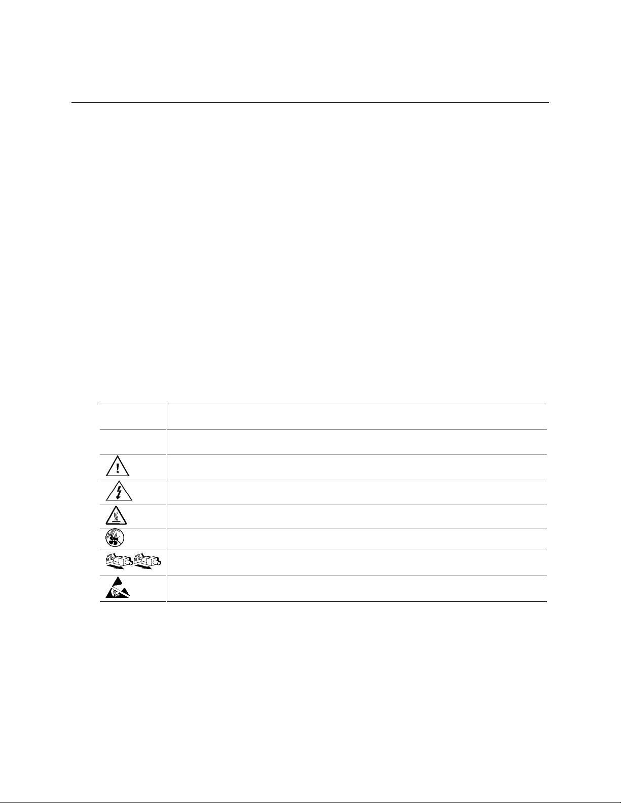
Table 1. Safety Symbols
CAUTION
WARNING
Indicates the presence of a hazard that may cause minor personal injury or property
damage if the CAUTION is ignored.
Indicates the presence of a hazard that may result in serious injury or death if the
WARNING is ignored.
Indicates potential hazard if hazard symbol is ignored.
Indicates shock hazards that result in serious injury or death if safety instructions are not
followed.
Indicates hot components or surfaces.
Indicates do not touch fan blades, may result in injury.
Indicates product has multiple power cords, and all power cords must be unplugged to
disconnect AC power or mains.
Indicates ESD sensitive components. Use of an antistatic wrist strap connected to ground is
recommended.
11
Page 12
Checking the Power Cords
WARNING
To avoid electrical shock, do not attempt to modify or use the supplied AC
power cord(s), if they are not the exact type required. If a power cord(s)
supplied is not compatible with the AC wall outlet in your region, get one
that meets the following criteria:
• The power cord must be properly rated for the AC voltage in your region.
• The power cord plug cap must have an electrical current rating that is at least
125% of the electrical current rating of the product.
• The power cord plug cap that plugs into the wall socket-outlet must have a
grounding-type male plug designed for use in your region.
• The power cord must have safety certifications for your region, and shall be
marked with the certificatio n marki ngs.
• The power cord plug cap that plugs into the AC receptacle on the power
supply must be an IEC 320, sheet C13, type female connector.
• In Europe, the power cord must be less than 4.5 meters (14.76 feet) long, and
it must be flexible <HAR> (harmonized) or VDE certified cordage to comply
with the chassis’ safety certifications.
The power supply cord(s) is the main disconnect device to AC power. The
socket outlet(s) shall be near the equipment and shall be readily accessible
for disconnection.
Multiple Power Cords
WARNING
To avoid electrical shock, disconnect all AC power cords before accessing
inside the system.
Earth Grounded Socket-Outlets
WARNING
To avoid electrical shock, the system power cord(s) must be plugged into
socket-outlet(s) that is provided with a suitable earth ground. The system will
be provided with the following marking:
Connect only to properly earthed socket outlet.
Apparaten skall anslutas till jordat uttag när den ansluts till ett nätverk.
12 Intel SPSH4 Server Platform Product Guide
Page 13

Before You Remove t he Access Cover
WARNING
To avoid personal injury or property damage, the following safety
instructions apply whenever accessing inside the prod u ct:
• Turn off all peripheral devices connected to this product.
• Turn off the system by pressing the power button on the front of the product.
• Disconnect the AC power by unplugging all AC power cords from the
system or wall outlet.
• Disconnect all cables and telecommunication lines that are connected to the
system.
• Retain all screws or other fasteners when removing access cover(s). Upon
completion of accessing inside the produ ct, ref as ten access cove r with
original screws or fasteners.
• Do not access inside power supply. There are no serviceable parts in the
power supply. Return to manufacturer fo r servicing.
Power Supply Modules
CAUTION
Power supply modules have double-pole/neutral fusing.
Fans
WARNING
To avoid injury do not contact moving fan blades.
Electrostatic Discharge (ESD)
CAUTION
Perform the procedures in this chapter only at an electrostatic discharge
(ESD) workstation, because the server components can be extremely
sensitive to ESD. If no such station is available, you can reduce the risk of
electrostatic discharge ESD damage by doing the following:
• Wear an antistatic wrist strap and attach it to a metal part of the server.
• Touch the metal on the server chassis before touching the server components.
• Keep part of your body in contact with the metal server chassis to dissipate
the static charge while handling the components.
• Avoid moving around unnecessarily.
• Hold the server components (especially boards) only by the edges.
• Place the server components on a grounded, static-free surface. Use a
conductive foam pad if available but not the component wrapper.
• Do not slide the components over any surface.
Important Safety Information 13
Page 14

Cooling and Airflow
CAUTION
For proper cooling and airflow, always install all access covers before
turning on the system. Operating the system for longer than five minutes
without the covers in place can cause overheating and damage to system
components.
Lifting and Moving
CAUTION
Do not attempt to lift or move the server by the handles on the power
supplies.
Equipment Rack Precautions
Follow the rack manufacturer’s safety and installation instructions for proper rack installation.
The following additional rack safety installation measures shall be considered:
ANCHOR THE EQUIPMENT RACK
The equipment rack must be anchored to an unmovable suitable support to
prevent the rack from falling over when one or more systems are fully
extended out of the rack assembly. You must also consider the weight of any
other devices installed in the rack assembly. The equipment rack must be
installed according to the manufa ctu rer's instructions.
MAIN AC POWER DISCONNECT
You are responsible for installing an AC power disconnect for the entire rack
unit. This main disconnect must be readily accessible, and it must be labeled
as controlling power to the entire unit, not just to the sy ste m(s).
GROUNDING THE RACK INSTALLATION
To avoid the potential for an electrical shock hazard, the rack assembly itself
must be suitably earth grounded, according to your local regional electrical
codes. This typically will require the rack to have its own separate earth
ground. We recommend you consult your local approv ed electrici an.
14 Intel SPSH4 Server Platform Product Guide
Page 15

OVER CURRENT PROTECTION
The system is designed to operate on a 20A AC voltage source that is
provided with 20A over current protection. If the AC source for the rack
exceeds 20A over current protection, each system must be provided with
20A or less over current supplemental protection. The supplementary over
current protection must have the appropriate regional safety certifications for
the over current application.
TEMPERATURE LIMITS
The operating temperature of the system, when installed in the rack, must not
go below 10 °C (50 °F) or rise above 35 °C (95 °F). Extreme fluctuations in
temperature may cause a variety of problems in system, and safety limits
may be broken.
VENTILATION CONSIDERATIONS
The equipment rack must provide sufficient airflow to the front of the system
to maintain proper cooling. The rack selected and the ventilation provided
must be suitable to the environment in which the system will be used.
Important Set-Up Safety Information
WARNING: ENGLISH (US)
AVERTISSEMENT: FRANÇAIS
WARNUNG: DEUTSCH
AVVERTENZA: ITALIANO
ADVERTENCIAS: ESPAÑOL
Important Safety Information 15
Page 16
WARNING: English (US)
The power supply in this product contains no user-serviceable parts. There may be more than
one supply in this product. Refer servicing only to qualified personnel.
Do not attempt to modify or use the supplied AC power cord if it is not the exact type required.
A product with more than one power supply will have a separate AC power cord for each
supply.
The power but ton on the system does not turn off system AC power. To remove AC power
from the syste m, you must unplug each AC power cord from the wall outlet or power supply.
The power cord(s) is considered the disconnect device to the mains (AC) power. The socket
outlet that the system p lugs into shall be installed near the equipment and shall be easily
accessible.
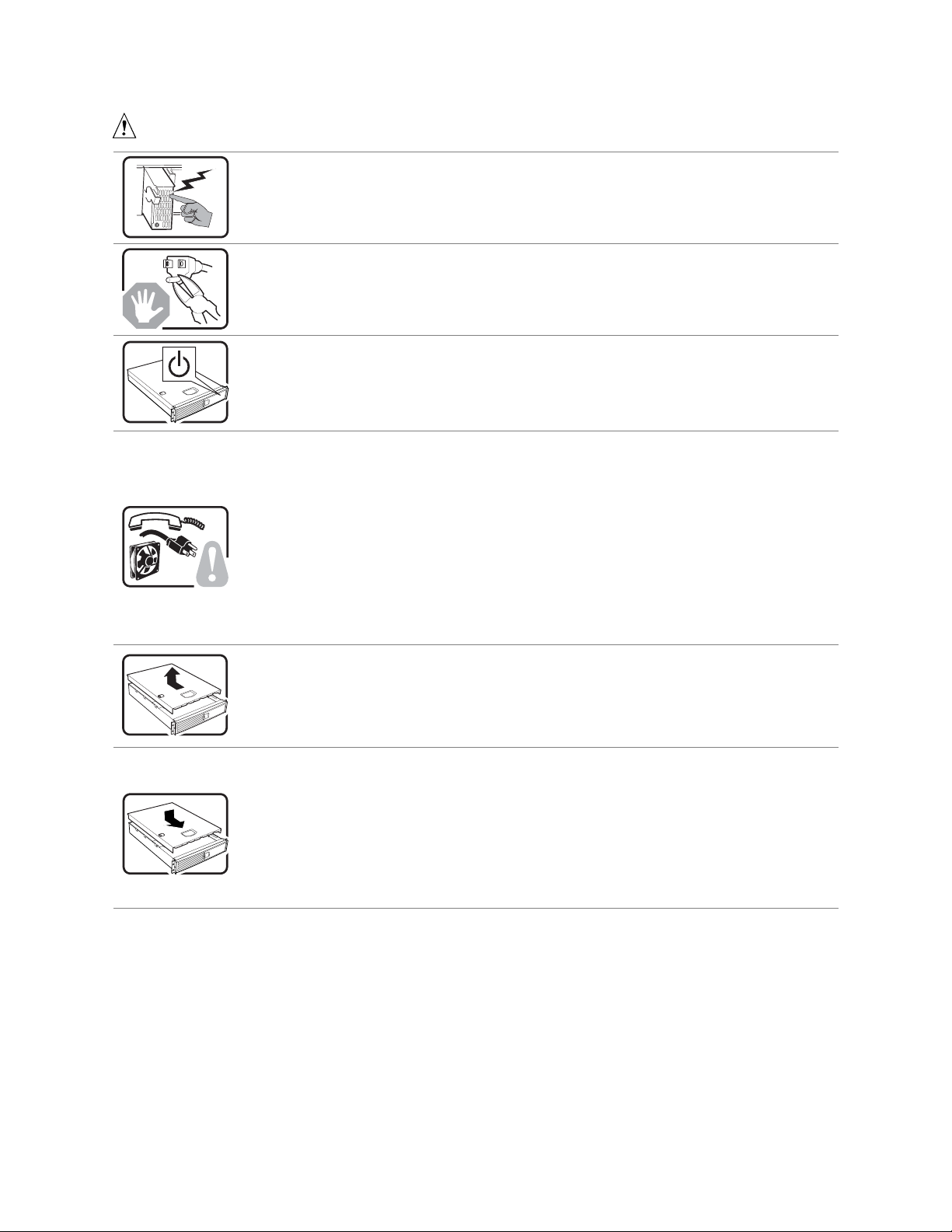
SAFETY STEPS: Whenever you remove the chassis covers to access the inside of the
system, follow these steps:
1. Turn off all peripheral devices connected to the system.
2. Turn o ff the system by pressing the power button.
3. Unplug all AC power cords from the system or from wall outlets.
4. Label and disconnect all cables connected to I/O connectors or ports on the back of the
system.
5. Provide some electrostatic discharge (ESD) protection by wearing an antistatic wrist strap
attached to chassis ground of the system—any unpainted metal surface—when handling
components.
6. Do not operate the system with the chassis covers removed.
After you have completed the six SAFETY steps above, you can remove the system covers.
To do this:
1. Unlock and remove the padlock from the back of the system if a padlock has been installed.
2. Remove and save all screws from the covers.
3. Remove the covers.
For proper cooling and airflow, always reinstall the chassis covers before turning on the
system. Operating the system without the covers in place can damage syste m parts. To
install the covers:
1. Check first to make sure you have not left loose tools or parts insi de the system.
2. Check that cables, add-in boards, and other components are properly installed.
3. Attach the covers to the chassis with the screws removed earlier, and tighten them firmly.
4. Insert and lock the pa dlock to the system to prevent unauthorized access inside the system.
5. Connect all external cables and the AC power cord(s) to the system.
continued
16 Intel SPSH4 Server Platform Product Guide
Page 17

WARNING: English (US) (Continued)
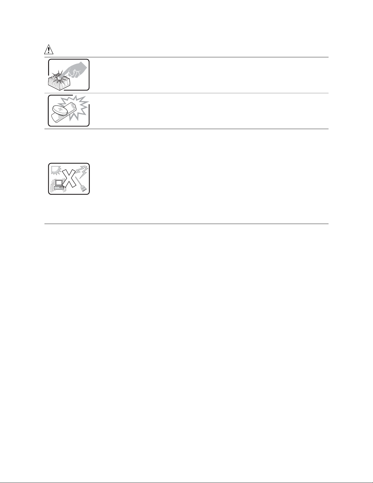
A microprocessor and heat sink may be hot if the system has been running. Also, there may
be sharp pins and edges on some board and chassis parts. Contact should be made with
care. Consider wearing protective gloves.
Danger of explosion if the battery is incorrectly replaced. Replace only with the same or
equivalent type recommended by the equipment manufacturer. Dispose of used batteries
according to manufacturer’s instructions.
The system is designed to operate in a typical office environment. Choose a site that is:
• Clean and free of airborne particles (other than normal room dust).
• Well ventilated and away from sources of heat including direct sunlight.
• Away from sources of vibration or physical shock.
• Isolated from strong electromagnetic fields produced by electrical devices.
• In regions that are susceptible to electrical storms, we recommend you plug your system
into a surge suppresser and disconnect telecommunication lines to your modem during an
electrical storm.
• Provided with a properly grounded wall outlet.
• Provided with sufficient space to access the power supply cord(s), because they serve as
the product’s main power disconnect.
Important Safety Information 17
Page 18

AVERTISSEMENT: Français
Le bloc d'alimentation de ce produit ne contient aucune pièce pouvant être réparée par
l'utilisateur. Ce produit peut contenir plus d'un bloc d'alimentation. Veuillez contacter un
technicien qualifié en cas de problème.
Ne pas essayer d'utiliser ni modifier le câble d'alimentation CA fourni, s'il ne correspond pas
exactement au type requis. Le nombre de câbles d'alimentation CA fournis correspond au
nombre de blocs d'alimentation du produit.
Notez que le commutateur CC de mise sous tension /hors tension du panneau avant n'éteint
pas l'alimentation CA du système. Pour mettre le système hors tensio n, vous devez
débrancher chaque câble d'alimentation de sa prise.
CONSIGNES DE SÉCURITÉ -Lorsque vous ouvrez le boîtier pour accéder à l’intérieur du
système, suivez les consignes suivantes:
1. Mettez hors tension tous les périphériques connectés au système.
2. Mettez le système hors tension en mettant l’interrupteur général en position OFF (boutonpoussoir).
3. Débranchez tous les cordons d’alimentation c.a. du système et des prises murales.
4. Identifiez et débranchez tous les câbles reliés aux connecteurs d’E-S ou aux accès derrière
le système.
5. Pour prévenir les décharges électrostatiques lorsque vous touchez aux composants, portez
une bande antistatique pour poignet et reliez-la à la masse du système (toute surface
métallique non peinte du boîtier).
6. Ne faites pas fonctionner le système tandis que le boîtier est ouvert.
Une fois TOUTES les étapes précédentes accomplies, vous pouvez retirer les panneaux du
système. Procédez comme suit:
1. Si un cadenas a été installé sur à l’arrière du système, déverrouillez-le et retirez-le.
2. Retirez toutes les vis des panneaux et mettez-les dans un endroit sûr.
3. Retirez les panneaux.
Afin de permettre le re froidissement et l’aérat ion du système, réinstallez toujours les panneaux
du boîtier avant de mettre le système sous tension. Le foncti onnement du système en
l’absence des panneaux risque d’endommager ses pièces. Pour installer les panneaux,
procédez comme suit:
1. Assurez-vous de ne pas avoir oublié d’outils ou de pièces démontées dans le système.
2. Assurez-vous que les câbles, les cartes d’extension et les autres composants sont bien
installés.
3. Revissez solidement les panneaux du boîtier avec les vis retirées plus tôt.
4. Remettez le cadenas en place et verrouillez-le afin de prévenir tout accès non autorisé à
l’intérieur du système.
5. Rebranchez tous les cordons d’alimentation c. a. et câbles externes au système.
Suite
18 Intel SPSH4 Server Platform Product Guide
Page 19
AVERTISSEMENT: Français (Suite)
Le microprocesseur et le dissipateur de chaleur peuvent être chauds si le système a été sous
tension. Faites également attention aux broches aiguës des cartes et aux bords tranchants du
capot. Nous vous recommandons l'usage de gants de protection.
Danger d'explosion si la batterie n'est pas remontée correctement. Remplacer uniquement
avec une batterie du même type ou d'un type équivalent recommandé par le fabricant.
Disposez des piles usées selon les instructions du fabricant.
Le système a été conçu pour fonctionner dans u n cadre de travail normal. L'emplacement
choisi doit être:
• Propre et dépourvu de poussière en suspension (sauf la poussière normale).
• Bien aéré et loin des sources de chaleur, y compris du soleil direct.
• A l'abri des chocs et des sources de vibrations.
• Isolé de forts champs électromagnétiques géenérés par des appareils électriques.
• Dans les régions sujettes aux orages magnétiques il est recomandé de brancher votre
système à un supresseur de surtension, et de débrancher toutes les lignes de
télécommunications de votre modem durant un orage.
• Muni d'une prise murale correctement mise à la terre.
• Suffisamment spacieux pour vous permettre d'accéder aux câbles d'alimentation (ceux-ci
étant le seul moyen de mettre le système hors tension).
Important Safety Information 19
Page 20

WARNUNG: Deutsch
Benutzer können am Netzgerät dieses Produkts keine Reparaturen vornehmen. Das
Produkt enthält möglicherweise mehrere Netzgeräte. Wartungsarbeiten müssen von
qualifizierten Technikern ausgeführt werden.
Versuchen Sie nicht, das mitgelieferte Netzkabel zu ändern oder zu verwenden, wenn es
sich nicht genau um den erforderlichen Typ handelt. Ein Produkt mit mehreren Netzgeräten
hat für jedes Netzgerät ein eigenes Netzkabel.
Der Wechselstrom des Systems wird durch den Ein-/Aus-Schalter für Gleichstrom nicht
ausgeschaltet. Ziehen Sie jedes Wechselstrom-Netzkabel aus der Steckdose bzw. dem
Netzgerät, um den Stromanschluß des Systems zu unterbrechen.
SICHERHEISMASSNAHMEN: Immer wenn Sie die Gehäuseabdeckung abnehmen um an
das Systeminnere zu gelangen, sollten Sie folgende Schritte beachten:
1. Schalten Sie alle an Ihr System angeschlossenen Peripheriegeräte aus.
2. Schalten Sie das System mit dem Hauptschalter aus.
3. Ziehen Sie den Stromanschlußstecker Ihres Systems aus der Steckdose.
4. Auf der Rückseite des Systems beschriften und ziehe n Sie alle Anschlußkabel von den
I/O Anschlüssen oder Ports ab.
5. Tragen Sie ein geerdetes Antistatik Gelenkband, um elektrostatische Ladungen (ESD)
über blanke Metallstellen bei der Handhabung der Komponenten zu vermeiden.
6. Schalten Sie das System niemals ohne ordnungsgemäß montiertes Gehäuse ein.
Nachdem Sie die oben erwähnten ersten sechs SICHERHEITSSCHRITTE durchgeführt
haben, können Sie die Abdeckung abnehmen, indem Sie:
1. Öffnen und entfernen Sie die Verschlußeinrichtung (Padlock) auf der Rückseite des
Systems, falls eine Verschlußeinrichtung installiert ist.
2. Entfernen Sie alle Schrauben der Gehäuseabdeckung.
3. Nehmen Sie die Abdeckung ab.
Zur ordnungsgemäßen Kühlung und Lüftung muß die Gehäuseabdeckung immer wieder vor
dem Einschalten installiert werden. Ein Betrieb des Systems ohne angebrachte Abdeckung
kann Ihrem System oder Teile darin beschädigen. Um die Abdeckung wieder anzubringen:
1. Vergewissern Sie sich, daß Sie keine Werkzeuge oder Teile im Innern des Systems
zurückgelassen haben.
2. Überprüfen Sie alle Kabel, Zusatzkarten und andere Komponenten auf ordnungsgemäßen
Sitz und Installation.
3. Bringen Sie die Abdeckungen wieder am Gehäuse an, indem Sie die zuvor gelösten
Schrauben wieder anbringen. Ziehen Sie diese gut an.
4. Bringen Sie die Verschlußeinrichtung (Padlock) wieder an und schließen Sie diese, um
ein unerlaubtes Öffnen des Systems zu verhindern.
5. Schließen Sie alle externen Kabel und den AC Stromanschlußstecker Ihres Systems
wieder an.
Fortsetzung
20 Intel SPSH4 Server Platform Product Guide
Page 21
WARNUNG: Deutsch (Fortsetzung)
Der Mikroprozessor und der Kühler sind möglicherweise erhitzt, wenn das System in Betrieb
ist. Außerdem können einige Platinen und Gehäuseteile scharfe Spitzen und Kanten
aufweisen. Arbeiten an Platinen und Gehäuse sollten vorsichtig ausgeführt werden. Sie
sollten Schutzhandschuhe tragen.
Bei falschem Einsetzen einer neuen Batterie besteht Explosionsgefahr. Die Batterie darf nur
durch denselben oder einen entsprechenden, vom Hersteller empfohlenen Batterietyp
ersetzt werden. Entsorgen Sie verbrauchte Batterien den Anweisungen des Herstellers
entsprechend.
Das System wurde für den Betrieb in einer normalen Büroumgebung entwickelt. Der
Standort sollte:
• sauber und staubfrei sein (Hausstaub ausgenommen);
• gut gelüftet und keinen Heizquellen ausgesetzt sein (einschließlich direkter
Sonneneinstrahlung);
• keinen Erschütterungen ausgesetzt sein;
• keine starken, von elektrischen Geräten erzeugten elektromagnetischen Felder
aufweisen;
• in Regionen, in denen elektrische Stürme auftreten, mit einem Überspannungsschutzgerät
verbunden sein; während eines elektrischen Sturms sollte keine Verbindung der
Telekommunikationsleitungen mit dem Modem bestehen;
• mit einer geerdeten Wechselstromsteckdose ausgerüstet sein;
• über ausreichend Platz verfügen, um Zugang zu den Netzkabeln zu gewährleisten, da der
Stromanschluß des Produkts hauptsächlich über die Kabel unterbrochen wird.
Important Safety Information 21
Page 22

AVVERTENZA: Italiano
Rivolgersi ad un tecnico specializzato per la riparazione dei componenti dell’alimentazione di
questo prodotto. È possibile che il prodotto disponga di più fonti di alimentazione.
Non modificare o utilizzare il cavo di alimentazione in c.a. fornito dal produttore, se non
corrisponde esattamente al tipo richiesto. Ad ogni fonte di alimentazione corrisponde un
cavo di alimentazione in c.a. separato.
L’interruttore attivato/disattivato nel pannello anteriore non interrompe l’alimentazione in c.a.
del sistema. Per interromperla, è necessario scollegare tutti i cavi di alimentazione in c.a.
dalle prese a muro o dall’alimentazione di corrente.
PASSI DI SICUREZZA: Qualora si rimuovano le coperture del telaio per accedere all’interno
del sistema, seguire i seguenti passi:
1. Spegnere tutti i dispositivi periferici collegati al sistema.
2. Spegnere il sistema, usando il pulsante spento/acceso dell’interruttore del sistema.
3. Togliere tutte le spine dei cavi del sistema dalle prese elettriche.
4. Identificare e sconnettere tutti i cavi attaccati ai collegamenti I/O od alle prese installate
sul retro del sistema.
5. Qualora si tocchino i componenti, proteggersi dallo scarico elettrostatico (SES), portando
un cinghia anti-statica da polso che è attaccata alla presa a terra del telaio del sistema –
qualsiasi superficie non dipinta – .
6. Non far operare il sistema quando il telaio è senza le coperture.
Dopo aver seguito i sei passi di SICUREZZA sopracitati, togliere le coperture del telaio del
sistema come seque:
1. Aprire e rimuovere il lucchetto dal retro del sistema qualora ve ne fosse uno installato.
2. Togliere e mettere in un posto sicuro tutte le viti delle coperture.
3. Togliere le coperture.
Per il giusto flusso dell’aria e raffreddamento del sistema, rimettere sempre le coperture del
telaio prima di riaccendere il sistema. Operare il sistema senza le coperture al loro proprio
posto potrebbe danneggiare i componenti del sistema. Per rimettere le coperture del telaio:
1. Controllare prima che non si siano lasciati degli attrezzi o dei componenti dentro il
sistema.
2. Controllare che i cavi, dei supporti aggiuntivi ed altri componenti siano stati installati
appropriatamente.
3. Attaccare le coperture al telaio con le viti tolte in precedenza e avvitarle strettamente.
4. Inserire e chiudere a chiave il lucchetto sul retro del sistema per impedire l’accesso non
autorizzato al sistema.
5. Ricollegare tutti i cavi esterni e le prolunghe AC del sistema.
continua
22 Intel SPSH4 Server Platform Product Guide
Page 23

AVVERTENZA: Italiano (Continua)
Se il sistema è stato a lungo in funzione, il microprocessore e il dissipatore di calore
potrebbero essere surriscaldati. Fare attenzione alla presenza di piedini appuntiti e parti
taglienti sulle schede e sul telaio. È consigliabile l'uso di guanti di protezione.
Esiste il pericolo di un esplosione se la pila non viene sostituita in modo corretto. Utilizzare
solo pile uguali o di tipo equivalente a quelle consigliate dal produttore. Per disfarsi delle pile
usate, seguire le istruzioni del produttore.
Il sistema è progettato per funzionare in un ambiente di lavoro tipo. Scegliere una
postazione che sia:
• Pulita e libera da particelle in sospensione (a parte la normale polvere presente
nell'ambiente).
• Ben ventilata e lontana da fonti di calore, compresa la luce solare diretta.
• Al riparo da urti e lontana da fonti di vibrazione.
• Isolata dai forti campi magnetici prodotti da dispositivi elettrici.
• In aree soggette a temporali, è consigliabile collegare il sistema ad un limitatore di
corrente. In caso di temporali, scollegare le linee di comunicazione dal modem.
• Dotata di una presa a muro correttamente installata.
• Dotata di spazio sufficiente ad accedere ai cavi di alimentazione, i quali rappresentano il
mezzo principale di scollegamento del sistema.
Important Safety Information 23
Page 24

ADVERTENCIAS: Español
El usuario debe abstenerse de manipular los componentes de la fuente de alimentación de
este producto, cuya reparación debe dejarse exclusivamente en manos de personal técnico
especializado. Puede que este producto disponga de más de una fuente de alimentación.
No intente modificar ni usar el cable de alimentación de corriente alterna, si no corresponde
exactamente con el tipo requerido.
El número de cables suministrados se corresponden con el número de fuentes de
alimentación de corriente alterna que tenga el producto.
Nótese que el interruptor activado/desactivado en el panel frontal no desconecta la corriente
alterna del sistema. Para desconectarla, deberá desenchufar todos los cables de corriente
alterna de la pared o desconectar la fuente de alimentación.
INSTRUCCIONES DE SEGURIDAD: Cuando extraiga la tapa del chasis para acceder al
interior del sistema, siga las siguientes instrucciones:
1. Apague todos los dispositivos periféricos conectados al sistema.
2. Apague el sistema presionando el interruptor encendido/apagado.
3. Desconecte todos los cables de alimentación CA del sistema o de las tomas de corriente
alterna.
4. Identifique y desconecte todos los cables enchufados a los conectores E/S o a los
puertos situados en la parte posterior del sistema.
5. Cuando manipule los componentes, es importante protegerse contra la descarga
electrostática (ESD). Puede hacerlo si utiliza una muñequera antiestática sujetada a la
toma de tierra del chasis — o a cualquier tipo de superficie de metal sin pintar.
6. No ponga en marcha el sistema si se han extraído las tapas del chasis.
Después de completar las seis instrucciones de SEGURIDAD mencionadas, ya puede
extraer las tapas del sistema. Para ello:
1. Desbloquee y extraiga el bloqueo de seguridad de la parte posterior del sistema, si se ha
instalado uno.
2. Extraiga y guarde todos los tornillos de las tapas.
3. Extraiga las tapas.
Para obtener un enfriamiento y un flujo de aire adecuados, reinstale siempre las tapas del
chasis antes de poner en marcha el sistema. Si pone en funcionamiento el sistema sin las
tapas bien colocadas puede dañar los componentes del sistema. Para instalar las tapas:
1. Asegúrese primero de no haber dejado herramientas o componentes sueltos dentro del
sistema.
2. Compruebe que los cables, las placas adicionales y otros componentes se hayan
instalado correctamente.
3. Incorpore las tapas al chasis mediante los tornillos extraídos anteriormente, tensándolos
firmemente.
4. Inserte el bloqueo de seguridad en el sistema y bloquéelo para impedir que pueda
accederse al mismo sin autorización.
5. Conecte todos los cables externos y los cables de alimentación CA al sistema.
continuación
24 Intel SPSH4 Server Platform Product Guide
Page 25

ADVERTENCIAS: Español (Continuación)
Si el sistema ha estado en funcionamiento, el microprocesador y el disipador de calor
pueden estar aún calientes. También conviene tener en cuenta que en el chasis o en el
tablero puede haber piezas cortantes o punzantes. Por ello, se recomienda precaución y el
uso de guantes protectores.
Existe peligro de explosión si la pila no se cambia de forma adecuada. Utilice solamente
pilas iguales o del mismo tipo que las recomendadas por el fabricante del equipo. Para
deshacerse de las pilas usadas, siga igualmente las instrucciones del fabricante.
El sistema está diseñado para funcionar en un entorno de trabajo normal. Escoja un lugar:
• Limpio y libre de partículas en suspensión (salvo el polvo normal).
• Bien ventilado y alejado de fuentes de calor, incluida la luz solar directa.
• Alejado de fuentes de vibración.
• Aislado de campos electromagnéticos fuertes producidos por dispositivos eléctricos.
• En regiones con frecuentes tormentas eléctricas, se recomienda conectar su sistema a un
eliminador de sobrevoltage y desconectar el módem de las líneas de telecomunicación
durante las tormentas.
• Provisto de una toma de tierra correctamente instalada.
• Provisto de espacio suficiente como para acceder a los cables de alimentación, ya que
éstos hacen de medio principal de desconexión del sistema.
Important Safety Information 25
Page 26

26 Intel SPSH4 Server Platform Product Guide
Page 27

2 Unpacking and Inspecting
Checking for Damage to the Packaging
Inspect the packaging container for evidence of mishandling during transit. If the packaging
container is damaged, photograph it for reference. Save the packaging container and packing
materials in the event you need to package the server for reshipment.
Checking the Package Contents
Remove the server from the packaging container and, using the list below, check that all parts and
accessories are included. Inspect the server and accessories for damage. If any of the contents
appear damaged, file a damage claim with the carrier immediately.
• Intel
• Quick Start Guide (fold-out poster)
• System Accessory Kit
®
SPSH4 Server Platform with the following parts installed:
SSH4 baseboard
SSH4 processor board
SSH4 memory board
Fan distribution board
Front panel board
Hot plug indicator board
Power distribution board
Two 600-W power supplies
Four fan modules
3.5-inch floppy drive
5.25-inch CD-ROM drive
1-inch hard disk drive bay
Bezel and either handles fo r rack moun ting or fee t for pedesta l mounting
Additional parts or components depending on specific system configuration. See system
specific documentation for a list of additio nal par ts.
Two North American power cords
SPSH4 Server Platform System Resource CD (contains product documentation, device
drivers, and software utilities)
Three sets (six rails) 5.25- in ch periph eral rai ls and scr ews
27
Page 28

28 Intel SPSH4 Server Platform Product Guide 29
Page 29
3 Getting Started
This section discusses the main steps you need to perform to get your server up and runn ing :
1. Select an appropriate site.
2. Install processors, memory, hard disk drives, and other options.
3. Connect the monitor, keyboard, and mouse.
4. Turn on the server and boot to the System Resource CD-ROM.
5. Configure the system with the FRU/SDR load utility.
6. Install the service partition (optional).
7. Install an operating system.
8. Set up system security.
9. Install the server into a rack unit (rack-mount version only).
Selecting a Site
This section describes the space and power requirements and general site criteria for installing the
server.
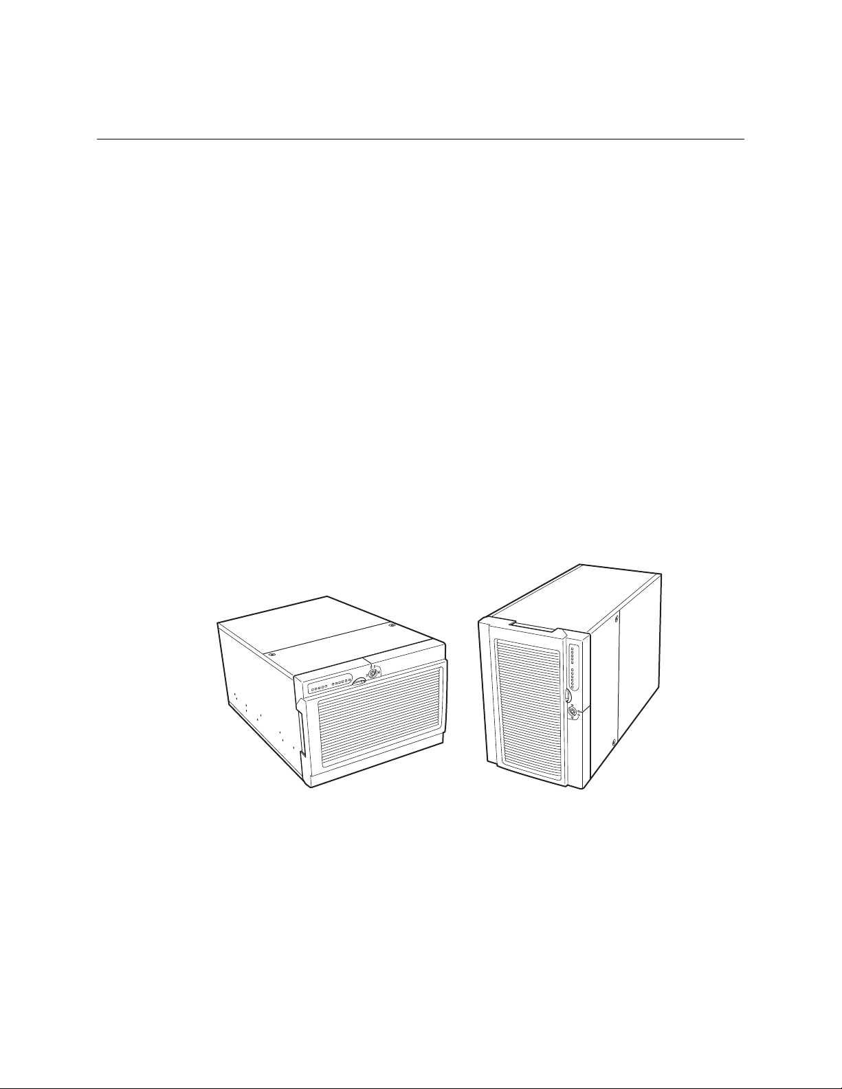
Space and Power Requirements
The server is available in both rack-mount and pedestal versions.
Figure 1. SPSH4 Server (Rack-Mount and Pedestal)
OM13380
Page 30

Table 2. SPSH4 Server Physical Specifications
Specification Rack Mount Pedestal
Height 12.25 inches (311 mm) (7U) 18.09 inches (459 mm)
Width Fits 19-inch rack 12.24 inches (311 mm)
Depth 25.25 inches (641 mm) 25.25 inches (641 mm)
Weight
Minimum configuration
Maximum configuration
Required front clearance 3 inches (76 mm), inlet airflow <35 °C
Required rear clearance 4.5 inches (114 mm), no airflow
Required side clearance 0 inch (0 mm) 0 inch (0 mm)
Power requirements
Voltage (110)
Voltage (220)
Frequency
90 pounds (41 kg)
119 pounds (57 kg)
(95 °F)
restriction
90 V
180 V
47 Hz min, 63 Hz max
* Amperage is total system power, with
two or three power suppl y modules
installed.
min, 132 V
rms
min, 264 V
rms
rms
rms
max, 9 A
rms
max, 4.5 A
96 pounds (44 kg)
125 pounds (57 kg)
12 inches (305 mm)
9 inches (229 mm)
*
90 V
*
180 V
rms
A
47 Hz min, 63 Hz max
* Amperage is total system power, with
two or three power suppl y modules
installed.
rms
min, 132 V
rms
min, 264 V
rms
*
rms
rms
max, 9 A
max, 4.5
rms
*
For detailed information on calculating power consumption for specific server configurations, see
page 163.
General Site Criteria
The server operates reliably within normal office environmental limits. Select a site that meets
these criteria:
• Near a properly grounded, three-pronged power outlet.
In the United States and Canada: a NEMA 6-15R outlet for 100-120 V and for 200-240 V.
In other geographic areas: a properly grounded outlet in accordance with the local
electrical authorities and electrical code of the region.
• Clean and relatively free of excess dust.
• Well ventilated and away from sources of heat, with the ventilating openings on the server kept
free of obstructions.
• Maximum ambient air temperature should not exceed 35 °C (95 °F).
• Away from sources of vibration or physical shock.
• Isolated from strong electromagnetic fields and noise caused by electrical devices such as
elevators, copy machines, air conditi one rs, larg e fans, large ele ct ri c moto rs, rad io and TV
transmitters, and high-frequency security devices.
• Access space provided so the server power cords can be unplugged from the power supply or
the wall outlet; this is the only way to remove AC power from the server.
• Clearance provided for cooling and airflow.
30 Intel SPSH4 Server Platform Product Guide
Page 31

NOTES
✏
Surge suppressor recommended: I n geograp h ic re gions tha t are
susceptible to electrical storms, Intel strongly recommends that you plug the
server into a surge suppressor.
EMI information: For information about complying with electromagnetic
interference regulations, see “Regional EMC Compliance Information” on
page 149.
Installing Processors, Memory, Hard Disk Drives, and Options
The server is shipped without processors, memory, or hard drives. To install the memory,
processors, hard drives, and other options, follow the steps shown on the Quick Start User Guide
that is included with the server. For more information on any of the steps listed on the guide, see
the references below:
1. Removing the covers:
a. Removing the rear access cover—see page 66.
b. Removing the access cover to the system boards—see page 68.
2. Removing the memory and processor boards:
a. Removing the memory board—see page 69.
b. Removing the air baffle—see page 71.
c. Removing the processor board—see page 73.
3. Installing memory and processors:
a. Installing the DIMMs in the memory board—see page 82.
b. Installing the processors on the processor board—see page 78.
4. Installing an ICMB board—follow the instructions that came with the ICMB board kit.
5. Installing the processor and memory boards:
a. Installing the processor board on the baseboard—see page 74.
b. Installing the air baffle—see page 72.
c. Installing the memory board—see page 70.
6. Installing PCI add-in cards—see page 93. For a description of the PCI slots, see Figure 28 on
page 93.
7. Installing hard disk drives—see page 85.
8. Installing an additional power supply or additional peripherals—see page 92, page 112, and any
additional documentation that came with the peripherals.
9. Installing covers:
a. Installing the access cover to the system boards—see page 68.
b. Installing the rear access cover—see page 66.
10. Configuring your system—complete the remainder of this “Getting Started” section.
Getting Started 31
Page 32

Connecting the Monitor, Keyboard, and Mouse
Connect the monitor, keyboard, and mouse to the appropriate connectors on the rear panel of the
server. See Figure 56 on page 134.
You have completed the hardware setup. The remainder of this section discusses software setup
and configuration.
Turning On the Server and Running the Power-On Self Test (POST)
Each time you start the server, the Power-On Self Test (POST) runs automatically. POST is stored
in flash memory.
To start the server, do the following:
NOTE
✏
To access certain features, such as BIOS Setup, you must press specific keys
at specific times during POST. To familiarize yourself with this procedure,
read the following instructions through completely before actually
performing them. For a summary of hot keys active during POST, see
Table 3 on page 33.
1. Make sure all external devices, such as a monitor, keyboard, and mouse, are connected.
2. If a drive protection card or diskette is present in the diskette drive, remove it.
3. Plug the video monitor power cord into the power source or wall outlet. Turn on the video
monitor.
4. Plug the AC power cords into the power connectors on the back of the chassis and into the
power source or wall outlet.
5. If the server does not turn on when you plug it into the AC outlet, press the on/off power button
on the front panel.
6. Verify that the main power LED on the front panel is lit (see Figure 55 on page 133).
7. Insert the SPSH4 Server Platform System Resource CD into the CD-ROM drive.
After a few seconds, POST begins and a splash screen is displayed (if the splash screen is
disabled in BIOS Setup, a diagnostics screen is displayed). POST discovers, configures, and
tests the processors, memory, keyboard, and most installed peripheral devices. The length of
time needed to complete POST depends on the amount of memory installed and the number of
option boards installed.
8. Shortly after the splash screen is displayed, POST displays the message “Press <F2> to enter
Setup…” at the bottom of the screen. At this point, you can press any of the keys identified
with an asterisk (*) in Table 3 on page 33, or you can do nothing and wait until the server boots
from the CD-ROM. If you enter BIOS Setup, the Service Partition, or the Adaptec
SCSISelect
9. After POST completes, the system beeps once and then searches all boot devices in the order
defined by the boot priority settings in the BIOS. The system finds, loads, and runs the limited
operating system on the System Resource CD.
†
Utility, when you exit those features, the server might reboot.
†
32 Intel SPSH4 Server Platform Product Guide
Page 33

NOTE
✏
If there is no device with a bootable operating system, the boot process
continues, the system beeps once, and the following message is displayed:
Operating System not found
If you have a device with a bootable operating system but see this message
anyway, reboot and use BIOS Setup (page 39) to make sure your boot device
settings are correct.
Hot Keys for POST
Table 3 lists the hot keys you can use during POST to access setup utilities and alter the normal
POST execution.
Table 3. Hot Keys
To Do This: Press These Keys:
Abort memory test during POST.
Resume after a POST error is displayed. (The
system pauses after displaying an error.)
Enter BIOS Setup during POST. <F2>*
Boot to the service partition. <F4>*
Boot from a network using Preboot Execution
Environment (PXE).
Remove the splash screen to view the diagnostic
messages during POST and display a menu for
selecting the boot device.
Enter the Adaptec SCSISelect Utility during POST. <Ctrl+A>*
* Press any of these keys when the prompt “Press <F2> to enter Setup…” is displayed.
<Space>
Press while BIOS is updating memory size on screen.
<F1>
<F12>*
<ESC>*
Note: Using BIOS Setup, you can enable the BootTime Diagnostic Screen, in which case POST does
not display the splash screen.
Note: If you use the displayed menu to change the
boot device, the change affects the current boot only.
Configuring the System with the FRU/SDR Load Utility
After POST completes and the system has finished booting from the System Resource CD, run the
FRU/SDR Load Utility to configure the sensor data record (SDR) and field replaceable unit (FRU)
inventory for the server. For instructions, see page 62.
NOTE
✏
When you first set up your server and any time you change the number of
processors, fans, or power supplies, you must run the FRU/SDR load utility.
Running FRU/SDR loads the sensor configuration (SDR) that is used to monitor
temperature, voltage, and other parameters. If the FRU/SDR configuration does
not match the physical configuration of the server, false errors might be
generated by sensors that don’t actually exist, and sens ors tha t do exist migh t not
be monitored.
Getting Started 33
Page 34

Installing the Service Partition (Recommended)
When you are setting up your server system, you can install a service partition on your hard drive.
®
The service partition, in conjunction with Intel
emergency remote management and remote server setup. The service partition lets you remotely
access a local partition on the server and identify and diagnose server health issues by using either a
modem or network connection. The service partition uses approximately 30 to 40 MB of hard disk
space.
NOTE
✏
Intel strongly recommends that you instal l the serv ic e part it ion befo re
installing an operating system. If you skip this step now, and later decide to
install a service partition, any operating system or other data on the drive will
be lost. For more information, see the “Service Partition” section in the
Installation Guide for Intel Server Management, which is contained on the
System Resource CD.
To create and format the service partition:
1. Boot the server to the System Resource CD.
2. From the menu, select Utilities and press the <Enter> key.
3. Select Run Service Partition Administrator and press the <Enter> key.
4. From the list of available items, select Creat e Ser vic e Part it ion -f irs t ti me.
5. Follow the instructions that appear on the screen. These instructions prompt you to reboot the
server. It will reboot from the CD-ROM.
6. After the system reboot, select the Utilities menu and press the <Enter> key.
7. Select Run Service Partition Administrator and press the <Enter> key.
8. Select Format Service Partition and Install Software.
9. Remove the System Resource CD from the CD-ROM drive and exit from the menu screen.
Server Management (ISM) software, provides
You can now install the operating system.
Installing the Operating System
The System Resource CD contains a limited operating system with enough functionality to boot the
server and to copy and use the utilities and other files from the CD. This limited operating system
is not intended to be used to run applications. To run your server and applications, you must install
the operating system of your choice on the server. Follow the installation instructions that came
with the operating system.
The System Resource CD-ROM
Earlier sections of this product guide referred to the System Resource CD-ROM. The CD contains
documentation, device drivers, utilities, Intel Server Management, and other useful information and
software. Most of the documentation is in Adobe
Adobe Acrobat Reader for viewing the files.
†
Acrobat† format (PDF) and the CD includes the
34 Intel SPSH4 Server Platform Product Guide
Page 35

You can access the CD in the following ways:
• Using a Web browser—Insert the CD in any system that has a Web browser. If the CD-ROM
drive in the system is set to autorun, the first screen from the CD user interface will be
displayed automatically; if not, open the file on the CD called welcome.htm. From the Web
interface, you can browse the contents of the CD, create driver and utility diskettes, and more.
• Viewing the file system—You can use a file system viewer, such as Windows
view the contents of the CD directly.
• Booting the server from the CD—You can boot the server from th e CD. The CD contains a
basic DOS operating system and DOS-based applications that let you create diskettes and run
utilities.
†
Explorer, to
System Security
System security features include both mechanical locks and software security.
Mechanical Locks
To help prevent unauthorized system entry or use, the bezel has a door and three-position key lock.
The bezel door provides access to the front panel buttons, the front panel USB and serial ports, the
hot-swap drive bays, and the peripheral devices. The three lock positions are:
• Locked—The bezel door can’t be opened and the bezel can’t be removed.
• Door unlocked—The bezel door can be opened, but the bezel can’t be removed.
• Unlocked—The bezel door can be opened, and the bezel can be removed.
The server includes two chassis intrusion switches: one for the front access cover and one for the
rear access cover. When opening either access cover, the switch transmits an alarm signal to the
baseboard management con tro lle r.
Server management software processes signals received from the intrusion switches. Using either
the System Setup Utility (page 50) or Intel Server Management (page 49), you can program the
system to power down or lock the keyboard in response to an intrusion.
Getting Started 35
Page 36

Software Security
Table 4 summarizes the security features provided by the BIOS to prevent unauthorized or
accidental access to the system. You can enable these featu res using the Secur ity s ection o f BIOS
Setup (page 39). Most of the features can also be enabled using the System Setup Utility (SSU)
(page 50). Additional information on passwords is pro vided fo llowing the table.
Table 4. Software Security Features
Feature Description
Secure Mode
Secure Mode Boot
Password on Boot
To enable secure mode: Set a user password.
To enter secure mode, do one of the following:
• Press the hot-key combination for secure mode. You can specify a hot-key
combination, which must consist of Ctrl+Alt plus one alphanumeric character.
• Let the inactivity timer time out. If you don’t touch the keyboard during the
time-out period, the system enters secure mode automatically. You can set the
time-out period from two minutes to 120 minutes.
• Power on or re set the system. The system automatically enters secure mode
on power up.
When the system is in secure mode:
• Onboard video is blanked, if enabled.
• Diskette drive is write protected, if enabled.
• Power, Sleep, and Reset buttons on the front panel are disabled.
• Mouse and keyboard input are ignored, except for entering a password.
• The keyboard LEDs flash.
To enable, do both of the following:
• Set a user password.
• Enable Secure Mode Boot.
To activate: Power on or reset the server.
When enabled:
• If booting from drive A:, the user must enter a password. After the user enters
the password, the system continues with the boot process. The system doesn’t
enter secure mode until activated by the hot-key or timer.
• If the system is not booting from drive A:, the system boots normally. No
password is required, and the system enters secure mode automatically.
The system boots according to the boot device priority set in BIOS Setup.
To enable, do all of the following:
• Set a user password.
• Enable Password on Boot.
• Disable Secure Mode Boot.
To activate: Power on or reset the server.
When enabled: The user must enter a password to boot the system. The system
boots according to the boot device priority set in BIOS Setup.
continued
36 Intel SPSH4 Server Platform Product Guide
Page 37

Table 4. Software Security Features (continued)
Feature
Fixed Disk Boot
Sector Write Protect
Power Switch Inhibit
Description
To enable, do the following:
• Set Fixed Disk Boot Sector to Write Protect in the Security section of BIOS
Setup.
To activate: Power on or reset the server.
When enabled: Write protects the master boot record of the IDE hard disk drive
when the system boots from drive A:. Prevents viruses from corrupting the boot
sector under DOS. Works only with IDE drives.
To enable: Enable Power Switch Inhibit.
To activate: Power on or reset the server.
When enabled: The power switch can’t be used to power off the system.
Using Passwords
Passwords are up to seven characters long; may use only the alphanumeric characters a-z, A-Z, and
0-9; and are not case sensitive.
You set administrator and user passwords in BIOS Setup and in the SSU. When you have either
password set, you must enter that password to do any of the following:
• Enter BIOS Setup and the SSU.
• Boot the server from drive A: when Secure Boot Mode is enabled.
• Boot the server when Password on Boot is enabled.
• Exit secure mode.
When you have both a user and an administrator password set, you may enter either password.
However, if you enter the user password for BIOS Setup or the SSU, you will be able to modify
only the time, date, language, user password, secure mode timer, and secure mode hot-key. To
modify any other features, you must enter the admin ist rato r passwo rd.
You can clear a password by setting it to a blank string. If you forget your passwords, you can use
the Password Clear jumper to clear the passwords on the next boot (see “Baseboard Jumpers” on
page 139).
Installing the Server in a Rack
The server mounts in a rack using a Rack Mount Kit. For information on rack mount kits and the
specifications for compatible racks, see:
http://support.intel.com/support/motherboards/server/ssh4/spsh4/compat.htm
Install the Rack Mount Kit following the instructions on the back of the Quick Start User Guide and
the instructions that came with the k it.
When installing or removing the server from the rac k, use an appropr ia te mech ani cal assis t unit to
lift and move the server.
Getting Started 37
Page 38

38 Intel SPSH4 Server Platform Product Guide 39
Page 39

4 Configuration Software and Utilities
This section describes the following software and utilities:
• BIOS Setup—for modifying server board set features, including setting time, date, and system
passwords; setting the boot device priority; configuring the diskette drive and serial ports; and
enabling the SCSI BIOS and system management features.
• SCSISelect—for configuring the onboard SCSI host adapter, including changing default
values, checking and changing SCSI device settings that might conflict with those of other
devices in the server, and performing a low-level format on SCSI devices installed in the
server.
• BIOS and firmware updates—for updating the BIOS on the system board and other system
firmware.
Additional utilities for system management are described on page 47.
BIOS Setup
Use BIOS Setup to change the system configuration defaults. You can run BIOS Setup with or
without an operating system being present. BIOS Setup stores most of the conf ig urat ion val ues in
battery-backed CMOS; the remainder are stored in flash memory. The values take effect when the
system is booted. POST uses these values to configure the hardware. If the values and the actual
hardware do not agree, POST generates an error message. You must run BIOS Setup to change the
BIOS settings from the default or current configuration.
Run BIOS Setup to modify server board set features such as:
• Defining the diskette drive
• Defining the serial ports
• Setting time and date
• Configuring hard drives
• Specifying boot device sequence
• Enabling SCSI BIOS
• Setting up system passwords
Using either BIOS Setup or the System Setup Utility (page 50), you can set up system passwords,
specify the boot device sequence, and enable some se rv er mana ge men t featu res. Both utili tie s
access the same stored configuration data for these items, and the result of making a change to these
settings using either utility is identical.
Recording BIOS Setup Settings
Record your BIOS Setup settings. If your custom values ever need restoring (after a CMOS clear,
for example), you must run BIOS Setup and enter your custom settings again. A record of any
custom settings will make this much easier.
Page 40

Clearing CMOS Memory
If you need to clear CMOS memory, you can use either of these two methods:
• Use the front panel buttons:
1. Power down the server.
2. Press the Reset button and hold it down for four seconds or more; while holding down the
reset button, press the power button.
3. Release both buttons at the same time.
• Use the CMOS Clear jumper (page 139):
1. Power down the server.
2. Install a jumper on the CMOS Clear jumper pins.
3. Boot the system.
4. Power down the system and remove the jumper from the CMOS Clear pins.
The next time the system is started following the CMOS clear, the boot process halts displaying the
message NVRAM cleared by jumper.
Using BIOS Setup
To run BIOS Setup, boot the server and press the F2 key when prompted.
Use the keys listed in Table 5 to navigate the BIOS Setup menus.
Table 5. BIOS Setup Menu Navigation
To: Press:
Get general help <F1> or <Alt+H>
Move between menus
Go to the previous item
Go to the next Item
Change the value of an item + or Select an item or display a submenu <Enter>
Leave a submenu or exit BIOS Setup <Esc>
Reset to BIOS Setup defaults <F9>
Save and exit BIOS Setup <F10>
← →
↑
↓
When an option is grayed out and not accessible, you cannot chang e or configure t he option in tha t
menu screen for one of the following reasons:
• The option is auto-configured or auto-detec ted .
• The field is informational only.
• The field is password protected and is accessible only by the User or Adminis trat or.
40 Intel SPSH4 Server Platform Product Guide
Page 41

SCSISelect
The SPSH4 server includes an onboard Adaptec SCSI controller with two SCSI channels (A
and B). The host adapter includes an onboard Adaptec SCSISelect configuration utility that allows
you to view and configure the settings of the host adapter and devices in the server.
NOTE
✏
The SCSISelect utility is only available if the onboard SCSI controller is
enabled in BIOS Setup.
When to Run SCSISelect
Use the SCSISelect utility to:
• Change default values
• Check and change SCSI device settings that might conflict with those of other devices in
the server
• Do a low-level format on SCSI devices installed in the server
Running SCSISelect
To run the SCSISelect utility:
1. During POST, press <Ctrl+A> to run the utility when this message appears on the video
monitor:
<<<Press <Ctrl><A> for SCSISelect(TM) Utility!>>>
2. When the main menu for the host adapter appears, follow the instru ctions on scre en to
configure the controller settings or format drives on each SCSI channel.
Configuration Software and Utilities 41
Page 42

Software Updates
Your system comes with preinstalled firmware for the system BIOS, baseboard management
controller (BMC), and hot-swap controller (HSC). A FRU/SDR Load Utility is included on the
System Resource CD. When updates for any of these items are available, you can download the
updates from the Intel support website:
http://support.intel.com/support/motherboards/server/ssh4/spsh4
Updates are available in two forms:
• A software update package (SUP) containing all updates (BIOS, BMC, HSC, and FRU/SDR)
• Individual files, one for each update
To use either form of update, you must create bootable diskettes. The procedure for creating
bootable diskettes is described in the following section. SUPs are discussed beginning on page 43
and individual updates are discussed beginning on page 43.
Creating Bootable Diskettes
To use diskettes for updates, you must format them as system or bootable diskettes with
†
version 6.22 or later or MS-DOS† version 6.22 or later.
Intel recommends that you create bootable diskettes by booting the target
system from the System Resource CD that accompanied the product.
However, the process for making the disket te s is the same for al l compa tib le
versions of DOS. ROM-DOS version 6.22 is included on the System
Resource CD.
✏
ROM-DOS
NOTE
To format a diskette as a bootable diskette:
1. Boot to the System Resource CD.
2. Exit from the menu to a DOS prompt.
3. Insert a diskette into the floppy drive.
4. At the DOS prompt, for an unformatted diskette, type:
format a:/s
or, for an already formatted diskette, type:
sys a:
5. Press <Enter>.
42 Intel SPSH4 Server Platform Product Guide
Page 43

Software Update Packages
A Software Update Package (SUP) contains all the necessary files to perform BIOS, BMC, HSC,
and FRU/SDR, or other software updates.
To install a Software Update Package:
1. Download the software update (page 42) along with any ReadMe, Release Notes, and other
files listed on the Web page for the update.
2. Print and read the ReadMe, Release Notes, and any other text or document files that came with
the update. The files from the Web page contain the latest information and instructions for the
update, which supercedes the information in this product guide.
3. Record the current BIOS settings.
a. Boot the computer and press <F2> when you are prompted to do so.
b. Write down the current settings in the BIOS Setup program.
4. Follow the installation instructions that came with the update.
NOTE
✏
Do not turn off the system during the update process.
5. When the update is complete, use BIOS Setup (page 39) to reconfigure any custom settings.
Individual Updates
This section gives procedures for performing individual updates of the BIOS, BMC or HSC
firmware, and FRU/SDR data.
BIOS Updates
The IFLASH utility is a DOS-based utility used to install BIOS updates. IFLASH.EXE is included
with the BIOS update file.
Updating the BIOS
To update the BIOS:
1. Download the software update (page 42) along with any ReadMe, Release Notes, and other
files listed on the Web page for the update.
2. Print and read the ReadMe, Release Notes, and any other text or document files that came with
the update. The files from the Web page contain the latest information and instructions for the
update, which supercedes the information in this product guide.
3. Record the current BIOS settings.
a. Boot the computer and press <F2> when you are prompted to do so.
b. Write down the current settings in the BIOS Setup program.
4. Follow the installation instructions that came with the update.
5. When the update is complete, use BIOS Setup (page 39) to reconfigure any custom settings.
Configuration Software and Utilities 43
Page 44

Recovering the BIOS
In the rare event that the BIOS update fails and the BIOS is corrupted, you will need to recover the
BIOS. The Release Notes or other documentation that you downloaded with the BIOS update
explain the steps for recovering the BIOS. The procedure requires you to install one or more
jumpers temporarily. For the location of the jumpers and help in identifying the correct jumper
pins, see pages 138 and 139.
Changing the BIOS Language
You can use the BIOS update utility to change the language used for text in the BIOS Setup user
interface:
1. Insert the diskette holding the BIOS update files into drive A and boot the server.
2. Follow the instructions that appear on the screen, choosing to update the language files.
3. When the utility finishes updating the BIOS, remove the diskette from drive A and reboot the
system.
Firmware Updates
The Firmware Update Utility is a DOS-based program used to update the BMC and HSC firmware
code. You need to run the utility only if new firmware code is necessary. The utility is included
with the firmware update file.
To update the firmware:
1. Download the firmware update (page 42) along with any ReadMe, Release Notes, and other
files listed on the Web page for the update.
2. Print and read the ReadMe, Release Notes, and any other text or document files that came with
the update. The files from the Web page contain the latest information and instructions for the
update, which supercedes the information in this product guide.
3. Follow the installation instructions that came with the update.
4. After the update is complete, if you are updating the BMC firmware, disconnect the AC power
cord from the system and wait 60 seconds.
NOTE
✏
To complete the update of the BMC firmware, you must disconnect the AC
power cord to remove the standby power from the BMC. Removing the
standby power forces the BMC to reset, which is necessary to complete the
update.
5. Reconnect the AC power cord and power up the system.
6. If you are updating the BMC firmware, run the FRU/SDR utility (page 62).
44 Intel SPSH4 Server Platform Product Guide
Page 45

FRU/SDR Updates
The Field Replacement Unit (FRU) and Sensor Data Record (SDR) load utility is a DOS-based
program used to update the server FRU and SDR configuration. The utility is included with the
update file.
To update the FRU/SDR configuration:
1. Download the software update (page 42) along with any ReadMe, Release Notes, and other
files listed on the Web page for the update.
2. Print and read the ReadMe, Release Notes, and any other text or document files that came with
the update. The files from the Web page contain the latest information and instructions for the
update, which supercedes the information in this product guide.
3. Follow the installation instructions that came with the update.
Configuration Software and Utilities 45
Page 46

46 Intel SPSH4 Server Platform Product Guide 47
Page 47

5 System Management
Intel integrates system management features into the hardware and provides additional features
through Intel Server Management software. This section describes the integrated hardware features,
Intel Server Management software, and the System Setup Utility and FRU/SDR Load Utility used to
configure the hardware features.
Integrated Hardware System Management
Figure 2 is a simplified diagram of the system management features integrated into the server.
Processor
Sockets
Temperature
Sensors
Front
Panel
Power
Supplies
Fans
Chassis
Intrusion
Memory
BMC
Nonvolatile storage
SEL
Figure 2. Integrated System Management
SDR FRU
EMP
LAN1
Baseboard Management Controller
Intel server boards incorporate a baseboard management controller (BMC), which is a dedicated
microcontroller for system management activities. The BMC performs the following functions:
• Monitors system components and sensors, including processors, memory, fans, power supplies,
temperature sensors, and chassis intrusion sensors.
• Manages nonvolatile storage for the system event log (SEL), sensor data records (SDRs), and
baseboard field-replaceable unit (FRU) inventory.
• Interfaces with the emergency management port (EMP) and LAN1 port to send alerts and
interact with remote management systems.
• Provides the main front panel control func ti ons (powe r on/off, res et, and so on).
Page 48

Field Replaceable Units and Sensor Data Records
Field replaceable units (FRUs) are major modules in the chassis that contain active electronic
circuitry. FRUs can store information—such as board serial number, part number, name, and asset
tag—that can be read using the System Setup Utility (page 50). The BMC stores FRU information
for the baseboard in a nonvolatile storage component on the board.
The BMC uses Sensor Data Records (SDRs) to identify the sensors in the system for monito ri ng.
SDRs provide a list of the sensors, their characteristics, location, type, and type-specific information,
such as default threshold values, facto rs for conve rt ing a sensor read ing in to the appropr ia te uni ts
(mV, rpm, degrees Celsius), and information on the types of events that a sensor can generate. The
BMC stores SDR information in a nonvolatile storage component on the baseboard.
You can use the FRU/SDR Load Utility (page 62) to initialize or update the FRU and SDR
information. Intel server boards are shipped from the factory with some sensors disabled, because
the actual configuration of the chassis is only determined when the user completes the system
configuration. Chassis-specific infor mation in the FRU, such as chassis part number, is also absent.
For these reasons, it is important to run the FRU/SDR Load Utility as part of the system setup
process. You should also run the FRU/SDR Load Utility whenever you change the number of fans,
processors, or power supplies in the server.
System Event Log
The BMC manages a system event log (SEL), where it records significant or critical system events.
Such events include temperatures and voltages out of range, fan failures, and other sensor-related
events. The BIOS, software, add-in cards, and other devices can also log events by sending
messages to the BMC. The SEL is stored in nonvolatile storage.
You can view the current contents of the SEL by using the System Setup Utility (page 50).
Platform Event Management
Events can trigger alerts and other actions by the BMC. The server is configured with the following
set of standard events:
• Temperature sensor out of range
• Voltage sensor out of range
• Fan failure
• Chassis intrusion
• Power supply fault
• BIOS uncorrectable ECC error
• BIOS POST error
• Processor fault resilient booting (FRB) failure
• Fatal nonmaskable interrupt (NMI) from a source other than the front panel switch
• Watchdog timer reset, power down, or power cycle
• System restart (reboot)
48 Intel SPSH4 Server Platform Product Guide
Page 49

Alerts can take either of these forms:
• Platform event pages—the BMC dials a paging service and sends a predefined paging string.
To use platform event paging (PEP), you must attach an external modem to the emergency
management port (COM2).
• BMC LAN alerts—the BMC sends an alert to a predefined destination on the LAN.
You can configure PEP and BMC LAN alerts by using the System Setup Utility (page 50).
Emergency Management Port
The emergency management port (EMP) refers to the use of the COM2 port, with either an external
modem or direct serial connection, for remote management. The BMC controls the port and
interfaces with remote acc e ss softw a re, such as the Direct Platform Control application in Intel
Server Management.
You can configure the EMP by using the System Setup Utility (page 50).
Intel Server Management
Intel Server Management (ISM) is a system manag em e nt package that is inc luded on the System
Resource CD or on a separate ISM CD. ISM applications interac t with the int egr ated hardware
system management feature s of the server to all ow you to monitor and manage a server fr om a
remote workstation:
• Remote connection from a Windows-based client workstation over a LAN, or over a modem or
direct serial connection to the emergency management port on the server.
• Real-time monitoring and alerting for server hardware sensors.
• Emergency management when the server is off (but still connected to AC power) lets you verify
the state of the server, diagnose hardware problems, and power on/off or reset the server.
• Run the System Setup Utility to change the server configuration.
• Run diagnostics tools similar to those used during factory testing.
ISM depends on a service partition on the server that you are managing. The service partition is a
special disk partition on the system drive that contains a ROM-DOS
DOS-based utilities, including the System Setup Utility, FRU/SDR Load Utility, and Remote
Diagnostics. The server can be booted to the service partition, either locally or remotely, to provide
access to the utilities.
For more information on Intel Server Management and the individual ISM applications, see the ISM
CD or System Resource CD.
System Management 49
†
operating system and
Page 50

Using the System Setup Utility
The System Setup Utility (SSU) is located on the System Resource CD-ROM shipped with the
server.
Run the System Setup Utility to:
• Set boot device priority
• Set passwords and security options
• View system events
• View FRU information
• View sensor data records
• Update system firmware and BIOS
• Save and restore the system configuration
• Set up the server to send alerts for platform events
• Set up the server for remote management
Using either the System Setup Utility or BIOS Setup (page 39), you can specify the boot device
sequence and set up system passwords and security options. Both utilities access the same stored
configuration data for these items, and the result of making a change to these settings using either
utility is identical.
The SSU consists of a collection of task-oriented modules plugged into a common framework called
the Application Framework (AF). The Application Framework provides a launching point for
individual tasks and a location for setting customization information.
Creating SSU Diskettes
You can run the SSU directly from the Utilities menu of the System Resource CD-ROM, from a set
of DOS diskettes, or from the service partition of the hard disk.
If you choose to run the SSU from a set of DOS diskettes, you must create the SSU diskettes from
the Resource CD-ROM as follows:
1. Boot to the System Resource CD-ROM.
2. Choose Create Diskettes > Create Diskettes by Device/Function > System Setup Utility.
3. Follow the instructions displayed.
Alternatively, if you have a workstation with the Microsoft Windows operating system, you can
insert the CD into that system and create the diskettes on that system.
50 Intel SPSH4 Server Platform Product Guide
Page 51

Running the SSU
When the SSU starts in the default local execution mode, the SSU accepts input from the keyboard
or mouse. The SSU presents a VGA-based GUI on the primary monitor.
If you run the SSU from read-only media, such as the CD-ROM, you cannot save user preference
settings (such as screen colors).
The SSU supports ROM-DOS version 6.22. The SSU will not operate from a “DOS box” running
under an operating system such as Windows.
To start the SSU:
1. Start the SSU using one of the following methods:
From diskettes: Insert the first SSU diskette in drive A and boot the server from the
diskette. You are prompted to insert the second diskette. After loading completes the SSU
starts automatically.
From the System Resource or ISM CD-ROM: Boot the server to the System Resource
CD and start the SSU from the Utilities menu.
From the Service Partition: Boot the server to the Service Partition (page 32) and execute
the following DOS commands:
C:\> cd ssu
C:\SSU> ssu.bat
2. The mouse driver loads if it is available; press <Enter> to continue.
3. When the SSU title appears on the screen, press <Enter> to continue.
Working with the GUI
You can access features of the GUI using the mouse or keyboard:
• Mouse—Click once to choose menu items and buttons or to select items in a list, such as the
Available Tasks list. To run a list item, such as one of from the Available Tasks list, select the
item and click OK or double-click the item.
• Keyboard—Use the tab and arrow keys to highlight buttons and press the spacebar or <Enter>
to execute. You can also execute a menu or button by using the <Alt> key in combination with
the underlined letter in the name of the menu or button.
You can have more than one task open at the same time, although some tasks might require complete
control to avoid possible conflicts. The tasks achieve complete control by keeping the task as the
center of operation until you close the task window.
The SSU has a build-in help system, which you access by clicking a Help button or choosing the
Help menu.
System Management 51
Page 52

Customizing the SSU Interface
The SSU lets you customize your interface using the Preferences section of the main window. The
AF sets these preferences and saves them in the AF.INI file so that they take effect the next time you
start the SSU. There are four user customizable settings:
• Color—lets you change the default colors associated with different items on the screen using
predefined color combinations. The color changes take effect immediately.
• Mode—lets you set the desired expertise level: novice, intermediate, or expert.
The expertise level determines which tasks are visible in the Available Tasks section and which
actions each task performs. For a new mode setting to take effect, you must exit the SSU and
restart it.
• Language—lets you change the text in the SSU to the appropriate language. For a new
language setting to take effect, you must exit the SSU and restart it.
• Other—lets you show or hide the status bar at the bottom of the SSU main window. The change
takes effect immediately.
NOTE
✏
If you run the SSU from read-only media (CD-ROM, for exa mpl e), the se
preferences are lost when you exit the SSU.
Exiting the SSU
Exiting the SSU closes all SSU windows.
Setting Boot Device Priority
To change the boot priority of a device:
1. From the SSU Main window, choose Boot Devices.
2. In the Multiboot Options Add-in window, select a device.
3. Click the Move Up button to move it up in the list. Click the Move Down button to move it
down.
Setting Passwor ds and Security Options
You can set a user password and an admin password. On some systems, you must set an admin
password before you can set a user password. On other systems, the passwords are independent.
You can set the same passwords and security options by using BIOS Setup (39).
Setting the Admin Password
The Admin Password button lets you set or change the admin password used by both the SSU and
the system BIOS. This option is not available if both an admin and a user password are set and you
entered only the user password when you started the SSU. All changes to the admin password take
effect immediately.
52 Intel SPSH4 Server Platform Product Guide
Page 53

To change or clear the administrator passwo rd:
1. From the SSU Main window, choose Security.
2. Click the Admin Password button.
3. If you are changing passwords, enter the old password.
4. Enter the new password (or leave blank to clear).
5. Confirm the password by entering it again (or leave blank to clear).
6. Click OK to save the password and return to the Security window.
Setting the User Password
The User Password button lets you set or change the user password used by both the SSU and the
system BIOS. All changes to the user password take effect immediately.
To change or clear the user password:
1. From the SSU Main window, choose Security.
2. Click the User Password button.
3. If you are changing passwords, enter the old password in the first box.
4. Enter the new password (or leave blank to clear).
5. Confirm the password by entering it again (or leave blank to clear).
6. Click OK to save the password and return to the Security window.
Setting Security Options
For a description of security features, see page 36.
To set the security options:
1. In the Security window, click the Options button.
2. For each option, select the desired setting from the list. The options are:
• Security Hot Key: The key combination that can be used to put the server into secure mode.
• Secure Mode Timer: If no keyboard or mouse activity occurs during the chosen time
interval, the server enters secur e mode.
• Secure Mode Boot: Enable forces the server to boot directly into secure mode.
• Video Blanking: Enable turns off the video when the server is in secur e mode.
• Floppy Write: Enable prevents writing to the diskette drive while the server is in secure
mode.
• Power Switch Inhibit: Enable prevents the power and reset buttons from functioning when
the server is in secure mode. Disable allows the power and reset buttons to function
normally when the server is in secure mode.
3. Click Save to save the settings and return to the Securi ty window.
System Management 53
Page 54

Viewing the System Event Log
To view the System Event Log (SEL):
1. From the SSU Main window, choose SEL Manager.
When you start the SEL Manager, it automatically loads the current list of events from
non-volatile memory.
2. Use the <F4> and <F5> keys to scroll the window contents to the left and right to view all of the
columns.
3. Use the File and SEL menu items to work with the SEL information:
• Open: Views data from a previously saved SEL file.
• Save As: Saves the currently loaded SEL data to a file.
• Properties: Displays information about the SEL.
• Clear SEL: Clears the SEL data from the nonvolatile storage area.
• Reload: Refreshes the display by reading the current SEL entries from the server.
• Sort By: Sorts the displayed events by event number, time stamp, sensor type and number,
event description, or event generator ID.
Viewing FRU Information
To view the Field Replaceable Unit (FRU) information:
1. From the SSU Main window, choose FRU Manager.
When you start the FRU Manager, it automatically loads the current list of events from non-
volatile memory.
The FRU Manager window has a navigation pane on the left that displays, in a tree format,
the inventory of components in the server. The tree has three categories: Chassis, Board, and
Product. Clicking on a category expands or collapses a list of components for that category.
Clicking on an individual component displays the FRU information for that component in
the presentation pane in the upper right. The description pane in the lower right displays a
description of the currently sele ct ed FRU area.
2. Use the <F4> and <F5> keys to scroll the window contents to the left and right to view all of the
columns.
3. Use the File and FRU menu items to work with the FRU information:
• Open: Views data from a previously saved FRU file.
• Save As: Saves the currently loaded FRU data to a file.
• Properties: Displays the number of FRU devices in the system and the number being
displayed. Only FRU devices with valid FRU areas are displayed.
• Reload: Refreshes the display by reading the current FRU entries from the server.
54 Intel SPSH4 Server Platform Product Guide
Page 55

Viewing Sensor Data Records
To view the Sensor Data Records (SDR):
1. From the SSU Main window, choose SDR Manager.
When you start the SDR Manager, it automatically loads the SDR entries from non-volatile
memory.
The SDR Manager window has a navigation pane on the left that displays, in a tree format,
the sensor data records. The tree has categories for each type of record. Clicking on a
category expands or collapses a list of SDRs for that category. Clicking on an individual
SDR displays the information for that SDR in the presentation pane in the upper right. The
description pane in the lower right displays a description of the currently selected SDR type.
2. Use the <F4> and <F5> keys to scroll the window contents to the left and right to view all of the
columns.
3. Use the File and SDR menu items to work with the SDR information:
• Open: Views data from a previously saved SDR file.
• Save As: Saves the currently loaded SDR data to a file.
• Properties: Displays information about the SDR, including IPMI version, number of SDR
entries, time stamps for changes to the SDR information, and free space remaining.
• Reload: Refreshes the display by reading the SDR data from the server.
Updating System Firmware and BIOS
Using the SSU, you can update the BIOS, update the firmware, and verify the firmware. Procedures
for each are given below. You can also update the BIOS and firmware without using the SSU
(page 42). You can download the updates from the Intel support website:
http://support.intel.com/support/motherboards/server/ssh4/spsh4
Updating the BIOS
To update the BIOS:
1. Download the update from the Intel support website.
2. From the SSU Main window, choose System Update. (System Update is available only in
Expert mode.)
When you start System Update, it automatically displays the current revision information for the
system firmware and BIOS.
3. From the File menu, choose Load and choose a .uif or .bio file to use for the update.
4. Click the Update button to update the BIOS.
System Management 55
Page 56

Updating the Firmware
To update the system firmware:
1. Download the update from the Intel support website.
2. From the SSU Main window, choose System Update. (System Update is available only in
Expert mode.)
3. When you start System Update, it automatically displays the current revision information for the
system firmware and BIOS.
4. From the File menu, choose Load and choose a .uif or .hex file to use for the update.
5. Click the Update button to perf or m the update .
Verifying the Firmware
To compare the system firmware in nonvolatile memory with a firmware file:
1. Download the update from the Intel support website.
2. From the SSU Main window, choose System Update. (System Update is available only in
Expert mode.)
When you start System Update, it automatically displays the current revision information for the
system firmware and BIOS.
3. From the File menu, choose Load and choose a .hex file to use for the update.
4. Click the Verify button to compare the firmware code in nonvolatile storage with the selected
file.
Saving and Restoring the System Configuration
Using the SSU, you can save the following configuration information to a file:
• Platform type, BIOS revision, and firmware revision
• CMOS settings
• Extended system configuration data (ESCD)
• Settings for the emergency management port (EMP), platform event paging (PEP), and BMC
LAN alerts
Data is saved from all sources. There is no way to choose only certain pieces of configuration data
to save. You can also restore the information from a saved configuration file.
NOTE
✏
BIOS passwords are stored in the file. Restoring a configuration can change
passwords on a server. EMP and LAN passwords are not stored in the file.
Saving a Configuration
To save the system configuration:
1. From the SSU Main window, choose Config Save/Restore. (Configuration Save/Restore is
available only in Expert mode.)
2. Click Save To File and specify a filename and location.
56 Intel SPSH4 Server Platform Product Guide
Page 57

Restoring a Configuration
To restore the system configuration from a file:
1. From the SSU Main window, choose Config Save/Restore. (Configuration Save/Restore is
available only in Expert mode.)
2. Click Restore from File and specify a filename and location.
The CSR reads the platform type, BIOS revision, and firmware revision from the file and
compares that information with the same information retrieved from the server. If the two do not
match, an error message is displayed and the restore operation aborts. If they do match, the CSR
restores the configuration data to the server. It prompts you to reboot the server for the new
settings to take effect.
Alerting for Platform Events
You can set up the server to alert you when various events occur. Alerts can be delivered either as
telephone pages or over the LAN. Instructions for setting up both telephone paging alerts and LAN
alerts are given below.
System Management 57
Page 58

Setting Up Paging Alerts
To set up the server to send alerts as telephone pages:
1. Install an external modem on the Emergency Management Port (COM2).
2. From the SSU Main window, choose Platform Event Manager (PEM).
3. In the PEM window, click Configure EMP.
4. In the corresponding boxes, enter the following command strings for the modem attached to the
EMP port:
• ESC Sequence: the escape sequence. This string is sent to the modem before sending
command strings. The maximum length for the string is five characters; longer strings are
truncated.
• Hangup String: hang up or drop the connection. The EMP automatically sends an
<ENTER> character following this string. The maximum length for the str ing is e ight
characters; longer strings are truncated.
• Modem Dial Command: the command to dial a phone number. This string is sent to the
modem before sending the paging string.
• Modem Init String: the in itial iza t ion string for the modem. This stri ng is sent e very time
the EMP initializes. The maximum length for the string is determined at run-time from
firmware. You will be notified if the string is truncated. Following a save, the actual string
saved is displayed in the edit box.
5. Click Save to save the changes.
6. Click Close to return to the PEM window.
7. In the PEM window, click Configure PEP.
8. Select the Enable PEP check box.
9. In the Blackout Period box, enter the minimum time, in minutes, between successive pages.
The valid range is [0 - 255] where 0 disables the blackout period. Setting a blackout period can
save you from being flooded with repeat pages. After you receive a PEP page, no additional
pages are sent by PEP for the duration of the blackout period.
10. In the Paging String box, enter the phone number to dial for the page and the message you want
sent with the page. The maximum length for the paging string is deter mi ned at run-t im e from
firmware. You will be notified if the string is truncated. Following a save, the actual string
saved is displayed in the edit box.
11. From the Options menu, choose Configure Event Actions.
12. In the Platform Event Paging Actions window, move the events that you want to generate an
alert to the Enabled column and move all other events to the disabled column using the following
buttons:
• >>: Moves all events from the enabled list to the disabled list.
• >: Moves the selected event from the enabled list to the disabled list.
• <: Moves the selected event from the disabled list to enabled the list.
• <<: Moves all events from the disabled list to the enabled list.
13. Click Save to save the changes.
58 Intel SPSH4 Server Platform Product Guide
Page 59

14. Click Close to return to the PEP Configuration window.
15. To send a test page to verify that you have correctly configured PEP, from the Options menu,
choose Send Alert.
16. Click Save to save the configuration.
17. Click Close to return to the Platform Event Manager window.
Setting Up LAN Alerts
To set up the server to send alerts over the LAN:
1. Configure the remote system to receive alerts. For more information, see the documentation for
Intel Server Management software.
2. From the SSU Main window, choose Platform Event Manager (PEM).
3. In the PEM window, click Configure LAN.
4. Select the Enable LAN Alerts check box.
5. (Optional) In the SNMP Community String box, enter a string for the community field in the
Header section of the SNMP trap sent for an alert. The string must be from 5 to 16 characters.
The default string is public.
6. In the IP Setup box, choose either:
• DHCP: the IP address for the server is automatically assigned by the DHCP (dynamic host
control protocol) server on the network. The Host, Gateway, and Subnet Mask boxes in the
dialog are ignored.
• Static: assign the IP address for the server using the Host, Gateway, and Subnet Mask boxes
in the dialog.
7. If you chose Static IP Setup in the previous step, fill in the IP addressing boxes:
• Host IP Address: the IP address of this server.
• Gateway IP Address: the IP address of the router for this server.
• Subnet Mask: the IP address for the server’s subnet. The server uses this to decide if the
alert destination is on the same subnet.
8. In the Alert IP Address box, fill in the IP address of the system you want to receive alerts from
this server. If you want the alert to be broadcast to an entire subnet, enter the IP address for the
subnet.
9. From the Options menu, choose Configure Event Actions.
10. In the BMC LAN Alerting Actions window, move the events that you want to generate an alert
to the Enabled column and move all other events to the disable d colum n using the following
buttons:
• >>: Moves all events from the enabled list to the disabled list.
• >: Moves the selected event from the enabled list to the disabled list.
• <: Moves the selected event from the disabled list to enabled the list.
• <<: Moves all events from the disabled list to the enabled list.
11. Click Save to save the changes.
12. Click Close to return to the BMC LAN Configuration window.
System Management 59
Page 60

13. To send a test alert to verify that you have correctly configured BMC LAN alerts, from the
Options menu, choose Send Alert.
14. Click Save to save the changes.
15. Click Close to return to the PEM window.
Managing the Server Remotely
You can set up the server so that you can connect to it from a remote client system to perform
management tasks. You can make the connection over a LAN or by using a modem or direct serial
cable to the Emergency Management Port (EMP). Instructions for setting up the server for remote
LAN and serial/modem access are given below.
Setting Up Remote LAN Access
To configure remote LAN access:
1. From the SSU Main window, choose Platform Event Manager (PEM).
2. In the PEM window, click Configure LAN.
3. If you want to require a password for remote access, enter the pas sword in the Enter New
Password box and in the Verify New Password box. Passwords can be from 1 to 16 characters
long, using any ASCII character in the range [32-126]. To clear the passwords, leave both boxes
blank. (You can also clear the password by choose the menu Options > Clear LAN Password.)
4. From the LAN Access Mode list, select the remote access mode:
• Full Access: a remote system can initiate a LAN connection regardless of the state or health
of the server.
• Restricted: a remote system can initiate a LAN connection, but cannot perform control
operations such as power down, reset, or front panel NMI.
• Disabled: remote systems are not allowed to initiate LAN connections.
5. In the IP Setup box, choose either:
• DHCP: the IP address for the server is automatically assigned by the DHCP (dynamic host
control protocol) server on the network. The Host, Gateway, and Subnet Mask boxes in the
dialog are ignored.
• Static: assign the IP address for the server using the Host, Gateway, and Subnet Mask boxes
in the dialog.
6. If you chose Static IP Setup in the previous step, fill in the IP addressing boxes:
• Host IP Address: the IP address of this server.
• Gateway IP Address: the IP address of the router for this server.
• Subnet Mask: the IP address for the server’s subnet. The server uses this to decide if the
alert destination is on the same subnet.
7. Click Save to save the changes.
8. Click Close to return to the PEM window.
60 Intel SPSH4 Server Platform Product Guide
Page 61

Setting Up Remote Modem or Serial Access
To configure remote modem or serial access:
1. From the SSU Main window, choose Platform Event Manager (PEM).
2. In the PEM window, click Configure EMP.
3. If you want to require a password for remote access, enter the pas sword in the Enter New
Password box and in the Verify New Password box. Passwords can be from 1 to 16 characters
long, using any ASCII character in the range [32-126]. To clear the passwords, leave both boxes
blank. (You can also clear the password by choose the menu Options > Clear LAN Password.)
4. In the Modem Ring Time box, enter the number of 500ms intervals that the BMC should wait
before taking control of the COM2 port and answering an incoming call. A value greater than
zero gives the BIOS time to answer before the BMC takes control. A value of zero causes the
BMC to answer immediately. The maximum value, 63, tells the BMC to ignore the call.
Modem Ring Time applies only to Preboot access mode and is ignored for other access modes.
5. In the System Phone Number box, enter the number for the phone line connected to the modem
on the EMP.
6. From the Access Mode list, choose the remote access mode:
• Always Active: the EMP is available at any time.
• Preboot: the EMP is available only when the server is powered down or is in the running
POST during startup.
• Disabled: remote systems are not allowed to initiate connections.
7. From the R est ricted Mode list, choose either:
• Enabled: a remote system can initiate a connection, but cannot perform control operations
such as power down, reset, or front panel NMI.
• Disabled: the remote system has full control of the server.
8. From the Connection Mode list, choose either:
• Direct Connect: the COM2 port on the server is connected by a serial cable to the remote
system.
• Modem Connect: the COM2 port on the server is connected to a modem.
9. Click Save to save the changes.
10. Click Close to return to the PEM window.
System Management 61
Page 62

FRU/SDR Load Utility
The Field Replacement Unit (FRU) and Sensor Data Record (SDR) load utility is a DOS-based
program used to update the server management subsystem’s product level FRU and SDR nonvolatile
storage. The utility:
• Discovers the product configuration based on instructions in a master configuration file
• Displays the FRU, SDR, and SMB information
• Updates the nonvolatile storage managed by the BMC that holds the SDR and FRU area
• Generically handles FRU devices that might not be associated with the BMC
When to Run the FRU/SDR Load Utility
You’ll need to run the FRU/SDR utility in these situations:
• When first setting up your server
• Whenever you change the number of power supplies, processors, or fans in the server
• When installing a FRU/SDR update (page 45)
NOTE
✏
If the FRU/SDR configuration information in BMC nonvolatile storage does
not match the physical configuration of the server, you might see false errors
generated by sensors that don’t actually exist, and sens ors tha t do exist migh t
not be monitored. So, it’s important to keep the configuration up to date.
Running the FRU/SDR Load Utility
You can run the utility directly from the Utilities menu of the System Resource CD. However, if
you have downloaded an update, you should run the updated version from the update diskette.
The executable file for the utility is FRUSDR.EXE. The utility requires the following:
• ROM-DOS version 6.22 or MS-DOS version 6.22 (and later versions)
• One or more .fru files describing the system’s field replaceable units
• A .cfg file describing the system configuration
• An .sdr file describing the sensors in the system
62 Intel SPSH4 Server Platform Product Guide
Page 63

Command Line Format
The basic command line format is:
FRUSDR [-?] [-h] [-d {fru, sdr, smb}] [-cfg filename.cfg] [-fru filename.fru]
Table 6. Command Line Format
Option Description
-? or -h Display usage information.
-d {fru, sdr, smb} Display requested area only.
-cfg filename.cfg Updates the FRU and SDR configuration using a CFG file.
-fru filename.fru Updates the FRU configuration using a FRU file.
-p Pause between blo cks of data.
The FRU/SDR load utility allows only one of the command line options ?, h, d, fru, or cfg at a time.
You can use the p flag with any of the other options. You can use either a slash (/) or a minus sign
(-) to specify command line options.
Displaying a Given Area
When the utility is run with the -d option, information about the specified area is read from memory
and displayed. If the given display function fails because of an inability to parse the data present or a
hardware failure, the utility displays an error message and exits.
Using a Specified CFG File
In most cases, you’ll use the standard configuration file master.cfg that is supplied with the utility on
the System Resource CD and with software updates:
FRUSDR -cfg master.cfg
The utility loads the specified CFG file and uses the information in that file to:
• Verify that the CFG file is the correct one for the hardware model
• Load the data from the FRU files, prompting the user for information as necessary
• Select the proper SDRs and load them into nonvolatile stor age
Using a Specified FRU File
If you run FRUSDR using the master.cfg file, and FRUSDR halts prematurely, you can update
individual FRU areas by using the -fru switch and a specific FRU file.
NOTE
✏
FRUSDR, when run using the -fru switch, does not check to make sure it is
running on the correct hardware for the specified FRU file. The -fru switch
causes FRUSDR to overwrite all information in the specified FRU area.
System Management 63
Page 64

Updating Nonvolatile Storage Areas
The .fru and .sdr files are specific to a particular server platform. The files include header
information to identify the platform. The utility verifies that a file is being used with the correct
server before updating any information in nonvolatile storage. Prior to updating the SDR
information, the SDR area in nonvolatile storage is cleared.
64 Intel SPSH4 Server Platform Product Guide
Page 65

6 Installing and Removing Components
Tools and Supplies Needed
• Phillips† screwdriver
• Small flat-bladed s crewdriver
• Extraction tool for processor heat sink clips:
Dexter Design
(503) 648-7000
dxtrdsgn@aol.com
Order part number: 650308-003-P6
• Antistatic wrist strap and conductive foam pad (recommended)
• Pen or pencil
• Equipment log (page 161)
As you integrate new parts into the system, record the model and serial number of the server
system, all installed options, and any other pertinent information specific to the server system. You
will need this information when running the S SU .
Access Covers
This section includes instructio ns for the fol lowing:
• Removing and installing the rear access cover
• Removing and installing the front access cover
65
Page 66

Removing the Rear Access Cover
The rear access cover provides access to the electronics bay, which contains PCI add-in cards and
the server board set, and to the power supply bay. To remove the cover:
1. Release the captive screws located on the rear edge of the cover (Figure 3).
2. While lightly pressing the cover against the chassis, slide it toward the rear of the chassis.
3. Lift the cover away from the chassis.
OM13382
Figure 3. Removing the Rear Access Cover
Installing the Rear Access Cover
NOTE
✏
Before installing the rear access cover, check that you have not left tools or
loose parts inside the system.
To install the rear access cover:
1. Position the cover on the chassis so that the cover tabs align with the chassis slots.
2. While lightly pressing the cover against the chassis, slide it toward the front of the chassis until
the cover tabs fully engage the chassis slots.
3. Attach the cover to the chassis with the captive fasteners located on the rear edge of the cover.
66 Intel SPSH4 Server Platform Product Guide
Page 67

Removing the Front Access Cover
The front access cover provides access to the hot-swap fans, to devi ces in the perip h era ls bay, and
to the hot-swap drive bay. To remove the front access cover:
1. Remove the rear access cover (page 66).
2. Release the two captive cover screws, as shown in Figure 4.
3. Lift the rear edge of the cover slightly and slide it toward the rear of the chassis.
4. Lift the cover up and off of the chassis.
A
OM13383
Figure 4. Removing the Front Access Cover
Installing the Front Access Cover
NOTE
✏
Before installing the front access cover, check that you have not left tools or
loose parts inside the system.
To install the front access cover:
1. Position the cover on the chassis so that the cover tabs align with the chassis slots.
2. While lightly pressing the cover against the chassis, slide it toward the front of the chassis until
the cover tabs fully engage the chassis slots.
3. Attach the cover to the chassis with the captive screws.
4. Install the rear access cover (page 66).
Installing and Removing Components 67
Page 68

Accessing the System Boards
This section includes instructio ns for the fol lowing:
• Removing and installing the access cover to the system boards
• Removing and installing the memory board
• Removing and installing the processor board air baffle
• Removing and installing the processor board
• Removing and installing the baseboard
Removing the Access Cover to the System Boards
To remove the access cover to the system boards:
1. Remove the rear access cover (page 66).
2. Loosen the two captive screws located at the front of the access cover to the system boards
(Figure 5).
3. Lift the end of the cover where the screws are located and remove the cover.
OM13384
Figure 5. Removing the Access Cover to the System Boards
Installing the Access Cover to the System Boards
To install the access cover:
1. Orient the access cover with the captive screws toward the front of the server.
2. Insert the tabs on the rear of the cover into the slots at the rear of the chassis.
3. Press down gently and tighten the captive screws at the front of the cover.
68 Intel SPSH4 Server Platform Product Guide
Page 69

Removing the Memory Board
To remove the memory board:
1. Grasp the bracket on the top edge of the memory board and pull straight up until the board
disengages from the connector on the processor board (Figure 6).
2. Lift the memory board out of the chassis.
OM13385
Figure 6. Removing the Memory Board
Installing and Removing Components 69
Page 70

Installing the Memory Board
To install the memory board:
1. Holding the bracket on the top edge of the memory board, insert the board into the guides at
both ends of the electronics bay.
2. Align the memory board with the connector on the processor board and press down on the
bracket until the board is fully inserted into the connector.
OM13386
Figure 7. Installing the Memory Board
70 Intel SPSH4 Server Platform Product Guide
Page 71

Removing the Processor Board Air Baffle
To remove the processor board air baffle:
1. At the end of the air baffle closest to the rear of the chassis, press the two tabs toward each
other (Figure 8, A) and raise the end, rotating the baffle about 30°.
2. Disengage the air baffle at the front of the electronics bay and remove the baffle from the
chassis.
A
OM13387
Figure 8. Removing the Processor Board Air Baffle
Installing and Removing Components 71
Page 72

Installing the Processor Board Air Baffle
To install the processor board air baffle:
1. Orient the baffle so that the two release tabs are toward the rear of the chassis (Figure 9).
2. With the rear of the air baffle raised, insert the tab on the front of the air baffle into the slot in
the chassis. Holding the baffle at an angle of about 30° will allow the tab to engage correctly.
3. Rotate the rear end of the baffle down. Adjust the position of the baffle until it moves into
place and the two tabs are engaged. Do not force it down.
OM13388
Figure 9. Installing the Processor Board Air Baffle
72 Intel SPSH4 Server Platform Product Guide
Page 73

Removing the Processor Board
To remove the processor board:
1. Rotate the handles on the processor board until they are fully open (Figure 10).
2. Using the handles, tilt the processor board up and remove it from the chassis.
Figure 10. Removing the Processor Board
OM13389
Installing and Removing Components 73
Page 74

Installing the Processor Board
To install the processor board:
1. Insert the tabs on the processor board into the slots on the baseboard bracket (Figure 11, A).
2. With the handles in the open position, lower the processor board until it rests on the baseboard
bracket.
3. Close and press down on the handles until the processor board is fully engaged with the sockets
on the baseboard.
A
Figure 11. Installing the Processor Board
OM13390
74 Intel SPSH4 Server Platform Product Guide
Page 75

Removing the Baseboard
To remove the baseboard:
1. Remove all external cables from the baseboard I/O ports at the back of the chassis.
2. Label and disconnect all internal cables connected to the PCI add-in boards.
3. Remove all PCI add-in boards (pages 96 and 98).
4. Plastic curtains run the length of the electronics bay separating the PCI add-in cards. Remove
the curtains as follows:
a. Release one end of the curtain from the front retention mechanism. Lift the free end high
enough to clear the chassis.
b. From outside of the rear of the chassis, push down on the other end of the curtain and pull
the free end out of the chassis.
5. Label and remove all internal cables attached to connectors on the board. For a diagram
showing labeled connectors, see Figure 58 on page 138. Remove all cables from the cable
retention clip on the front of the electronics bay.
6. A plastic retention mechanism for the PCI add-in cards is fastened to the front of the electronics
bay by three clips (Figure 12, A). Release each clip by pressing down on the tab and remove
the retention mechanism.
A
B
A Tabs (3) on retention mechanism C Overlay tab (1 of 2)
B Protective overlay D Overlay screw
Figure 12. Removing the Front Retention Mechanism
C
OM13264
D
Installing and Removing Components 75
Page 76

7. Remove the plastic protective overlay covering the PCI area of the board as follows:
a. Unscrew the captive screw holding the overlay in place (Figure 12, D).
b. Near the middle of the baseboard, lift the edge of the overlay until it is clear of the
connectors on the board (Figure 12, B).
c. Slide the overlay toward the front of the electronics bay and unhook it from the two tabs
(Figure 12, C).
d. Remove the overlay.
8. Remove the six screws, the plastic overlay, and the two processor board mounting brackets that
attach the baseboard to the electronics bay (Figure 13, A).
Figure 13. Baseboard Mounting
A
B
OM13265
9. Lifting the board slightly, slide the baseboard toward the front of the chassis until the I/O ports
clear the chassis.
10. At one side of the chassis, the board is inserted into slots in a foam panel (Figure 13, B). Lift
up on the opposite end of the board and pull the edge of the board out of the slots in the foam
panel.
11. Lift the baseboard out of the electronics bay and place it component-side up on a
nonconductive, static-free surface (or in an antistatic bag).
76 Intel SPSH4 Server Platform Product Guide
Page 77

Installing the Baseboard
To install the baseboard:
1. With the rear of the electronics bay closest to you and the baseboard oriented so that the
I/O connectors line up with the cutout in the back left of the chassis (Figure 13, above), lower
the right end of the baseboard into the electronics bay and slip the board edge in to the slo ts of
the foam panel (Figure 13, B, above).
2. Lower the other end of the baseboard to the floor of the electronics bay and slide it toward the
back of the chassis until:
a. The I/O connectors fit all of the way into the I/O connector openings.
b. The six mounting holes (Figure 13, A, above) on the baseboard are aligned with their
corresponding threaded standoffs in the floor of the electronics bay.
3. Install the processor board mounting brackets and processor-side plastic overlay as follows:
a. Align the processor board mounting bracket for the center of the baseboard with the three
mounting holes. Insert a screw through each of the holes and partially thread the screws
into the standoffs.
b. Align the other mounting bracket along the edge of the board. Align the plastic overlay
with the bracket and the two plastic studs. Insert a screw through each of the holes in the
overlay and mounting bracket and partia lly thread the screws into the standoffs.
c. Adjust the board position as needed and tighten the six screws.
4. Install the plastic protective overlay covering the PCI area of the board as follows:
a. At the side of the electronics bay where the edge of the baseboard is inserted into the foam,
place the two slots in the overlay over the hooked tabs (Figure 12, C, on page 75).
b. Slide the overlay toward the rear of the chassis to hook the tabs in the slots.
c. Carefully fit the overlay around the baseboard connectors and down against the board.
d. Tighten the captive screw that holds the overlay in place.
5. Install the front retention mechanism for the PCI add-in cards on the front wall of the
electronics bay (Figure 12 on page 75).
6. Connect all internal cables to the baseboard. To make sure you route the cables correctly, refer
to “System Cables” on page 106. If the cables are not routed correctly, you won’t be able to
close the front subchassis.
7. Install the PCI add-in board curtains as follows:
a. At the back of the electronics bay, slide the end of a curtain with the locking tab in to the
topmost square hole adjacent to any add-in board expansion slot.
b. At the front of the electronics bay, slide the tab at the other end of the curtain into the clip
on the corresponding retention mechanism.
8. Install all PCI add-in boards and attach any internal cables to the boards.
9. Attach the external cables to the baseboard I/O ports.
Installing and Removing Components 77
Page 78

Processors
This section includes instructions for installing and removing processors and heat sinks. For a list
of supported processors, call your service representative or visit the Intel Support website:
http://support.intel.com/support/motherboards/server/ssh4/spsh4/
Installing Processors
To install processors:
1. Observe the safety and ESD precautions at the beginning of this document.
NOTE
✏
You must install a processor in processor socket 1. When installing multiple
processors, populate the processor sockets in the order shown in Figure 14.
CAUTION
If you are not using processor sockets 3 and 4, leave the foam block in place.
The block is required for proper airflow for cooling the processors.
3
Figure 14. Correct Order for Populating Processor Sockets
4
12
OM13266
78 Intel SPSH4 Server Platform Product Guide
Page 79
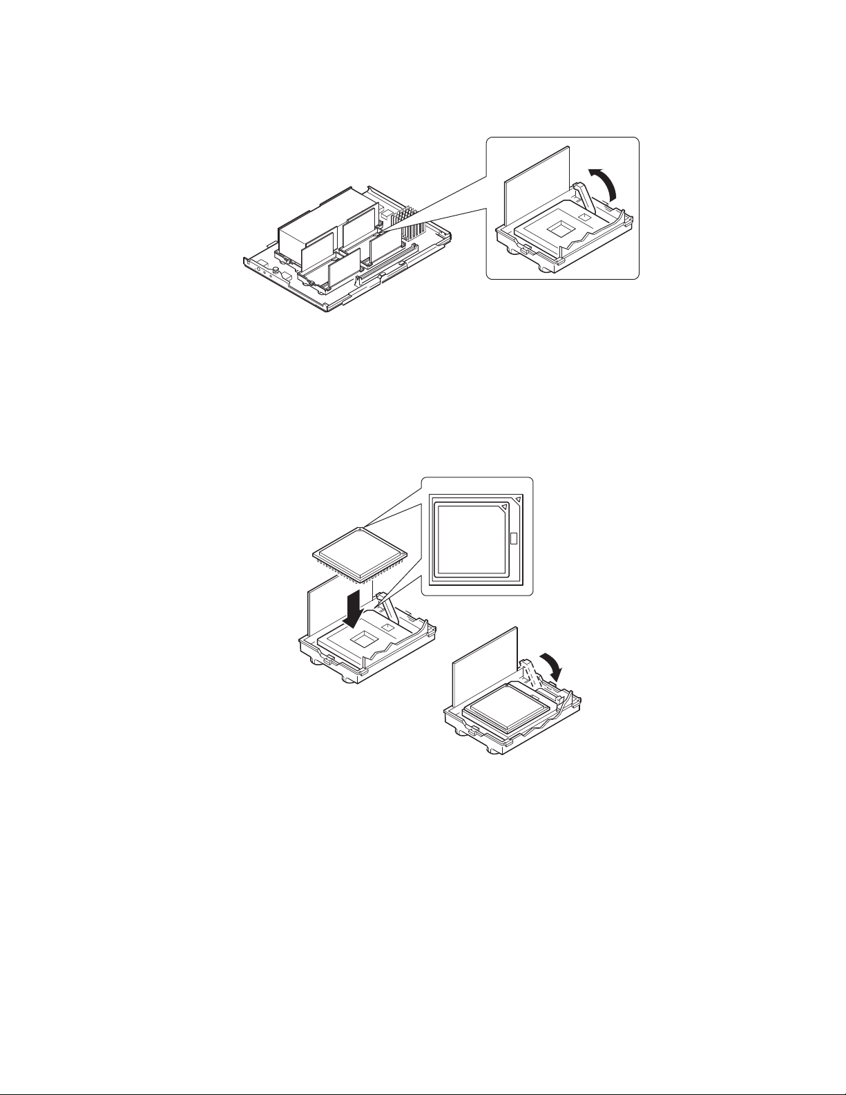
2. Raise the locking bar on the socket.
OM13267
Figure 15. Raising the Locking Bar
3. Orient the processor so that the triangle on the corner of the processor aligns with the triangle
on the corner of the socket (Figure 16).
4. Aligning the pins of the processor with the socket, insert the proc esso r into the soc ket. The
processor should drop into the socket without requiring any force.
5. Lower the locking bar completely.
OM13268
Figure 16. Installing Processors
Installing and Removing Components 79
Page 80

6. Following the instructions packaged with the applicat or, apply the rmal grea se to the proce sso r.
7. Insert the heat sink into the air baffle and place it on top of the processor (Figure 17, A).
8. Install both heat sink clips as follows:
a. Place the heat sink clip on the center tab of the retention module and slide the clip to the
right to engage the center tab.
b. Snap one end of the clip down over the corresponding tab on the retention module.
c. Snap the remaining end of the clip down over the corresponding tab.
A
D
B
A Heat sink C Retention module
B Socket and processor D Heat sink retention clips
Figure 17. Installing the Heat Sink
C
OM13269
80 Intel SPSH4 Server Platform Product Guide
Page 81

Removing Process ors
To remove processors:
1. Observe the safety and ESD precautions at the beginning of this document.
2. Remove both heat sink clips as follows:
a. Insert the heat sink clip extraction tool (see “Tools and Supplies Needed” on page 65) into
the slot at one end of the clip (Figure 18).
b. Press down on the tool until the clip clears the bottom edge of the tab on the retention
module and rotate the tool until the end of the clip is free of the tab.
c. Using the clip extraction tool, release the other end of the clip.
d. Slide the clip to the left to disengage it from the center tab on the retentio n modul e and
remove the clip.
3. Lift the heat sink straight out of the retention module.
4. Raise the locking bar on the socket.
5. Remove the processor from the socket.
OM13270
Figure 18. Removing a Processor
Installing and Removing Components 81
Page 82

Memory
This section includes instructions for removing and installing DIMMs on the memory board. For a
list of supported memory, call your service representative or visit the Intel Support website:
http://support.intel.com/support/motherboards/server/ssh4/spsh4/compat.htm
Installing DIMMs
CAUTION
Use extreme care when installing a DIMM. Applying too much pressure can
damage the socket. Keyed DIMMs insert only one way.
NOTE
✏
Load the DIMMs in the following order (Figure 19).
1. Bank 1: DIMMs #1, 2, 3, and 4
2. Bank 2: DIMMs #5, 6, 7, and 8
3. Bank 3: DIMMs #9, 10, 11, and 12
Always fill banks completely. Partially filled banks are ignored by the
system.
Use only approved DIMMs listed on the Intel customer support Web site:
http://support.intel.com/support/motherboards/server/ssh4/spsh4/compat.htm
To install DIMMs:
1. Remove the memory board (page 69), and place the board component-side up on a
nonconductive, static-free surfa ce.
2. Holding the DIMM only by its edges, remove it from its antistatic package.
82 Intel SPSH4 Server Platform Product Guide
Page 83

B
A
11
9
7
5
3
1
12
10
8
6
4
2
OM13272
Figure 19. Installing Memory
3. Open the plastic ejector levers at each end of the DIMM socket on the memory board
(Figure 19, A).
4. Orient the DIMM so that the notch in the bottom edge of the DIMM aligns with the keyed
socket on the memory board.
5. Insert the bottom edge of the DIMM into the socket and press down firmly on the DIMM until
it seats correctly. The plastic ejector levers should snap into place when the DIMM is seated.
6. Make sure that the plastic ejector levers on the socket ends are fully closed.
7. Reinstall the memory board (page 70).
Installing and Removing Components 83
Page 84

Removing DIMMs
1. Remove the memory board (page 69). Place the board component-side up on a nonconductive,
static-free surface.
2. Locate the DIMM you want to remove and gently push down on the plastic ejector levers
(Figure 20, A) to eject the DIMM from its socket.
3. Hold the DIMM only by its edges, being careful not to touch its components or gold edge
connectors. Carefully lift it away from the socket and store it in an antistatic package.
B
A
OM13271
Figure 20. Removing DIMMs
84 Intel SPSH4 Server Platform Product Guide
Page 85

Hot-Swap SCSI Drives
Hot-swap drives are installed in carriers that fit into the hot-swap drive bay. This section describes
the LED status indicators for the drive bays and gives instruc t ions for usi ng the dr ive car riers to
install and remove drives.
Checking a Hot-Swap SCSI Drive Status Indicator
Each hot-swap SCSI drive slot has an LED that indicates drive status (Figure 21). To view the
LEDs, open the front access door of the bezel.
B
A
A Front access door B LED status indicators
Figure 21. Hot-Swap SCSI Drive Bay and Status Indicators
Table 7 lists the LED states and the drive status indicated by each state.
Table 7. LED States for Hot-Swap SCSI Drive Status
LED State Status
Solid green The hard drive is present and powered on.
Flashing green The hard drive is active.
Solid yellow There is an asserted fault status on the hard drive.
Flashing yellow A rebuild of the hard drive is in progress.
Off The hard drive is not powered on.
OM13391
Installing and Removing Components 85
Page 86

Installing a Hot-Swap Drive in a Carrier
Before you can install a drive in the hot-swap drive bay, you must install the drive into a drive
carrier. To install a hot-swap drive in a carrier:
1. If the plastic air baffle is installed in the carrier, remove the four screws that attach the air baffle
to the carrier. Save the air baffle in case you later remove a drive.
A
B
C
D
OM13274
A Air Baffle C Carrier
B Screw D Plastic rail
Figure 22. Removing a Plastic Air Baffle from a Carrier
2. Remove the hard drive from its wrapper and place it on an antistatic surface.
3. Record the new drive model and serial number in your equipment log.
86 Intel SPSH4 Server Platform Product Guide
Page 87
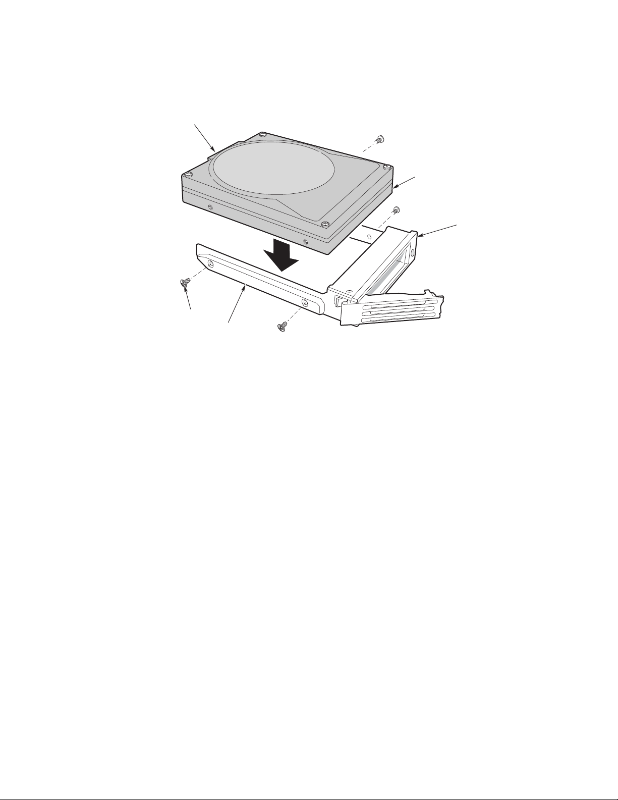
4. Place the drive in the carrier with the component side down.
5. Using the four screws removed earlier, attach the drive to the carrier.
A
B
E
D
C
OM13275
A SCA Connector D Plastic Rail
B Drive E Screw
C Carrier
Figure 23. Installing a SCSI Hard Disk Drive in a Carrier
Removing a Hot-swap Drive from a Carrier
To remove a hot-swap drive from a carrier:
1. Remove the carrier and drive from the drive bay.
2. Remove the four screws that secure the drive to the carrier.
3. Place the drive on an antistatic surface.
4. If you are going to reinstall the carrier without a drive, you must first replace the air baffle in
the carrier (Figure 22).
Installing and Removing Components 87
Page 88
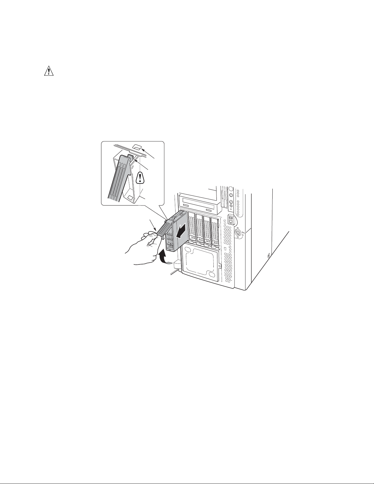
Removing and Installing Hot- Swap Disk Drives
CAUTION
Do not leave any drive slots without a drive or air baffle installed in the
carrier. An empty carrier installed in a drive slot reduces cooling efficiency
and can affect performance or cause damage due to overheating.
To replace a hot-swap disk drive:
1. Depress the green clip at the end of the plastic carrier handle. Pull the handle out to disengage
the carrier handle latch from the locking slot at the top of the drive bay (Figure 24, B and C).
C
B
A
OM13392
A Handle C Locking slot
B Latch
Figure 24. Removing a Drive Carrier
2. Carefully pull on the carrier handle and slide the carrier out of the bay.
3. Install a new drive into the carrier (page 86).
88 Intel SPSH4 Server Platform Product Guide
Page 89

4. Hold the carrier handle in the fully open position and slide the carrier into the desired bay.
5. Push the carrier into the drive bay until the carrier handle latch engages the locking slot in the
edge of the drive bay (Figure 25, C).
6. Push the handle closed until it clicks into position.
C
B
A
A Handle C Locking slot
B Latch
Figure 25. Installing a Drive Carrier
OM13393
Installing and Removing Components 89
Page 90

DC Power Supplies
The power supply bay accommodates up to three power supply modules. The bay contains a power
distribution board (PDB) that manages the delive ry of power from the power supply modules.
Checking the Power Status LEDs
Figure 26 shows the three power supply status LEDs.
A
B
C
OM10123
A Power LED C Fail LED
B Predictive Fail LED
Figure 26. Power and Standby LEDs
Table 8 lists the LED states and the power supply status indicated by each state.
Table 8. LED Power Supply Status Indicators
✏
Power
(Green)
Off Off Off No power to all power supplies.
Off Off On Power supply failure or no power to this power supply.
Blinking Off Off AC power present, standby outputs on.
On Off Off Power supply on, DC outputs normal.
On Off Blinking Current limit.
On On or Blinking Off Imminent failure predicted; fan performance problem.
NOTE
Predictive Fail
(Amber)
Fail
(Amber)
Status
If all power supply modules are functioning and all power cables from the
power distribution board are properly connected to the baseboard and other
components, but the server still won’t power on, replace the power
distribution board (page 117).
90 Intel SPSH4 Server Platform Product Guide
Page 91

Removing a Power Supply Module
To remove a power supply module:
1. Disconnect the AC power cord for the supply from the wall outlet or power source.
B
A
OM13394
A Screws B Latch handle
Figure 27. Removing a Power Supply Module
B
2. Remove the four screws that secure the power supply (Figure 27).
CAUTION
To avoid damaging the module, do not tilt or twist the power supply module
as you pull it from the power supply bay. The module disengaging from its
connector causes the initial resistance you will feel. Use even, steady force
to remove the supply.
3. Pull the latch handle to release the power supply module and carefully pull the module out of
the power supply bay.
4. Unplug the power cord from the power supply.
5. If you are not going to install a replacement module, you must install a filler panel in the vacant
slot.
Installing and Removing Components 91
Page 92

Installing a Power Supply Module
To install a power supply module:
1. If present, remove the filler panel from the vacant slot.
2. Holding the power supply latch handle in the open position, slide the power supply module into
the vacant slot until you feel resistance.
CAUTION
The module engaging its connector causes the resistance. To avoid
damaging the module, do not tilt or twist the power supply module as you
push it into the connector.
3. Guide the power cord through the strain relief notch in the latch handle and plug the cord into
the AC power connector on the back of the power supply module.
4. Press the latch handle down to engage the latches and secure the power supply to the chassis.
5. Insert and tighten the four screws that secure the power supply module to the chassis.
6. Connect the AC power cord to the wall outlet or other AC power source.
The green LED on the power supply module should be illuminated.
92 Intel SPSH4 Server Platform Product Guide
Page 93

PCI Add-In Boards
The SPSH4 server supports four hot-plug PCI add-in boards and four non-hot-plug PCI add-in
boards.
A
B
C
A Four hot-plug 64-Bit, 100-MHz
PCI-X add-in board slots
B Two non-hot-plug 64-Bit, 100-MHz
PCI-X add-in board slots
Figure 28. PCI Add-In Board Locations
C Two non-hot-plug 32-Bit, 33-MHz
PCI add-in board slots
OM13395
CAUTION
Be sure any empty expansion slots have a slot cover installed. An open
expansion slot reduces the cooling and EMI integrity of the server and can
affect performance and cause damage due to overheating.
Operating System Support for Hot-Plug Add-In Boards
Some operating systems support hot-plugging PCI add-in boards and some do not. Operating
system support is provided by a driver that you must install when setting up your server. Hot-plug
drivers are available on the System Resource CD in the Drivers directory. The driver files on the
CD include information on installing and using the hot-plug software.
If you don’t find a driver for your operating system on the System Resource CD, you can check the
Intel Customer Support website for the latest drivers:
http://support.intel.com/support/motherboards/server/ssh4/spsh4/
Without a driver, the operating system does not support hot-plug installation and removal of PCI
add-in boards. In that case, you must treat all eight PCI slots as non-hot-plug slots and follow the
instructions on pages 97 and 98 for installing and removing all PCI add-in boards.
Installing and Removing Components 93
Page 94

Checking the Status Indicators for a Hot-Plug Add-In Board
A bank of LED indicators on the back panel of the electronics bay indicates the status of the hotplug PCI add-in boards (Figure 29).
A
OM13396
A Status LED indicators
Figure 29. Status Indicators for Hot-Plug PCI Add-In Boards
Table 9 lists the LED states and the hot-plug PCI status indicated by each state.
Table 9. LED Hot-Plug PCI Status Indicators
Power LED State Status
Green Power to slot
Amber Fault on slot
Not lit No power to slot
94 Intel SPSH4 Server Platform Product Guide
Page 95

Installing a Hot-Plug PCI Add-In Board
To install a hot-plug PCI add-in board:
1. Remove the rear access cover (page 66).
2. If the LED for the slot indicates that power to the slot is on, turn it off by using the PCI hotplug application software on your system (see “Operating System Support for Hot-Plug Add-In
Boards” on page 93).
The LED adjacent to the slot should now be off.
3. Open the latches on the front and rear retention mechanisms (Figure 30, A and B).
4. If necessary, remove and save the expansion slot cover.
5. Prepare the new PCI board for installation:
a. Remove the add-in board from its protective wrapper. Be careful not to touch the
components or gold edge connectors. Place the add-in board with the component side up
on an antistatic surface.
b. Record the serial number of the add-in board in your equipment log.
c. Set jumpers or switches according to the manufacturer’s instructions.
A
B
OM13397
A Latch, rear retention mechanism
B Latch, front retention mechanism
Figure 30. Installing a Hot-Plug PCI Add-In Board
6. On the edge opposite the connectors, grasp the board by both corners. Orient the board to the
vacant hot-plug slot so that the metal retention bracket is toward the rear of the chassis.
7. Insert the board into the front and rear retention mechanisms. Carefully push down on the
board until it engages and fully seats in the slot connector.
Installing and Removing Components 95
Page 96

8. Close the front and rear latches.
9. Install the rear access cover.
10. Turn on power to the add-in board using the PCI hot-plug application software on your system.
Removing a Hot-Plug PCI Add-In Boar d
To remove a hot-plug PCI add-in board:
1. Remove the rear access cover (page 66).
2. If the LED for the slot indicates that power to the slot is on, turn it off by using the PCI hotplug application software on your system (see “Operating System Support for Hot-Plug Add-In
Boards” on page 93).
The LED adjacent to the slot should now be off.
3. Disconnect any cables attached to the board you are removing.
A
B
OM13398
A Latch, rear retention mechanism
B Latch, front retention mechanism
Figure 31. Removing a Hot-Plug PCI Add-In Board
4. Release the latches on the front and rear retention mechanisms (Figure 31, A and B).
5. Grasp the board at both corners, pull it out of the slot c onnec tor, and care fu lly sl id e it out of the
retention mechanisms. Store the board in an antistatic protective wrapper.
6. If you are not reinstalling a board in the same slot, install an expansion slot cover and install the
rear access cover. If you are installing a new board, follow the instructions on page 95.
96 Intel SPSH4 Server Platform Product Guide
Page 97

Installing a PCI Add-In Board in a Non-Hot-Plug Slot
CAUTION
The PCI add-in board slots located under the system board access cover are
not hot-plug slots.
To install a PCI add-in board in a non-hot-plug slot:
1. Disconnect the AC power cords from the power source or wall outlets.
2. Turn off all peripheral devices connected to the server system.
3. Remove the rear access cover (page 66) and the system board access cover (page 68).
4. If necessary, remove and save the expansion slot cover.
5. Prepare the new PCI board for installation:
a. Remove the add-in board from its protective wrapper. Be careful to not
touch the components or gold edge connectors. Place the board with the
component side up on an antistatic surface.
b. Record the serial number of the new add-in board in your equipment log.
c. Set jumpers or switches according to the manufacturer instructions.
6. Open the latches on the front and rear retention mechanisms (Figure 32, A and B).
7. On the edge opposite the connectors, grasp the board by both corners. Orient the board to the
vacant slot so that the metal retention bracket is toward the rear of the chassis.
A
B
OM13399
A Latch, rear retention mechanism
B Latch, front retention mechanism
Figure 32. Installing and Removing a Non-Hot-Plug PCI Add-In Board
Installing and Removing Components 97
Page 98

8. Insert the board into the front and rear retention mechanisms. Carefully push down on the
board until it engages and fully seats in the slot connector.
9. Close the front and rear latches.
10. Install the system board access cover and the rear access cover.
11. Turn on any peripheral devices connected to the system.
12. Connect the power cord and turn on power to the server.
Removing a PCI Add-In Board from a Non-Hot-Plug Slot
CAUTION
The PCI add-in board slots located under the system board access cover are
not hot-plug slots.
To remove a PCI add-in board from a non-hot-plug slot:
1. Disconnect the AC power cords from the power source or wall outlets.
2. Turn off all peripheral devices connected to the server system.
3. Remove the rear access cover (page 66) and the system board access cover (page 68).
4. Release the latches on the front and rear retention mechanisms.
5. Grasp the board by the top edge or corners, carefully pull it out of the connector, and slide it
free of the retention bracket.
6. If you are installing a new board, follow the instructions on page 97. If you are not installing
another PCI add-in board, continue with the next step below.
7. Install a slot cover over the vacant slot in the back panel.
8. Install the system board access cover and the rear access cover.
9. Turn on any peripheral devices connected to the system.
10. Connect the power cord and turn on power to the server.
98 Intel SPSH4 Server Platform Product Guide
Page 99

Cooling System Fans
The server accommodates four hot-swap fan modules.
CAUTION
Don’t remove a fan module while the server is powered on unless you have a
replacement unit available. Once you remove a fan module fro m the sys tem,
replace it within five minutes. Vacant spac es al ter ai rflow patte rns in the
server system and can cause overheating and damage to system components.
Checking a Fan Status Indicator
Fault LEDs for each fan module are located on the fan board (Figure 33). The LEDs are visible
through a cutout in the housing of each module. The red LEDs light to indicate a fan failure; during
normal operation, the LEDs remain unlit. A fan failure is also indicated by the general system fault
LED located on the front panel.
A
A Fan board B Fan status LEDs
Figure 33. Fan Status LEDs
B
OM13400
Installing and Removing Components 99
Page 100

Removing a Fan Module
To remove a fan module:
1. Remove the front access cover (page 67).
2. Grasp the fan module and pull it straight out of the foam baffle.
A Fan module
Figure 34. Removing and Installing a Fan Module
OM13401
Installing a Fan Module
✏ NOTE
If you are replacing a failed fan module, wait for the fan status LED to turn
off. Generally, this will take less than ten seconds.
To install a fan module:
1. Remove the front access cover (page 67).
2. Place the fan module into the empty slot of the fan assembly so that the fan connector mates
with the connector on the fan board.
3. Press down firmly to seat the fan module fully into the connector.
4. Check the fan status LED for the replacement fan. If the installation was successful, the
indicator will not be lit.
5. Install the front access cover.
100 Intel SPSH4 Server Platform Product Guide
 Loading...