

Page 1
Physical Installation Instructions for Intel®
Solid State Drive 750 Series
See the instructions below for how to install the Intel® Solid State Drive 750 Series hardware.
For compatibility with NVM Express* (NVMe*), use with a system based on an Intel® Z97
Chipset, Intel® X99 Chipset, or later chipset.
Before you begin
Caution
Disconnect the desktop board's power supply from its AC power source before you
connect or disconnect cables, or install or remove any board components.
Without first disconnecting the power supply, you risk personal injury or equipment
damage.
Some circuitry on the desktop board can operate even if the front panel power switch
is off.
Electrostatic discharge (ESD) can damage desktop board components. Install the board
at an ESD-controlled workstation. If an ESD-controlled workstation is unavailable,
wear an anti-static wrist strap or touch the surface of the anti-static package before
handling the board.
Prepare
Your board may have multiple PCIe* slots. The PCIe SSD needs a PCI Express* (PCIe) x4
connector. Best performance is with a PCIe 3.0 connector.
Page 2
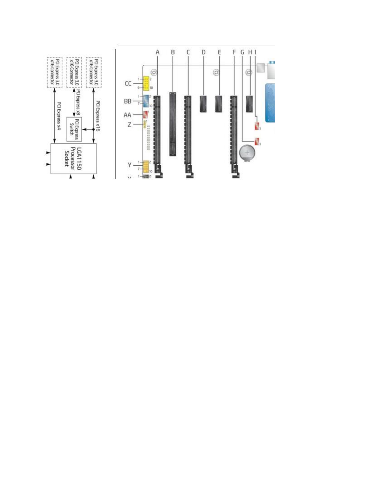
In our example:
Install the PCIe SSD in connector A, C, or F.
We recommend the connector closest to the processor/CPU (F) for best performance.
If you detect issues, the connector farthest from the CPU (A) might be more successful.
If you are using a third-party (add-in card) video card, place it in the PCIe connector
closest to CPU (F).
Installation steps for Intel® SSD 750 Series Add-in Card (AIC)
1. Find the proper PCIe 3.0 connector. Remove the screw and shield from your chassis.
2. Attach the SSD to the proper size I/O shield for your chassis. The half-height shield is in
the box packaging.
3. Insert the SSD.
4. Replace the chassis screw in the shield to hold the SSD in place.
See your chassis manual for more detailed instructions.
Page 3

Installation steps for the Intel® SSD 750 Series 2.5-inch drive
1. Mount the SSD in the chassis using screws to hold the SSD securely.
2. Connect the cable from the SSD (SFF 8639) to the motherboard connector (SFF 8643).
3. Connect SATA power to the connector on the cable.
See your chassis manual for more detailed instructions.
SFF 8639
SFF 8643
Page 4

Note
Make sure the electrical connection to the mini-SAS HD connector is PCIe, not SAS or
SATA. NVMe SSDs only support PCI Express* signals.
The SFF 8643 connector is also called a mini-SAS HD connector.
The SFF 8639 may also be called a SATA-express* drive connector with more signals.
 Loading...