

Page 1

Intel LB440GX 2U Rack Server Chassis
Technical Product Specification
Released version 1.0
August, 1999
245251-001
Page 2

Intel© LB440GX 2U Server Chassis TPS, Rev 1.0
Revision History
Revision Revision History Date
Rev 0.xx Initial release of the Intel LB440GX 2U Rack Server Chassis Technical Product
Specification (Part #245251-001)
Rev 0.9 Revisions 06/99
Rev 1.0 Legal and Trademark Review 8/12/99
03/99
INFORMATION IN THIS DOCUMENT IS PROVIDED "AS IS" WITH NO WARRANTIES WHATSOEVER,
INCLUDING ANY WARRANTY OF MERCHANTABILITY, NONINFRINGMENT OF INTELLECTUAL PROPERTY
RIGHTS OR ANY OTHER RIGHTS OF THIRD PARTIES OR OF INTEL, FITNESS FOR ANY PARTICULAR
PURPOSE, OR ANY WARRANTY OTHERWISE ARISING OUT OF ANY SPECIFICATION, SOFTWARE,
DOCUMENTATION OR OTHER MATERIALS REFERENCED HEREIN. Third parties may have intellectual
property rights which may be relevant to this document and the technologies discussed herein.
Nothing in this document constitutes a guarantee, warranty or license to any intellectual property right, express
or implied, by estoppel or otherwise. Intel makes no representations or warranties and specifically disclaims all
liability as to this document or the information contained herein with respect to sufficiency, reliability, accuracy,
completeness or usefulness of same. Furthermore, Intel makes no commitment to update the information
contained in this document, and Intel reserves the right to make changes at any time, without notice, to the
information contained in this document.
Except as provided in Intel's Terms and Conditions of sale for the products referenced herein, Intel assumes no
liability whatsoever, and Intel disclaims any express or implied warranty, relating to sale and/or use of Intel
products including liability or warranties relating to fitness for a particular purpose, merchantability, or
infringement of any patent, copyright or other intellectual property right. Intel products are not intended for use in
medical, life saving, or life sustaining applications. Intel may make changes to specifications and product
descriptions at any time, without notice. LIMITATION OF LIABILITY
. IN NO EVENT SHALL INTEL BE
LIABLE TO ANY PARTY FOR ANY DAMAGES WHATSOEVER (INCLUDING WITHOUT LIMITATION,
DIRECT, INDIRECT, SPECIAL, CONSEQUENTIAL, LOST PROFITS, BUSINESS INTERRUPTION,
COMPUTER FAILURE OR MALFUNCTION, OR LOST INFORMATION) SUFFERED AS A RESULT OF
USING OR RELIANCE UPON THE INFORMATION CONTAINED HEREIN.The Intel products referred to in this
document may contain design defects or errors known as errata which may cause the product to deviate from
published specifications. Current characterized errata are available on request.
Contact your local Intel sales office or your distributor to obtain the latest specifications and before placing your
product order.
Copyright © Intel Corporation 1999.
Pentium is a registered trademark of Intel Corporation. MMX is a trademark of Intel Corporation.
*Third-party marks and brands are the property of their respective owners.
ii
Page 3

Intel© LB440GX 2U Rack Server Chassis TPS Rev 1.0
Reference Documents
§ Intel L440GX+ Technical Product Specification (TPS) Rev 1.0
§ Power Supply, 300W, 5 Output, with PFC Rev 2.0
§ Entry-Level Electronics-Bay Specification Rev 0.90
§ ATX Specification Version 2.03
§ SCSI Accessed Fault-Tolerant Enclosures Interface Specification, Conner Peripherals and
Intel Corporation, Revision 1.00, October 17, 1995
§ SCSI Parallel Interface-2, draft proposal revision 20a
Page 4

Intel© LB440GX 2U Rack Server Chassis TPS Rev 1.0
TABLE OF CONTENTS
1 INTRODUCTION........................................................................................................................................1
2 CHASSIS ......................................................................................................................................................1
2.1 CHASSIS COLOR ...................................................................................................................................... 1
2.2 FRONT PANEL FEATURES.........................................................................................................................1
2.3 SECURITY................................................................................................................................................ 1
2.4 I/O PANEL ............................................................................................................................................... 1
2.5 CHASSIS VIEWS....................................................................................................................................... 2
2.6 CHASSIS DIMENSIONS..............................................................................................................................3
3 CHASSIS POWER SUBSYSTEM............................................................................................................... 4
3.1 MECHANICAL OUTLINE............................................................................................................................ 4
3.2 FAN REQUIREMENTS................................................................................................................................ 4
3.3 AC POWER LINE......................................................................................................................................4
3.4 POWER SUPPLY CONNECTOR PIN ASSIGNMENTS....................................................................................... 5
3.4.1 P1 Main Power Connector .............................................................................................................. 5
3.4.2 P10 ATX Aux Power Connector.......................................................................................................6
3.4.3 P2-P8, P11, P12 Peripheral Power Connector.................................................................................6
3.4.4 P9 Floppy Drive Power Connector.................................................................................................. 6
3.5 POWER SUPPLY/CHASSIS CONFIGURATION ...............................................................................................6
4 CHASSIS COOLING...................................................................................................................................7
5 CHASSIS PERIPHERAL BAYS..................................................................................................................8
5.1 3.5" FLOPPY DRIVE BAY.......................................................................................................................... 8
5.2 5.25" DRIVE BAY .................................................................................................................................... 8
5.3 LVD SCSI HOT-SWAP DRIVE BAYS ........................................................................................................ 8
6 FRONT PANEL............................................................................................................................................9
7 HOT-SWAP SCSI SUBSYSTEM............................................................................................................... 10
7.1 SUBSYSTEM PURPOSE ............................................................................................................................ 10
7.2 ABSTRACT............................................................................................................................................. 10
7.3 HOT-SWAP BACKPLANE BOARD LAYOUT............................................................................................... 11
7.3.1 Configuration Options................................................................................................................... 11
7.4 FUNCTIONAL DESCRIPTION.................................................................................................................... 12
7.4.1 68 pin LVD high density Hot-Swap Connectors .............................................................................. 12
7.4.2 SCSI Interface............................................................................................................................... 12
8 DUAL-SLOT PCI RISER .......................................................................................................................... 13
9 CHASSIS INTERCONNECTION.............................................................................................................13
9.1 CHASSIS INTERNAL CABLES...................................................................................................................13
9.2 CONNECTOR INTERFACES....................................................................................................................... 14
9.2.1 Hot-Swap Backplane and Peripheral Power Connectors................................................................ 14
10 SUPPORTED INTEL SERVER BOARDS............................................................................................15
10.1 INTEL
iv
L440GX+ DP SERVER BOARD................................................................................................... 15
Page 5

Intel© LB440GX 2U Rack Server Chassis TPS Rev 1.0
11 REGULATORY INFORMATION ........................................................................................................ 16
11.1 REGULATORY COMPLIANCE...................................................................................................................16
11.1.1 Safety Standards ............................................................................................................................ 16
11.1.2 EMC Regulations .......................................................................................................................... 17
11.1.3 Regulatory Compliance Markings..................................................................................................18
11.2 ELECTROMAGNETIC COMPATIBILITY NOTICE (USA)............................................................................... 18
11.2.1 FCC Declaration of Conformity..................................................................................................... 19
11.3 ELECTROMAGNETIC COMPATIBILITY NOTICES (INTERNATIONAL) ............................................................ 19
12 ENVIRONMENTAL LIMITS................................................................................................................ 20
12.1 SYSTEM OFFICE ENVIRONMENT ............................................................................................................. 20
12.2 SYSTEM ENVIRONMENTAL TESTING ....................................................................................................... 20
13 RELIABILITY, SERVICEABILITY, AND AVAILABILITY..............................................................21
13.1 MEAN-TIME-BETWEEN-FAILURE (MTBF)..............................................................................................21
13.2 SERVICEABILITY.................................................................................................................................... 21
Figures
FIGURE 1. ATX 2.03 I/O APERTURE..................................................................................................................... 1
FIGURE 2. FRONT AND REAR CHASSIS VIEWS........................................................................................................2
FIGURE 3. ISOMETRIC VIEW WITHOUT TOP COVER................................................................................................3
FIGURE 4. 80MM SYSTEM FAN.............................................................................................................................. 7
FIGURE 5. FRONT PANEL AND FUNCTIONS ............................................................................................................ 9
FIGURE 6. FUNCTIONAL DIAGRAM OF THE HOT-SWAP SCSI BACKPLANE ............................................................ 11
FIGURE 7. HOT SWAP SCSI BACKPLANE BLOCK DIAGRAM................................................................................. 12
FIGURE 8. ACTIVE PCI RISER BLOCK DIAGRAM.................................................................................................. 13
FIGURE 9. PERIPHERAL POWER CONNECTOR........................................................................................................14
Tables
TABLE 1. CHASSIS DIMENSIONS ..........................................................................................................................3
TABLE 2. POWER SUPPLY OUTPUT SUMMARY...................................................................................................... 4
TABLE 3. 20+4-PIN “MODIFIED ATX” POWER SUPPLY CONNECTOR.....................................................................5
TABLE 4. AUX ATX POWER CONNECTOR ............................................................................................................ 6
TABLE 5. PERIPHERAL POWER CONNECTOR ......................................................................................................... 6
TABLE 6. FLOPPY DRIVE POWER CONNECTOR ..................................................................................................... 6
TABLE 7. HSBP CONFIGURATION JUMPERS....................................................................................................... 11
TABLE 8. PIN TYPES ......................................................................................................................................... 14
TABLE 9. PERIPHERAL POWER CONNECTORS...................................................................................................... 14
TABLE 10. SYSTEM OFFICE ENVIRONMENT SUMMARY.........................................................................................20
v
Page 6
Intel© LB440GX 2U Rack Server Chassis TPS Rev 1.0
1 Introduction
This specification details the feature set of the Intel® LB440GX 2U rack server chassis, an ATX-form
factor server chassis designed for the Intel® L440GX+ server board.
Intel LB440GX features include:
• 2U rack mount chassis (3.46” H x 16.75” W x 28” L)
• One floppy drive
• Two 32-bit/33 MHz PCI slots on the included PCI Riser Card
• Four hot-swap hard drive bays capable of supporting two 1” and two 1.6” LVD SCSI hard drives
• Two system fans
• One 300-Watt PFC PS/2* power supply
2 Chassis
The chassis is 3.46 inches high, 16.75 inches wide, and 28 inches long. The rear I/O panel conforms
to the ATX Specification version 2.03, supporting two expansion cards.
2.1 Chassis Color
The primary exterior chassis color will match Intel Color Standard 513505 (dusty beige).
2.2 Front Panel Features
The front panel is pressed SECC with four removable SCSI drive bays, two 1.6” and two 1”. The front
panel also allows for a floppy drive and full-size CD-ROM. The front panel contains a power button
power indicator LED, and hard drive activity LED’s.
2.3 Security
At the chassis level, no security option is provided (no chassis intrusion).
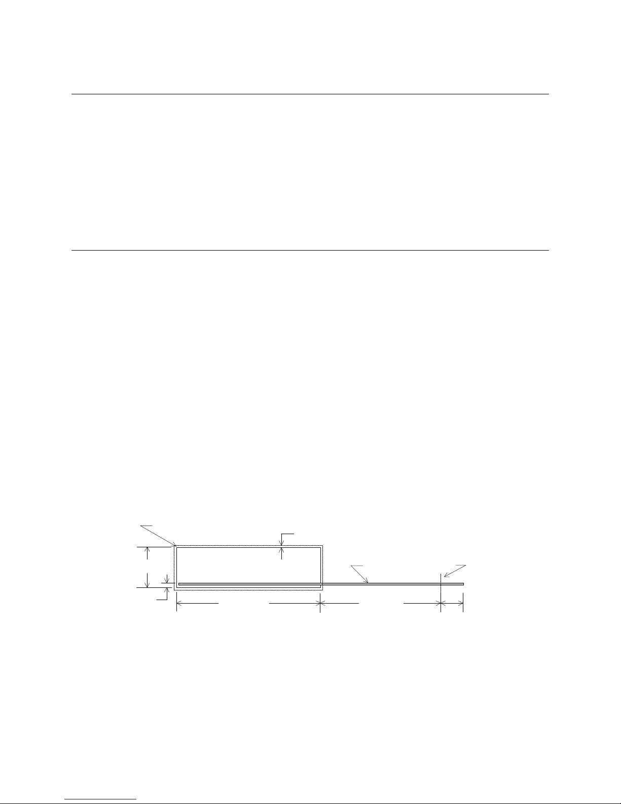
2.4 I/O panel
All input/output connectors are accessible on the rear of the chassis and an ATX 2.03-compatible
cutout is provided for I/O shield installation. A metal I/O shield with appropriate Electromagnetic
Interference (EMI) gasket is installed in the cutout in order to maintain EMI-compliance levels. The
I/O cutout dimensions (measured in inches) are shown in Figure 1 below.
R 0.039 MAX, TYP
1.750 ± 0.008
(0.150)
1
0.100 Min keepout around opening
I/O Aperture
Figure 1. ATX 2.03 I/O Aperture
Baseboard
5.196 ± 0.0106.250 ± 0.008
Datum 0,0
(0.650)
Page 7
Intel© LB440GX 2U Rack Server Chassis TPS Rev 1.0
Bays
Bays
Drive LEDs
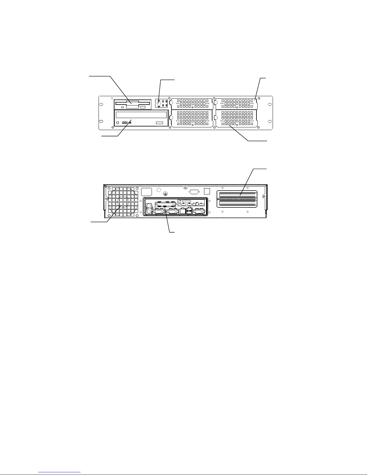
2.5 Chassis Views
Floppy Drive
CD-ROM Drive Bay
Exhaust Grill
Power Switch and
I/O Panel: Keyboard, Mouse, Parallel
Port, 2 Serial Ports, LAN, 2 USB Ports,
and Video
Two 1” Hot-swap Drive
Two 1.6” Hot-swap Drive
Two PCI Bays
Figure 2. Front and Rear Chassis Views
2
Page 8
Intel© LB440GX 2U Rack Server Chassis TPS Rev 1.0
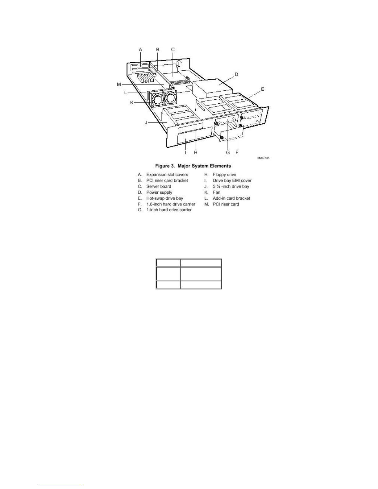
Figure 3. Isometric View without Top Cover
2.6 Chassis Dimensions
Height 2U (80 mm)
Width 16.75” (480
mm)
Depth 28” (711 mm)
Table 1. Chassis Dimensions
3
Page 9

Intel© LB440GX 2U Rack Server Chassis TPS Rev 1.0
3 Chassis Power Subsystem
This chassis uses a single standard PS/2 form factor power supply. Variations may be chosen for
future board sets to satisfy the chassis power, power distribution, thermal performance, acoustic
noise and cost requirements.
The form factor was chosen to optimize the overall chassis dimensions. The typical PS/2 form factor
power supply with a remote enable feature can be used. The remote enable feature permits the
chassis power to be activated from a variety of sources, allowing the implementation of “Wake On
LAN*” (WOL) or other remote management features. The 300-watt PFC (Power Factor Correction)
power supply features a 24-pin main power connector and a 6-pin Auxiliary ATX power connector.
The following table is a brief overview:
ATX 300W Non-PFC 719680-
002
+5 VDC Output 26 Amp Max
+12 VDC Output 10 Amp Max
-12 VDC Output 0.5 Amp Max
-5 VDC Output 0.25 Amp Max
+3.3 VDC Output 16 Amp Max
+5 VDC Standby 800mA Max
Output balancing Total combined output power of +3.3V
AC Line Voltage Autorange
AC Line Frequency 50/60 Hz
AC Input Current 4.6 Amp at 115 VAC 2.3 Amp at 220 VAC
P/S Rating, Maximum Continuous
Current
and +5V shall not exceed 167 W.
Table 2. Power Supply Output Summary
3.1 Mechanical Outline
The mechanical outline and dimensions of the power supply adhere to the standard PS/2 Form factor.
The approximate dimensions are: 140mm high x 86mm wide x 150mm deep.
3.2 Fan Requirements
The power supply incorporates an 80mm low-acoustic-noise fan to exhaust air. The sound pressure
level is measured at a distance of 0.1 meter from each side of the power supply in a free field. The
worst-case peak value of the measurements shall not exceed 38 dBA at 23°C ± 2°C.
Due to the increased output requirements of the 5V standby circuit, power supply thermal margins
are difficult to maintain while the system is in the “off” state. For this reason, the power supply fan
will run at a reduced RPM when the system is off.
3.3 AC Power Line
The power supply is specified to operate from 100-120VAC, 200-240VAC, at 50 or 60Hz and is autoranging. The power supply is tested to meet these voltages, and has been tested (but not specified)
in a configured system at ± 10% of the voltage ranges, and similarly ± 3Hz on the line input
frequency.
The power supply, in a configured system, is specified to operate without error at full power supply
4
Page 10

Intel© LB440GX 2U Rack Server Chassis TPS Rev 1.0
output load, nominal input voltage, with line source interruptions not to exceed one period of the AC
input power frequency (i.e. 20 milliseconds at 50Hz).
The power supply is not damaged by AC surge ring wave up to 3.0kV/500A. This ring wave is a
100kHz damped oscillatory wave with a specified rise-time for the linear portion of the initial halfcycle of 0.5µsec. Additionally, the chassis will not be damaged by a unidirectional surge waveform of
up to 1.5kV/3000A, with a 1.2µsec rise time and 50µsec duration. Further details on these
waveforms can be obtained in ANSI/IEEE STD C62.45-1992.
3.4 Power Supply Connector Pin Assignments
3.4.1 P1 Main Power Connector
Housing: 24-pin Molex* 39-01-2240, Contact: Molex 39-00-0038
Pin Signal 18 AWG
1 +3.3VDC Orange 13 +3.3VDC Orange
2** +3.3VDC
+3.3V remote sense
3** COM
3.3V remote sense RTN
4 +5VDC Red 16 PS_ON_L Green
5 COM Black 17 COM Black
6 +5VDC Red 18 COM Black
7 COM Black 19 COM Black
8 PWR OK Gray 20 -5V White
9 5VSB Purple 21 +5VDC Red
10 +12VDC Yellow 22 +5VDC Red
11 +12VDC Yellow 23 +5VDC Red
12 +3.3VDC Orange 24 COM Black
Color
Orange
Orange
Black
Black
Pin Signal 18 AWG
Color
14 -12VDC Blue
15 COM Black
Table 3. 20+4-pin “Modified ATX” Power Supply Connector
§ Note**: The 3.3V power and 3.3V remote sense are double crimped into a single contact at
pin 2. The 3.3V remote sense return and COM are double crimped into a single contact at
pin 3.
§ The “Modified ATX” main power connector is configured as the standard ATX 20 (2x10) pin
connector plus a 2x2 (4) pinout designed to supply additional +5VDC to the board. For
connecting this into the Intel L440GX+ server board, use the 24-pin power connector on the
board.
5
Page 11

Intel© LB440GX 2U Rack Server Chassis TPS Rev 1.0
3.4.2 P10 ATX Aux Power Connector
Housing: 6-pin Molex 90331-0010, Contact: Molex 09-50-0277
Pin Signal 18 AWG
Color
1 COM Black 4 +3.3VDC Orange
2 COM Black 5 +3.3VDC Orange
3 COM Black 6 +5VDC Red
Pin Signal 18 AWG
Table 4. Aux ATX Power Connector
3.4.3 P2-P8, P11, P12 Peripheral Power Connector
Housing: Amp 1-480424-0, Contact: Amp 61314-1
Pin Signal 18 AWG
1 +12VDC Yellow
2 COM Black
3 COM Black
4 +5VDC Red
Color
Color
Table 5. Peripheral Power Connector
3.4.4 P9 Floppy Drive Power Connector
Housing: Amp 171822-4
Pin Signal 18 AWG
1 +5VDC Red
2 COM Black
3 COM Black
4 +12VDC Yellow
Color
Table 6. Floppy Drive Power Connector
3.5 Power Supply/Chassis Configuration
The Intel LB440GX 2U rack server platform can only be configured with a single power supply. For
a more detailed specification on the power supply, see document 719680, the specification for the
300-Watt power supply with PFC.
6
Page 12

Intel© LB440GX 2U Rack Server Chassis TPS Rev 1.0
AIR FLOW
80 ±.5
GROUND BLACK
All measurements are in millimeters
4 Chassis Cooling
Two system fans and the power supply fan provide cooling for the processor(s), hard drives, and
add-in cards. Two 80mm system fans are mounted in the middle of the chassis. All chassis fans
provide a single tachometer output for RPM detection that the server board can make available for
server management monitoring and alert functions. Removal of the top cover gives access to the
fans, which then can be easily changed with the system powered down.
3 2 1
230 ±30
ROTATION
71.5 ±.3
SIGNAL AND WIRE COLOR
+12V RED
TACHOMETER
4.-
Φ4.5 DIA
4.0X 2
±.5
25.
CONNECTOR PIN OUT
1
2
3
LABEL SIDE
7
Figure 4. 80mm System Fan
Page 13

Intel© LB440GX 2U Rack Server Chassis TPS Rev 1.0
5 Chassis Peripheral Bays
5.1 3.5" Floppy Drive Bay
The chassis provides for the installation of a 3.5“ floppy drive above the 5.25” CD-ROM drive bay.
Removal of the top cover provides access for replacement of the floppy drive.
5.2 5.25" Drive Bay
The chassis supports one half-height (1.6” high) removable media peripheral devices (typically CDROM). As a guideline based on cooling capabilities, the maximum recommended power per device is
17W. Thermal performance of specific devices must be verified to ensure compliance to the drive
manufacturer’s specifications.
The 5.25" peripherals are removable from the front of the chassis after removal of the top cover.
5.3 LVD SCSI Hot-Swap Drive Bays
The LB440GX 2U rack server chassis supports up to four (two 1” high and two 1.6” high) 3.5" LVD
Ultra-2 SCSI hard drives which are accessible from the front of the chassis. Four low-cost SECC
carriers are provided with the chassis to be installed on the hard drives.
Thermal performance of specific hard drives must be verified to ensure compliance to the drive
manufacturer’s specifications. Peripherals must be specified to operate at a maximum ambient
temperature of 50°C.
8
Page 14

Intel© LB440GX 2U Rack Server Chassis TPS Rev 1.0
6 Front Panel
The front panel board includes the Power On/Off button, a green Power On LED, four green hard
drive activity LED’s (not drive failures), which are visible through the front inlay.
A four-pin connector is provided on the front panel board for connection to the hot-swap backplane
for drive activity of drives number 1 and 2.
A four-pin connector is provided on the front panel board for connection to the hot-swap backplane
for drive activity of drives number 3 and 4.
A four-pin connector is provided on the front panel board for connection to the baseboard for power
LED.
A two-pin connector is provided on the front panel board for connection to the baseboard for the
power switch.
Power Switch
Power LED
Hard Drive Activity LEDs
Figure 5. Front Panel and Functions
9
Page 15

Intel© LB440GX 2U Rack Server Chassis TPS Rev 1.0
7 Hot-Swap SCSI Subsystem
The Intel LB440GX 2U rack server chassis has two independent, identical hot-swap backplanes.
Each backplane supports two Ultra2 SCSI hot-swappable drives. Two configurable switches on the
back of each backplane (see Figure 11) determine the identification of each drive. The backplanes
are then daisy chained with a standard 68-pin Ultra-2 SCSI cable. The hot-swap SCSI subsystem
supports the following features:
§ Hot-swapping of Ultra-2 SCSI drives, that allows connection of SCSI devices while the power
is on.
§ Full dual mode LVD operation, compliant with Fast, Ultra and Ultra-2 SCSI bus operation.
7.1 Subsystem Purpose
The Intel LB440GX 2U rack server chassis hot-swap SCSI backplane performs the tasks associated
with hot-swappable SCSI drives. The backplane design allows for:
§ Four high density 68 pin connectors for four LVD Ultra-2 compatible SCSI drives
§ Active termination on SCSI bus
§ Per-drive power control, including automatic slot power down upon drive removal
7.2 Abstract
The Intel LB440GX hot-swap SCSI backplane is made up of the following functional blocks:
§ SCSI Bus with Ultra-2 high density LVD 68 pin drive connectors, and active terminators
§ SCSI drive power control
§ Configuration jumpers
10
Page 16

Intel© LB440GX 2U Rack Server Chassis TPS Rev 1.0
7.3 Hot-Swap Backplane Board Layout
The backplanes reside in the hot-swap drive bay of the Intel LB440GX 2U rack server chassis. Note
this is a passive backplane, which means there is no firmware associated with it (no SAF-TE ASIC).
As a result, server management will not be able to determine the status of each drive.
The following diagram shows the layout of components and connectors on the hot-swap SCSI
backplane printed circuit board.
DISK POWER
CONNECTOR
TERMINATOR
ENABLE : SHORT
DIABLE : OPEN
68Pin SCSI CON
NECTOR
SE/LVD SCSI
TERMINATOR
Figure 6. Functional Diagram of the Hot-Swap SCSI Backplane
SCSI ID SW
SW2 SW1 DISK1 DISK0
OFF OFF 1 0
OFF ON 3 2
ON OFF 5 4
ON ON 9 8
7.3.1 Configuration Options
The following table lists all possible SCSI ID switch configurations of the Intel LB440GX hot-swap
SCSI backplane and the resulting SCSI ID for the position of each switch.
11
SW 2 SW 1 ID of Disk 1 ID of Disk
0
OFF OFF 1 0
OFF ON 3 2
ON OFF 5 4
ON ON 9 8
Table 7. HSBP Configuration Jumpers
Page 17

Intel© LB440GX 2U Rack Server Chassis TPS Rev 1.0
7.4 Functional Description
This section defines the architecture of the Intel LB440GX Hot-swap SCSI Backplane, including
descriptions of functional blocks and how they operate. The following figure shows the functional
blocks of the Hot-swap SCSI Backplane. An overview of each block follows.
68P SCSI
Connector
ID SELECT SW
DIP2 DIP1 SLOT0 SLOT1
OFF OFF 1 0
OFF ON 3 2
ON OFF 5 4
ON ON 9 8
EPLD
Drive Power
Control
ID Config
Presence
Presence
SCA-2 Connector 0
(Upper Slot)
SCA-2 Connector 1
LVD/SE Multimode
TERMINATOR
Terminator
Enable Jumper(JP2)
Short : Enable
Open : Disable
(Lower Slot)
Figure 7. Hot Swap SCSI Backplane Block Diagram
7.4.1 68 pin LVD high density Hot-Swap Connectors
The Intel LB440GX contains two hot swap backplane boards with two high-density LVD connectors
on each backplane. The connectors provide power and SCSI signals using a single connector. Each
SCSI drive attaches to the backplane using one of these connectors.
7.4.2 SCSI Interface
The SCSI interface on the Intel LB440GX Hot-swap SCSI Backplane provides the required circuitry
between the SCSI bus and the Adaptec controller, which contains the intelligence for the backplane.
The interface consists of an Altera EPLD. After powering on, the Altera EPLD detects the presence of
disks in the slots and powers them on. The SCSI ID configuration of the disks is configured on the
backplanes by using two DIP-switches located on the boards. See section 7.3.1 for the SCSI ID
configuration options.
12
Page 18

Intel© LB440GX 2U Rack Server Chassis TPS Rev 1.0
8 Dual-Slot PCI Riser
The Intel LB440GX employs a dual-slot PCI riser, which provides two full-length 32-bit/33Mhz PCI.
The riser is an active riser due to the extra PCI Bus Bridge on the card. The riser resides in PCI slot
number 5 of the Intel L440GX+ server board.
P_INT_B <- INT_A
P_INT_C <- INT_B
P_INT_D <- INT_C
P_INT_A <- INT_D
Slot 1 (Upper Slot)
IDSEL 21
PCI Slot5
Primary PCI
IDSEL 20
TI PCI
Bridge
PCI2031
32Bits/33MHz
Secondary PCI
IDSEL 20
Slot 0 (Lower Slot)
P_INT_A <- INT_A
P_INT_B <- INT_B
P_INT_C <- INT_C
P_INT_D <- INT_D
Figure 8. Active PCI Riser Block Diagram
Note: The Intel L440GX+ baseboard provided in the Intel LB440GX system contains 6 PCI slots
and 1 ISA slot. PCI Slot 5 contains the PCI Riser Card. The other slots are inactive and should not be
used. Any (up to two) PCI cards in the system should be inserted in the slots on the PCI Riser card.
9 Chassis Interconnection
9.1 Chassis Internal Cables
Front panel board to hot-swap backplanes
§ A four-pin connector connect the front panel board to the second hot-swap backplane to
transfer drive activities to the LED indicators of drives 3 and 4.
§ A four-pin connector connects the front panel board to the first hot-swap backplane to
transfer drive activities to the LED indicators of drives 1 and 2.
Front panel board to server board
§ A two-pin connector cable provides Power On/Off function.
§ A four-pin connector cable connects the server board to the front panel board to provide
server board power status.
13
Page 19

Intel© LB440GX 2U Rack Server Chassis TPS Rev 1.0
Server board to hot-swap backplanes
§ An Ultra-2 SCSI cable (68-pin) is provided to interface from the installed server board to
the two hot-swap backplanes.
§ Two high-density 68-pin connectors in each backplane provide interface between the hotswap SCSI backplane and hot-swap SCSI devices.
9.2 Connector Interfaces
Each pin is classified by type, as shown in the following table.
Type Description
PWR Power connection (power or
I/O Bi-directional signal
O Output signal
I Input signal
O/C Open-collector output signal
O/D Open-drain output signal
ground)
Table 8. Pin Types
9.2.1 Hot-Swap Backplane and Peripheral Power Connectors
The hot-swap backplane power connector and peripheral power connectors are a standard fourpin shrouded plastic PC power connectors with mechanical keying. Connector pinout is shown
below.
Figure 9. Peripheral power connector
Name Pin Description
+12V 1 +12 Volt power supply (yellow
GND 2 0V Electrical ground (black wire)
GND 3 0V Electrical ground (black wire)
+5V 4 +5 Volt power supply (red wire)
wire)
Table 9. Peripheral power connectors
14
Page 20

Intel© LB440GX 2U Rack Server Chassis TPS Rev 1.0
10 Supported Intel Server Boards
The following is a summary of the feature sets for Intel server boards supported by the Intel
LB440GX 2U rack server chassis. Please refer to the appropriate server board Technical Product
Specification for greater detail.
10.1 Intel L440GX+ DP Server Board
§ Support for Single or Dual Pentium® II processors of identical speed and stepping, current
revision
§ Designed around the Intel® 440GX AGPSet, PIIX4e, I/O APIC devices for full MPS 1.4 compliance.
§ 100MHz System Bus (Front Side Bus)
§ Support for up to 2 GB 100MHz “PC/100” compliant registered or 1GB of unbuffered ECC or Non-
ECC SDRAM DIMMs (4 sites)
§ Dual Peer PCI buses providing 6 PCI slots.
§ Adaptec* AIC-7896 Dual function PCI SCSI controller providing Ultra2 (LVDS) wide and Ultra
wide SCSI channels. Support for Adaptec ARO-1130U2 RAIDPort* “zero channel” RAID
controller.
§ Intel® 82559 PCI 10/100Mbit Ethernet controller with integrated physical layer. Onboard RJ-45
Network connector.
§ Cirrus Logic* GD5480 PCI SVGA graphics controller, 2MB of Synchronous Graphics memory
(SGRAM)
§ PCI IDE controller (in PIIX4E) providing dual independent Ultra DMA/33 IDE interfaces, each able
to support 2 IDE drives.
§ Compatibility I/O device integrating floppy, dual serial and parallel ports, all connectors provided.
§ Universal Serial Bus (USB) support with two USB connectors.
§ Integration of server management features, including thermal, voltage, fan, and chassis
monitoring into one controller. Emergency Management Port (EMP) feature. Introducing Platform
Event Paging (PEP) Feature enabling remote notification of significant server management
events.
§ Flash BIOS support for all of the above.
15
Page 21

Intel© LB440GX 2U Rack Server Chassis TPS Rev 1.0
11 Regulatory Information
11.1 Regulatory Compliance
11.1.1 Safety Standards
UL 1950 - CSA 950-95, 3rd Edition, July 28, 1995
The Standard for Safety of Information Technology Equipment including Electrical Business
Equipment. (USA and Canada). This product has been evaluated and complies with UL1950 – CSA
950-95 3rd Edition. However, if a UL1950 2nd Edition modem telecommunications add-in card is used,
the system will be deemed to comply with UL 1950 2nd Edition/CSA950-93.
EN 60 950, 2nd Edition, 1992
The Standard for Safety of Information Technology Equipment including Electrical Business
Equipment. (European Union)
IEC 950, 2nd edition, 1991
The Standard for Safety of Information Technology Equipment including Electrical Business
Equipment. (International)
EMKO-TSE (74-SEC) 207/94
Summary of Nordic deviations to EN 60 950. (Norway, Sweden, Denmark, and Finland)
16
Page 22

Intel© LB440GX 2U Rack Server Chassis TPS Rev 1.0
11.1.2 EMC Regulations
FCC Class B
Title 47 of the Code of Federal Regulations, Parts 2 and 15, Subpart B, pertaining to unintentional
radiators. (USA)
CISPR 22, 2nd Edition, 1993, Amendment 1, 1995
Limits and methods of measurement of Radio Interference Characteristics of Information Technology
Equipment. (International)
EN 55 022, 1995
Limits and methods of measurement of Radio Interference Characteristics of Information Technology
Equipment. (Europe)
EN 50 082-1, 1992
Generic Immunity Standard. Currently, compliance is determined via testing to IEC 801-2, -3 and -4.
(Europe)
VCCI Class B (ITE)
Implementation Regulations for Voluntary Control of Radio Interference by Data Processing
Equipment and Electronic Office Machines. (Japan)
ICES-003, Issue 2
Interference Causing Equipment Standard, Digital Apparatus. (Canada)
Australian Communication Authority (ACA)
Australian C-tick mark, limits and methods of measurement radio interference characteristics of
information technology equipment to ASNZS 3548 (Australian requirements based on CISPR 22
requirements).
New Zealand Ministry of Commerce
Australian C-tick mark, limits and methods of measurement radio interference characteristics of
information technology equipment to ASNZS 3548 (New Zealand requirements based on CISPR 22
requirements). New Zealand authorities accept ACA C-Tick Compliance Mark.
17
Page 23

Intel© LB440GX 2U Rack Server Chassis TPS Rev 1.0
11.1.3 Regulatory Compliance Markings
This product is provided with the following Product Certification Markings.
• UL, cUL Listing Marks
• CE Mark and CE Declaration of Conformity
• The CE marking on this product indicates that it is in compliance with the European
community’s EMC (89/336/EEC) and low voltage directives (73/23/EEC)
• NEMKO Mark
• German GS Mark
• FCC, Class B Markings (Declaration of Conformity)
• ICES-003 (Canada Compliance Marking)
• C-Tick Mark (Australia Compliance Marking)
11.2 Electromagnetic Compatibility Notice (USA)
This equipment has been tested and found to comply with the limits for a Class B digital device,
pursuant to Part 15 of the FCC Rules. These limits are designed to provide reasonable protection
against harmful interference in a residential installation. This equipment generates, uses, and can
radiate radio frequency energy and, if not installed and used in accordance with the instructions, may
cause harmful interference to radio communications. However, there is no guarantee that
interference will not occur in a particular installation. If this equipment does cause harmful
interference to radio or television reception, which can be determined by turning the equipment off
and on; the user is encouraged to try to correct the interference by one or more of the following
measures:
• Reorient or relocate the receiving antenna.
• Increase the separation between the equipment and the receiver.
• Connect the equipment into an outlet on a circuit different from that to which the
receiver is connected.
• Consult the dealer or an experienced radio/TV technician for help.
Any changes or modifications not expressly approved by the grantee of this device could void the
user’s authority to operate the equipment. The customer is responsible for ensuring compliance of
the modified product.
Only peripherals (computer input/output devices, terminals, printers, etc.) that comply with FCC Class
B limits may be attached to this computer product. Operation with noncompliant peripherals is likely
to result in interference to radio and TV reception.
All cables used to connect to peripherals must be shielded and grounded. Operation with cables,
connected to peripherals that are not shielded and grounded may result in interference to radio and
TV reception.
✏
NOTE
If a Class A device is installed within this system, then the system is
to be considered a Class A system. In this configuration, operation of
this equipment in a residential area is likely to cause harmful
interference.
18
Page 24

Intel© LB440GX 2U Rack Server Chassis TPS Rev 1.0
11.2.1 FCC Declaration of Conformity
Product Type: BAR2
This device complies with Part 15 of the FCC Rules. Operation is subject to the following two
conditions: 1) This device may not cause harmful interference, and 2) this device must accept any
interference received, including interference that may cause undesired operation.
Intel Corporation
5200 N.E. Elam Young Parkway
Hillsboro, OR 97124-6497
Phone: 1-800-628-8686
Cet appareil numérique respecte les limites bruits radioélectriques applicables aux appareils
numériques de Classe B prescrites dans la norme sur le matériel brouilleur: “Appareils
Numériques”, NMB-003 édictée par le Ministre Canadian des Communications.
(English translation of the notice above) This digital apparatus does not exceed the Class B limits for
radio noise emissions from digital apparatus set out in the interference causing equipment standard
entitled “Digital Apparatus,” ICES-003 of the Canadian Department of Communications.
11.3 Electromagnetic Compatibility Notices (International)
(English translation of the notice above) This is a Class B product based on the standard of the
Voluntary Control Council For Interference (VCCI) from Information Technology Equipment. If this is
used near a radio or television receiver in a domestic environment, it may cause radio interference.
Install and use the equipment according to the instruction manual.
When used near a radio or TV receiver, it may become the cause of radio interference.
Read the instructions for correct handling.
This equipment has been tested for radio frequency emissions and has been verified to meet
CISPR 22 Class B.
19
Page 25

Intel© LB440GX 2U Rack Server Chassis TPS Rev 1.0
12 Environmental Limits
12.1 System Office Environment
Parameter Limits
Operating Temperature +5oC to +35oC with the maximum rate of change not to
exceed 10oC per hour.
Non-Operating
Temperature
Non-Operating Humidity 95%, non-condensing @ 30oC
Acoustic noise < 45 dBA in an idle state at typical office ambient
Operating Shock No errors with a half sine wave shock of 2G (with 11
Package Shock Operational after a 24 inch free fall, although cosmetic
ESD 20kV per Intel Environmental test specification
-40oC to +70oC
temperature (65-75F)
millisecond duration).
damage may be present
Table 10. System Office Environment Summary
12.2 System Environmental Testing
The system will be tested per the Environmental Standards Handbook, Intel Doc.#662394-03. These
tests shall include:
Temperature Operating and Non-Operating
Humidity Non-Operating
Packaged and Unpackaged Shock
Packaged and Unpackaged Vibration
AC Voltage, Freq. & Source Interrupt
AC Surge
Acoustics
ESD
EMC Radiated Investigation
20
Page 26

Intel© LB440GX 2U Rack Server Chassis TPS Rev 1.0
1 minute
13 Reliability, Serviceability, and Availability
13.1 Mean-Time-Between-Failure (MTBF)
MTBF data was being collected at the time of the generation of this specification. It will be provided
in a future revision of this specification or a Specification Update.
13.2 Serviceability
The system is designed to be serviced by qualified technical personnel only.
The desired Mean Time To Repair (MTTR) of the system is 30 minutes including diagnosis of the
system problem. To meet this goal, the system enclosure and hardware have been designed to
minimize the MTTR.
Following are the maximum times that a trained field service technician should take to perform the
listed system maintenance procedures, after diagnosis of the system.
Remove cover
Remove and replace hard disk drive 1 minute
Remove and replace 5 ¼ peripheral device 5 minutes
Remove and replace power supply 5 minutes
Remove and replace rear drive bay fans 3 minutes
Remove and replace front system fan 5 minutes
Remove and replace expansion board 5 minutes
Remove and replace front panel board 5 minutes
Remove and replace baseboard (with no expansion boards) 10 minutes
Overall MTTR 20 minutes
21
 Loading...