

Page 1

Intel in
Communications
Building Fault-tolerant SS7
Systems Using the
Intel
®
NetStructure™
SIU520 SS7 Signaling Gateway
Application Note
Page 2

Building Fault-tolerant SS7 Systems Using the Intel®NetStructure™ SIU520 SS7 Signaling Gateway Application Note
Table of Contents
Abstract 1
Introduction 1
Overview of SIU Operation 2
Circuit-switched API Operation 2
Transaction-based API Operation 3
Management Interface 3
Potential Points of Failure 3
Failure of SS7 Links 4
Failure of Routes 5
Failure of Power Supply 6
Failure of Signaling Interface Unit 6
Routing Architectures of a Dual-resilient SIU System 7
Dual SIU architecture for Circuit-switched Applications 10
Dual SIU architecture for Transaction-based Applications 13
Failure of IP Subnetwork 15
Failure of Application 15
Configuring a Dual SIU Pair 17
Hardware Requirements 17
System Configuration 18
Changes to the config.txt Parameter File 18
Configuring the Inter-SIU Link 18
Routing Configuration 19
Circuit Group Configuration 19
Example Configuration 19
Run-time Operations of a Dual-resilient SIU System 20
Connecting a Host to Two SIUs 20
Communicating with Both SIUA and SIUB 21
Transferring Control of a Circuit Group between SIUs 21
Activating and Deactivating Circuit Groups 21
System Initialization 21
Failure Detection 21
Transferring the Circuit Group 22
Re-synchronization of the Circuit Sate Information 22
Recovery of the Failed Unit 23
Transferring Control Back 23
Circuit Group Conflict 23
Appendix A: Frequently Asked Questions 24
Appendix B: For More Information 24
Appendix C: Abbreviations 24
Page 3

Application Note Building Fault-tolerant SS7 Systems Using the Intel®NetStructure™ SIU520 SS7 Signaling Gateway
Table of Figures
Figure 1 Structure of the Intel®NetStructure™ SIU520 SS7 Signaling Gateway 2
Figure 2 Integrating the SIU520 3
Figure 3 SIU Connected to Adjacent Node with Two Links in Link Set 4
Figure 4 SIU520 Connected to Mated STP Pair Providing Route Resiliency 5
Figure 5 Dual SIU Architecture 6
Figure 6 Transmit Routing to a Single Destination 7
Figure 7 Dual-resilient SIUs Connected to a Mated STP Pair in a Straight Line 8
Configuration
Figure 8 Dual-resilient SIUs Connected to a Mated STP Pair in a Crossed Link 8
Configuration
Figure 9 Transmit Routing Through Mated STPs 9
Figure 10 Normal Routing for Circuit Group 0 When Controlled by SIUA 10
Figure 11 Routing When All Local Links Have Failed, Group 0 Controlled by SIUA 11
Figure 12 Routing Following Failure of SIUA 12
Figure 13 Two Different Architectures for a TCAP Processing SIU System 13
Figure 14 Message Flow on a Dual-resilient System Running 14
the SS7 Stack up to TCAP
Figure 15 Dual LAN Operation on the SIU520 15
Figure 16 TCAP Dialogue Groups Example 16
Figure 17 Inter-SIU Link over Crossed E-1/T-1 Cable 17
Figure 18 Inter-SIU Link Set over V.11 18
Figure 19 Example Configuration to an Adjacent SSP/SCP 19
Figure 20 Example Configuration to an Adjacent STP Pair 20
Page 4

Abstract
In order to achieve five-nines (99.999%) reliability and a
high degree of fault tolerance in an SS7 environment
using Intel
®
NetStructure™ SIU520 signaling gateways,
an SS7 end point spread over two signaling interface
units (SIUs) and multiple application servers can be
configured and deployed. Splitting the protocol
processing functionality of a signaling point by
implementing an SS7 node over two SIUs isolates the
hardware processors on the chassis from each other.
This separation lets one processor continue if the other
fails, allowing the system to remain in service. Distributing
application processing of a signaling point on multiple
application servers not only increases the total capacity
of a system, but also offers a higher level of fault
tolerance in the user application space.
Intel NetStructure SS7 products are designed for this
dual-processor approach and provide the architecture for
splitting a point code over two active SS7 protocol
engines. Using this technique, the links in an SS7 link set
can be spread between two separate chassis when Intel
NetStructure SS7 boards are installed in each.
This document describes the features of the SIU520 SS7
signaling gateway that are available to build SS7
solutions and reach the five-nines requirements of
telco-grade service platforms.
Introduction
This application note describes the architecture of the
Intel NetStructure SIU520 signaling gateway, reviews the
most common potential points of failure of an SS7
system based on this product, and explains methods that
can mitigate each of these potential failure points. This
document also explains in detail the configuration and
run-time operation considerations of a dual-resilient
SIU520-based system.
Because of the high expectation of service reliability by
the users of public telephone networks, equipment
manufacturers and system integrators demand high
levels of fault tolerance and availability, often citing the
five-nines for availability (requiring a system to be
operational for 99.999% of the time).
These systems need to continue to offer service even
when partial hardware or software failure has occurred.
There are several well-known methods of achieving this
type of reaction to partial failure in the signaling
component of communications networks, including:
■
Multiple signaling paths (SS7 links and link sets) to
each end point
■
Distribution of these paths through independent interfaces and cabling
■
Distribution of the processing of SS7 terminations at a
single signaling point between multiple processing
cards in a single SIU
■
Physical isolation and duplication of the SS7 interface
for a single signaling point on independent protocol
engines sharing a single point code
■
Splitting the functionality of the application layer
between multiple application servers
The first method can be achieved by implementing multiple links (64 Kb/s or 56 Kb/s channels) between two
adjacent inter-communicating points. (By definition, these
links will all be in the same link set.) The last two can be
accomplished by using two independent, but co-operating, SIU520s relaying the SS7 signaling to a distributed
application layer split over multiple application hosts.
Note: Readers should be familiar with Signaling System
7 (SS7) concepts. They should also be aware that the
information contained in this application note is provided
as a complement to the Intel NetStructure SIU520
Developer’s Manual; hence, an understanding of the
terms defined in the developer’s manual is assumed.
Building Fault-tolerant SS7 Systems Using the Intel®NetStructure™ SIU520 SS7 Signaling Gateway Application Note
1
Page 5
Overview of SIU Operation
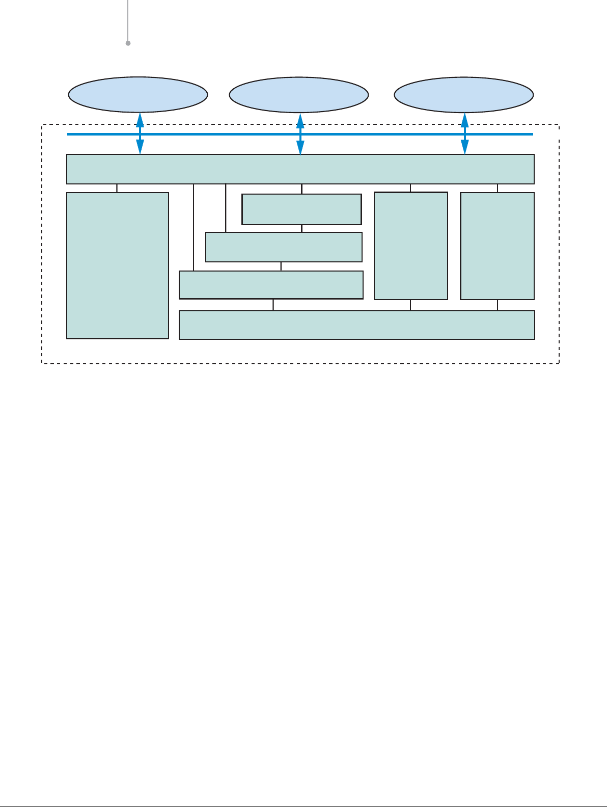
The Intel NetStructure SIU520 SS7 signaling gateway is
an SS7 network access product that provides a resilient
interface to SS7 networks via a TCP/IP local area network (LAN). As shown in Figure 1, SIU520 software
includes SS7 protocol layers, as well as a configuration
and management module. The SIU520 supports multiple
SS7 signaling links within the same pulse code modulation (PCM) trunk interface or over multiple PCM trunks.
The SIU examines the timeslots carrying the SS7 information and processes them accordingly, outputting this data
to the LAN using TCP/IP. Similarly, it takes commands
from the TCP/IP LAN and converts those to SS7 signals
for transmission to the SS7 network. In the receive direction, information is conveyed to the user application in
structured messages placed in a sequential queue.
For both circuit- and transaction-related operations, the
SIU520 provides the ability to automatically distribute
signaling information between a number of physically
independent application platforms, thus providing a
degree of fault tolerance within the application space.
The SS7 signaling may be presented from the network
multiplexed in a timeslot on an E-1 (2.048 MB/s) or T-1
(1.544 MB/s, also known as DS1) bearer or by a V.35
(56/64 kb/s) synchronous serial interface.
For telephony operation (using a telephony layer 4 protocol
such as ISUP or TUP), if the SS7 signaling is multiplexed
onto a PCM bearer, the voice circuits may be passed
transparently through the SIU to the application platform
that terminates the physical circuits (see Figure 2).
Circuit-switched API Operation
The message-based application programming interface
(API) operates transparently over TCP/IP Ethernet, using
software modules provided by Intel. For circuit-switched
(telephony) applications, each application platform terminates and hence controls a fixed range of physical circuits, or circuit identification codes (CICs). CICs are configured in groups of up to 32, each group normally
equating to all the circuits in a single E-1 or T-1 trunk.
Each group is terminated on a fixed application platform
or host processor, enabling the SIU to automatically
direct API messages to the correct platform.
Application Note Building Fault-tolerant SS7 Systems Using the Intel®NetStructure™ SIU520 SS7 Signaling Gateway
2
Figure 1. Structure of the Intel®NetStructure™ SIU520 SS7 Signaling Gateway
Application
#0
Configuration
and
Management
Application
#1
API Layer/Ethernet Driver
MAP or INAP or IS41
TCAP
SCCP
MTP Levels 1-3
Application
#N
Ethernet
ISUP TUP
SIU 520
Page 6
Transaction-based API Operation
TCAP-based applications can be distributed on multiple
application hosts using two different methods which are
explained in details further in this document (see “Failure
of Applications”, pg. 15). These methods imply running
TC-user application parts (such as GSM-MAP, INAP, or
IS-41) on each application host. When running any
application part above TCAP on the SIU520 itself, the
product allows operation of a single host application.
Management Interface
The SIU520 constantly monitors the state of its physical
connections, PCM trunk inputs, the communication
channel via TCP/IP Ethernet to the host processors and
reports status information to an application process
running on a user-defined host. The host elected to
receive management messages can be selected by
sending an API_MSG_COMMAND management request.
(See the Intel NetStructure SIU520 Developer’s Manual
for more information.) Host 0 is used by default.
Potential Points of Failure
In this section, the most critical points of failure of an Intel
NetStructure SIU520 SS7 signaling gateway-based system are reviewed. The list of potential points of failure
include:
■
SS7 links
■
SS7 routes
■
Power supply
■
Signaling interface unit
■
IP subnetwork
■
Application host
For each of these points of failure, a solution is provided
and implementation details are given.
Building Fault-tolerant SS7 Systems Using the Intel®NetStructure™ SIU520 SS7 Signaling Gateway Application Note
3
Figure 2. Integrating the SIU520
E-1 or T-1 Trunks,
Voice Circuits
CT Application Platform
Only
}
SIU520
E-1 or T-1 Trunks
SS7
Information
CT Application Platform
with SS7 Channel
and Voice Circuits
}
Ethernet
Page 7
Failure of SS7 Links
Problem — With a single link to the adjacent signaling
point, service is disrupted if the link goes down for some
reason (i.e., layer 1 alarm, congestion).
Solution — Link resiliency is achieved by using multiple
links between a local point code and an adjacent point
code. By definition, such links are said to belong to the
same link set, which can contain up to 16 links. Ideally,
the links of a link set should not be carried over a unique
physical medium (such as an E-1 or T-1 trunk) but,
instead, should be split over independent physical trunks.
Link failure management is a standard MTP3 operation
and is not an SIU520-specific feature. In other words,
failure between links in a same link set will happen in a
completely transparent way for the user application.
Details — In an SIU520 system configuration, two
commands are used in config.txt to configure link sets
and links: MTP_LINKSET and MTP_LINK. In this
example, two SS7 links are defined between local point
code 0x100 and adjacent point code 0x200 on time
slot 16 of PCM ports 1 and 2. (Also see Figure 3.)
Application Note Building Fault-tolerant SS7 Systems Using the Intel®NetStructure™ SIU520 SS7 Signaling Gateway
4
Figure 3. SIU Connected to Adjacent Node with Two Links in Link Set
A
* MTP_LINKSET <linkset_id> <adjacent_spc> <num_links> <flags> <local_spc> <ssf>
MTP_LINKSET 0 0x200 2 0x0000 0x100 0x08
* MTP_LINK <link_id> <linkset_id> <link_ref> <slc> <bpos> <blink> <bpos2>
*<stream> <timeslot> <flags>
MTP_LINK 0 0 0 0 0 0 0 0 16 0x0006
MTP_LINK 1 0 1 1 0 1 0 1 16 0x0006
) Load sharing between link 0 and link 1 under normal conditions
SIU520
Point Code
0x100
Link Set id 0
B) Traffic sent over link 1 under failure of link 0
SIU520
Point Code
0x100
Link id 0, slc 0
Link id 1, slc 1
SSP/SCP
Point Code
0x200
SSP/SCP
Point Code
0x200
Page 8
Failure of Routes
Problem — With a single route to a destination point
code (DPC), service can be disrupted if all the links of the
link set used to reach that signaling node fail. Route
failover is a standard MTP3 operation which does not
require any specific action from the user application.
Solution — To eliminate this single point of failure, an
alternative link set can be provided in the SIU520 system
configuration to reach the same DPC. Route failover is a
standard MTP3 operation which does not require any
specific action from the user application.
Note: When an alternative route to a given DPC is
defined in an SIU520 configuration file, a choice must be
made between two different traffic modes: load sharing
or failover. In load-sharing mode, traffic sent towards the
remote signaling point is shared between the two link
sets. In failover mode, all traffic sent towards the remote
signaling point will normally be sent using the primary link
set, unless this link set fails, in which case the traffic will
use the alternative link set. See the Intel NetStructure
SIU520 Developer’s Manual for more information on the
selection of traffic mode in the MTP_ROUTE command.
Details — This example (see Figure 4) shows two link
sets (each containing one link) being used in load-sharing
mode to reach destination point code 0x400.
Building Fault-tolerant SS7 Systems Using the Intel®NetStructure™ SIU520 SS7 Signaling Gateway Application Note
5
Figure 4. SIU520 Connected to Mated STP Pair Providing Route Resiliency
* MTP_LINKSET <linkset_id> <adjacent_spc> <num_links> <flags> <local_spc> <ssf>
MTP_LINKSET 0 0x200 2 0x0000 0x100 0x08
MTP_LINKSET 1 0x300 2 0x0000 0x100 0x08
* MTP_LINK <link_id> <linkset_id> <link_ref> <slc> <bpos> <blink> <bpos2>
*<stream> <timeslot> <flags>
MTP_LINK 0 0 0 0 0 0 0 0 16 0x0006
MTP_LINK 1 0 1 1 0 1 0 1 16 0x0006
MTP_LINK 2 1 0 0 0 2 0 2 16 0x0006
MTP_LINK 3 1 1 1 0 3 0 3 16 0x0006
* MTP_ROUTE <dpc> <linkset_id> <user_part_mask> <flags> <second_ls> <pc_mask>
MTP_ROUTE 0x400 0 0x0020 0x0003 1 0x00000000
A) Load sharing between link set 0 and link set 1 under normal
Link Set id 0
STPA
Link id 0, slc 0
SIU520
L
Point Code
0x100
Link Set id 1
B) Traffic sent over link set 1 under failure of STP
Link Set id 0
SIU520
Point Code
0x100
Link Set id 1
ink id 1, s
Link id 0, slc 0
L
ink id 1, slc 0
Point Code
0x200
lc 0
STPB
Point Code
0x300
STPB
Point Code
0x300
SSP/SCP
Point Code
0x400
SSP/SCP
Point Code
0x400
Page 9
Failure of Power Supply
Problem — Ensuring that the unit survives the loss of
one power supply and making it possible to replace a
failed power supply without affecting the availability of the
system.
Solution — The Intel NetStructure SIU520 SS7 signaling
gateway can be optionally configured with a redundant
and hot swappable power supply.
Details — Please refer to Intel NetStructure SIU520/Intel
NetStructure SG430 Hardware User Manual, Issue 3 to
obtain part numbers for redundant power supplies for the
SIU520.
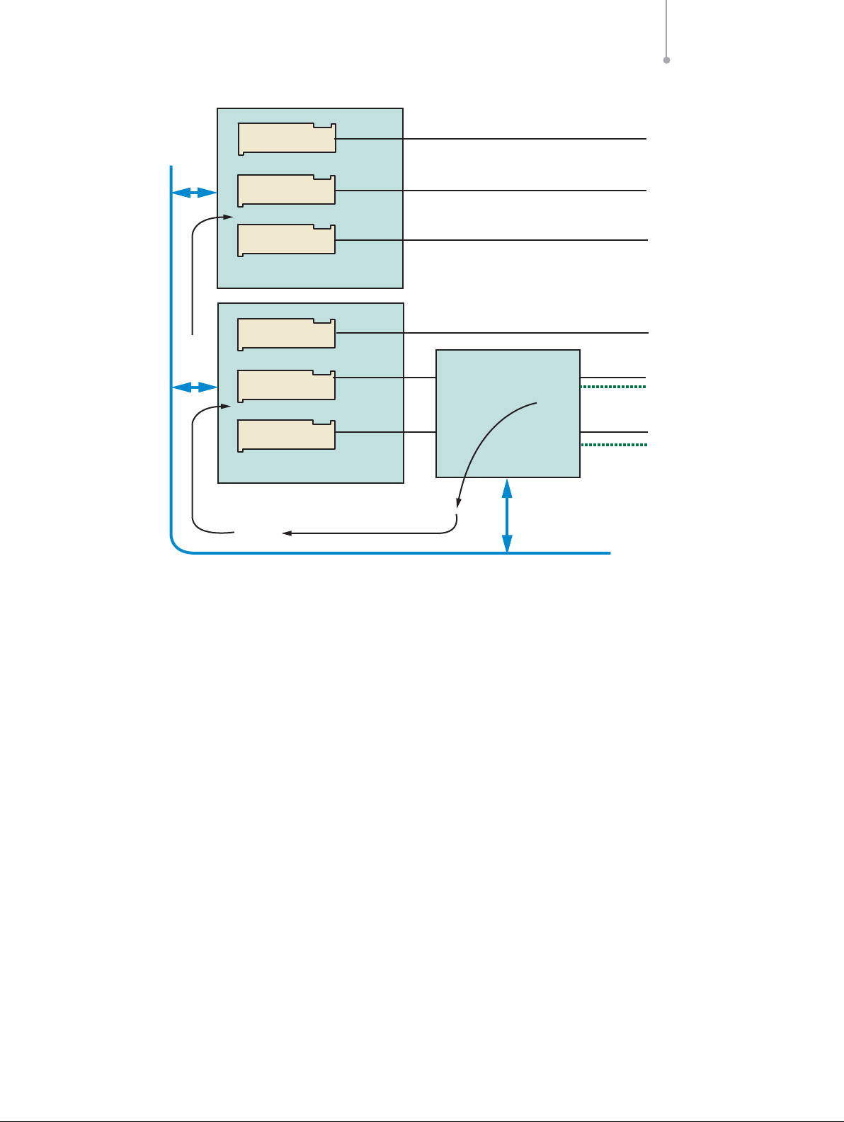
Failure of Signaling Interface Unit
Problem — Since the SIU520 provides an SS7 interface
to a distributed application, it is usually deployed for
high-density service platforms. Should the SIU of a single
SIU-based system fail, many resources (telephony circuits to TCAP dialogues) would become unavailable and
would cause major service disruption.
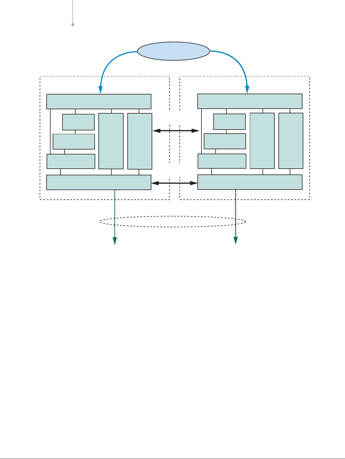
Solution — A major feature of the SIU architecture is
that two units can be configured to operate as a single
entity, sharing the same local SS7 point code. In normal
operation, signaling can be shared between two units. In
the event of a failure, signaling is maintained by the
remaining unit.
Details — In a dual configuration, one unit is assigned
as SIUA, the other as SIUB. Under normal operation, the
application uses both the resources of SIUA and SIUB
(see Figure 5).
The distributed layer 4 management is achieved using a
LAN connection and allows SS7 messages for any transaction or call to be received by either unit, regardless of
the unit that is actually processing the call or transaction.
The distributed MTP3 functionality is achieved using a
specially configured inter-SIU link set, containing one or
more signaling links. Transmit messages from each SIU
are load shared between links that connect to the local
SIU, if these are available. If all local network-facing SS7
links have failed, transmit messages are relayed to the
Application Note Building Fault-tolerant SS7 Systems Using the Intel®NetStructure™ SIU520 SS7 Signaling Gateway
6
Figure 5. Dual SIU Architecture
Application
Ethernet
SIUA SIUB
API Layer/Ethernet Driver
MAP or INAP
or IS41
TCAP
SCCP
MTP Levels 1-3
ISUP TUP
SS7
Distributed Layer 4
Management
Distributed MTP3
Management
Link Set
Ethernet
API Layer/Ethernet Driver
MAP or INAP
or IS41
TCAP
SCCP
MTP Levels 1-3
SS7
ISUP TUP
Page 10

partner SIU across the inter-SIU link set and sent out to
the adjacent signaling point by the partner unit. The interSIU link set also provides the capability of message
retrieval and retransmission when a changeover operation
occurs between the two units.
■
For circuit-switched applications, the circuit groups are
configured on both units, letting the application select
which SIU controls each group. In normal operation,
the control of circuit groups is distributed between both
the SIUA and SIUB. In the event of failure of a unit
(or for maintenance), the application can move control
of each circuit group from one SIU to the other.
■
For transaction-based applications, the transactions are
shared equally between the two units.
Routing Architectures of a Dual-resilient SIU
System
The routing options (i.e., straight connection to the DPC
vs. indirect connection via a pair of STPs) described in
this section will vary based on the actual network architecture that is being supported for a particular application.
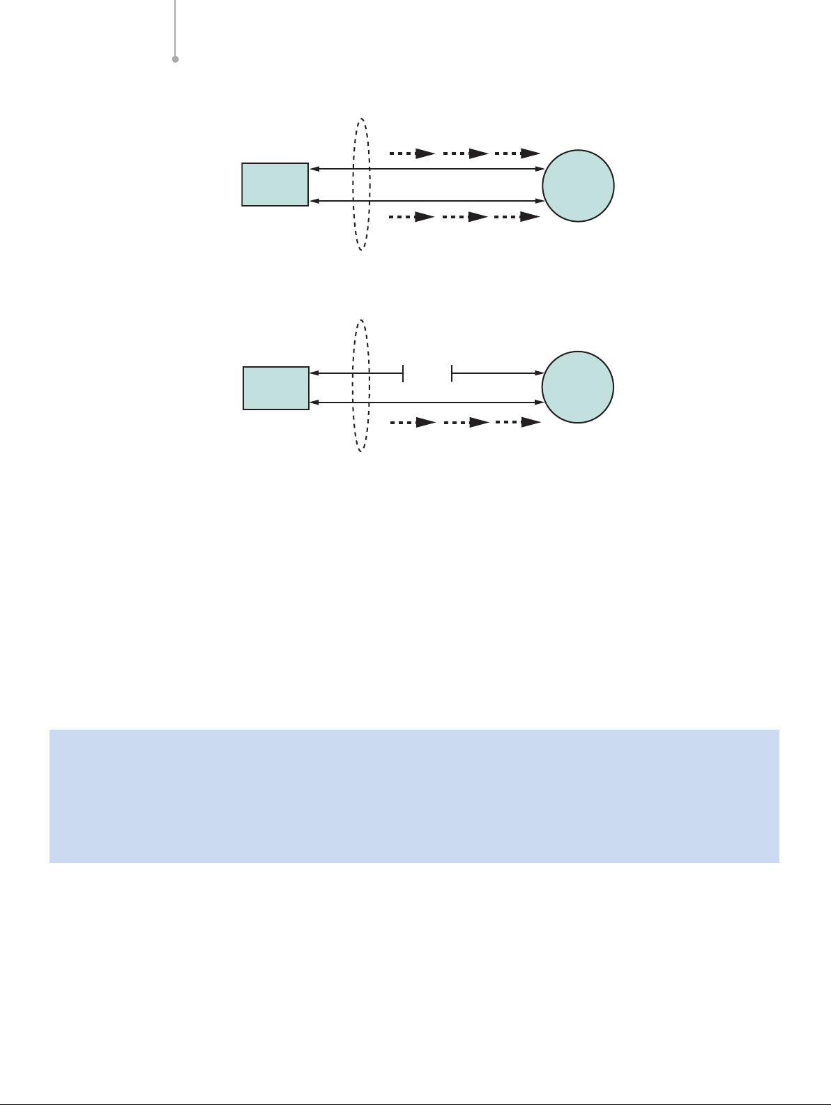
Connection to a Single Adjacent Signaling Point
Figure 6 shows two possible routing alternatives for SIUA
routing to an adjacent SSP or SCP. Messages issued
from SIUA are sent to the destination SSP or SCP using
local SS7 links if available. If these fail, transmit messages
are relayed through SIUB over the inter-SIU links. In this
case, the DPC is also the adjacent signaling point.
Although Figure 6 shows an SIU pair connected to a single adjacent signaling point, the pair may be connected
to multiple destinations.
The number of links allocated in the inter-SIU link set has
to be carefully calculated. Since these links will be used
for outgoing traffic only, they can be used at a higher
capacity than network-facing links. Moreover, since only
half of the traffic can potentially be routed through that
link set, a common rule is to allocate a fourth of the total
number of network-facing links in the inter-SIU link set. In
a fully populated pair of SIU520 (12 links per unit; 24 links
total), 16 links will be typically allocated in the networkfacing link set and four links will be allocated in the interSIU link set.
Routes to destinations are configured such that there is a
primary link set (the link set from the SIU to the DPC) and
a secondary link set (the inter-SIU link set) which is used
only when the primary link set has failed.
Building Fault-tolerant SS7 Systems Using the Intel®NetStructure™ SIU520 SS7 Signaling Gateway Application Note
7
Figure 6. Transmit Routing to a Single Destination
A) Normal routing case
Single Point Code
Inter-SIU
Link Set
SIUA
Link Set id 0
B) Routing under network link failure
Inter-SIU
Link Set
F-Links
SIUB
Link Set id 1
Single Point Code
SIUA
SSP/SCP
Link Set id 0
SIUB
SSP/SCP
Link Set id 1
Page 11

In case (A), since the F-links all exist in the same link set,
messages may be sent from the adjacent SSP/SCP to
either SIUA or SIUB. If an SIU receives a message from
the SS7 network for a circuit or transaction that it does
not control, this receive message is passed automatically
to the other SIU for processing via the TCP/IP LAN.
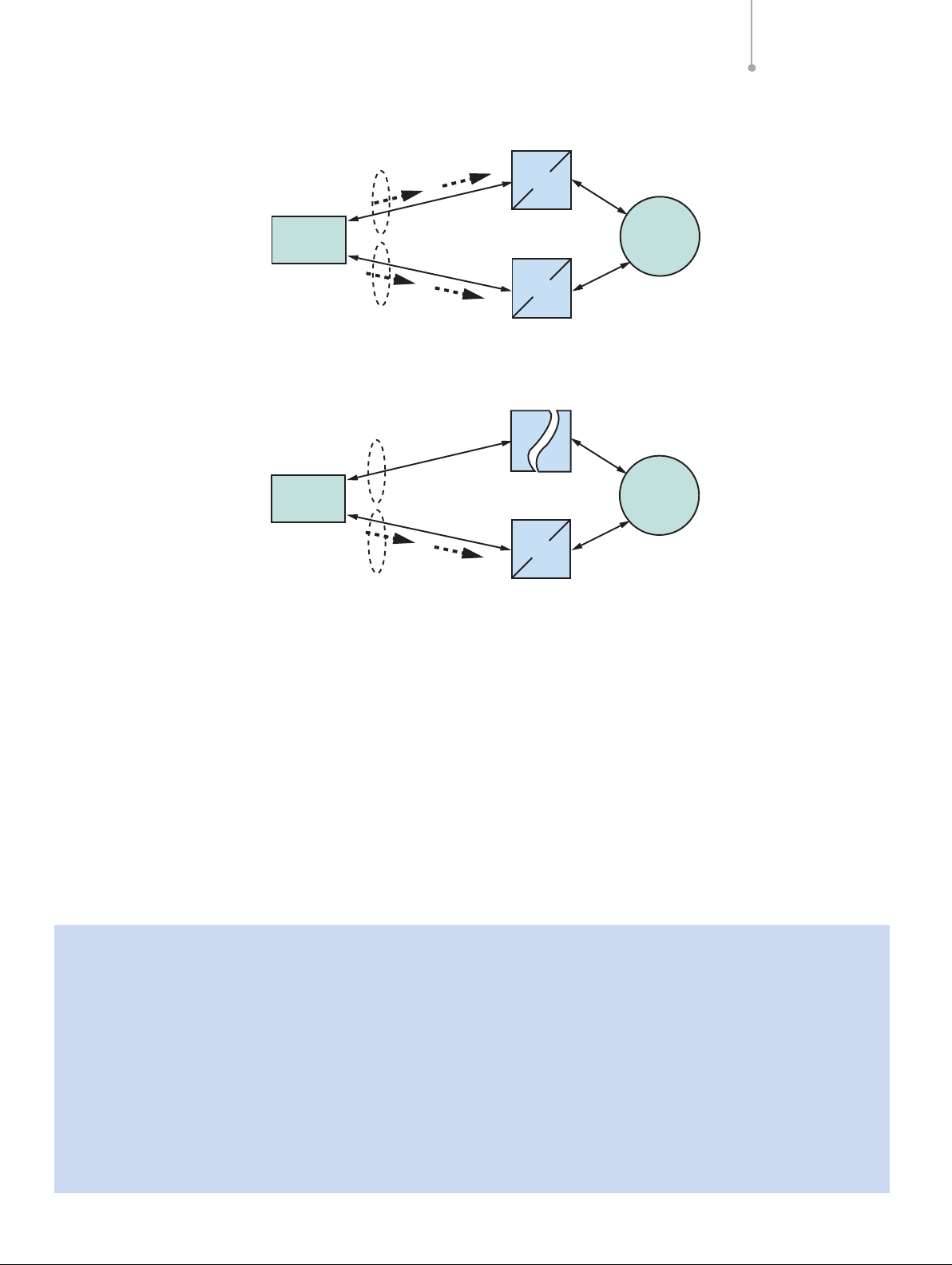
Connection to an Adjacent Mated STP Pair
There are two ways of connecting a pair of SIUs to a
mated STP pair. In the first method, the straight link
configuration, each SIU is configured with two link sets:
one link set containing STP-facing links, plus the
inter-SIU link set. The straight link configuration consists
in connecting SIUA to STPA and SIUB to STPB, as
shown in Figure 7.
The second method, the crossed link configuration,
consists of adding crossed link connections between
SIUA and STPB and between SIUB and STPA to the
previous mode. In a crossed link configuration, each SIU
is configured with three linksets: two link sets containing
the links towards each STP, plus the inter-SIU link set
(see Figure 8). The configuration of the DPC will contain
the link set IDs of the two link sets connected to the
STPs. Load sharing can be enabled to take advantage of
all the system resources. In such a configuration, the
inter-SIU link set is not used for traffic failover, but only for
synchronization of network management messages.
Consequently, a single link within this link set is fairly
enough, giving an increased bandwidth for networkfacing links.
The inter-SIU link must be carefully dimensioned as it will
have to support the outgoing traffic of the SIU that would
have lost its entire network-facing links, as shown in
Figure 9. Again, a common practice is to allocate a fourth
of the total number of network-facing links in the interSIU link set.
Application Note Building Fault-tolerant SS7 Systems Using the Intel®NetStructure™ SIU520 SS7 Signaling Gateway
8
Figure 7. Dual-resilient SIUs Connected to a Mated STP Pair in a Straight Link Configuration
Figure 8. Dual-resilient SIUs Connected to a Mated STP Pair in a Crossed Link Configuration
Link Set id 0
Link Set id 0
Single Point Code
Inter-SIU
Link Set
SIUA
SIUB
Single Point Code
Inter-SIU
Link Set
SIUA
SIUB
Link Set id 1
STPA
A-Links
STPB
Link Set id 2
Link Set id 1
STPA
STPB
SSP/SCP
SSP/SCP
Link Set id 2
Page 12

Table 1 compares the advantages and disadvantages of these methods.
Table 1. Comparison of a Straight Link Configuration vs. a Crossed Link Configuration
Comparison Subject Straight Configuration Crossed Configuration
Load sharing -+
STPA can only load share traffic Each STP can load share between the two SIUs,
for SIUA and vice-versa optimizing the resource utilization
Network-facing links +-
failure SIUA can rely on SIUB to send When an SIU loses its network-facing links, the
outgoing traffic upon failure of its application must activate circuit groups on the
entire network-facing links surviving SIU (for ISUP-based application)
Inter-SIU link set -+
dimensioning Need to allocate 1/4 of all Need to allocate a single link, maximizing the
network facing links (e.g., 16 number of network-facing links (e.g., 22 network facing
network facing links and four links and one inter-SIU link). Allocating a single link means
inter-SIU links) there are two single points of failure in the system.
For best resilience, the inter-SIU link set should contain
two links spread across two cards in each SIU.
Building Fault-tolerant SS7 Systems Using the Intel®NetStructure™ SIU520 SS7 Signaling Gateway Application Note
9
Figure 9. Transmit Routing Through Mated STPs
A) Normal routing case (both network link sets available)
Single Point Code
Inter-SIU
Link Set
Link Set id 0
B) Routing under failure of network link set between SIUA and adjacent STP
Inter-SIU
Link Set
Link Set id 0
SIUA
SIUB
Single Point Code
SIUA
SIUB
Link Set id 1
A-Links
Link Set id 2
Link Set id 1
A-Links
C-Links
C-Links
STPA
STPB
SSP/SCP
SSP/SCP
STPB
Transmit Traffic from SIUA
Transmit Traffic from SIUB
Link Set id 2
Page 13

Dual SIU Architecture for Circuit-Switched
Applications
Within the SIU environment, circuits are configured in
groups, each group equating to all the circuits
multiplexed onto a single E-1 or T-1 PCM trunk. The SIU
provides the SS7 circuit control and the application
platform (or host) terminates the physical channels,
typically with a voice processor.
For normal operation, half the circuit groups are
controlled by SIUA and half by SIUB. As each application
platform starts up and connects to both SIUA and SIUB,
the application must nominate which SIU is to control the
signaling for each of the circuit groups it terminates. A
circuit group activation command must be sent to the
selected SIU for each circuit group. Any outgoing
messages for circuits in this group must be sent to this
SIU, as shown in Figure 10.
The adjacent signaling point views the links connected to
SIUA and SIUB as the same link set and, as such, is free
to send messages for the circuits controlled by SIUA to
either unit. In the case where SIUB receives a message
for a circuit controlled by SIUA, the message is
automatically routed to the correct controlling circuit
group using the LAN Ethernet connection (shown by the
shaded arrows in Figure 10).
Application Note Building Fault-tolerant SS7 Systems Using the Intel®NetStructure™ SIU520 SS7 Signaling Gateway
10
Figure 10. Normal Routing for Circuit Group 0 When Controlled by SIUA
MTP1-3
Circuit Group 0
[Active]
Circuit Group 1
[Inactive]
SS
7
Adjacent
Signaling
Point
Application
TCP/IP Ethernet
SIUA
Inter-SIU
SS7 Link Set
SIUB
Transmit traffic for circuits active on SIUA
Received traffic for circuits active on SIUA
Circuit Group 0
[Inactive]
Circuit Group 1
[Active]
MTP1-3
SS7
Page 14

If all the links between the controlling SIU and the
adjacent signaling point fail, all transmit traffic is
automatically routed to the adjacent signaling point
through the inter-SIU link set as shown in Figure 11. The
application should continue to use the SIU as before,
directing all outgoing circuit requests to SIUA.
If the controlling SIU fails, the application is informed of
the failure and should transfer control of the circuit group
to the remaining unit.
■
Calls in a steady state (speech) will continue uninter-
rupted.
■
Outgoing calls in a set-up state during the transfer
should be re-attempted.
■
Incoming calls being set-up by the interconnected SS7
equipment will also fail and will be re-attempted
remotely.
Building Fault-tolerant SS7 Systems Using the Intel®NetStructure™ SIU520 SS7 Signaling Gateway Application Note
11
Figure 11. Routing When All Local Links Have Failed, Group 0 Controlled by SIUA
MTP1-3
Circuit Group 0
[Active]
Circuit Group 1
[Inactive]
SIUA
Application
TCP/IP Ethernet
SIUB
Transmit traffic for circuits active on SIUA
Received traffic for circuits active on SIUA
Inter-SIU
SS7 Link Set
SS7
Circuit Group 0
[Inactive]
Circuit Group 1
[Active]
MTP1-3
Adjacent
Signaling
Point
Page 15

The circuit group control will then appear as shown in
Figure 12.
The user application software should reset all idle circuits
following a transfer, and reset all remaining circuits as
they become idle.
When the failed unit recovers, control of the circuits may
be transferred back by the application.
Circuit group control is transferred by the application in
two stages. The group should be deactivated from one
unit (if communication with that unit is possible) before
being activated on the partner SIU. To protect against
control being active on both units at the same time, the
SIU automatically issues a deactivate command to the
partner unit in response to an activate command from
the host application and checks the status of each circuit
group on the partner unit. An API management event
indication is given if dual control is detected.
Application Note Building Fault-tolerant SS7 Systems Using the Intel®NetStructure™ SIU520 SS7 Signaling Gateway
12
Figure 12. Routing Following Failure of SIUA
SIUA
Application
TCP/IP Ethernet
SIUB
Adjacent
Signaling
Point
SS7
Circuit Group 0
[Active]
Circuit Group 1
[Active]
MTP1-3
Page 16

Dual SIU Architecture for Transaction-based
Applications
There are two ways of architecting a dual-resilient
SIU520-based system for processing TCAP transactions.
■
Running the SS7 stack up to SCCP on the SIUs
■
Running the SS7 stack up to TCAP on the SIUs
In the first case, TCAP and potential layers sitting on top
of TCAP run on the application host(s) and an additional
piece of software is required on each SIU to distribute
TCAP transactions to multiple application hosts. This
software option is called distributed transaction server
(DTS). Figure 13 depicts this architectural difference.
Building Fault-tolerant SS7 Systems Using the Intel®NetStructure™ SIU520 SS7 Signaling Gateway Application Note
13
Figure 13. Two Different Architectures for a TCAP Processing SIU System
A) Dual-resilient SIUs running SS7 protocol stack to TCAP
Host 0 Host N
TC User TC User
SIUA
TCAP
SCCP
MTP
. . .
Ethernet
TCAP
SCCP
MTP
SIUB
B) Dual-resilient SIUs running SS7 protocol stack up to SCCP
Host 0
TC User
. . .
TCAP
DTC
Ethernet
SIUA
DTS
SCCP
MTP
Host N
TC User
TCAP
DTC
DTS
SCCP
MTP
SIUB
Page 17

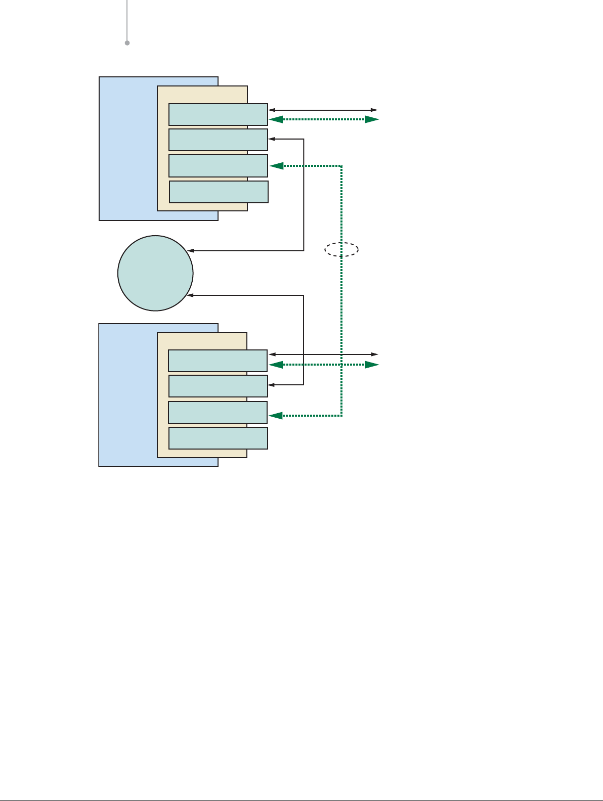
In the second case, each unit controls half of the total
available transactions. (The Intel NetStructure SIU520
SS7 signaling gateway supports up to 16,384 transactions. A dual-resilient system can consequently handle up
to 32,768 simultaneous transactions.) Each transaction is
processed for its entire duration by the SIU that
processed the first TCAP message. The user application
must therefore direct all messages for a transaction to
the same SIU, and load balance outgoing dialogues
between the two units. An incoming TCAP dialogue message other than BEGIN or QUERY is handled by the SIU
that processed the first TCAP message for that dialogue
received from the SS7 network. When an SIU receives a
TCAP message that belongs to a transaction that was
initiated on the other unit, it will pass this message to its
peer SIU over the RSI connection. This is shown in
Figure 14. Failure of an SIU reduces the number of available transactions to one-half.
In a dual-resilient transaction-based SIU system running
the SS7 stack up to SCCP on the SIU, and TCAP (and
above) on the application host, each host controls a fixed
number of transactions. Each transaction is processed
for its entire duration by the application host that
processed the first TCAP message. Upon failure of one
SIU unit, the TCAP capacity and ongoing transaction are
totally unaffected.
The architectural decision taken on where the TCAP
module is running also has consequences on the level of
application resiliency and total system capacity. These
consequences are explained in more details in “Failure of
Application”, pg. 15.
Application Note Building Fault-tolerant SS7 Systems Using the Intel®NetStructure™ SIU520 SS7 Signaling Gateway
14
Figure 14. Message Flow on a Dual-resilient System Running the SS7 Stack up to TCAP
SIUA
TCAP
instance = 0
TCAP
instance = 1
SCCP
SCCP
SS
7
MTP
MTP
SIUB
SS
SS7
7
Adjacent
Signaling
Point
Application
Ethernet
Inter-chassis
communication
(RSI)
Transmit message for transaction handled by TCAP B
Message received for transaction handled by TCAP B
Page 18

Failure of IP Subnetwork
Problem — Should one subnetwork go down due to a
network component failure, the hosts connected to the
SIU over the other subnetworks will remain active and
attempt to preserve half of the total system capacity.
Solution — There are two Ethernet ports on the SIU520.
This allows splitting the IP connections between the SIU
and the application hosts onto two physically separated
subnetworks, as shown in Figure 15. This eliminates the
risk of losing all IP connectivity in the event of a
switch/router/hub failure in the LAN.
Details — “Failure of Application”, below, shows how to
take advantage of the dynamic configuration features
offered by the SIU520 to failover the affected application
hosts to the surviving subnetwork.
Failure of Application
Problem —The failure of an application host leads to the
loss of a portion of system resources.
Solution —The most basic feature ensuring this is that
the application can be deployed on multiple hosts. In a
software release bigger than v1.06, the SIU520 supports
up to 64 hosts. For circuit-switched applications, failure
of a host generally means loss of the physical trunk
interface; hence, there is no need of transferring the logic
to other (surviving) hosts. More sophisticated features are
available to allow TCAP-based applications to failover to
other hosts.
Details — For TCAP-based applications, the SIU allows
operation of multiple application hosts interfacing directly
to TCAP, hence giving a certain level of resiliency in the
user application space. Two methods are available for
this purpose and are explained here.
TCAP Resiliency Based on Dialogue Groups
Fixed ranges of TCAP dialogues can be created in the
SIU520 configuration file and assigned to different
application hosts. (TCAP dialogue groups are defined
using the TCAP_CFG_DGRP command in config.txt.
More information about this command can be found in
the Intel NetStructure SIU520 Developer’s Manual.) The
application program running on each host must therefore
ensure that only dialogue identifiers from the assigned
range are used. Optionally, a TCAP-user layer such as
MAP, INAP, or IS41 can run on each application host to
provide some application part functionalities. Figure 16
describes such a distributed architecture where TCAP
transactions are handled by four different hosts, each of
them running MAP and a MAP application. The total
number of TCAP dialogues for the whole system is
16,384 and this number does not depend on the number
of hosts.
Building Fault-tolerant SS7 Systems Using the Intel®NetStructure™ SIU520 SS7 Signaling Gateway Application Note
15
Figure 15. Dual LAN Operation on the SIU520
Application
Host
Application
Host
Subnetwork 1
S
ubnetw
or
k 2
Subnetwork 2
Subnetwork 1
SIU520
Page 19

TCAP Resiliency Based on DTS/DTC Option
Alternatively, it is possible to distribute SCCP traffic to
multiple application hosts using the distributed transaction server/distributed transaction client (DTS/DTC) software option, as shown on Part B of Figure 13. In this
architecture, TCAP and potential application parts run on
each application host. Consequently, the total capacity of
such a system depends on the number of application
hosts, each host bringing an increment of 65,536
simultaneous dialogues. Please refer to the Intel
®
NetStructure™ SS7 Protocols DTS User Guide, Issue 2,
for more information on the DTS/DTC software option.
Application Note Building Fault-tolerant SS7 Systems Using the Intel®NetStructure™ SIU520 SS7 Signaling Gateway
16
Figure 16. TCAP Dialogue Groups Example
Host 0 Host 1
Application
Application Application Application
SIU520
Host 2 Host 3
Ethernet
TCAP
SCCP
MTP
SS7
Page 20

Configuring a Dual SIU Pair
To create a dual-resilient configuration for the Intel
NetStructure SIU520 SS7 signaling gateway,
modifications are required to both the system
configuration (done using the man machine interface
[MMI]) and the protocol configuration (in the config.txt
parameter file). This may be done remotely and trans-
ferred to the SIU using FTP. More details may be found in
the Intel NetStructure SIU520 Developer’s Manual.
Hardware Requirements
Configuring an SIU as one-half of a resilient pair requires
additional hardware ports to carry the inter-SIU link set
between SIUA and SIUB. This may be achieved using
E-1/T-1 interfaces, as shown in Figure 17, or V.11 (V.35)
interfaces, as shown in Figure 18. A cable, part number
842484, can be purchased from your Intel distributor to
interconnect two V.11 ports between signaling cards
within the SIU. For more information, refer to the Intel
NetStructure SIU520 Developer’s Manual.
Building Fault-tolerant SS7 Systems Using the Intel®NetStructure™ SIU520 SS7 Signaling Gateway Application Note
17
Figure 17. Inter-SIU Link over Crossed E-1/T-1 Cable
Signaling Card
SIUA
SIUB
PCM Trunk #0
PCM Trunk #1
PCM Trunk #2
PCM Trunk #3
Signaling Card
PCM Trunk #0
PCM Trunk #1
PCM Trunk #2
PCM Trunk #3
Inter-SIU SS7 Link Set
E-1 Trunk
SS7 Network
E-1 Trunk Containing
SS7 Signaling Only
SS7 Network
E-1 Trunk Containing
SS7 Signaling Only
Page 21
The inter-SIU signaling link set can be configured to use
any signaling processor on any signaling card and may
be carried on any of the available interfaces on the
signaling card.
If V.11 interfaces are used to carry the SS7 signaling
between the SIU and the network (this is typically the
case in North America), it is possible that there will be
free E-1/T-1 PCM ports on signaling cards. These may
be used for the inter-SIU signaling.
System Configuration
The system assignment of SIUA or SIUB is made by typing one of these commands:
CNSYS:MODE=SIUA;
or
CNSYS:MODE=SIUB;
The current assignment may be displayed by typing:
CNSYP;
Changes to the config.txt Parameter File
Each SIU is configured individually. The config.txt
parameter file held on each unit reflects the configuration
view of the local unit only; hence, assignments of link set
and link identities are only unique within a single unit.
For the dual configuration, it is necessary to modify the
protocol configuration file config.txt to assign one unit
as SIUA and the other as SIUB using the
SIU_INSTANCE command. The IP address of the other
SIU must also be declared using the SIU_REM_ADDR
command.
Configuring the Inter-SIU Link
The inter-SIU link set should be defined on both units
using the MTP_LINKSET command with bit 15 of the
<flags> parameter set to 1. This link set must have the
same value defined for the <local_spc> and
<adjacent_spc> values; this will be the local point code
of the SIU pair. Links are added to the inter-SIU link set
Application Note Building Fault-tolerant SS7 Systems Using the Intel®NetStructure™ SIU520 SS7 Signaling Gateway
18
Figure 18. Inter-SIU Link Set over V.11
Signaling Card
PCM Trunk #0
PCM Trunk #1
SIUA
V.11 Port #A
V.11 Port #B
Voice
Processing
Platform
SS7 Network
E-1 or T-1 Trunk Containing
SS7 Signaling and Voice Circuits
Inter-SIU SS7 Link Set
Signaling Card
PCM Trunk #0
PCM Trunk #1
SIUB
V.11 Port #A
V.11 Port #B
SS7 Network
E-1 or T-1 Trunk Containing
SS7 Signaling and Voice Circuits
Page 22

using the MTP_LINK command, assigning incrementing
<link_ref> and <slc> values as normal. The <bpos>
and <blink> parameters define which SS7 processor
(there are three on each signaling card) manages each
link. If a V.11 port is being used, <blink> must be either
1 or 2.
For a link using a PCM port, the physical location of the
link is specified by setting stream and timeslot: stream 16
is the PCM port closest to the green LED on the signaling
card, stream 17 the lower PCM port. To use a serial link,
the MTP_LINK <flags> bit 14 should be set to 1,
<stream> and <timeslot> both to 0. One of the units
should act as the V.11 port clock master, the other as
slave; hence, one SIU must also have <flags> bit 13
set to 1.
For example, to configure an inter SIU link, on linkset_id
0, to use V.11 port A on the first board in a SIU520, this
command would be used to define a V.11 clock slave:
MTP_LINK 0 0 0 0 1 1 1 1 0 0x4006, while
MTP_LINK 0 0 0 0 1 1 1 1 0 0x6006 would
define a V.11 port clock master.
Routing Configuration
A route should be defined on both SIUA and SIUB for the
inter-SIU link set using the MTP_ROUTE command
referencing the appropriate <linkset_id> with a <dpc>
value set to the point code of the SIU pair. This route
may only be specified to operate over a single link set.
Each DPC that may be accessed from the application
must have an accompanying MTP_ROUTE declaration.
For dual operation, each route includes a preferred link
set, the <linkset_id> parameter, and a secondary link
set specified by <second_ls>. linkset_id should reference the link set connecting the SIU to the appropriate
adjacent signaling point, second_ls must be set to the
linkset_id assigned to the inter-SIU link set.
Circuit Group Configuration
For dual operation, each SIU should contain identical
circuit group declarations using the appropriate
ISUP_CFG_CCTGRP or TUP_CFG_CTGRP commands.
These circuit group configurations do not become active
on either unit until an Activate Circuit Group API
command has been issued to a particular SIU.
Example Configuration
To define routing to the DPC 200 below (which is also the
adjacent point code), using the first E-1 port on the first
signaling card in a SIU520, the configuration (Figure 19)
would be
For SIUA
MTP_CONFIG 0 0 0x0000
MTP_LINKSET 0 100 1 0x8000 100 0x8
MTP_LINKSET 1 200 1 0x0000 100 0x8
MTP_LINK 0 0 0 0 1 1 1 1 0 0x4006
MTP_LINK 1 1 0 0 1 2 1 2 16 0x0006
MTP_ROUTE 100 0 0x0020
MTP_ROUTE 200 1 0x0020 0x0001 0
For SIUB
MTP_CONFIG 0 0 0x0000
MTP_LINKSET 0 100 1 0x8000 100 0x8
MTP_LINKSET 1 200 1 0x0000 100 0x8
MTP_LINK 0 0 0 0 1 1 1 1 0 0x6006
MTP_LINK 1 1 0 1 1 2 1 2 16 0x0006
MTP_ROUTE 100 0 0x0020
MTP_ROUTE 200 1 0x0020 0x0001 0
(up_enable was set for ISUP, user part SI = 5 for the
example above)
Building Fault-tolerant SS7 Systems Using the Intel®NetStructure™ SIU520 SS7 Signaling Gateway Application Note
19
Figure 19. Example Configuration to an Adjacent SSP/SCP
Single Point
Code
Inter-SIU
Link Set
SIUA
Link id 1, slc 0
Link Set id 0
SIUB
Link_id 0,
slc 0
Point
Code 100
SSP/SCP
Link id 1, slc 1
Link Set id 1
Point
Code 200
Page 23

For an SIU pair connected to a mated STP pair, carrying
the inter-SIU link over the second E-1 port of the first
signaling card the configuration (Figure 20) would be:
For SIUA
MTP_CONFIG 0 0 0x0000
MTP_LINKSET 0 300 1 0x8000 300 0x8
MTP_LINKSET 1 400 1 0x0000 300 0x8
MTP_LINK 0 0 0 0 1 1 1 1 0 0x4006
MTP_LINK 1 1 0 0 1 2 1 2 16 0x0006
MTP_ROUTE 300 0 0x0020
MTP_ROUTE 400 1 0x0020 0x0001 0
MTP_ROUTE 500 1 0x0020 0x0001 0
MTP_ROUTE 600 1 0x0020 0x0001 0
For SIUB
MTP_CONFIG 0 0 0x0000
MTP_LINKSET 0 300 1 0x8000 300 0x8
MTP_LINKSET 1 500 1 0x0000 300 0x8
MTP_LINK 0 0 0 0 1 1 1 1 0 0x6006
MTP_LINK 1 1 0 0 1 2 1 2 16 0x0006
MTP_ROUTE 300 0 0x0020
MTP_ROUTE 400 0 0x0020 0x0001 0
MTP_ROUTE 500 1 0x0020 0x0001 0
MTP_ROUTE 600 1 0x0020 0x0001 0
Run-time Operations of a Dual-resilient
SIU System
Connecting a Host to Two SIUs
In a dual SIU system, each host should connect to both
SIUA and SIUB at start-up. This is achieved using the
rsicmd utility twice: first with an siu_id of 0 for SIUA and
second with an siu_id of 1 for SIUB. For example, if
SIUA has an IP address of 123.234.345.110 and SIUB
an IP address of 123.234.345.220, the entry in the host’s
system configuration file, system.txt, would be:
FORK_PROCESS rsicmd 0 0xef 0
123.234.345.110 9000
FORK_PROCESS rsicmd 1 0xef 0
123.234.345.220 9000
The “concerned module id” (0xef in this case) will
receive status indications from the rsi process for both
connections. The id field of the MSG header is set to the
siu_id to identify the link that each status indication
relates to.
The ability to communicate between a host and an SIU is
indicated by RSI_MSG_STATUS messages received by
the conc_id application process (0xef in this case).
Application Note Building Fault-tolerant SS7 Systems Using the Intel®NetStructure™ SIU520 SS7 Signaling Gateway
20
Figure 20. Example Configuration to an Adjacent STP Pair
Single Point
Code
Inter-SIU
Link Set
SIUA
Link Set id 0
SIUB
Point
Code 300
Point
Link Set id 1
link_id 1, slc 0
link_id 1, slc 0
Link Set id 1
Code 400
STPA
SSP/SCP
Point
Code 600
STPB
Point
Code 500
Page 24

Communicating with Both SIUA and SIUB
The user application exchanges information with the SIU
via API messages (MSG). In a dual SIU environment,
each time the user application sends a message to the
SIU, this should be directed to either SIUA or SIUB using
a library function GCT_set_instance. In the receive
direction, the application can determine the SIU that sent
a MSG using the library function GCT_get_instance.
Function definitions may be found in the header
file sysgct.h.
GCT_set_instance
int GCT_set_instance(unsigned int
instance, HDR *h);
This function sets the destination instance number (SIU
identity or siu_id) prior to sending a message and returns
0 on success, non-zero otherwise (currently no failure
conditions are defined). SIUA is instance 0 and SIUB is
instance 1, assigned by the siu_id parameter provided to
the rsicmd utility. This function should be called
immediately before GCT_send.
GCT_get_instance
unsigned int GCT_get_instance(HDR *h);
This function returns the instance number (SIU identity or
siu_id) after receiving a message. The parameter h is a
pointer to the HDR structure at the start of the received
MSG. The returned value will be either 0 or 1. SIUA is
instance 0 and SIUB is instance 1, as assigned by the
siu_id parameter provided to the rsicmd utility.
Transferring Control of a Circuit Group between
SIUs
Activating and Deactivating Circuit Groups
Configuration commands for all circuit groups must be
present on both SIUs. At run time, the application running
on each host should select which SIU is currently in control of each group by “activating” and “deactivating”
groups on a particular SIU.
Circuit groups are activated and deactivated using the
API_MSG_COMMAND message (type 0x7f0f), with a
cmd_type of 8 to activate a group and a cmd_type of 9
to deactivate a group. The format of this message is
detailed in the Intel NetStructure SIU520 Developer’s
Manual. This message should be issued with a request
for a response (an acknowledgement); this will be
returned to the requesting application with a status value
of zero (indicating “success”) or non-zero values (indicating “busy” or “failure”).
System Initialization
When the system starts-up, the host establishes
communication with both SIUA and SIUB, either by using
the rsicmd utility or by issuing RSI configuration API
messages directly from within the application.
When the communication between the host and the SIU
is established, the RSI task on the host issues an
RSI_MSG_LINK_STATUS API message with a status
value set to 1 (link to SIU recovered) to a destination task
conc_id on the host (conc_id is set when the RSI link
was started). This message will only be received by the
application if the RSI link is configured with the conc_id
set to the application’s module ID.
The ID field of this message is set to 0 to indicate SIUA
and 1 to indicate SIUB. When the link to the SIU that
normally controls a circuit group (the primary SIU)
becomes active, the application should issue an activate
group command to that SIU, specifying that circuit group
(using its group ID). The SIU processes API commands
sequentially and the application must wait for an
acknowledgement of this command before proceeding.
An acknowledgement that indicates “busy” should cause
the application to re-attempt the activate command.
The application should wait for a period of time sufficient
to establish communication to the preferred SIU before
deciding that the preferred unit is not available and
activating circuit groups on the non-preferred or
secondary SIU.
Once the acknowledgement of the activation of a circuit
group is received, the circuits should be reset to force the
circuits into a known, idle state. This is achieved using
the Circuit Group Status Control (CGSC) Request
API message, detailed in the appropriate Programmer’s
Manual. The circuit reset is acknowledged by the
terminating exchange; this acknowledgement is passed
to the user application as a circuit group status
confirmation API message. On receipt of this, the
application may commence using the associated circuits
for calls.
Failure Detection
The event that triggers the application to transfer circuit
groups from one SIU to another is loss of communication
between the application and the SIU.
When the failure occurs, the RSI task on the affected
host detects the loss of communication and issues an
RSI_MSG_LINK_STATUS API message with a status
value set to 2 (link to SIU lost) to a destination task
Building Fault-tolerant SS7 Systems Using the Intel®NetStructure™ SIU520 SS7 Signaling Gateway Application Note
21
Page 25

conc_id on the host (conc_id is set when the RSI link
was started, optionally by rsicmd). This message will
only be received by the application if the RSI link is configured with the conc_id set to the application’s module
ID.
At the same time, the affected SIU (if it can), will issue an
API_MSG_SIU_STATUS message with status value 30
(decimal) indicating a host link failure on the specified
host ID. This message is sent to the host configured to
receive management messages (host 0 by default).
There are two failure modes that can cause loss of
communication:
■
Complete failure of one SIU in a dual-resilient pair
■
Partial TCP/IP failure causing loss of communication
between the host and one SIU of the pair via the TCP/IP
LAN
From the application’s point of view, there is no difference
in these cases since the RSI link fails in either case. From
a system point of view, the main difference is that in the
second case, the inter-SIU communication may still be
functioning.
If the affected SIU loses communication with all of its
hosts, it automatically deactivates all SS7 signaling links,
preventing any messages from being processed by any
remaining active circuit groups.
Transferring the Circuit Group
If any of the circuit groups terminating on the host are
currently active on the affected SIU, the host application
must transfer control of each affected circuit group from
the failed SIU (the primary SIU) to the remaining SIU (the
secondary SIU). Transferring a circuit group normally
involves deactivating the group on the controlling SIU
then reactivating it on the other. However, since the host
is unable to communicate with the failed SIU, the
application is only required to send an
API_MSG_COMMAND message to the secondary SIU
with cmd_type of 8 (activate circuit group) for each
affected group.
The activate circuit group command should be issued
with a request for a response and the application should
not send any call processing or circuit management
commands until the response (acknowledgement) has
been received from the secondary SIU.
The SIU processes single commands in sequence;
therefore, if an activate command is received while a
previous command is executing, the response will be
received with a non-zero status (in this case, a value
of 4 indicating “equipment busy”). The application should
reattempt the activate command on receipt of a
response indicating “busy”.
Since the failure may affect SIUA and SIUB, the host may
choose to wait for a period of time following notification
of the failure to determine if communication with the
other unit remains stable. The circuit groups may then be
transferred after this timeout if the communication to the
secondary unit remains active.
Re-synchronization of Circuit State Information
Once the circuit group activation(s) are acknowledged
from the secondary SIU, the application needs to
resynchronize the circuit state information based on the
application’s knowledge of the current circuit state. This
is achieved by sending three CGSC requests to the
secondary SIU.
Circuits that were in a call set-up state or idle (i.e., any
circuit that was not in the steady state “speech” or
“answered” state) should be RESET. Circuits that were in
the speech stage of an incoming call should be forced to
INCOMING ACTIVE; circuits that were in the speech
state of an outgoing call should be forced to OUTGOING
ACTIVE. The forcing of the circuit state to either
INCOMING ACTIVE or OUTOING ACTIVE is achieved
using the CGSC Request API message, with ptype set
to 14 (decimal) for INCOMING ACTIVE and 15 (decimal)
for OUTGOING ACTIVE.
Calls that were in outgoing set-up prior to the transfer
should be re-attempted following successful completion
of the transfer. The application should be able to
re-attempt a failed outgoing call attempt, as this may
occur under normal operating conditions. The originating
switch will automatically reattempt calls that were in
incoming set-up. When these commands are
acknowledged, the application may resume normal
call activity.
Note: The TUP protocol does not currently support
forcing of circuit states to INCOMING ACTIVE or
OUTGOING ACTIVE, this step should therefore be
omitted. No additional signaling should be exchanged for
TUP calls that were in the answered state following the
transfer. In this case, OUTGOING ACTIVE calls should be
released (at the appropriate time) with a circuit reset.
Application Note Building Fault-tolerant SS7 Systems Using the Intel®NetStructure™ SIU520 SS7 Signaling Gateway
22
Page 26

Recovery of the Failed Unit
The host application is informed of recovery of the
communication to the SIU with the same method used
for notification of the failure. The RSI_MSG_LINK_
STATUS message in this case contains a status value of
1 (link to SIU recovered).
The host nominated to receive management
indications (normally host 0) will also receive an
API_MSG_SIU_STATUS message with status value 31
(decimal) indicating a host link has recovered to the
specified host ID.
Transferring Control Back
Immediately following re-establishment of communication
with the primary SIU, the application should send
deactivate circuit group messages to this SIU to ensure
that groups are only active on the secondary unit (this
may be the case if the inter-SIU link had also failed). If the
primary unit has recovered from a complete failure, no
circuit groups will be active. This deactivate command
will fail if the groups were not active and the application
should ignore any acknowledgement of this command
with a status value indicating processing failure. A “busy”
response should cause the application to reattempt the
deactivate.
When communication with the primary SIU has been
re-established, the application should allow sufficient time
to ensure that the communication is stable, thus avoiding
repeatedly transferring circuits between units. After this
time has expired, the application should transfer control
of the affected circuit groups back to the original SIU.
This is achieved by deactivating the groups on the
secondary SIU and re-activating the ones on the primary
SIU. However, before the groups are deactivated, the
circuits in that group should be maintenance blocked.
(Using the Circuit Group Supervision Control API
message). This does not affect any calls in progress, but
will prevent these circuits from being selected for any
new incoming calls. The application should also ensure
that none of the affected circuits are selected for new
outgoing calls.
When all existing calls are completed (all the circuits are
therefore idle), the application should deactivate the circuit
group by sending an API_MSG_COMMAND message
with cmd_type of 9 to the secondary unit. When the
acknowledgement that this command has been successfully processed has been received, the groups should be
activated on the primary unit by sending an
API_MSG_COMMAND message with cmd_type of 8.
Once the acknowledgement of the activation has been
received by the application, all affected circuits should be
reset. This will force the circuits to a known (idle) state
and remove the blocking status. When the reset is
acknowledged from the terminating switch (by receipt of
a circuit group supervision control confirmation message)
the application may begin exchanging call traffic with
the SIU.
Circuit Group Conflict
Both SIUs in a dual-resilient configuration periodically poll
each other to determine which circuit groups are active
on each unit. If a group is active on both units at the
same time, an API_MSG_USER_EVENT message is
issued by the unit that detects the conflict, indicating the
group ID of the affected circuit group. The controlling
application host should issue a deactivate command to
the SIU that should not be controlling the circuit group
and re-synchronize the circuits in the group (on the
correct SIU) by issuing a reset.
The SIUs prevent this situation from arising by
automatically sending a deactivate circuit group
command to the other unit on receipt of the activate
command. If the nature of the failure is such that
inter-SIU communication is lost, it may be impossible for
the SIU to issue the automatic deactivate command.
Under this circumstance, when the failed SIU recovers,
circuit groups may be active from the time before the
initial failure. This situation is handled by the application
sending a deactivate command for all of the previously
active groups immediately following restoration of the
communication with the SIU.
Building Fault-tolerant SS7 Systems Using the Intel®NetStructure™ SIU520 SS7 Signaling Gateway Application Note
23
Page 27

Appendix A: Frequently Asked Questions
Q: How can I tell if an SIU fails?
A: The status of the communication between the host
and the SIU is indicated by RSI_MSG_STATUS
messages.
Q: What happens if an SS7 message for a circuit
or transaction is received by an SIU that does
not control that circuit or transaction?
A: The message is automatically passed to the partner
SIU using the TCP/IP LAN.
Q: If a single SS7 link to the network fails on one
of my SIUs, does my application need to take
any action?
A: No. If there are other links remaining on that unit, the
traffic will changeover to one of these; otherwise, the
traffic will be automatically passed to the other unit
via the inter-SIU SS7 link set.
Q: If all of the SS7 links to one of the SIUs fails do
I need to take any action?
A: No. The SIU will automatically re-route transmit traffic
via the inter-SIU SS7 link set.
Q: If an SIU fails do I need to take any action?
A: Yes. For switched-circuit applications, the circuit
groups controlled by the failed unit should be
activated on the remaining unit. Further information
may be found in the Intel NetStructure SIU520
Developer’s Manual.
Q: What happens if an inter-SIU SS7 link fails?
A: The SIU will changeover to use other SS7 links in the
inter-SIU link set.
Q: What happens if the Ethernet interfaces fail on
an SIU?
A: This will cause failure of all of the connections
between the hosts and the SIU. The SIU will react by
deactivating all connected SS7 links, preventing any
more signaling information from being received from
the SS7 network. The host applications will receive
an indication indicating failure of the SIU and should
transfer any circuit groups controlled by this SIU to
the remaining unit, the effective result being as
though the complete unit had failed.
Q: Do I need to activate circuit groups on a single
SIU configuration?
A: No.
Q: How many links should I configure in the
inter-SIU link set?
A: The inter-SIU link set should have sufficient capacity
to enable it to carry the maximum traffic exchanged
between a single SIU and the adjacent signaling
point. To eliminate single points of failure, more than
one link may be configured in the link set, each link
connecting to a different signaling card.
Appendix B: For More Information
Intel®NetStructure™ SIU520 Developer’s Manual, Issue
2, available at http://resource.intel.com/telecom/
support/ss7/siu520/u06siu02.pdf
Intel®NetStructure™ SIU520/Intel®NetStructure™
SG430 Hardware User Manual, Issue 3, available at
http://resource.intel.com/telecom/support/ss7/CD/
ProductSpecific/SG430/HardwareUserManual/
U05SIU03.pdf
Intel
®
NetStructure™ SS7 Protocols DTS User Guide,
Issue 2, available at http://resource.intel.com/
telecom/support/ss7/cd/GenericInfo/
GeneralDocumentation/U24SSS02-DTS-UG.pdf
Appendix C: Abbreviations
API Application programming interface
CIC Circuit identification code
DPC Destination point code
DTC Distributed transaction client
DTS Distributed transaction server
LAN Local area network
MMI Man machine interface
PCM Pulse code modulation
SIU Signaling interface unit
SS7 Signaling system 7
Application Note Building Fault-tolerant SS7 Systems Using the Intel®NetStructure™ SIU520 SS7 Signaling Gateway
24
Page 28

To learn more, visit our site on the World Wide Web at http://www.intel.com.
1515 Route Ten
Parsippany, NJ 07054
Phone: 1-973-993-3000
INFORMATION IN THIS DOCUMENT IS PROVIDED IN CONNECTION WITH INTEL®PRODUCTS. NO LICENSE, EXPRESS OR
IMPLIED, BY ESTOPPEL OR OTHERWISE, TO ANY INTELLECTUAL PROPERTY RIGHTS IS GRANTED BY THIS DOCUMENT, EXCEPT
AS PROVIDED IN INTEL'S TERMS AND CONDITIONS OF SALES FOR SUCH PRODUCTS. INTEL ASSUMES NO LIABILITY WHATSOEVER, AND INTEL DISCLAIMS ANY EXPRESS OR IMPLIED WARRANTY, RELATING TO SALE AND/OR USE OF INTEL PRODUCTS,
INCLUDING LIABILITY OR WARRANTIES RELATING TO FITNESS FOR A PARTICULAR PURPOSE, MERCHANTABILITY, OR INFRIGEMENT OF ANY PATENT, COPYRIGHT, OR ANY OTHER INTELLECTUAL PROPERTY RIGHT.
Performance tests and ratings are measured using specific computer systems and/or components and reflect the approximate performance of Intel products as measured by those tests. Any difference in system hardware or software design or configuration may affect
actual performance. Buyers should consult other sources of information to evaluate the performance of systems or components they
are considering purchasing. For more information on performance tests and on the performance of Intel products, reference
www.intel.com/go/telecom or call (U.S.) 1-800-628-8686 or 1-916-356-3104.
The Intel products referred to in this document are intended for standard commercial use only. Customer is solely responsible for
assessing the suitability of the product for use in particular applications.
Intel may make changes to specifications, product descriptions, and plans at any time, without notice.
*Other names and brands may be claimed as the property of others.
Intel, Intel NetStructure, and the Intel logo are trademarks or registered trademarks of Intel Corporation or its subsidiaries in the United
States and other countries.
Copyright © 2004 Intel Corporation
Printed in the USA Copyright © 2004 Intel Corporation All rights reserved.
e
Printed on recycled paper. 08/04 00-9206-001
 Loading...